


SK850
053-2790
Operator’s
Manual
CMW
®
Issue 1.0
Original Instruction

SK850 Operator’s Manual Overview - 1
Overview
Chapter Contents
Serial Number Location . . . . . . . . . . . . . . . . . . . . . . 2
Intended Use . . . . . . . . . . . . . . . . . . . . . . . . . . . . . . . 3
Equipment Modification . . . . . . . . . . . . . . . . . . . . . . 3
Unit Components . . . . . . . . . . . . . . . . . . . . . . . . . . . 4
Operator Orientation. . . . . . . . . . . . . . . . . . . . . . . . . 5
About This Manual . . . . . . . . . . . . . . . . . . . . . . . . . . 6
• Bulleted Lists. . . . . . . . . . . . . . . . . . . . . . . . . . . . . . . . . . . . . . . . . . . . . . .6
• Numbered Lists. . . . . . . . . . . . . . . . . . . . . . . . . . . . . . . . . . . . . . . . . . . . .6
CMW
®
Overview - 2 SK850 Operator’s Manual
t43om001w.eps
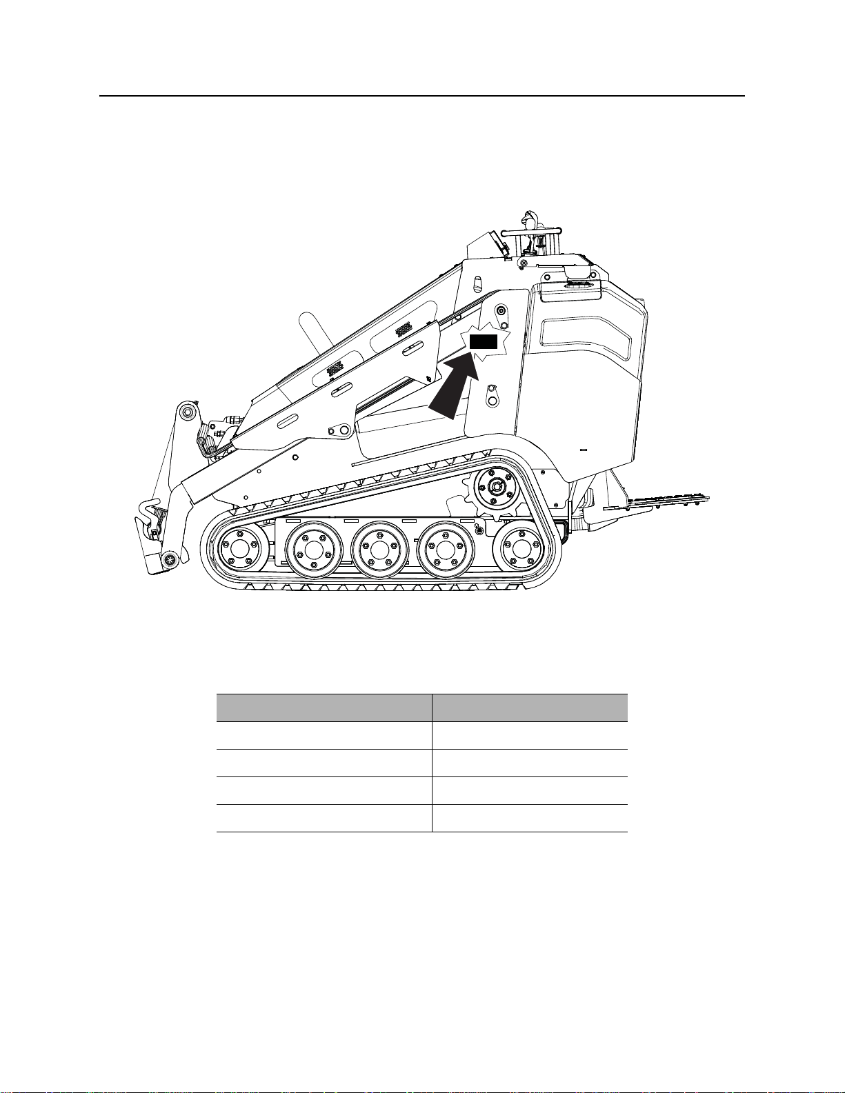
Serial Number Location
Serial Number Location
Record serial numbers and date of purchase in spaces provided. Unit serial number is located as shown.
CMW
Item
date of manufacture
date of purchase
unit serial number
engine serial number
®

SK850 Operator’s Manual Overview - 3
Intended Use
Intended Use
The SK850 is a platform, rubber track min i skid steer unit designed for light-to medium-duty constr uction
work. The SK850 has a quick attach mount plate which makes it easy for an operator to connect different
attachments. The SK850 can be used as a dedicated footings trencher using the TR50 trenching
attachment. The unit is designed for operation in temperatures typically experienced in earth moving and
construction work environments. Provisions may be required to operate in extreme temperatures. Contact
your Ditch Witch
The SK850 should be operated, serviced, and repaired only by persons familiar with its particular
characteristics and acquainted with the relevant safety procedures.
®
dealer. Use in any other way is considered contrary to the intended use.
Equipment Modification
This equipment was designed and built in accordance with applicable standards and regulations.
Modification of equipment could mean that it will no longer meet regulations and may not function properly
or in accordance with the operating instructions. Modification of equipment should only be made by
competent personnel possessing knowledge of applicable standards, regulations, equipment design
functionality/requirements and any required specialized testing.
CMW
®
Overview - 4 SK850 Operator’s Manual
t43om002w.eps
12345
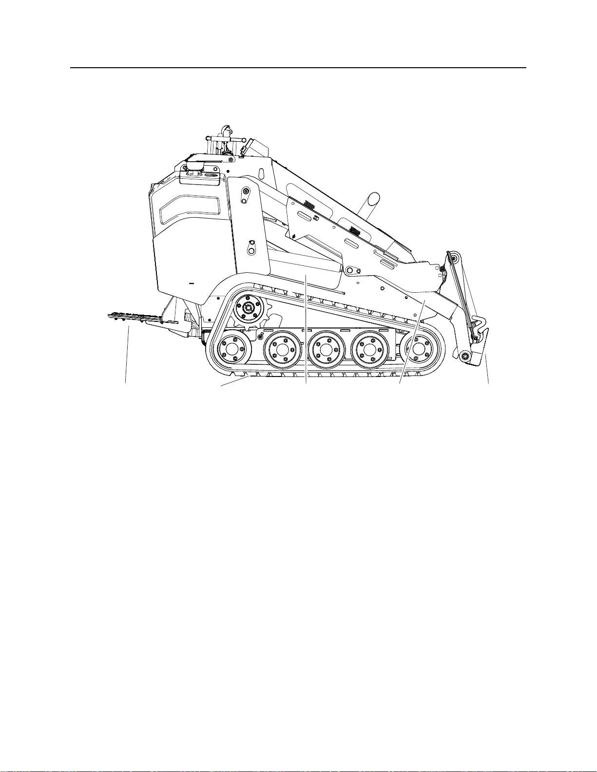
Unit Components
Unit Components
1. Operator station
2. Tracks
3. Engine compartment
4. Lift arms
5. Mount plate
®
CMW
SK850 Operator’s Manual Overview - 5
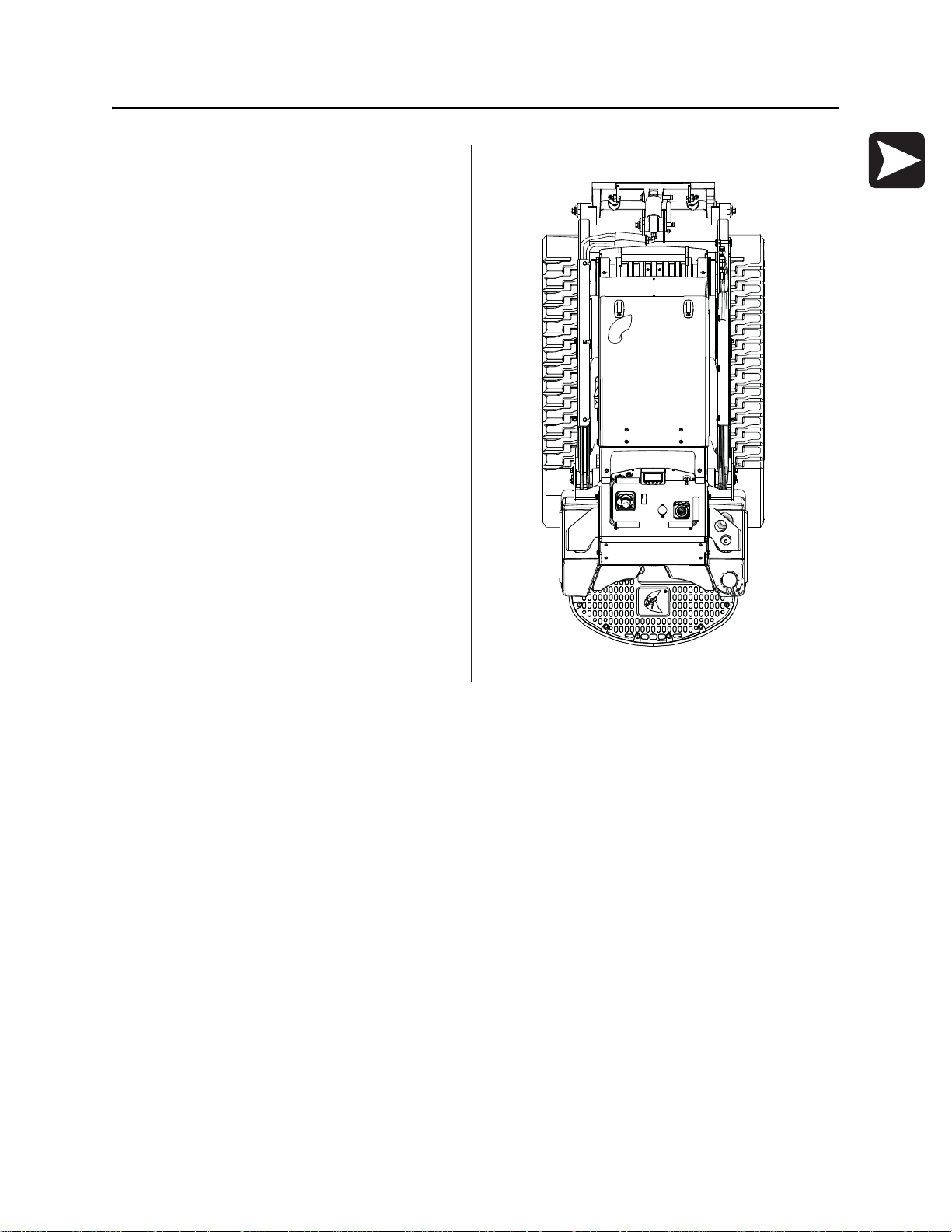
Operator Orientation
Operator Orientation
1
1. Front of unit
2. Right side of unit
3. Rear of unit
4. Left side of unit
4
t43om003w.eps
2
3
CMW
®

Overview - 6 SK850 Operator’s Manual
About This Manual
About This Manual
This manual contains information for the proper use of this machine. See the beige Operation Overview
pages for basic operating procedures. Cross references such as “See page 50” will direct you to detailed
procedures.
Bulleted Lists
Bulleted lists provide helpful or important information or contain procedures that do not have to be
performed in a specific order.
Numbered Lists
Numbered lists contain illustration callouts or list steps that must be performed in order.
CMW
®

SK850 Operator’s Manual Foreword - 7
Foreword
This manual is an important part of your equipment. It provides safety information and operation
®
instructions to help you use and maintain your Ditch Witch
Read this manual before using your equipment. Keep it with the equipmen t at all times for future reference.
If you sell your equipment, be sure to give this manual to the new owner.
If you need a replacement copy, contact your Ditch Witch dealer. If you need assistance in locating a
dealer, visit our website at www.ditchwitch.com or write to the following address:
The Charles Machine Works, Inc.
Attn: Marketing Department
PO Box 66
Perry, OK 73077-0066
USA
The descriptions and specifications in this manual are subject to change without notice. The Charles
Machine Works, Inc. reserves the right to improve equipment. Some product improvements may have
taken place after this manual was publishe d. For the latest information on Ditch Witch equipment, see your
Ditch Witch dealer.
equipment.
Thank you for buying and using Ditch Witch equipment.
CMW
®

Foreword - 8 SK850 Operator’s Manual
SK850
Operator’s Manual
Machine Works, Inc.
Issue number 1.0 / OM-10/14
Part number 053-2790
Copyright 2014
by The Charles Machine Works, Inc.
, Ditch Witch, CMW, and Roto Witch are registered trademarks of The Charles
CMW
®
SK850 Operator’s Manual Contents - 9
Content s
Overview
machine serial number, information about the type of work this machine is designed
to perform, basic machine components, and how to use this manual
Foreword
part number, revision level, and publication date of this manual, and factory contact
information
Safety
machine safety alerts and emergency procedures
Controls
machine controls, gauges, and indicators and how to use them
Prepare
procedures for inspecting and classifying the jobsite, plan ning the installation p ath (if
needed), preparing the jobsite for work, and connecting attachments
Drive
procedures for startup, cold start, driving, and shutdown
Transport
procedures for lifting, hauling, and towing
1
7
11
21
39
49
53
Trench
procedures for trenching
Complete the Job
procedures for restoring the jobsite and rinsing and storing equipment
Service
service intervals and instructions for this machine including lubrication, replacement
of wear items, and basic maintenance
Specifications
machine specifications including weights, measurements, power ratings, and fluid
capacities
Support
the warranty policy for this machine, and procedures for obtaining warranty
consideration and training
61
65
67
97
101
CMW
®

Contents - 10 SK850 Operator’s Manual
Service Record
a record of major service performed on the machine
105
CMW
®

SK850 Operator’s Manual Safety - 11
Safety
Chapter Contents
Guidelines . . . . . . . . . . . . . . . . . . . . . . . . . . . . . . . . 12
Emergency Procedures . . . . . . . . . . . . . . . . . . . . . 13
• Electric Strike Description. . . . . . . . . . . . . . . . . . . . . . . . . . . . . . . . . . . .13
• If an Electric Line is Damaged . . . . . . . . . . . . . . . . . . . . . . . . . . . . . . . .14
• If a Gas Line is Damaged . . . . . . . . . . . . . . . . . . . . . . . . . . . . . . . . . . . .15
• If a Fiber Optic Cable is Damaged . . . . . . . . . . . . . . . . . . . . . . . . . . . . .16
• If Machine Catches on Fire. . . . . . . . . . . . . . . . . . . . . . . . . . . . . . . . . . .16
Safety Alert Classifications . . . . . . . . . . . . . . . . . . 17
Machine Safety Alerts. . . . . . . . . . . . . . . . . . . . . . . 18
CMW
®

Safety - 12 SK850 Operator’s Manual
Guidelines
Guidelines
Follow these guidelines before operating any jobsite equipment:
• Complete proper training and read operator’s manual before using equipment.
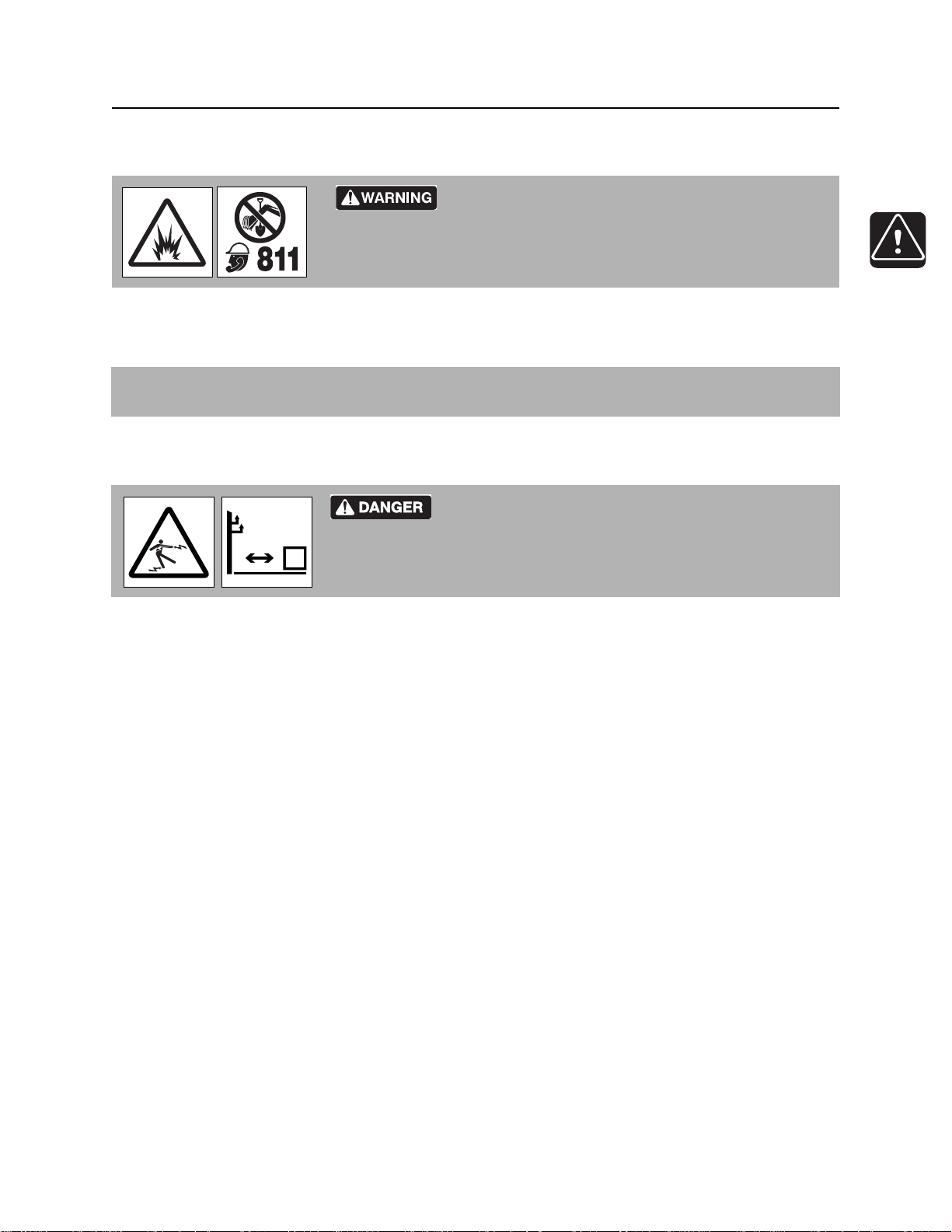
• Contact your local One-Call (811 in USA) or the One-Call referral number (888-258-0808 in USA and
Canada) to have underground utilities located before digging. Also contact any utilities that do not
participate in the One-Call service. Mark proposed p ath with white paint prior to cont acting One- Call or
utilities.
• Classify jobsite based on its hazards and use cor rect tools and machin ery, safety equipment, and work
methods for jobsite.
• Mark jobsite clearly and keep spectators away.
• Wear personal protective equipment.
• Review jobsite hazards, safety and emergency procedures, and individual responsibilities with all
personnel before work begins. Safety videos are available from your Ditch Witch
ditchwitch.com/resources/safety .
• Replace missing or damaged safety shields and safety signs.
®
dealer or at
• Use equipment carefully. Stop operation and investigate anything that does not look or feel right.
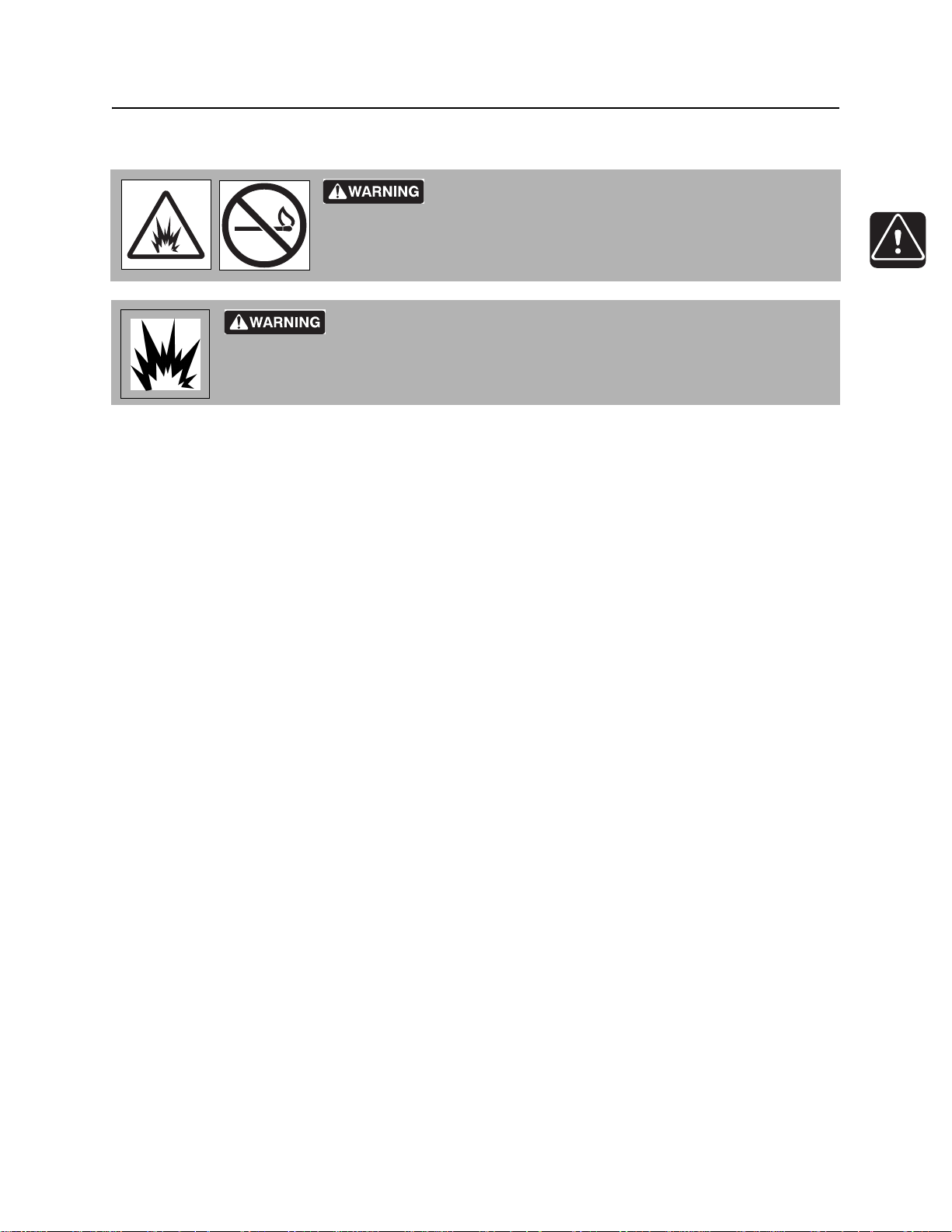
• Do not operate unit where flammable gas may be present.
• Contact your Ditch Witch dealer if you have any question about operation, ma intenance, or equipment
use.
• Complete the equipment checklist located at www.ditchwitch.com/resources/safety.
CMW
®
SK850 Operator’s Manual Safety - 13
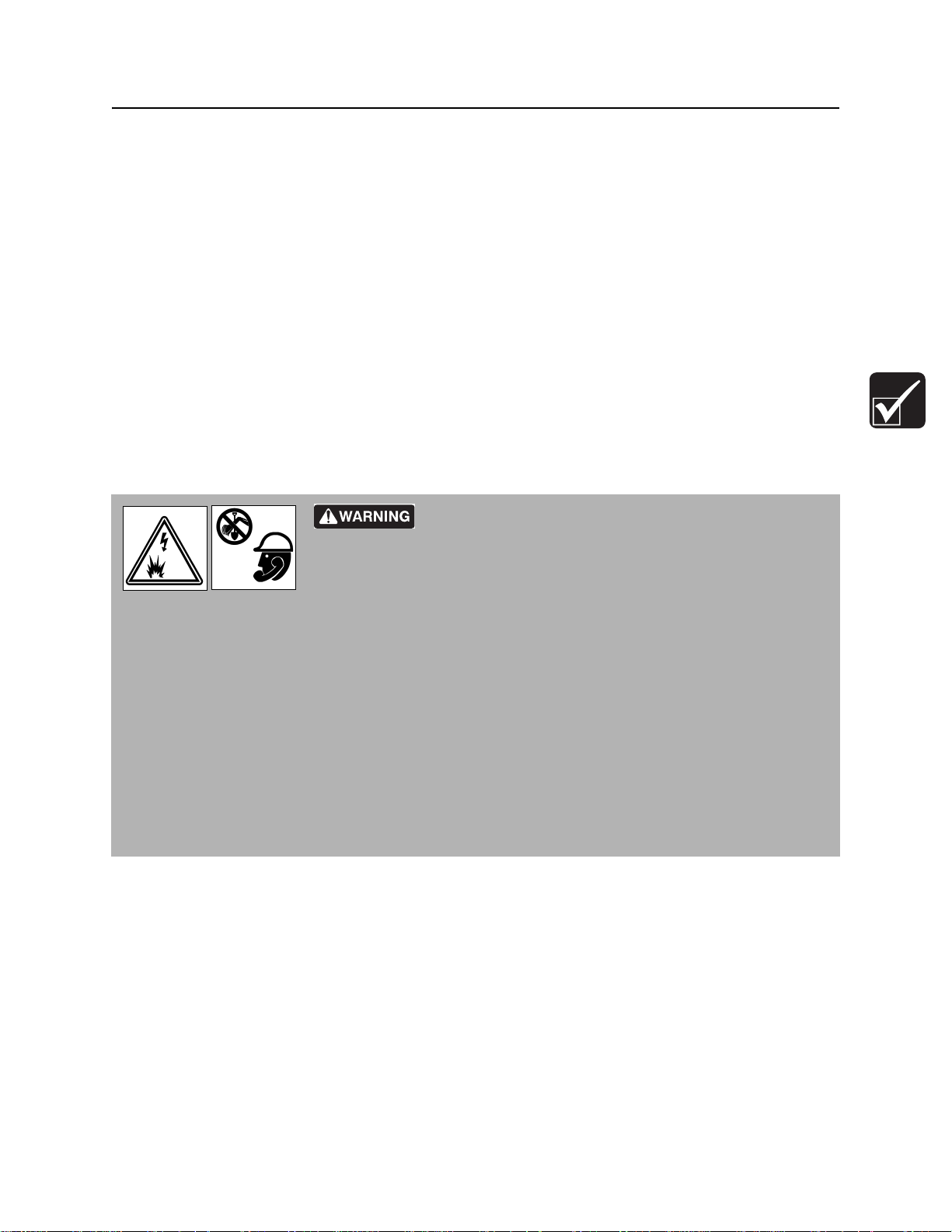
Emergency Procedures
Emergency Procedures
Jobsite hazards could cause death or serious injury. Use
correct equipment and work methods. Use and maintain proper safety
equipment.
Before operating any equipment, review emergency proc edures and check that all safety precau tions have
been taken.
EMERGENCY SHUTDOWN - Turn ignition switch to stop position or push remote e ngine stop button ( if
equipped).
Electric Strike Description
or serious injury. Know location of lines and stay away.
274-050
Electric shock. Contacting electric lines will cause death
When working near electric cables, remember the following:
• Electricity follows all paths to ground, not just path of least resistance.
• Pipes, hoses, and cables will conduct electricity back to all equipment.
• Low voltage current can injure or kill. Many work-related electrocutions result from contact with less
than 440 volts.
Most electric strikes are not noticeable, but indications of a strike include:
• power outage
•smoke
•explosion
• popping noises
• arcing electricity
If any of these occur, assume an electric strike has occurred.
CMW
®

Safety - 14 SK850 Operator’s Manual
Emergency Procedures
If an Electric Line is Damaged
If you suspect an electric line has been damaged and you are on tractor, DO NOT MOVE. Remain on
tractor and take the following actions. The order and degree of action will depend upon the situation.
• Warn people nearby that an electric strike has occurred. Instruct them to leave the area and contact
utility.
• Raise attachments and drive from immediate area.
• Contact utility company to shut off power.
• Do not return to jobsite or allow anyone into area until given permission by utility company.
If you suspect an electric line has been damaged and you are off tractor, DO NOT TOUCH TRACTOR.
Take the following actions. The order and degree of action will depend upon the situation.
• LEAVE AREA. The ground surface may be electrified, so take small steps with feet close together to
reduce the hazard of being shocked from one foot to the other. For more information, contact your
Ditch Witch dealer.
• Contact utility company to shut off power.
• Do not return to jobsite or allow anyone into area until given permission by utility company.
CMW
®
SK850 Operator’s Manual Safety - 15
Emergency Procedures
If a Gas Line is Damaged
Fire or explosion possible. Fumes could ignite and cause
burns. No smoking, no flame, no spark.
Explosion possible. Serious injury or equipment damage could occur.
Follow directions carefully.
If you suspect a gas line has been damaged, take the following actions. The order and degree of action will
depend on the situation.
• Immediately shut off engine(s), if this can be done safely and quickly.
• Remove any ignition source(s), if this can be done safely and quickly.
275-419 (2P)
• Warn others that a gas line has been cut and that they should leave the area.
• Leave jobsite as quickly as possible.
• Immediately call your local emergency phone number and utility company.
• If jobsite is along street, stop traffic from driving near jobsite.
• Do not return to jobsite until given permission by emergency personnel and utility company.
CMW
®

Safety - 16 SK850 Operator’s Manual
Emergency Procedures
If a Fiber Optic Cable is Damaged
Do not look into cut ends of fiber optic or unidentified cable. Vision damage can occur. Contact utility
company.
If Machine Catches on Fire
Perform emergency shutdown procedure and then take the following actions. The order and degree of
action will depend on the situation.
• Immediately move battery disconnect switch (if equipped and accessible) to disconnect position.
• If fire is small and fire extinguisher is available, attempt to extinguish fire.
• If fire cannot be extinguished, leave area as quickly as possible and contact emergency personnel.
CMW
®

SK850 Operator’s Manual Safety - 17
Safety Alert Classifications
Safety Alert Classifications
These classifications and the icons defined on the following pages work together to alert you to situations
which could be harmful to you, jobsite bystanders or your equipment. When you see these words and
icons in the book or on the machine, carefully read and follow all instructions. YOUR SAFETY IS AT
STAKE.
Watch for the three safety alert levels: DANGER, WARNING and CAUTION. Learn what each level
means.
indicates a hazardous situation that, if not avoided, will result in death or serious injury. This
signal word is to be limited to the most extreme situations.
indicates a hazardous situation that, if not avoided, could result in death or serious injury.
indicates a hazardous situation that, if not avoided, could result in minor or mo derate injury.
Watch for two other words: NOTICE and IMPORTANT.
NOTICE indicates information considered important, but not hazard-related (e.g., messages relating to
property damage).
IMPORTANT can help you do a better job or make your job easier in some way.
CMW
®
Safety - 18 SK850 Operator’s Manual
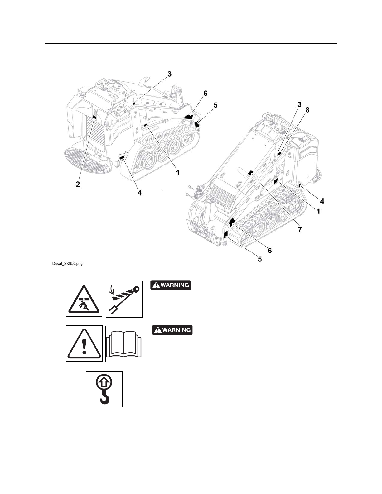
Machine Safety Alerts
Machine Safety Alerts
1
2
3
CMW
Crushing weight. Place cylinder lock on extended
cylinder and secure.
273-413
Read operator’s manual. Know how to use all
controls. Your safety is at stake.
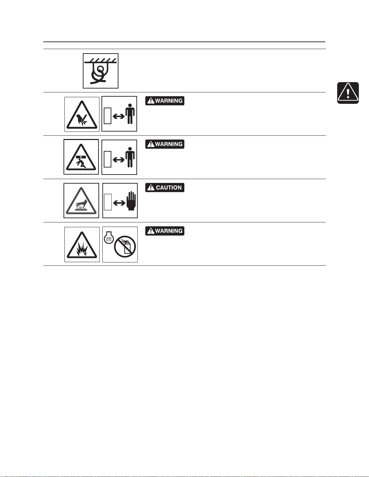
Lift point. See Tra nsport chapter for more information.
®
273-475
274-442
SK850 Operator’s Manual Safety - 19
Machine Safety Alerts
Tiedown location. See Transport chapter for more information.
274-318
4
5
275-184
Crushing weight could cause death or serious
Moving parts could cut off hand or foot. Stay away.
6
injury. Stay away.
275-326
Hot parts may cause burns. Do not touch until cool
7
or wear gloves.
275-355 (2-P)
Fire or explosion possible. Do not use starter fluid.
8
273-459 (2P), 274-206 (2P), 700-206 (2P)
CMW
®
Safety - 20 SK850 Operator’s Manual
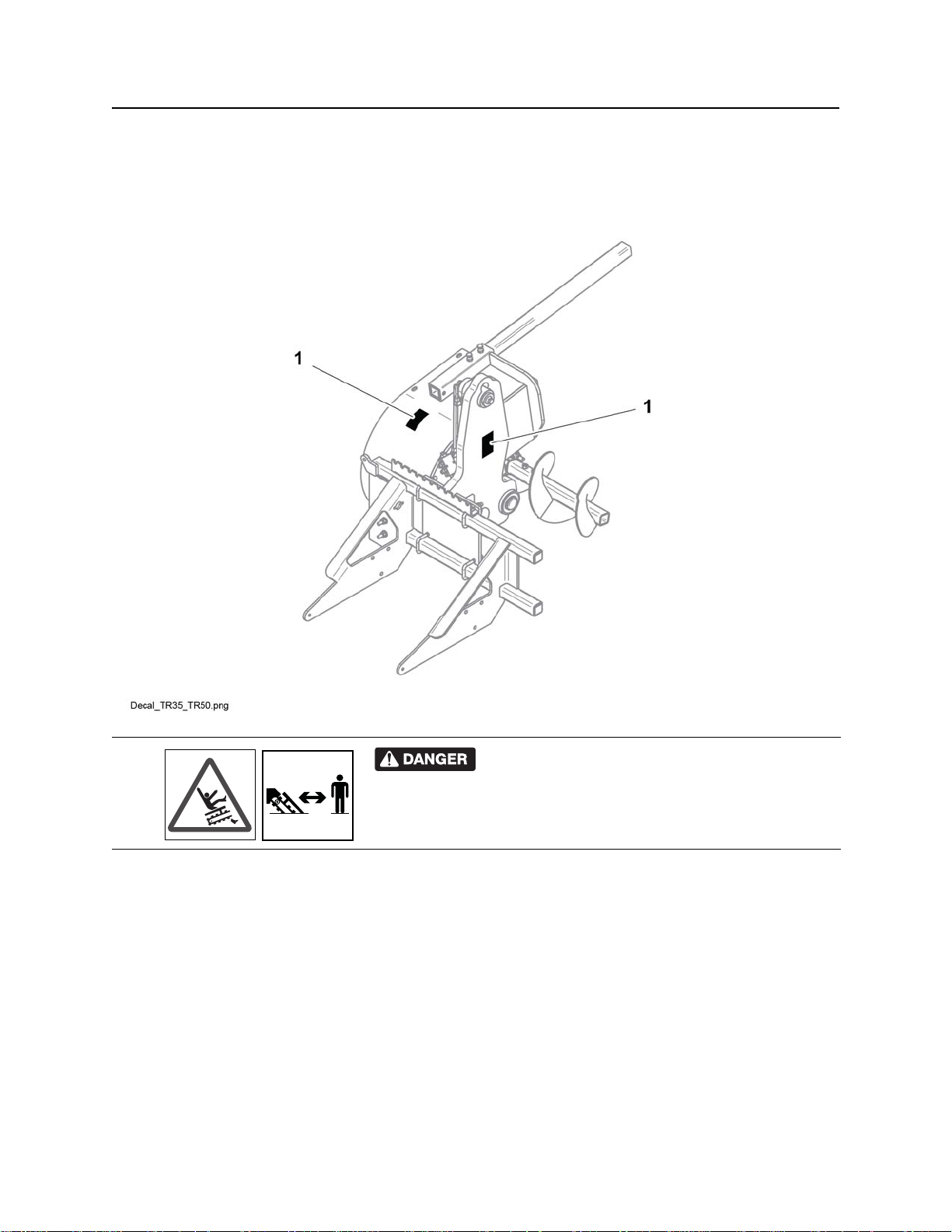
Attachment Safety Alerts
Attachment Safety Alerts
TR50
1
CMW
6ft/2m
®
cause you to fall. Stay away.
Moving digging teeth can kill. Trench cave-in can
275-097

SK850 Operator’s Manual Controls - 21
Controls
Chapter Contents
Gauges and Indicators. . . . . . . . . . . . . . . . . . . . . . 22
Graphic Display. . . . . . . . . . . . . . . . . . . . . . . . . . . . 24
Service Interval Screen . . . . . . . . . . . . . . . . . . . . . 31
Controls. . . . . . . . . . . . . . . . . . . . . . . . . . . . . . . . . . 34
Engine Compartment . . . . . . . . . . . . . . . . . . . . . . . 37
Tool Carrier . . . . . . . . . . . . . . . . . . . . . . . . . . . . . . . 38
CMW
®
Controls - 22 SK850 Operator’s Manual
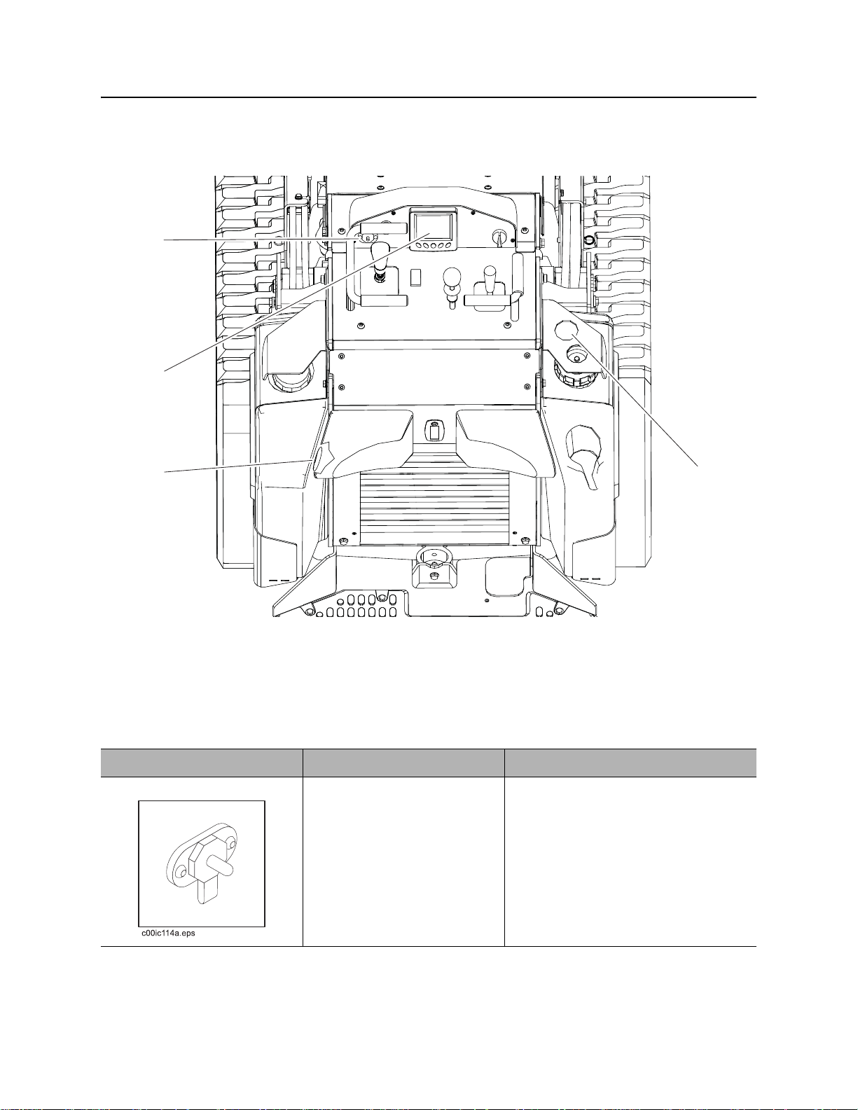
t43om004w.eps
1
3
2
4
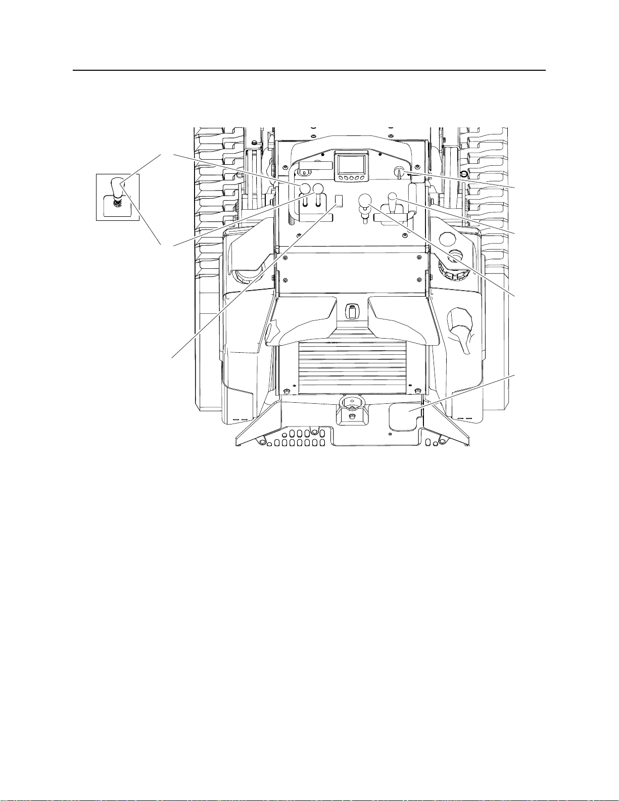
Gauges and Indicators
Gauges and Indicators
1. Auxiliary outlet
2. Graphic display
3. Hydraulic fluid level sight glass
4. Fuel gauge
Item Description Notes
1. Auxiliary outlet To operate work lights or
other 12V devices, plug into
outlet.
®
CMW
SK850 Operator’s Manual Controls - 23
c00ic098w.eps
c00ic099w.eps
c00ic100w.eps
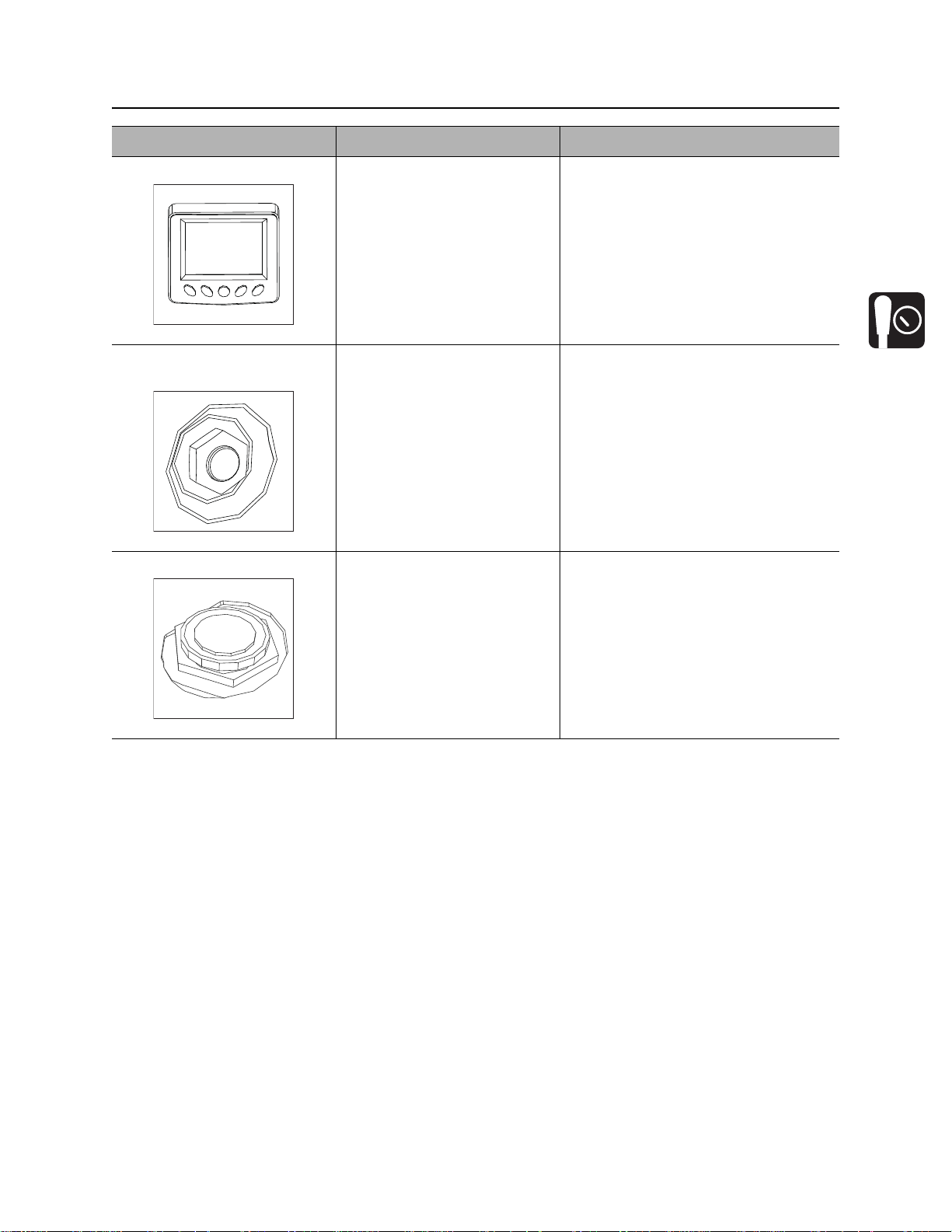
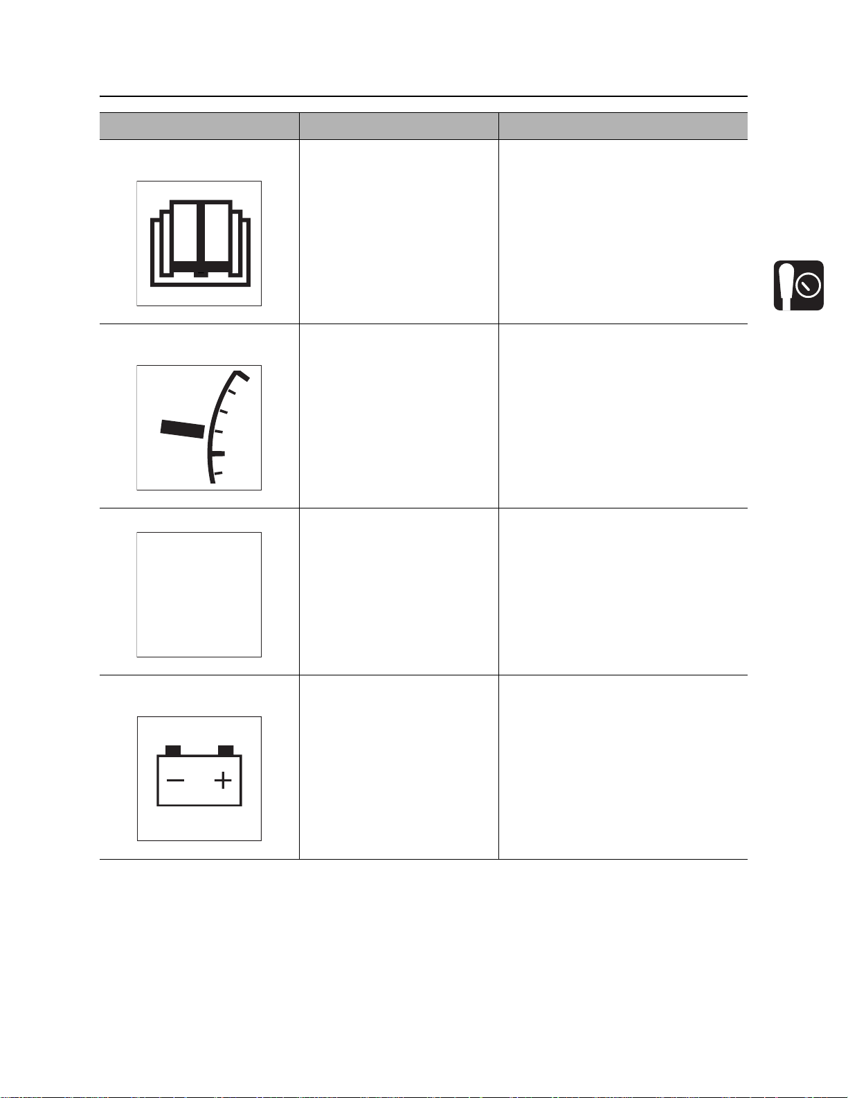
Gauges and Indicators
Item Description Notes
2. Graphic display See “Graphic Display” on
page 24.
3. Hydraulic fluid sight
glass
Shows level of hydraulic fluid
in tank. Maintain fluid at
halfway point on glass.
4. Fuel gauge Shows level of fuel in tank. NOTICE: Use low sulfur or ultra low
sulfur fuel only.
CMW
®
Controls - 24 SK850 Operator’s Manual
STOP
125
15 20
10
RPMx100
25
305
230
32
190
150
110
F
70
0
30
0
0.0V
Tier4
0
35
100
75
50
25
0
Engine
START UP
Load
0%
HRS
t43om026w.eps
123 4 56 7
8
9
10
11
12131415161718
19
20
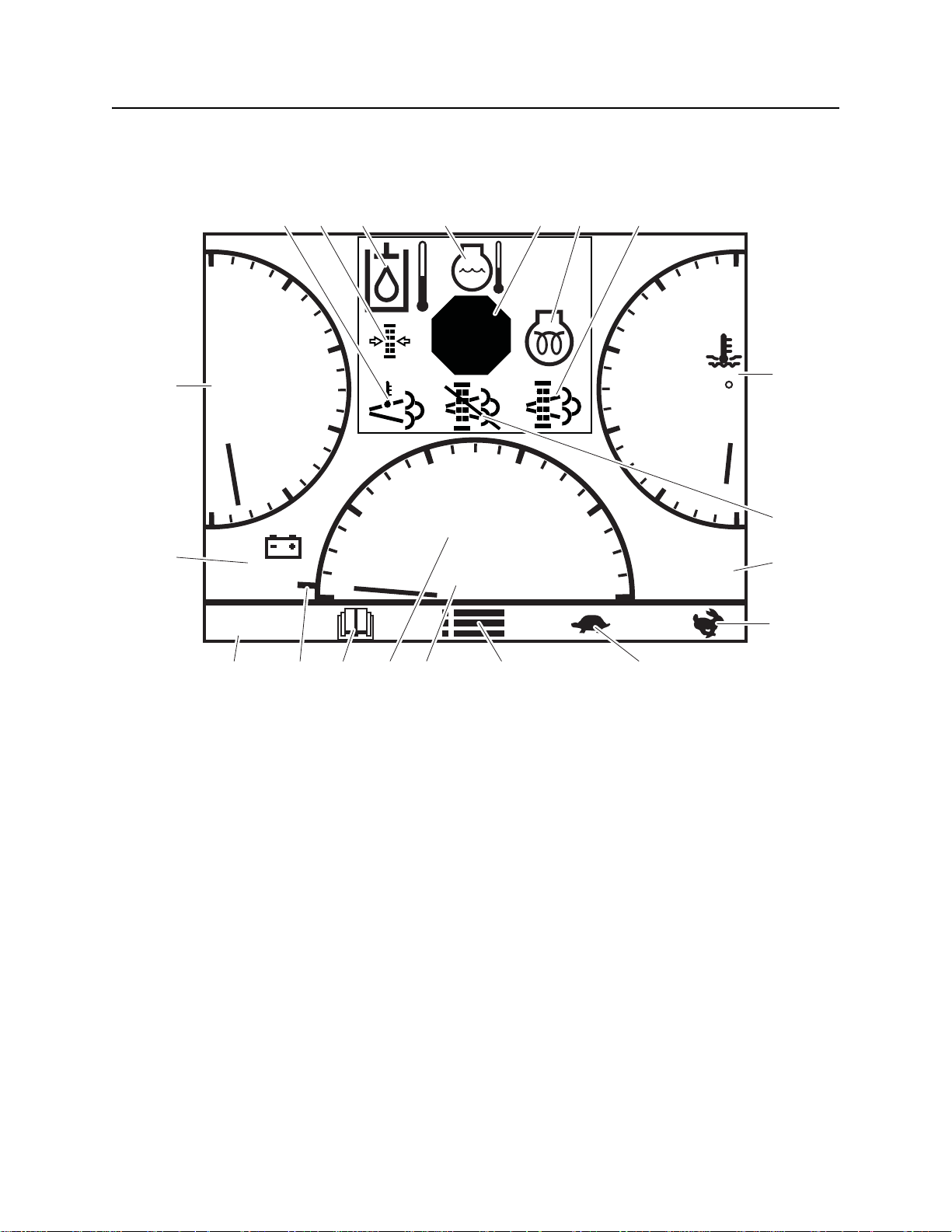
Graphic Display
Graphic Display
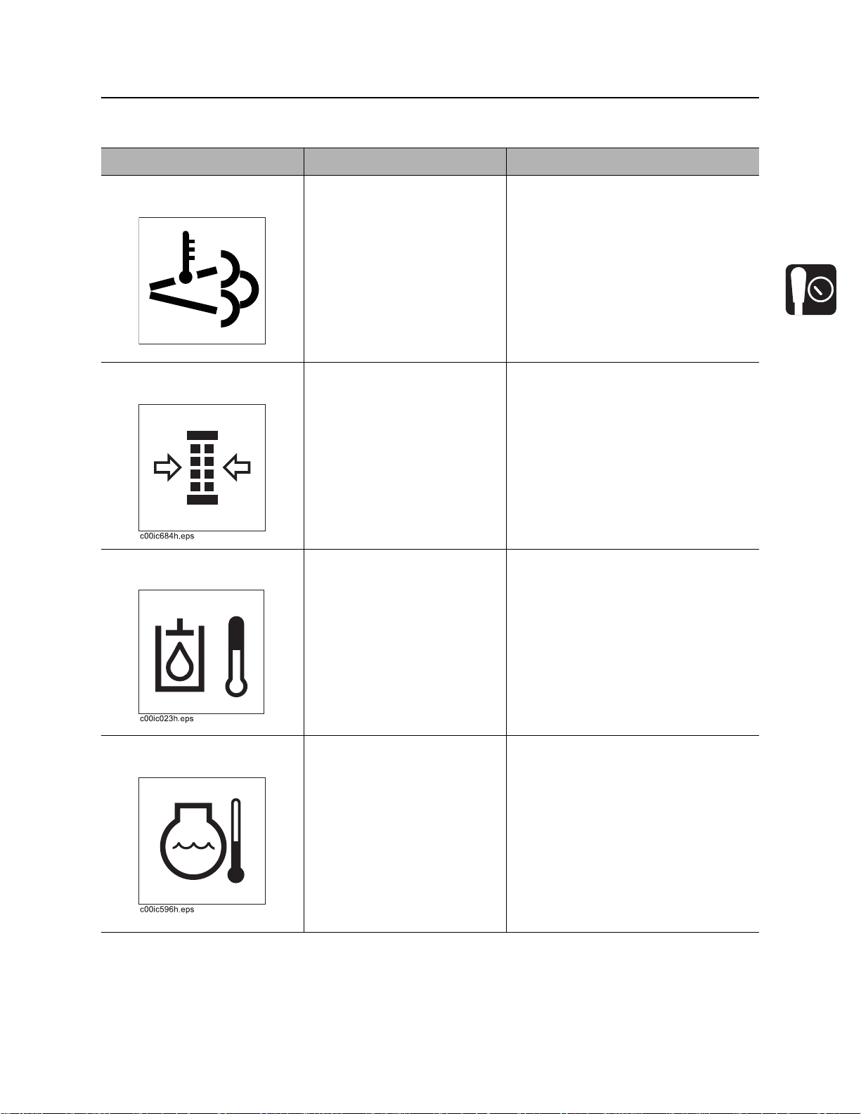
1. High exhaust temperature ind ica to r
2. Air filter restriction indicator
3. Hydraulic fluid temperature indicator
4. Engine over-temperature indica to r
5. Diagnostic message indicator
6. Glow plug indicator
7. DPF regeneration indicator
8. Engine coolant temperature indicator
9. DPF manual indicator
10. Hourmeter
CMW
®
11. Engine speed setpoint increase button
12. Engine speed setpoint decrease button
13. Menu button
14. Engine speed (RPM)
15. Throttle system state indicator
16. Service reminders button
17. Engine RPM setpoint indicator
18. Tier 4 menu button
19. Electrical system voltage
20. Engine percent load gauge
SK850 Operator’s Manual Controls - 25
c00ic101w.eps
Graphic Display
Item Description Notes
1. High exhaust
temperature indicator
2. Air filter restriction
indicator
3. Hydraulic fluid
temperature indicator
Indicates high exhaust
temperature.
Indicator will begin flashing
once the air filter is 25%
unrestricted. Percentage will
decrease as air filter
becomes more restricted.
For best results, replace filter
between 25% and 0%. Reset
after replacing air filter.
Lights and alarm sounds
when hydraulic fluid is
overheating.
IMPORTANT: Will light when DPF
regeneration is occurring.
T o view the air filter percentage before
25% unrestricted, press the
diagnostics menu button at any time.
Check hydraulic fluid level.
Reduce load.
4. Engine overtemperature indicator
Flashes when temperature
rises above 230°F (110°C).
Ensure oil cooler is clean.
IMPORTANT: If temperature goes
above 230°F (110°C):
1. Stop operation, set throttle to low
idle, and allow engine to cool.
2. Stop engine.
3. Check coolant level.
4. Ensure radiator is clean.
CMW
®
Controls - 26 SK850 Operator’s Manual
c00ic102w.eps
c00ic103w.eps
c00ic104w.eps
Graphic Display
Item Description Notes
5. Diagnostic message
indicator
Appears when there is a
diagnostic trouble code.
This indicates a warning
code.
This indicates a stop code.
6. Glow plug indicator Lights when ignition switch is
on and glow plug button is
pressed.
7. DPF regeneration
indicator
®
CMW
Will flash if regeneration is
needed but has not occurred
yet.
Will light if regeneration is
occurring.
SK850 Operator’s Manual Controls - 27
c00ic116w.eps
c00ic105w.eps
c00ic106w.eps
HRS
c00ic107w.eps
Graphic Display
Item Description Notes
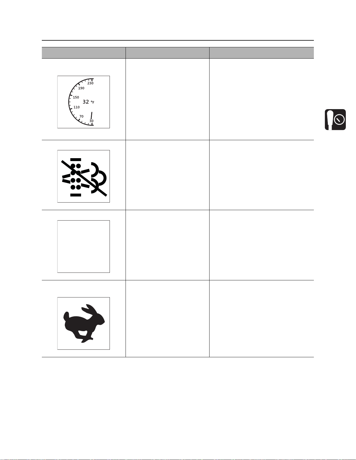
8. Engine coolant
temperature indicator
9. DPF manual indicator Will light when DPF
10. Hourmeter Displays engine operating
Displays coolant temperature. IMPORTANT: If temperature goes
regeneration has been
manually delayed.
time.
above 230°F (110°C):
1. Stop operation, set throttle to low
idle, and allow engine to cool.
2. Stop engine.
3. Check coolant level.
4. Ensure radiator is clean.
Use these times to schedule service.
11. Engine speed increase
button
To increase engine speed,
push.
IMPORTANT:
• Increasing engine speed also
increases attachment speed.
• Each button press increases
engine by 360 rpm.
• Press and hold the increase
button to automatically set engine
speed to high (3000 rpm).
CMW
®
Controls - 28 SK850 Operator’s Manual
c00ic108w.eps
c00ic109w.eps
c00ic110w.eps
c00ic111w.eps
STARTUP
AUTO
Graphic Display
Item Description Notes
12. E n gi n e sp e ed de cre as e
button
To decrease engine speed,
push.
13. Menu button Press to go to the menu
screen.
14. En gi n e sp e ed (RPM ) Displays engine RPM.
IMPORTANT: Each button press
decreases engine by 360 rpm.
15. Throttle system state
indicator
®
CMW
Displays one of the three
states of the throttle system.
• Startup indicates the system is
controlling its own throttle during
startup conditions.
• Auto indicates that the autothrottle system is active and
controlling engine throttle based
on the user’s selected rpm
setpoint. To enable auto-throttle,
go to the settings menu.
• No indication means that the rpm
setting is under manual control.
SK850 Operator’s Manual Controls - 29
c00ic112w.eps
c00ic113w.eps
c00ic114w.eps
Tier 4
c00ic008w.eps
Graphic Display
Item Description Notes
16. Service reminders
button
17. E n gi ne RPM setpoint
indicator
18. Tier 4 menu button Press to go to the DPF
Press to go to the service
reminders screen.
Indicates the current throttle
setpoint.
control menu.
IMPORTANT:
• When in manual throttle mode,
this is the RPM the engine will try
to maintain.
• When in auto-throttle mode, this
indicates the full throttle setpoint.
19. Electrical system
voltage
Displays system voltage. Should show 12-14V with engine
running.
CMW
®

Controls - 30 SK850 Operator’s Manual
c00ic115w.eps
Graphic Display
Item Description Notes
20. E n gi n e pe rce n t lo ad
gauge
Displays the load on the
engine.
IMPORTANT: Running the unit with
the engine load at 100% for an
extended time will cause the engine to
stall.
CMW
®

SK850 Operator’s Manual Controls - 31
ENGINE
INTERVAL 0
REMAINING 0
HRS
HRS
HOUR ENG HRS
RESET
1
2
3
4
5
768910
t43om032w.eps
Service Interval Screen
Service Interval Screen
1. Selected service reminder
2. Service reminder interval
3. Time remaining
4. Time base calculator
5. Reset option
6. Return to main gauge display
7. Interval decrease
8. Interval increase
9. Up selection
10. Down selection
Item Description Notes
1. Selected service
reminder
Displays current service
reminder.
2. Service reminder
interval
3. Time remaining Displays time remaining until
Displays current interval of
the service reminder.
the next service reminder.
Service reminders are programmed to
follow initial service reminders. See
the Service chapter on page 67 for
intervals.
®
CMW

Controls - 32 SK850 Operator’s Manual
c00ic121w.eps
c00ic120w.eps
c00ic119w.eps
c00ic118w.eps
Service Interval Screen
Item Description Notes
4. Time base calculator Displays the time base for the
service reminder.
5. Reset option Resets service reminder.
6. Return to main gauge
display
Returns to the main gauge
display.
7. Interval decrease Selects the previous reminder
or parameter, or decreases
service intervals by 10 hours.
8. Interval increase Selects the next reminder or
parameter, or increases
service interval by 10 hours.
IMPORTANT: Use the Service
chapter beginning on page 67 to set
service reminder intervals.
9. Up selection Will move the selection on the
screen up.
®
CMW

SK850 Operator’s Manual Controls - 33
c00ic117w.eps
Service Interval Screen
Item Description Notes
10. Do w n selection Will move the selection on the
screen down.
CMW
®
Controls - 34 SK850 Operator’s Manual
t43om005w.eps
1
2
3
6
5
4
7
Controls
Controls
1. Left track drive control or
Track drive joystick (optional)
2. Right track drive control or
Track drive joystick (optional)
3. Parking brake switch
®
CMW
4. Ignition switch
5. Lift arm control
6. Attachment drive control
7. Attachment drive foot control

SK850 Operator’s Manual Controls - 35
c00ic097w.eps
Controls
Item Description Notes
1. Left track drive control
2. Right track drive
control
Track drive joystick
(optional)
To move forward, push.
To move backward, pull.
To go faster in either
direction, move control farther
from neutral position.
To stop, move to neutral
position.
To move forward, push.
To move backward, pull.
To go faster in either
direction, move control farther
from neutral.
To stop, move to neutral.
To turn right, move left control farther
forward than right control.
To turn left, move right control farther
forward than left control.
To counter-rotate in either direction,
move controls in opposite directions
as indicated above.
To steer while moving forward, push
joystick forward, then move left or
right. Unit will gradually turn left or
right.
To steer while moving backward, pull
joystick back, then move left or right.
Unit will gradually turn left or right.
For tight steering in low speed, move
joystick to center position then to left
or right side. Tracks will counter rotate
and turn unit in a tight circle.
3. Parking brake switch To engage, move red switch
toward operator and press
back of switch down.
To disengage, move red
switch toward operator and
press front of switch down.
IMPORTANT:
• Only apply parking brake when
unit is at rest.
• Parking brake disengages
hydraulics.
CMW
®

Controls - 36 SK850 Operator’s Manual
Controls
Item Description Notes
4. Ignition switch T o star t engine, insert key and
turn clockwise.
To stop engine, turn key
counterclockwise.
5. Lift arm control To move lift arms down, push.
To float, push forward to end.
To move lift arms up, pull.
To curl attachment up, move
to left.
To curl attachment down,
move to right.
6. Attachment drive
control
To engage attachment drive
in reverse, lift lever lock and
push forward.
To engage attachment drive
in forward, lift lever lock and
pull back.
IMPORTANT:
• If engine does not start or stalls,
turn key to STOP and then
restart.
• Do not allow starter motor to run
continuously for more than 20
seconds.
IMPORTANT: Exercise caution when
lifting loads. See page 98 for
operating capacities.
IMPORTANT: If unit is equipped with
TR50 trencher, this will raise and
lower boom.
IMPORTANT:
• Lever lock engages when control
is in neutral.
• Use foot pedal to hold attachment
control in the on position when
hands are busy operating lift arm
or track drive controls.
7. Attachment drive foot
control
®
CMW
To hold attachment drive in
engaged position (forward or
reverse), lift lever lock, move
lever in desired direction, and
press pedal.
To return attachment drive
control to neutral, release
pedal.
IMPORTANT: Use foot pedal to hold
attachment control in the on position
when hands are busy operating lift
arm or track drive controls.

SK850 Operator’s Manual Controls - 37
t43om029w.eps
1
Engine Compartment
Engine Compartment
1. Battery disconnect switch
Item Description Notes
1. Battery disconnect
switch
To connect, turn clockwise.
To disconnect, turn
counterclockwise.
CMW
®

Controls - 38 SK850 Operator’s Manual
t43om034w.eps
1
2
Tool Carrier
Tool Carrier
1. Level indicator 2. Attachment latches
Item Description Notes
1. Level indicator To level bucket, adjust bucket
position until indicator is at
top of sleeve.
2. Attachment latches To lock attachment, move
latch down.
To unlock attachment, move
latch up.
®
CMW
To level other attachments, adjust
attachment position until it is level.
Mark indicator position on sleeve. Use
mark to indicate level with that
attachment.

SK850 Operator’s Manual Prepare - 39
Prep are
Chapter Contents
Gather Information . . . . . . . . . . . . . . . . . . . . . . . . . 40
Inspect Site . . . . . . . . . . . . . . . . . . . . . . . . . . . . . . . 41
• Identify Hazards . . . . . . . . . . . . . . . . . . . . . . . . . . . . . . . . . . . . . . . . . . .41
Classify Jobsite . . . . . . . . . . . . . . . . . . . . . . . . . . . 42
• Inspect Jobsite . . . . . . . . . . . . . . . . . . . . . . . . . . . . . . . . . . . . . . . . . . . .42
• Select a Classification . . . . . . . . . . . . . . . . . . . . . . . . . . . . . . . . . . . . . .42
• Apply Precautions . . . . . . . . . . . . . . . . . . . . . . . . . . . . . . . . . . . . . . . . .43
Check Supplies and Prepare Equipment . . . . . . . 44
• Supplies . . . . . . . . . . . . . . . . . . . . . . . . . . . . . . . . . . . . . . . . . . . . . . . . .44
• Fluid Levels . . . . . . . . . . . . . . . . . . . . . . . . . . . . . . . . . . . . . . . . . . . . . .44
• Condition and Function . . . . . . . . . . . . . . . . . . . . . . . . . . . . . . . . . . . . .44
• Accessories . . . . . . . . . . . . . . . . . . . . . . . . . . . . . . . . . . . . . . . . . . . . . .44
Connect Attachment . . . . . . . . . . . . . . . . . . . . . . . 45
CMW
®

Prepare - 40 SK850 Operator’s Manual
Gather Information
Gather Information
A successful job begins before you start working. The fi rst step in planning is reviewing information already
available about the job and jobsite.
Review Job Plan
Review blueprints or other plans. Check for information about exi sting or planned structur es, elevations, or
proposed work that may be taking place at the same time.
Arrange for Traffic Control
If working near a road or other traffic area, contact local authorities about safety procedures and
regulations.
Plan for Emergency Services
Have the telephone numbers for local emergency and medical facilities on hand. Check that you will have
access to a telephone.
Notify One-Call Services
Contact your local One-Call (811 in USA) or the One-Call referral number (888-258-0808 in USA and
Canada) to have underground utilities located before digging. Also contact any utilities that do not
participate in the One-Call service.
Locate Overhead Lines
Note location and height of all overhead lines in jobsite and ensure that fully lifted attachment and/or load
cannot touch lines.
CMW
®
SK850 Operator’s Manual Prepare - 41
Inspect Site
Inspect Site
Inspect jobsite before transporting equipment. Check for the following:
• changes in elevation such as hills or other open trenches
• obstacles such as buildings, railroad crossings, or streams
• signs of utilities (See “Inspect Jobsite” on page 42.)
•traffic
•access
• soil type and condition
Identify Hazards
Identify safety hazards and classify jobsite if attachment will penetrate ground. See “Classify Jobsite” on
page 42.
Jobsite hazards could cause death or serious injury. Use
correct equipment and work methods. Use and maintain proper safety
equipment.
To help avoid injury:
• Wear personal protective equipment including hard hat, safety eye wear, and hearing protection.
• Do not wear jewelry or loose clothing.
• Notify One-Call and companies which do not subscribe to One-Call.
• Comply with all utility notification regulations before digging or drilling.
• Verify location of previously marked underground hazards.
• Mark jobsite clearly and keep spectators away.
Remember, jobsite is classified by hazards in place -- not by line being installed.
CMW
®

Prepare - 42 SK850 Operator’s Manual
Classify Jobsite
Classify Jobsite
Inspect Jobsite
• Inspect jobsite and perimeter for evidence of underground hazards, such as:
– “buried utility” notices
– utility facilities without overhead lines
– gas or water meters
– junction boxes
– drop boxes
– light poles
– manhole covers
– sunken ground
• Follow U.S. Department of Labor regulations on excavating and trenching (Part 1926, Subpar t P) and
other similar regulations.
• Contact your local One-Call (811 in USA) or the One-Call referral number (888-258-0808 in USA and
Canada) to have underground utilities located before digging. Also contact any utilities that do not
participate in the One-Call service.
• Have an experienced locating equipment operator sweep area within 20’ (6 m) to each side of work
path. Verify previously marked line and cable locations.
• Mark location of all buried utilities and obstructions.
• Classify jobsite.
Select a Classification
Jobsites are classified according to underground hazards present.
If working . . . then classify jobsite as . . .
within 10’ (3 m) of a buried electric line electric
within 10’ (3 m) of a natural gas line natural gas
in sand or granite which is capable of producing crystalline silica
(quartz) dust
within 10’ (3 m) of any other hazard other
NOTICE: If you have any doubt about jobsite classification, or if jobsite might contain unmarked
hazards, take steps outlined previously to identify hazards and classify jobs ite be fo re wor kin g.
crystalline silica (quartz) dust
CMW
®
SK850 Operator’s Manual Prepare - 43
Classify Jobsite
Apply Precautions
Once classified, precautions appropriate for jobsite must be taken.
Electric Jobsite Precautions
Use one or both of these methods.
• Expose line by careful hand digging or soft excavation.
• Have service shut down while work is in progress. Have electric company test lines before returning
them to service.
Natural Gas Jobsite Precautions
In addition to positioning equipment upwind from gas lines, use one or both of these methods.
• Expose lines by careful hand digging or soft excavation.
• Have gas shut off while work is in progress. Have gas company test lines before returning them to
service.
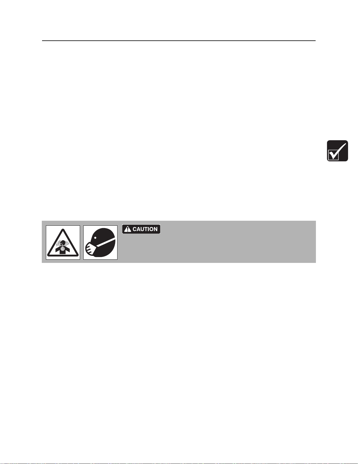
Crystalline Silica (Quartz) Dust Precautions
Use breathing protection when exposed to silica dust.
270-4952
Cutting, drilling, or working materials such as concrete, sand, or rock containing quartz may result in
exposure to silica dust. Use water spray or other means to control dust. If workers are exposed to dust
they must wear appropriate breathing protection. Silica dust may cause lung disease and is known to the
State of California to cause cancer.
Other Jobsite Precautions
You may need to use different methods to safely avoid other underground hazards. Talk with those
knowledgeable about hazards present at each site to determine which precautions should be taken or if
job should be attempted.
CMW
®

Prepare - 44 SK850 Operator’s Manual
Check Supplies and Prepare Equipment
Check Supplies and Prepare Equipment
Supplies
•fuel
NOTICE: Use low sulfur or ultra low sulfur fuel only.
•keys
•lubricants
• personal protective equipment, such as hard hat and safety glasses
Fluid Levels
•fuel
NOTICE: Use low sulfur or ultra low sulfur fuel only.
• hydraulic fluid
• battery charge
• engine oil
Condition and Function
• parking brake pins (See “Check Brake Operation” on page 73.)
• filters (air, oil, hydraulic)
•tracks
• pumps and motors
• hoses and valves
• signs, guards, and shields
Accessories
Fire Extinguisher
If required, mount a fire extinguisher near the power unit but away from possible points of ignition. The fire
extinguisher should always be classified for both oil and electric fires. It should meet legal and regulatory
requirements.
CMW
®

SK850 Operator’s Manual Prepare - 45
t05om026c.eps
12
Connect Attachment
Connect Attachment
NOTICE: Use only Ditch Witch®-approved attachments. Attachments can change the stability and
operating characteristics of the unit. See attachment operatio n man ual for instructions rega rd ing p roper
operation of attachments.
Attachment
IMPORTANT: Before connecting attachment to unit,
ensure that mount and receiver plates are free of dirt
and debris.
1. Position attachment on level surface with enough
space behind it to accommodate unit.
2. Start engine.
3. Tilt mount plate (2) forward.
4. Position mount plate in the upper lip of the receiver
plate (1) on attachment.
5. Raise lift arms while tilting back mount plate.
IMPORTANT: Attachment should be raised
enough to clear the ground. Mount plate
should be tilted back fully.
6. Pins will automatically engage.
Read operator’s manual. Know how to use all controls.
Your safety is at stake.
T o help avoid injury: Ensure pro per connection by ve rifying that bo ttoms
of lock pins are visible under attachment receiver plate (shown).
t43om006w.eps
®
CMW

Prepare - 46 SK850 Operator’s Manual
Connect Attachment
7. Ensure pins are engaged by rotating
attachment down.
t43om007w.eps
CMW
®

SK850 Operator’s Manual Prepare - 47
2
1
3
t35om011w.eps
2
1
3
Connect Attachment
Hydraulic Hoses
If attachment requires hydraulic power for operatio n , con ne ct hyd ra ulic ho se s.
Pressurized fluid or air could pierce skin and cause
severe injury. Refer to operator’s manual for proper use.
To help avoid injury:
• Escaping pressurized fluid can cause injury or pierce skin and poison.
• Before disconnecting a hydraulic line, turn engine off and ope rate all controls to relieve pressure.
Lower, blo ck, or support any raised component with a hoist. Cover connection with heavy clo th and
loosen connector nut slightly to relieve residual pressure. Catch all fluid in a container.
• Before using system, check that all connections are tight and all lines are undamaged.
• Use a piece of cardboard or wood, rather than hands, to search for leaks.
• Wear protective clothing, including gloves and eye protection.
• If you are injured, seek immediate medical attention from a doctor familiar with this type of injury.
Hot parts may cause burns. Do not touch until cool.
To help avoid injury: Wear gloves when connecting and disconnecting
hydraulic hoses and wait until unit has cooled before touching hydraulic
components.
1. Cycle attachment drive control to relieve
residual pressure at hydraulic couplers.
2. Remove dirt and debris from hydraulic
couplers.
3. Connect male coupler on attachment to female
coupler (3) on unit.
4. Connect female coupler on attachment to male
coupler (1) on unit.
5. If needed, connect attachment case drain hose
to case drain connector (2).
6. Ensure that connections are secure by pulling
on hoses.
®
CMW

Prepare - 48 SK850 Operator’s Manual
Connect Attachment
CMW
®

SK850 Operator’s Manual Drive - 49
Drive
Chapter Contents
Start Unit . . . . . . . . . . . . . . . . . . . . . . . . . . . . . . . . . 50
Drive. . . . . . . . . . . . . . . . . . . . . . . . . . . . . . . . . . . . . 50
Shut Down. . . . . . . . . . . . . . . . . . . . . . . . . . . . . . . . 52
CMW
®

Drive - 50 SK850 Operator’s Manual
Start Unit
Start Unit
1. Ensure all controls are in neutral.
2. If necessary, use glow plugs to warm cold engine.
3. Move throttle to half open.
4. Turn ignition switch to start position and release when engine starts.
EMERGENCY SHUTDOWN: Turn ignition switch to STOP.
Drive
General Operation
Tipover possible. Machine can tip over and crush you.
To help avoid injury:
• Always operate with load end uphill.
• Always carry load low. High load can cause tipping, loss of load or loss of
visibility.
• Never jerk control levers. Use a steady even motion.
• See page 98 for operating capacity.
1. Disengage parking brake.
2. Pull lift arm control to raise mount plate (and attachment) off gro und.
3. Move track drive control to steer unit. See page 35.
IMPORTANT: If needed for attachment operation, push attachment drive foot control to hold
attachment control in the forward position while operating track drive and lift arm controls.
4. Adjust throttle as needed.
5. See attachment operation manual for instructions regarding proper operation of attachments.
CMW
®

SK850 Operator’s Manual Drive - 51
Drive
Safe Slope Operation
Tipover possible. Machine can tip over and crush you.
To help avoid injury:
• Always operate with heavy end uphill.
• Always carry load low. High load can cause tipping, loss of load or loss of
visibility.
• Drive cautiously at all times.
• Never jerk control levers. Use a steady even motion.
• Do not park unit on slope without lowering attachment to the ground,
returning all controls to neutral position, shutting down unit, and applying
parking brake.
• See page 98 for operating capacity.
Operating safely on a slope depends upon many factors including:
• Distribution of machine weight, including front loading and absence of load
• Height of load
• Even or rough ground conditions
• Potential for ground giving way causing unplanned tilt forward, reverse or sideways
• Nearness of ditches, ruts, stumps or other obstructions and sudden changes in slope
• Speed
• Turning
• Braking performance
• Operator skill
These varying factors make it impractical to specify a maximum safe operating angle in this manual. It is
therefore important for the operator to be awa re of these conditions and adjust operation accordingly.
Maximum engine angle and braking performance are two absolute limits which must never be exceeded.
These maximums are stated below since they are design limit s. T hese desig n limits usually exceed the
operating limits and must never be used alone to establish safe operating angle for variable
conditions.
Maximum engine lubrication angle – 20°
Maximum service brake retarding force – equal to traction of both tracks.
Maximum park brake holding force – equal to traction of one track.
CMW
®

Drive - 52 SK850 Operator’s Manual
Shut Down
Shut Down
1. Lower lift arms to ground.
2. Move all controls to neutral position.
3. Engage parking brake.
4. Turn ignition switch to STOP.
5. Remove key.
CMW
®

SK850 Operator’s Manual Transport - 53
Transport
Chapter Contents
Lift . . . . . . . . . . . . . . . . . . . . . . . . . . . . . . . . . . . . . . 54
• Points . . . . . . . . . . . . . . . . . . . . . . . . . . . . . . . . . . . . . . . . . . . . . . . . . . .54
• Procedure . . . . . . . . . . . . . . . . . . . . . . . . . . . . . . . . . . . . . . . . . . . . . . . .55
Haul . . . . . . . . . . . . . . . . . . . . . . . . . . . . . . . . . . . . . 56
• Load . . . . . . . . . . . . . . . . . . . . . . . . . . . . . . . . . . . . . . . . . . . . . . . . . . . .56
• Tie Down . . . . . . . . . . . . . . . . . . . . . . . . . . . . . . . . . . . . . . . . . . . . . . . .57
• Unload . . . . . . . . . . . . . . . . . . . . . . . . . . . . . . . . . . . . . . . . . . . . . . . . . .58
Tow . . . . . . . . . . . . . . . . . . . . . . . . . . . . . . . . . . . . . 59
CMW
®

Transport - 54 SK850 Operator’s Manual
Lift
Lift
Crushing weight. If load falls or moves it could kill or crush
you. Use proper procedures and equipment or stay away.
To help avoid injury: Only lift unit without attachment installed.
Points
Lifting points are identified by lifting decals. Lifting at other points is unsafe
and can damage machinery.
CMW
®

SK850 Operator’s Manual Transport - 55
Lift
Procedure
Use a hoist capable of supporting the
equipment's size and weight. See
“Specifications” on page 97 or measure and
weigh equipment before lifting.
Use one of the methods below:
• Use two points nearest operator station.
IMPORTANT: Front of unit will be lower than
rear of unit when using only two lift points.
• Use three lift points as shown.
NOTICE: Do not lift unit with attachments
installed.
t43om008w.eps
CMW
®

Transport - 56 SK850 Operator’s Manual
Haul
Haul
Load
Crushing weight. If load falls or moves it could kill or crush
you. Use proper procedures and equipment or stay away.
To help avoid injury:
• Load and unload trailer on level ground.
• Incorrect loading can cause trailer swaying.
• Attach trailer to vehicle before loading or unloading.
• Only operate unit from operator platform.
• To help prevent trailer sway, load trailer so that ten to fifteen percent of total vehicle weight
(equipment plus trailer) is on tongue.
• If loading onto tilt-bed trailer, be prepared for trailer to tilt.
• Move all controls to neutral position when stopped.
1. Disengage parking brake.
2. Start engine.
3. Adjust throttle to low speed.
4. Pull lift arm control to raise mount plate (and attachment) clear of trailer, but keep it low.
5. Move unit to rear of trailer and align with ramps.
6. Drive forward slowly to move unit onto trailer until tiedown position is reached.
7. Push lift arm control to lower mount plate (and attachment) to trailer bed.
8. Engage parking brake.
9. Ensure that all controls are in neutral position.
10. Turn ignition switch to STOP.
11. Tie down unit.
CMW
®

SK850 Operator’s Manual Transport - 57
t43om009w.eps
Haul
Tie Down
Points
Tiedown points are identified by tiedown decals. Securing to truck or trailer
at other points is unsafe and can damage machinery.
Procedure
Loop tiedowns around unit at tiedown points. Make sure tiedowns are tight before transporting.
CMW
®

Transport - 58 SK850 Operator’s Manual
Haul
Unload
Crushing weight. If load falls or moves it could kill or crush
you. Use proper procedures and equipment or stay away.
To help avoid injury:
• Load and unload trailer on level ground.
• Attach trailer to vehicle before loading or unloading.
• Only operate unit from operator platform.
• If unloading from tilt-bed trailer, be prepared for trailer to tilt.
1. Prepare trailer and ramp s for unloading.
2. Remove tiedowns.
3. Start engine.
4. Disengage parking brake.
5. Pull lift arm control to raise mount plate (and attachment) off gro und, but keep it low.
6. Adjust throttle to low speed and slowly back unit down trailer or ramps.
CMW
®

SK850 Operator’s Manual Transport - 59
t43om010w.eps
rear tow point front tow point
Tow
Tow
Read operator’s manual. Know how to use all controls.
Your safety is at stake.
Under normal conditions, unit should not be towed. If unit breaks down and towing is necessary:
273-475
• attach chains to tow points facing towing vehicle
• tow for short distances at less than 1 mph (1.6 km/h)
• do not tow for more than 100’ (30 m)
• use no more than 1,300 lb (5800 N) of towing force
• open bypass valve on each pump section
NOTICE: When bypass valve is open, unit has no brakes.
• if engine will not start, remove rear panel and unbolt parking brake assembly
CMW
®

Transport - 60 SK850 Operator’s Manual
Tow
Prepare Unit for Towing
1. Block tracks.
2. Engage parking brake (shown).
t43om012w.eps
3. Loosen bypass valves (shown) three turns.
IMPORTANT: Open bypass valves in both
front and rear pumps.
NOTICE: When bypass valves are open, unit
has no brakes.
t43om030w.eps
Return Unit to Normal Operation
1. Tighten bypass valves and tighten locknut to 15-18 ft•lb (20-25 N•m).
IMPORTANT: Close bypass valve in both front and rear pumps.
2. Disengage parking brake.
3. Unblock tracks.
CMW
®

SK850 Operator’s Manual Trench - 61
Trench
Chapter Contents
Setup . . . . . . . . . . . . . . . . . . . . . . . . . . . . . . . . . . . . 62
Operation. . . . . . . . . . . . . . . . . . . . . . . . . . . . . . . . . 63
CMW
®

Trench - 62 SK850 Operator’s Manual
Setup
Setup
EMERGENCY SHUTDOWN - Turn ignition switch to STOP.
Crushing weight could cause death or serious injury. Use
proper procedures and equipment or stay away.
T o help avoid injury: Use attachments or counterweights to make front and rear loads balance when all
®
attachments are raised. Contact your Ditch Witch
correct equipment and work methods. Use and maintain proper safety
equipment.
dealer about counterweighting for your equipment.
Jobsite hazards could cause death or serious injury. Use
To help avoid injury: Comply with all utility notification regulations before digging or drilling.
Read operator’s manual. Know how to use all controls.
Your safety is at stake.
1. Start unit. See page 50 for start-up procedures.
2. Drive to starting point. Move in line with planned trench. See page 50 for operating procedures.
IMPORTANT:
• When cutting asphalt, start trench in soil at edge of road an d use sh or te st po ssib l e boo m at
full depth.
• Sight along center of hood to a stake driven beyond end of trench line for straight trench.
3. Engage parking brake.
4. Lower boom to just above ground.
5. Check that attachment speed/direction control and ground drive controls are in neutral.
273-475
CMW
®

SK850 Operator’s Manual Trench - 63
6ft/2m
Setup
Operation
Use breathing protection when exposed to silica dust.
270-4952
Electrical shock. Contacting electrical lines will cause death or serious
injury. Know location of lines and stay away.
To help avoid injury: Expose lines by hand before digging. Cutting high voltage cable can cause
electrocution.
Read operator’s manual. Know how to use all controls.
Your safety is at stake.
273-475
To help avoid injury:
• Comply with all utility notification regulations before digging or drilling.
• Notify companies that do not subscribe to One-Call.
Flying objects thrown by machine may strike people.
Wear hard hat and safety glasses.
275-193
Moving digging teeth will cause death or serious injury.
Stay away.
275-097
To help avoid injury:
• Ensure parking brake is engaged.
• Allow 3’ (1 m) between digging teeth and obstacle. Machine might jerk when digging starts.
• Keep everyone at least 6’ (2 m) from machine, attachments, and their range of movement.
1. Adjust throttle to low idle.
CMW
®

Trench - 64 SK850 Operator’s Manual
t43om033w.eps
Setup
2. Engage attachment control.
3. Increase engine speed to full throttle.
4. Slowly lower digging boom to depth.
5. Move ground drive control to desired speed.
6. Pull ground drive control rearward to desired
trenching speed. Trenching movement is
toward you.
NOTICE:
• Do not make sharp turns. Lower
boom to full depth when turning.
• If an object becomes lodged in chain,
move attachment speed/direction
control to neutral and raise boom
slightly. Reverse chain direction. If
object must be removed manually,
turn engine off and engage parking
brake.
7. When trench is complete, move ground drive control to neutral.
8. Adjust throttle to low idle.
9. Raise boom.
10. As boom clears top of trench, move attachment speed/direction control to neutral.
11. Drive a short distance away from work site.
12. Shut down unit. See page 52 for proper shutdown procedures.
CMW
®

SK850 Operator’s Manual Complete the Job - 65
Complete the Job
Chapter Contents
Rinse Equipment . . . . . . . . . . . . . . . . . . . . . . . . . . 66
Disconnect Attachment . . . . . . . . . . . . . . . . . . . . . 66
Stow Tools . . . . . . . . . . . . . . . . . . . . . . . . . . . . . . . 66
CMW
®

Complete the Job - 66 SK850 Operator’s Manual
Rinse Equipment
Rinse Equipment
1. Spray water onto equipment to remove dirt and mud.
NOTICE: Do not spray wa ter onto operator’s console. Electrical compone nts could be damaged .
Wipe down instead.
2. Open hood and allow unit to cool. Remove debris from inside of unit.
3. Remove mud from track sprockets.
4. Wash undercarriage. Pay special attention to brake pin area.
Disconnect Attachment
1. Lower attachment to the ground.
2. Turn off engine.
3. Disengage lock pins by lifting handles upward.
4. Cycle attachment drive control and disconnect hydraulic hoses, if used.
5. Start engine.
6. Tilt mount plate forward and back unit away from attachment.
Stow Tools
Make sure all tools and accessories are loaded and properly secured on trailer.
CMW
®

SK850 Operator’s Manual Service - 67
Service
Chapter Contents
Precautions . . . . . . . . . . . . . . . . . . . . . . . . . . . . . . 68
• Working under Raised Lift Arms . . . . . . . . . . . . . . . . . . . . . . . . . . . . . . .68
• Welding Precaution. . . . . . . . . . . . . . . . . . . . . . . . . . . . . . . . . . . . . . . . .68
Overview . . . . . . . . . . . . . . . . . . . . . . . . . . . . . . . . . 69
Recommended Lubricants/Service Key . . . . . . . . 69
Engine Oil Temperature Chart . . . . . . . . . . . . . . . 70
10 Hour . . . . . . . . . . . . . . . . . . . . . . . . . . . . . . . . . . 72
50 Hour . . . . . . . . . . . . . . . . . . . . . . . . . . . . . . . . . . 79
200 Hour. . . . . . . . . . . . . . . . . . . . . . . . . . . . . . . . . . 82
500 Hour . . . . . . . . . . . . . . . . . . . . . . . . . . . . . . . . . 84
2000 Hour . . . . . . . . . . . . . . . . . . . . . . . . . . . . . . . . 86
As Needed . . . . . . . . . . . . . . . . . . . . . . . . . . . . . . . 87
CMW
®

Service - 68 SK850 Operator’s Manual
t35om037w.eps
Precautions
Precautions
Read operator’s manual. Know how to use all controls.
Your safety is at stake.
To help avoid injury:
• Unless otherwise instructed, all service should be performed with engine off.
• Before servicing equipment, lower unstowed attachments to ground.
Working under Raised Lift Arms
Crushing weight. Place cylinder lock on extended cylinder
and secure.
273-231
273-475
Use safety supports as indicated when working
under raised lift arms.
Welding Precaution
NOTICE: Welding can damage electronics.
• Disconnect battery to prevent damage to battery. Do not turn off battery disconnect switch with
engine running, or alternator and other electronic devices may be damaged.
• Connect welder ground clamp close to welding point and make sure no electronic components are
in the ground path.
• Always disconnect the Engine Control Unit ground connection from the frame, harness conne ctions
to the ECU, and other electronic components prior to welding on machine or attachments.
®
CMW

SK850 Operator’s Manual Service - 69
500 h
200 h
50 h
10 h
Overview
Overview
Recommended Lubricants/Service Key
Item Description
DEO Diesel engine oil meeting API service classification CF-4 or E1-96 and SAE viscosity
recommended by engine manufacturer (SAE 15W40)
THF
MPG Multipurpose grease meeting NLGI GC-LB Grade 2
Proper lubrication and maintenance protects Ditch Witch® equipment from damage and failure. Service
intervals listed are for minimum requirements. In ex treme conditions, service machine more frequently.
Use only genuine Ditch Witch parts, filters, approved lubricants, TJC, and approved coolants to maintain
warranty. Fill to capacities listed in “Specifications” on page 71.
Tractor hydraulic fluid, similar to Phillips 66
Hydraulic Fluid, Texaco
Check level of fluid or lubricant Check condition
Filter Change, replace, adjust, service or
®
TDH Oil, or equivalent
®
HG, Mobilfluid® 423, Chevron® Tractor
test
CMW
®

Service - 70 SK850 Operator’s Manual
Temperature range anticipated before next oil change
SAE 10W
SAE 20W
SAE 5W - 30
SAE 10W - 30
SAE 15W - 40
SAE #20
SAE #30
SAE #40
t43om031w.eps
Engine Oil Temperature Chart
For more information on engine lubrication and maintenance, see your engine manual.
IMPORTANT: Use the “Service Record” on page 105 to record all required service to your machine.
Engine Oil Temperature Chart
For more information on engine lubrication and maintenance, see your engine manual.
Approved Coolants
This unit was filled with John Deere® Cool-Gard® coolant before shipment from factory. Add only CoolGard (p/n 255-006) or any fully-formulated, ethylene glycol based, low-silicate, heavy-duty diesel engine
coolant meeting ASTM specification D5345 (prediluted) or D4985 (concentrate). Before using any other
kind of coolant, completely flush radiator.
NOTICE: Do not mix heavy-duty diesel engine coolant and automotive-type coolant. This will lead
coolant breakdown and engine damage.
®
CMW

SK850 Operator’s Manual Service - 71
Engine Oil Temperature Chart
Approved Fuel
The engine is this unit is designed to run on diesel fuel. Use o nly high-quality fuel meeting ASTM D975 No.
2D, EN590, or equivalent. At temperatures below 32°F (0°C), winter fuel blends are acceptable. See
engine operation manual for more information.
IMPORTANT:
• For machines operated in the U.S.: The engine in this product is certified to operate on low sulfur
diesel fuel (LSD) with a sulfur content of 500 ppm (0.05%) or less. Use LSD or ultra low sulfur fuel
(ULSD) only. Using fuels with higher sulfur content will affect exhaust emissions. Such action is a
violation of the US Clean Air Act and US EPA regulations and will result in fines.
• For machines operated outside the U.S.: Fuel sulfur content shou ld be less than 5000 ppm (0.05%).
Worldwide fuel sulfur regulations vary widely. Fuel used should always comply with local
regulations. If fuel sulfur content exceeds 5000 ppm, use a lube oil meeting API CF (or equivalent)
with a TBN value of 10 or greater. Do not use lube oils meeting API CJ-4 (or other low SAPS
equivalent) under any conditions.
Biodiesel blends up to 5% (B5) are approved for use in this unit. The fuel must meet the specifications for
diesel fuel shown above. In certain markets, hig her blends may be used if certain steps are taken. Extra
attention is needed when using biodiesel, especially when operating in cold weather or storing fuel.
Contact your Ditch Witch
®
dealer or the engine manufacturer for more information.
CMW
®

Service - 72 SK850 Operator’s Manual
Startup/10 Hour
Startup/10 Hour
Location Task Notes
Check engine oil level DEO
Check engine air filter service indicator
Check engine coolant level DEAC
Check hydraulic fluid level THF
Check brake operation
Check track tension
Check lug nut torque 88-95 ft•lb (108-129 N•m)
Check hydraulic hoses
TR50 Lube auger bearing MPG
Check digging chain tension
Check restraint bar position MPG
Check Engine Oil Level
Check engine oil level at dipstick opening (1) at
startup and every 10 hours. Raise lift arms and
install safety supports. See “Working under
Raised Lift Arms” on page 68. Oil level should be
at top of marking. If low, add DEO at fill (2). Check
with unit on level surface and at least 15 minutes
after stopping engine.
IMPORTANT: Use oil specified in “Engine Oil
Temperature Chart” on page 70.
2
1
t35om009w.eps
CMW
®

SK850 Operator’s Manual Service - 73
Startup/10 Hour
Check Engine Air Filter Service
Indicator
Check air filter service indicator (shown) at
startup and every 10 hours and change filter as
needed. See “Change Air Filter” on page 87.
t35om010w.eps
Check Hydraulic Fluid Level
1
Check hydraulic fluid level at startup and every
10 hours. Maintain fluid level at halfway point on
sight glass (2), when engine is off, cylinders are
fully retracted, and fluid is cool. If low, add THF at
fill (1).
2
Check Brake Operation
Check brake operation at startup and every 10
hours or more often when conditions warrant.
• Ensure parking brake pin (shown) moves
freely allowing brake to be engaged and
disengaged.
• Clean mud and debris from area around pin.
t35om013w.eps
t35om014w.eps
CMW
®

Service - 74 SK850 Operator’s Manual
t35om036w.eps
t35om033w.eps
1
2
Startup/10 Hour
Check Lug Nut Torque
Check lug nut torque at 10 hours, 50 hours and
every 200 hours thereafter. Tighten to 88-95 ft•lb
(108-129 N•m) as needed.
Check Track Tension
Check track tension at startup and every 10
hours and adjust as needed. Track is correctly
tensioned when measurement between track and
straight edge (2) is 1/2 in (13 mm).
To adjust:
1. Park machine on smooth, flat surface.
2. Lay straight edge on top of track, spanning
from sprocket to front idler roller.
3. Clean track cylinder zerk (1). Pump MPG into
zerk until distance between track and straight
edge (2) is 1/2” (13 mm).
4. Test: Drive forward one track length and
check tension again.
• If tension is too loose, repeat step 3
above.
• If tension is too tight, loosen fitting on
grease cylinder and allow a small
amount of grease to discharge from
cylinder. Tighten fitting and test again.
CMW
®

SK850 Operator’s Manual Service - 75
t43om015w.eps
Startup/10 Hour
Check Coolant Level
Check coolant level, with engine cool, at overflow
bottle at startup and every 10 hours. Maintain
coolant level at halfway point on bottle. If low, add
approved coolant.
IMPORTANT: See page 70 for information on
approved coolants.
CMW
®

Service - 76 SK850 Operator’s Manual
Startup/10 Hour
Check Hydraulic Hoses
Pressurized fluid or air could pierce skin and cause severe
injury. Refer to operator’s manual for proper use.
To help avoid injury:
• Before disconnecting a hydraulic line, turn engine off and operate all controls to relieve pressure.
Lower, block, or support any raised component with a hoist. Cover connection with heavy cloth and
loosen connector nut slightly to relieve residual pressure. Catch all fluid in a container.
• Before using system, check that all connections are tight and all lines are undamaged.
• Use a piece of cardboard or wood, rather than hands, to search for leaks.
• Wear protective clothing, including gloves and eye protection.
• If you are injured, seek immediate medical attention from a doctor familiar with this type of injury.
270-6035
Check hydraulic hoses for leaks at startup and
every 10 hours.
CMW
®

SK850 Operator’s Manual Service - 77
t43om035w.eps
t43om036w.eps
Startup/10 Hour
TR50
Lube Auger Bearing
Lube auger bearing zerk with MPG every 10
hours.
Check Digging Chain Tension
Check digging chain tension every 10 hours and
adjust as needed. With boom horizontal, measure
distance A from bottom of boom to chain. When
properly tensioned, distance A should be 1.5-2.0”
(38-51 mm).
NOTICE: Do not overtighten chain.
Overtightening will cause chain stretch, loss
of machine performance, and possible
premature chain failure.
Adjustment Screw:
1. Loosen four clamp bolts (2) so that boom
slides freely .
2. Loosen jam nut on adjustment screw (1).
3. To tighten digging chain, turn adjustment screw clockwise. To loosen digging chain, turn
counterclockwise.
4. When proper tension is reached, tighten jam nut.
5. Torque clamp bolts to 75 ft•lb (102 N•m).
CMW
®

Service - 78 SK850 Operator’s Manual
Startup/10 Hour
Check Restraint Bar Position
Check restraint bar position every 10 hours, or
anytime the digging chain is adjusted or replaced.
The restraint bar is properly positioned when the
end of bar extends between the center of the tail
roller/sprocket and the end of the digging chain.
CMW
®

SK850 Operator’s Manual Service - 79
1
2
3
t43om018w.eps
t43om016w.eps
50 Hour
50 Hour
Location Task Notes
Change engine oil and filter initial service
Check fan belt tension and damage 1/4-1/3” (7-9 mm)
Change hydraulic fluid filter initial
Check fuel hose and clamp band
Check radiator/hydraulic fluid cooler for dirt and
debris
Check lug nut torque 88-95 ft•lb (108-129 N•m)
Check idler roller bearings
Change Engine Oil and Filter (Initial)
Change engine oil after 50 hours. Raise lift arms
and install safety supports. See “Working under
Raised Lift Arms” on page 68. Drain oil (1) and
add 5 qt (4.7 L) of DEO at fill (2).
IMPORTANT: Use oil specified in “Engine Oil
Temperature Chart” on page 70.
Change Hydraulic Filter (initial)
Change hydraulic filter after 50 hours.
CMW
®

Service - 80 SK850 Operator’s Manual
t43om017w.eps
50 Hour
Check Fan Belt for Tension and
Damage
Check belt tension every 50 hours. Belt is
properly tensioned when it moves about 1/4-3/8”
(7-9 mm) when pushed at the long span. Replace
the belt when it is worn and sinks into the pulley
groove.
Adjust Tension
1. Loosen two alternator bolts (shown).
2. Adjust position as needed.
3. Tighten bolts.
4. Check tension.
Check Fuel Hose and Clamp Bands
Check fuel hose and clamp bands every 50
hours.
If the clamp is loose, apply oil to the threads and
retighten it. If the hose is worn, replace it.
Bleed the fuel system if the hose and/or clamp is
changed.
Check Radiator/Fluid Cooler
Check radiator/hydraulic fluid cooler for dirt,
grass, and other foreign matter every 50 hours.
Clean out with compressed air or spray wash if
required. Be careful not to damage fins with highpressure air or water. Check more often if
operating in dusty or grassy conditions.
Check radiator hoses for wear. Check hose
clamps for proper tightness.
CMW
t35om020w.eps
®

SK850 Operator’s Manual Service - 81
t35om036w.eps
t43om027w.eps
50 Hour
Check Lug Nut Torque
Check lug nut torque at 10 hours, 50 hours and
every 200 hours thereafter. Tighten to 88-95 ft•lb
(108-129 N•m) as needed.
Check Idler Roller Bearings
Check for proper idler roller bearing positioning
by lifting unit off of the ground and rocking each
hub to check for movement. If adjustment is
needed, see “Adjust Idler Roller Bearings” on
page 89.
CMW
®

Service - 82 SK850 Operator’s Manual
1
2
3
t43om018w.eps
t43om019w.eps
200 Hour
200 Hour
Location Task Notes
Change engine oil and filter DEO
Check intake air line 1/4-1/3” (7-9 mm)
Change hydraulic filter
Check lug nut torque 88-95 ft•lb (108-129 N•m)
Check idler roller bearings
Change Engine Oil and Filter
Change engine oil and filter every 200 hours.
Raise lift arms and install safety supports. See
“Working under Raised Lift Arms” on page 68.
Drain oil (1), change filter (2) and add 5 qt (4.7 L)
of DEO at fill (3). See page 79.
IMPORTANT: Use oil specified in “Engine Oil
Temperature Chart” on page 70.
Check Intake Air Line
Check the intake air line every 200 hours.
NOTICE: Keep dust out of the int ake air line to
prevent damage to the engine.
If the clamp is loose, apply oil to the threads and
retighten it.
If the hose appears cracked or worn, replace it.
CMW
®

SK850 Operator’s Manual Service - 83
t43om016w.eps
t35om036w.eps
t43om027w.eps
200 Hour
Change Hydraulic Filter
Change hydraulic filter every 200 hours.
Check Lug Nut Torque
Check lug nut torque at initial intervals and every
200 hours thereafter. Tighten to 88-95 ft•lb (108129 N•m) as needed.
Check Idler Roller Bearings
Check for proper idler roller bearing positioning
by lifting unit off of the ground and rocking each
hub to check for movement. If adjustment is
needed, see “Adjust Idler Roller Bearings” on
page 89.
CMW
®

Service - 84 SK850 Operator’s Manual
t43om020w.eps
t35om029w.eps
1
3
2
500 Hour
500 Hour
Location Task Notes
Change fuel filter
Change hydraulic fluid and filter
Change water separator filter
Change Fuel Filter
Change filter every 500 hours. If you refuel from
cans, replace filter more often.
The canister filter is located in the engine
compartment.
See parts manual or contact your Ditch Witch
dealer for correct replacement filter.
®
Change Hydraulic Fluid and Filter
Change hydraulic fluid and filter every 500 hours.
Change every 250 hours if jobsite temperature
exceeds 100°F (38°C) more than 50% of the
time.
1. Remove drain plug (3).
2. Drain fluid and replace plug.
3. Change filter. See page 83.
4. Add THF at fill (1) until fluid level is at halfway
point on sight glass (2). Capacity is 9.2 gal
(35 L).
CMW
®

SK850 Operator’s Manual Service - 85
500 Hour
Change Water Separator Filter
Change water separator filter every 500 hours.
1. Turn off at valve (1).
2. Purge fuel out of filter by unscrewing bottom
drain plug (2).
3. Unscrew bottom of filter (3).
4. Replace filter (4).
5. Screw bottom of filter back on.
6. Turn on at valve.
1
4
3
2
t43om024w.eps
CMW
®

Service - 86 SK850 Operator’s Manual
t35om031w.eps
1
2
2000 Hour
2000 Hour
Change Engine Coolant
Drain cooling system at drain (2). Add approved
coolant at fill (1) every two years or 2000 hours.
NOTICE:
• The use of non-approved coolant may
lead to engine damage or premature
engine failure and will void engine
warranty.
• See page 70 for list of approved coolants.
CMW
®

SK850 Operator’s Manual Service - 87
t35om032w.eps
1
3
2
4
As Needed
As Needed
Location Task Notes
Change air filter
Check water separator filter
Adjust idler roller bearings
Check battery
Charge battery
TR50 Check digging chain rollers, sidebars, pins, and
bushings
Check digging chain teeth and bits
Check trencher headshaft sprocket bolts
Replace digging chain
Change Air Filter
Change air filter when red band on indicator (1) is
visible. Replace safety element (4) every third
change of primary filter (3) or any time primary
element has become damaged.
1. Open air filter housing at latches (2).
2. Remove primary element (3).
3. Wipe inside of housing and end cup (2).
4. Insert new primary element.
5. Latch air filter case.
6. Reset air filter service indicator (1).
®
CMW

Service - 88 SK850 Operator’s Manual
1
2
t43om023w.eps
As Needed
Check Water Separator Filter
Drain water separator filter when red float ring is
raised, indicating water in the filter.
1. Turn off at valve (1).
2. Unscrew drain plug (2) at bottom and dr ain
water out.
3. Tighten drain plug.
4. Turn on at valve.
®
CMW

SK850 Operator’s Manual Service - 89
t43om028w.eps
1
2
3
4
5
As Needed
Adjust Idler Roller Bearings
Adjust idler roller bearings to keep dirt, grass,
and other foreign matter from damaging bearings
as needed when hubs become loose.
1. Remove dust cap (1).
2. Ensure bearings are properly seated by
tightening castle nut (2) to 30-40 ft•lb (40.7-
54.2 N•m) while turning the hub (3).
IMPORTANT: Do not move the hub after this
step is completed.
3. Loosen the castle nut (2).
4. Hand-tighten the castle nut.
5. Insert the cotter pin (4) into the wheel sp indle
(5).
IMPORTANT: If cotter pin cannot be inserted,
loosen the castle nut until it can be.
6. Bend the legs of the cotter pin over the top of
the spindle.
IMPORTANT:
• When assembled correctly, the castle nut
should be free to move by hand with only
the cotter pin holding it in place.
• The hub should not have noticeable
movement when rocked back and forth.
7. Clean the lip seal on the bearing cap and
replace using Loctite
®
242.
®
CMW

Service - 90 SK850 Operator’s Manual
t43om021w.eps
As Needed
Check Battery
Check battery as needed. Keep battery clean and
terminals free of corrosion.
To clean:
1. Turn battery disconnect switch, if equipped, to
the off position.
2. Ensure that no ignition sources are near
batteries.
3. Loosen and remove battery cable clamps
carefully, negative (-) cable first.
4. Clean cable clamps and terminals to remove
dull glaze.
5. Check for signs of internal corrosion in cables.
6. Apply MPG to terminals after cleaning to reduce corrosion.
7. Connect battery cable clamps, positive (+) cable first.
8. Tighten any loose connections.
9. Ensure that battery tiedowns are secure.
10. Turn battery disconnect switch to the on position.
Explosion possible. Serious injury or equipment damage could occur.
Follow directions carefully .
To help avoid injury: Do not create sparks and do not short across battery terminals for
any reason.
CMW
®

SK850 Operator’s Manual Service - 91
As Needed
Charge Battery
Explosion possible. Serious injury or equipment damage could occur.
Follow directions carefully.
To help avoid injury:
• Use a single 12V maximum source for charging. Do not connect to rapid chargers or dual batteries.
• Use caution and wear personal protective equipment such as safety eyewear, when charging or
cleaning battery.
• Keep sparks, flames, and any ignition source away from batteries at all times. Internal contents are
extremely hazardous. Leaking fluid is corrosive. Battery may be explosive at higher temperatures.
• NEVER lean over battery when making connections.
• Do not allow vehicles to touch when charging.
• Do not attempt to charge a battery that is leaking, bulging, heavily corroded, frozen, or otherwise
damaged.
• NEVER short-circuit battery terminals for any reason or strike battery posts or cable terminals.
• Refer to MSDS for additional information regarding this battery.
Before You Start
Electronic components can be easily damaged by electrical surges. Jump starting can dam age electronics
and electrical systems, and is not recommended. Try to charge the battery instead. Use quality large
diameter jumper cables capable of carrying hig h currents ( 400 amps or more). Cheap ca bles may not allow
enough current flow to charge a dead/discharged battery.
Read all steps thoroughly and review illustration before performing procedure.
CMW
®

Service - 92 SK850 Operator’s Manual
As Needed
Charging Procedure (Engine Off)
1. Park service vehicle close to disabled equipment but do not allow vehicles to touch. Engage parking
brake in both vehicles.
2. Turn the ignition switch to the OFF position in both vehicles, and turn of f all electrical loads. Disconnect
the machine controller.
3. Inspect battery in disabled vehicle (B) for signs of cracking, bulging, leaking, or other damage.
Connect red positive (+) jumper cable clamp to positive (+) post (2) o f batter y in disab led vehicle fir st.
IMPORTANT: Some equipment may have a positive jumper cable terminal (1) located externally.
If so equipped, connect red positive (+) jumper cable clamp to terminal.
4. Connect the other red positive (+) jumper cable clamp to positive (+) post of battery (A) in the service
vehicle.
5. Connect black negative (-) cable clamp to ne gative (-) post of battery (A) in service vehicle.
6. Connect the other black negative (-) cable clamp to the engine or frame ground on the disabled
vehicle, at least 12” (305 mm) from the failed battery, as shown.
7. Operate service vehicle engine at 1500-2000 rpm for a few minutes to build an electrical charge in the
failed battery.
8. Stop engine in service vehicle.
9. Remove jumper cables from the service vehicle, bla ck negative (-) clamp first. Do not allow clamps to
touch.
10. Remove black negative (-) cable clamp from the disabled engine or frame ground first.
11. Remove red positive (+) cable clamp from the disabled vehicle positive (+) battery post last.
12. Reconnect machine controller and try to start disabled vehicle.
13. If th e disa b led veh icle did no t s tart, check for loose or corroded battery cable connections. Poor
connections will prevent current from charging the failed battery. Clean terminals and posts if
necessary and repeat steps above.
CMW
®

SK850 Operator’s Manual Service - 93
t05om061c.eps
2
1
3
t05om060c.eps
As Needed
TR50
Check Digging Chain Rollers, Sidebars, Pins, and Bushings
Perform periodic visual inspections of digging chain.
Check for wear on rollers (1) and sidebars (2). Check pins
and bushing wear by measuring distance (3) between
chain pins and comparing it to new chain.
NOTICE:
• If sidebars are bending or getting loose on chain
pins, use chain spacers to join sidebars.
• Replace worn or broken chains.
• Replace sprockets when new chain is installed.
Check Digging Chain Teeth and Bits
Inspect digging chain teeth for wear as needed. Replace worn teeth with new Ditch Witch teeth. Each unit
is equipped with a standard tooth configuration. When replacing teeth, maintain original tooth pattern.
Depending on soil conditions and type of chain, a different configu ration might produce better results.
Contact your authorized Ditch Witch dealer for more information about digging teeth patterns.
Alligator chain bits, like teeth, wear out. When tungsten cap or insert is gone, bit will wear quickly . Replace
it before bit adapter is damaged.
Check Trencher Headshaft Sprocket Bolts
Check tightness of headshaft sprocket bolts as needed.
Tighten lubricated bolts to 85 ft•lb (115 N•m)
CMW
®

Service - 94 SK850 Operator’s Manual
As Needed
Replace Digging Chain
Visually check digging chains for wear on rollers
and sidebars (2). Check pins (3) and bushing wear
by measuring distance between chain pins and
comparing it with a new chain. Also check digging
teeth (1).
NOTICE: Replace spr ockets when a new ch ain
is installed.
To remove chain:
1. Fasten and adjust seat belt.
2. Start unit. See page 50 for proper start-up
procedures.
3. Move attachment direction/speed control
until digging chain connector pin is on top of
boom.
4. Lower boom to ground.
5. Engage parking brake.
6. Turn ignition switch to STOP.
7. Roller booms: Secure chain by clamping
links on either side of connector pin with
chain jaws (shown). Squeeze jaws to
reduce pressure on connector pin.
Sprocket booms: Lock rear idler sprocket.
CMW
®

SK850 Operator’s Manual Service - 95
As Needed
To install digging chain:
1. Position digging chain on ground with teeth down and pointed toward unit.
2. Loop cable through end links.
3. Start engine.
4. Back unit up until digging chain extends past headshaft about 12” (30 cm).
5. Lower boom to horizontal position.
6. Stop engine.
7. Secure chain on sprocket booms by locking rear idler sprocket.
8. Pull rear end of chain over tail sprocket or roller. Pull cable until chain is in place on boom.
9. Attach chain jaws to end links and bring links into place.
10. Install connector pin and lock key.
11. Loop cable through links nearest connector
pin.
Fluid pressure could pierce skin and cause injury
or death. Stay away.
To help avoid injury:
• Service digging boom grease cylinder only while standing on opposite side of boom.
• Wear gloves and safety glasses, and cover fi tting with cloth when relieving pressure in
cylinder.
12. Loosen plug on grease cylinder or turn tension bolts counterclockwise to relieve chain tension.
13. Stand clear of chain and remove lock key from connector pin. Drive connector pin out of link.
CMW
®

Service - 96 SK850 Operator’s Manual
As Needed
Crushing weight could cause death or serious
injury. Use proper procedures and equipment or stay away.
14. Unclamp links. Slowly release cable and lower chain to ground.
15. Lay chain on ground with teeth down.
To install chain:
1. Lay chain on ground with teeth down and pointed toward unit. Loop cable through end links.
2. Fasten and adjust seatbelt.
3. Start tractor. See page 72 for start-up procedures.
4. Disengage parking brake.
5. Move ground drive control to reverse.
6. Back unit up until chain extends past head shaft about 1’ (305 mm).
7. Move ground drive control to neutral.
8. Lower backfill blade to ground.
9. Lower boom to horizontal position.
10. Engage parking brake.
11. Turn ignition switch to STOP.
12. Pull rear end of chain over tail roller or sprocket.
13. Pu ll until ch ain is in place on bo om .
14. Move chain down boom until chain connector pin and lock key can be installed. Install connector pin
and lock key.
15. Tighten chain by pumping EPG into grease cylinder.
CMW
®

SK850 Operator’s Manual Specifications - 97
L
L2
A2
H2
H
W
SK850 Basic Unit
Specifications
SK850 Basic Unit
Dimensions U.S. Metric
H2 Hinge pin height, max 83 in 2108 mm
Operating height, max, standard bucket 105 in 2667 mm
H Overall height of machine 57 in 1450 mm
L Overall length of loader, no attachment 86 in 2190 mm
Overall length of machine, with standard bucket 105 in 2670 mm
L2 Wheelbase/track length 43 in 1092 mm
A2 Angle of departure 27° 27°
Ground clearance, min (center/side) 8.9 in / 3.7 in 170 mm /
124 mm
W Track width, max 42 in 1065 mm
Track width, min 36 in 914 mm
Unit width, excluding tracks 35 in 890 mm
Dump height, max, with standard bucket 66 in 1676 mm
Reach, standard bucket at max dump height 17 in 430 mm
CMW
®

Specifications - 98 SK850 Operator’s Manual
SK850 Basic Unit
Dimensions U.S. Metric
Bucket rollback angle, ground level 25° 25°
Bucket rollback angle, full height 90° 90°
Dump angle, standard bucket at max dump height 35° 35°
Bucket width, max 44 in 1120 mm
Bucket width, min 36 in 915 mm
Swing radius, max, with standard bucket 65 in 1650 mm
Swing radius, no attachment 44 in 1120 mm
Rear overhang, max 29 in 735 mm
Performance U.S. Metric
Ground drive speed, forward and reverse 4.7 mph 7.6 km/h
Ground pressure, 7” (180 mm) tracks * 5.5 psi 0.38 bar
Ground pressure, 9” (230 mm) tracks * 4.5 psi 0.31 bar
Tipping capacity
The rated operating capacity for this machine was determined using a standard bucket in
the drive position with center of gravity 7 in (18 cm) from the mounting plate. Depending
on the attachment, the actual operating capacity of the attachment may vary.
2465 lb 1118 kg
Operating capacity (35% of tipping capacity) 860 lb 390 kg
Machine weight (fluids full) 3100 lb 1406 kg
* Includes machine weight, 175-lb (80-kg) bucket, 165-lb (75-kg) operator
Battery
SAE reserve capacity 11 0 min, SAE cold crank @ 0°F (-18°C) 800 amp, 12V electrical system
Fluid Capacities U.S. Metric
Fuel tank 10.5 gal 40 L
Engine oil, with filter 5.0 qt 4.7 L
Hydraulic reservoir 9.2 gal 35 L
Coolant capacity 1.28 gal 4.8 L
Specifications are called out according to SAE recommended practices. Specifications are general and subject to change without
notice. If exact measurements are required, equipment should be weighed and measured. Due to selected options, delivered
equipment may not necessarily match that shown.
®
CMW

SK850 Operator’s Manual Specifications - 99
SK850 Power Specifications
SK850 Power Specifications
Power U.S. Metric
®
Engine: Yanmar
Number of cylinders 3
3TNV88C, diesel, EPA Tier 4 Final, EU Stage IIIA
Displacement
100.1 in
3
1.64 L
3
Bore 3.46 in 88 mm
Stroke 3.54 in 90 mm
Manufacturer’s gross power rating (per SAE J1955) 36.9 hp 27.5 kW
Estimated net power rating (per SAE 1348) 35.1 hp 26.2 kW
Rated engine speed 3000 rpm 3000 rpm
Hydraulic System U.S. Metric
Auxiliary: double gear pump
Flow rate (pump 1) 8.8 gpm 33 L/min
Flow rate (pump 2) 5.1 gpm 20 L/min
Pressure 3625 psi 250 bar
Ground drive: dual hydrostat
Flow rate 15 gpm 56.8 L/min
Pressure 3625 psi 250 bar
Noise Levels
Operator 91 dBA sound pressure per ISO 6394
Exterior 104 dBA sound power per ISO 6393
Vibration Level
Average vibration transmitted to the operator’s hand during normal operation with a loader bucket is
4.31 m/sec
bucket is 1.07 m/sec
Specifications are called out according to SAE recommended practices. Specifications are general and subject to change without
notice. If exact measurements are required, equipment should be weighed and measured. Due to selected options, delivered
equipment may not necessarily match that shown.
2.
Average vibration transmitted to the whole body during normal operation with a loader
2
. Actual vibration will depend upon the attachment being used.
CMW
®
 Loading...