


SK350
Operator’s
Manual
CMW
®
Issue 3.1
Original Instruction

SK350 Operator’s Manual Overview - 1
Overview
Chapter Contents
Serial Number Location . . . . . . . . . . . . . . . . . . . . . . 2
Intended Use . . . . . . . . . . . . . . . . . . . . . . . . . . . . . . . 3
Unit Components . . . . . . . . . . . . . . . . . . . . . . . . . . . 3
Operator Orientation. . . . . . . . . . . . . . . . . . . . . . . . . 4
About This Manual . . . . . . . . . . . . . . . . . . . . . . . . . . 4
• Bulleted Lists. . . . . . . . . . . . . . . . . . . . . . . . . . . . . . . . . . . . . . . . . . . . . . 4
• Numbered Lists. . . . . . . . . . . . . . . . . . . . . . . . . . . . . . . . . . . . . . . . . . . . 4
• “Continued” Indicators. . . . . . . . . . . . . . . . . . . . . . . . . . . . . . . . . . . . . . . 4
CMW
Overview - 2 SK350 Operator’s Manual
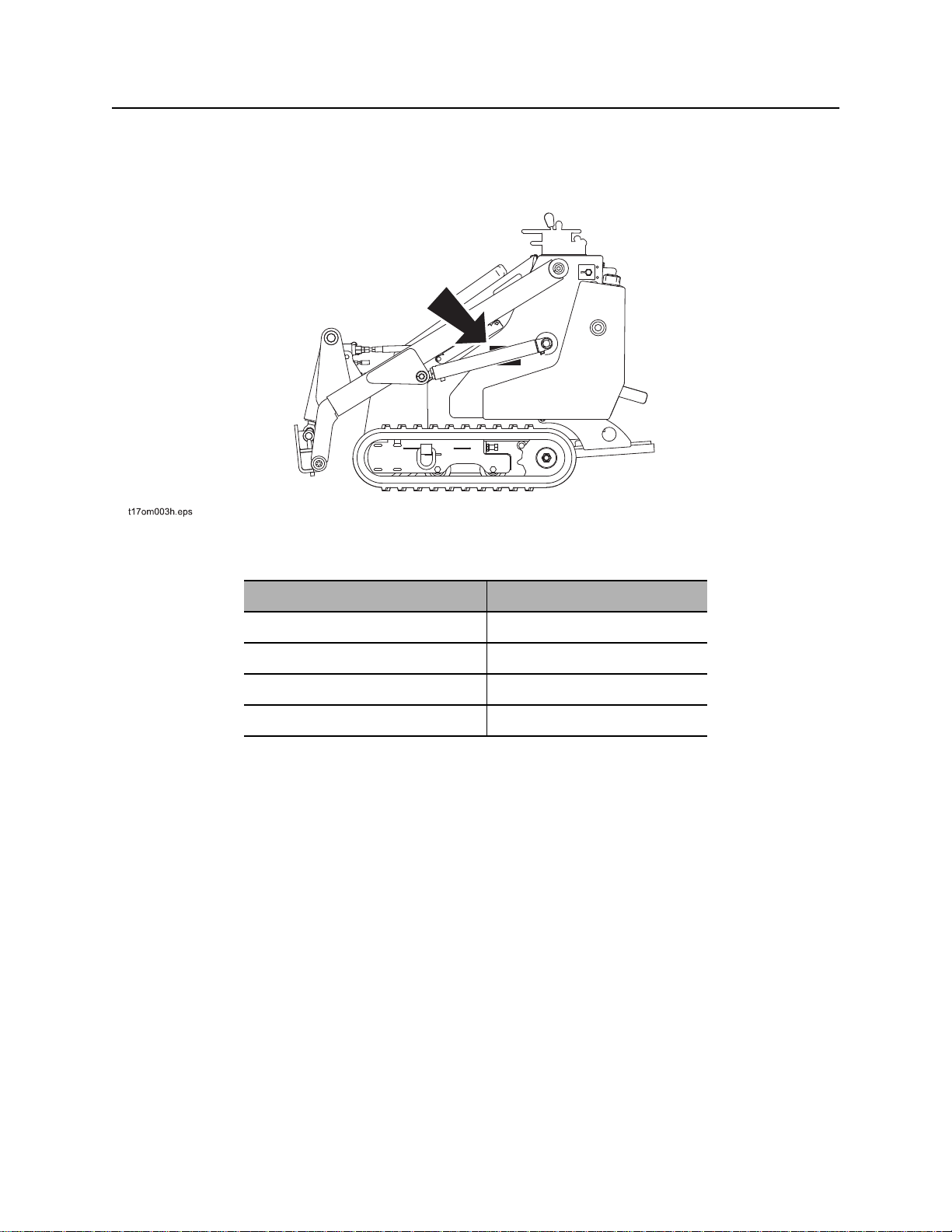
Serial Number Location
Serial Number Location
Record serial numbers and date of purchase in spaces provided. Unit serial number is located as shown.
Item
date of manufacture
date of purchase
unit serial number
engine serial number
CMW
SK350 Operator’s Manual Overview - 3
Intended Use
Intended Use
The SK350 is a platform rubber track mini skid steer unit designed for compact construction work. The
SK350 has a quick attach mount plate which makes it easy for an operator to connect different
attachments. The unit is designed for operation in temperatures typically experienced in earth moving and
construction work environments. Provisions may be required to operate in extreme temperatures. Contact
your Ditch Witch dealer.
The SK350 should be operated, serviced, and repaired only by persons familiar with its particular
characteristics and acquainted with the relevant safety procedures.
Equipment Modification
This equipment was designed and built in accordance with applicable standards and regulations.
Modification of equipment could mean that it will no longer meet regulations and may not function properly
or in accordance with the operating instructions. Modification of equipment should only be made by
competent personnel possessing knowledge of applicable standards, regulations, equipment design
functionality/requirements and any required specialized testing.
Use in any other way is considered contrary to the intended use.
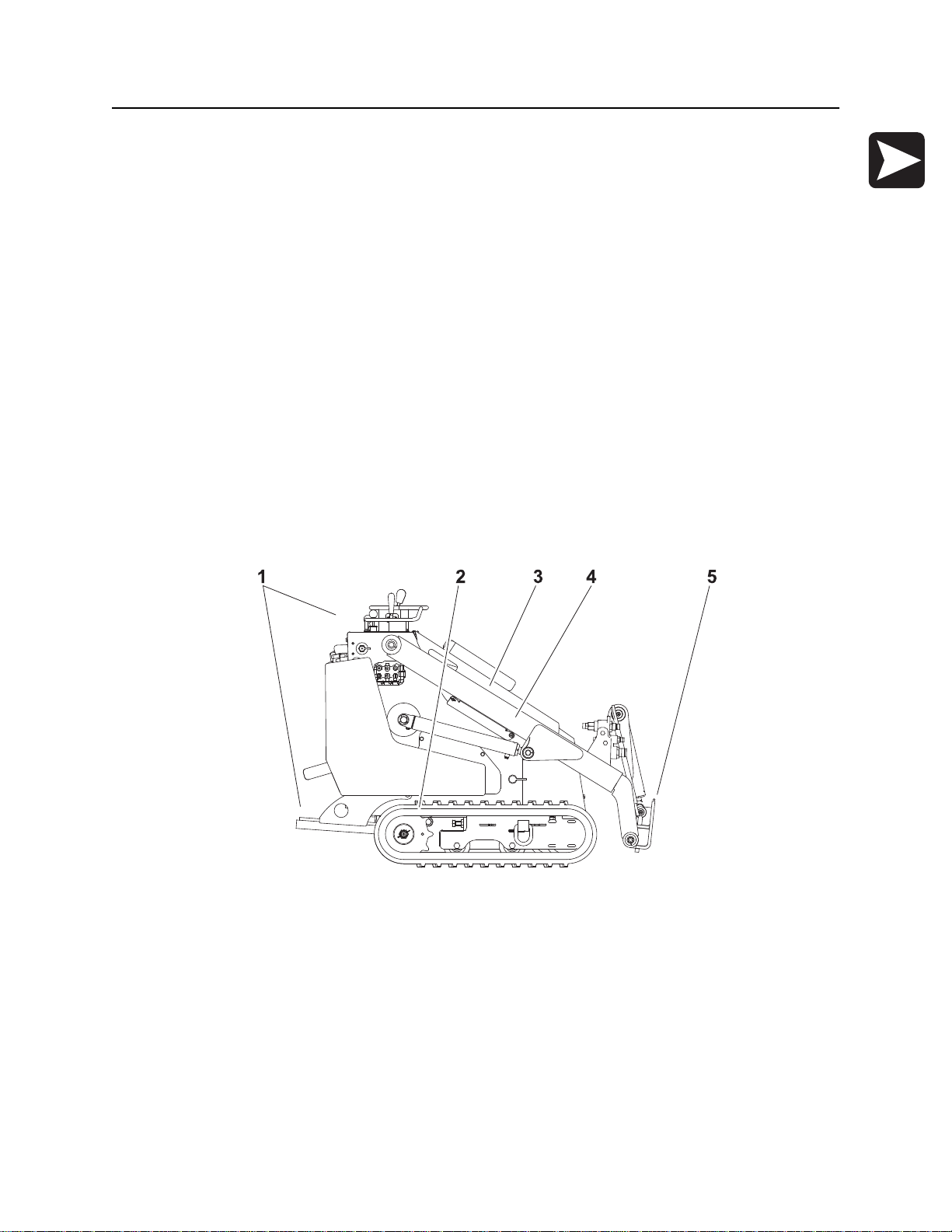
Unit Components
1. Operator station
2. Tracks
3. Engine compartment
4. Lift arms
5. Mount plate
CMW
Overview - 4 SK350 Operator’s Manual
Operator Orientation
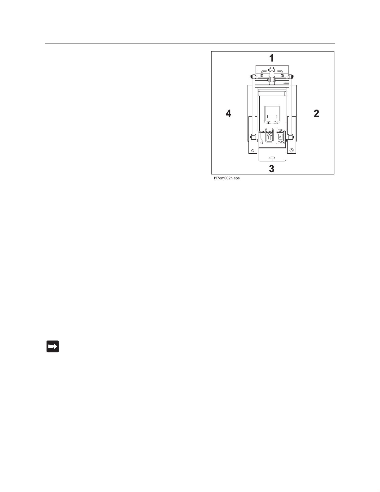
Operator Orientation
1. Front of unit
2. Right side of unit
3. Rear of unit
4. Left side of unit
About This Manual
This manual contains information for the proper use of this machine. Cross references such as “See page
50” will direct you to detailed procedures.
Bulleted Lists
Bulleted lists provide helpful or important information or contain procedures that do not have to be
performed in a specific order.
Numbered Lists
Numbered lists contain illustration callouts or list steps that must be performed in order.
“Continued” Indicators
indicates that a procedure is continued on the next page.
CMW

SK350 Operator’s Manual Foreword - 5
Foreword
This manual is an important part of your equipment. It provides safety information and operation
instructions to help you use and maintain your Ditch Witch equipment.
Read this manual before using your equipment. Keep it with the equipment at all times for future reference.
If you sell your equipment, be sure to give this manual to the new owner.
If you need a replacement copy, contact your Ditch Witch dealer. If you need assistance in locating a
dealer, visit our website at www.ditchwitch.com or write to the following address:
The Charles Machine Works, Inc.
Attn: Marketing Department
PO Box 66
Perry, OK 73077-0066
USA
The descriptions and specifications in this manual are subject to change without notice. The Charles
Machine Works, Inc. reserves the right to improve equipment. Some product improvements may have
taken place after this manual was published. For the latest information on Ditch Witch equipment, see your
Ditch Witch dealer.
Thank you for buying and using Ditch Witch equipment.
CMW

Foreword - 6 SK350 Operator’s Manual
SK350
Operator’s Manual
Issue number 3.1/OM-7/14
Part number 054-137
Copyright 2005, 2006, 2007, 2008, 2011, 2014
by The Charles Machine Works, Inc.
, Ditch Witch, CMW, AutoCrowd, Modularmatic, Jet Trac, Roto Witch, Subsite,
Fluid Miser, Perma-Soil, Power Pipe, Super Witch, Super Witch II, Pierce Airrow, The Underground, and
The Underground Authority Worldwide are registered trademarks of The Charles Machine Works, Inc.
CMW
SK350 Operator’s Manual Contents - 7
Contents
Overview
machine serial number, information about the type of work this machine is designed
to perform, basic machine components, and how to use this manual
Foreword
part number, revision level, and publication date of this manual, and factory contact
information
Safety
machine safety alerts and emergency procedures
Controls
machine controls, gauges, and indicators and how to use them
Prepare
procedures for inspecting and classifying the jobsite, planning the installation path (if
needed), preparing the jobsite for work, and connecting attachments
Drive
procedures for startup, cold start, driving, and shutdown
Transport
procedures for lifting, hauling, and towing
1
5
9
19
23
31
35
Complete the Job
procedures for restoring the jobsite and rinsing and storing equipment
Service
service intervals and instructions for this machine including lubrication, replacement
of wear items, and basic maintenance
Specifications
machine specifications including weights, measurements, power ratings, and fluid
capacities
Support
the warranty policy for this machine, and procedures for obtaining warranty
consideration and training
Service Record
a record of major service performed on the machine
43
45
67
71
75
CMW

Contents - 8 SK300 Operator’s Manual
CMW

SK350 Operator’s Manual Safety - 9
Safety
Chapter Contents
Guidelines . . . . . . . . . . . . . . . . . . . . . . . . . . . . . . . . 10
Safety Alert Classifications . . . . . . . . . . . . . . . . . . 11
Safety Alerts . . . . . . . . . . . . . . . . . . . . . . . . . . . . . . 12
Emergency Procedures . . . . . . . . . . . . . . . . . . . . . 15
• Electric Strike Description . . . . . . . . . . . . . . . . . . . . . . . . . . . . . . . . . . 15
• If an Electric Line is Damaged . . . . . . . . . . . . . . . . . . . . . . . . . . . . . . . 16
• If a Gas Line is Damaged . . . . . . . . . . . . . . . . . . . . . . . . . . . . . . . . . . . 16
• If a Fiber Optic Cable is Damaged . . . . . . . . . . . . . . . . . . . . . . . . . . . . 17
• If Machine Catches on Fire . . . . . . . . . . . . . . . . . . . . . . . . . . . . . . . . . 17
CMW

Safety - 10 SK350 Operator’s Manual
Guidelines
Guidelines
Follow these guidelines before operating any jobsite equipment:
• Complete proper training and read operator’s manual before using equipment.
• Contact your local One-Call (811 in USA) or the One-Call referral number (888-258-0808 in USA and
Canada) to have underground utilities located before digging. Also contact any utilities that do not
participate in the One-Call service.
• Classify jobsite based on its hazards and use correct tools and machinery, safety equipment, and work
methods for jobsite.
• Mark jobsite clearly and keep spectators away.
• Wear personal protective equipment.
• Review jobsite hazards, safety and emergency procedures, and individual responsibilities with all
personnel before work begins. Safety videos are available from your Ditch Witch dealer.
• Replace missing or damaged safety shields and safety signs.
• Use equipment carefully. Stop operation and investigate anything that does not look or feel right.
• Do not operate unit where flammable gas is present.
• Contact your Ditch Witch dealer if you have any question about operation, maintenance, or equipment
use.
CMW

SK350 Operator’s Manual Safety - 11
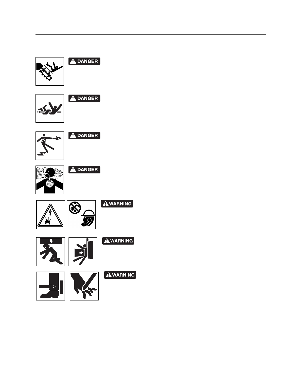
Safety Alert Classifications
Safety Alert Classifications
These classifications and the icons defined on the following pages work together to alert you to situations
which could be harmful to you, jobsite bystanders or your equipment. When you see these words and
icons in the book or on the machine, carefully read and follow all instructions. YOUR SAFETY IS AT
STAKE.
Watch for the three safety alert levels: DANGER, WARNING and CAUTION. Learn what each level
means.
indicates an imminently hazardous situation which, if not avoided, will result in death or
serious injury.
indicates a potentially hazardous situation which, if not avoided, could result in death or
serious injury.
indicates a potentially hazardous situation which, if not avoided, may result in minor or
moderate injury.
Watch for two other words: NOTICE and IMPORTANT.
NOTICE can keep you from doing something that might damage the machine or someone's property. It
can also alert you against unsafe practices.
IMPORTANT can help you do a better job or make your job easier in some way.
CMW
Safety - 12 SK350 Operator’s Manual
Safety Alerts
Safety Alerts
Moving digging teeth will kill you or cut off arm or leg. Stay away.
Turning shaft will kill you or crush arm or leg. Stay away.
Electric shock. Contacting electric lines will cause death or serious injury.
Know location of lines and stay away.
Deadly gases. Lack of oxygen or presence of gas will cause sickness or
death. Provide ventilation.
correct equipment and work methods. Use and maintain proper safety
equipment.
proper procedures and equipment or stay away.
Jobsite hazards could cause death or serious injury. Use
Crushing weight could cause death or serious injury. Use
Moving parts could cut off hand or foot. Stay away.
CMW
SK350 Operator’s Manual Safety - 13
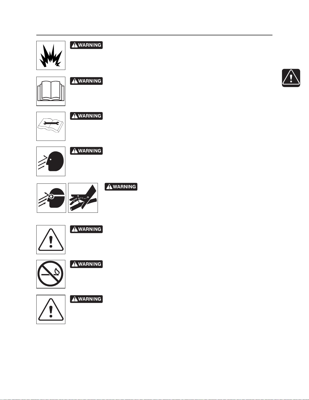
Safety Alerts
Explosion possible. Serious injury or equipment damage could occur.
Follow directions carefully.
Incorrect procedures could result in death, injury, or property damage.
Learn to use equipment correctly.
Improper control function could cause death or serious injury. If control does
not work as described in instructions, stop machine and have it serviced.
Looking into fiber optic cable could result in permanent vision damage. Do
not look into ends of fiber optic or unidentified cable.
Fluid or air pressure could pierce skin and cause injury or
death. Stay away.
Runaway possible. Machine could run over you or others. Learn how to use
all controls. Start and operate only from operator’s position.
Fire or explosion possible. Fumes could ignite and cause burns. No
smoking, no flame, no spark.
Moving traffic - hazardous situation. Death or serious injury could result.
Avoid moving vehicles, wear high visibility clothing, post appropriate warning signs.
CMW
Safety - 14 SK350 Operator’s Manual
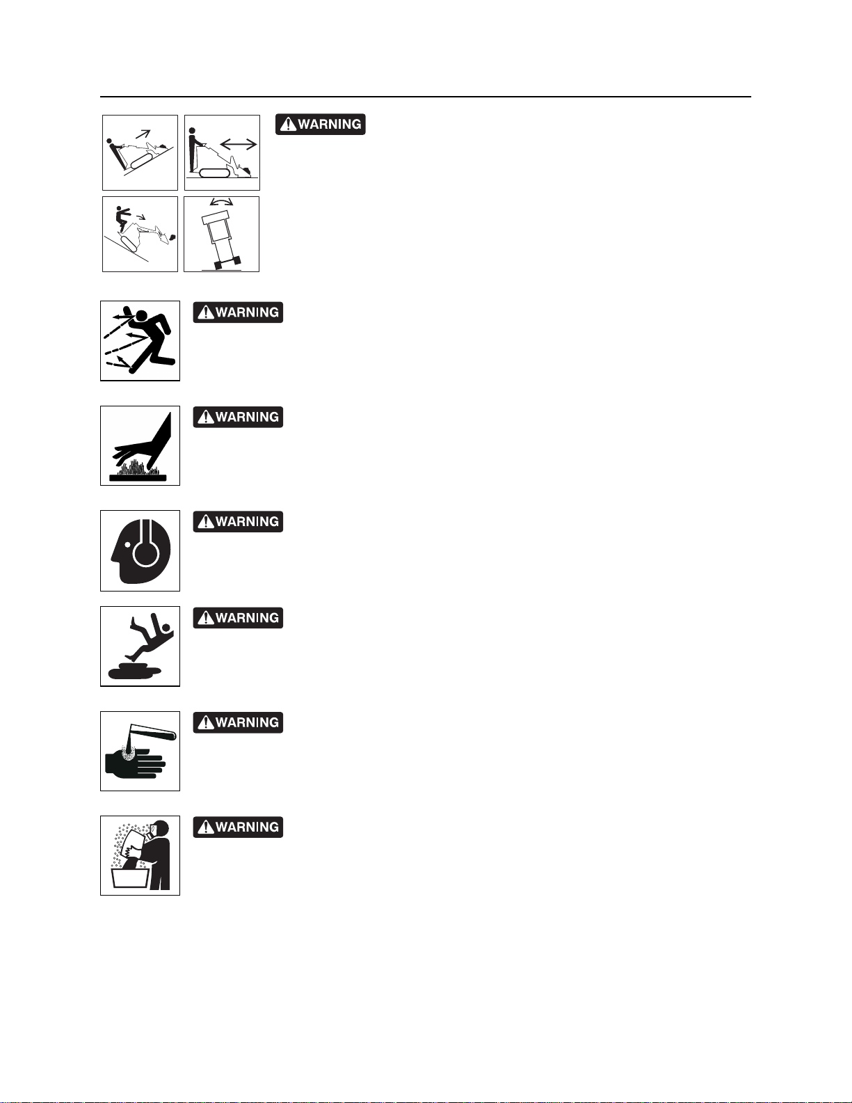
Safety Alerts
Tipover possible. Machine can tip over and crush you.
• Always operate with load end uphill.
• Always carry load low. High load can cause tipping, loss of load or loss of
visibility.
• Never jerk control levers. Use a steady even motion.
• See operator’s manual for tip capacity.
Flying objects may cause injury. Wear hard hat and safety glasses.
Hot parts may cause burns. Do not touch until cool.
Exposure to high noise levels may cause hearing loss. Wear hearing
protection.
Fall possible. Slips or trips may result in injury. Keep area clean.
Battery acid may cause burns. Avoid contact.
Improper handling or use of chemicals may result in illness, injury, or
equipment damage. Follow instructions on labels and in material safety data sheets
(MSDS).
CMW

SK350 Operator’s Manual Safety - 15
Emergency Procedures
Emergency Procedures
Before operating any equipment, review emergency procedures and check that all safety precautions have
been taken.
EMERGENCY SHUTDOWN - Turn ignition switch to STOP.
Electric Strike Description
When working near electric cables, remember the following:
• Electricity follows all paths to ground, not just path of least resistance.
• Pipes, hoses, and cables will conduct electricity back to all equipment.
• Low voltage current can injure or kill. Almost one-third of work-related electrocutions result from
contact with less than 440 volts.
Most electric strikes are not noticeable, but indications of a strike include:
• power outage
• smoke
• explosion
• popping noises
• arcing electricity
If any of these occur, assume an electric strike has occurred.
CMW

Safety - 16 SK350 Operator’s Manual
Emergency Procedures
If an Electric Line is Damaged
If you suspect an electric line has been damaged and you are on tractor, DO NOT MOVE. Remain on
tractor and take the following actions. The order and degree of action will depend upon the situation.
• Warn people nearby that an electric strike has occurred. Instruct them to leave the area and contact
utility.
• Raise attachments and drive from immediate area.
• Contact utility company to shut off power.
• Do not return to jobsite or allow anyone into area until given permission by utility company.
If you suspect an electric line has been damaged and you are off tractor, DO NOT TOUCH TRACTOR.
Take the following actions. The order and degree of action will depend upon the situation.
• LEAVE AREA. The ground surface may be electrified, so take small steps with feet close together to
reduce the hazard of being shocked from one foot to the other. For more information, contact your
Ditch Witch dealer.
• Contact utility company to shut off power.
• Do not return to jobsite or allow anyone into area until given permission by utility company.
If a Gas Line is Damaged
If you suspect a gas line has been damaged, take the following actions. The order and degree of action will
depend on the situation.
• Immediately shut off engine(s), if this can be done safely and quickly.
• Remove any ignition source(s), if this can be done safely and quickly.
• Warn others that a gas line has been cut and that they should leave the area.
• Leave jobsite as quickly as possible.
• Immediately call your local emergency phone number and utility company.
• If jobsite is along street, stop traffic from driving near jobsite.
• Do not return to jobsite until given permission by emergency personnel and utility company.
CMW

SK350 Operator’s Manual Safety - 17
Emergency Procedures
If a Fiber Optic Cable is Damaged
Do not look into cut ends of fiber optic or unidentified cable. Vision damage can occur.
If Machine Catches on Fire
Perform emergency shutdown procedure and then take the following actions. The order and degree of
action will depend on the situation.
• Immediately move battery disconnect switch (if equipped) to disconnect position.
• If fire is small and fire extinguisher is available, attempt to extinguish fire.
• If fire cannot be extinguished, leave area as quickly as possible and contact emergency personnel.
CMW

Safety - 18 SK350 Operator’s Manual
Emergency Procedures
CMW
SK350 Operator’s Manual Controls - 19
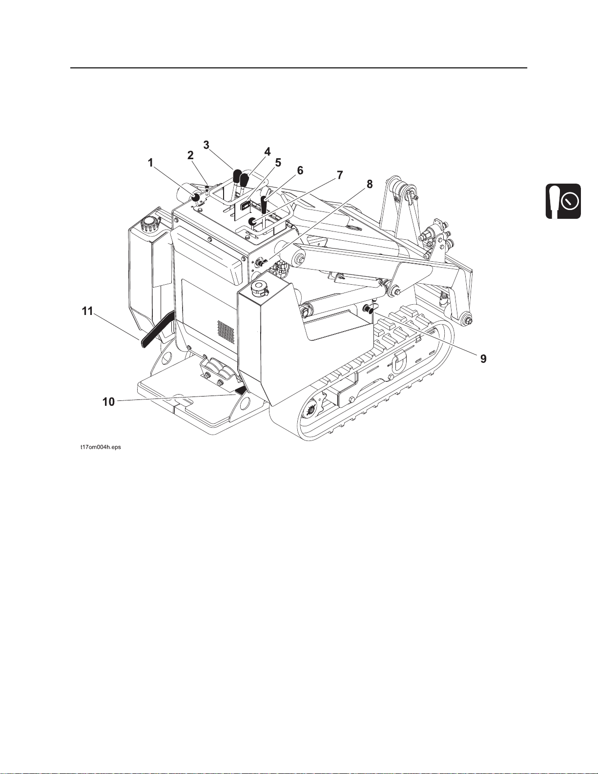
Controls
1. Throttle
2. Choke
3. Left track drive control
4. Right track drive control
5. Tachometer/Hourmeter
6. Lift arm control
7. Attachment drive control
8. Ignition switch
9. Jumper terminal
10. Attachment drive foot control
11. Parking brake lever
CMW
Controls - 20 SK350 Operator’s Manual
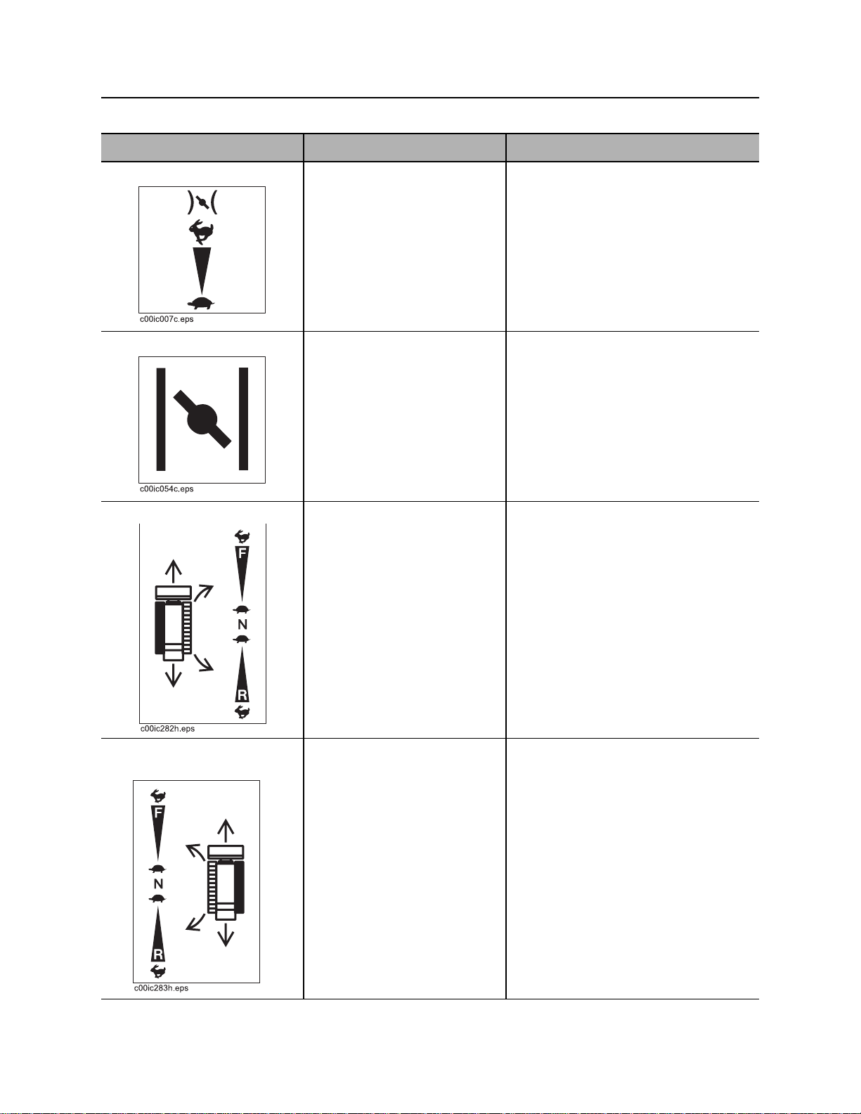
Item Description Notes
1. Throttle To increase engine speed,
push.
To decrease engine speed,
pull.
2. Choke To help start cold engine, pull
knob.
When engine has warmed,
push in completely.
3. Left track drive control To move forward, push.
To move backward, pull.
To go faster in either
direction, move control farther
from neutral.
To stop, move to neutral.
Increasing engine speed also
increases attachment speed.
NOTICE: Always stop engine at full
throttle.
To turn right, move left control forward
and right control back.
To turn left, move right control forward
and left control back.
To counter-rotate in either direction,
move controls fully to ends in the
directions indicated above.
4. Right track drive
control
CMW
To move forward, push.
To move backward, pull.
To go faster in either
direction, move control farther
from neutral.
To stop, move to neutral.
To turn right, move left control forward
and right control back.
To turn left, move right control forward
and left control back.
To counter-rotate in either direction,
move controls fully to ends in the
directions indicated above.
SK350 Operator’s Manual Controls - 21
Item Description Notes
5. Tachometer/Hourmeter Displays engine speed and
operating time.
6. Lift arm control To move lift arms down, push.
To float, push forward to end.
To move lift arms up, pull.
To curl attachment up, move
to left.
To curl attachment down,
move to right.
7. Attachment drive
control
To engage attachment drive
in reverse, lift lever release
then push to left.
Use hourmeter to schedule service.
Flashes “Lube & Chg Oil” alerts for 2
hours at 25-hour intervals.
IMPORTANT:
• Do not exceed rated operating
capacity when lifting loads. See
page 68.
• In float, weight of attachment
allows attachment to follow
ground contour.
IMPORTANT: See attachment drive
foot control on page 22.
To engage attachment drive
in forward, lift lever release,
then push right.
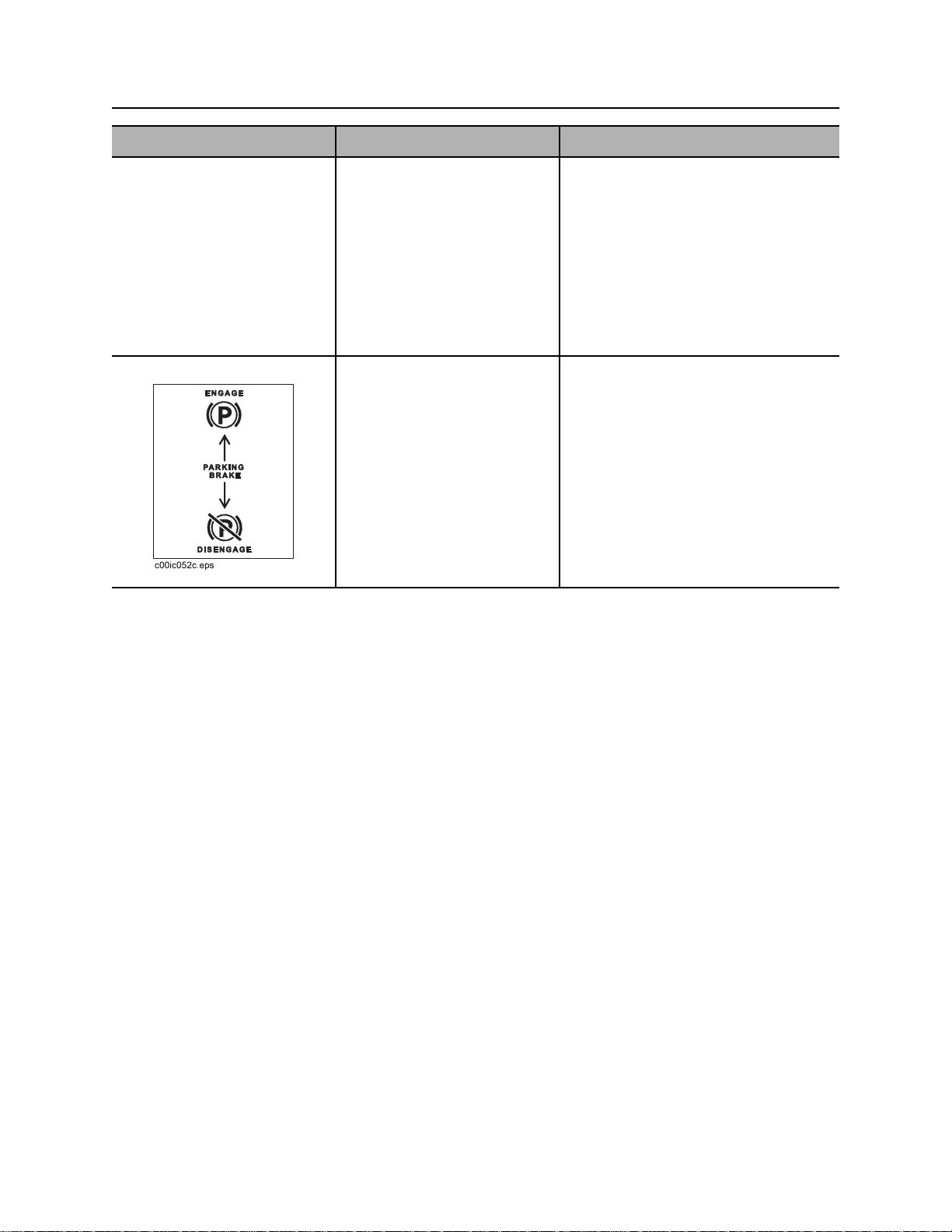
8. Ignition switch To start engine, insert key and
turn clockwise.
To stop engine, turn key
counterclockwise.
9. Jumper terminal Use to start engine when
battery is dead.
IMPORTANT: If engine does not start
or stalls, turn key to STOP and then
restart.
NOTICE: Always stop engine at full
throttle.
IMPORTANT: See “Park service
vehicle close to disabled equipment
but do not allow vehicles to touch.” on
page 65.
CMW
Controls - 22 SK350 Operator’s Manual
Item Description Notes
10. Attachment drive foot
control
11. Parking brake lever To disengage, push down.
Attachment drive control
handle must be engaged
before using the foot pedal.
To hold attachment drive in
forward position, press pedal.
To return attachment drive
control to neutral, release
pedal.
To engage, push down and
outward, then pull up.
IMPORTANT: Use this control to hold
attachment control in the on position
when hands are busy operating lift
arm controls or track drive.
IMPORTANT:
• Lever locks into position under
tab.
• Lever must be moved outward to
clear tab.
CMW

SK350 Operator’s Manual Prepare - 23
Prepare
Chapter Contents
Gather Information . . . . . . . . . . . . . . . . . . . . . . . . . 24
• All Jobs . . . . . . . . . . . . . . . . . . . . . . . . . . . . . . . . . . . . . . . . . . . . . . . . . 24
• Ground-Penetrating Jobs . . . . . . . . . . . . . . . . . . . . . . . . . . . . . . . . . . . 24
• Above-Ground Jobs . . . . . . . . . . . . . . . . . . . . . . . . . . . . . . . . . . . . . . . 24
Inspect Site . . . . . . . . . . . . . . . . . . . . . . . . . . . . . . . 25
• Identify Hazards . . . . . . . . . . . . . . . . . . . . . . . . . . . . . . . . . . . . . . . . . . 25
Classify Jobsite . . . . . . . . . . . . . . . . . . . . . . . . . . . 26
• Inspect Jobsite . . . . . . . . . . . . . . . . . . . . . . . . . . . . . . . . . . . . . . . . . . . 26
• Select a Classification . . . . . . . . . . . . . . . . . . . . . . . . . . . . . . . . . . . . . 26
• Apply Precautions . . . . . . . . . . . . . . . . . . . . . . . . . . . . . . . . . . . . . . . . 27
Check Supplies and Prepare Equipment . . . . . . . 28
• Supplies . . . . . . . . . . . . . . . . . . . . . . . . . . . . . . . . . . . . . . . . . . . . . . . . 28
• Fluid Levels . . . . . . . . . . . . . . . . . . . . . . . . . . . . . . . . . . . . . . . . . . . . . 28
• Condition and Function . . . . . . . . . . . . . . . . . . . . . . . . . . . . . . . . . . . . 28
• Accessories . . . . . . . . . . . . . . . . . . . . . . . . . . . . . . . . . . . . . . . . . . . . . 28
Connect Attachment . . . . . . . . . . . . . . . . . . . . . . . 29
CMW

Prepare - 24 SK350 Operator’s Manual
Gather Information
Gather Information
A successful job begins before you start working. The first step in planning is reviewing information already
available about the job and jobsite.
All Jobs
Review Job Plan
Review blueprints or other plans. Check for information about existing or planned structures, elevations, or
proposed work that may be taking place at the same time.
Arrange for Traffic Control
If working near a road or other traffic area, contact local authorities about safety procedures and
regulations.
Plan for Emergency Services
Have the telephone numbers for local emergency and medical facilities on hand. Check that you will have
access to a telephone.
Ground-Penetrating Jobs
Notify One-Call Services
Call area One-Call or similar services and have existing lines located and marked. Call any utilities in your
area that do not subscribe to One-Call.
Above-Ground Jobs
Locate Overhead Lines
Note location and height of all overhead lines in jobsite and ensure that fully lifted attachment and/or load
will not touch lines.
CMW

SK350 Operator’s Manual Prepare - 25
Inspect Site
Inspect Site
Inspect jobsite before transporting equipment. Check for the following:
• changes in elevation such as hills or other open trenches
• obstacles such as buildings, railroad crossings, or streams
• signs of utilities (See “Inspect Jobsite” on page 26.)
• traffic
• access
• soil type and condition
Identify Hazards
Identify safety hazards and classify jobsite if attachment will penetrate ground. See “Classify Jobsite” on
page 26.
Jobsite hazards could cause death or serious injury. Use
correct equipment and work methods. Use and maintain proper safety
equipment.
NOTICE:
• Wear personal protective equipment including hard hat, safety eye wear, and hearing protection.
• Do not wear jewelry or loose clothing.
• Notify One-Call and companies which do not subscribe to One-Call.
• Comply with all utility notification regulations before digging or drilling.
• Verify location of previously marked underground hazards.
• Mark jobsite clearly and keep spectators away.
Remember, jobsite is classified by hazards in place -- not by line being installed.
CMW

Prepare - 26 SK350 Operator’s Manual
Classify Jobsite
Classify Jobsite
Inspect Jobsite
• Inspect jobsite and perimeter for evidence of underground hazards, such as:
– “buried utility” notices
– utility facilities without overhead lines
– gas or water meters
– junction boxes
– drop boxes
– light poles
– manhole covers
– sunken ground
• Follow U.S. Department of Labor regulations on excavating and trenching (Part 1926, Subpart P) and
other similar regulations.
• Contact One-Call (888-258-0808) and any utility companies which do not subscribe to One-Call.
• Have an experienced locating equipment operator sweep area within 20’ (6 m) to each side of work
path. Verify previously marked line and cable locations.
• Mark location of all buried utilities and obstructions.
• Classify jobsite.
Select a Classification
Jobsites are classified according to underground hazards present.
If working . . . then classify jobsite as . . .
within 10’ (3 m) of a buried electric line electric
within 10’ (3 m) of a natural gas line natural gas
in sand, granite, or concrete which is capable of producing
crystalline silica (quartz) dust
within 10’ (3 m) of any other hazard other
NOTICE: If you have any doubt about jobsite classification, or if jobsite might contain unmarked
hazards, take steps outlined previously to identify hazards and classify jobsite before working.
crystalline silica (quartz) dust
CMW

SK350 Operator’s Manual Prepare - 27
Classify Jobsite
Apply Precautions
Once classified, precautions appropriate for jobsite must be taken.
Electric Jobsite Precautions
Use one or both of these methods.
• Expose line by careful hand digging or soft excavation.
• Have service shut down while work is in progress. Have electric company test lines before returning
them to service.
Natural Gas Jobsite Precautions
In addition to positioning equipment upwind from gas lines, use one or both of these methods.
• Expose lines by careful hand digging or soft excavation.
• Have gas shut off while work is in progress. Have gas company test lines before returning them to
service.
Crystalline Silica (Quartz) Dust Precautions
Follow OSHA or other guidelines for exposure to crystalline silica when trenching, sawing or drilling
through material that might produce dust containing crystalline silica (quartz).
Other Jobsite Precautions
You may need to use different methods to safely avoid other underground hazards. Talk with those
knowledgeable about hazards present at each site to determine which precautions should be taken or if
job should be attempted.
CMW

Prepare - 28 SK350 Operator’s Manual
Check Supplies and Prepare Equipment
Check Supplies and Prepare Equipment
Supplies
• fuel
• keys
• lubricants
• personal protective equipment, such as hard hat and safety glasses
Fluid Levels
• fuel
• hydraulic fluid
• battery charge
• engine oil
Condition and Function
• digging chain and teeth
• filters (air, oil, hydraulic)
• tracks
• pumps and motors
• hoses and valves
• signs, guards, and shields
Accessories
Fire Extinguisher
If required, mount a fire extinguisher near the power unit but away from possible points of ignition. The fire
extinguisher should always be classified for both oil and electric fires. It should meet legal and regulatory
requirements.
CMW

SK350 Operator’s Manual Prepare - 29
Connect Attachment
Connect Attachment
IMPORTANT: Use only Ditch Witch-approved attachments. Attachments can change the stability and
operating characteristics of the unit.
Attachment
IMPORTANT: Before connecting attachment to unit, ensure that mount and receiver plates are free of
dirt and debris.
1. Position attachment on level surface with enough
space behind it to accommodate unit.
2. Ensure that lock pin handles (shown) on mount
plate are turned away from center of attachment.
3. Start engine.
4. Tilt mount plate (2) forward.
5. Position mount plate in the upper lip of the receiver
plate (1) on attachment.
6. Raise lift arms while tilting back mount plate.
IMPORTANT: Attachment should be raised
enough to clear the ground. Mount plate
should be tilted back fully.
7. Ensure that all controls are in neutral position.
8. Apply parking brake.
9. Turn ignition switch off and remove key.
10. Rotate lock pin handles toward center of mount
plate to secure attachment to lift plate.
NOTICE: To ensure proper connection, verify
that bottoms of lock pins are visible under
attachment receiver plate (shown).
t05om022c.eps
12
t05om026c.eps
t05om027c.eps
CMW

Prepare - 30 SK350 Operator’s Manual
Connect Attachment
Hydraulic Hoses
If attachment requires hydraulic power for operation, connect hydraulic hoses.
Fluid or air pressure could pierce skin and cause injury or
death. Stay away.
NOTICE:
• Escaping pressurized fluid can cause injury or pierce skin and poison.
• Before disconnecting a hydraulic line, turn engine off and operate all controls to relieve pressure.
Lower, block, or support any raised component with a hoist. Cover connection with heavy cloth and
loosen connector nut slightly to relieve residual pressure. Catch all fluid in a container.
• Before using system, check that all connections are tight and all lines are undamaged.
• Fluid leaks can be hard to detect. Use a piece of cardboard or wood, rather than hands, to search
for leaks.
• Wear protective clothing, including gloves and eye protection.
• If you are injured, seek immediate medical attention from a doctor familiar with this type of injury.
Hot parts may cause burns. Do not touch until cool.
NOTICE: Hydraulic couplers, hoses and fluid may be hot. Wear gloves when connecting and
disconnecting hydraulic hoses and wait until unit has cooled before touching hydraulic components.
1. Cycle attachment drive control to relieve residual
pressure at hydraulic couplers.
2. Ensure that all controls are in neutral position.
3. Remove dirt and debris from hydraulic couplers.
4. Connect male coupler on attachment to female
coupler (3) on unit.
5. Connect female coupler on attachment to male
coupler (1) on unit.
6. Connect female coupler on case drain hose to case
drain coupler (2) on unit, if attachment requires it.
7. Ensure that connections are secure by pulling on
hoses.
CMW

SK350 Operator’s Manual Drive - 31
Drive
Chapter Contents
Start Engine. . . . . . . . . . . . . . . . . . . . . . . . . . . . . . . 32
Drive. . . . . . . . . . . . . . . . . . . . . . . . . . . . . . . . . . . . . 32
Shut Down . . . . . . . . . . . . . . . . . . . . . . . . . . . . . . . . 34
CMW

Drive - 32 SK350 Operator’s Manual
Start Engine
Start Engine
1. Ensure all controls are in neutral.
2. If necessary, choke cold engine.
3. Move throttle to half open.
4. Turn ignition switch to start position and release when engine starts.
NOTICE: If jump starting is required, see “Park service vehicle close to disabled equipment but
do not allow vehicles to touch.” on page 65.
5. Push in choke after engine is warm.
EMERGENCY SHUTDOWN: Turn ignition switch to STOP.
Drive
General Operation
1. Disengage parking brake.
2. Pull lift arm control to raise mount plate (and attachment) off ground.
3. Move both track drive controls to forward or reverse. See page 20.
IMPORTANT: If needed for attachment operation, push attachment drive foot control to hold
attachment control in the forward position while operating track drive and lift arm controls.
4. Adjust throttle as needed.
CMW

SK350 Operator’s Manual Drive - 33
Drive
Safe Slope Operation
Tipover possible. Machine can tip over and crush you.
• Always operate with heavy end uphill.
• Always carry load low. High load can cause tipping, loss of load or loss of
visibility.
• Drive cautiously at all times.
• Never jerk control levers. Use a steady even motion.
• Do not park unit on slope without lowering attachment to the ground,
returning all controls to neutral position, shutting down unit, and applying
parking brake.
• See “Tipping capacity” on page 67.
Operating safely on a slope depends upon many factors including:
• Distribution of machine weight, including front loading and absence of load
• Height of load
• Even or rough ground conditions
• Potential for ground giving way causing unplanned tilt forward, reverse or sideways
• Nearness of ditches, ruts, stumps or other obstructions and sudden changes in slope
• Speed
• Turning
• Braking performance
• Operator skill
These varying factors make it impractical to specify a maximum safe operating angle in this manual. It is
therefore important for the operator to be aware of these conditions and adjust operation accordingly.
Maximum engine angle and braking performance are two absolute limits which must never be exceeded.
These maximums are stated below since they are design limits. These design limits usually exceed the
operating limits and must never be used alone to establish safe operating angle for variable conditions.
Maximum engine lubrication angle – 20°
Maximum service brake retarding force – equal to traction of both tracks.
Maximum secondary brake retarding force – equal to traction of one track.
Maximum park brake holding force – equal to traction of both tracks.
CMW

Drive - 34 SK350 Operator’s Manual
Shut Down
Shut Down
1. Lower lift arms to ground.
2. Move all controls to neutral position.
3. Apply parking brake.
4. Run engine at full throttle for three minutes to cool.
5. Turn ignition switch to STOP.
6. Remove key.
NOTICE:
• Unit should not be parked on a slope unless parking brake is engaged.
• Move all controls to neutral position when stopped.
CMW

SK350 Operator’s Manual Transport - 35
Transport
Chapter Contents
Lift . . . . . . . . . . . . . . . . . . . . . . . . . . . . . . . . . . . . . . 36
• Points . . . . . . . . . . . . . . . . . . . . . . . . . . . . . . . . . . . . . . . . . . . . . . . . . . 36
• Procedure . . . . . . . . . . . . . . . . . . . . . . . . . . . . . . . . . . . . . . . . . . . . . . . 36
Haul . . . . . . . . . . . . . . . . . . . . . . . . . . . . . . . . . . . . . 37
• Inspect Trailer . . . . . . . . . . . . . . . . . . . . . . . . . . . . . . . . . . . . . . . . . . . 37
• Hitch Trailer . . . . . . . . . . . . . . . . . . . . . . . . . . . . . . . . . . . . . . . . . . . . . 37
• Load . . . . . . . . . . . . . . . . . . . . . . . . . . . . . . . . . . . . . . . . . . . . . . . . . . . 38
• Tie Down . . . . . . . . . . . . . . . . . . . . . . . . . . . . . . . . . . . . . . . . . . . . . . . 39
• Unload . . . . . . . . . . . . . . . . . . . . . . . . . . . . . . . . . . . . . . . . . . . . . . . . . 40
• Unhitch Trailer . . . . . . . . . . . . . . . . . . . . . . . . . . . . . . . . . . . . . . . . . . . 40
Tow . . . . . . . . . . . . . . . . . . . . . . . . . . . . . . . . . . . . . 41
CMW

Transport - 36 SK350 Operator’s Manual
Lift
Lift
Crushing weight. If load falls or moves it could kill or crush you. Use
proper procedures and equipment or stay away.
Points
Lifting points are identified by lifting decals. Lifting at other points is unsafe
and can damage machinery.
Procedure
Use a hoist capable of supporting the equipment's size
and weight. See “Specifications” on page 67 or
measure and weigh equipment before lifting. Use four
lift points. Attach securely to cross members.
CMW

SK350 Operator’s Manual Transport - 37
Haul
Haul
IMPORTANT: For complete information, see the trailer manufacturer’s manual.
Inspect Trailer
• Check hitch for wear and cracks. Lubricate if needed.
• Check battery for 12V charge, if installed.
• Inspect lights for cleanliness and correct operation. Inspect reflectors and replace if needed.
• Check tire pressure. Check lug nut torque with a torque wrench. Adjust if needed.
• If equipped, ensure trailer brakes are adjusted to come on in synchronization with tow vehicle brakes.
• Check ramps and trailer bed for cracks.
Hitch Trailer
1. Back tow vehicle to trailer.
2. Put manual transmission into first or reverse gear or automatic transmission into park. Turn off ignition.
Set parking brake.
3. Connect trailer drawbar, lunette or coupler to tow vehicle hitch and lock in place with lock pin. If
needed, adjust drawbar, lunette or coupler height to level load.
4. Connect safety chains to tow vehicle.
IMPORTANT: Do not connect safety chains to pintle hook or hitch ball.
5. If equipped, connect breakaway switch cable to tow vehicle.
IMPORTANT: Do not connect breakaway switch cable to pintle hook or hitch ball.
6. If equipped, plug trailer electrical connector into tow vehicle connector.
7. If equipped, use jack crank to raise jack base and stow.
8. Remove wheel blocks.
CMW

Transport - 38 SK350 Operator’s Manual
Haul
Load
Crushing weight. If load falls or moves it could kill or crush you. Use
proper procedures and equipment or stay away.
NOTICE:
• Load and unload trailer on level ground.
• Attach trailer to vehicle before loading or unloading.
• Ten to fifteen percent of total vehicle weight (equipment plus trailer) must be on tongue to help
prevent trailer sway.
• Incorrect loading can cause trailer sway.
1. Disengage parking brake.
2. Start engine.
3. Adjust throttle to low speed.
4. Pull lift arm control to raise mount plate (and attachment) clear of trailer, but keep it low.
5. Move unit to rear of trailer and align with ramps.
6. Move both track drive controls forward and slowly move unit onto trailer until tiedown position is
reached.
NOTICE:
• If loading onto tilt-bed trailer, be prepared for trailer to tilt.
• Move all controls to neutral position when stopped.
7. Push lift arm control to lower mount plate (and attachment) to trailer bed.
8. Apply parking brake.
9. Ensure that all controls are in neutral position.
10. Turn ignition switch to STOP.
11. Tie down unit.
CMW

SK350 Operator’s Manual Transport - 39
Haul
Tie Down
Points
Tiedown points are identified by tiedown decals. Securing to truck or trailer
at other points is unsafe and can damage machinery.
Procedure
Loop tiedowns around unit at tiedown points. Make sure tiedowns are tight before transporting.
CMW

Transport - 40 SK350 Operator’s Manual
Haul
Unload
Crushing weight. If load falls or moves it could kill or crush you. Use
proper procedures and equipment or stay away.
NOTICE:
• Load and unload trailer on level ground.
• Attach trailer to vehicle before loading or unloading.
1. Prepare trailer and ramps for unloading.
2. Remove tiedowns.
3. Disengage parking brake.
4. Start engine.
5. Pull lift arm control to raise mount plate (and attachment) off ground, but keep it low.
6. Adjust throttle to low speed and slowly back unit down trailer or ramps.
NOTICE: If unloading from tilt-bed trailer, be prepared for trailer to tilt.
Unhitch Trailer
1. Stop tow vehicle and trailer on level ground.
2. Put manual transmission into first or reverse gear or automatic transmission into park. Turn off ignition.
Set parking brake.
3. Block trailer wheels.
4. Reverse “Hitch Trailer” steps on page 37 to unhitch trailer from tow vehicle.
CMW

SK350 Operator’s Manual Transport - 41
Tow
Tow
Under normal conditions, unit should not be towed. If unit breaks down and towing is necessary:
• attach chains to tow points facing towing vehicle
• tow for short distances at less than 1 mph (1.6 km/h)
• do not tow for more than 100’ (30 m)
• use no more than 1,300 lb (5800 N) of towing force
• disengage parking brake and open tow valves
Prepare Unit for Towing
1. Disengage parking brake, shown.
2. Ensure that all controls are in neutral.
CMW

Transport - 42 SK350 Operator’s Manual
Tow
3. Locate bypass valves on top of each of the upper
pumps. Turn each valve two turns counterclockwise
to open.
4. After towing, turn each valve two turns clockwise to
close.
NOTICE: Bypass valves on BOTH pumps
must be opened for towing.
CMW

SK350 Operator’s Manual Complete the Job - 43
Complete the Job
Chapter Contents
Rinse Equipment . . . . . . . . . . . . . . . . . . . . . . . . . . 44
Disconnect Attachment . . . . . . . . . . . . . . . . . . . . . 44
Stow Tools . . . . . . . . . . . . . . . . . . . . . . . . . . . . . . . 44
CMW

Complete the Job - 44 SK350 Operator’s Manual
Rinse Equipment
Rinse Equipment
1. Spray water onto equipment to remove dirt and mud, especially at undercarriage.
NOTICE: Do not spray water onto operator’s console. Electrical components could be damaged.
Wipe down instead.
2. Open hood and remove debris from inside of unit.
3. Remove mud from track sprockets.
Disconnect Attachment
1. Lower attachment to the ground.
2. Ensure that all controls are in neutral.
3. Turn off engine.
4. Apply parking brake.
5. Disengage lock pins by turning handles away from center of attachment.
6. Cycle attachment drive control and disconnect hydraulic hoses, if used.
7. Disengage parking brake.
8. Start engine.
9. Tilt mount plate forward and back unit away from attachment.
Stow Tools
Make sure all tools and accessories are loaded and properly secured on trailer.
CMW

SK350 Operator’s Manual Service - 45
Service
Chapter Contents
Service Precautions . . . . . . . . . . . . . . . . . . . . . . . . 46
Overview . . . . . . . . . . . . . . . . . . . . . . . . . . . . . . . . . 48
Recommended Lubricants/Service Key . . . . . . . 49
Oil Temperature Chart . . . . . . . . . . . . . . . . . . . . . . 50
10 Hour . . . . . . . . . . . . . . . . . . . . . . . . . . . . . . . . . . 51
50 Hour . . . . . . . . . . . . . . . . . . . . . . . . . . . . . . . . . . 54
100 Hour . . . . . . . . . . . . . . . . . . . . . . . . . . . . . . . . . 58
200 Hour . . . . . . . . . . . . . . . . . . . . . . . . . . . . . . . . . 59
250 Hour . . . . . . . . . . . . . . . . . . . . . . . . . . . . . . . . . 60
500 Hour . . . . . . . . . . . . . . . . . . . . . . . . . . . . . . . . . 61
As Needed . . . . . . . . . . . . . . . . . . . . . . . . . . . . . . . . 62
CMW

Service - 46 SK350 Operator’s Manual
Service Precautions
Service Precautions
Incorrect procedures could result in death, injury, or property damage.
Learn to use equipment correctly.
NOTICES:
• Unless otherwise instructed, all service should be performed with engine off.
• Stop engine and apply parking brake before opening hood for inspection or service.
• Allow engine to cool before performing any service.
• Refer to engine manufacturer’s manual for engine maintenance instructions.
• Before servicing equipment, lower unstowed attachments to ground.
Cleaning Precaution
NOTICE: When cleaning equipment, do not spray electrical components with water.
Jump Starting Precaution
Explosion possible. Serious injury or equipment damage could occur.
Follow directions carefully.
NOTICE:
• Sparks can cause battery to explode.
• Electronic components can be easily damaged.
• Jump starting is not recommended except in extreme circumstances. Follow procedures on
page 64 if jump starting is necessary.
• Improper jump starting could cause damage to the Honda engine voltage regulator rectifier. To
jump start, stop the engine of the service vehicle before connecting jumper cables.
CMW

SK350 Operator’s Manual Service - 47
Service Precautions
Working Under Raised Lift Arms
Crushing weight could cause death or serious injury. Use
proper procedures and equipment or stay away.
NOTICE: Support both lift arms before working under raised lift arms.
Use safety supports as indicated when working under raised lift arms.
Welding Precaution
Explosion possible. Serious injury or equipment damage could occur.
Follow directions carefully.
NOTICE:
• Disconnect battery to prevent damage to battery. Do not turn off battery disconnect switch
with engine running, or alternator and other electronic devices may be damaged.
• Connect welder ground clamp close to welding point and make sure no electronic
components are in the ground path.
• Always disconnect the Engine Control Unit ground connection from the frame, harness
connections to the ECU, and other electronic components prior to welding on machine or
attachments.
CMW

Service - 48 SK350 Operator’s Manual
Overview
Overview
CMW

SK350 Operator’s Manual Service - 49
Recommended Lubricants/Service Key
Recommended Lubricants/Service Key
Item Description
GEO Gasoline engine oil meeting or exceeding SG, SH, or SJ per the API service
classifications and SAE viscosity recommended by engine manufacturer (SAE
10W30)
THF Tractor hydraulic fluid, similar to Phillips 66 HG, Mobilfluid 423, Chevron Tractor
Hydraulic Fluid, Texaco TDH Oil, or equivalent
Check level of fluid or lubricant
Check condition
Filter
Change, replace, adjust, service or test
Proper lubrication and maintenance protects Ditch Witch equipment from damage and failure. Service
intervals listed are for minimum requirements. In extreme conditions, service machine more frequently.
Use only recommended lubricants. Fill to capacities listed in “Fluid Capacities” on page 69.
NOTICE:
• Use only genuine Ditch Witch parts, filters, and approved lubricants to maintain warranty.
• Use the “Service Record” on page 75 to record all required service to your machine.
CMW

Service - 50 SK350 Operator’s Manual
Engine Oil Temperature Chart
Engine Oil Temperature Chart
Temperature range anticipated before next oil change
For more information on engine lubrication and maintenance, see your engine manual.
CMW

SK350 Operator’s Manual Service - 51
10 Hour
10 Hour
Location Task Notes
Traction Unit Check engine oil level GEO (SAE 10 W 30)
Check hydraulic fluid level THF
Check track tension
Check hydraulic hoses
Check Engine Oil Level
Check engine oil level at dipstick opening (shown) every 10 hours. Oil level should be at top of marking. If
low, add 10W30. Check with unit on level surface and at least 15 minutes after stopping engine.
IMPORTANT: Use oil specified in “Engine Oil Temperature Chart” on page 50.
CMW

Service - 52 SK350 Operator’s Manual
10 Hour
Check Hydraulic Fluid Level
Check hydraulic fluid level every 10 hours. Maintain fluid level at halfway point on sight glass (1), when
engine is off and fluid is cool. If low, add THF at fill (2).
Check Track Tension
Check track tension every 10 hours and adjust as needed. Turn bolt (1) clockwise to tighten and
counterclockwise to loosen. Track tension is correct when dimension A is 8 5/8” (219 mm) ±.250” (6.4
mm).
IMPORTANT: Dimension A is the overall spring length, compressed.
CMW

SK350 Operator’s Manual Service - 53
10 Hour
Check Hydraulic Hoses
Check hydraulic hoses for leaks every 10 hours.
Fluid or air pressure could pierce skin and cause injury or
death. Stay away.
NOTICE:
• Escaping pressurized fluid can cause injury or pierce skin and poison.
• Before disconnecting a hydraulic line, turn engine off and operate all controls to relieve pressure.
Lower, block, or support any raised component with a hoist. Cover connection with heavy cloth and
loosen connector nut slightly to relieve residual pressure. Catch all fluid in a container.
• Before using system, check that all connections are tight and all lines are undamaged.
• Fluid leaks can be hard to detect. Use a piece of cardboard or wood, rather than hands, to search
for leaks.
• Wear protective clothing, including gloves and eye protection.
• If you are injured, seek immediate medical attention from a doctor familiar with this type of injury.
CMW

Service - 54 SK350 Operator’s Manual
50 Hour
50 Hour
Location Task Notes
Traction Unit Check battery
Check drive belt
Check air filter
Clean oil cooler
Change hydraulic filter initial
Check Battery
Check battery every 50 hours. Keep battery and terminals clean and free of corrosion.
Explosion possible. Serious injury or equipment damage could occur.
Follow directions carefully.
NOTICE:
• Battery gas can explode. Keep sparks and flames away from battery.
• Always remove negative (-) battery cable first and replace it last.
• Battery electrolyte is sulfuric acid and poisonous. Will burn skin and cause blindness if splashed into
eyes. Wash hands after working around battery.
• Never disconnect battery terminals with engine running. Voltage spike may occur and ruin electronic
control modules or other components.
CMW

SK350 Operator’s Manual Service - 55
50 Hour
Check Drive Belt
Check drive belt every 50 hours. Adjust belt tension if necessary. Replace if cracked, stretched, or badly
worn. Tensioner should be set at 2.5-3 increment marks.
IMPORTANT: See belt changing procedure on page 62.
To adjust:
1. Loosen bolt on tensioner (1).
2. Apply wrench to large nut (2).
3. Tighten tensioner until the fixed bar on the base is
lined up with the third bar on the tensioner arm as
shown (3).
CMW

Service - 56 SK350 Operator’s Manual
50 Hour
Check Air Filter
Check air filter for wear or holes every 50 hours. Replace as needed.
NOTICE: When dirty, change the elements, do not attempt to clean them.
• Compressed air or water may damage filter elements.
• Tapping filter elements to loosen dirt may damage the elements.
Clean Oil Cooler
Clean oil cooler every 50 hours. Clean more frequently if operating in dusty conditions. Clean with
compressed air or low pressure water.
NOTICE: Be careful not to damage cooler fins.
CMW

SK350 Operator’s Manual Service - 57
50 Hour
Change Hydraulic Fluid Filter (initial)
Change hydraulic fluid filter at 50 hours for break in process, then change every 250 hours.
CMW

Service - 58 SK350 Operator’s Manual
100 Hour
100 Hour
Location Task Notes
Traction Unit Change engine oil GEO, 10W30
Change engine oil filter
Change Engine Oil
Change engine oil every 100 hours. Drain oil at drain plug (1) and add GEO 10W30 at filler (2) until oil level
is seen at marking.
IMPORTANT: Use oil specified in “Engine Oil Temperature Chart” on page 50.
Change Engine Oil Filter
Change engine oil filter every 100 hours.
CMW

SK350 Operator’s Manual Service - 59
200 Hour
200 Hour
Location Task Notes
Traction Unit Check spark plugs and gap See engine operator’s
manual for instructions
CMW

Service - 60 SK350 Operator’s Manual
250 Hour
250 Hour
Location Task Notes
Traction Unit Change hydraulic fluid filter
Change air filter, check inner element
Change Hydraulic Fluid Filter
Change hydraulic fluid filter every 250 hours.
Change Air Filter
Change air filter every 250 hours.
1. Open air filter housing at latches (1).
2. Remove primary (2) and secondary (3) elements.
3. Wipe inside of housing and wash end cup.
4. Insert new primary and secondary elements.
5. Close air filter case.
CMW

SK350 Operator’s Manual Service - 61
500 Hour
500 Hour
Location Task Notes
Traction Unit Change hydraulic fluid
Change Hydraulic Fluid
Change hydraulic fluid every 500 hours. Drain fluid at drain plug (3) and add THF at fill (1) until fluid level is at halfway point on sight glass (2).
CMW
Service - 62 SK350 Operator’s Manual
As Needed
As Needed
Location Task Notes
Traction Unit Change drive belts
Jump start
Change Drive Belt
Change drive belt as needed when worn or damaged.
. Hot parts may cause burns. Do not touch until cool.
NOTICE: Allow engine to cool before touching parts or performing any service.
1. Stop engine and allow to cool before attempting service.
2. Engage parking brake.
3. Remove key from ignition switch.
4. Open hood and note routing and alignment of
belt.Drive belt goes in pulley groove closest to the
cooling fan.
CMW

SK350 Operator’s Manual Service - 63
As Needed
5. Pull tensioner back and slip belt off of the idler
pulley.
6. Remove belt from pulleys and carefully work it
around fan and through the fan hole.
7. Remove belt through opening.
8. Install new belt in reverse order of removal and
position tensioners to contact belt.
9. Adjust belt tension. See page 55 for belt adjustment
procedure.
Moving parts could cut off hand or foot. Stay away.
NOTICE: Do not open hood for inspection or service with engine running.
Runaway possible. Machine could run over you or others. Learn how to
use all controls. Start and operate only from operator’s position.
NOTICE: Do not leave operator station with engine running.
10. Start engine and check operation.
11. Stop engine, open hood, and re-check belt alignment.
12. Close hood.
CMW

Service - 64 SK350 Operator’s Manual
As Needed
Jump Start Unit
Incorrect procedures could result in death, injury, or property damage.
Use equipment correctly.
NOTICES:
• Park on level area.
• Put all drive controls in neutral and lower all unstowed attachments.
• Turn off all electrical loads.
• Turn off engine and remove key from ignition.
• Block tracks.
Explosion possible. Serious injury or equipment damage could occur.
Follow directions carefully.
NOTICES:
• Lead-acid batteries vent explosive hydrogen gas when charging.
• Do not smoke, create sparks, or use flames around batteries.
• NEVER lean over battery when making connections.
• Do not allow vehicles to touch when jump starting.
• Wear eye protection and remove metal jewelry and watches.
• Do not attempt to jump start a battery that is leaking, bulging, heavily corroded, frozen, or
otherwise damaged.
• NEVER short-circuit battery terminals for any reason.
• NEVER hammer on battery posts or cable terminals.
CMW

SK350 Operator’s Manual Service - 65
As Needed
Before You Start
Electronic components can be easily damaged by electrical surges. Jump starting can damage electronics
and electrical systems, and is not recommended except in extreme circumstances. Use quality large
diameter jumper cables capable of carrying high currents (400 amps or more). Cheap cables may not allow
enough current flow to start a dead/discharged battery.
Read all steps thoroughly and review illustration before performing procedure.
Jump Start Procedure (Engine Off)
1. Park service vehicle close to disabled equipment but do not allow vehicles to touch.
2. Engage parking brake in both vehicles.
3. Turn the ignition switch to the OFF position in both vehicles, and turn off all electrical loads.
4. Inspect battery in disabled vehicle (B) for signs of cracking, bulging, leaking, or other damage.
Connect red positive (+) jumper cable clamp to positive (+) post (2) of battery in disabled vehicle first.
CMW

Service - 66 SK350 Operator’s Manual
As Needed
IMPORTANT: Some equipment may have a positive jumper cable terminal (1) located externally. If so
equipped, connect red positive (+) jumper cable clamp to terminal.
5. Connect the other red positive (+) jumper cable clamp to positive (+) post of battery (A) in the service
vehicle.
6. Connect black negative (-) cable clamp to negative (-) post of battery (A) in service vehicle.
7. Connect the other black negative (-) cable clamp to the engine or frame ground on the disabled
vehicle, at least 12” (305 mm) from the failed battery, as shown.
8. Operate service vehicle engine at 1500-2000 rpm for a few minutes to build an electrical charge in the
failed battery.
9. Stop engine in service vehicle.
10. Remove jumper cables from the service vehicle, black negative (-) clamp first. Do not allow clamps to
touch.
11. Attempt to start disabled vehicle.
12. If engine starts, operate at 1500-2000 rpm for a few minutes to build an electrical charge in the battery.
13. Remove black negative (-) cable clamp from the disabled engine or frame ground first.
14. Remove red positive (+) cable clamp from the disabled vehicle positive (+) battery post last.
If the disabled vehicle did not start, check for loose or corroded battery cable connections. Poor
connections will prevent current from charging the failed battery. Clean terminals and posts if necessary
and repeat steps above. If a running jump is necessary, repeat steps above with engine running.
NOTICE: Jumping with engine running can damage the alternator and electronic components on both
vehicles, and should be performed only if necessary.
CMW

SK350 Operator’s Manual Specifications - 67
Basic Unit
Specifications
Basic Unit
Dimensions U.S. Metric
H Overall height 42.5 in 1.1 m
L Overall length 58.2 in 1.5 m
Weight 1660 lb 753 kg
H2 Hinge pin height, max 70.4 in 1.8 m
L2 Wheelbase/track length 30 in 762 mm
W Track width, max 35.1 in 892 mm
Ground clearance 4.0/2.5 in 101 mm/64
mm
H3 Platform height 7.5 in 191 mm
Tipping capacity 1030 lb 467 kg
CMW

Specifications - 68 SK350 Operator’s Manual
Basic Unit
Dimensions U.S. Metric
Rated operating capacity (@ 35% of tipping capacity)
The rated operating capacity for this machine was determined using a
standard bucket in the drive position with center of gravity 7 in (178 mm)
from the mounting plate. Depending on the attachment, the actual operating
capacity of the attachment may vary.
350 lb 158 kg
A2 Angle of departure 18° 18°
Swing radius 35 in 889 mm
Performance U.S. Metric
Ground drive speed, forward 3.0 mph 4.8 km/h
Ground drive speed, reverse 3.0 mph 4.8 km/h
Ground pressure with no bucket or operator 3.9 psi 0.27 bar
Hydraulic System U.S. Metric
Auxiliary:
Flow rate 12 gpm 45.5 L/min
Pressure 2300 psi 158 bar
Ground drive: dual hydrostat
Flow rate 11 gpm 42 L/min
Pressure 2330 psi 162 bar
Power U.S. Metric
Engine: Kohler CH20
Cooling medium air
Number of cylinders 2
Displacement
38 in
3
624 cm
3
Bore 3.03 in 77 mm
Stroke 2.64 in 67 mm
Installed net power per SAE J1349 (@ 3600 rpm) 20 hp 14.9 kW
Maximum governed speed (no load) 3850 rpm 3850 rpm
The rated operating capacity for this machine was determined using a standard bucket in the drive position
with center of gravity x in (x mm) from the mounting plate. Depending on the attachment, the actual
operating capacity of the attachment may vary.
CMW

SK350 Operator’s Manual Specifications - 69
Basic Unit
Fluid Capacities U.S. Metric
Fuel tank 7.5 gal 28.4 L
Engine oil, including filter 2 qt 1.9 L
Hydraulic reservoir 7 gal 26.5 L
Battery
SAE reserve capacity 41 min, SAE cold crank @ 0°F (-18°C) 340 amp, 12V electrical system
Noise Levels
Operator ear sound pressure is 82 dBA per ISO 6394
Exterior sound power level is 99 dBA per ISO 6393
Specifications are called out according to SAE recommended practices. Specifications are general and
subject to change without notice. If exact measurements are required, equipment should be weighed and
measured. Due to selected options, delivered equipment may not necessarily match that shown.
CMW

Specifications - 70 SK350 Operator’s Manual
Basic Unit
CMW

SK350 Operator’s Manual Support - 71
Procedure
Support
Procedure
Notify your dealer immediately of any malfunction or failure of Ditch Witch equipment.
Always give model, serial number, and approximate date of your equipment purchase. This information
should be recorded and placed on file by the owner at the time of purchase.
Return damaged parts to dealer for inspection and warranty consideration if in warranty time frame.
Order genuine Ditch Witch replacement or repair parts from your authorized Ditch Witch dealer. Use of
another manufacturer's parts may void warranty consideration.
Resources
Publications
Contact your Ditch Witch dealer for publications and videos covering safety, operation, service, and repair
of your equipment.
Ditch Witch Training
For information about on-site, individualized training, contact your Ditch Witch dealer.
CMW

Warranty - 72 SK350 Operator’s Manual
Warranty
Ditch Witch Equipment and Replacement Parts
Limited Warranty Policy
Subject to the limitation and exclusions herein, free replacement parts will be provided at any authorized Ditch Witch dealership for
any Ditch Witch equipment or parts manufactured by The Charles Machine Works, Inc. (CMW) that fail due to a defect in material
or workmanship within one (1) year of first commercial use. Free labor will be provided at any authorized Ditch Witch dealership for
installation of parts under this warranty during the first year following “initial commercial” use of the serial-numbered Ditch Witch
equipment on which it is installed. The customer is responsible for transporting their equipment to an authorized Ditch Witch
dealership for all warranty work.
Exclusions from Product Warranty
• All incidental or consequential damages.
• All defects, damages, or injuries caused by misuse, abuse, improper installation, alteration, neglect, or uses other than those for
which products were intended.
• All defects, damages, or injuries caused by improper training, operation, or servicing of products in a manner inconsistent with
manufacturer’s recommendations.
• All engines and engine accessories (these are covered by original manufacturer’s warranty).
• Tires, belts, and other parts which may be subject to another manufacturer’s warranty (such warranty will be available to
purchaser).
• ALL IMPLIED WARRANTIES NOT EXPRESSLY STATED HEREIN, INCLUDING ANY WARRANTY OF FITNESS FOR A
PARTICULAR PURPOSE AND MERCHANTABILITY.
IF THE PRODUCTS ARE PURCHASED FOR COMMERCIAL PURPOSES, AS DEFINED BY THE UNIFORM COMMERCIAL
CODE, THEN THERE ARE NO WARRANTIES WHICH EXTEND BEYOND THE FACE HEREOF AND THERE ARE NO IMPLIED
WARRANTIES OF ANY KIND WHICH EXTEND TO A COMMERCIAL BUYER. ALL OTHER PROVISIONS OF THIS LIMITED
WARRANTY APPLY INCLUDING THE DUTIES IMPOSED.
Ditch Witch products have been tested to deliver acceptable performance in most conditions. This does not imply they will deliver
acceptable performance in all conditions. Therefore, to assure suitability, products should be operated under anticipated working
conditions prior to purchase.
Defects will be determined by an inspection within thirty (30) days of the date of failure of the product or part by CMW or its authorized
dealer. CMW will provide the location of its inspection facilities or its nearest authorized dealer upon inquiry. CMW reserves the right
to supply remanufactured replacements parts under this warranty as it deems appropriate.
Extended warranties are available upon request from your local Ditch Witch dealer or CMW.
Some states do not allow exclusion or limitation of incidental or consequential damages, so above limitation of exclusion may not
apply. Further, some states do not allow exclusion of or limitation of how long an implied warranty lasts, so the above limitation may
not apply. This limited warranty gives product owner specific legal rights and the product owner may also have other rights which vary
from state to state.
For information regarding this limited warranty, contact CMW’s Product Support department, P.O. Box 66, Perry, OK 73077-0066, or
contact your local Ditch Witch dealer.
First version: 1/91; Latest version: 11/11
CMW


SK350 Operator’s Manual Service Record - 75
Service Record
Service Performed Date Hours
CMW

Service Record - 76 SK350 Operator’s Manual
Service Performed Date Hours
CMW
 Loading...