

Page 1

RT30
Operator’s
Manual
CMW
®
Issue 1.0
053-2635
Page 2

RT30 Operator’s Manual Overview - 1
Overview
Chapter Contents
Serial Number Location . . . . . . . . . . . . . . . . . . . . . . 2
Intended Use . . . . . . . . . . . . . . . . . . . . . . . . . . . . . . . 3
Equipment Modification . . . . . . . . . . . . . . . . . . . . . . 3
Unit Components . . . . . . . . . . . . . . . . . . . . . . . . . . . 4
Operator Orientation. . . . . . . . . . . . . . . . . . . . . . . . . 5
About This Manual . . . . . . . . . . . . . . . . . . . . . . . . . . 5
• Bulleted Lists. . . . . . . . . . . . . . . . . . . . . . . . . . . . . . . . . . . . . . . . . . . . . . 5
• Numbered Lists . . . . . . . . . . . . . . . . . . . . . . . . . . . . . . . . . . . . . . . . . . . . 5
CMW
Page 3
Overview - 2 RT30 Operator’s Manual
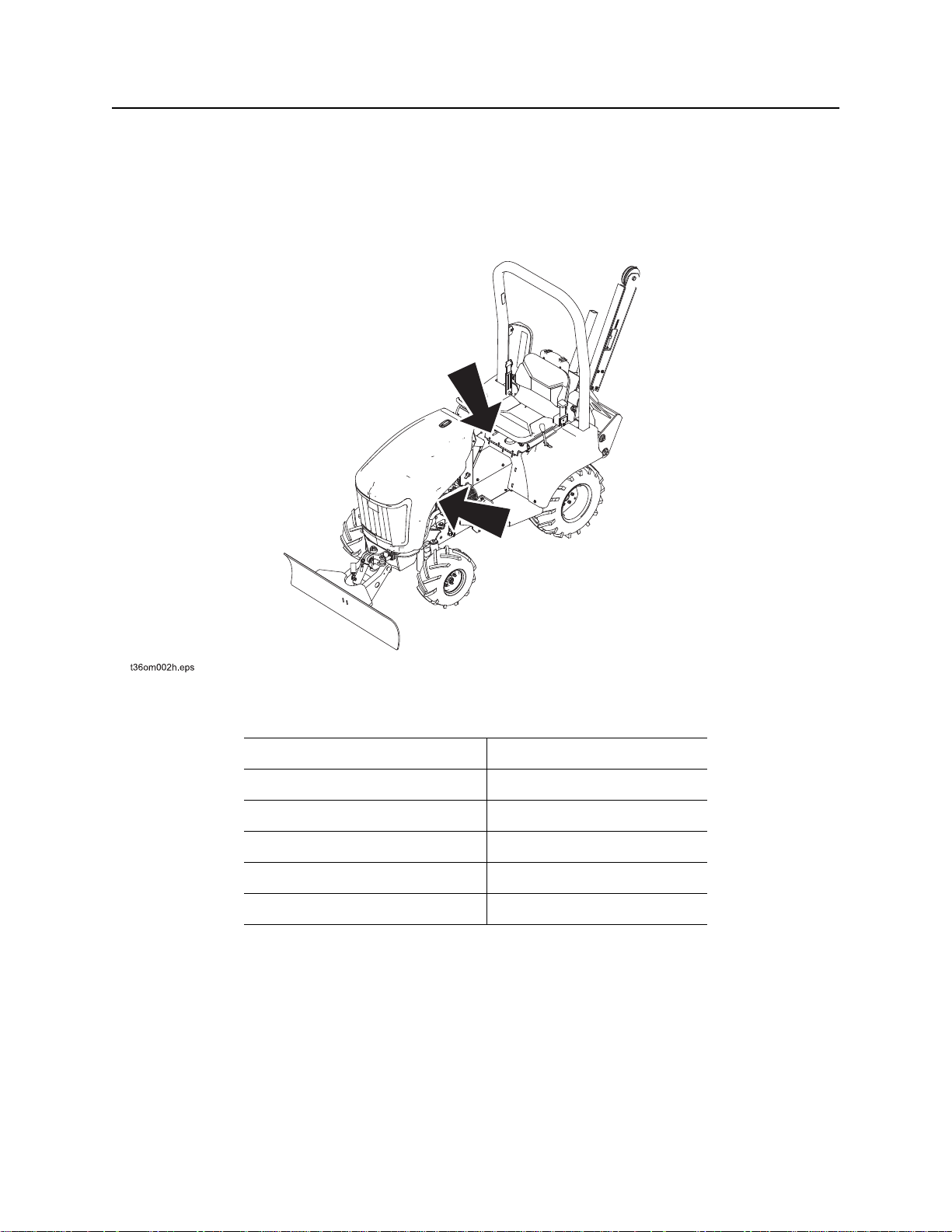
Serial Number Location
Serial Number Location
Record serial numbers and date of purchase in spaces provided. RT30 and engine serial numbers are
located as shown.
CMW
Date of manufacture
Date of purchase
RT30 serial number
Engine serial number
Rear attachment serial number
Trailer serial number
Page 4

RT30 Operator’s Manual Overview - 3
Intended Use
Intended Use
The RT30 is a riding trencher designed to install buried service lines of various sizes using the following
Ditch Witch attachments.
Attachment Max. width Max. depth
H210 trencher 8 in (203 mm) 42 in (1.1 m)
The unit is designed for operation in temperatures typically experienced in earth moving and construction
work environments. Provisions may be required to operate in extreme temperatures. Contact your Ditch
Witch dealer.
The RT30 should be used with genuine Ditch Witch chain, teeth, and sprockets. It should be operated,
serviced, and repaired only by persons familiar with its particular characteristics and acquainted with the
relevant safety procedures.
Use in any other way is considered contrary to the intended use.
Equipment Modification
This equipment was designed and built in accordance with applicable standards and regulations.
Modification of equipment could mean that it will no longer meet regulations and may not function properly
or in accordance with the operating instructions. Modification of equipment should only be made by
competent personnel possessing knowledge of applicable standards, regulations, equipment design
functionality/requirements and any required specialized testing.
CMW
Page 5
Overview - 4 RT30 Operator’s Manual
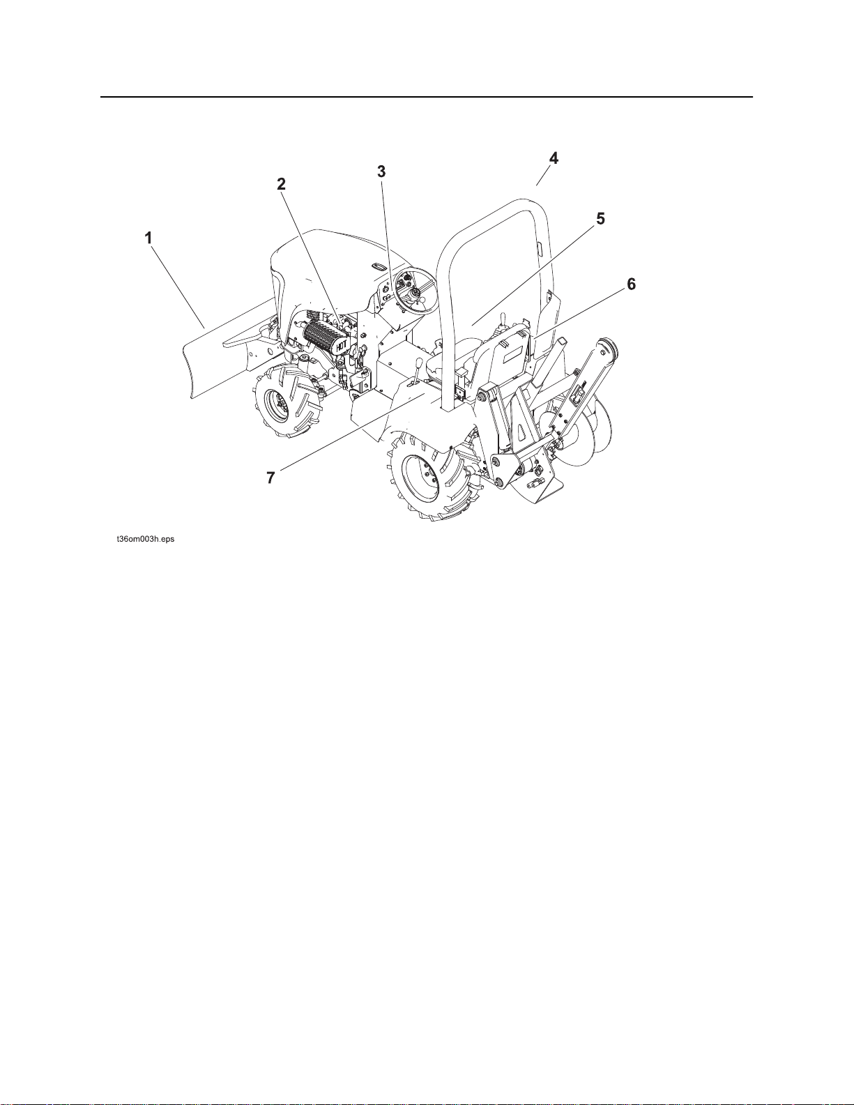
Unit Components
Unit Components
1. Backfill blade
2. Engine compartment
3. Center console
4. Rollover Protective Structure (ROPS)
5. Operator’s station
6. Right fender
7. Left fender
CMW
Page 6
RT30 Operator’s Manual Overview - 5
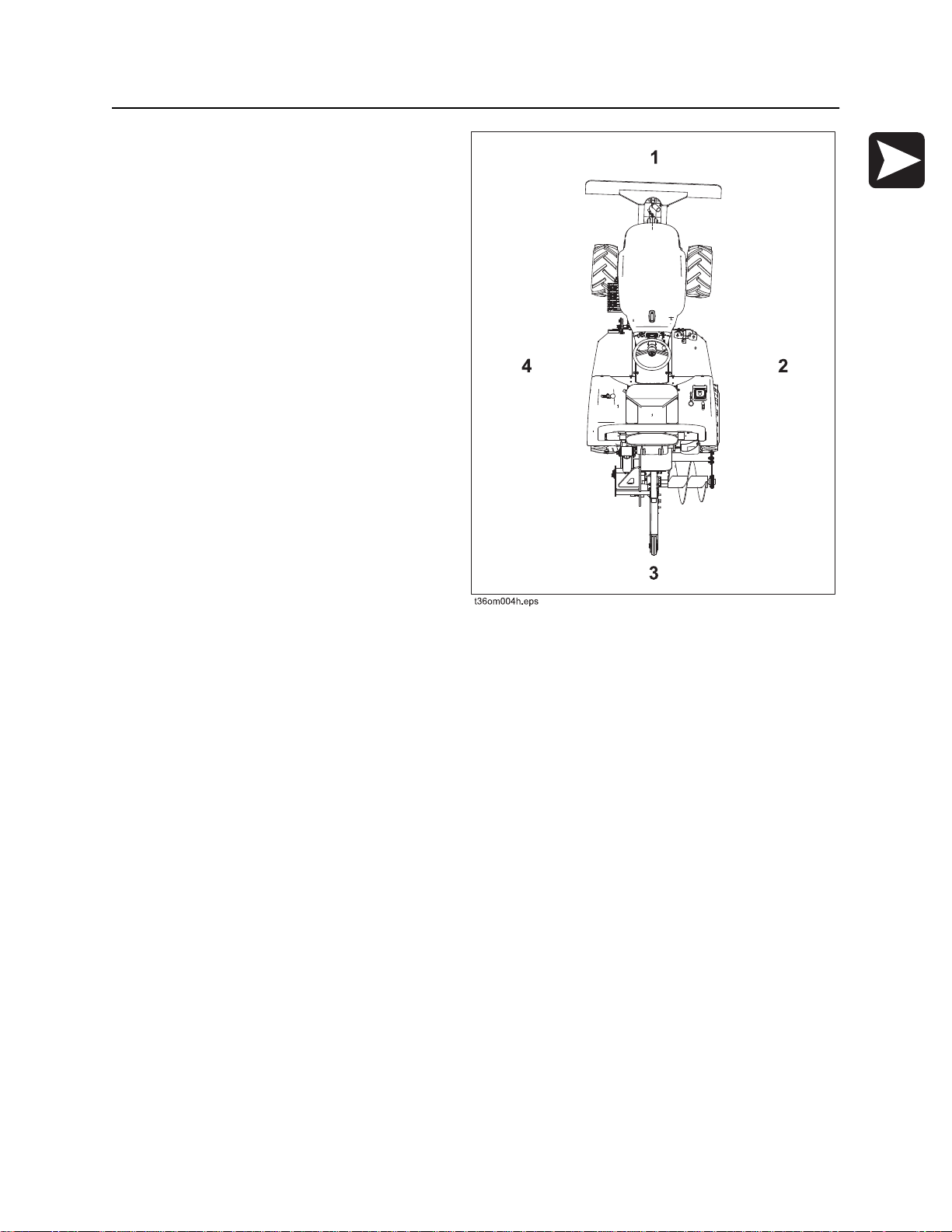
Operator Orientation
Operator Orientation
1. Front of unit
2. Right of unit
Right and left sides of machine are determined
by facing front of unit while seated at the
controls.
3. Rear of unit
4. Left of unit
About This Manual
This manual contains information for the proper use of this machine. See Operation Overview for basic
operating procedures. Cross references such as “See page 50” will direct you to detailed procedures.
Bulleted Lists
Bulleted lists provide helpful or important information or contain procedures that do not have to be
performed in a specific order.
Numbered Lists
Numbered lists contain illustration callouts or list steps that must be performed in order.
CMW
Page 7

Overview - 6 RT30 Operator’s Manual
CMW
Page 8

RT30 Operator’s Manual Foreword - 7
Foreword
This manual is an important part of your equipment. It provides safety information and operation
instructions to help you use and maintain your Ditch Witch equipment.
Read this manual before using your equipment. Keep it with the equipment at all times for future reference.
If you sell your equipment, be sure to give this manual to the new owner.
If you need a replacement copy, contact your Ditch Witch dealer. If you need assistance in locating a
dealer, visit our website at www.ditchwitch.com or write to the following address:
The Charles Machine Works, Inc.
Attn: Marketing Department
PO Box 66
Perry, OK 73077-0066
USA
The descriptions and specifications in this manual are subject to change without notice. The Charles
Machine Works, Inc. reserves the right to improve equipment. Some product improvements may have
taken place after this manual was published. For the latest information on Ditch Witch equipment, see your
Ditch Witch dealer.
Thank you for buying and using Ditch Witch equipment.
CMW
Page 9

Foreword - 8 RT30 Operator’s Manual
RT30
Operator’s Manual
by The Charles Machine Works, Inc.
, Ditch Witch, CMW, and The Underground Authority, are registered trademarks
of The Charles Machine Works, Inc.
Issue number 1.0/OM-6/13
Part number 053-2635
Copyright 2013
CMW
Page 10

RT30 Operator’s Manual Contents - 9
Contents
Overview
machine serial number, information about the type of work this machine is designed
to perform, basic machine components, and how to use this manual
Foreword
part number, revision level, and publication date of this manual, and factory contact
information
Safety
machine safety alerts and emergency procedures
Controls
machine controls, gauges, and indicators and how to use them
Operation Overview
an overview for completing a job with this machine: planning, setting up, installing
product, and restoring the jobsite; with cross references to detailed procedures
Prepare
procedures for inspecting and classifying the jobsite, planning the installation path,
and preparing the jobsite for work
Drive
procedures for startup, cold start, driving, and shutdown
1
7
11
21
33
35
41
Transport
procedures for lifting, hauling, and towing
Trench
procedures for trenching
Systems and Equipment
chain, teeth, sprockets, and optional equipment
Complete the Job
procedures for backfilling and restoring the jobsite and rinsing and storing
equipment
Service
service intervals and instructions for this machine including lubrication, replacement
of wear items, and basic maintenance
45
53
57
61
63
CMW
Page 11

Contents - 10 RT30 Operator’s Manual
Specifications
machine specifications including weights, measurements, power ratings, and fluid
capacities
Support
the warranty policy for this machine, and procedures for obtaining warranty
consideration and training
Service Record
a record of major service performed on the machine
85
91
95
CMW
Page 12

RT30 Operator’s Manual Safety - 11
Safety
Chapter Contents
Guidelines . . . . . . . . . . . . . . . . . . . . . . . . . . . . . . . . 12
Safety Alert Classifications . . . . . . . . . . . . . . . . . . 13
Safety Alerts . . . . . . . . . . . . . . . . . . . . . . . . . . . . . . 14
Emergency Procedures . . . . . . . . . . . . . . . . . . . . . 17
• Electric Strike Description . . . . . . . . . . . . . . . . . . . . . . . . . . . . . . . . . . . 17
• If an Electric Line is Damaged . . . . . . . . . . . . . . . . . . . . . . . . . . . . . . . 18
• If a Gas Line is Damaged . . . . . . . . . . . . . . . . . . . . . . . . . . . . . . . . . . . 19
• If a Fiber Optic Cable is Damaged . . . . . . . . . . . . . . . . . . . . . . . . . . . . 20
• If Machine Catches on Fire . . . . . . . . . . . . . . . . . . . . . . . . . . . . . . . . . . 20
CMW®
Page 13

Safety - 12 RT30 Operator’s Manual
Guidelines
Guidelines
Follow these guidelines before operating any jobsite equipment:
• Complete proper training and read operator’s manual before using equipment.
• Contact your local One-Call (811 in USA) or the One-Call referral number (888-258-0808 in USA and
Canada) to have underground utilities located before digging. Also contact any utilities that do not
participate in the One-Call service. Mark proposed path with white paint prior to contacting One-Call or
utilities.
• Classify jobsite based on its hazards and use correct tools and machinery, safety equipment, and work
methods for jobsite.
• Mark jobsite clearly and keep spectators away.
• Wear personal protective equipment.
• Review jobsite hazards, safety and emergency procedures, and individual responsibilities with all
personnel before work begins. Safety videos are available from your Ditch Witch
• Replace missing or damaged safety shields and safety signs.
• Use equipment carefully. Stop operation and investigate anything that does not look or feel right.
®
dealer.
• Do not operate unit where flammable gas may be present.
• Contact your Ditch Witch dealer if you have any question about operation, maintenance, or equipment
use.
CMW®
Page 14

RT30 Operator’s Manual Safety - 13
Safety Alert Classifications
Safety Alert Classifications
These classifications and the icons defined on the following pages work together to alert you to situations
which could be harmful to you, jobsite bystanders or your equipment. When you see these words and
icons in the book or on the machine, carefully read and follow all instructions. YOUR SAFETY IS AT
STAKE.
Watch for the three safety alert levels: DANGER, WARNING and CAUTION. Learn what each level
means.
indicates a hazardous situation that, if not avoided, will result in death or serious injury.
This signal word is to be limited to the most extreme situations.
indicates a hazardous situation that, if not avoided, could result in death or serious injury.
indicates a hazardous situation that, if not avoided, could result in minor or moderate
injury.
Watch for two other words: NOTICE and IMPORTANT.
NOTICE indicates information considered important, but not hazard-related (e.g., messages relating to
property damage).
IMPORTANT can help you do a better job or make your job easier in some way.
CMW®
Page 15
Safety - 14 RT30 Operator’s Manual
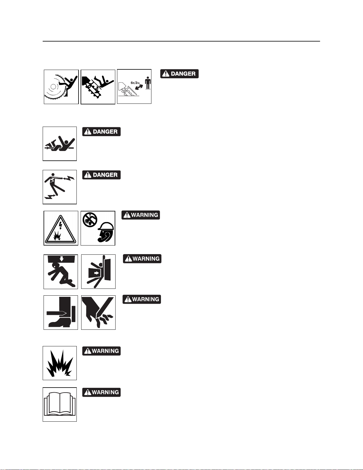
Safety Alerts
Safety Alerts
Moving digging teeth will cause death or
serious injury. Trench cave-in can cause you to fall. Stay
away.
Turning shaft will kill you or crush arm or leg. Stay away.
Electric shock. Contacting electric lines will cause death or serious injury.
Know location of lines and stay away.
correct equipment and work methods. Use and maintain proper safety
equipment.
proper procedures and equipment or stay away.
Explosion possible. Serious injury or equipment damage could occur.
Follow directions carefully.
Jobsite hazards could cause death or serious injury. Use
Crushing weight could cause death or serious injury. Use
Moving parts could cut off hand or foot. Stay away.
CMW®
Incorrect procedures could result in death, injury, or property damage.
Learn to use equipment correctly.
Page 16
RT30 Operator’s Manual Safety - 15
Safety Alerts
Fall possible. Riders can fall from machine and be injured or killed. Only
operator is allowed on machine.
Rollover possible. If machine rolls over, you could be thrown from seat and
killed or crushed. Wear seat belt.
Improper control function could cause death or serious injury. If control does
not work as described in instructions, stop machine and have it serviced.
Looking into fiber optic cable could result in permanent vision damage. Do
not look into ends of fiber optic or unidentified cable.
Pressurized fluid or air could pierce skin and cause injury or
death. Stay away.
Runaway possible. Machine could run over you or others. Learn how to use
all controls. Start and operate only from operator’s position.
Fire or explosion possible. Fumes could ignite and cause burns. No
smoking, no flame, no spark.
Avoid static electricity when fueling. Ultra Low Sulfur Diesel (ULSD) poses a
greater static ignition hazard than earlier diesel formulations. Avoid death or serious injury
from fire or explosion. Consult with your fuel system supplier to ensure the delivery system
is in compliance with fueling standards for proper grounding and bonding practices.
CMW®
Page 17
Safety - 16 RT30 Operator’s Manual
Safety Alerts
Moving traffic - hazardous situation. Death or serious injury could result.
Avoid moving vehicles, wear high visibility clothing, post appropriate warning signs.
Hot pressurized cooling system fluid could cause serious burns. Allow to
cool before servicing.
Flying objects may cause injury. Wear hard hat and safety glasses.
Hot parts may cause burns. Do not touch until cool.
Exposure to high noise levels may cause hearing loss. Wear hearing
protection.
Fall possible. Slips or trips may result in injury. Keep area clean.
Battery acid may cause burns. Avoid contact.
Improper handling or use of chemicals may result in illness, injury, or
equipment damage. Follow instructions on labels and in material safety data sheets
(MSDS).
Breathing crystalline silica dust may cause lung disease. Cutting, drilling, or
working materials such as concrete, sand, or rock containing quartz may result in exposure
to silica dust. Use dust control methods or appropriate breathing protection when exposed
to silica dust.
CMW®
Page 18
RT30 Operator’s Manual Safety - 17
Emergency Procedures
Emergency Procedures
Jobsite hazards could cause death or serious injury. Use
correct equipment and work methods. Use and maintain proper safety
equipment.
Before operating any equipment, review emergency procedures and check that all safety precautions have
been taken.
EMERGENCY SHUTDOWN - Turn ignition switch to stop position or push remote engine stop button (if
equipped).
Electric Strike Description
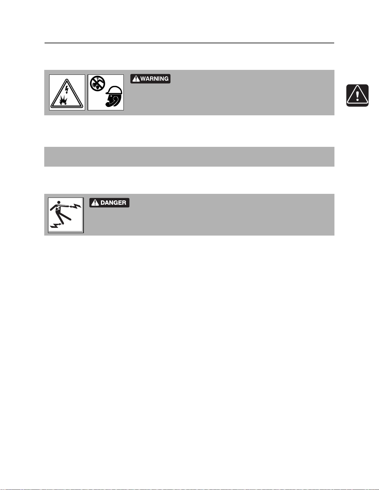
Electric shock. Contacting electric lines will cause death or serious injury.
Know location of lines and stay away.
When working near electric cables, remember the following:
• Electricity follows all paths to ground, not just path of least resistance.
• Pipes, hoses, and cables will conduct electricity back to all equipment.
• Low voltage current can injure or kill. Many work-related electrocutions result from contact with less
than 440 volts.
Most electric strikes are not noticeable, but indications of a strike include:
• power outage
• smoke
• explosion
• popping noises
• arcing electricity
If any of these occur, assume an electric strike has occurred.
CMW®
Page 19

Safety - 18 RT30 Operator’s Manual
Emergency Procedures
If an Electric Line is Damaged
If you suspect an electric line has been damaged and you are on tractor, DO NOT MOVE. Remain on
tractor and take the following actions. The order and degree of action will depend upon the situation.
• Warn people nearby that an electric strike has occurred. Instruct them to leave the area and contact
utility.
• Raise attachments and drive from immediate area.
• Contact utility company to shut off power.
• Do not return to jobsite or allow anyone into area until given permission by utility company.
If you suspect an electric line has been damaged and you are off tractor, DO NOT TOUCH TRACTOR.
Take the following actions. The order and degree of action will depend upon the situation.
• LEAVE AREA. The ground surface may be electrified, so take small steps with feet close together to
reduce the hazard of being shocked from one foot to the other. For more information, contact your
Ditch Witch dealer.
• Contact utility company to shut off power.
• Do not return to jobsite or allow anyone into area until given permission by utility company.
CMW®
Page 20
RT30 Operator’s Manual Safety - 19
Emergency Procedures
If a Gas Line is Damaged
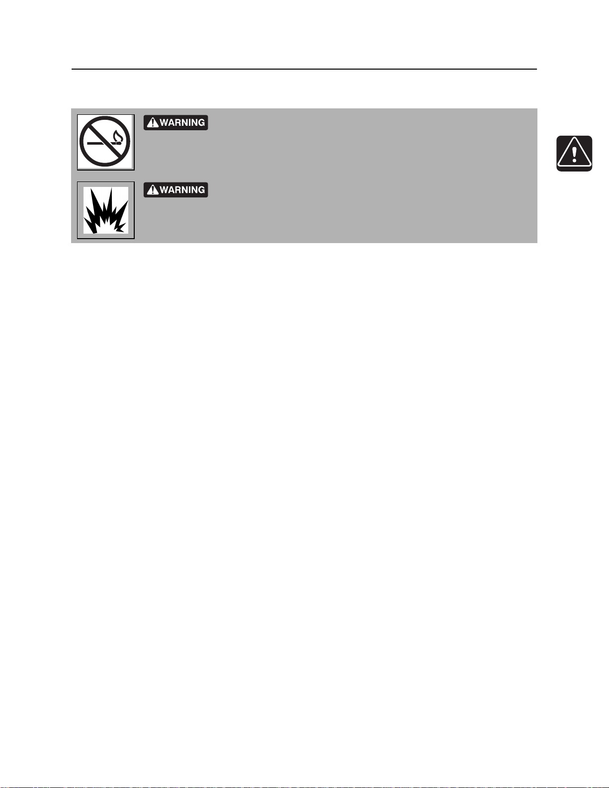
Fire or explosion possible. Fumes could ignite and cause burns. No
smoking, no flame, no spark.
Explosion possible. Serious injury or equipment damage could occur.
Follow directions carefully.
If you suspect a gas line has been damaged, take the following actions. The order and degree of action will
depend on the situation.
• Immediately shut off engine(s), if this can be done safely and quickly.
• Remove any ignition source(s), if this can be done safely and quickly.
• Warn others that a gas line has been cut and that they should leave the area.
• Leave jobsite as quickly as possible.
• Immediately call your local emergency phone number and utility company.
• If jobsite is along street, stop traffic from driving near jobsite.
• Do not return to jobsite until given permission by emergency personnel and utility company.
CMW®
Page 21

Safety - 20 RT30 Operator’s Manual
Emergency Procedures
If a Fiber Optic Cable is Damaged
Do not look into cut ends of fiber optic or unidentified cable. Vision damage can occur.
If Machine Catches on Fire
Perform emergency shutdown procedure and then take the following actions. The order and degree of
action will depend on the situation.
• Immediately move battery disconnect switch (if equipped and accessible) to disconnect position.
• If fire is small and fire extinguisher is available, attempt to extinguish fire.
• If fire cannot be extinguished, leave area as quickly as possible and contact emergency personnel.
CMW®
Page 22

RT30 Operator’s Manual Controls - 21
Controls
Chapter Contents
Center Console . . . . . . . . . . . . . . . . . . . . . . . . . . . 22
• Indicators . . . . . . . . . . . . . . . . . . . . . . . . . . . . . . . . . . . . . . . . . . . . . . . 22
• Controls . . . . . . . . . . . . . . . . . . . . . . . . . . . . . . . . . . . . . . . . . . . . . . . . 25
Machine . . . . . . . . . . . . . . . . . . . . . . . . . . . . . . . . . . 27
Seat . . . . . . . . . . . . . . . . . . . . . . . . . . . . . . . . . . . . . 31
CMW
Page 23
Controls - 22 RT30 Operator’s Manual
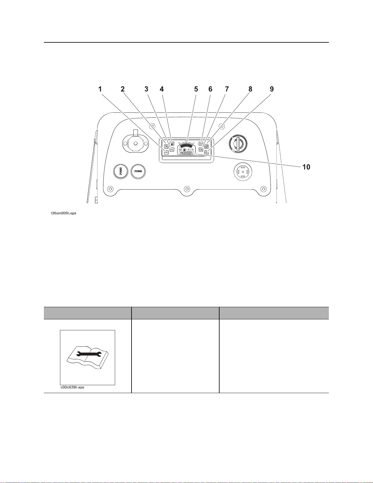
Center Console
Center Console
Indicators
1. Not used
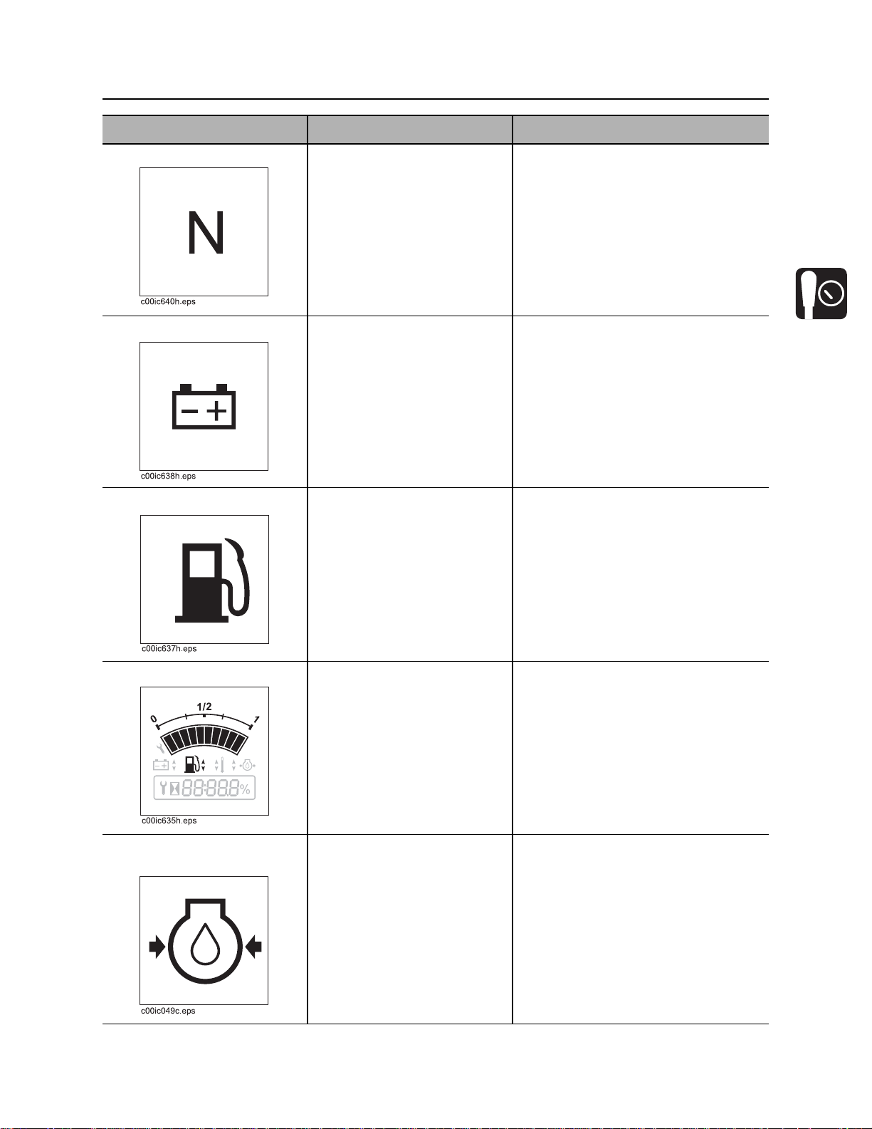
2. Neutral indicator
3. Not used
4. Not used
5. Fuel gauge
Item Description Notes
1. Not used Light will come on briefly
when engine is started.
6. Engine low oil pressure indicator
7. Coolant temperature indicator
8. Hydraulic fluid temperature indicator
9. Not used
10. Hourmeter
CMW
Page 24
RT30 Operator’s Manual Controls - 23
Center Console
Item Description Notes
2. Neutral indicator Lights when start interlock
system conditions are met.
Light will come on briefly
when engine is started.
3. Not used Light will come on briefly
when engine is started.
4. Not used Light will come on briefly
when engine is started.
To start engine,
• operator must be in seat,
• attachment drive control must be
in neutral, and
• ground drive control must be in
neutral.
5. Fuel gauge Displays fuel level in tank. Fuel tank holds 5 gal (19 L).
NOTICE: Use ultra low sulfur fuel
only.
6. Engine low oil pressure
indicator
Lights when oil pressure falls
below 8-12 psi (.5-.8 bar).
Light will come on briefly
when engine is started.
If light remains on:
• Turn off engine.
• Check oil level.
• If pressure is still low, consult
engine manual.
CMW
Page 25
Controls - 24 RT30 Operator’s Manual
Center Console
Item Description Notes
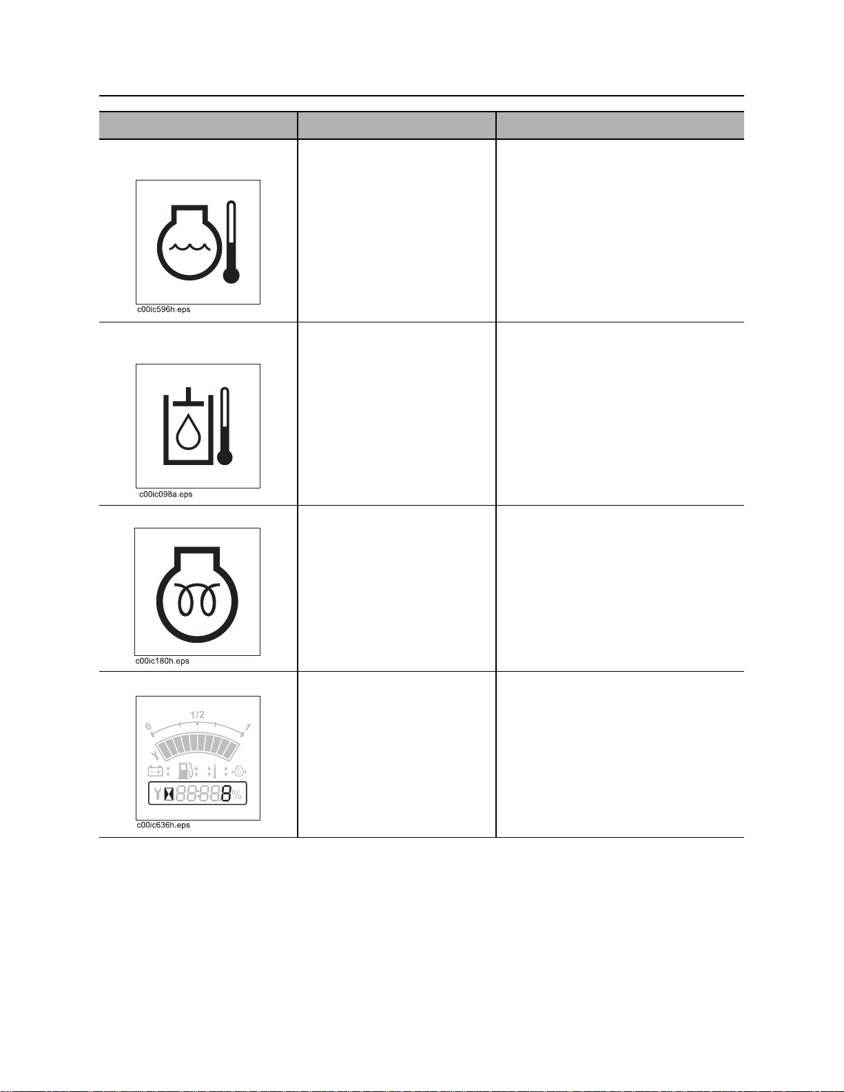
7. Coolant temperature
indicator
8. Hydraulic fluid
temperature indicator
9. Not used Light will come on briefly
Lights if engine coolant
temperature rises above 275°
F (135° C). Light will come on
briefly when engine is started.
Lights if hydraulic fluid
overheats. Light will come on
briefly when engine is started.
when engine is started.
If light remains on:
• Turn off engine and let it cool.
• Check fan belt tension.
• Check for low coolant level.
• Check cooling fins for dirt and
debris.
If light remains on:
• Check that engine fan is turning
when engine is running.
• Turn off engine and let it cool.
• Check hydraulic fluid level.
• Check front of hydraulic fluid
cooler for debris.
10. Hourmeter Records engine operating
time.
CMW
Use engine operating times to
schedule service.
Page 26
RT30 Operator’s Manual Controls - 25
Center Console
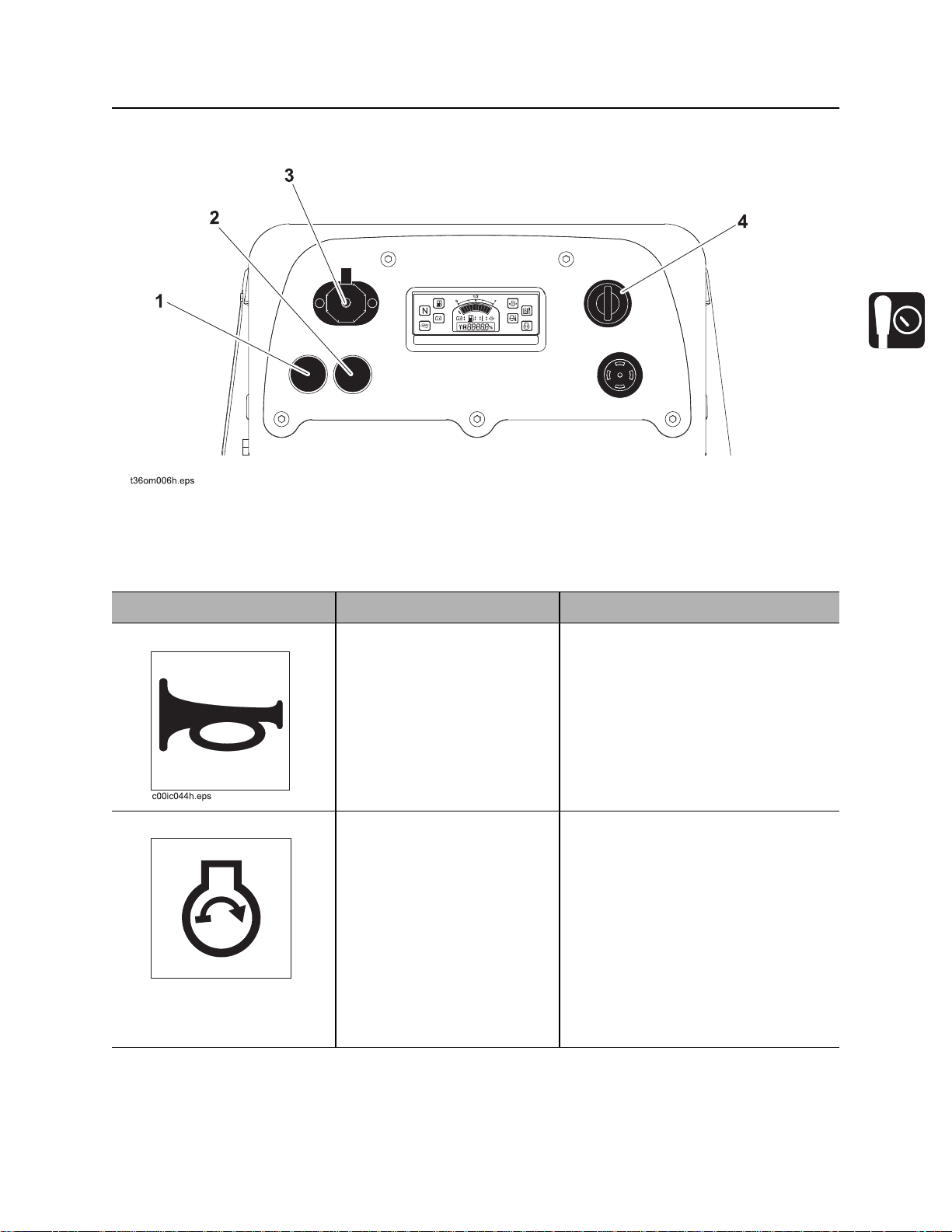
Controls
1. Horn
2. Cold start control
Item Description Notes
1. Horn To sound horn, press.
2. Cold start button To help start cold engine, turn
ignition switch to first position.
Press cold start button as
directed in notes.
Release button, then turn
ignition switch all the way
c00ic152h.eps
clockwise to start.
3. Auxiliary outlet
4. Ignition switch
IMPORTANT: Press cold start button
according to temperatures below.
• If ambient temperature is below
40° F (4° C), press and hold
button for 5 seconds.
• If ambient temperature is below
20° F (-7° C), press and hold
button for 10 seconds.
• Do not press button for more than
20 seconds continuously.
CMW
Page 27
Controls - 26 RT30 Operator’s Manual
Center Console
Item Description Notes
3. Auxiliary outlet Provides power for other
equipment.
c00ic179h.eps
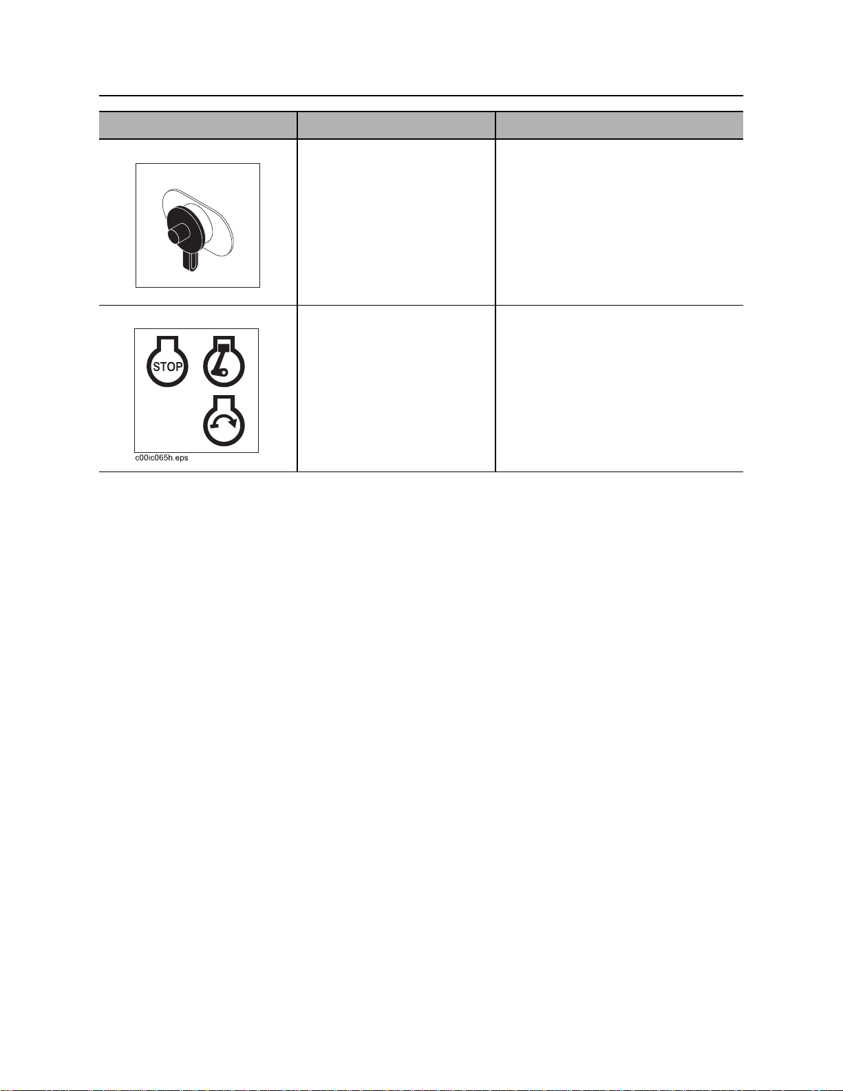
4. Ignition switch To start engine, insert key and
turn clockwise.
To stop engine, turn
counterclockwise.
Power output is 12V, 5A.
If engine does not start on first
attempt, check that all start interlock
requirements have been met, return
switch to STOP, and try again.
CMW
Page 28
RT30 Operator’s Manual Controls - 27
Machine
Machine
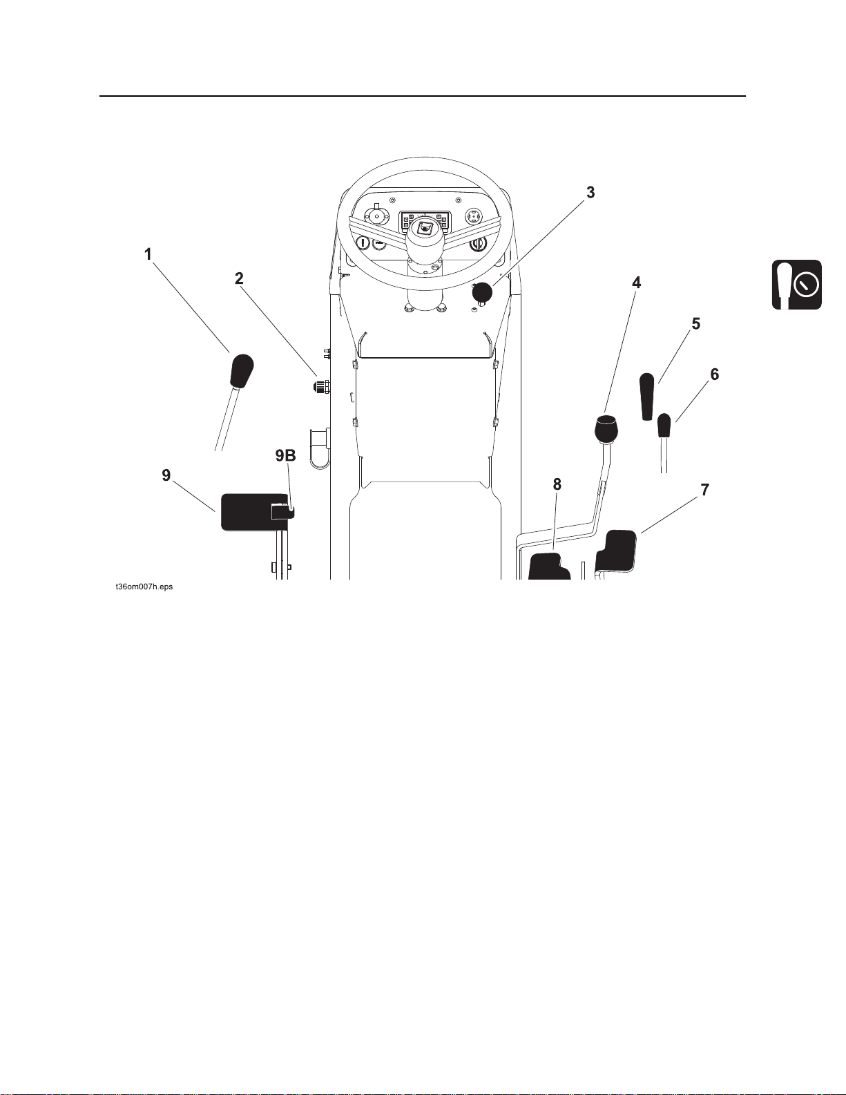
1. Attachment speed/direction control
2. Battery disconnect switch
3. Throttle
4. Ground drive forward speed control
5. Backfill blade control
6. Boom lift control
7. Ground drive foot control - forward
8. Ground drive foot control - reverse
9. Parking brake
9B. Parking brake release
CMW
Page 29
Controls - 28 RT30 Operator’s Manual
Machine
Item Description Notes
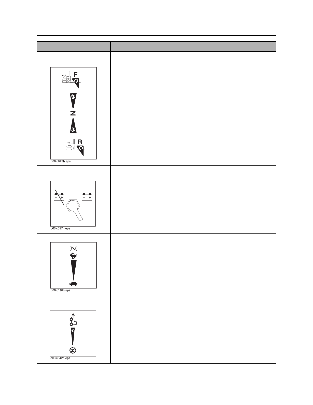
1. Attachment speed/
direction control
2. Battery disconnect
switch
To rotate attachment forward,
push.
To rotate attachment
backward, pull.
To go faster in either
direction, move farther from
center.
To stop attachment rotation,
move to neutral.
To disconnect, move switch
so that indicator points left.
To connect, move switch so
that indicator points right.
Control does not return to neutral
when released.
3. Throttle To increase engine speed,
push.
To decrease engine speed,
pull.
4. Ground drive forward
speed control
CMW
To go forward when
trenching, push.
To go faster, move farther
forward.
To stop and enable reverse
(R) foot control to function,
move to neutral.
Control does not automatically return
to neutral position when released.
Page 30
RT30 Operator’s Manual Controls - 29
Machine
Item Description Notes
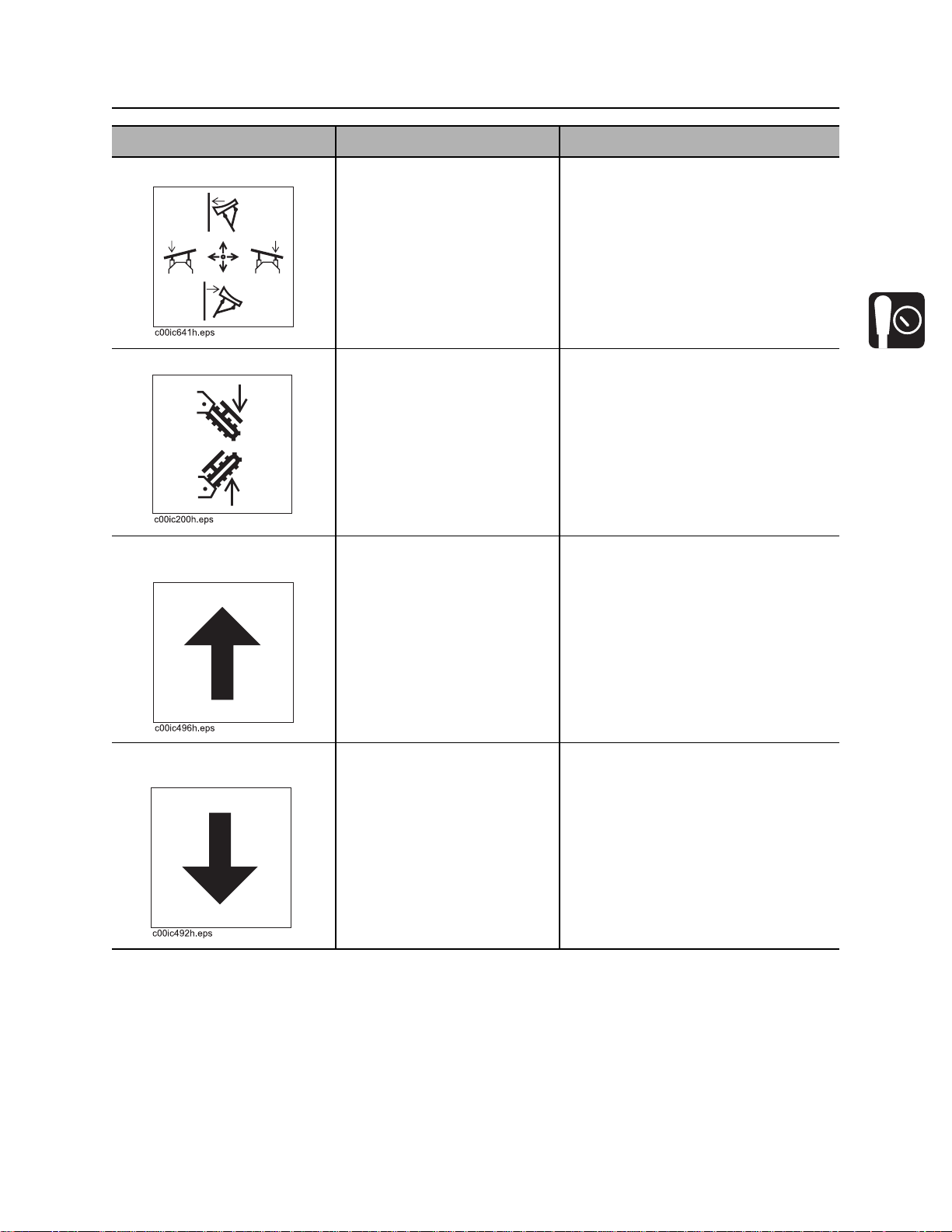
5. Backfill blade control To lower blade, push.
To raise blade, pull.
To swing blade to right, move
right.
To swing blade to left, move
left.
6. Boom lift control To lower, push.
To raise, pull.
7. Ground drive foot
control - forward
8. Ground drive foot
control - reverse
To move tractor forward, push
pedal.
To increase speed, push
pedal farther.
To stop, release pedal.
To move tractor backward,
push pedal.
To increase speed, push
pedal farther.
To stop, release pedal.
IMPORTANT: If you are overriding the
hand control setting, releasing the
foot control will return tractor to the
hand control setting.
IMPORTANT: Pedal functions only
when hand control is in neutral
position.
CMW
Page 31

Controls - 30 RT30 Operator’s Manual
Machine
Item Description Notes
9. Parking brake To engage parking brake,
push pedal (9).
To release parking brake,
press tab (9B) to allow pedal
to return to disengaged
position.
c00ic268h.eps
CMW
Page 32

RT30 Operator’s Manual Controls - 31
Seat
Seat
1. Seat belt 2. Seat slide control
Item Description Notes
1. Seat belt To fasten, insert latch into
buckle. Adjust until seat belt
is low and tight.
To release, lift top of buckle.
2. Seat slide control To slide seat forward or
backward, pull or push left,
then adjust seat.
To lock seat in place, release.
CMW
Page 33

Controls - 32 RT30 Operator’s Manual
Seat
CMW
Page 34

RT30 Operator’s Manual Operation Overview - 33
Operation Overview
Chapter Contents
Planning. . . . . . . . . . . . . . . . . . . . . . . . . . . . . . . . . . 34
Trenching. . . . . . . . . . . . . . . . . . . . . . . . . . . . . . . . . 34
Leaving Jobsite. . . . . . . . . . . . . . . . . . . . . . . . . . . . 34
CMW
Page 35

Operation Overview - 34 RT30 Operator’s Manual
Planning
Planning
1. Gather information about jobsite. See page 36.
2. Inspect jobsite. See page 37.
3. Classify jobsite. See page 38.
4. Select chain and teeth to match your soil type, if necessary. See page 58.
5. Check supplies and prepare equipment. See page 40.
6. Haul equipment to jobsite. See page 49.
Trenching
1. Start unit. See page 42.
2. Position tractor and controls. See page 54.
3. Begin trenching. See page 55.
4. Complete the installation. See page 55.
5. Backfill the trench. See page 62.
6. Shut down tractor. See page 44.
Leaving Jobsite
1. Backfill if necessary. See page 62.
2. Rinse equipment. See page 62.
3. Stow tools. See page 62.
4. Haul equipment away from jobsite. See page 49.
CMW
Page 36

RT30 Operator’s Manual Prepare - 35
Prepare
Chapter Contents
Gather Information . . . . . . . . . . . . . . . . . . . . . . . . . 36
• Review Job Plan . . . . . . . . . . . . . . . . . . . . . . . . . . . . . . . . . . . . . . . . . . 36
• Notify One-Call Services . . . . . . . . . . . . . . . . . . . . . . . . . . . . . . . . . . . . 36
• Arrange for Traffic Control. . . . . . . . . . . . . . . . . . . . . . . . . . . . . . . . . . . 36
• Plan for Emergency Services . . . . . . . . . . . . . . . . . . . . . . . . . . . . . . . . 36
Inspect Site . . . . . . . . . . . . . . . . . . . . . . . . . . . . . . . 37
• Identify Hazards . . . . . . . . . . . . . . . . . . . . . . . . . . . . . . . . . . . . . . . . . . 37
Classify Jobsite. . . . . . . . . . . . . . . . . . . . . . . . . . . . 38
• Inspect Jobsite . . . . . . . . . . . . . . . . . . . . . . . . . . . . . . . . . . . . . . . . . . . 38
• Select a Classification . . . . . . . . . . . . . . . . . . . . . . . . . . . . . . . . . . . . . . 38
• Apply Precautions . . . . . . . . . . . . . . . . . . . . . . . . . . . . . . . . . . . . . . . . . 39
Check Supplies and Prepare Equipment . . . . . . . 40
• Supplies . . . . . . . . . . . . . . . . . . . . . . . . . . . . . . . . . . . . . . . . . . . . . . . . 40
• Fluid Levels . . . . . . . . . . . . . . . . . . . . . . . . . . . . . . . . . . . . . . . . . . . . . . 40
• Condition and Function . . . . . . . . . . . . . . . . . . . . . . . . . . . . . . . . . . . . . 40
• Accessories. . . . . . . . . . . . . . . . . . . . . . . . . . . . . . . . . . . . . . . . . . . . . . 40
CMW
Page 37

Prepare - 36 RT30 Operator’s Manual
Gather Information
Gather Information
A successful job begins before you dig. The first step in planning is reviewing information already available
about the job and jobsite.
Review Job Plan
Review blueprints or other plans. Check for information about existing or planned structures, elevations, or
proposed work that may be taking place at the same time.
Notify One-Call Services
Contact your local One-Call (811 in USA) or the One-Call referral number (888-258-0808 in USA and
Canada) to have underground utilities located before digging. Also contact any utilities that do not
participate in the One-Call service.
Arrange for Traffic Control
If working near a road or other traffic area, contact local authorities about safety procedures and
regulations.
Plan for Emergency Services
Have the telephone numbers for local emergency and medical facilities on hand. Check that you will have
access to a telephone.
CMW
Page 38

RT30 Operator’s Manual Prepare - 37
Inspect Site
Inspect Site
Inspect jobsite before transporting equipment. Check for the following:
• changes in elevation such as hills or other open trenches
• obstacles such as buildings, railroad crossings, or streams
• signs of utilities (See “Inspect Jobsite” on page 38.)
• traffic
• access
• soil type and condition
Identify Hazards
Identify safety hazards and classify jobsite. See “Classify Jobsite” on page 38.
Jobsite hazards could cause death or serious injury. Use
correct equipment and work methods. Use and maintain proper safety
equipment.
To help avoid injury:
• Wear personal protective equipment including hard hat, safety eye wear, and hearing protection.
• Do not wear jewelry or loose clothing.
• Notify One-Call and companies which do not subscribe to One-Call.
• Comply with all utility notification regulations before digging or drilling.
• Verify location of previously marked underground hazards.
• Mark jobsite clearly and keep spectators away.
Remember, jobsite is classified by hazards in place -- not by line being installed.
CMW
Page 39

Prepare - 38 RT30 Operator’s Manual
Classify Jobsite
Classify Jobsite
Inspect Jobsite
• Follow U.S. Department of Labor regulations on excavating and trenching (Part 1926, Subpart P) and
other similar regulations.
• Contact your local One-Call (811 in USA) or the One-Call referral number (888-258-0808 in USA and
Canada) to have underground utilities located before digging. Also contact any utilities that do not
participate in the One-Call service.
• Inspect jobsite and perimeter for evidence of underground hazards, such as:
– “buried utility” notices
– utility facilities without overhead lines
– gas or water meters
– junction boxes
– drop boxes
– light poles
– manhole covers
– sunken ground
• Have an experienced locating equipment operator sweep area within 20’ (6 m) to each side of trench
path. Verify previously marked line and cable locations.
• Mark location of all buried utilities and obstructions.
• Classify jobsite.
Select a Classification
Jobsites are classified according to underground hazards present.
If working . . . then classify jobsite as . . .
within 10’ (3 m) of a buried electric line electric
within 10’ (3 m) of a natural gas line natural gas
in sand, granite, or concrete which is capable of producing
crystalline silica (quartz) dust
within 10’ (3 m) of any other hazard other
IMPORTANT: If you have any doubt about jobsite classification, or if jobsite might contain unmarked
hazards, take steps outlined previously to identify hazards and classify jobsite before working.
crystalline silica (quartz) dust
CMW
Page 40

RT30 Operator’s Manual Prepare - 39
Classify Jobsite
Apply Precautions
Once classified, precautions appropriate for jobsite must be taken.
Electric Jobsite Precautions
Use one or both of these methods.
• Expose line by careful hand digging or soft excavation.
• Have service shut down while work is in progress. Have electric company test lines before returning
them to service.
Natural Gas Jobsite Precautions
In addition to positioning equipment upwind from gas lines, use one or both of these methods.
• Expose lines by careful hand digging or soft excavation.
• Have gas shut off while work is in progress. Have gas company test lines before returning them to
service.
Crystalline Silica (Quartz) Dust Precautions
Crystalline silica dust is a naturally occuring substance found in soil, sand, concrete, granite, and quartz.
Breathing silica dust particles while cutting, drilling, or working materials may cause lung disease or
cancer. To reduce exposure:
• Use water spray or other means to control dust.
• Refer to U.S. Department of Labor Occupational Safety and Health Administration guidelines to learn
more about appropriate breathing protection and permissible exposure limits.
Other Jobsite Precautions
You may need to use different methods to safely avoid other underground hazards. Talk with those
knowledgeable about hazards present at each site to determine which precautions should be taken or if
job should be attempted.
CMW
Page 41

Prepare - 40 RT30 Operator’s Manual
Check Supplies and Prepare Equipment
Check Supplies and Prepare Equipment
Supplies
• fuel
• keys
• personal protective equipment, such as hard hat and safety glasses
Fluid Levels
• fuel
• hydraulic fluid
• battery charge
• engine oil
Condition and Function
• digging chain and teeth
• fan belts
• light bulbs
• filters (air, oil, hydraulic)
• tires
• pumps and motors
• hoses and valves
• signs, guards, and shields
Accessories
Fire Extinguisher
If required, mount a fire extinguisher near the power unit but away from possible points of ignition. The fire
extinguisher should always be classified for both oil and electric fires. It should meet legal and regulatory
requirements.
CMW
Page 42

RT30 Operator’s Manual Drive - 41
Drive
Chapter Contents
Start Unit . . . . . . . . . . . . . . . . . . . . . . . . . . . . . . . . . 42
Drive. . . . . . . . . . . . . . . . . . . . . . . . . . . . . . . . . . . . . 44
Shut Down . . . . . . . . . . . . . . . . . . . . . . . . . . . . . . . . 44
CMW
Page 43

Drive - 42 RT30 Operator’s Manual
Start Unit
Start Unit
Before operating tractor, read engine manufacturer’s starting and operating instructions. Follow
instructions for new engine break-in.
Incorrect procedures could result in death, injury, or property damage.
Learn to use equipment correctly.
To help avoid injury:
• Read operator’s manual before operating equipment. Follow instructions carefully. Contact Ditch
Witch dealership for operation information or demonstration.
• Wear hard hat, safety glasses, and other protective equipment required by job. Do not wear jewelry
or loose clothing that can catch on controls.
Runaway possible. Machine could run over you or others. Learn how to
use all controls. Start and operate only from operator’s position.
Rollover possible. If machine rolls over, you could be thrown from seat
and killed or crushed. Wear seat belt.
CMW
Page 44

RT30 Operator’s Manual Drive - 43
Start Unit
1. Fasten and adjust seat belt.
2. Check that ground drive control and attachment speed/direction control are in neutral.
3. Move throttle to idle.
4. Verify that parking brake is engaged..
Explosion possible. Serious injury or equipment damage could
occur. Follow directions carefully.
To help avoid injury: Do not use ether or any other type of aerosol starting fluid when unit is
equipped with cold start option.
5. If needed, press cold start switch up to 20 seconds (see page 25) and release.
6. Turn ignition switch all the way clockwise to start tractor. Warning alarm will sound. Indicators will light.
• If engine does not crank, verify start interlock conditions are met. See page 23 for start interlock
information.
• If engine turns but does not start within 10 seconds, allow starter to cool before trying to start
again.
Improper control function could cause death or serious injury.
To help avoid injury: Stop machine and have it serviced if control does not work
as described in instructions.
IMPORTANT: Machine will not start if start interlock requirements are not met. See page 23 for
start interlock information.
7. Run engine at half-throttle or less for five minutes before operating tractor. During warmup, check that
all controls work properly.
CMW
Page 45

Drive - 44 RT30 Operator’s Manual
Drive
Drive
Moving traffic – hazardous situation. Death or serious injury could result.
Avoid moving vehicles, wear high visibility clothing, post appropriate warning signs.
To help avoid injury:
• Drive carefully in congested areas. Know machine’s clearance and turning radius.
• Keep attachments low when operating on slope. Drive slowly and cautiously.
EMERGENCY SHUTDOWN: Turn ignition switch to STOP.
1. Turn on lights as needed.
2. Raise backfill blade and all attachments.
3. Release parking brake.
4. Adjust throttle.
5. Move ground drive control to forward or reverse or press forward (F) or reverse (R) foot pedal.
The ground drive forward (F) foot pedal can override the ground drive forward speed control lever. Use
the override feature when trenching.
• When driving or backfilling, use only the forward (F) and reverse (R) foot pedals to control speed
and direction.
• When trenching, use hand lever to set travel speed and use the forward (F) foot pedal to adjust
speed temporarily when digging conditions change. When original digging condition resumes,
release foot pedal to return to original speed.
Shut Down
1. When job is complete, move ground drive control to neutral.
2. Set parking brake.
3. Lower all attachments to ground.
4. Move throttle to idle for 3 minutes to cool engine.
5. Turn ignition switch to STOP. If leaving machine unattended, remove key.
6. For maintenance or long-term storage, turn battery disconnect switch, if equipped, to the disconnect
position.
CMW
Page 46

RT30 Operator’s Manual Transport - 45
Transport
Chapter Contents
Lift . . . . . . . . . . . . . . . . . . . . . . . . . . . . . . . . . . . . . . 46
• Points . . . . . . . . . . . . . . . . . . . . . . . . . . . . . . . . . . . . . . . . . . . . . . . . . . 46
• Procedure . . . . . . . . . . . . . . . . . . . . . . . . . . . . . . . . . . . . . . . . . . . . . . . 47
Tie Down . . . . . . . . . . . . . . . . . . . . . . . . . . . . . . . . . 48
• Points . . . . . . . . . . . . . . . . . . . . . . . . . . . . . . . . . . . . . . . . . . . . . . . . . . 48
• Procedure . . . . . . . . . . . . . . . . . . . . . . . . . . . . . . . . . . . . . . . . . . . . . . . 48
Haul . . . . . . . . . . . . . . . . . . . . . . . . . . . . . . . . . . . . . 49
• Procedure . . . . . . . . . . . . . . . . . . . . . . . . . . . . . . . . . . . . . . . . . . . . . . . 50
Tow . . . . . . . . . . . . . . . . . . . . . . . . . . . . . . . . . . . . . 52
• Procedure . . . . . . . . . . . . . . . . . . . . . . . . . . . . . . . . . . . . . . . . . . . . . . . 52
CMW
Page 47

Transport - 46 RT30 Operator’s Manual
Lift
Lift
Crushing weight. If load falls or moves it could kill or crush you. Use
proper procedures and equipment or stay away.
Incorrect procedures could result in death, injury, or property damage.
Learn to use equipment correctly.
Points
Lifting points are identified by lifting decals. Lifting at other points is unsafe
and can damage machinery.
CMW
Page 48

RT30 Operator’s Manual Transport - 47
Lift
Procedure
Tractor
This machine is not configured for lifting. If the machine must be lifted, load machine into a container or
onto a platform appropriate for lifting. See “Specifications” for weight of machine.
H210 Trencher
Use crane capable of supporting the
equipment's size and weight. See page 85 or
measure and weigh equipment before lifting.
NOTICE: Do not lift tractor with installed
attachment.
CMW
Page 49

Transport - 48 RT30 Operator’s Manual
Tie Down
Tie Down
Incorrect procedures could result in death, injury, or property damage.
Learn to use equipment correctly.
Points
Tiedown points are identified by tiedown decals. Securing to trailer at other
points is unsafe and can damage machinery.
Procedure
Tractor
Attach chains at front and attachment tiedown
points. Make sure chains are tight before
transporting unit.
CMW
Page 50

RT30 Operator’s Manual Transport - 49
Haul
H210 Trencher
Attach chains at tiedown point. Make sure
chains are tight before transporting unit.
Haul
Incorrect procedures could result in death, injury, or property damage.
Learn to use equipment correctly.
To help avoid injury:
• Read trailer operator’s manual before loading or transporting your machine. Incorrectly loaded
machine can slip or cause trailer sway.
• Ensure that tow vehicle has proper tow capacity rating.
• Attach trailer to tow vehicle before loading or unloading.
• Park, load, and unload trailer on level ground.
• Check that unit and trailer do not exceed size or weight regulations.
• Load trailer correctly to avoid trailer swaying. Ten to fifteen percent of total vehicle weight
(equipment plus trailer) must be on tongue to help prevent trailer sway.
• Connect safety chains to tow vehicle. Attach left chain to right side of tow vehicle and vice versa to
cradle hitch. Do not connect to pintle hook or hitch ball.
• Connect breakaway switch cable to tow vehicle. Do not connect to pintle hook or hitch ball.
CMW
Page 51

Transport - 50 RT30 Operator’s Manual
Haul
Procedure
Inspect Trailer
1. Check hitch for wear and cracks. Lubricate if needed.
2. Check battery for 12V charge.
3. Inspect lights for cleanliness and correct operation. Inspect reflectors and replace if needed.
4. Check tire pressure. Check lug nut torque with a torque wrench. Adjust if needed.
5. Ensure trailer brakes are adjusted to come on in synchronization with tow vehicle brakes.
6. Check ramps and trailer bed for cracks.
Load
Crushing weight. If load falls or moves it could kill or crush you. Use
proper procedures and equipment or stay away.
To help avoid injury:
• Attach trailer to tow vehicle before loading or unloading.
• Load and unload trailer on level ground.
• Block trailer wheels.
Rollover possible. If machine rolls over, you could be thrown from seat
and killed or crushed. Wear seat belt.
1. Fasten and adjust seat belt.
2. Start tractor. See page 42 for proper start-up procedures.
3. Raise attachment, but keep it low.
4. Release parking brake.
5. Slowly drive tractor onto trailer.
6. Position tractor on trailer deck for proper weight distribution.
7. Engage parking brake.
8. Lower attachment to trailer bed and turn tractor off. See page 44 for proper shutdown procedures.
9. Attach chains to tractor and attachments where tiedown decals are located. See page 48.
CMW
Page 52

RT30 Operator’s Manual Transport - 51
Haul
Unload
Crushing weight. If load falls or moves it could kill or crush you. Use
proper procedures and equipment or stay away.
To help avoid injury:
• Attach trailer to tow vehicle before loading or unloading.
• Load and unload trailer on level ground.
• Block trailer wheels.
Rollover possible. If machine rolls over, you could be thrown from seat
and killed or crushed. Wear seat belt.
1. Lower trailer or ramps.
2. Remove chains from tiedowns.
3. Fasten and adjust seat belt.
4. Start tractor. See page 42 for proper start-up procedures.
5. Raise attachment, but keep it low.
6. Disengage parking brake.
7. Slowly back unit down trailer or ramps.
CMW
Page 53

Transport - 52 RT30 Operator’s Manual
Tow
Tow
Incorrect procedures could result in death, injury, or property damage.
Learn to use equipment correctly.
Under normal conditions, tractor should not be towed. If tractor becomes disabled and towing is
necessary:
• Do not tow for more than 200 yd (180 m).
• Tow at less than 1 mph (1.6 km/h).
• Use maximum towing force of 1.5 times unit weight.
Procedure
NOTICE: When bypass valve is open, unit
has no brakes.
1. Attach tow line to all available tiedown
points facing towing vehicle.
2. Bypass hydraulic system.
Remove tunnel cover and loosen bypass
valve (shown) two turns. Valve is on top of
front pump.
3. Fasten seat belt.
4. Disengage parking brake.
5. Check that ground drive and attachment
speed/direction controls are in neutral
position.
CMW
Page 54

RT30 Operator’s Manual Trench - 53
Trench
Chapter Contents
Setup . . . . . . . . . . . . . . . . . . . . . . . . . . . . . . . . . . . . 54
Operation. . . . . . . . . . . . . . . . . . . . . . . . . . . . . . . . . 55
CMW
Page 55

Trench - 54 RT30 Operator’s Manual
Setup
Setup
EMERGENCY SHUTDOWN - Turn ignition switch to STOP.
Crushing weight could cause death or serious injury. Use proper
procedures and equipment or stay away.
To help avoid injury: Use attachments or counterweights to make front and rear loads balance when all
attachments are raised. Contact your Ditch Witch dealer about counterweighting for your equipment.
Jobsite hazards could cause death or serious injury. Use
correct equipment and work methods. Use and maintain proper safety
equipment.
To help avoid injury: Comply with all utility notification regulations before digging or drilling.
Incorrect procedures can result in death, injury, or property damage.
Learn to use equipment correctly.
1. Fasten and adjust seat belt.
2. Start tractor. See page 42 for start-up procedures.
3. Drive to starting point. Move in line with planned trench. See page 44 for operating procedures.
IMPORTANT:
• When cutting asphalt, start trench in soil at edge of road and use shortest possible boom at
full depth.
• Sight along center of hood to a stake driven beyond end of trench line for straight trench.
4. Lower backfill blade.
5. Engage parking brake.
6. Lower boom to just above ground.
7. Check that attachment speed/direction control and ground drive controls are in neutral.
CMW
Page 56

RT30 Operator’s Manual Trench - 55
Operation
Operation
Breathing crystalline silica dust may cause lung disease. Cutting, drilling,
or working materials such as concrete, sand, or rock containing quartz may result in
exposure to silica dust. Use dust control methods or appropriate breathing protection
when exposed to silica dust.
Electrical shock. Contacting electrical lines will cause death or serious
injury. Know location of lines and stay away.
To help avoid injury: Expose lines by hand before digging. Cutting high voltage cable can cause
electrocution.
Incorrect procedures could result in death, injury, or property damage.
Learn to use equipment correctly.
To help avoid injury:
• Comply with all utility notification regulations before digging or drilling.
• Notify companies that do not subscribe to One-Call.
Flying objects thrown by machine may strike people. Wear hard hat and
safety glasses.
Moving digging teeth will cause death or serious injury.
Trench cave-in can cause you to fall. Stay away.
To help avoid injury:
• Ensure parking brake is engaged.
• Allow 3’ (1 m) between digging teeth and obstacle. Machine might jerk when digging starts.
• Keep everyone at least 6’ (2 m) from machine, attachments, and their range of movement.
CMW
Page 57

Trench - 56 RT30 Operator’s Manual
Operation
1. Lower backfill blade to reduce shock when trenching begins.
2. If necessary, adjust throttle to low idle.
3. Move attachment speed/direction control to desired speed. DIGGING CHAIN WILL MOVE.
NOTICE: Always start trenching with attachment speed set at low. If soil conditions permit
optimum digging at higher speeds, select high.
4. Increase engine speed to full throttle.
5. Slowly lower digging boom to depth.
6. Raise backfill blade and release parking brake.
7. Move ground drive control to desired speed.
8. If using optional trench cleaner:
• Stop tractor and turn ignition switch to STOP.
• Manually lower trench cleaner.
• Restart tractor, fasten seat belt, and continue trenching.
NOTICE:
• Do not have trench cleaner in working position when starting a trench.
• Do not back up with trench cleaner in working position.
• Do not use trench cleaner in conditions where large rocks can get between chain and
cleaner.
9. Push ground drive control forward to trenching speed.
NOTICE:
• Do not make sharp turns. Lower boom to full depth when turning.
• If an object becomes lodged in chain, move attachment speed/direction control to neutral
and raise boom slightly. Reverse chain direction. If object must be removed manually, turn
engine off and engage parking brake.
10. When trench is complete, move ground drive control to neutral.
11. Adjust throttle to low idle.
12. Raise boom.
13. As boom clears top of trench, move attachment speed/direction control to neutral.
14. Drive a short distance away from work site.
15. Shut down tractor. See page 44 for proper shutdown procedures.
16. Return optional trench cleaner to the stowed position.
CMW
Page 58

RT30 Operator’s Manual Systems and Equipment - 57
Systems and Equipment
Chapter Contents
Chain, Teeth, and Sprockets . . . . . . . . . . . . . . . . . 58
• Chain and Tooth Maintenance . . . . . . . . . . . . . . . . . . . . . . . . . . . . . . . 58
• Chain Types . . . . . . . . . . . . . . . . . . . . . . . . . . . . . . . . . . . . . . . . . . . . . 58
• Chain Selection . . . . . . . . . . . . . . . . . . . . . . . . . . . . . . . . . . . . . . . . . . . 59
Optional Equipment . . . . . . . . . . . . . . . . . . . . . . . . 60
• RT30 Tractor . . . . . . . . . . . . . . . . . . . . . . . . . . . . . . . . . . . . . . . . . . . . . 60
• H210 Trencher . . . . . . . . . . . . . . . . . . . . . . . . . . . . . . . . . . . . . . . . . . . 60
Page 59

Systems and Equipment - 58 RT30 Operator’s Manual
Chain, Teeth, and Sprockets
Chain, Teeth, and Sprockets
Chain and Tooth Maintenance
• Always replace sprockets at the same time you replace the digging chain. Sprockets and chain are
designed to work together. Replacing one without the other will cause premature wear of the new part.
• Keep digging teeth sharp. Using dull, worn teeth will decrease production and increase shock load to
other trencher components. It can also cause chain stretch, which leads to premature chain wear and
failure.
• Maintain the proper amount of tension on the digging chain. Overtightening will cause chain stretch
and loss of machine performance. For correct tightening procedure, see page 82.
• Use the tooth pattern most appropriate for your digging conditions. If you move to a different soil type,
contact your Ditch Witch dealer for information about the most effective chain type and tooth pattern.
Chain Types
Chain type Features
4-pitch standard chain
2-pitch more teeth for smoother cutting
alternating side bar prevents spoil compaction on chain
bolt-on adapters allow easy configuration changes
Shark Chain II versatile, virtually maintenance-free
combination provides pick and shovel effect
Page 60

RT30 Operator’s Manual Systems and Equipment - 59
Chain, Teeth, and Sprockets
Chain Selection
These charts are meant as a guideline only. No one chain type works well in all conditions. See your Ditch
Witch dealer for soil conditions and chain recommendations for your area. Ask for the latest Chain, Teeth,
and Sprockets Parts Catalog.
• 1 = best
• 2 = better
• 3 = good
• 4 = not recommended
Chain Sandy
Soil
4-pitch cup tooth 3 1 2 3 4 1
2-pitch cup tooth 2 3 1 1 3 4
bolt-on adaptor, 2-pitch 4 4 3 2 1 4
bolt-on adaptor/cup tooth
combo
Shark Chain II 4 3 2 1 1 4
alternating side bar 4 4 4 4 4 1
Soil Description
sandy soil sugar sand, blow sand, or other soils where sand is the predominant component
soft soil sandy loam
medium soil loams, loamy clays
hard soil packed clays, gumbo, all compacted soils
432124
Soft Soil Medium
Soil
Hard Soil Rocky
Soil
Sticky
Soil
rocky soil chunk rock, glacial till, cobble, rip rap, gravel
sticky soil gumbo, sticky clays
Page 61

Systems and Equipment - 60 RT30 Operator’s Manual
Optional Equipment
Optional Equipment
See your Ditch Witch dealer for more information about the following optional equipment.
RT30 Tractor
Equipment Description
tires front poly fill tires are available
front wheel counterweight available for improved traction and backfilling performance
H210 Trencher
Equipment Description
booms provide depth options of 24” (610 mm), 30” (762 mm),36” (914 mm), or 42”
(1.1 m)
mechanical trench cleaner removes spoils from the trench floor
Page 62

RT30 Operator’s Manual Complete the Job - 61
Complete the Job
Chapter Contents
Restore Jobsite. . . . . . . . . . . . . . . . . . . . . . . . . . . . 62
• Backfilling . . . . . . . . . . . . . . . . . . . . . . . . . . . . . . . . . . . . . . . . . . . . . . . 62
Rinse Equipment . . . . . . . . . . . . . . . . . . . . . . . . . . 62
Stow Tools . . . . . . . . . . . . . . . . . . . . . . . . . . . . . . . 62
CMW
Page 63

Complete the Job - 62 RT30 Operator’s Manual
Restore Jobsite
Restore Jobsite
After product is installed, return spoils to the
trench with backfill blade.
Backfilling
1. Position unit at end of trench, several feet
from spoils. Aim tractor at outer edge of
spoils.
2. Adjust backfill blade to fit land contour.
3. Move outer edge of spoils toward trench.
Take two or more passes at spoils rather
than moving all spoils at once.
4. Repeat on other side of trench, if
necessary.
5. Make final pass in reverse over trench.
Rinse Equipment
Spray water onto equipment to remove dirt and mud.
NOTICE: Do not spray water onto operator’s console. Electrical components could be damaged. Wipe
down instead.
Stow Tools
Make sure all tools and accessories are loaded and properly secured on trailer.
CMW
Page 64

RT30 Operator’s Manual Service - 63
Service
Chapter Contents
Service Precautions . . . . . . . . . . . . . . . . . . . . . . . . 64
Lubrication Overview . . . . . . . . . . . . . . . . . . . . . . 65
Recommended Lubricants/Service Key . . . . . . . 66
• Engine Oil Selection Chart . . . . . . . . . . . . . . . . . . . . . . . . . . . . . . . . . . 67
• Approved Fuel . . . . . . . . . . . . . . . . . . . . . . . . . . . . . . . . . . . . . . . . . . . 67
• Approved Coolant . . . . . . . . . . . . . . . . . . . . . . . . . . . . . . . . . . . . . . . . 68
10 Hour . . . . . . . . . . . . . . . . . . . . . . . . . . . . . . . . . . 68
50 Hour . . . . . . . . . . . . . . . . . . . . . . . . . . . . . . . . . . 76
200 Hour . . . . . . . . . . . . . . . . . . . . . . . . . . . . . . . . . 77
500 Hour . . . . . . . . . . . . . . . . . . . . . . . . . . . . . . . . . 78
600 Hour . . . . . . . . . . . . . . . . . . . . . . . . . . . . . . . . . 78
1000 Hour . . . . . . . . . . . . . . . . . . . . . . . . . . . . . . . . 80
As Needed . . . . . . . . . . . . . . . . . . . . . . . . . . . . . . . 81
Page 65

Service - 64 RT30 Operator’s Manual
Service Precautions
Service Precautions
Incorrect procedures could result in death, injury, or property damage.
Learn to use equipment correctly.
To help avoid injury:
• Perform all service with engine off unless otherwise instructed.
• Refer to engine manufacturer’s manual for engine maintenance instructions.
• Lower unstowed attachments to ground before servicing equipment.
Welding Precaution
NOTICE: Welding can damage electronics.
• Disconnect battery at battery disconnect switch before welding to prevent damage to battery.
Do not turn off battery disconnect switch with engine running or alternator and other electronic
devices may be damaged.
• Connect welder ground clamp close to welding point and make sure no electronic components are in
the ground path.
Cleaning Precaution
NOTICE: When cleaning equipment, do not spray electrical components with water.
Page 66

RT30 Operator’s Manual Service - 65
Lubrication Overview
Lubrication Overview
Page 67

Service - 66 RT30 Operator’s Manual
Recommended Lubricants/Service Key
Recommended Lubricants/Service Key
Item Description
DEO Diesel engine oil meeting or exceeding CH-4 per the API service classification or E5
per the European Automobile Manufacturer’s Association (ACEA) and SAE viscosity
recommended by engine manufacturer (SAE 10W30)
MPG Multipurpose grease meeting NLGI GC-LB Grade 2
MPL Multipurpose gear oil meeting API service classification GL-5 (SAE 80W90)
THF Tractor hydraulic fluid, similar to Phillips 66 HG, Mobilfluid 423, Chevron Tractor
Hydraulic Fluid, Texaco TDH Oil, or equivalent
Check level of fluid or lubricant
Check condition
Filter
Change, replace, adjust, service, or test
Proper lubrication and maintenance protects Ditch Witch equipment from damage and failure. Service
intervals listed are for minimum requirements. In extreme conditions, service machine more frequently.
Use only recommended lubricants. Fill to capacities listed in “Fluid Capacities” on page 89.
For more information on engine lubrication and maintenance, see your Kubota® engine manual.
NOTICE:
• Use only genuine Ditch Witch parts, filters, approved lubricants, and approved coolants to maintain
warranty.
• Use the “Service Record” on page 95 to record all required service to your machine.
Page 68

RT30 Operator’s Manual Service - 67
Recommended Lubricants/Service Key
Engine Oil Selection Chart
Temperature range anticipated before next oil change
Approved Fuel
Avoid static electricity when fueling. Ultra Low Sulfur Diesel (ULSD)
poses a greater static ignition hazard than earlier diesel formulations. Avoid death or
serious injury from fire or explosion. Consult with your fuel system supplier to ensure the
delivery system is in compliance with fueling standards for proper grounding and bonding
practices.
This engine is designed to run on diesel fuel. Use only high quality fuel meeting ASTM D975 No. 2D,
EN590, or equivalent. At temperatures below 32° F (0° C) winter fuel blends are acceptable. See the
engine operation manual for more information.
IMPORTANT: For machines operated in the U.S.: The engine in this product is certified to operate on
low sulfur diesel fuel (LSD) with a sulfur content of 500 ppm (0.05%) or less. Use LSD or ultra low sulfur
diesel fuel (ULSD) only. Using fuels with higher sulfur content will affect exhaust emissions. Such action
is a violation of the US Clean Air Act and US EPA regulations and will result in fines.
For machines operated outside the U.S.: Fuel sulfur content should be less than 5000 ppm (0.5%).
Worldwide fuel sulfur regulations vary widely. Fuel used should always comply with local regulations. If
fuel sulfur content exceeds 5000 ppm, use a lube oil meeting API CF (or equivalent) with a TBM value of
10 or greater. Do not use lube oils meeting API CJ-4 (or other low SAPS equivalent) under any
conditions.
Biodiesel blends up to 5% (B5) are approved for use in this unit. The fuel used must meet the
specifications for diesel fuel shown above. In certain markets, higher blends may be used if certain steps
are taken. Extra attention is needed when using biodiesel, especially when operating in cold weather or
storing fuel. Contact your Ditch Witch dealer or the engine manufacturer for more information.
Page 69

Service - 68 RT30 Operator’s Manual
10 Hour
Approved Coolant
Any coolant is approved for use with this unit. However, it was filled with John Deere Cool-Gard coolant
before shipment from factory. Add only Cool-Gard (p/n 255-006) or any fully-formulated, ethylene glycol
based, low-silicate, heavy-duty diesel engine coolant meeting ASTM specification D5345 (prediluted) or
D4985 (concentrate). Before using any other kind of coolant, completely flush radiator.
NOTICE: Do not mix heavy-duty diesel engine coolant and automotive-type coolant. This will lead
coolant breakdown and engine damage.
10 Hour
Location Task Notes
TRACTOR Check engine oil level DEO
Check hydraulic fluid level and reservoir breather cap THF
Check oil cooler
Check hydraulic hoses
Check inflatable tire pressure and lugnuts (if equipped) 20-30 psi (1.4-2.1 bar)
95 ft•lb (129 N•m)
Check air filter restriction indicator
Check coolant level
TRENCHER Lube trencher tail roller MPG, if equipped
Lube trencher auger bearings MPG
Check attachment mounting bolts 200 ft•lb (271 N•m)
Check digging chain
Check digging chain tension 1.5-2.0" (40-50 mm)
Check restraint bar position
Check trench cleaner position
Page 70

RT30 Operator’s Manual Service - 69
10 Hour
Tractor
Check Engine Oil Level
While engine oil is warm, check oil level at
dipstick (1) every 10 hours. Add DEO at fill (2) as
necessary to keep oil level at highest line on
dipstick.
IMPORTANT: See page 66 for DEO
specifications.
Check Hydraulic Fluid Level and
Reservoir Breather Cap
With tractor level, raise seat and check fluid at
sight glass (2) every 10 hours. Fluid should be
halfway up sight glass. Add THF at fill (1) as
necessary.
Check hydraulic reservoir breather cap (1) every
10 hours. Clean as needed.
Check Oil Cooler/Radiator
Check oil cooler and radiator for dirt and debris.
Clean with compressed air or spray wash as
needed. See “Clean Oil Cooler/Radiator” on
page 76.
Page 71

Service - 70 RT30 Operator’s Manual
10 Hour
Check Hydraulic Hoses
Fluid or air pressure could pierce skin and cause injury or death. Stay
away.
To help avoid injury:
• Before disconnecting a hydraulic line, turn engine off and operate all controls to relieve pressure.
Lower, block, or support any raised component with a hoist. Cover connection with heavy cloth and
loosen connector nut slightly to relieve residual pressure. Catch all fluid in a container.
• Before using system, check that all connections are tight and all lines are undamaged.
• Use a piece of cardboard or wood, rather than hands, to search for leaks.
• Wear protective clothing, including gloves and eye protection.
If you are injured, seek immediate medical attention from a doctor familiar with this type of injury.
Check all hydraulic hoses every 10 hours.
Page 72

RT30 Operator’s Manual Service - 71
10 Hour
Check Tires
Check tire pressure every 10 hours. Use waterrinsable air gauge if tire ballast is used.
Tire option Maximum
pressure
26 x 12.00-12 4-ply bar lug 20 psi (1.4 bar)
18 x 9.50-8 2-ply bar lug 12 psi (0.8 bar)
Tighten lugnuts to 95 ft•lb (129 N•m).
Tires_Service.eps
Check Air Filter Restriction Indicator
Check air filter restriction indicator (1) every 10
hours. Change air filter elements when air filter
restriction indicator reaches the red zone.
NOTICE: Only open the air filter canister when
air restriction is indicated. Change the
elements; do not attempt to clean them.
• Compressed air or water may damage
filter elements.
• Tapping filter elements to loosen dirt may
damage the elements.
To change:
1. Remove air filter cover and remove primary (3) and safety (2) elements.
2. Wipe inside of housing and wash cover.
3. Insert new elements.
4. Replace cover.
5. Reset air filter restriction indicator (1).
Page 73

Service - 72 RT30 Operator’s Manual
10 Hour
Check Coolant Level
Check coolant level at expansion tank (shown)
every 10 hours. Maintain coolant level at fill line. If
low, add approved coolant at fill.
NOTICE:
• The use of non-approved coolant may
lead to engine damage or premature
engine failure and will void engine
warranty.
• See “Approved Coolant” on page 68 for list
of approved coolants.
Trencher
Lube Trencher Tail Roller (if equipped)
Remove plug, wipe zerk clean and lube every 10
hours with MPG.
Lube Trencher Auger Bearings and
Sleeve
Wipe four zerks clean and lube every 10 hours
with MPG every 10 hours.
Page 74

RT30 Operator’s Manual Service - 73
10 Hour
Check Trencher Mounting Bolts
Check bolts every 10 hours. Tighten to 200 ft•lb
(271 N•m).
Check Digging Chain
Check teeth (1) for wear every 10 hours. Replace
worn teeth, using Ditch Witch replacement parts
and maintaining original tooth pattern.
Check chain every 10 hours. Replace worn or
broken chains. If sidebars (2) are bent or loose on
chain pins (3), chain spacers should be used to
join sidebars.
For more efficient digging, contact your Ditch
Witch dealer for information about the tooth
pattern best suited to your jobsite, or see page 58.
IMPORTANT: If using rock chain bits, check that bits rotate freely. Clean chain and check bits after each
use. Replace bit when carbide cap or insert is worn or adapter can be damaged.
Page 75

Service - 74 RT30 Operator’s Manual
10 Hour
Check Digging Chain Tension
Check digging chain tension every 10 hours and adjust as needed. With boom horizontal, measure
distance A from bottom of boom to chain. When properly tensioned, distance A should be 1.5-2.0” (38-51
mm).
NOTICE: Do not overtighten chain. Overtightening will cause chain stretch, loss of machine
performance, and possible premature chain failure.
Adjustment Screw:
1. Loosen four clamp bolts (2) so that boom
slides freely.
2. Loosen jam nut on adjustment screw (1).
3. To tighten digging chain, turn adjustment
screw clockwise. To loosen digging chain,
turn counterclockwise.
4. When proper tension is reached, tighten jam
nut.
5. Tighten clamp bolts to 75 ft•lb (102 N•m).
Grease Cylinder:
Fluid pressure could pierce skin and cause injury or death. Stay away.
To help avoid injury: Service digging boom grease cylinder only while standing on
opposite side of boom. Wear gloves and safety glasses and cover fitting with cloth when
relieving pressure in cylinder.
To tighten digging chain, pump MPG into cylinder
at check valve zerk.
NOTICE: Do not overtighten chain.
Overtightening will cause chain stretch, loss
of machine performance, and possible
premature chain failure.
To loosen digging chain, stand on opposite side
of boom and unscrew check valve zerk to release
grease.
Page 76

RT30 Operator’s Manual Service - 75
10 Hour
Check Restraint Bar Position
Check restraint bar position every 10 hours, or
anytime the digging chain is adjusted or replaced.
The restraint bar is properly positioned when the
end of bar extends between the center of the tail
roller/sprocket and the end of the digging chain.
Check Trench Cleaner Position
Check trench cleaner position every 10 hours, or
anytime the digging chain is adjusted or replaced.
The trench cleaner is properly positioned when
there is 3-4 in (76-102 mm) between the digging
teeth and the inside of the trench cleaner shoe
(A).
Page 77

Service - 76 RT30 Operator’s Manual
50 Hour
50 Hour
Location Task Notes
TRACTOR Clean oil cooler/radiator
Check belt tension
Change hydraulic filter Initial service
Clean Oil Cooler/Radiator
Clean oil cooler and radiator with compressed air
or spray wash every 50 hours of operation. Clean
more often if operating in dusty or grassy
conditions. Be careful not to damage fins with
high-pressure air or water.
To clean:
1. Clean fins with compressed air or spray wash.
2. Remove grill and spray through cooling fins
away from engine.
3. If grease and oil are present on cooling fins,
spray with solvent and allow to soak
overnight.
Check Belt Tension
Check belt tension every 50 hours. Belt is
properly tensioned when it moves about 3/8” (10
mm) when pushed. If belt is loose, loosen
alternator bolts (1) and adjust alternator.
Retighten bolts.
Page 78

RT30 Operator’s Manual Service - 77
200 Hour
Change Hydraulic Filter
(Initial Service)
Change hydraulic filter after first 50 hours.
200 Hour
Lube Tie Rod Ends
Lube tie rod ends every 200 hours with MPG.
Page 79

Service - 78 RT30 Operator’s Manual
500 Hour
500 Hour
Change Primary Fuel Filter
Change primary fuel filter every 500 hours.
600 Hour
Location Task Notes
TRACTOR Change engine oil and filter DEO
Change hydraulic filter
Check differential oil level MPL
Change Engine Oil and Filter
Change engine oil and filter every 600 hours.
To change:
1. Drain crankcase (4) while oil is warm.
2. Replace filter (3) each time oil is changed.
3. Add DEO at fill neck (2) until oil level is at
highest line on dipstick (1). Capacity is 4.2 qt
(4.0 L).
Page 80

RT30 Operator’s Manual Service - 79
600 Hour
Change Hydraulic Filter
Change hydraulic filter every 600 hours.
Check Differential Oil Level
Check oil level at fill plug every 600 hours. Add
MPL as needed.
Page 81

Service - 80 RT30 Operator’s Manual
1000 Hour
1000 Hour
Change Differential Oil
Change differential oil every 1000 hours.
To change:
1. Remove cover and drain oil.
2. Replace cover.
3. Add MPL at fill plug until oil is visible at plug.
Capacity is 5 pt (2.3 L) for front and 5.5 pt (2.6
L) for rear.
2000 Hour
Change Engine Coolant
Drain cooling system at drain (2). Add approved
coolant at fill (1) every two years or 2000 hours.
NOTICE:
• The use of non-approved coolant may
lead to engine damage or premature
engine failure and will void engine
warranty.
• See page 68 for list of approved coolants.
Page 82

RT30 Operator’s Manual Service - 81
2
1
1
3
4
SeatBelt.eps
As Needed
As Needed
Location Task Notes
TRACTOR Inspect seat belt
TRENCHER Replace digging chain and teeth
Tractor
Inspect Seat Belt
Check seat belt and mounting hardware as needed. Inspect the webbing, buckle and latch, retractor, and
mounting hardware.
Buckle and Latch
Check that the buckle and latch (1) are not broken
or corroded. When inserting the latch into the
buckle, the latch should insert smoothly until an
audible click is heard. Latch should not release
when the seat belt is tugged.
Webbing
Inspect seat belt webbing (2) to ensure that it is
not cut, frayed or showing signs of extreme or
unusual wear. Check the area near the buckle
and latch and anywhere the seat belt has contact
with equipment or seat.
Retractor
Check that the retractor (3) operates smoothly when the belt is pulled and released. Retractor should spool
belt without locking.
Mounting Hardware
Inspect the seat belt mounting bolts (4) on both sides of the seat to ensure they are tight. Replace missing,
damaged, or corroded bolts.
1
4
SeatBelt.eps
1
2
3
Page 83

Service - 82 RT30 Operator’s Manual
As Needed
Trencher
Replace Digging Chain
Visually check digging chains for wear on rollers
and sidebars (2). Check pins (3) and bushing
wear by measuring distance between chain pins
and comparing it with a new chain. Also check
digging teeth (1).
NOTICE: Replace sprockets when a new chain
is installed.
To remove chain:
1. Fasten and adjust seat belt.
2. Start tractor. See page 42 for proper startup procedures.
3. Move attachment direction/speed control
until digging chain connector pin is on top
of boom.
4. Lower boom to ground.
5. Engage parking brake.
6. Turn ignition switch to STOP.
7. Roller booms: Secure chain by clamping
links on either side of connector pin with
chain jaws (shown). Squeeze jaws to
reduce pressure on connector pin.
Sprocket booms: Lock rear idler sprocket.
8. Loop cable through links nearest
connector pin.
Page 84

RT30 Operator’s Manual Service - 83
As Needed
Fluid pressure could pierce skin and cause injury or death. Stay
away.
To help avoid injury:
• Service digging boom grease cylinder only while standing on opposite side of boom.
• Wear gloves and safety glasses, and cover fitting with cloth when relieving pressure in
cylinder.
9. Loosen plug on grease cylinder or turn tension bolts counterclockwise to relieve chain tension.
10. Stand clear of chain and remove lock key from connector pin. Drive connector pin out of link.
Crushing weight could cause death or serious
injury. Use proper procedures and equipment or stay away.
11. Unclamp links. Slowly release cable and lower chain to ground.
12. Lay chain on ground with teeth down.
Page 85

Service - 84 RT30 Operator’s Manual
As Needed
To install chain:
1. Lay chain on ground with teeth down and pointed toward unit. Loop cable through end links.
2. Fasten and adjust seatbelt.
3. Start tractor. See page 42 for start-up procedures.
4. Disengage parking brake.
5. Move ground drive control to reverse.
6. Back unit up until chain extends past head shaft about 1’ (305 mm).
7. Move ground drive control to neutral.
8. Lower backfill blade to ground.
9. Lower boom to horizontal position.
10. Engage parking brake.
11. Turn ignition switch to STOP.
12. Pull rear end of chain over tail roller or sprocket.
13. Pull until chain is in place on boom.
14. Move chain down boom until chain connector pin and lock key can be installed. Install connector pin
and lock key.
15. Tighten chain by pumping EPG into grease cylinder.
Page 86

RT30 Operator’s Manual Specifications - 85
RT30 Tractor with H210 Trencher
Specifications
RT30 Tractor with H210 Trencher
Dimensions * U.S. Metric
A Trench depth, maximum 42 in 1.1 m
A2 Angle of approach 20° 20°
A3 Angle of departure 22° 22°
B Trench width, minimum to maximum 4.3-8 in 109-203 mm
C Boom travel down 60° 60°
C1 Boom travel up 60° 60°
E1 Centerline trench to outside edge of unit, left 24.4 in 620 mm
E2 Centerline trench to outside edge of unit, right 23.5 in 597 mm
F Headshaft height, digging chain 13.5 in 343 mm
H Overhang beyond tire 1.25 in 32 mm
H1 Height 85 in 2.16 m
L Headshaft overhang 22.3/22.6 in 566/574 mm
L2 Length, transport 138.8 in 3.53 m
Page 87

Specifications - 86 RT30 Operator’s Manual
RT30 Tractor with H210 Trencher
L4 Wheelbase 51.5 in 1.3 m
N Spoil discharge reach 19 in 483 mm
W2 Width, transport 48 in 1.2 m
W4 Tread 33.1 in 841 mm
Ground clearance 12.1 in 307 mm
* Dimensions are based on H210 attachment and 36” (914 mm) roller boom.
General
Ditch Witch model RT30 tractor, 4-wheel drive, rigid frame, hydrostatic ground drive through rubber
tires, conventional 2-wheel power steering, hydrostatic attachment drive, riding tractor
Operation U.S. Metric
Forward speed, maximum 5.3 mph 8.5 km/h
Reverse speed, maximum 2.7 mph 4.3 km/h
Digging chain speed @3000 rpm engine speed, maximum 402 fpm 122.5 m/
min
Vehicle clearance circle (SAE) 21.8 ft 6.7 m
Operating weight * 3050 lb 1383 kg
Headshaft speed @2300 rpm engine speed, maximum 210 rpm 210 rpm
Auger: single, tapered, with outboard support bearing
Diameter, maximum 16.75 in 425 mm
Diameter, minimum 11.25 in 286 mm
Length 14 in 356 mm
* Operating weight based on H210 attachment with 36” (914 mm) boom, 6” (150-mm) wide chain, and
175-lb (79-kg) operator.
Page 88

RT30 Operator’s Manual Specifications - 87
RT30 Tractor with H210 Trencher
Backfill Blade U.S. Metric
Blade width 48 in 1.2 m
Blade height 16 in 406 mm
Lift height above ground 11.3 in 287 mm
Blade drop below ground 2.4 in 61 mm
Maximum swing angle (left/right) 30° 30°
Power U.S. Metric
Engine: Kubota D1105, diesel, EPA Tier 4, EU stage IV
Cooling medium: water/glycol
Injection: indirect
Aspiration: natural
Number of cylinders: 3
Displacement
Bore 3.07 in 78 mm
Stroke 3.09 in 78.5 mm
Engine manufacturer’s gross power rating (SAE J1995) 24.8 hp 18.5 kW
Estimated net power rating (SAE J1349) 23.1 hp 17.2 kW
Rated speed 3000 rpm 3000 rpm
Maximum engine tilt angles*
Longitudinal 30° 30°
Lateral 30° 30°
*Exceeding these operating angles will cause engine damage. This DOES NOT IMPLY machine is
stable to maximum angle of safe engine operation.
68.6 in
3
1.2 L
Page 89

Specifications - 88 RT30 Operator’s Manual
RT30 Tractor with H210 Trencher
Power Train
Ground drive transmission: hydrostatic drive infinitely variable from zero to maximum, foot pedal and
hand lever operated speed/direction control
Differentials: Dana model 44
Service brake: ground drive speed/direction control brakes machine hydraulically when moved to
neutral position
Parking brake: disc, foot-operated
Tires: Load rating at 10 mph (16 km/h)
Front standard 18 x 9.50-8 2-ply bar lug inflated to
12 psi (0.8 bar)
Rear standard 26 x 12.00-12 4-ply bar lug; inflated to
20 psi (1.4 bar)
Attachment drive transmission: hydrostatic, pedal-operated speed infinitely variable from zero to
maximum forward with limited stroke reverse
Hydraulic System U.S. Metric
Ground drive pump capacity @ 3000 rpm 18.7 gpm 70.8 L/min
Ground drive pump relief pressure 3500 psi 241 bar
Attachment pump capacity @ 3000 rpm 18.7 gpm 70.8 L/min
Trencher chain pump relief pressure 3500 psi 241 bar
Auxiliary pump capacity @ 3000 rpm 5.2 gpm 19.7 L/min
Auxiliary pump relief pressure 2500 psi 172 bar
Filtration: return/charge full flow; 15 psi (1 bar) bypass, 10 micron nominal
695 lb 315 kg
1780 lb 807 kg
Page 90

RT30 Operator’s Manual Specifications - 89
RT30 Tractor with H210 Trencher
Fluid Capacities U.S. Metric
Fuel tank 5.5 gal 20.8 L
Engine oil, initial 4.2 qt 4.0 L
Hydraulic reservoir 4.4 gal 16.7 L
Hydraulic system 6.75 gal 22.5 L
Battery
SAE reserve capacity 110 min., SAE cold crank @ 0° F (-18° C), 650 amps
Noise Levels
Operator ear sound pressure is 90 dBa per ISO 6394
Exterior sound power is 104 dBa per ISO 6393.
Vibration Levels
Average vibration transmitted to the operator’s hand during normal trenching operation does not exceed
9.82 m/sec2. Average vibration transmitted to the operator’s whole body during normal trenching
operation is 1.9 m/sec2.
Operator seat complies with ISO 7096
Unless otherwise specified, all figures are for standard equipment only.
Specifications are called out according to SAE recommended procedures. Specifications are general and subject to change without
notice. If exact measurements are required, equipment should be weighed and measured. Due to selected options, delivered
equipment may not necessarily match that described.
Page 91

Specifications - 90 RT30 Operator’s Manual
RT30 Tractor with H210 Trencher
Page 92

RT30 Operator’s Manual Support - 91
Procedure
Support
Procedure
Notify your dealer immediately of any malfunction or failure of Ditch Witch® equipment.
Always give model, serial number, and approximate date of your equipment purchase. This information
should be recorded and placed on file by the owner at the time of purchase.
Return damaged parts to dealer for inspection and warranty consideration if in warranty time frame.
Order genuine Ditch Witch replacement or repair parts from your authorized Ditch Witch dealer. Use of
another manufacturer's parts may void warranty consideration.
Resources
Publications
Contact your Ditch Witch dealer for publications and videos covering safety, operation, service, and repair
of your equipment.
Ditch Witch Training
For information about on-site, individualized training, contact your Ditch Witch dealer.
CMW
®
Page 93

Warranty - 92 RT30 Operator’s Manual
Warranty
Ditch Witch® Equipment and Replacement Parts
Limited Warranty Policy
Subject to the limitation and exclusions herein, free replacement parts will be provided at any authorized Ditch Witch dealership for
any Ditch Witch equipment or parts manufactured by The Charles Machine Works, Inc. (CMW) that fail due to a defect in material or
workmanship within one (1) year of first commercial use (Exception: 2 years for all SK5 attachments). Free labor will be provided at
any authorized Ditch Witch dealership for installation of parts under this warranty during the first year following “initial commercial”
use of the serial-numbered Ditch Witch equipment on which it is installed. The customer is responsible for transporting their
equipment to an authorized Ditch Witch dealership for all warranty work.
Exclusions from Product Warranty
• All incidental or consequential damages.
• All defects, damages, or injuries caused by misuse, abuse, improper installation, alteration, neglect, or uses other than those for
which products were intended.
• All defects, damages, or injuries caused by improper training, operation, or servicing of products in a manner inconsistent with
manufacturer’s recommendations.
• All engines and engine accessories (these are covered by original manufacturer’s warranty).
• Tires, belts, and other parts which may be subject to another manufacturer’s warranty (such warranty will be available to
purchaser).
• ALL IMPLIED WARRANTIES NOT EXPRESSLY STATED HEREIN, INCLUDING ANY WARRANTY OF FITNESS FOR A
PARTICULAR PURPOSE AND MERCHANTABILITY.
IF THE PRODUCTS ARE PURCHASED FOR COMMERCIAL PURPOSES, AS DEFINED BY THE UNIFORM COMMERCIAL
CODE, THEN THERE ARE NO WARRANTIES WHICH EXTEND BEYOND THE FACE HEREOF AND THERE ARE NO IMPLIED
WARRANTIES OF ANY KIND WHICH EXTEND TO A COMMERCIAL BUYER. ALL OTHER PROVISIONS OF THIS LIMITED
WARRANTY APPLY INCLUDING THE DUTIES IMPOSED.
Ditch Witch products have been tested to deliver acceptable performance in most conditions. This does not imply they will deliver
acceptable performance in all conditions. Therefore, to assure suitability, products should be operated under anticipated working
conditions prior to purchase.
Defects will be determined by an inspection within thirty (30) days of the date of failure of the product or part by CMW or its authorized
dealer. CMW will provide the location of its inspection facilities or its nearest authorized dealer upon inquiry. CMW reserves the right
to supply remanufactured replacements parts under this warranty as it deems appropriate.
Extended warranties are available upon request from your local Ditch Witch dealer or CMW.
Some states do not allow exclusion or limitation of incidental or consequential damages, so above limitation of exclusion may not
apply. Further, some states do not allow exclusion of or limitation of how long an implied warranty lasts, so the above limitation may
not apply. This limited warranty gives product owner specific legal rights and the product owner may also have other rights which vary
from state to state.
For information regarding this limited warranty, contact CMW’s Product Support department, P.O. Box 66, Perry, OK 73077-0066, or
contact your local Ditch Witch dealer.
First version: 1/91; Latest version: 7/05
CMW
®
Page 94

Page 95

Page 96

RT30 Operator’s Manual Service Record - 95
Service Record
Service Performed Date Hours
CMW
®
Page 97

Service Record - 96 RT30 Operator’s Manual
Service Performed Date Hours
CMW
®
 Loading...