

Page 1
RT115 Tier 3 - SUPPORT 1
SERIAL NUMBER RECORD
SUPPORT
SERIAL NUMBER RECORD
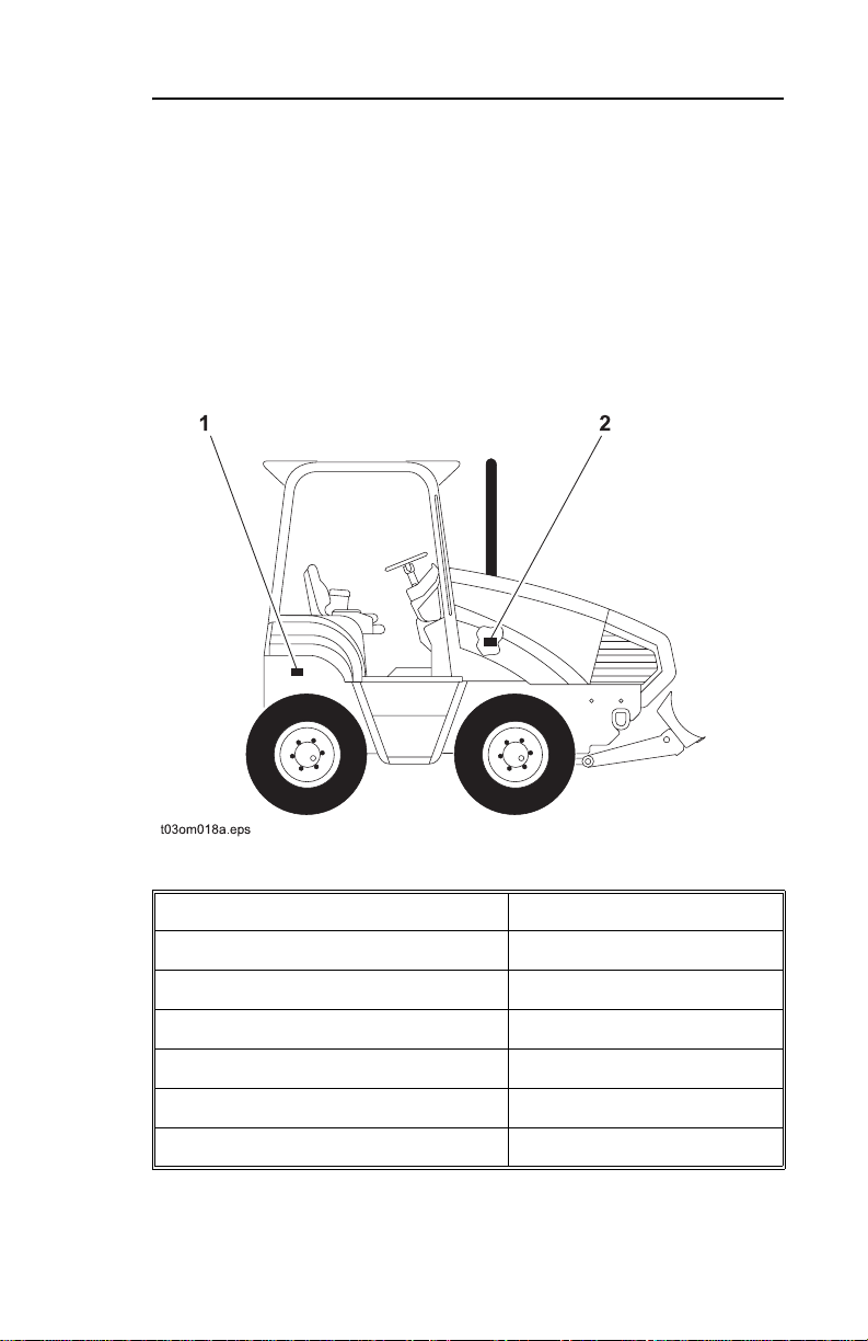
Record serial numbers and date of purchase in spaces provided.
Tractor (1) and engine serial numbers (2) are located as shown.
Date of Manufacture:
Date of Purchase:
Tractor Serial Number:
Front Attachment Serial Number:
Rear Attachment Serial Number:
Trailer Serial Number:
Engine Serial Number:
Page 2

RT115 Tier 3- SUPPORT
SUPPORT PROCEDURE
SUPPORT PROCEDURE
Notify your dealer immediately of any malfunction or failure of
Ditch Witch equipment.
Always give model, serial number, and approximate date of
equipment purchase. This information should be recorded and
placed on file by owner at time of purchase.
Return damaged parts to dealer for inspection and warranty
consideration.
Order genuine Ditch Witch replacement or repair parts from your
authorized Ditch Witch dealer. Use of another manufacturer's
parts may void warranty.
RESOURCES
Publications
Contact your Ditch Witch dealer for publications and videos
covering safety, operation, service, and repair of your equipment.
Ditch Witch Training
For information about on-site, individualized training, contact your
Ditch Witch dealer.
Page 3

RT115 Tier 3 - FOREWORD 3
FOREWORD
This manual is an important part of your equipment. It provides
safety information and operation instructions to help yo u us e an d
maintain your Ditch Witch equipment.
Read this manual before using your equipment. Keep it with the
equipment at all times for future reference. If you sell your
equipment, be sure to give this manual to the new owner.
If you need a replacement copy, contact your Ditch Witch dealer.
If you need assistance in locating a dealer, visit our website at
www.ditchwitch.com or write to the following address:
The Charles Machine Works, Inc.
Attn: Marketing Department
PO Box 66
Perry, OK 73077-0066
USA
The descriptions and specifications in this manual are subject to
change. The Charles Machine Works, Inc. reserves the right to
improve equipment. Some product improvements may have
taken place after this manual was published. For the latest
information on Ditch Witch equipment, see your Ditch Witch
dealer.
Thank you for buying and using Ditch Witch equipment.
Page 4

RT115 Tier 3- FOREWORD
Issue Number 1.1/OP-6/08
Part Number 053-1214
by The Charles Machine Works, Inc.,
RT115 Tier 3
Operator's Manual
Copyright 2007, 2008
Perry, Oklahoma
, Ditch Witch, CMW, AutoCrowd,
Jet Trac, Roto Witch, Subsite, Fluid Miser, Power Pipe,
Super Witch, Pierce Airrow, The Unde rground, Th e Undergrou nd
Authority Worldwide, and Zahn are registered trademarks of
The Charles Machine Works, Inc.
Page 5

RT115 Tier 3 - CONTENTS 5
CONTENTS
SUPPORT . . . . . . . . . . . . . . . . . . . . . . . . . . . . . . . . . . . . . . 1
Serial Number Record . . . . . . . . . . . . . . . . . . . . . . . . . 1
Support Procedure . . . . . . . . . . . . . . . . . . . . . . . . . . . . 2
Resources . . . . . . . . . . . . . . . . . . . . . . . . . . . . . . . . . . 2
FOREWORD . . . . . . . . . . . . . . . . . . . . . . . . . . . . . . . . . . . . 3
OVERVIEW . . . . . . . . . . . . . . . . . . . . . . . . . . . . . . . . . . . . 11
CONTROLS . . . . . . . . . . . . . . . . . . . . . . . . . . . . . . . . . . . 13
Control Console Overview . . . . . . . . . . . . . . . . . . . . . 13
Control Console Descriptions . . . . . . . . . . . . . . . . . . 15
Drive Position Overview . . . . . . . . . . . . . . . . . . . . . . . 25
Drive Position Descriptions. . . . . . . . . . . . . . . . . . . . . 26
Work Position Overview . . . . . . . . . . . . . . . . . . . . . . 31
Work Position Descriptions . . . . . . . . . . . . . . . . . . . . 32
Seat Adjustment Overview. . . . . . . . . . . . . . . . . . . . . 38
Seat Adjustment Descriptions . . . . . . . . . . . . . . . . . . 39
Overhead Console Overview . . . . . . . . . . . . . . . . . . . 41
Overhead Console Descriptions . . . . . . . . . . . . . . . . 42
Page 6

RT115 Tier 3- CONTENTS
SAFETY . . . . . . . . . . . . . . . . . . . . . . . . . . . . . . . . . . . . . . 45
Accessories . . . . . . . . . . . . . . . . . . . . . . . . . . . . . . . . 46
Underground Hazards . . . . . . . . . . . . . . . . . . . . . . . . 46
Emergency Procedures . . . . . . . . . . . . . . . . . . . . . . . 47
Jobsite Classification . . . . . . . . . . . . . . . . . . . . . . . . . 50
Safety Alert Classifications . . . . . . . . . . . . . . . . . . . . 54
Safety Alerts . . . . . . . . . . . . . . . . . . . . . . . . . . . . . . . 55
TRACTOR . . . . . . . . . . . . . . . . . . . . . . . . . . . . . . . . . . . . . 61
Daily Inspection . . . . . . . . . . . . . . . . . . . . . . . . . . . . . 61
Start up . . . . . . . . . . . . . . . . . . . . . . . . . . . . . . . . . . . 62
Operation . . . . . . . . . . . . . . . . . . . . . . . . . . . . . . . . . . 65
Shutdown . . . . . . . . . . . . . . . . . . . . . . . . . . . . . . . . . . 66
TRANSPORTATION . . . . . . . . . . . . . . . . . . . . . . . . . . . . . 67
Lift . . . . . . . . . . . . . . . . . . . . . . . . . . . . . . . . . . . . . . . 67
Tiedown . . . . . . . . . . . . . . . . . . . . . . . . . . . . . . . . . . . 71
Haul . . . . . . . . . . . . . . . . . . . . . . . . . . . . . . . . . . . . . . 76
Tow . . . . . . . . . . . . . . . . . . . . . . . . . . . . . . . . . . . . . . 79
Page 7

RT115 Tier 3 - CONTENTS 7
TRENCHER ATTACHMENT . . . . . . . . . . . . . . . . . . . . . . 81
Trencher Controls Overview . . . . . . . . . . . . . . . . . . . 81
Trencher Control Descriptions . . . . . . . . . . . . . . . . . . 82
Setup . . . . . . . . . . . . . . . . . . . . . . . . . . . . . . . . . . . . . 85
Operation . . . . . . . . . . . . . . . . . . . . . . . . . . . . . . . . . . 87
Operating Tips . . . . . . . . . . . . . . . . . . . . . . . . . . . . . . 92
Optional Equipment . . . . . . . . . . . . . . . . . . . . . . . . . . 93
PLOW ATTACHMENT . . . . . . . . . . . . . . . . . . . . . . . . . . . 95
Plow Controls Overview . . . . . . . . . . . . . . . . . . . . . . 95
Plow Control Descriptions . . . . . . . . . . . . . . . . . . . . . 96
Setup . . . . . . . . . . . . . . . . . . . . . . . . . . . . . . . . . . . . . 99
Operation . . . . . . . . . . . . . . . . . . . . . . . . . . . . . . . . . 102
Operating Tips . . . . . . . . . . . . . . . . . . . . . . . . . . . . . 105
Optional Equipment . . . . . . . . . . . . . . . . . . . . . . . . . 108
REEL WINDER ATTACHMENT . . . . . . . . . . . . . . . . . . . 109
Reel Winder Controls Overview . . . . . . . . . . . . . . . . 109
Reel Winder Control Descriptions . . . . . . . . . . . . . . 110
Setup . . . . . . . . . . . . . . . . . . . . . . . . . . . . . . . . . . . . 111
Operation . . . . . . . . . . . . . . . . . . . . . . . . . . . . . . . . . 112
Page 8

RT115 Tier 3- CONTENTS
SAW ATTACHMENT . . . . . . . . . . . . . . . . . . . . . . . . . . . 115
Saw Controls Overview . . . . . . . . . . . . . . . . . . . . . . 115
Saw Control Descriptions . . . . . . . . . . . . . . . . . . . . 116
Setup . . . . . . . . . . . . . . . . . . . . . . . . . . . . . . . . . . . . 118
Operation . . . . . . . . . . . . . . . . . . . . . . . . . . . . . . . . . 121
Operating Tips . . . . . . . . . . . . . . . . . . . . . . . . . . . . . 126
Optional Equipment . . . . . . . . . . . . . . . . . . . . . . . . . 127
BACKHOE ATTACHMENT . . . . . . . . . . . . . . . . . . . . . . 129
Backhoe Controls Overview . . . . . . . . . . . . . . . . . . 129
Backhoe Control Descriptions . . . . . . . . . . . . . . . . . 130
Setup . . . . . . . . . . . . . . . . . . . . . . . . . . . . . . . . . . . . 137
Operation . . . . . . . . . . . . . . . . . . . . . . . . . . . . . . . . . 138
Stow . . . . . . . . . . . . . . . . . . . . . . . . . . . . . . . . . . . . . 139
DRILLING ATTACHMENT. . . . . . . . . . . . . . . . . . . . . . . . 141
Drilling Attachment Control Description . . . . . . . . . . 142
Prepare Jobsite and Equipment . . . . . . . . . . . . . . . . 143
Drill . . . . . . . . . . . . . . . . . . . . . . . . . . . . . . . . . . . . . . 145
Add Rod . . . . . . . . . . . . . . . . . . . . . . . . . . . . . . . . . . 147
Backream . . . . . . . . . . . . . . . . . . . . . . . . . . . . . . . . . 147
Disassemble Joints. . . . . . . . . . . . . . . . . . . . . . . . . . 148
Optional Equipment . . . . . . . . . . . . . . . . . . . . . . . . . 148
Page 9

RT115 Tier 3 - CONTENTS 9
SERVICE . . . . . . . . . . . . . . . . . . . . . . . . . . . . . . . . . . . . . 149
Approved Coolant. . . . . . . . . . . . . . . . . . . . . . . . . . . 150
Welding Precaution . . . . . . . . . . . . . . . . . . . . . . . . . 151
Overview. . . . . . . . . . . . . . . . . . . . . . . . . . . . . . . . . . 152
10 Hour. . . . . . . . . . . . . . . . . . . . . . . . . . . . . . . . . . . 153
50 Hour. . . . . . . . . . . . . . . . . . . . . . . . . . . . . . . . . . . 175
100 Hour. . . . . . . . . . . . . . . . . . . . . . . . . . . . . . . . . . 179
250 Hour. . . . . . . . . . . . . . . . . . . . . . . . . . . . . . . . . . 183
500 Hour. . . . . . . . . . . . . . . . . . . . . . . . . . . . . . . . . . 188
1000 Hour. . . . . . . . . . . . . . . . . . . . . . . . . . . . . . . . . 194
2000 Hour. . . . . . . . . . . . . . . . . . . . . . . . . . . . . . . . . 199
5000 Hour. . . . . . . . . . . . . . . . . . . . . . . . . . . . . . . . . 201
As Needed . . . . . . . . . . . . . . . . . . . . . . . . . . . . . . . . 203
Tier 3 Service Overview . . . . . . . . . . . . . . . . . . . . . . 212
SPECIFICATIONS . . . . . . . . . . . . . . . . . . . . . . . . . . . . . 221
RT115. . . . . . . . . . . . . . . . . . . . . . . . . . . . . . . . . . . . 221
H910. . . . . . . . . . . . . . . . . . . . . . . . . . . . . . . . . . . . . 226
H911. . . . . . . . . . . . . . . . . . . . . . . . . . . . . . . . . . . . . 228
H932. . . . . . . . . . . . . . . . . . . . . . . . . . . . . . . . . . . . . 230
H952. . . . . . . . . . . . . . . . . . . . . . . . . . . . . . . . . . . . . 232
H1140. . . . . . . . . . . . . . . . . . . . . . . . . . . . . . . . . . . . 236
A720. . . . . . . . . . . . . . . . . . . . . . . . . . . . . . . . . . . . . 238
A920. . . . . . . . . . . . . . . . . . . . . . . . . . . . . . . . . . . . . 240
RC115 . . . . . . . . . . . . . . . . . . . . . . . . . . . . . . . . . . . 242
Page 10

RT115 Tier 3- CONTENTS
Page 11
RT115 Tier 3 - OVERVIEW 11
OVERVIEW
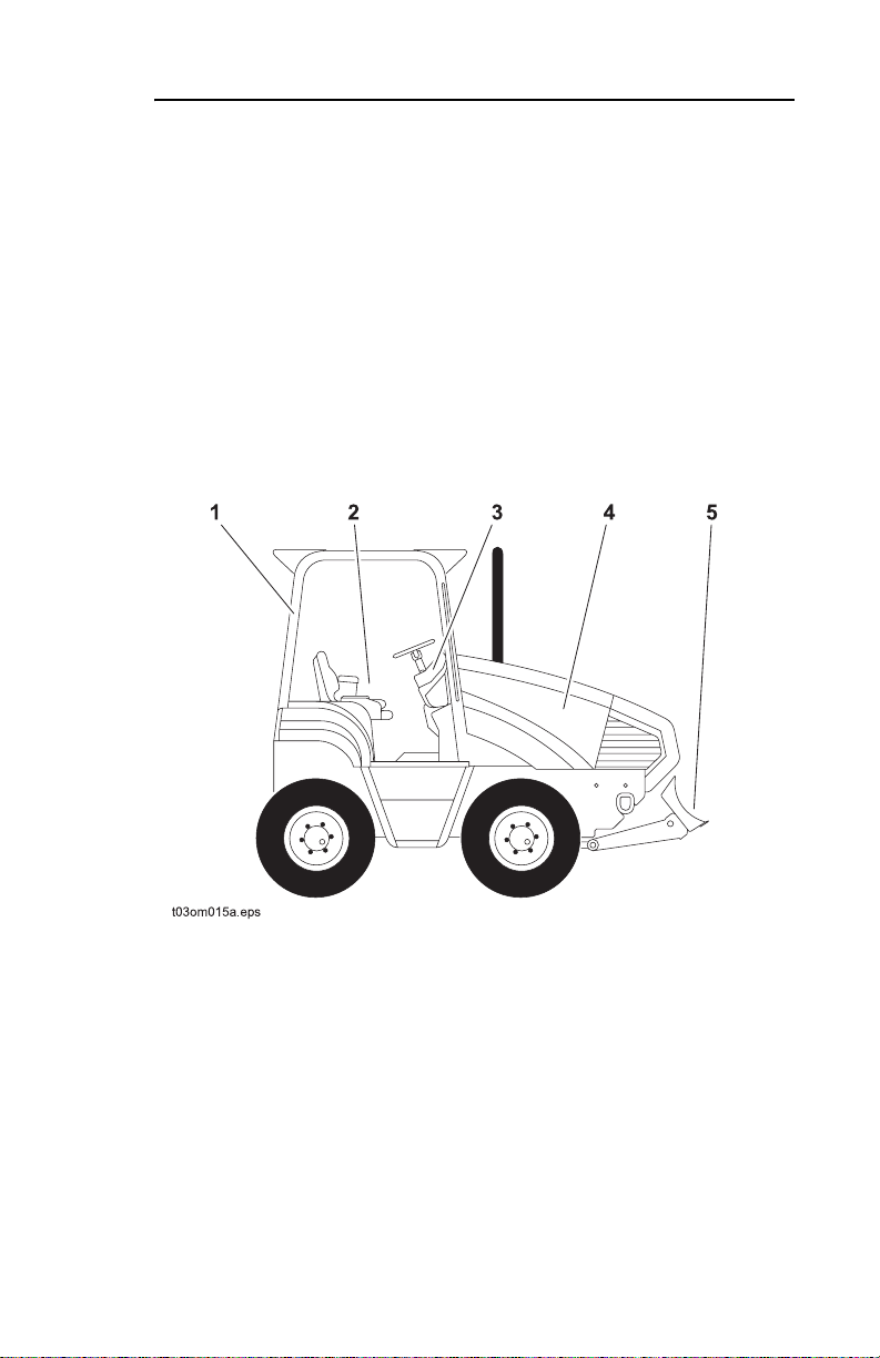
The RT115 Tier 3 tractor is designed for installation of service
lines. It can be fitted with a trencher, vibratory plow, saw,
backhoe or combo plow/trencher attachment. Optional enclosed
cab, work lights, air conditioning, cruise control, rear and
coordinated steering, drilling attachment, and reel carriers are
also available. All rear-mounted attachments feature a new side
plate frame mounting system.
1. Rollover Protective Structure
2. Operator station
3. Control console
4. Engine compartment
5. Backfill blade
Page 12

RT115 Tier 3- OVERVIEW
The H910 trencher for the RT115 Tier 3 tractor cu ts a tren ch with
maximum depth of 94” (2.4 m). Maximum trench width for the
H910 is 24” (610 mm).
The H911 trencher for the RT115 Tier 3 tractor cu ts a tren ch with
maximum depth of 94” (2.4 m). Maximum trench width for the
H911 is 24” (610 mm). Hydraulic traverse on the H911 allows the
trencher to move across the full width of the tractor.
The H932 plow for the RT115 Tier 3 tractor has a cover depth of
36” (915 mm). The H932 is capable of pulling 3” (80 mm) material
and feeding 2” (50 mm) material.
The H952 combo units for the RT115 Tier 3 tract or combin e
trencher and plow. The H952 trenches to a maximum depth of
70” (1.8 m) with trench widths of 6 to 12” (150 to 305 mm). Cover
depth is the same as for the standard plows.
The H1140 for the RT115 Tier 3 tractor is a centerline saw having
a maximum trench depth of 40” (990 mm) with trench widths of
4.5, 6, and 9” (115, 150, and 230 mm) respectively.
Two backhoes are available, the A720 with 91” (2. m) digging
depth, and the A920 with 109” (2.7 m) digging depth. Both
backhoes feature bucket widths of 12 to 24” (305 to 610 mm).
Finally, the RC115 reel carrier is designed to carry 2500 lb (1130
kg) reels. Maximum reel diameter is 84” (2.1 m).
For the purposes of this manual, we define tractor as a selfpropelled wheeled machine, having rear- and/or front-mounted
equipment, primarily designed to produce a trench in a
continuous operation, through motion of the machine; the
attachment can be a digging chain, wheel, plow blade, or similar
item.
Page 13
RT115 Tier 3 - CONTROLS 13
CONTROL CONSOLE OVERVIEW
CONTROLS
CONTROL CONSOLE OVERVIEW
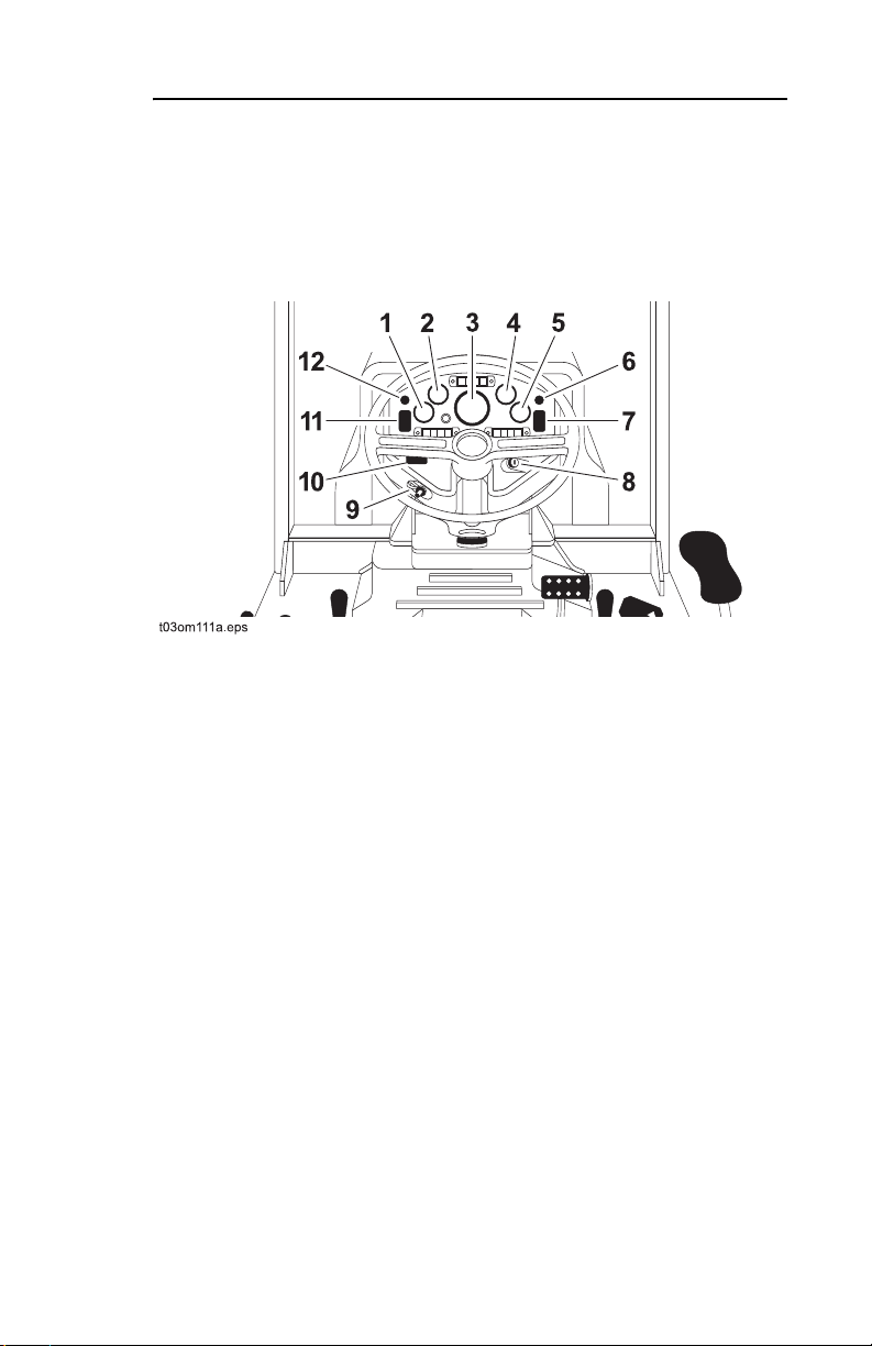
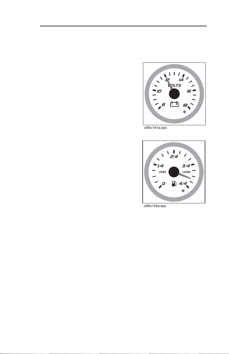
1. Voltmeter
2. Fuel gauge
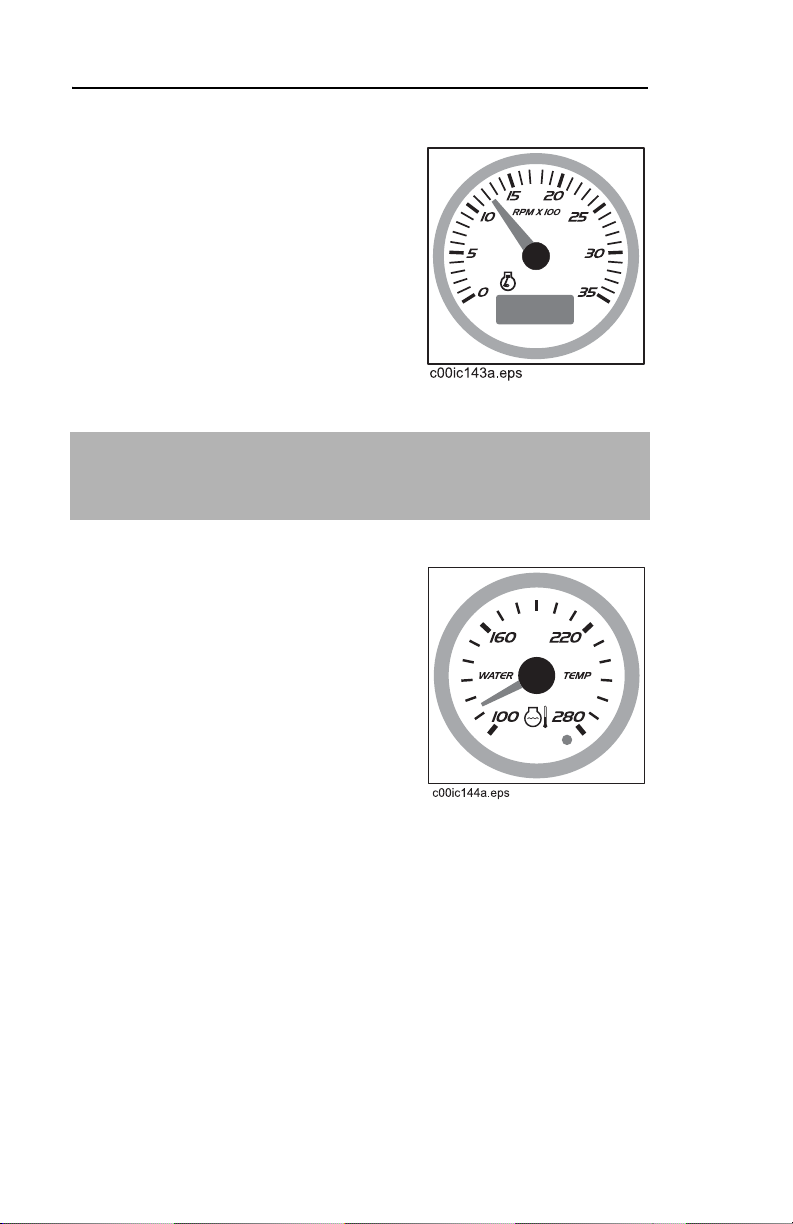
3. Tachometer/
hourmeter/diagnostic
gauge
4. Coolant temperature
gauge
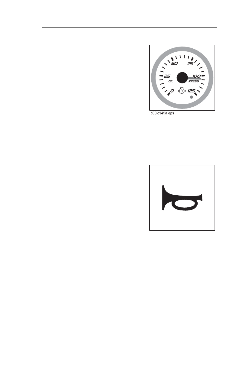
5. Engine oil pressure
gauge
6. Horn
7. Drilling attachment control*
8. Ignition switch
9. Auxiliary power outlet
10. Hydraulic motor control
11. Reel carrier control**
12. Shutdown override control
*See DRILLING ATTACHMENT
for description of this control.
**See PLOW ATTACHMENT for
description of this control.
Page 14
RT115 Tier 3- CONTROLS
CONTROL CONSOLE OVERVIEW
CONTROL CONSOLE OVERVIEW (CONT)
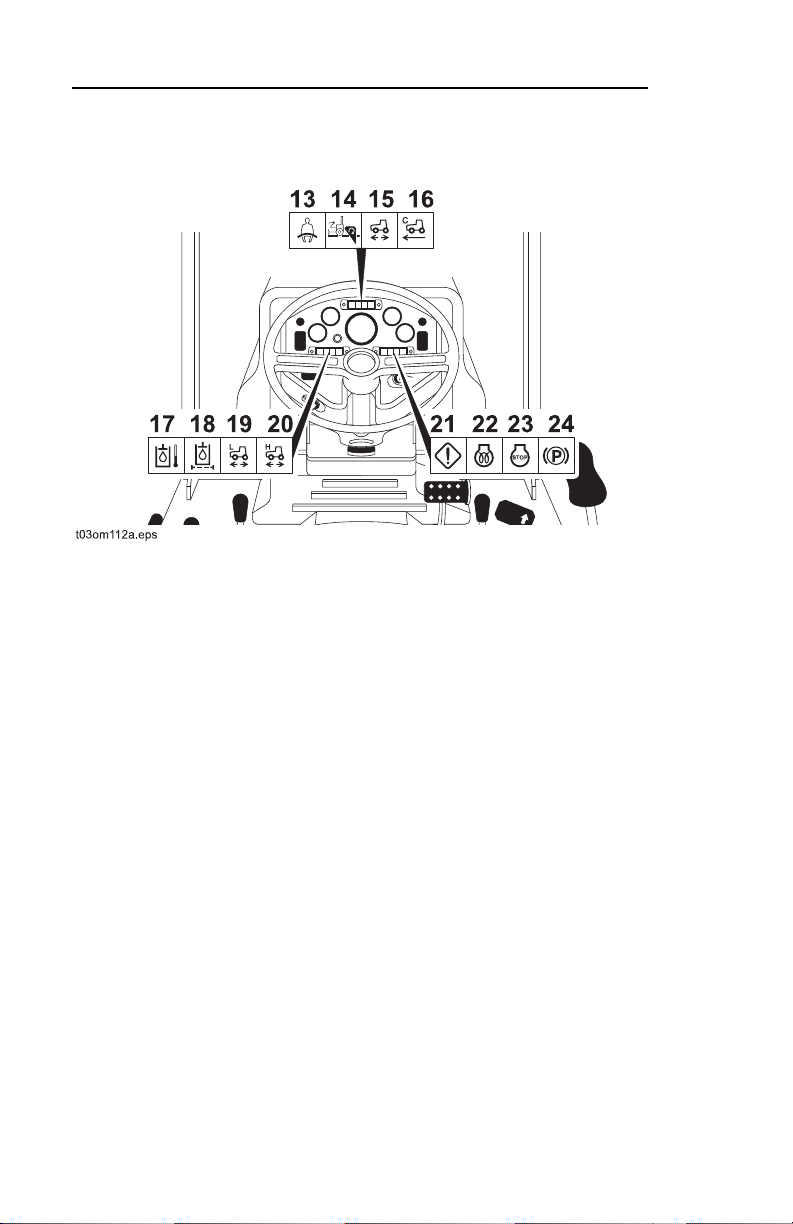
13. Operator presence indicator
14. Attachment speed/direction
indicator
15. Ground drive indicator
16. Cruise control indicator
17. Hydraulic fluid temperature
indicator
18. Hydraulic filter restriction
indicator
19. Low speed indicator
20. High speed indicator
21. Operator alert indicator
22. Cold start wait indicator
23. Engine shutdown
indicator
24. Parking brake indicator
Page 15
RT115 Tier 3 - CONTROLS 15
CONTROL CONSOLE DESCRIPTIONS
CONTROL CONSOLE DESCRIPTIONS
Voltmeter
This gauge displays electrical
system voltage. Reading should
show 12 to 15 volts with engine
running. If not, stop engine and
investigate.
Fuel Gauge
This gauge indicates fuel level in
tank. Use only #2 diesel fuel.
Page 16
RT115 Tier 3- CONTROLS
CONTROL CONSOLE DESCRIPTIONS
Tachometer/Hourmeter/
Diagnostic Gauge
This gauge displays engine rpm,
diagnostic codes, and records
engine operating time.
To view information, press the
selection switch.
IMPORTANT: For more information about the diagnostic
system and trouble codes see "Tier 3 Service Overview" in
SERVICE.
Coolant Temperature Gauge
This gauge displays cooling
system coolant temperature.
Normal coolant temperature is
180°-220° F (82°-104° C).
Alarm will sound if coolant
temperature is high.
If temperature is high:
• Turn off engine and let cool.
• Check cooling system for low
fluid level, seal damage, or
leaks.
Page 17
RT115 Tier 3 - CONTROLS 17
CONTROL CONSOLE DESCRIPTIONS
Engine Oil Pressure Gauge
This gauge shows oil pressure.
Normal operating pressure is
15-50 psi (105-345 kPa).
Alarm will sound if engine oil
pressure is low.
If pressure is low:
• Check oil level.
• If pressure is still low, consult service information from engine
manufacturer.
Horn
Press button to sound horn.
c00ic046a.eps
Page 18
RT115 Tier 3- CONTROLS
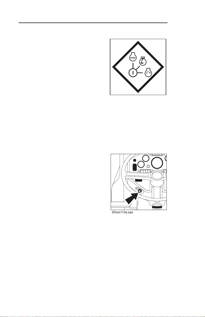
Ignition Switch
This three-position switch starts or
stops engine.
• Insert key and turn all the way
clockwise to start engine.
• Release when engine starts.
CONTROL CONSOLE DESCRIPTIONS
• Key will return to on position.
c00ic012a.eps
• Turn counterclockwise to stop
engine.
If engine does not start on first attempt, check that all interlock
requirements have been met, return switch to stop position, and
try again.
Auxiliary Power Outlet
This outlet can be used to provide
power for other equipment.
Power output is 12 volts, 5 amps.
Page 19
RT115 Tier 3 - CONTROLS 19
CONTROL CONSOLE DESCRIPTIONS
Hydraulic Motor Control
This switch allows operator to
select high or low hydraulic motor
speed.
• Press left to select high
speed. High speed indicator
will light.
• Press right to select low
speed. Low speed indicator
will light.
Shutdown Override Control
This control allows a tempoary
override of engine shutdown.
• Press to delay engine shut
down for 30 seconds after
cycling ignition switch to OFF.
• After 30 seconds, engine will
again shut down unless fault
condition has been cleared on
diagnostic gauge.
IMPORTANT: For more information about the diagnostic
system and trouble codes see "Tier 3 Service Overview" in
SERVICE.
Page 20
RT115 Tier 3- CONTROLS
CONTROL CONSOLE DESCRIPTIONS
Operator Presence Indicator
This indicator lights when
operator is in seat. This indicator
is part of the start interlock
system.
IMPORTANT: All four start interlock indicators must be on to
start engine.
Attachment Speed/Direction
Indicator
This indicator lights when
attachment speed/direction
control is in neutral. This indicator
is part of the start interlock
system.
IMPORTANT: All four start interlock indicators must be on to
start engine.
Page 21
RT115 Tier 3 - CONTROLS 21
CONTROL CONSOLE DESCRIPTIONS
Ground Drive Indicator
Indicator lights when ground drive
control is in neutral.
Cruise Control Indicator
Indicator lights when cruise control
is operating.
Hydraulic Fluid Temperature
Indicator
This indicator lights and alarm
sounds if hydraulic fluid
overheats.
If temperature is high:
• Turn off engine and let cool.
• Check hydraulic fluid level.
• Check front of hydraulic fluid
cooler for debris.
Page 22
RT115 Tier 3- CONTROLS
Hydraulic Filter Restriction
Indicator
This indicator lights when
hydraulic filter is restricted.
Will also light in cold weather. Run
tractor at low engine rpm until
hyraulic fluid warms.
Indicator will turn off after
hydraulic fluid warms.
Change filter when indicator lights.
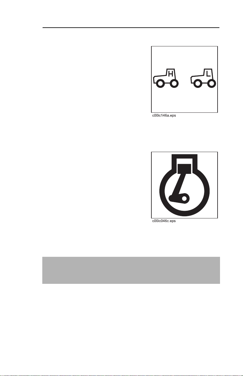
Low Speed Indicator
This indicator lights when
hydraulic motor is in low speed.
CONTROL CONSOLE DESCRIPTIONS
c00ic045a.eps
High Speed Indicator
This indicator lights when
hydraulic motor is in high speed.
Page 23
RT115 Tier 3 - CONTROLS 23
CONTROL CONSOLE DESCRIPTIONS
Operator Alert Indicator
This indicator alerts operator to
Tier 3 engine fault conditions.
• Light flashes when a "warning"
fault is present.
• Light is steady when "engine
shutdown" fault is present.
IMPORTANT: For more information about the diagnostic
system and trouble codes see "Tier 3 Service Overview" in
SERVICE.
Cold Start Wait Indicator
This indicator lights when intake
air pre-heater is operating.
If lamp is on, wait until lamp goes
out before starting engine.
IMPORTANT:
• If ignition key is turned to START before wait lamp goes
out, the system is disabled and must be reset.
• Turn ignition key to OFF, then to RUN to reset.
Page 24

RT115 Tier 3- CONTROLS
Engine Shutdown Indicator
This indicator lights when a critical
engine fault occurs. A fault code
will be stored in the diagnostic
gauge, and the engine will shut
down within 30 seconds.
Parking Brake Indicator
This indicator lights when parking
brake is engaged.
Tractor will not move when
parking brake is engaged.
CONTROL CONSOLE DESCRIPTIONS
c00ic044a.eps
Page 25
RT115 Tier 3 - CONTROLS 25
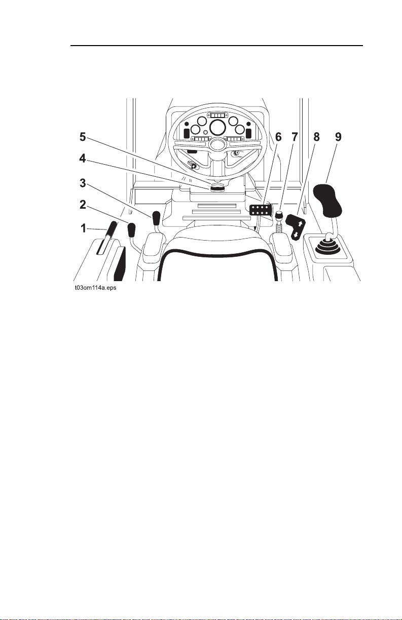
DRIVE POSITION OVERVIEW
DRIVE POSITION OVERVIEW
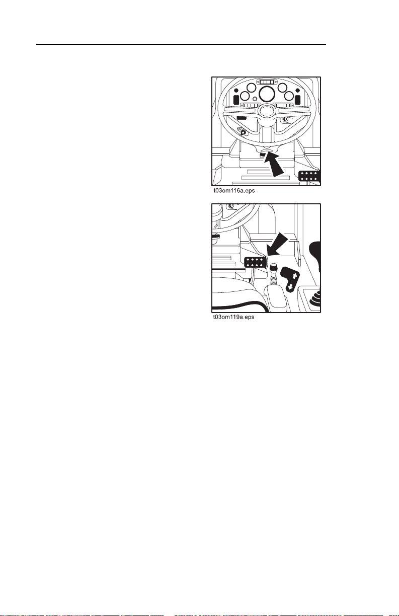
1. Parking brake
2. Gearbox control
3. Attachment speed/
direction control
4. Steering wheel column tilt
control
5. Tilt indicator
6. Service brake
7. Ground drive hand control
8. Ground drive foot control
9. Backfill blade control
Page 26
RT115 Tier 3- CONTROLS
DRIVE POSITION DESCRIPTIONS
DRIVE POSITION DESCRIPTIONS
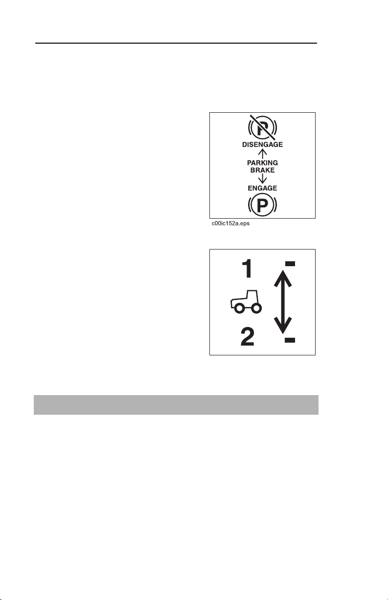
Parking Brake (orange)
This lever controls parking brake.
• Push to disengage.
• Pull to engage.
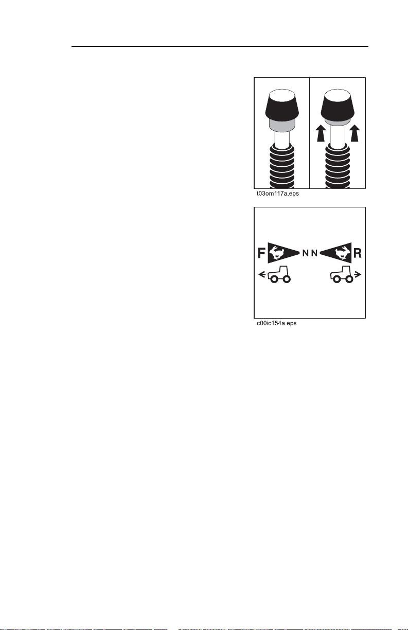
Gearbox Control (yellow)
This lever allows operator to
select high or low gearbox setting.
• Move forward to 1 to select
low.
• Move back to 2 to select high.
c00ic064a.eps
IMPORTANT: Stop tractor before changing gearbox settings.
Page 27
RT115 Tier 3 - CONTROLS 27
DRIVE POSITION DESCRIPTIONS
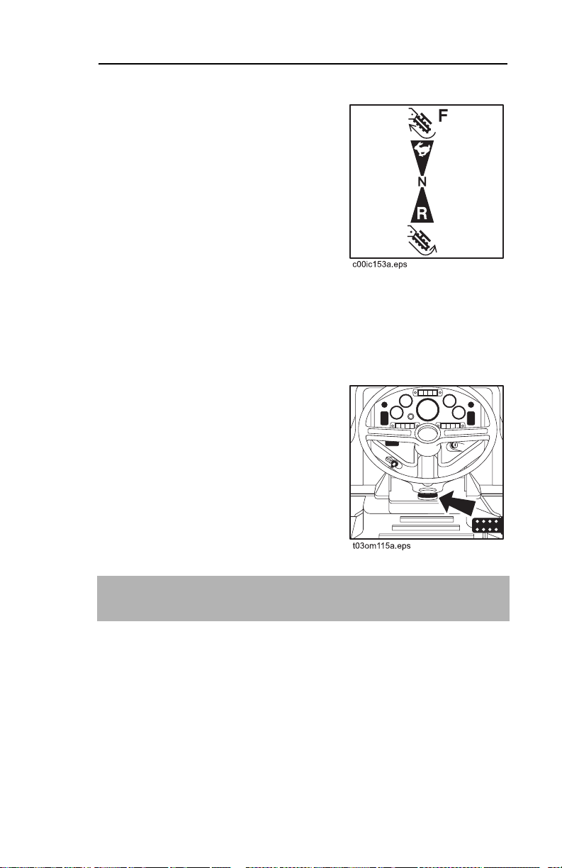
Attachment Speed/Direction
Control (yellow)
This lever controls rear
attachment speed and direction.
• Push to rotate forward or to
start plow vibrator box.
• Pull to rotate backward.
• To go faster in either direction,
move control farther from
neutral position.
• To stop, move control to neutral position.
Steering Wheel Column Tilt
Control
This lever controls the tilt of steering
wheel column.
• Pull to adjust steering wheel
column tilt.
• Release to secure steering
wheel column tilt.
IMPORTANT: Tilt steering wheel column up before pivoting
operator’s seat.
Page 28
RT115 Tier 3- CONTROLS
Tilt Indicator
Indicates tilt away from level.
Service Brake
This pedal stops tractor.
• Press to stop tractor.
• Release to move tractor.
DRIVE POSITION DESCRIPTIONS
Page 29
RT115 Tier 3 - CONTROLS 29
DRIVE POSITION DESCRIPTIONS
Ground Drive Hand Control
(black)
This lever controls unit speed and
direction.
• Pull up on collar to unlock.
• Push forward to go forward.
• Pull back to go backward.
• To go faster in either direction,
move farther from neutral.
• To stop, return to neutral.
Page 30
RT115 Tier 3- CONTROLS
Ground Drive Foot Control
This pedal controls forward or
backward tractor movement.
• Press top to increase forward
speed.
• Press bottom increase
reverse speed.
• Release to reduce speed in
either direction.
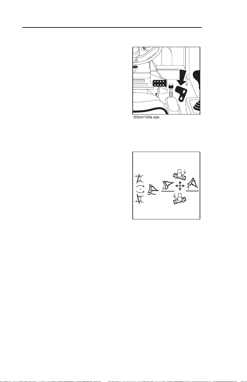
Backfill Blade Control
This lever raises, lowers, tilts and
angles backfill blade.
• Move forward to lower blade.
DRIVE POSITION DESCRIPTIONS
• Move forward to end to float.
• Move backward to raise
blade.
c00ic067a.eps
• Move right to tilt right side of
blade down.
• Move left to tilt left side of blade down.
• Twist left to angle blade left.
• Twist right to angle blade right.
Page 31

RT115 Tier 3 - CONTROLS 31
WORK POSITION OVERVIEW
WORK POSITION OVERVIEW
1. Rear steer adjustment
selector*
2. Steer select control*
3. Frame tilt control*
4. Throttle
5. Diagnostic connector
6. Cruise control selector*
7. Cruise control RPM
selector*
8. Trench Depth Meter*
9. Climate control selector*
10. Air conditioning control*
11. Fan speed control
selector*
12. Auxiliary circuit pressure
gauge
13. Axle lock control
*optional
Page 32

RT115 Tier 3- CONTROLS
WORK POSITION DESCRIPTIONS
WORK POSITION DESCRIPTIONS
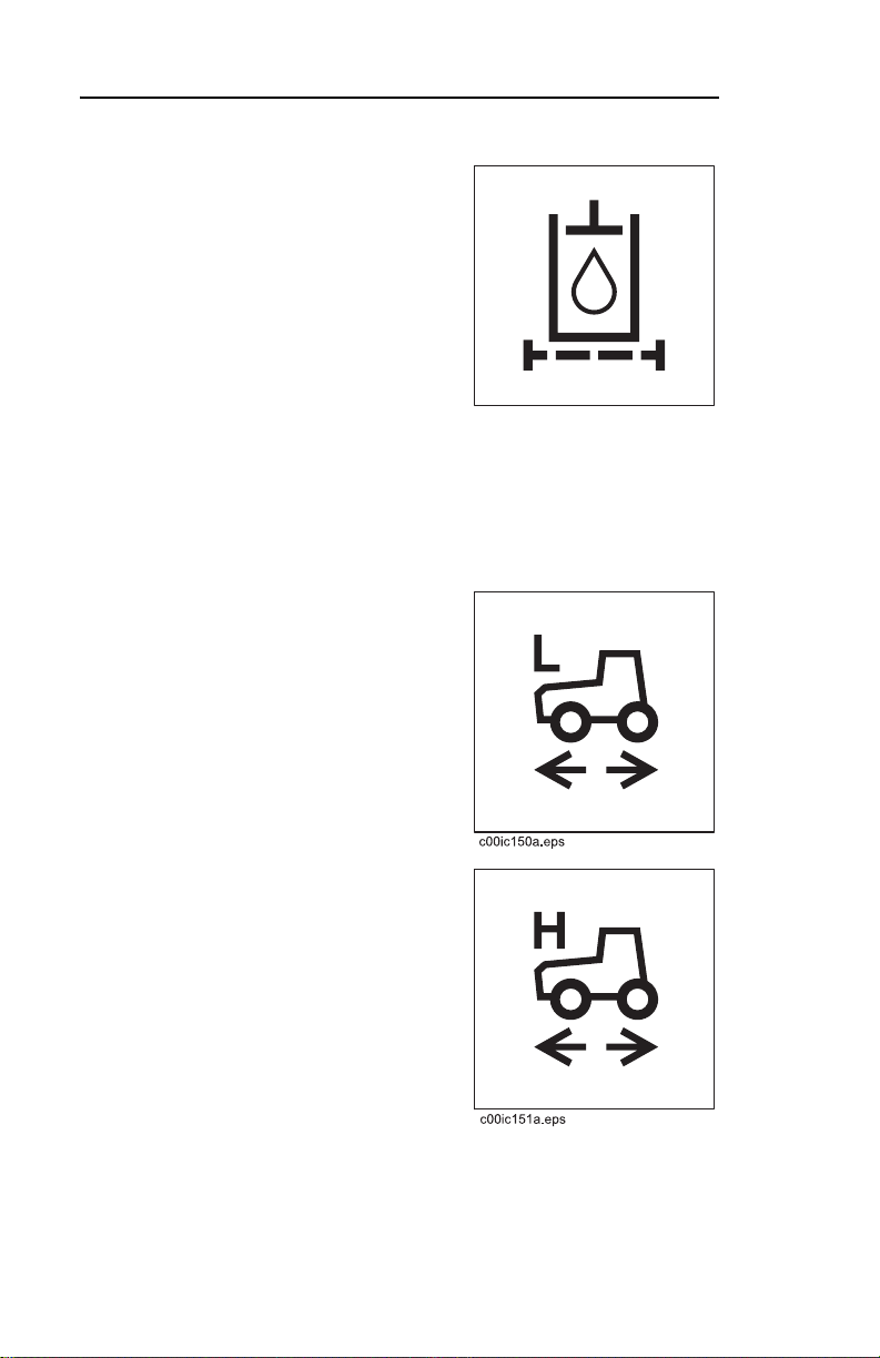
Rear Steer Adjustment Selector
This optional knob turns rear tires
to right or left. Arrow indicates
direction of tires.
• Turn knob counterclockwise
to turn wheels to left.
• Center knob to turn wheels
straight.
c00ic068a.eps
• Turn knob clockwise to turn
wheels to right.
IMPORTANT: Steer select control must be in the center
position for rear steer to work.
Steer Select Control
This optional switch selects
between crab, rear, and
coordinated steering.
• Press top to select crab
steering.
• Move switch to center to
select rear steering.
c00ic069a.eps
• Press bottom to select
coordinated steering.
Page 33

RT115 Tier 3 - CONTROLS 33
WORK POSITION DESCRIPTIONS
Frame Tilt Control
This optional switch tilts frame left
or right.
• Press right side to tilt right.
• Press left side to tilt left.
c00ic070a.eps
Throttle (orange)
This lever controls engine speed.
• Move left to increase speed.
• Move right to reduce speed.
c00ic071a.eps
Page 34

RT115 Tier 3- CONTROLS
WORK POSITION DESCRIPTIONS
Diagnostic Connector
This connector allows manual
reading of diagnostic codes.
IMPORTANT: For more information about the diagnostic
system and trouble codes see "Tier 3 Service Overview" in
SERVICE.
Cruise Control Selector
This optional switch activates the
cruise control feature.
• Press right to turn on.
• Press left to turn off.
Only select cruise control when:
• Gearbox control is in low.
• Hydraulic motor switch is set
at low.
• Ground drive is in neutral.
c00ic055a.eps
Page 35

RT115 Tier 3 - CONTROLS 35
WORK POSITION DESCRIPTIONS
Cruise Control RPM Selector
This optional control adjusts
engine rpm.
• Turn knob clockwise to
increase engine rpm. This
typically decreases ground
speed.
• Turn knob counterclockwise
c00ic054a.eps
to decrease engine rpm. This
typically increases ground
speed.
Climate Control Selector
This optional knob selects cab air
conditioning or heat temperature.
• Turn knob clockwise to
increase heater temperature.
• Turn knob counterclockwise
to lower air conditioning
temperature.
Page 36

RT115 Tier 3- CONTROLS
Air Conditioning Control
This optional switch activates cab
air conditioning.
• Press top to turn air
conditioning on.
• Press bottom to turn air
conditioning off.
Climate Control Fan Speed
Selector
This optional knob controls fan
speed when air conditioning is on.
• Turn knob clockwise for high
speed.
• Turn knob counterclockwise
for low speed.
WORK POSITION DESCRIPTIONS
Page 37

RT115 Tier 3 - CONTROLS 37
WORK POSITION DESCRIPTIONS
Auxiliary Circuit Pressure
Gauge
This gauge displays auxiliary
system pressure. Maximum
operating pressure is 2500 psi
(172 bar).
Axle Lock Control
This switch locks rear axle.
• Press top to lock axle.
• Press bottom to unlock axle.
c00ic072a.eps
IMPORTANT: After pressing switch to unlock axle, move tractor
6’ (2 m) in reverse to unlock.
Page 38

RT115 Tier 3- CONTROLS
SEAT ADJUSTMENT OVERVIEW
SEAT ADJUSTMENT OVERVIEW
2
t03om014a.eps
1. Seat slide control
2. Armrest adjustment
control
1
4
3. Seat pivot control
4. Seat height adjustment
lock (located on opposite
side)
3
Page 39

RT115 Tier 3 - CONTROLS 39
SEAT ADJUSTMENT DESCRIPTIONS
SEAT ADJUSTMENT DESCRIPTIONS
Seat Slide Control
This control slides operator’s seat forward or back wa rd.
Armrest Adjustment Control
These controls raise and lower armrests.
To adjust:
• Remove knob.
• Adjust armrest to desired position.
• Replace knob.
Seat Pivot Control
This control allows operator's seat to be turned to a range of 0 to
90 degrees.
• Pull to pivot seat to the right into work position.
• Release to lock in position.
• Swing operator’s seat to the left to return to drive position.
IMPORTANT: Drive tractor with operator's seat facing front.
Operate rear attachments with seat pivoted to work position.
Page 40

RT115 Tier 3- CONTROLS
SEAT ADJUSTMENT DESCRIPTIONS
Seat Height Adjustment Lock
This control locks seat height.
• Rotate clockwise to lock seat height.
• Rotate counterclockwise to unlock seat height.
Page 41

RT115 Tier 3 - CONTROLS 41
OVERHEAD CONSOLE OVERVIEW
OVERHEAD CONSOLE OVERVIEW
1. Windshield wiper switch*
2. Warning flasher switch*
3. Light switch*
*optional
Page 42

RT115 Tier 3- CONTROLS
OVERHEAD CONSOLE DESCRIPTIONS
OVERHEAD CONSOLE DESCRIPTIONS
Windshield Wiper Switch
This optional switch controls
windshield wipers.
• Press top to turn on.
• Press top to end to wash
windshield.
• Press bottom to turn off.
Warning Flasher Switch
This optional switch controls
warning flashers.
• Press top to turn on.
• Press bottom to turn off.
Page 43

RT115 Tier 3 - CONTROLS 43
OVERHEAD CONSOLE DESCRIPTIONS
Light Switch
This optional switch controls
lights.
• Press top to turn on.
• Press bottom to turn off.
Page 44

RT115 Tier 3- CONTROLS
OVERHEAD CONSOLE DESCRIPTIONS
Page 45

RT115 Tier 3 - SAFETY 45
SAFETY
Follow these guidelines before operating any jobsite equipment:
• Complete proper training and read operator’s manual before
using equipment.
• Contact your local One-Call (811 in USA) or the One-Call
referral number (888-258-0808 in USA and Canada) to have
underground utilities located before digging. Also contact any
utilities that do not participate in the One-Call service.
• Classify jobsite based on its hazards and use correct tool s
and machinery, safety equipment, and work methods for
jobsite.
• Mark jobsite clearly and keep spectators away.
• Wear personal protective equipment.
• Review jobsite hazards, safety and emergency procedures,
and individual responsibilities with all personnel before work
begins. Safety videos are available from your Ditch Witch
dealer.
• Replace missing or damaged safety shields and safety signs.
• Use equipment carefully. Stop operation and investigate
anything that does not look or feel right.
• Do not operate unit where flammable gas is present.
• Contact your Ditch Witch dealer if you have any question
about operation, maintenance, or equipment use.
Page 46

RT115 Tier 3- SAFETY
ACCESSORIES
ACCESSORIES
Fire Extinguisher
If required, a fire extinguisher should be mounted ne ar the powe r
unit but away from possible points of ignition. The fire
extinguisher should always be classified for both oil and electric
fires. It should meet legal and regulatory requirements.
Lighting Kit
If you need additional light, plug lighting kit into provided outlet.
Contact your Ditch Witch dealer for further information.
UNDERGROUND HAZARDS
Striking underground hazards can cause explosion, electrocution,
fire, and exposure to hazardous materials.
Hazards include:
• Electric lines
• Natural gas lines
• Fiber optic cables
• Water lines
• Sewer lines
• Pipes carrying other chemicals, liquids, or gases
• Storage tanks
Page 47

RT115 Tier 3 - SAFETY 47
EMERGENCY PROCEDURES
EMERGENCY PROCEDURES
Before operating any equipment, review emergency procedures
and check that all safety precautions have been taken.
EMERGENCY SHUTDOWN - Turn ignition switch to stop position
or push remote engine stop button.
Electric Strike Description
When working near electric cables, remember the following:
• Electricity follows all paths to ground, not just path of least
resistance.
• Pipes, hoses, and cables will conduct electricity back to all
equipment.
• Low voltage current can injure or kill. Almost one-third of
work-related electrocutions result from contact with less than
440 volts.
Most electric strikes are not noticeable, but indications of a strike
include:
• power outage
•smoke
• explosion
• popping noises
• arcing electricity
If any of these occur, assume an electric strike has occurred.
Page 48

RT115 Tier 3- SAFETY
EMERGENCY PROCEDURES
If an Electric Line is Damaged
If you suspect an electric line has been damaged and you ar e on
tractor, DO NOT MOVE. Remain on tractor and take the
following actions. The order and degree of action will depend
upon the situation.
• Warn people nearby that an electric strike has occurred.
Instruct them to leave the area and contact utility.
• Raise attachments and drive from immediate area.
• Contact utility company to shut off power.
• Do not return to jobsite or allow anyone into area until given
permission by utility company.
If you suspect an electric line has been damaged and you are off
tractor, DO NOT TOUCH TRACTOR. Take the following actions.
The order and degree of action will depend upon the situation.
• LEAVE AREA.
• Contact utility company to shut off power.
• Do not return to jobsite or allow anyone into area until given
permission by utility company.
Page 49

RT115 Tier 3 - SAFETY 49
EMERGENCY PROCEDURES
If a Gas Line is Damaged
If you suspect a gas line has been damaged, take the following
actions. The order and degree of action will depend on the
situation.
• Immediately shut off engine(s), if this can b e done safe ly and
quickly.
• Remove any ignition source(s), if this can be done safely a nd
quickly.
• Warn others that a gas line has been cu t and that they should
leave the area.
• Leave jobsite as quickly as possible.
• Immediately call your local emergency phone number and
utility company.
• If jobsite is along street, stop traffic from driving near jobsite.
• Do not return to jobsite until given permission by emergency
personnel and utility company.
If a Fiber Optic Cable is Damaged
Do not look into cut ends of fiber optic or unidentified cable.
Vision damage can occur.
If Machine Catches on Fire
Perform emergency shutdown procedure and then take the
following actions. The order and degree of action will depend on
the situation.
• Immediately move battery disconnect switch (if equipped) to
disconnect position.
• If fire is small and fire extinguisher is available, attempt to
extinguish fire.
• If fire cannot be extinguished, leave area as quickly as
possible and contact emergency personnel.
Page 50

RT115 Tier 3- SAFETY
JOBSITE CLASSIFICATION
JOBSITE CLASSIFICATION
Inspecting Jobsite
• Follow U.S. Department of Labor regulations on excavating
and trenching (Part 1926, Subpart P) and other similar
regulations.
• Contact One-Call (888-258-0808) and any utility companies
which do not subscribe to One-Call.
• Inspect jobsite and perimeter for evidence of underground
hazards, such as:
– “Buried utility” notices
– Utility facilities without overhead lines
– Gas or water meters
– Junction boxes
– Drop boxes
– Light poles
– Manhole covers
– Sunken ground
• Have an experienced locating equipment operator sweep
area within 20’ (6 m) to each side oftrench path. Verify
previously marked line and cable locations.
• Mark location of all buried utilities and obstructions.
• Classify jobsite.
Page 51

RT115 Tier 3 - SAFETY 51
JOBSITE CLASSIFICATION
Selecting a Classification
Jobsites are classified according to underground hazards
present.
If working . . . then classify jobsite as . . .
within 10’ (3 m) of a buried
electric
electric line
within 10’ (3 m) of a natural
natural gas
gas line
in sand, granite, or concrete
crystalline silica (quartz) dust
which is capable of producing
crystalline silica (quartz) dust
within 10’ (3 m) of any other
other
hazard
NOTICE: If you have any doubt about jobsite classification, or if
jobsite might contain unmarked hazards, take steps outlined
previously to identify hazards and classify jobsite before working.
Page 52

RT115 Tier 3- SAFETY
JOBSITE CLASSIFICATION
Applying Precautions
Once classified, precautions appropriate for jobsite must be
taken.
Electric Jobsite Precautions
Use one or both of these methods.
• Expose line by careful hand digging or soft excavation.
• Have service shut down while work is in progress. Have
electric company test lines before returning them to service.
Natural Gas Jobsite Precautions
In addition to positioning equipment upwind from gas lines, use
one or both of these methods.
• Expose lines by careful hand digging or soft excavation.
• Have gas shut off while work is in progress. Have gas
company test lines before returning them to service.
Page 53

RT115 Tier 3 - SAFETY 53
JOBSITE CLASSIFICATION
Crystalline Silica (Quartz) Dust Precautions
Follow OSHA or other guidelines for exposure to crystalline silica
when trenching, sawing or drilling through material that might
produce dust containing crystalline silica (quartz).
Other Jobsite Precautions
You may ne e d to us e different met ho ds to safe ly av oid oth er
underground hazards. Talk with those knowledgeable about
hazards present at each site to determine which precautions
should be taken or if job should be attempted.
Page 54

RT115 Tier 3- SAFETY
SAFETY ALERT CLASSIFICATIONS
SAFETY ALERT CLASSIFICATIONS
These classifications and the icons defined on the following
pages work together to alert you to situations which could be
harmful to you, jobsite bystanders or your equip ment. When you
see these words and icons in the book or on the machine,
carefully read and follow all instructions. YOUR SAFETY IS AT
STAKE.
Watch for the three safety alert levels: DANGER, WARNING and
CAUTION. Learn what each level means.
indicates an imminently hazardous situation
which, if not avoided, will result in death or serious injury.
indicates a potentially hazardous situation which,
if not avoided, could result in death or serious injury.
indicates a potentially hazardous situation which,
if not avoided, may result in minor or moderate injury.
Watch for two other words: NOTICE and IMPORTANT.
NOTICE can keep you from doing something that might damage
the machine or someone's property. It can also alert you against
unsafe practices.
IMPORTANT can help you do a better job or make your job
easier in some way.
Page 55

RT115 Tier 3 - SAFETY 55
SAFETY ALERTS
SAFETY ALERTS
Turning shaft will kill you or crush
arm or leg. Stay away.
Electric shock. Contacting electric
lines will cause death or serious injury. Know
location of lines and stay away.
Deadly gases. Lack of oxygen or
presence of gas will cause sickness or death.
Provide ventilation.
Page 56

RT115 Tier 3- SAFETY
SAFETY ALERTS
Jobsite hazards
could cause death or serious injury.
Use correct equipment and work
methods. Use and maintain proper
safety equipment.
Crushing weight
could cause death or serious injury .
Use proper procedures and
equipment or stay away.
Moving parts
could cut off hand or foot. Stay
away.
Fall possible. Riders can fall from machine and be injured or
killed. Only operator is allowed on machine.
Page 57

RT115 Tier 3 - SAFETY 57
SAFETY ALERTS
Explosion possible. Serious injury
or equipment damage could occur. Follow
directions carefully.
Incorrect procedures could result
in death, injury, or property damage. Learn to use
equipment correctly.
Looking into fiber optic cable could
result in permanent vision damage. Do not look
into ends of fiber optic or unidentified cable.
Pressurized fluid
or air could pierce skin and cause
injury or death. Stay away.
Page 58

RT115 Tier 3- SAFETY
could ignite and cause burns. No smoking, no
flame, no spark.
situation. Death or serious injury could result.
Avoid moving vehicles, wear high visibility clothing,
post appropriate warning signs.
fluid could cause serious burns. Allow to cool
before servicing.
SAFETY ALERTS
Fire or explosion possible. Fumes
Moving traffic - hazardous
Hot pressurized cooling system
Improper control function could
cause death or serious injury. If control does not
work as described in instructions, stop machine
and have it serviced.
Page 59

RT115 Tier 3 - SAFETY 59
SAFETY ALERTS
Flying objects may cause injury.
Wear hard hat and safety glasses.
Hot parts may cause burns. Do not
touch until cool.
Exposure to high noise levels may
cause hearing loss. Wear hearing protection.
Fall possible. Slips or trips may
result in injury. Keep area clean.
Battery acid may cause burns.
Avoid contact.
Improper handling or use of
chemicals may result in illness, injury, or
equipment damage. Follow instructions on labels
and in material safety data sheets (MSDS).
Page 60

RT115 Tier 3- SAFETY
SAFETY ALERTS
Page 61

RT115 Tier 3 - TRACTOR 61
DAILY INSPECTION
TRACTOR
DAILY INSPECTION
For safe and efficient use of your machine, do the following
before each day’s work.
• Check general appearance of trac to r an d at tachments. Look
for loose, worn, or damaged parts and fluid leaks.
• Check condition of all wear items such as brake pads and
disc, fan belts and light bulbs. Check condition of attachment
wear items.
• Check fuel level.
• Check that all signs, guards, and shields are in place and
readable.
Service machine according to schedules in SERVICE and in
engine manufacturer’s guide.
Page 62

RT115 Tier 3- TRACTOR
START UP
START UP
Before operating tractor, read engine manufacturer’s startin g and
operating instructions. Follow instructions for new engine
break-in.
Explosion possible. Serious
injury or equipment damage could occur. Follow
directions carefully.
NOTICE: Do not use ether as a starting aid on this engine.
Ether may damage engine and cause explosion.
Runaway possible. Machine
could run over you or others. Learn how to use
all controls. Start and operate only from
operator’s position.
sf1008
sf1027
Incorrect procedures could result
in death, injury, or property damage. Learn to
use equipment correctly.
Page 63

RT115 Tier 3 - TRACTOR 63
START UP
Rollover possible. If machine
rolls over, yo u could be thrown from seat and
killed or crushed. Wear seat belt.
sf1011
NOTICE:
• Read operator’s manual before operating equipment.
Follow instructions carefully. Contact Ditch Witch
dealership for operation information or demonstration.
• Wear hard hat, safety glasses, and other protective
equipment required by job. Do not wear jewelry or
loose clothing that can catch on controls.
1. Fasten and adjust seatbelt.
2. Check that ground drive control and attachment speed/
direction control are in neutral.
3. Move throttle to idle.
4. Check that parking brake is engaged.
Page 64

RT115 Tier 3- TRACTOR
START UP
5. Turn ignition switch to start tractor. Warning alarm will sound.
Indicators will light.
If engine does not crank, check start interlock display. See
CONTROLS for start interlock information. If engine turns but
does not start within 10 seconds, allow starter to cool before
trying to start again.
Improper control function could
cause death or serious injury. If control does not
work as described in instructions, stop machine
and have it serviced.
sf1020
NOTICE:
• If warning alarm does not sound, have machine
serviced.
• Machine will not start if start interlock requirements are
not met. See CONTROLS for start interlock
information.
6. Run engine at half-throttle or less for five minutes before
operating tractor.
During warm-up, check that all controls work properly.
Page 65

RT115 Tier 3 - TRACTOR 65
OPERATION
OPERATION
EMERGENCY SHUTDOWN: Turn ignition switch to STOP.
1. Turn on lights and warning flasher, as needed.
2. Tilt steering wheel column down.
3. Raise backfill blade and all attachments.
4. Release parking brake and verify parking brake indicator is
off.
5. Move gearbox control to 2 (high).
6. Adjust throttle.
7. Move ground drive control to forward or reverse.
Moving traffic – hazardous
situation. Death or serious injury could result.
Avoid moving vehicles, wear high visibility
clothing, post appropriate warning signs.
sf1001
NOTICE:
• Drive carefully in congested areas. Know machin e’s
clearance and turning radius.
• Keep attachments low when operating on slope. Drive
slowly and cautiously.
Page 66

RT115 Tier 3- TRACTOR
SHUTDOWN
SHUTDOWN
1. When job is complete, move ground drive control to neutral.
2. Tilt steering wheel column up.
3. Engage parking brake and verify parking brake indicator is
on.
4. Lower all attachments to ground.
5. Move throttle to idle for 3 minutes to cool.
6. Turn ignition switch to STOP. If leaving machine unattended,
remove key.
7. For maintenance or long-term storage, turn battery
disconnect switch to disconnect position.
NOTICE: To prevent damage to turbocharger, do not shut
down engine at full throttle or under load. Should engine die,
immediately remove load and restart engine.
Page 67

RT115 Tier 3 - TRANSPORTATION 67
LIFT
TRANSPORTATION
LIFT
Lifting Points
Lifting points are identified by lifting
decals. Lifting at any other point is
unsafe and can damage machinery.
Tractor
Before lifting, check SPECIFICATIONS. Use a hoist capable of
supporting equipment’s size and weight. Do not attempt to lift
tractor with attachments installed.
Page 68

RT115 Tier 3- TRANSPORTATION
moves, it could kill or crush you. Use proper
procedures and equipment or stay away.
Centerline Trencher
LIFT
Crushing weight. If load falls or
Before lifting, check SPECIFICATIONS. Use a hoist capable of
supporting equipment’s size and weight.
Page 69

RT115 Tier 3 - TRANSPORTATION 69
LIFT
Traversing Trencher
Before lifting, check SPECIFICATIONS. Use a hoist capable of
supporting equipment’s size and weight.
Plow
t03om080a.eps
Before lifting, check SPECIFICATIONS. Use a hoist capable of
supporting equipment’s size and weight.
Page 70

RT115 Tier 3- TRANSPORTATION
Combo
t03om011h.eps
LIFT
Before lifting, check SPECIFICATIONS. Use a hoist capable of
supporting equipment’s size and weight.
Saw
t03om081a.eps
Before lifting, check SPECIFICATIONS. Use a hoist capable of
supporting equipment’s size and weight.
Page 71

RT115 Tier 3 - TRANSPORTATION 71
TIEDOWN
TIEDOWN
Incorrect procedures could
result in death, injury, or property damage.
Learn to use equipment correctly.
Tiedown Points
Tiedown points are identified by
tiedown decals. Securing unit to trailer
at any other points may be unsafe and
can damage machinery.
Tractor
Attach tiedowns at front and rear tiedow n po int s. Ma ke s ur e
tiedowns are tight before transporting unit.
Page 72

RT115 Tier 3- TRANSPORTATION
TIEDOWN
Centerline Trencher
Lower trencher to trailer and tie down at attachment frame and
through boom.
Traversing Trencher
Lower trencher to trailer and tie down at attachment frame and
through boom.
IMPORTANT: If trencher is equipped with a trench cleaner,
ensure that trench cleaner shoe is fully u p and extra bolt (found
in operator’s manual compartment) is installed in appropriate
hole for additional support.
Page 73

RT115 Tier 3 - TRANSPORTATION 73
TIEDOWN
Plow
t03om084a.eps
Lower plow to trailer and tie down at attachment frame and
vibrator box.
NOTICE: Unsecured plow can swing outside the trailer and
become a traffic hazard. Lower plow and chain to trai ler be fo re
hauling.
Page 74

RT115 Tier 3- TRANSPORTATION
TIEDOWN
Combo
t03om010h.eps
Lower trencher and plow to trailer and tie down at attachment
frame and plow vibrator box.
Page 75

RT115 Tier 3 - TRANSPORTATION 75
TIEDOWN
Saw
t03om085a.eps
Lower saw to trailer and tie down at attachment frame and at
hook on rear of saw.
Reel Carrier
Lower reel carrier to trailer and tie down at attachment arms.
Page 76

RT115 Tier 3- TRANSPORTATION
HAUL
Crushing weight could cause
death or serious injury. Use proper procedures
and equipment or stay away.
NOTICE:
• Read trailer operator’s manual before loading or
transporting your machine. Incorrectly load ed machine can
slip or cause trailer sway.
• Park, load, and unload trailer on a level part of jobsite.
Check that unit and trailer do not exceed size or weight
regulations.
HAUL
Rollover possible. If machine
rolls over, you could be thrown from seat and
killed or crushed. Wear seat belt.
Page 77

RT115 Tier 3 - TRANSPORTATION 77
HAUL
Loading
1. Fasten and adjust seatbelt.
2. Tilt steering wheel column down.
3. Start tractor. See TRACTOR for proper start-up procedures.
4. Raise attachments, but keep them low.
5. Move attachments to center position and check that they are
not in float.
6. Release parking brake and verify parking brake indicator is
off.
7. Move hydraulic motor switch to low.
8. Move gearbox control to 1 (low).
9. Slowly drive tractor onto trailer until tie-down position is
reached.
10. Engage parking brake and verify that parking brake indicator
is on.
11. Lower attachments to trailer bed and turn tractor off. See
TRACTOR for proper shutdown procedures.
12. Chain tractor and attachments to trailer using tie-downs.
NOTICE: Check that unit does not exceed trailer size or weight
regulations.
Page 78

RT115 Tier 3- TRANSPORTATION
HAUL
Unloading
1. Check that parking brake is engaged and verify that parking
brake indicator is on.
2. Check that ground drive control is in neutral.
3. Remove tiedowns.
4. Fasten and adjust seatbelt.
5. Tilt steering wheel column down.
6. Start tractor. See TRACTOR for proper start-up procedures.
Rollover possible. If machine
rolls over, you could be thrown from seat and
killed or crushed. Wear seat belt.
NOTICE: Stability is reduced with attachment in
offset position.
7. Raise attachments, but keep them low and centered.
8. Release parking brake and verify that parking brake indicator
is off.
9. Slowly back tractor off trailer.
Page 79

RT115 Tier 3 - TRANSPORTATION 79
TOW
TOW
Incorrect procedures could
result in death, injury, or property damage.
Learn to use equipment correctly.
Under normal conditions, unit should not be towed. If unit
becomes disabled and towing is necessary:
• Tow at less than 1 mph (1.6 km/h).
• Do not tow for more than 200 yd (180 m).
• Steering will be very difficult.
Page 80

RT115 Tier 3- TRANSPORTATION
TOW
Procedure
1. Engage parking brake.
2. Attach tow line to all available tie-down points facing towing
vehicle.
3. Block front and rear tires to prevent unit from rolling.
4. Activate the tow valve.
• Remove floor plate.
• Turn tow valve
counterclockwise two
complete times.
• Replace floor plate.
NOTICE: Do not turn tow valve more than two times.
5. Fasten seatbelt and adjust seatbelt.
6. Remove blocks.
7. Disengage parking brake.
8. Use service brake to control unit.
9. After towing, turn tow valve clockwise two complete times.
Page 81

RT115 Tier 3 - TRENCHER ATTACHMENT 81
TRENCHER CONTROLS OVERVIEW
TRENCHER ATTACHMENT
TRENCHER CONTROLS OVERVIEW
1. Cruise control selector* 4. Boom lift control
2. Trencher slide control 5. Cruise control RPM control*
3. Trench cleaner lift control* 6. Trench Depth Meter*
*optional
Page 82

RT115 Tier 3- TRENCHER ATTACHMENT
TRENCHER CONTROL DESCRIPTIONS
TRENCHER CONTROL DESCRIPTIONS
Cruise Control Selector
This optional switch activates the
cruise control feature.
• Press right to turn on.
• Press left to turn off.
Only select cruise control when:
c00ic055a.eps
• gearbox control is in low
• hydraulic motor switch is set
at low
• ground drive is in neutral.
Trencher Slide Control
This lever controls trencher slide.
• Push to move trencher to
right.
• Pull to move trencher to left.
c00ic081a.eps
IMPORTANT: If slide sticks, lower trencher to ground, operate
trencher slide until trencher moves slightly, raise trencher, and
slide it to position.
Page 83

RT115 Tier 3 - TRENCHER ATTACHMENT 83
TRENCHER CONTROL DESCRIPTIONS
Trench Cleaner Lift Control
This optional lever raises or
lowers trench cleaner.
• Push to lower
• Pull to raise.
c00ic082a.eps
Boom Lift Control
This lever raises or lowers digging
boom.
• Push to lower.
• Pull to raise.
c00ic083a.eps
Page 84

RT115 Tier 3- TRENCHER ATTACHMENT
Cruise Control RPM Control
This optional control adjusts
engine rpm.
• Turn clockwise to increase
engine rpm. This typically
decreases ground speed
temporarily.
• Turn counterclockwise to
decrease engine rpm. This
typically increases ground
speed temporarily.
Trench Depth Meter
Trench Depth Meter (TDM) is an
optional electronic system for
measuring and recording trench
depth. TDM also displays
productivity and distance while
trenching. Two lines of information
are displayed on the LED screen. If
the system detects error
conditions, diagnostic codes will be
displayed on the second line.
TRENCHER CONTROL DESCRIPTIONS
c00ic054a.eps
IMPORTANT: For more information about TDM see the TDM
Operator Manual (p/n 054-117).
Page 85

RT115 Tier 3 - TRENCHER ATTACHMENT 85
SETUP
SETUP
Crushing weight could cause
death or serious injury. Use proper procedures
and equipment or stay away.
NOTICE: Use attachments or counterweight s to make front and
rear loads balance when all attachments are raised. Contact
your Ditch Witch dealer about counterweighting for your
equipment.
Jobsite hazards
could cause death or serious
injury. Use correct equipment and
work methods. Use and maintain
proper safety equipment.
NOTICE: Comply with all utility notification regulations before
digging or drilling.
Incorrect procedures can result in
death, injury, or property damage. Learn to use
equipment correctly.
Page 86

RT115 Tier 3- TRENCHER ATTACHMENT
SETUP
EMERGENCY SHUTDOWN - Turn ignition switch to STOP.
1. Fasten and adjust seat belt.
2. Start tractor. See TRACTOR start-up procedures.
3. Drive to starting point. Move in line with planned trench. See
TRACTOR for operating procedures.
4. Engage parking brake and verify parking brake indicator is
on.
5. Move gearbox control to 1 (low).
6. Select low hydraulic motor speed.
7. Lower backfill blade.
8. Tilt steering wheel column up.
9. Swivel seat to the work position.
10. Engage axle lock.
11. Lower boom to just above ground.
12. Check that attachment speed/direction control is in neutral.
13. Check that boom is in line with planned trench.
Page 87

RT115 Tier 3 - TRENCHER ATTACHMENT 87
OPERATION
OPERATION
Jobsite hazards could cause
death or serious injury. Use correct equipment
and work methods. Use and maintain proper
safety equipment.
NOTICE: Cutting or drilling concrete containing sand or rock
containing quartz may result in exposure to silica dust. Use
respirator, water spray or other means to control dust. Silica
dust can cause lung disease and is known to the State of
California to cause cancer.
Electrical shock. Contacting
electrical lines will cause death or serious injury.
Know location of lines and stay away.
NOTICE: Cutting high voltage cable can cause electrocution.
Expose lines by hand before digging.
Incorrect procedures could result
in death, injury, or property damage. Learn to
use equipment correctly.
NOTICE:
• Comply with all utility notification regulations before digging
or drilling.
• Notify companies that do not subscribe to One-Call.
Page 88

RT115 Tier 3- TRENCHER ATTACHMENT
Flying objects thrown by
machine may strike people. Wear hard hat and
safety glasses.
Moving digging teeth will cause
death or serious injury. Stay away.
NOTICE:
• Ensure parking brake is engaged and parking brake
indicator is on.
• Machine might jerk when digging starts. Allow 3’ (1 m)
between digging teeth and obstacle.
OPERATION
• Keep everyone at least 6’ (2 m) from machine, attachme nts,
and their range of movement.
EMERGENCY SHUTDOWN - Turn ignition switch to STOP.
1. If necessary, adjust throttle to low idle.
2. Move attachment speed/direction control to desired speed.
DIGGING CHAIN WILL MOVE.
3. Lift trench cleaner, if equipped.
4. Increase engine speed to full throttle.
5. Slowly lower digging boom to depth.
6. Raise backfill blade.
7. Release parking brake and verify par kin g br ak e ind ica to r is
off.
Page 89

RT115 Tier 3 - TRENCHER ATTACHMENT 89
OPERATION
8. Move ground drive control to desired speed.
9. If using optional trench cleaner, return ground drive control to
neutral when desired trench depth is reached. Raise boom
slightly, then lower trench cleaner completely. This ensures
trench cleaner will lock in place.
NOTICE:
• Do not have trench cleaner in working position when
starting a trench.
• Do not back up with trench cleaner in working
position.
• Do not use trench cleaner in conditions where large
rocks can get between chain and cleaner.
10. Lower boom to trench depth and push ground drive control
forward to trenching speed.
11. When trench is complete, move ground drive control to
neutral.
12. Adjust throttle to low idle.
13. Raise boom.
14. As boom clears top of trench, move attachment speed/
direction control to neutral.
15. Swivel seat to the drive position.
16. Tilt steering wheel column down.
17. Drive a short distance away from work site.
18. Disengage axle lock by driving tractor in reverse 6’ (2 m).
19. Shut down tractor. See TRACTOR for proper shutdown
procedures.
Page 90

RT115 Tier 3- TRENCHER ATTACHMENT
OPERATION
Cruise Control Operation
EMERGENCY SHUTDOWN - Turn ignition switch to STOP.
1. Ensure ground drive control is in neutral.
2. Ensure hydraulic motor switch is in low.
3. Ensure gearbox control is in 1 (low).
4. Ensure cruise control selector is in MANUAL.
5. Ensure that all controls are set as desired.
6. Move cruise control RPM control to arrow at center.
7. Move cruise control selector to AUTO.
8. Following procedures in "Operation," begin trenching to
desired depth.
9. When desired depth is reached, ensure throttle is fully open.
10. Slowly move ground drive control to full forward position.
11. Slowly adjust cruise control rpm control to match digging
conditions. In harder digging conditions, higher cruise control
rpm setting may improve digging performance. In easier
digging conditions, lower cruise control rpm setting may
increase ground drive speed. See "Operating Tips."
12. When finished digging, move ground drive control to neutral.
13. Move cruise control selector to MANUAL.
14. Allow chain to dig itself free before stopping attachment.
Page 91

RT115 Tier 3 - TRENCHER ATTACHMENT 91
OPERATION
Backfilling
1. Position unit at end of trench, several feet from spoils. Aim
tractor at outer edge of spoils.
2. Adjust backfill blade to fit land contour.
3. Move outer edge of spoils toward trench. Take two or more
passes at spoils rather than moving all spoils at once.
4. Repeat on other side of trench, if necessary.
5. Engage float and make final pass over trench.
EMERGENCY SHUTDOWN - Turn ignition switch to STOP.
Page 92

RT115 Tier 3- TRENCHER ATTACHMENT
OPERATING TIPS
OPERATING TIPS
• Avoid using badly worn teeth. When replacing teeth, maintain
original pattern. Use Ditch Witch replacement teeth.
• Operate engine at full throttle when working.
• Sight along center of hood to a stake driven beyond end of
trench line for straight trench.
• Use correct length boom. See your Ditch Witch dealer fo r
more information.
• Do not make sharp turns. Lower boom to full depth when
turning.
• If an object becomes lodged in chain, move attachment
speed/direction control to neutral and raise boom slightly.
Reverse chain direction. If object must be removed manually,
turn engine off and engage parking brake.
• When cutting asphalt, start trench in soil at edge of road and
use shortest possible boom at full depth.
• Always start trenching with ground drive speed set at low. If
soil conditions permit optimum digging at higher ground drive
speed, select high.
• Before operating booms equipped with rock chains, check bits
for free rotation. Tap bits lightly with a hammer and turn by
hand. If bits are stuck, remove and clean packed soil from bit
block.
• Carbide bits are recommended for cutting abrasive material,
such as sandstone or frozen sands, gravels or asphalts.
EMERGENCY SHUTDOWN - Turn ignition switch to STOP.
Page 93

RT115 Tier 3 - TRENCHER ATTACHMENT 93
OPTIONAL EQUIPMENT
OPTIONAL EQUIPMENT
Chain
A variety of chains, teeth, and tooth patterns are available to
provide efficient digging at any jobsite. For more information,
contact your Ditch Witch dealer.
Trench Cleaner
Trench cleaners remove spoils from trench floor. For more
information about trench cleaners, contact your Ditch Witch
dealer.
Trench Depth Meter
Trench Depth Meter (TDM) is an optional electronic system for
measuring and recording trench depth. TDM also displays
productivity and distance while trenching.
IMPORTANT: For more information ab out TDM see the TDM
Operator Manual (p/n 054-117).
Long Auger Extensions
For conditions that require spoils to be moved farther from the
trench, different augers are available. Ask your Ditch Witch
dealer about the auger length best suited to your jobsite.
Page 94

RT115 Tier 3- TRENCHER ATTACHMENT
OPTIONAL EQUIPMENT
Page 95

RT115 Tier 3 - PLOW ATTACHMENT 95
PLOW CONTROLS OVERVIEW
PLOW ATTACHMENT
PLOW CONTROLS OVERVIEW
1. Plow swing control
2. Blade position control
3. Plow lift control
Page 96

RT115 Tier 3- PLOW ATTACHMENT
PLOW CONTROL DESCRIPTIONS
PLOW CONTROL DESCRIPTIONS
Plow Swing Control
This lever controls plow swing.
• Pull to swing left.
• Push to swing right.
• Push to end to float.
ic0177h.eps
NOTICE:
• If soil conditions allow, operate in float position.
• Lower plow into ground before moving plow swing
control to float position.
• Do not raise plow with plow swing contol in float
position.
Blade Position
This lever controls plow blade
position.
• Pull to steer right.
• Push to steer left.
ic0178h.eps
Page 97

RT115 Tier 3 - PLOW ATTACHMENT 97
PLOW CONTROL DESCRIPTIONS
Plow Lift Control
This lever controls plow lift.
• Pull to raise plow.
• Push to lower plow.
• Push to end to float.
NOTICE:
• If soil conditions allow, operate in float position.
• Lower plow into ground before moving plow swing
control to float position.
• Do not raise plow with plow swing contol in float
position.
Plow Stow Lock
This lever locks or unlocks plow.
• Lift plow and pull lever to
release.
t03om102a.eps
Page 98

RT115 Tier 3- PLOW ATTACHMENT
PLOW CONTROL DESCRIPTIONS
Reel Carrier Control
This optional switch controls reel
carrier.
• Press top to raise.
• Press bottom to lower.
c00ic040a.eps
NOTICE: Operate reel carrier in the lowest position possible for
improved stability and visibility. See SPECIFICATIONS for
counterweight requirements.
Page 99

RT115 Tier 3 - PLOW ATTACHMENT 99
SETUP
SETUP
Crushing weight could cause
death or serious injury. Use proper procedures
and equipment or stay away.
NOTICE:
• Plow will swing freely in float.
• Keep everyone at least 6’ (2 m) from machine,
attachments, and their range of movement.
Jobsite hazards
could cause death or serious
injury. Use correct equipment and
work methods. Use and maintain
proper safety equipment.
NOTICE: Comply with all utility notification regulations before
digging or drilling.
Incorrect procedures could result
in death, injury, or property damage. Learn to
use equipment correctly.
NOTICE:
• Use attachments or counterweights to make front and rear
loads balance when all attachments are raised. Con ta ct
your Ditch Witch dealer about counterweighting for your
equipment.
• Do not operate vibrator unless plow is in ground.
Page 100

RT115 Tier 3- PLOW ATTACHMENT
SETUP
EMERGENCY SHUTDOWN - Turn ignition switch to STOP.
1. Fasten and adjust seat belt.
2. Start tractor. See TRACTOR for start-u p pr oc ed ur e s .
3. Drive to starting point. Move in line with planned trench. See
TRACTOR for operating procedures.
4. Engage parking brake and verify parking brake indicator is
on.
5. Lower backfill blade.
6. Lower plow to starting point of trench.
IMPORTANT: Plow blade will go into ground without
starting a trench, but using one allows for full-depth
starting.
7. Turn ignition switch to STOP.
 Loading...