

Page 1

P80/PP25
Operator’s
Manual
CMW
®
Issue 1.1
053-2296
Page 2

P80/PP25 Operator’s Manual Overview - 1
Overview
Chapter Contents
Serial Number Location . . . . . . . . . . . . . . . . . . . . . . 2
Intended Use . . . . . . . . . . . . . . . . . . . . . . . . . . . . . . . 5
Equipment Modification . . . . . . . . . . . . . . . . . . . . . . 5
Unit Components . . . . . . . . . . . . . . . . . . . . . . . . . . . 5
Operator Orientation. . . . . . . . . . . . . . . . . . . . . . . . . 6
About This Manual . . . . . . . . . . . . . . . . . . . . . . . . . . 6
• Bulleted Lists. . . . . . . . . . . . . . . . . . . . . . . . . . . . . . . . . . . . . . . . . . . . . . 6
• Numbered Lists. . . . . . . . . . . . . . . . . . . . . . . . . . . . . . . . . . . . . . . . . . . . 6
CMW
Page 3

Overview - 2 P80/PP25 Operator’s Manual
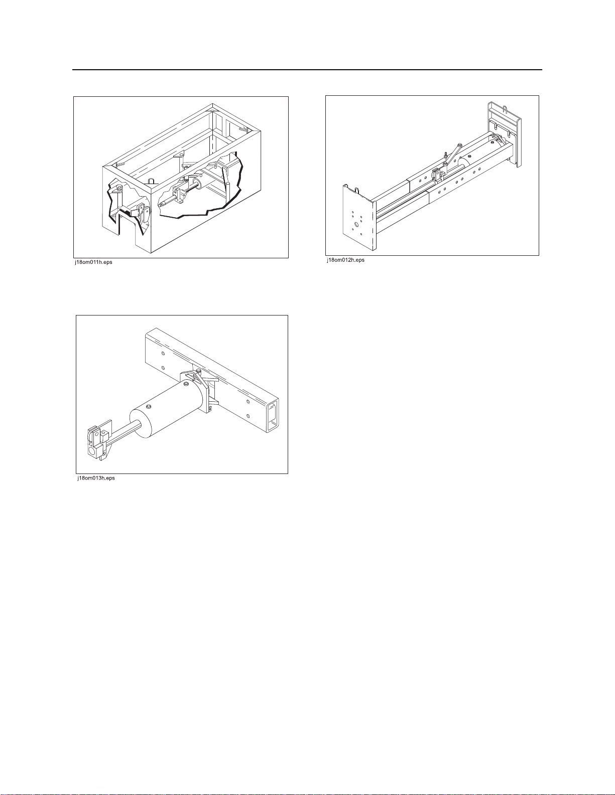
Serial Number Location
Serial Number Location
Record serial numbers and date of purchase in spaces provided.
Date of manufacture
Date of purchase
Rod pusher serial number (shown)
Power pack serial number
Engine serial number
CMW
Page 4

P80/PP25 Operator’s Manual Overview - 3
Unit Components
Unit Components
1. Drill rod
2. Jaw lever
3. Rotation device
4. hydraulic hoses
5. Cylinder
6. Mechanical hydraulic control
(optional)
7. Electric Hydraulic Control
(Optional)
8. Power unit
CMW
Page 5
Overview - 4 P80/PP25 Operator’s Manual
Unit Components
Trench Box Back Brace
T-bar
CMW
Page 6

P80/PP25 Operator’s Manual Overview - 5
Intended Use
Intended Use
The Ditch Witch P80 rod pusher offers a way to bore under sidewalks, roads, or other obstructions without
making open cuts. The rod-through-centerline design produces a true, straight bore. Beacon housings,
heads, and other options make the unit directional. The P80 Rod pusher is compact and easy to use with
either a trench box, back brace, or T-bar set-up configuration.
The Ditch Witch PP25 power pack is designed to provide hydraulic power to a a variety of equipment,
including the P80 rod pusher.
Ditch Witch P80 rod pusher and PP25 power pack should be operated, serviced, and repaired only by
persons familiar with their particular characteristics and acquainted with the relevant safety procedures.
Equipment Modification
This equipment was designed and built in accordance with applicable standards and regulations.
Modification of equipment could mean that it will no longer meet regulations and may not function properly
or in accordance with the operating instructions.
Modification of equipment should only be made by competent personnel possessing knowledge of
applicable standards, regulations, equipment design functionality/requirements and any required
specialized testing.
CMW
Page 7
Overview - 6 P80/PP25 Operator’s Manual
Operator Orientation
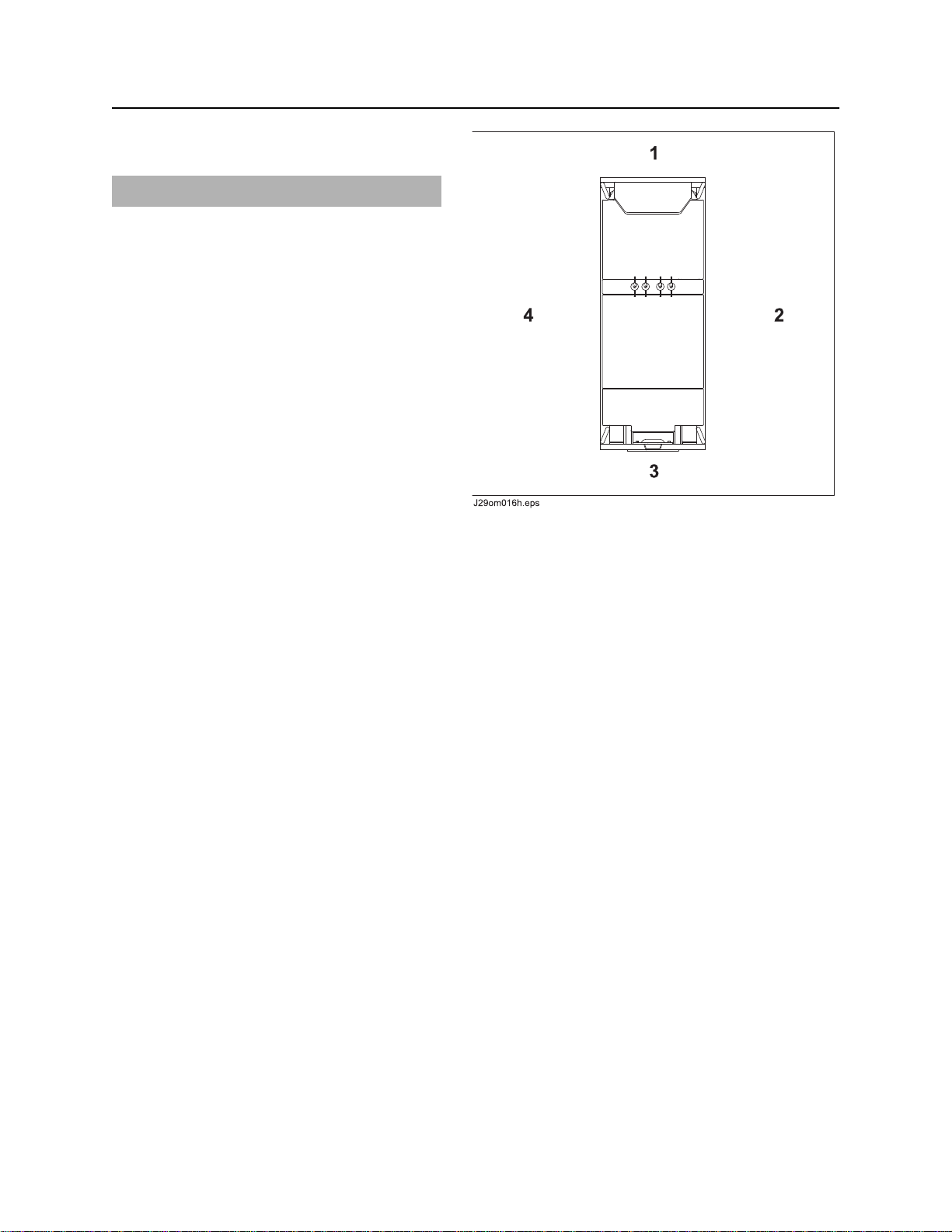
Operator Orientation
IMPORTANT: Top view of unit is shown.
1. Front of unit
2. Right side of unit
3. Rear of unit
4. Left side of unit
About This Manual
This manual contains information for the proper use of this machine. See Operation Overview for basic
operating procedures. Cross references such as “See page 50” will direct you to detailed procedures.
Bulleted Lists
Bulleted lists provide helpful or important information or contain procedures that do not have to be
performed in a specific order.
Numbered Lists
Numbered lists contain illustration callouts or list steps that must be performed in order.
CMW
Page 8

P80/PP25 Operator’s Manual Foreword - 7
Foreword
This manual is an important part of your equipment. It provides safety information and operation
instructions to help you use and maintain your Ditch Witch equipment.
Read this manual before using your equipment. Keep it with the equipment at all times for future reference.
If you sell your equipment, be sure to give this manual to the new owner.
If you need a replacement copy, contact your Ditch Witch dealer. If you need assistance in locating a
dealer, visit our website at www.ditchwitch.com or write to the following address:
The Charles Machine Works, Inc.
Attn: Marketing Department
PO Box 66
Perry, OK 73077-0066
USA
The descriptions and specifications in this manual are subject to change without notice. The Charles
Machine Works, Inc. reserves the right to improve equipment. Some product improvements may have
taken place after this manual was published. For the latest information on Ditch Witch equipment, see your
Ditch Witch dealer.
Thank you for buying and using Ditch Witch equipment.
CMW
Page 9

Foreword - 8 P80/PP25 Operator’s Manual
P80/PP25
Operator’s Manual
Issue number 1.1/OM/02/14
Part number 053-2296
Copyright 2010, 2014
by The Charles Machine Works, Inc.
, Ditch Witch, CMW, AutoCrowd, Jet Trac, Roto Witch, Subsite, Fluid Miser,
Power Pipe, Super Witch, Pierce Airrow, The Underground, The Underground Authority Worldwide, and
Zahn are registered trademarks of The Charles Machine Works, Inc.
CMW
Page 10

P80/PP25 Operator’s Manual Contents - 9
Contents
Overview
machine serial number, information about the type of work this machine is designed
to perform, basic machine components, and how to use this manual
Foreword
part number, revision level, and publication date of this manual, and factory contact
information
Safety
machine safety alerts and emergency procedures
Controls
machine controls, gauges, and indicators and how to use them
Prepare
procedures for inspecting and classifying the jobsite, planning the installation, and
preparing the jobsite for work
Transport
procedures for lifting and hauling
Push Rod
procedures for setting up equipment and pushing rod
1
7
11
21
27
35
41
Complete the Job
procedures for restoring the jobsite and storing equipment
Specifications
machine specifications including weights, measurements, power ratings, and fluid
capacities
Support
the warranty policy for this machine, and procedures for obtaining warranty
consideration and training
Service Record
a record of major service performed on the machine
57
59
65
69
CMW
Page 11

Contents - 10 P80/PP25 Operator’s Manual
CMW
Page 12

P80/PP25 Operator’s Manual Safety - 11
Safety
Chapter Contents
Guidelines . . . . . . . . . . . . . . . . . . . . . . . . . . . . . . . . 12
Safety Alert Classifications . . . . . . . . . . . . . . . . . . 13
Safety Alerts . . . . . . . . . . . . . . . . . . . . . . . . . . . . . . 14
Emergency Procedures . . . . . . . . . . . . . . . . . . . . . 17
• Electric Strike Description. . . . . . . . . . . . . . . . . . . . . . . . . . . . . . . . . . . 17
• If an Electric Line is Damaged . . . . . . . . . . . . . . . . . . . . . . . . . . . . . . . 18
• If a Gas Line is Damaged . . . . . . . . . . . . . . . . . . . . . . . . . . . . . . . . . . . 19
• If a Fiber Optic Cable is Damaged . . . . . . . . . . . . . . . . . . . . . . . . . . . . 19
• If Machine Catches on Fire. . . . . . . . . . . . . . . . . . . . . . . . . . . . . . . . . . 19
CMW
Page 13

Safety - 12 P80/PP25 Operator’s Manual
Guidelines
Guidelines
Follow these guidelines before operating any jobsite equipment:
• Complete proper training and read operator’s manual before using equipment.
• Contact your local One-Call (811 in USA) or the One-Call referral number (888-258-0808 in USA and
Canada) to have underground utilities located before digging. Also contact any utilities that do not
participate in the One-Call service.
• Classify jobsite based on its hazards and use correct tools and machinery, safety equipment, and work
methods for jobsite.
• Mark jobsite clearly and keep spectators away.
• Wear personal protective equipment.
• Review jobsite hazards, safety and emergency procedures, and individual responsibilities with all
personnel before work begins. Safety videos are available from your Ditch Witch dealer.
• Replace missing or damaged safety shields and safety signs.
• Use equipment carefully. Stop operation and investigate anything that does not look or feel right.
• Do not operate unit where flammable gas is present.
• Contact your Ditch Witch dealer if you have any question about operation, maintenance, or equipment
use.
CMW
Page 14

P80/PP25 Operator’s Manual Safety - 13
Safety Alert Classifications
Safety Alert Classifications
These classifications and the icons defined on the following pages work together to alert you to situations
which could be harmful to you, jobsite bystanders or your equipment. When you see these words and
icons in the book or on the machine, carefully read and follow all instructions. YOUR SAFETY IS AT
STAKE.
Watch for the three safety alert levels: DANGER, WARNING and CAUTION. Learn what each level
means.
indicates an imminently hazardous situation which, if not avoided, will result in death or
serious injury.
indicates a potentially hazardous situation which, if not avoided, could result in death or
serious injury.
indicates a potentially hazardous situation which, if not avoided, may result in minor or
moderate injury.
Watch for two other words: NOTICE and IMPORTANT.
NOTICE can keep you from doing something that might damage the machine or someone's property. It
can also alert you against unsafe practices.
IMPORTANT can help you do a better job or make your job easier in some way.
CMW
Page 15
Safety - 14 P80/PP25 Operator’s Manual
Safety Alerts
Safety Alerts
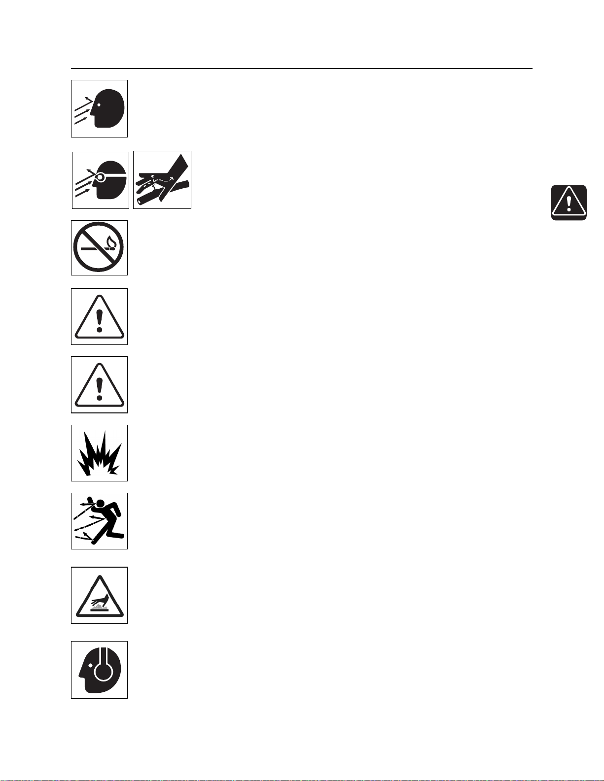
Electric shock. Contacting electric lines will cause death or serious injury.
Know location of lines and stay away.
Deadly gases. Lack of oxygen or presence of gas will cause sickness or
death. Provide ventilation.
Moving tools will kill or injure. Never use wrenches or tools on moving rods
and bursting unit components when unit is operating.
Jobsite hazards could cause death or serious injury. Use
correct equipment and work methods. Use and maintain proper safety
equipment.
Crushing weight could cause death or serious injury. Use
proper procedures and equipment or stay away.
Moving parts on unit could cut off hand or foot. Stay away.
Read operator’s manual. Know how to use all controls before operating
machine. When you see this sign on the machine or in the manual, read it and use
caution. Your safety is at stake.
Improper control function could cause death or serious injury. If control does
not work as described in instructions, stop machine and have it serviced.
CMW
Page 16
P80/PP25 Operator’s Manual Safety - 15
Safety Alerts
Looking into fiber optic cable could result in permanent vision damage. Do
not look into ends of fiber optic or unidentified cable.
Fluid or air pressure could pierce skin and cause injury or
death. Stay away.
Fire or explosion possible. Fumes could ignite and cause burns. No
smoking, no flame, no spark.
Moving traffic - hazardous situation. Death or serious injury could result.
Avoid moving vehicles, wear high visibility clothing, post appropriate warning signs.
Hot pressurized cooling system fluid could cause serious burns. Allow to
cool before servicing.
Explosion possible. Serious injury or equipment damage could occur. Follow
directions carefully.
Flying objects may cause injury. Wear hard hat and safety glasses.
Hot parts may cause burns. Do not touch until cool.
Exposure to high noise levels may cause hearing loss. Wear hearing
protection.
CMW
Page 17
Safety - 16 P80/PP25 Operator’s Manual
Safety Alerts
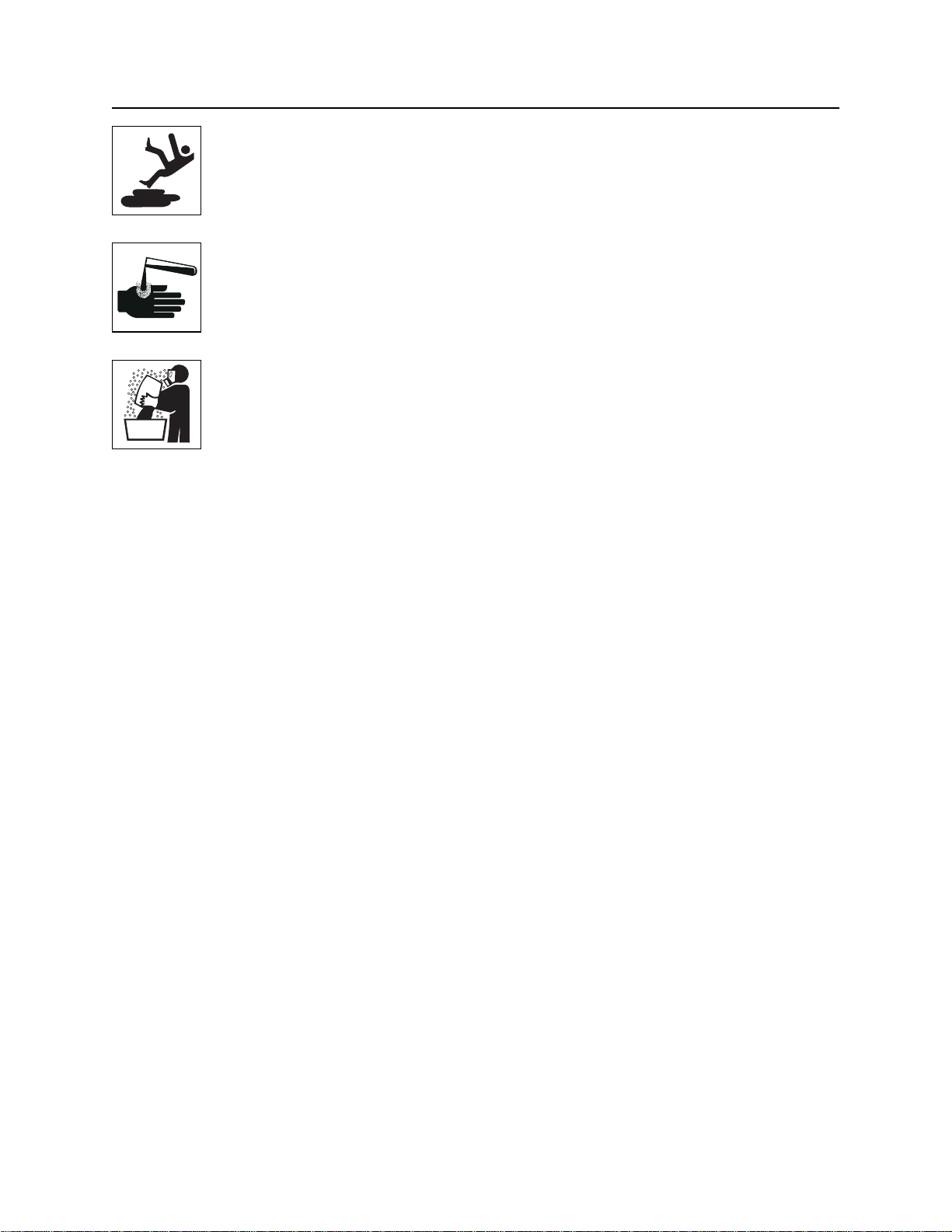
Fall possible. Slips or trips may result in injury. Keep area clean.
Battery acid may cause burns. Avoid contact.
Improper handling or use of chemicals may result in illness, injury, or
equipment damage. Follow instructions on labels and in material safety data sheets
(MSDS).
CMW
Page 18

P80/PP25 Operator’s Manual Safety - 17
Emergency Procedures
Emergency Procedures
Before operating any equipment, review emergency procedures and check that all safety precautions have
been taken.
EMERGENCY SHUTDOWN - Turn ignition switch to stop position or push remote engine stop button.
Electric Strike Description
When working near electric cables, remember the following:
• Electricity follows all paths to ground, not just path of least resistance.
• Pipes, hoses, and cables will conduct electricity back to all equipment.
• Low voltage current can injure or kill. Many work-related electrocutions result from contact with less
than 440 volts.
Most electric strikes are not noticeable, but indications of a strike include:
• power outage
• smoke
• explosion
• popping noises
• arcing electricity
If any of these occur, assume an electric strike has occurred.
CMW
Page 19

Safety - 18 P80/PP25 Operator’s Manual
Emergency Procedures
If an Electric Line is Damaged
If you suspect an electric line has been damaged and you are in pit, DO NOT MOVE and DO NOT
TOUCH ANYTHING. Remain in pit and take the following actions. The order and degree of action will
depend upon the situation.
• Warn people nearby that an electric strike has occurred. Instruct them to leave the area and contact
utility.
• Contact utility company to shut off power.
• Do not leave pit until given permission by utility company.
If you suspect an electric line has been damaged and you are out of pit, DO NOT TOUCH ANYTHING.
Take the following actions. The order and degree of action will depend upon the situation.
• LEAVE AREA. The ground surface may be electrified, so take small steps with feet close together to
reduce the hazard of being shocked from one foot to the other. For more information, contact your
Ditch Witch dealer.
• Contact utility company to shut off power.
• Do not return to jobsite or allow anyone into area until given permission by utility company.
If you suspect an electric line has been damaged and you are on other piece of equipment, DO NOT
MOVE. Remain on truck or trailer and take the following actions. The order and degree of action will
depend on the situation.
• Warn people nearby that an electric strike has occurred. Instruct them to leave the area and contact
utility.
• Contact utility company to shut off power.
• Do not return to area or allow anyone into area until given permission by utility company.
If you suspect an electric line has been damaged and you are off other piece of equipment, DO NOT
TOUCH EQUIPMENT. Take the following actions. The order and degree of action will depend on the
situation.
• LEAVE AREA.
• Contact utility company to shut off power.
• Do not return to area or allow anyone into area until given permission by utility company.
CMW
Page 20

P80/PP25 Operator’s Manual Safety - 19
Emergency Procedures
If a Gas Line is Damaged
If you suspect a gas line has been damaged, take the following actions. The order and degree of action will
depend on the situation.
• Immediately shut off engine(s), if this can be done safely and quickly.
• Remove any ignition source(s), if this can be done safely and quickly.
• Warn others that a gas line has been cut and that they should leave the area.
• Leave jobsite as quickly as possible.
• Immediately call your local emergency phone number and utility company.
• If jobsite is along street, stop traffic from driving near jobsite.
• Do not return to jobsite until given permission by emergency personnel and utility company.
If a Fiber Optic Cable is Damaged
Do not look into cut ends of fiber optic or unidentified cable. Vision damage can occur.
If Machine Catches on Fire
Perform emergency shutdown procedure and then take the following actions. The order and degree of
action will depend on the situation.
• Immediately move battery disconnect switch (if equipped) to disconnect position.
• If fire is small and fire extinguisher is available, attempt to extinguish fire.
• If fire cannot be extinguished, leave area as quickly as possible and contact emergency personnel.
CMW
Page 21

Safety - 20 P80/PP25 Operator’s Manual
Emergency Procedures
CMW
Page 22

P80/PP25 Operator’s Manual Controls - 21
Controls
Chapter Contents
P80 Rod Pusher . . . . . . . . . . . . . . . . . . . . . . . . . . . 22
PP25 Power Pack . . . . . . . . . . . . . . . . . . . . . . . . . . 24
CMW
Page 23

Controls - 22 P80/PP25 Operator’s Manual
P80 Rod Pusher
P80 Rod Pusher
1. Jaw lever
2. Rotation device (optional)
3. Level adjusting screw
Item Description Notes
1. Jaw lever Push lever to move to pull
rod.
Pull lever to push rod.
4. Mechanical hyraulic control valve (optional)
5. Electric hydraulic control (optional)
CMW
Page 24

P80/PP25 Operator’s Manual Controls - 23
P80 Rod Pusher
Item Description Notes
2. Rotation Device This control rotates rod as it is
pushed or pulled.
3. Level Adjusting Screw This control allows the unit to
be adjusted to match grade of
bore.
• Loosen wing nut.
• Adjust unit.
• Tighten wing nut.
4. Mechanical Hydraulic
Control (Optional)
This lever operates the
hydraulic cylinder.
Disengage device to steer rod.
IMPORTANT: Trench box mounted
rod pushers do not have level
adjusting screws. Entire trench box
must be adjusted to set grade of bore.
5. Electric Hydraulic
Control (Optional)
• Engage hydraulic control.
• Move jaw lever to push or
pull rod.
This lever operates the
hydraulic cylinder.
• Engage hydraulic control.
• Move jaw lever to push or
pull rod.
CMW
Page 25

Controls - 24 P80/PP25 Operator’s Manual
PP25
PP25
1. Ignition switch
2. Choke control
3. Fuel gauge
4. Battery voltmeter
5. Hourmeter
Item Description Notes
1. Ignition switch To start engine, insert key and
turn clockwise.
To stop engine, turn key
counterclockwise.
6. Throttle control
7. Battery compartment
8. Case drain hydraulic connector
9. Return hydraulic connector
10. Pressure hydraulic connector
IMPORTANT: If unit won’t start,
ensure all emergency stop switches
are disengaged.
CMW
Page 26

P80/PP25 Operator’s Manual Controls - 25
PP25
Item Description Notes
2. Choke control To close choke valve, pull. Close this valve to enrich air/fuel
mixture and help start cold engine.
Open choke valve after engine runs
for a few seconds.
3. Fuel gauge Displays fuel level in tank.
4. Battery voltmeter Displays system voltage. Should show 12-14V with engine
running during normal operation.
5. Hourmeter Displays engine operating
time.
6. Throttle control To increase engine speed,
push up.
To decrease engine speed,
pull down.
Use these times to schedule service.
CMW
Page 27

Controls - 26 P80/PP25 Operator’s Manual
PP25
Item Description Notes
7. Battery compartment To access battery, turn ring
and remove door.
8. Hydraulic coupler,
case drain
9. Hydraulic coupler,
return
10. Hydraulic coupler,
pressure
To power hydraulic
equipment, connect hydraulic
line to connector.
To disconnect battery, remove
negative (black) cable from battery
post.
NOTICE: Couplers do not connect
under pressure. Do not attempt to
connect hydraulic lines while unit is
operating. Stop PP25 engine before
connecting hydraulic lines.
CMW
Page 28

P80/PP25 Operator’s Manual Prepare - 27
Prepare
Chapter Contents
Gather Information . . . . . . . . . . . . . . . . . . . . . . . . . 28
• Review Job Plan . . . . . . . . . . . . . . . . . . . . . . . . . . . . . . . . . . . . . . . . . . 28
• Notify One-Call Services. . . . . . . . . . . . . . . . . . . . . . . . . . . . . . . . . . . . 28
• Arrange for Traffic Control. . . . . . . . . . . . . . . . . . . . . . . . . . . . . . . . . . . 28
• Plan for Emergency Services . . . . . . . . . . . . . . . . . . . . . . . . . . . . . . . . 28
Inspect Site . . . . . . . . . . . . . . . . . . . . . . . . . . . . . . . 29
• Identify Hazards . . . . . . . . . . . . . . . . . . . . . . . . . . . . . . . . . . . . . . . . . . 29
Classify Jobsite. . . . . . . . . . . . . . . . . . . . . . . . . . . . 30
• Inspect Jobsite . . . . . . . . . . . . . . . . . . . . . . . . . . . . . . . . . . . . . . . . . . . 30
• Select a Classification. . . . . . . . . . . . . . . . . . . . . . . . . . . . . . . . . . . . . . 30
• Apply Precautions. . . . . . . . . . . . . . . . . . . . . . . . . . . . . . . . . . . . . . . . . 31
Check Supplies and Prepare Equipment . . . . . . . 34
• Supplies . . . . . . . . . . . . . . . . . . . . . . . . . . . . . . . . . . . . . . . . . . . . . . . . 34
• Fluid Levels. . . . . . . . . . . . . . . . . . . . . . . . . . . . . . . . . . . . . . . . . . . . . . 34
• Condition and Function. . . . . . . . . . . . . . . . . . . . . . . . . . . . . . . . . . . . . 34
• Accessories. . . . . . . . . . . . . . . . . . . . . . . . . . . . . . . . . . . . . . . . . . . . . . 34
CMW
Page 29

Prepare - 28 P80/PP25 Operator’s Manual
Gather Information
Gather Information
A successful job begins before you dig. The first step in planning is reviewing information already available
about the job and jobsite.
Review Job Plan
Review blueprints or other plans. Check for information about existing or planned structures, elevations, or
proposed work that may be taking place at the same time.
Notify One-Call Services
Contact your local One-Call (811 in USA) or the One-Call referral number (888-258-0808 in USA and
Canada) to have underground utilities located before digging. Also contact any utilities that do not
participate in the One-Call service.
Examine Pullback Material
Ask for a sample of the material you will be pulling back. Check its weight and stiffness. Contact the
manufacturer for bend radius information. Check that you have appropriate devices to attach pullback
material.
Arrange for Traffic Control
If working near a road or other traffic area, contact local authorities about safety procedures and
regulations.
Plan for Emergency Services
Have the telephone numbers for local emergency and medical facilities on hand. Check that you will have
access to a telephone.
CMW
Page 30

P80/PP25 Operator’s Manual Prepare - 29
Inspect Site
Inspect Site
Inspect jobsite before transporting equipment. Check for the following:
• changes in elevation such as hills or other open trenches
• obstacles such as buildings, railroad crossings, or streams
• signs of utilities (See “Inspect Jobsite” on page 30.)
• traffic
• access
• soil type and condition
Identify Hazards
Identify safety hazards and classify jobsite. See “Classify Jobsite” on page 30.
Jobsite hazards could cause death or serious injury. Use
correct equipment and work methods. Use and maintain proper safety
equipment.
NOTICE:
• Wear personal protective equipment including hard hat, safety eye wear, and hearing protection.
• Do not wear jewelry or loose clothing.
• Notify One-Call and companies which do not subscribe to One-Call.
• Comply with all utility notification regulations before digging or drilling.
• Verify location of previously marked underground hazards.
• Mark jobsite clearly and keep spectators away.
Remember, jobsite is classified by hazards in place -- not by line being installed.
CMW
Page 31

Prepare - 30 P80/PP25 Operator’s Manual
Classify Jobsite
Classify Jobsite
Inspect Jobsite
• Follow U.S. Department of Labor regulations on excavating and trenching (Part 1926, Subpart P) and
other similar regulations.
• Contact your local One-Call (811 in USA) or the One-Call referral number (888-258-0808 in USA and
Canada) to have underground utilities located before digging. Also contact any utilities that do not
participate in the One-Call service.
• Inspect jobsite and perimeter for evidence of underground hazards, such as:
– “buried utility” notices
– utility facilities without overhead lines
– gas or water meters
– junction boxes
– drop boxes
– light poles
– manhole covers
– sunken ground
• Have an experienced locating equipment operator sweep area within 20 feet (6 m) to each side of
trench path. Verify previously marked line and cable locations.
• Mark location of all buried utilities and obstructions.
• Classify jobsite.
Select a Classification
Jobsites are classified according to underground hazards present.
If working . . . then classify jobsite as . . .
within 10’ (3 m) of a buried electric line electric
within 10’ (3 m) of a natural gas line natural gas
in sand, granite, or concrete which is capable of producing
crystalline silica (quartz) dust
within 10’ (3 m) of any other hazard other
NOTICE: If you have any doubt about jobsite classification, or if jobsite might contain unmarked
hazards, take steps outlined previously to identify hazards and classify jobsite before working.
crystalline silica (quartz) dust
CMW
Page 32

P80/PP25 Operator’s Manual Prepare - 31
Classify Jobsite
Apply Precautions
Once classified, precautions appropriate for jobsite must be taken.
Electric Jobsite Precautions
Use one or both of these methods.
• Expose line by careful hand digging or soft excavation.
• Have service shut down while work is in progress. Have electric company test lines before returning
them to service.
Natural Gas Jobsite Precautions
In addition to positioning equipment upwind from gas lines, use one or both of these methods.
• Expose lines by careful hand digging or soft excavation.
• Have gas shut off while work is in progress. Have gas company test lines before returning them to
service.
Crystalline Silica (Quartz) Dust Precautions
Follow OSHA or other guidelines for exposure to crystalline silica when trenching, sawing or drilling
through material that might produce dust containing crystalline silica (quartz).
Other Jobsite Precautions
You may need to use different methods to safely avoid other underground hazards. Talk with those
knowledgeable about hazards present at each site to determine which precautions should be taken or if
job should be attempted.
CMW
Page 33

Prepare - 32 P80/PP25 Operator’s Manual
Plan Bore Path
Plan Bore Path
Plan the bore path, from entry to end, before job begins. Locate the entire route of the material to be
installed to ensure a straight path. For complicated bores, consult an engineer. Have jobsite surveyed and
bore path calculated. Expose all crossing or parallel utilities within 18” (500 mm) of the material being
installed.
Mark Bore Path
Mark your planned bore path with flags or paint.
Select Start and End Points
Select one end of the jobsite to use as a starting point. If trench box is used, it can be placed in middle of
bore path and rod can be pushed or pulled both directions, then joined.
Consider the following when selecting a starting point:
• Slope. consider how slope will affect boring unit set-up and bending rod.
• Traffic. Vehicle and pedestrian traffic must be at a safe distance from equipment. Allow at least 10 ft (3
m) buffer zone around equipment.
• Space. Check that starting and eding points allow enough space for gradual rod bending.
• Comfort. Consider shade, wind, fumes, and other site features.
CMW
Page 34

P80/PP25 Operator’s Manual Prepare - 33
Prepare Jobsite
Prepare Jobsite
Jobsite hazards could cause death or serious injury. Use
correct equipment and work methods. Use and maintain proper safety
equipment.
NOTICE:
• Cutting high voltage cable can cause electrocution. Expose lines by hand before digging.
• All vegetation near operator’s station must be removed. Contact with trees, shrubs, or weeds during
electrical strike could result in electrocution.
Dig Installation Pit
Launch rod deep enough to prevent soil mounding. As a general rule, allow one foot of depth for every
inch of rod diameter.
If a trench box is used, depth is limited by soil type according to the US Department of Labor Regulations,
Part 1926, Subpart P. This document is available from the US Government Printing Office, 202-783-3238.
Soil Type Maximum Depth
A 18 ft (5.5 m)
B 10 ft (3.0 m)
C 5 ft (1.7 m)
Installation Pit:
• Must be in line with bore path. For bore to be successful, first rod must be straight.
• Sloped back end aids new product installation. Consider new product bend radius.
• To prevent bending or straining rod, position rod pusher for straight entry.
CMW
Page 35

Prepare - 34 P80/PP25 Operator’s Manual
Check Supplies and Prepare Equipment
Check Supplies and Prepare Equipment
Supplies
• fuel
• keys
• personal protective equipment, such as hard hat and safety glasses
Fluid Levels
• fuel
• hydraulic fluid
• battery charge
• engine oil
Condition and Function
• fan belts
• filters (air, oil, hydraulic)
• pumps and motors
• hoses and valves
• signs, guards, and shields
Accessories
Fire Extinguisher
If required, mount a fire extinguisher near the power unit but away from possible points of ignition. The fire
extinguisher should always be classified for both oil and electric fires. It should meet legal and regulatory
requirements.
CMW
Page 36

P80/PP25 Operator’s Manual Transport - 35
Transport
Chapter Contents
Lift Points and Procedure . . . . . . . . . . . . . . . . . . . 36
• Power Pack . . . . . . . . . . . . . . . . . . . . . . . . . . . . . . . . . . . . . . . . . . . . . 36
• Rod Pusher. . . . . . . . . . . . . . . . . . . . . . . . . . . . . . . . . . . . . . . . . . . . . . 37
• Rod Pusher with T-Bar . . . . . . . . . . . . . . . . . . . . . . . . . . . . . . . . . . . . . 37
• Rod Box . . . . . . . . . . . . . . . . . . . . . . . . . . . . . . . . . . . . . . . . . . . . . . . . 37
• Trench Box . . . . . . . . . . . . . . . . . . . . . . . . . . . . . . . . . . . . . . . . . . . . . . 38
• Trench Box with Extensions . . . . . . . . . . . . . . . . . . . . . . . . . . . . . . . . . 38
• Back Brace . . . . . . . . . . . . . . . . . . . . . . . . . . . . . . . . . . . . . . . . . . . . . . 39
Tie Down Points and Procedure . . . . . . . . . . . . . . 39
CMW
Page 37

Transport - 36 P80/PP25 Operator’s Manual
Lift Points and Procedure
Lift Points and Procedure
Crushing weight. If load falls or moves it could kill or crush you. Use
proper procedures and equipment or stay away.
Lifting points are identified by lifting decals. Lifting at other points is unsafe
and can damage machinery.
Use equipment capable of supporting the size and weight of the unit being
lifted. See “Specifications” on page 99 or measure and weigh equipment
before lifting.
Power Pack
Use equipment capable of supporting the power
pack's size and weight. Use lift chains at lift
points as shown.
CMW
Page 38

P80/PP25 Operator’s Manual Transport - 37
Lift Points and Procedure
Rod Pusher
Use equipment capable of supporting the unit's
size and weight. See “Specifications” on page 99
or measure and weigh equipment before lifting. Lift
rod pusher by connecting chain to lift ring.
Rod Pusher with T-Bar
Attach chain to front lift point.
Rod Box
Use equipment capable of supporting the rod box's
size and weight. Attach chains to lift rings.
CMW
Page 39

Transport - 38 P80/PP25 Operator’s Manual
Lift Points and Procedure
Trench Box
Lift trench box by attaching four chains to lift points
and to a common lift ring. Chains must be:
• at least 80 in (2030 mm) fromlift points to lift
ring,
• of equal length,
• strong enough to bear 10,000 lb (44,500 N)
lifting force.
Maximum allowable lifting force is 20,000 lb
(89,000 N).
Trench Box with Extensions
Lift trench box with extensions by installing
extensions then connecting chains to trench box lift
points, as above.
Do not assemble or disassemble trench box and
extension when trench box is in trench.
CMW
Page 40

P80/PP25 Operator’s Manual Transport - 39
Back Brace
Lift unit with back brace by attaching chain to lift
rings at front and back of back brace.
Lift back brace support by lift ring at top of support.
Tie Down Points and Procedure
Rod pusher, rod box, back brace, and trench box may be carried on any truck or trailer able to transport the
equipment gross weight.
• Install all pins to hold rod pusher in place.
• Use tie-downs to anchor equipment.
CMW
Page 41

Transport - 40 P80/PP25 Operator’s Manual
Tie Down Points and Procedure
CMW
Page 42

P80/PP25 Operator’s Manual Push Rods - 41
Push Rods
Chapter Contents
Setup . . . . . . . . . . . . . . . . . . . . . . . . . . . . . . . . . . . . 42
• Trench Box . . . . . . . . . . . . . . . . . . . . . . . . . . . . . . . . . . . . . . . . . . . . . . 42
• Back Brace . . . . . . . . . . . . . . . . . . . . . . . . . . . . . . . . . . . . . . . . . . . . . . 45
• T-Bar. . . . . . . . . . . . . . . . . . . . . . . . . . . . . . . . . . . . . . . . . . . . . . . . . . . 46
Assemble Strike System . . . . . . . . . . . . . . . . . . . . 48
• Arrange Grid Mats. . . . . . . . . . . . . . . . . . . . . . . . . . . . . . . . . . . . . . . . . 49
• Assemble Bonding Equipment . . . . . . . . . . . . . . . . . . . . . . . . . . . . . . . 50
• Install Control Box and Cables . . . . . . . . . . . . . . . . . . . . . . . . . . . . . . . 51
• Install Strobe Lights. . . . . . . . . . . . . . . . . . . . . . . . . . . . . . . . . . . . . . . . 51
• Connect to Power . . . . . . . . . . . . . . . . . . . . . . . . . . . . . . . . . . . . . . . . . 52
• Test Strike System . . . . . . . . . . . . . . . . . . . . . . . . . . . . . . . . . . . . . . . . 53
. . . . . . . . . . . . . . . . . . . . . . . . . . . . . . . . . . . . . . . . . . .
CMW
Page 43

Push Rods - 42 P80/PP25 Operator’s Manual
Setup
Setup
Read operator’s manual. Know how to use all controls before operating
machine. When you see this sign on the machine or in the manual, read it and use
caution. Your safety is at stake.
Proper set-up and bracing is necessary for efficient rod pushing and pulling. Rod pushers can be used with
three configurations: trench box, back brace, and T-bar. Set-up and bracing procedures depend on
configuration used. Follow set-up instruction for configuration you are using.
Trench Box
Crushing weight could cause death or serious injury. Use
proper procedures and equipment or stay away.
NOTICE: Cave-in possible. Read, understand, and follow US Department of Labor Regulations on
Excavating and Trenching, Part 1926, Subpart P.
1. Dig starting trench at least 3’ (1 m) wide, at least 9’ (3 m) long, and as deep as desired bore. Maximum
trench depth depends on job type. For information on soil typing, read US Department of Labor
Regulations on Excavating and Trenching, Part 1926, Subpart P.
Soil Type Maximum depth
A 18’ (5.5 m)
B 10’ (3.0 m)
C 5’ (1.7 m)
2. Level and compact trench floor.
IMPORTANT: In muddy or unstable soils, place boards across trench floor to support trench box. Level
boards before installing trench box.
3. Dig target trench deep enough to meet bore and long enough to remove rod. Keep spoil on one side of
trench and at least 4’ (1.2 m) away.
4. If trench is deeper than 4’ (1.2 m), install trench box extensions.
5. Fasten chains to lift points, lower trench box into starting trench, and position it.
6. Lower rod pusher into trench.
CMW
Page 44

P80/PP25 Operator’s Manual Push Rods - 43
Setup
7. Install pins, as shown.
8. Slide a rod through cylinder and install pilot head, as
shown.
9. Fasten chain and lift rod pusher in level position. Lower
unit into trench.
10. Backfill and compact soil around trench box. Top 2’
(600 mm) of soil must be well compacted.
CMW
Page 45

Push Rods - 44 P80/PP25 Operator’s Manual
Setup
11. Attach hydraulic control hose to power unit and rod pusher.
12. Set up Electric Strike System. See instructions later in this chapter.
CMW
Page 46

P80/PP25 Operator’s Manual Push Rods - 45
Setup
Back Brace
1. Dig starting trench 18” (460 mm) wide and 72-99” (1830-2500 mm) long.
2. Level and compact trench floors.
3. Dig target trench deep enough to meet bore path and long enough to remove rod.
4. Slide a rod through cylinder and install pilot head.
5. Fasten chain and lift rod pusher in level position. Lower
unit into trench.
6. Attach hydraulic control hoses to power unit hydraulic
manifold. Connect other hoses from hydraulic control
valve block to rod pusher.
7. Align unit with intended bore path.
8. Place a level on push rod at rear of unit. Adjust angle to
match grade of bore.
CMW
Page 47

Push Rods - 46 P80/PP25 Operator’s Manual
Setup
T-Bar
1. Dig T-Bar trench a minimum of 6” (150 mm) wide.
2. Dig rod pusher trench a minimum of 9” (230 mm) wide. Do
not break edges or corners of T-Bar trench.
3. Dig rod trench, as shown. Trench should be slightly longer
than rod being used. Level and compact trench floors.
4. Dig target trench deep enough to meet bore path and long
enough to remove rod.
5. Set T-bar on cylinder and install clip pins.
CMW
Page 48

P80/PP25 Operator’s Manual Push Rods - 47
Setup
6. Slide a rod through cylinder and install pilot head.
7. Fasten chain and lift rod pusher in level position. Lower unit
into trench.
8. Attach hydraulic control hoses to power unit hydraulic
manifold. Connect other hoses from hydraulic control valve
block to rod pusher.
NOTICE: Hydraulic hoses DO NOT connect under
pressure. Stop unit before connecting hydraulic
hoses.
9. Align Unit with intended bore path.
10. Place a level on push rod at rear of unit. Adjust angle to
match grade of bore.
CMW
Page 49

Push Rods - 48 P80/PP25 Operator’s Manual
Assemble Strike System
Assemble Strike System
Anytime rod pusher with trench box is used in an electric jobsite, a trench box with electric strike system
and directional boring system must be properly set up, tested, and used.
In addition to control box, electric strike system includes grid mats, bonding cables, barriers, and protective
boots and gloves meeting the following standards:
• Wear high-top boots with legs of pants tucked completely inside. Boots must meet the electric
hazard protection requirements of ANSI Z-41, 1991, when tested at 14,000 volts.
• Gloves must have 17,000 AC maximum use voltage, according to ASTM specification D120-87.
• If working around higher voltage, use gloves and boots with appropriately higher ratings.
NOTICE: The electric strike system does not prevent electric strikes or detect strikes before they occur.
If alarms are activated, a strike has already occurred and equipment is electrified.
CMW
Page 50

P80/PP25 Operator’s Manual Push Rods - 49
Assemble Strike System
Arrange Grid Mats
A. Bore Path B. Trench Box C. Trailer D. Strike System Control Box E. Power unit
1. Arrange grid mats around trench box.
2. Arrange grid mats between trench box and trailer.
3. Stake grid mats.
4. Place floor grids on rail on trench box floor. Position grids
at end opposite rod pusher and with bonding cables on
same side as welded tab.
CMW
Page 51

Push Rods - 50 P80/PP25 Operator’s Manual
Assemble Strike System
Assemble Bonding Equipment
1. Drive voltage stake into ground at least 6 ft (2 m) from
starting trench.
2. Clip voltage limiter to voltage stake.
3. Connect cable from voltage limiter to back of control
box and lock with 1/4 turn.
4. Connect bonding cables to grid mats.
5. Drive ground rod into soil near grid mats.
6. Move cords and cables under grid mats.
CMW
Page 52

P80/PP25 Operator’s Manual Push Rods - 51
Assemble Strike System
Install Control Box and Cables
1. Attach control box to mounting bracket with wing nuts.
2. Attach current coil cable to top of current coil
assembly
• Attach blue or green connector at (A).
• Attach black connector at (B).
• Attach brown or white connector at (C).
3. Plug current coil into back of control box.
4. Plug power cable into back of control box.
5. Attach bonding cable to top of rod pusher.
6. Connect grids on trench box floor and rod pusher
bonding cable at welded tabs.
7. Connect grid mats by attaching bonding cables to
control box bracket.
Install Strobe Lights
1. Plug other end of power cable into first strobe light.
2. Place light on grid mat near trench box.
3. Plug strobe light bonding cable into grid mat.
4. Plug electric cable into strobe light. Plug other end of
cable into second strob light.
5. Place second strobe light on trailer.
6. Connect strobe light bonding cable to trailer or power
unit.
CMW
Page 53

Push Rods - 52 P80/PP25 Operator’s Manual
Assemble Strike System
Connect to Power
Read operator’s manual. Know how to use all controls before operating
machine. When you see this sign on the machine or in the manual, read it and use
caution. Your safety is at stake.
NOTICES:
• Low main battery power will shut off control box. Backup battery only signals loss of main power.
Restore main power before continuing.
• The electric strike system will work with low backup batteries but might not warn of main battery
system failure.
1. Connect 50 ft (15.3 m) cable to trailer and to control box.
2. Plug power harness with alligator clips to strobe light on trailer.
3. Connect alligator clips to power unit on battery.
CMW
Page 54

P80/PP25 Operator’s Manual Push Rods - 53
Assemble Strike System
Test Strike System
If system fails any part of this test, see “Troubleshooting the Strike System” in MAINTENANCE. Do not
bore until test is completed successfully.
1. Turn power switch on. Light above switch should come on.
2. Check that Lo Main and Lo Backup lights are off.
3. Press test button.
• Horns on boring unit and power unit will sound.
• Strobe lights on both units will flash.
• Voltage and current hazard lights on alarm panel will light.
4. Press reset button.
• Strobes will stop flashing.
• Green system lights will come on.
CMW
Page 55

Push Rods - 54 P80/PP25 Operator’s Manual
Operate
Operate
Crushing weight. If load falls or moves, it could kill or
crush you. Use proper procedures or stay away.
NOTICE: Cave-in possible. Read, understand, and follow US Department of Labor Regulations on
Excavating and Trenching, Part 1926, Subpart P.
Jobsite hazards could cause death or serious injury. Use
correct equipment and work methods. Use and maintain proper safety
equipment.
Fluid or air pressure could pierce skin and cause injury or
death. Stay away.
NOTICE: Escaping pressurized fluid can cause injury or pierce skin and poison. Before disconnecting
lines, turn engine off and operate system controls to relieve pressure. Before using system, check that
all connections are tight and all lines are undamaged. Fluid leaks can be hard to detect. Use a piece of
cardboard or wood, rather than hands, to search for leaks. Wear protective clothing and eye protection.
If you are injured, seek immediate medical attention.
Moving parts on unit could cut off hand or foot. Stay
away.
NOTICE: Stand and work only in
operator’s position (shown large
square).
CMW
Page 56

P80/PP25 Operator’s Manual Push Rods - 55
Operate
Pushing Straight
1. Start power pack.
2. Push pilot head against front wall of trench.
3. Activate hydraulic control.
4. Pull jaw lever back gently. Rod will enter soil.
5. Push jaw lever forward, then gently pull it back again.
NOTICE: Do not clamp jaws on rod threads.
6. As needed, connect new rod, tighten with pipe wrench,
and continue pushing.
Changing Direction
1. Select directional head and attach to beacon housing.
P80 has three directional heads:
• (A) Less aggressive head for tight, clay soil
• (B) Standard head for normal soil
• (C) Aggressive head for soft soil
2. Attach beacon housing assembly to rod.
3. Slide rod through cylinder.
4. Engage rotation control and pull jaw lever back gently.
Rod will enter soil.
5. Pull jaw lever forward, then gently pull it back again. Do
not clamp jaws over threaded joint. Bore first 10 ft (3 m)
and confirm location with detection equipment.
6. Compare location to bore plan. If no steering is needed,
continue to bore, checking beacon readings regularly.
7. To steer:
• Rotate rod until detection equipment clockface indicates direction rod should turn.
• Push rod a short distance without rotation.
• Complete pushing rod with rotation.
• Check beacon location and repeat as necessary.
IMPORTANT: Steering is a skill operators gain with experience. These instructions only cover
basic procedures. For information about specific equipment or jobsites, contact your Ditch
Witch dealer.
8. As needed, connect new rod, tighten with pipe wrench, and continue pushing.
CMW
Page 57

Push Rods - 56 P80/PP25 Operator’s Manual
Operate
Expanding and Pullback
Expanding
A. Rod B. Bell Stop C. Expander D. Clevis
1. When rod reaches target trench, attach bell stop,
expander, and another bell stop. Use clevis to attach
material to drill string.
2. Pull expander back through bore. If bore will be
expanded further, add rod sections behind expander to
keep drill string in bore.
3. When expander is in set-up trench, remove expander
and both expander stops.
4. To expand bore further:
• Remove expander and replace with larger expander.
• Repeat procedure going reverse direction.
• Pull progressively larger expanders followed by rods
until bore is correct diameter for material.
• continue to use strike system when working in electric
jobsite.
Pullback
1. Attach expander stop, expander and clevis to rod end.
Expander should be larger than pullback material.
2. Attach rod pulling grips or threaded rod adapter to
clevis.
3. Pull rod or cable through bore.
Optional Rod Wiper
Before pulling back or expanding, spearate rods in front of unit. Slide rod wiper on rod and reconnect.
CMW
Page 58

P80/PP25 Operator’s Manual Complete the Job - 57
Complete the Job
Chapter Contents
Stow Components . . . . . . . . . . . . . . . . . . . . . . . . . 58
Restore Jobsite . . . . . . . . . . . . . . . . . . . . . . . . . . . 58
Stow Tools. . . . . . . . . . . . . . . . . . . . . . . . . . . . . . . . 58
CMW
Page 59

Complete the Job - 58 P80/PP25 Operator’s Manual
Stow Components
Stow Components
1. Install all covers.
2. Load components onto trailer.
3. Secure all components on trailer.
Restore Jobsite
Fill in installation, bursting and service connection pits.
Stow Tools
Make sure all components, accessories and tools are loaded and properly secured on trailer.
CMW
Page 60

P80/PP25 Operator’s Manual Specifications - 59
P80 w/Trench Box
Specifications
P80 w/Trench Box
Dimensions U.S. Metric
P80 Basic weight 253 lb 115 kg
Trench Box
L, length 108 in 2750 mm
W, width 36 in 920 mm
H1, height 48 in 1220 mm
H2, Height from base to centerline of bore 8.4 in 213 mm
Weight, trench box 930 lb 420 kg
Operating weight w/P80 installed 1240 lb 560 kg
Operating weight w/P80 and 42 4-ft rods 2700 lb 1225 kg
Operational U.S. Metric
Stroke, each cycle 9 in 229 mm
Bore diameter, max. 13 in 325 mm
Hydraulic flow, min to max 5-20 gpm 20-75 L/min
Hydraulic pressure, max 2500 psi 1723.8 bar
Cylinder force at 2500 psi 81,360 lb 362 025 N
CMW
Page 61

Specifications - 60 P80/PP25 Operator’s Manual
P80 w/Trench Box
P80 w/Back Brace
Dimensions U.S. Metric
P80 Basic weight 253 lb 115 kg
Back Brace
L2, Length, min to max 72-100 in 1800-2500 mm
A, Width 17 in 430 mm
H3, Height 18 in 450 mm
D, Height from base to centerline of bore 7.6 in 190 mm
Level adjustment height 6 in 150 mm
Weight, back brace 440 lb 200 kg
Operating weight w/P80 installed 704 lb 320 kg
Operational U.S. Metric
Stroke, each cycle 9 in 229 mm
Bore diameter, max. 13 in 325 mm
Hydraulic flow, min to max 5-20 gpm 20-75 L/min
Hydraulic pressure, max 2500 psi 1723.8 bar
Cylinder force at 2500 psi 81,360 lb 362 025 N
CMW
Page 62

P80/PP25 Operator’s Manual Specifications - 61
P80 w/Trench Box
P80 w/T-Bar
Dimensions U.S. Metric
P80 Basic weight 253 lb 115 kg
T-Bar
A, Cylinder diameter 8 in 200 mm
B, T-Bar width 5.8 in 145 mm
C, T-Bar height 12 in 203 mm
D, Base to cylinder centerline 7.2 in 183 mm
H3, Height without handle 16 in 400 mm
L3, Length, T-bar installed with cylinder retracted 42 in 1050 mm
W2, Width, T-bar 72 in 1800 mm
Push rod diameter 1.75 in 44 mm
Weight of T-bar 204 lb 93 kg
Weight w/P80 installed 462 lb 210 kg
CMW
Page 63

Specifications - 62 P80/PP25 Operator’s Manual
P80 w/Trench Box
Operational U.S. Metric
Stroke, each cycle 9 in 229 mm
Bore diameter, max. 13 in 325 mm
Hydraulic flow, min to max 5-20 gpm 20-75 L/min
Hydraulic pressure, max 2500 psi 172 bar
Cylinder force at 2500 psi 81,360 lb 362 025 N
CMW
Page 64

P80/PP25 Operator’s Manual Specifications - 63
PP25
PP25
Dimensions U.S. Metric
L, length 48.5 in 1.23 m
W, width 27.5 in 700 mm
H, height 30 in 760 mm
Weight, mass (dry weight, without fluids) 685 lb 310 kg
CMW
Page 65

Specifications - 64 P80/PP25 Operator’s Manual
PP25
Power U.S. Metric
Engine: Honda GX690, EPA Phase III
Fuel: gasoline
Cooling medium: air
Cylinders: 2
Displacement
42 in
3
688 cm
Bore 3.03 in 77 mm
Stroke 2.83 in 72 mm
Power
manufacturer’s gross power rating (per SAE J1995) 22.2 hp 16.6 kW
rated speed 3600 rpm 3600 rpm
Hydraulic System U.S. Metric
Pump
Flow capacity @ 3200 rpm 11.7 gpm 44.3 L/min
Maximum pressure 2500 psi 172 bar
Filtration (nominal) 10 micron 10 micron
Fluid Capacities U.S. Metric
Fuel tank 9.5 gal 36 L
Hydraulic reservoir 20 gal 76 L
3
Engine oil, including filter 2.1 qt 1.9 L
Battery
12V, negative ground, SAE cold crank rating @ 0°F (-18°C), 525 amps.
SAE reserve capacity rating, 85 min
Noise Levels
Exterior sound power per ISO 6394 is < or = to 108 dBA per ISO 6394.
Specifications are called out according to SAE recommended practices where indicated. Specifications are
general and subject to change without notice. If exact measurements are required, equipment should be
weighed and measured. Due to selected options, delivered equipment may not necessarily match that
shown.
CMW
Page 66

P80/PP25 Operator’s Manual Support - 65
Procedure
Support
Procedure
Notify your dealer immediately of any malfunction or failure of Ditch Witch® equipment.
Always give model, serial number, and approximate date of your equipment purchase. This information
should be recorded and placed on file by the owner at the time of purchase.
Return damaged parts to dealer for inspection and warranty consideration if in warranty time frame.
Order genuine Ditch Witch replacement or repair parts from your authorized Ditch Witch dealer. Use of
another manufacturer's parts may void warranty consideration.
Resources
Publications
Contact your Ditch Witch dealer for publications and videos covering safety, operation, service, and repair
of your equipment.
Ditch Witch Training
For information about on-site, individualized training, contact your Ditch Witch dealer.
CMW
®
Page 67

Warranty - 66 P80/PP25 Operator’s Manual
Warranty
Ditch Witch® Equipment and Replacement Parts
Limited Warranty Policy
Subject to the limitation and exclusions herein, free replacement parts will be provided at any authorized Ditch Witch dealership for
any Ditch Witch equipment or parts manufactured by The Charles Machine Works, Inc. (CMW) that fail due to a defect in material or
workmanship within one (1) year of first commercial use. Free labor will be provided at any authorized Ditch Witch dealership for
installation of parts under this warranty during the first year following “initial commercial” use of the serial-numbered Ditch Witch
equipment on which it is installed. The customer is responsible for transporting their equipment to an authorized Ditch Witch
dealership for all warranty work.
Exclusions from Product Warranty
• All incidental or consequential damages.
• All defects, damages, or injuries caused by misuse, abuse, improper installation, alteration, neglect, or uses other than those for
which products were intended.
• All defects, damages, or injuries caused by improper training, operation, or servicing of products in a manner inconsistent with
manufacturer’s recommendations.
• All engines and engine accessories (these are covered by original manufacturer’s warranty).
• Tires, belts, and other parts which may be subject to another manufacturer’s warranty (such warranty will be available to
purchaser).
• ALL IMPLIED WARRANTIES NOT EXPRESSLY STATED HEREIN, INCLUDING ANY WARRANTY OF FITNESS FOR A
PARTICULAR PURPOSE AND MERCHANTABILITY.
IF THE PRODUCTS ARE PURCHASED FOR COMMERCIAL PURPOSES, AS DEFINED BY THE UNIFORM COMMERCIAL
CODE, THEN THERE ARE NO WARRANTIES WHICH EXTEND BEYOND THE FACE HEREOF AND THERE ARE NO IMPLIED
WARRANTIES OF ANY KIND WHICH EXTEND TO A COMMERCIAL BUYER. ALL OTHER PROVISIONS OF THIS LIMITED
WARRANTY APPLY INCLUDING THE DUTIES IMPOSED.
Ditch Witch products have been tested to deliver acceptable performance in most conditions. This does not imply they will deliver
acceptable performance in all conditions. Therefore, to assure suitability, products should be operated under anticipated working
conditions prior to purchase.
Defects will be determined by an inspection within thirty (30) days of the date of failure of the product or part by CMW or its authorized
dealer. CMW will provide the location of its inspection facilities or its nearest authorized dealer upon inquiry. CMW reserves the right
to supply remanufactured replacements parts under this warranty as it deems appropriate.
Extended warranties are available upon request from your local Ditch Witch dealer or CMW.
Some states do not allow exclusion or limitation of incidental or consequential damages, so above limitation of exclusion may not
apply. Further, some states do not allow exclusion of or limitation of how long an implied warranty lasts, so the above limitation may
not apply. This limited warranty gives product owner specific legal rights and the product owner may also have other rights which vary
from state to state.
For information regarding this limited warranty, contact CMW’s Product Support department, P.O. Box 66, Perry, OK 73077-0066, or
contact your local Ditch Witch dealer.
First version: 1/91; Latest version: 11/11
CMW
®
Page 68

Page 69

Page 70

P80/PP25 Operator’s Manual Service Record - 69
Service Record
Service Performed Date Hours
CMW
®
Page 71

Service Record - 70 P80/PP25 Operator’s Manual
Service Performed Date Hours
CMW
®
 Loading...