


OnGrade
Operator’s
Manual
CMW
®
Issue 1.0
053-1393

OnGrade Operator’s Manual Overview - 1
Overview
Chapter Contents
Serial Number Location . . . . . . . . . . . . . . . . . . . . . . 2
Intended Use . . . . . . . . . . . . . . . . . . . . . . . . . . . . . . 3
About This Manual . . . . . . . . . . . . . . . . . . . . . . . . . . 3
• Bulleted Lists . . . . . . . . . . . . . . . . . . . . . . . . . . . . . . . . . . . . . . . . . . . . . .3
• Numbered Lists . . . . . . . . . . . . . . . . . . . . . . . . . . . . . . . . . . . . . . . . . . . .3
• “Continued” Indicators . . . . . . . . . . . . . . . . . . . . . . . . . . . . . . . . . . . . . . .3
FCC Statement - Internal Transmitter . . . . . . . . . . . 4
CMW
Overview - 2 OnGrade Operator’s Manual
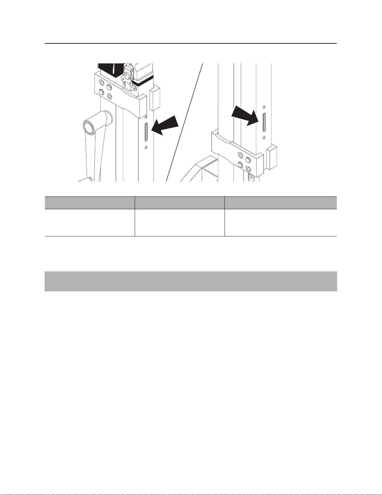
Serial Number Location
Serial Number Location
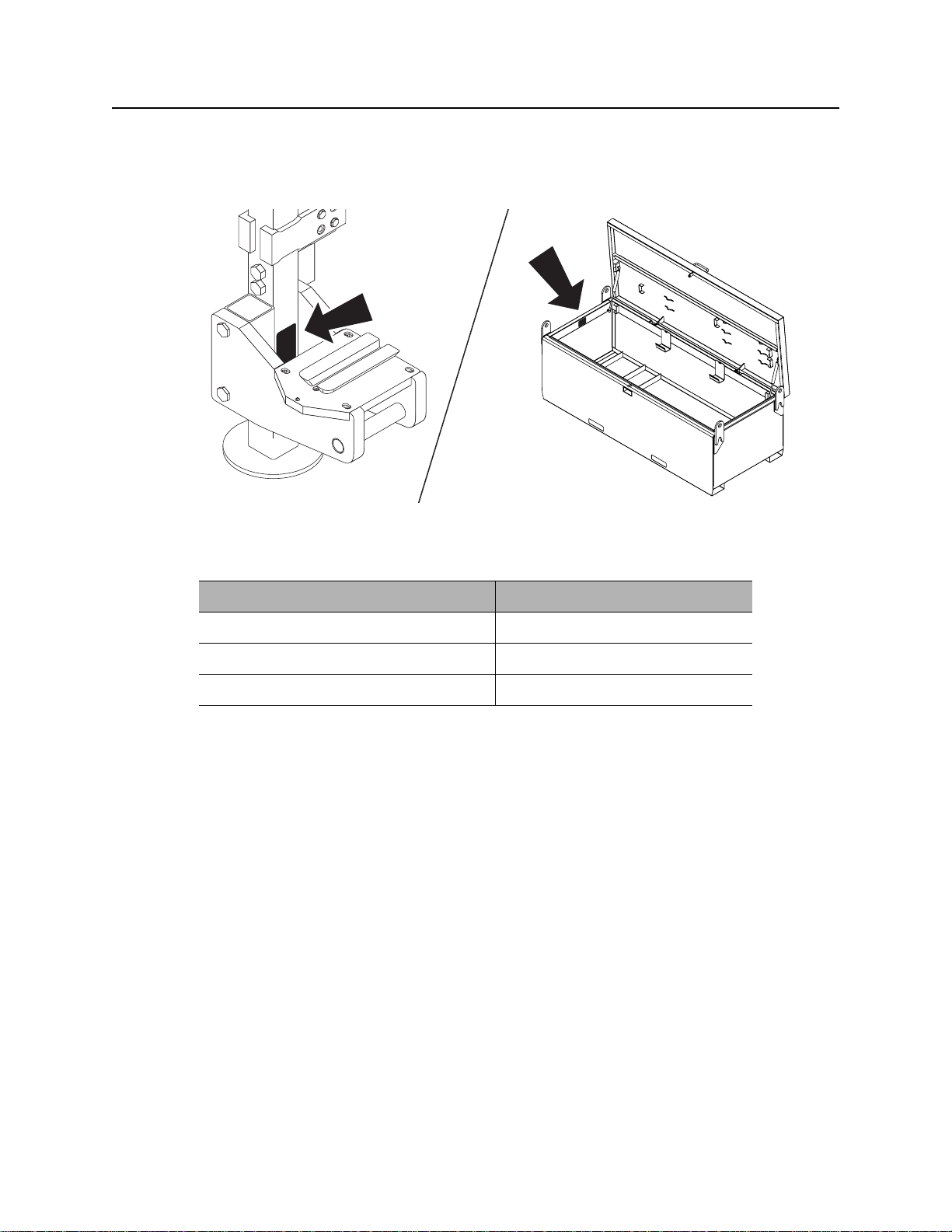
Record serial numbers and date of purchase in spaces provided. Serial numbers are located as shown.
e14om007t.eps
Item
date of purchase:
8500GP grade pole serial number:
OnGrade system serial number:
CMW

OnGrade Operator’s Manual Overview - 3
Intended Use
Intended Use
The primary components of the OnGrade system include an 8500TK tracker, an 850BG grade beacon, an
8500GP grade pole to mount the tracker on, and grade pole extensions. Other components are a beacon
calibration fixture, a digital SmartTool level, a grade laser, a surveying rod and laser receiver, a pipe
inspection trolley with digital video camera and recorder, a cable reel for video camera power, bore plotting
software, and a steel storage box. S pecialized do wnhole tools are available to help maint ain line and grade
during the bore.
The system is designed for operation in temperatures typically experienced in earth moving and
construction work environments. Use in any other way is considered contrary to the intended use. The
OnGrade system should be operated only by persons familiar with its particular characteristics and
acquainted with the relevant safety procedures. The system should be serviced only by Ditch Witch
Electronics repair centers.
About This Manual
This manual contains information for the proper use of this equipment. Cross references such as “See
page 50” will direct you to det ailed procedures.
Bulleted Lists
Bulleted lists provide helpful or important information or contain procedures that do not have to be
performed in a specific order.
Numbered Lists
Numbered lists contain illustration callouts or list steps that must be performed in order.
“Continued” Indicators
indicates that a procedure is continued on the next page.
CMW

Overview - 4 OnGrade Operator’s Manual
FCC Statement - Internal Transmitter
FCC Statement - Internal Transmitter
Contains FCC ID: TFB-FREESTAR
Contains IC: 5969A-FREESTAR
This device complies with Part 15 of the FCC Rules. Operation is subject to the following two conditions:
(1) this device may not cause harmful interference, and (2) this device must accept any interference
received, including interference that may cause undesired operation.
Changes or modifications not expressly approved by The Charles Machine Works, Inc. could void the
user’s authority to operate the equipment.
N 16819
CMW

OnGrade Operator’s Manual Foreword - 5
Foreword
This manual is an important part of your equipment. It provides safety information and operation
instructions to help you use and maintain your Ditch Witch equipment.
Read this manual before using your equipment. Keep it with the equipmen t at all times for future reference.
If you sell your equipment, be sure to give this manual to the new owner.
If you need a replacement copy, contact your Ditch Witch dealer. If you need assistance in locating a
dealer, visit our website at www.ditchwitch.com or write to the following address:
The Charles Machine Works, Inc.
Attn: Marketing Department
PO Box 66
Perry, OK 73077-0066
USA
The descriptions and specifications in this manual are subject to change without notice. The Charles
Machine Works, Inc. reserves the right to improve equipment. Some product improvements may have
taken place after this manual was publishe d. For the latest information on Ditch Witch equipment, see your
Ditch Witch dealer.
Thank you for buying and using Ditch Witch equipment.
CMW

Foreword - 6 OnGrade Operator’s Manual
OnGrade
Operator’s Manual
Issue number 1.0/OM-2/10
Part number 053-1393
Copyright 2010
by The Charles Machine Works, Inc.
, Ditch Witch, CMW, AutoCrowd, Jet Trac, Roto Witch, Subsite, Fluid Miser,
Power Pipe, Super Witch, Pierce Airrow, The Underground, The Underground Authority Worldwide, and
Zahn are registered trademarks of The Ch ar les Mac hin e Works, Inc.
This product is covered by the following patents:
U.S. 7510029; DE (Germany) 602006008328.9-08; UK 1929125; other patents pending.
CMW

OnGrade Operator’s Manual Contents - 7
Content s
Overview
machine serial number, information about the type of work this machine is designed
to perform, basic machine components, and how to use this manual
Foreword
part number, revision level, and publication date of this manual, and factory contact
information
Safety
machine safety alerts and emergency procedures
Controls
machine controls and how to use them
Conduct OnGrade Bore
procedures for setting up, drilling, and backreaming an OnGrade job
Grade Boring Concepts
basic information for grade boring
Systems and Equipment
downhole tools, OnGrade Management System software, inspection tools, and job
box
1
5
9
13
25
49
41
Complete OnGrade Job
procedures for inspecting the installation and leaving jobsite
Service
service intervals and instructions for this machine
Specifications
machine specifications including weights and measurements
Support
the warranty policy for this machine, and procedures for obtaining warranty
consideration and training
37
53
57
59
CMW

Contents - 8 OnGrade Operator’s Manual
CMW

OnGrade Operator’s Manual Safety - 9
Safety
Chapter Contents
Guidelines . . . . . . . . . . . . . . . . . . . . . . . . . . . . . . . . 10
Safety Alert Classifications . . . . . . . . . . . . . . . . . . 11
Safety Alerts . . . . . . . . . . . . . . . . . . . . . . . . . . . . . . 12
CMW

Safety - 10 OnGrade Operator’s Manual
Guidelines
Guidelines
Follow these guidelines before operating any jobsite equipment:
• Complete proper training and read operator’s manual before using equipment.
• Contact One-Call (888-258-0808) and any utility companies which do not subscribe to One-Call. Have
all underground pipes and cables located and marked before operating equipment. If you damage a
utility, contact utility company.
• Classify jobsite based on its hazards and use cor rect tools and machin ery, safety equipment, and work
methods for jobsite.
• Mark jobsite clearly and keep spectators away.
• Wear personal protective equipment.
• Review jobsite hazards, safety and emergency procedures, and individual responsibilities with all
personnel before work begins.
• Replace missing or damaged safety signs.
• Use equipment carefully. Stop operation and investigate anything that does not look or feel right.
• Contact your equipment dealer if you have any question about operation, maintenance, or equipment
use.
CMW

OnGrade Operator’s Manual Safety - 11
Safety Alert Classifications
Safety Alert Classifications
These classifications and the icons defined on the following pages work together to alert you to situations
which could be harmful to you, jobsite bystanders or your equipment. When you see these words and
icons in the book or on the unit, carefully read and follow all instructions. YOUR SAFETY IS AT STAKE.
Watch for the three safety alert levels: DANGER, WARNING and CAUTION. Learn what each level
means.
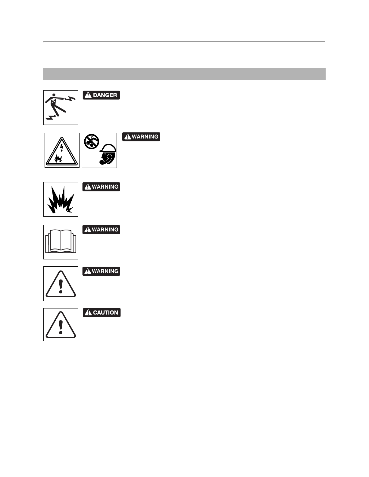
indicates an imminently hazardous situation which, if not avoided, will result in death or
serious injury.
indicates a potentially hazardous situation which, if not avoided, could result in death or
serious injury.
indicates a potentially hazardous situation which, if not avoided, may result in minor or
moderate injury.
Watch for two other words: NOTICE and IMPORTANT.
NOTICE can keep you from doing something that might damage the unit or someone's property. It can also
alert you against unsafe practices.
IMPORTANT can help you do a better job or make your job easier in some way.
CMW
Safety - 12 OnGrade Operator’s Manual
Safety Alerts
Safety Alerts
IMPORTANT: See drilling unit operator’s manual for others hazards related to drilling activities.
Electric shock. Contacting electric lines will cause death or serious injury.
Know location of lines and stay away.
Jobsite hazards could cause death or serious injury. Use
correct equipment and work methods. Use and maintain proper safety
equipment.
Explosion possible. Serious injury or equipment damage could occur.
Follow directions carefully .
Incorrect procedures could result in death, injury, or property damage.
Learn to use equipment correctly.
Moving traffic - hazardous situation. Death or serious injury could result.
Avoid moving vehicles, wear high visibility clothing, post appropriate warning signs.
Potential radio frequency (RF) hazard. Operating this device within 4” (100
mm) of your body may cause RF exposure levels to exceed FCC RF exposure limits and
should be avoided.
NOTICE: The Laser Reference AS2 is a Class II laser. The normal blink, or eye-aversion, reflex is
sufficient to prevent optical damage due to incidental viewing of a Class II laser. Do not look or stare into
laser beam.
CMW

OnGrade Operator’s Manual Controls - 13
Controls
Chapter Contents
Grade Pole . . . . . . . . . . . . . . . . . . . . . . . . . . . . . . . 14
• Controls . . . . . . . . . . . . . . . . . . . . . . . . . . . . . . . . . . . . . . . . . . . . . . . . .14
• Indicators . . . . . . . . . . . . . . . . . . . . . . . . . . . . . . . . . . . . . . . . . . . . . . . .15
• Detectors . . . . . . . . . . . . . . . . . . . . . . . . . . . . . . . . . . . . . . . . . . . . . . . .16
Laser, Level, and Camera . . . . . . . . . . . . . . . . . . . 16
8500TK Grade Mode . . . . . . . . . . . . . . . . . . . . . . . 17
• Icons . . . . . . . . . . . . . . . . . . . . . . . . . . . . . . . . . . . . . . . . . . . . . . . . . . . .17
• Buttons . . . . . . . . . . . . . . . . . . . . . . . . . . . . . . . . . . . . . . . . . . . . . . . . . .20
• Menu . . . . . . . . . . . . . . . . . . . . . . . . . . . . . . . . . . . . . . . . . . . . . . . . . . .21
CMW
Controls - 14 OnGrade Operator’s Manual
Grade Pole
Grade Pole
Controls
1
2
3
e14om001t.eps
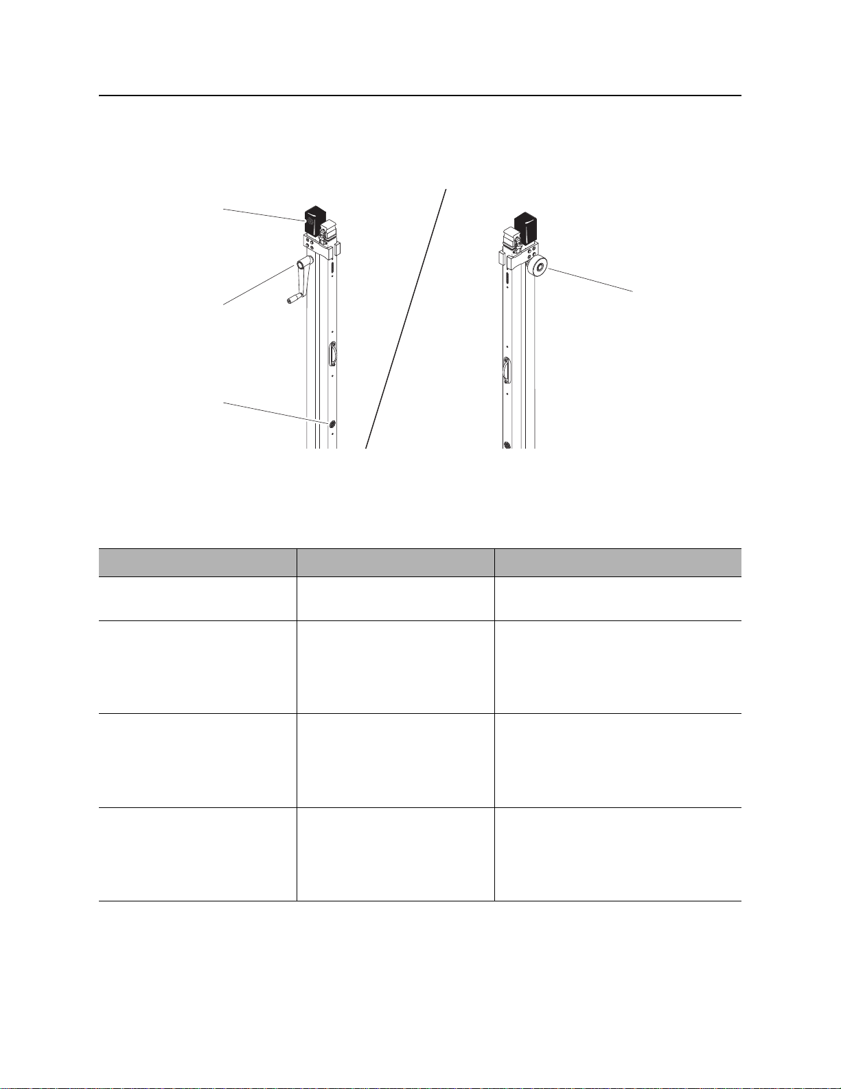
1. Depth button
2. Handle
Item Description Notes
1. Depth button To take depth reading and
send it to tracker, press.
2. Handle To raise sensor, turn
clockwise.
To lower sensor, turn counterclockwise.
3. On/Off button
4. Lock
Grade pole sends information only
when green indicator is lit.
4
3. On/Off button To turn grade pole on, press
until blue light in comes on.
To turn grade pole off, press
and release.
4. Lock To lock pole into position, turn
counter-clockwise.
To unlock pole, turn
clockwise.
CMW
To change communication channel,
see “Change Grade Pole Channel” on
page 34.
OnGrade Operator’s Manual Controls - 15
Grade Pole
Indicators
2
1
e14om004t.eps
1. Low/High indicators 2. On-grade indicator
Item Description Notes
1. Low/High indicators Upper and lower (red) lights
indicate direction to adjust
pole to center laser plane in a
laser detector.
2. On-grade indicator Center (green) light indicates
laser plane is centered in one
of the laser detectors.
Upper light indicates pole is high.
Lower light indicates pole is low.
Take depth readings when this
indicator is on.
CMW
Controls - 16 OnGrade Operator’s Manual
Laser, Level, and Camera
Detectors
e14om011t.eps
Item Description Notes
Laser detectors Detect laser plane. No control box lights will be lit unless
one of the detectors is hit by the
rotating laser plane.
Laser, Level, and Camera
IMPORTANT: See manufacturer’s documentation for information about laser, level, and camera
controls.
CMW
OnGrade Operator’s Manual Controls - 17
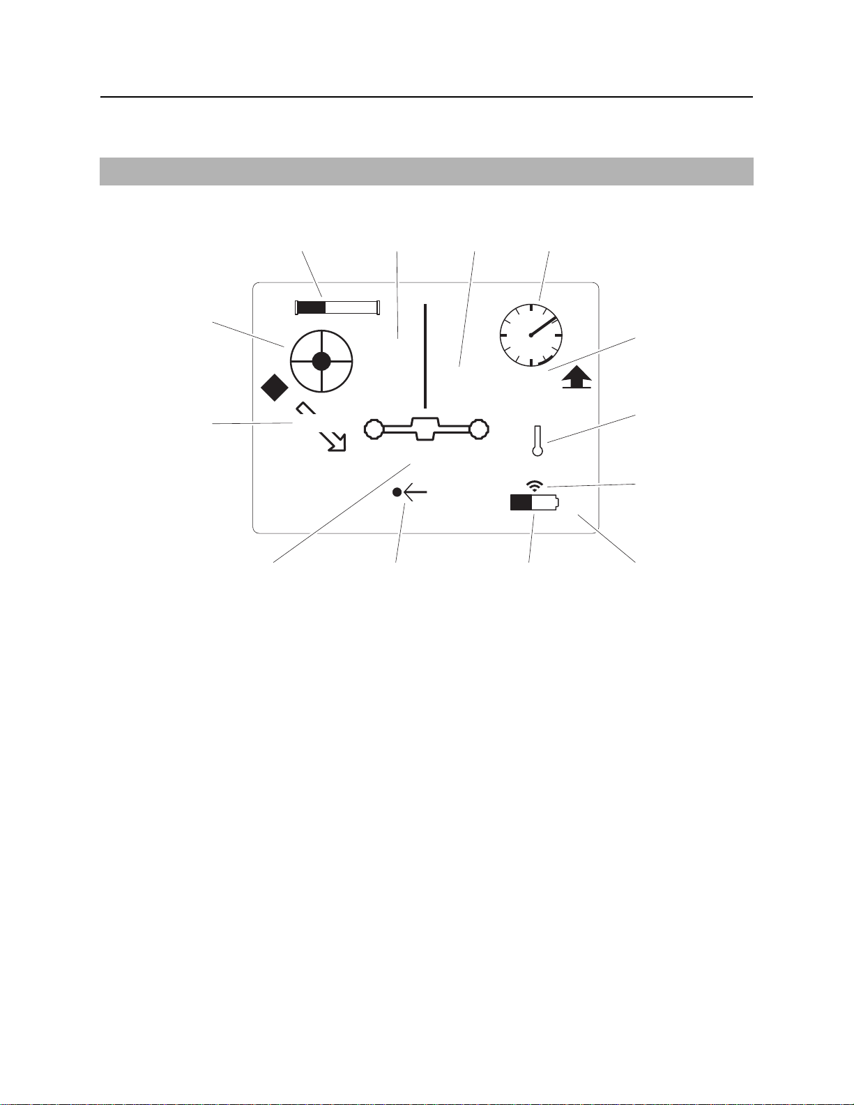
8500TK Grade Mode
8500TK Grade Mode
For standard operation, see 8500 Tracking System operator’s manual (p/n 053-1254).
Icons
e14om009t.eps
13
12
12
45.2”
0.1%
11
10
+61”
15”
4”
3
4
5
54°
6
72°F
7
11k
89
1. Beacon battery life indicator
2. Laser plane height above ground
3. Laser plane distance to center of beacon
4. Beacon roll indicator
5. Beacon roll value
6. Beacon temperature indicator
7. Communication indicator
8. Beacon frequency indicator
9. Tracker battery indicator
10. Beacon left/right distance indicator
11. Beacon depth below ground surface
12. Beacon pitch indicator
13. Virtual bubble level
CMW
Controls - 18 OnGrade Operator’s Manual
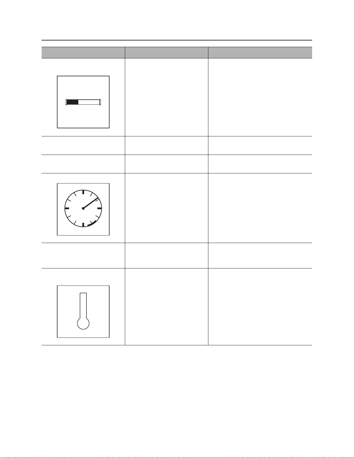
8500TK Grade Mode
Item Description Notes
1. Beacon battery life
indicator
Graphically indicates battery
life remaining.
If beacon is within 5 minutes
of entering sleep mode, a
countdown timer will appear
below icon.
An “L” appears in the icon if a
c00ic072t.eps
2. Laser plane height
above ground
3. Laser plane distance to
center of beacon
Lithium battery is installed.
Distance from the laser plane
to the ground surface.
Distance from the laser plane
to the center of the beacon.
4. Beacon roll indicator Graphically indicates
beacon’s roll position.
c00ic073t.eps
5. Beacon roll value Numerically displays
beacon’s roll position in
degrees, minutes or hours.
6. Beacon temperature
indicator
Displays beacon temperature
and flashes if temperature
becomes too high.
Icon darkens as temperature
rises and temperature is
displayed numerically below
the icon.
c00ic074t.eps
IMPORTANT: An audible warning is
activated when beacon temperature is
155°F (68°C).
CMW

OnGrade Operator’s Manual Controls - 19
8500TK Grade Mode
Item Description Notes
7. Communication
indicator
c00ic075t.eps
8. Beacon frequency
indicator
9. Tracker battery
indicator
Indicates tracker is
transmitting.
Displays “11k” when high
frequency beacon is selected.
Displays “2k” when low
frequency beacon is selected.
Indicates amount of battery
power remaining for the
tracker.
Flashes when batteries need
to be replaced.
c00ic076t.eps
10. Beacon left/right
distance indicator
c00ic077t.eps
11. Beacon depth below
ground surface
Indicates left/right offset with
respect to center of beacon
and middle of tracker handle.
Distance from the ground
surface directly below the
tracker to the center of the
beacon plane.
Tracker provides both graphical and
numeric offset information.
CMW

Controls - 20 OnGrade Operator’s Manual
8500TK Grade Mode
Item Description Notes
12. Beacon pitch indicator Displays pitch of beacon in
percent grade or degrees.
The arrow behind the value
0.1%
c00ic080t.eps
indicates whether pitch is
positive or negative.
13. Virtual bubble level Graphically represents the tilt
of the grade pole.
c00ic081t.eps
Buttons
See 8500 Operator’s Manual for information about these controls.
IMPORTANT: Location and depth
estimates are best when grade pole is
plumb.
CMW

OnGrade Operator’s Manual Controls - 21
8500TK Grade Mode
Menu
Overview
e14om010t.eps
1. Drill-Thru mode
12
3
1
2
4
+
-
6
501
0.1%
5
4. Service menu
3
4
2. Beacon settings
3. Radio options
5. Display settings
6. System settings
Item Description Notes
1. Drill-Thru mode Highlight icon and press
select to enter the drill-thru
mode.
c00ic079t.eps
CMW

Controls - 22 OnGrade Operator’s Manual
8500TK Grade Mode
Item Description Notes
2. Beacon settings Highlight icon and press
select to enter the “beacon
settings” menu.
3
1
2
4
c00ic082t.eps
3. Radio options Highlight icon and press
select to enter the “radio
options” mode.
c00ic083t.eps
4. Service menu Highlight icon and press
select to enter “service
menu.”
See “Beacon Settings” on page 23.
See “Radio Options” on page 24.
See “Service Menu” on page 24.
c00ic084t.eps
5. Display settings Highlight icon and press
select to enter the “display
settings” menu.
501
0.1%
c00ic085t.eps
6. System settings Highlight icon and press
select to enter the “system
settings” menu.
+
-
c00ic086t.eps
See “Display Settings” on page 23.
See “System Settings” on page 24.
CMW

OnGrade Operator’s Manual Controls - 23
8500TK Grade Mode
Descriptions
Display Settings
Description Notes
LCD brightness Controls LCD backlight intensity.
Available settings: 0 (off) to 100 (brightest, default).
LCD contrast Controls contrast of LCD.
Available settings: -20 (lighter) to 20 (darker), 0 is default.
Units Controls displayed units of depth values, tempera tures and other
numbers.
Available distance settings: inches, ft in (default), decimal ft, meters,
centimeters.
Depth disp. time Controls how long depth information is locked on the screen after
pressing depth button.
Available settings: 0-60 seconds, 5 is default.
Roll angle disp. Controls display of numerical value of the roll indicator.
Available settings: off (default), degr ees, minutes, hours.
Pitch disp. Controls display of beacon pitch indicator.
Available settings: percent (default), degrees.
Beacon Settings
Description Notes
Beacon freq. Sets tracker receiving frequency.
Available settings: high (default), low.
Beacon calibration Calibrates tracker to beacon.
Roll calibration Sets roll position for beacon equivalent to bit pointing up (12 o’clock, 0
minutes, 0°).
Pitch calibration Sets 0.0% pitch position for grade beacon (1.0% limit).
Depth adjustment Tracker automatically compensates for the 12” (30 cm) the tracke r is
above the ground when the grade pole is zeroed.
Changes built-in adjustment of depth measurements.
CMW

Controls - 24 OnGrade Operator’s Manual
8500TK Grade Mode
Radio Options
Description Notes
Radio power Turns radio on and off.
Available settings: on (default), off.
Channel Sets telemetry channel
Available settings: 1 (default) through 15
OnGrade channel Sets channel for OnGrade pole communication
Available settings: 1 (default) through 3
Tracker Control Enables or disables thrust and rotation of drilling unit.
Available settings: Rig ON, Rig OFF (default).
Tracker Control code Selects code for Tracker Control feature corresponding to code on
display.
System Settings
IMPORTANT: Warning sounds such as beacon temperature alert are always audible.
Description Notes
Language Controls user interface language.
Tracker sleep Controls tracker sleep feature.
Available settings: enabled (default), disabled.
Volume Controls volume of the signal sound and sound effects.
Available settings: mute, low, med, high (default).
Battery status Displays available battery information
Service Menu
Description Notes
About Lists hardware and software versions, serial number, and copyright
information.
Uptime Displays uptime and life timers.
Support Enters support menu.
Factory Enters factory menu. Password protected.
CMW

OnGrade Operator’s Manual Conduct OnGrade Bore - 25
Conduct OnGrade Bore
Chapter Contents
OnGrade Process Overview . . . . . . . . . . . . . . . . . 26
Calibrate System . . . . . . . . . . . . . . . . . . . . . . . . . . 29
• Set Up Fixture . . . . . . . . . . . . . . . . . . . . . . . . . . . . . . . . . . . . . . . . . . . .29
• Calibrate Depth, Roll, and Pitch . . . . . . . . . . . . . . . . . . . . . . . . . . . . . . .29
Set Up Laser Plane . . . . . . . . . . . . . . . . . . . . . . . . 31
• On Bore Path . . . . . . . . . . . . . . . . . . . . . . . . . . . . . . . . . . . . . . . . . . . . .31
• Extension Pole . . . . . . . . . . . . . . . . . . . . . . . . . . . . . . . . . . . . . . . . . . . .32
• Offset . . . . . . . . . . . . . . . . . . . . . . . . . . . . . . . . . . . . . . . . . . . . . . . . . . .32
• Repositioning During Bore . . . . . . . . . . . . . . . . . . . . . . . . . . . . . . . . . . .33
Take Readings . . . . . . . . . . . . . . . . . . . . . . . . . . . . 34
• Change Grade Pole Channel . . . . . . . . . . . . . . . . . . . . . . . . . . . . . . . . .34
• Zero the Grade Pole . . . . . . . . . . . . . . . . . . . . . . . . . . . . . . . . . . . . . . . .34
• Initial . . . . . . . . . . . . . . . . . . . . . . . . . . . . . . . . . . . . . . . . . . . . . . . . . . . .34
• Regular . . . . . . . . . . . . . . . . . . . . . . . . . . . . . . . . . . . . . . . . . . . . . . . . . .35
• Offset . . . . . . . . . . . . . . . . . . . . . . . . . . . . . . . . . . . . . . . . . . . . . . . . . . .35
• Pitch-Only . . . . . . . . . . . . . . . . . . . . . . . . . . . . . . . . . . . . . . . . . . . . . . . .35
• Drill-Thru . . . . . . . . . . . . . . . . . . . . . . . . . . . . . . . . . . . . . . . . . . . . . . . .36
Correct Depth . . . . . . . . . . . . . . . . . . . . . . . . . . . . . 36
CMW

Conduct OnGrade Bore - 26 OnGrade Operator’s Manual
OnGrade Process Overview
OnGrade Process Overview
12
e14om005t.eps
1. start pit
2. laser plane
3. grade pole and tracker
1. Determine start and end pits. See “Job Plans” on page 38.
2. Select downhole tools for pilot bore. See “Downhole Tools” on page 42.
4. end pit
5. tripod and laser
3
4
5
3. Calibrate system. See “Calibrate Depth, Roll, and Pitch” on page 29.
4. Position drilling unit so that drill string is at the desired pitch and depth for at least one and a half drill
pipes before entering the start pit.
5. Set up the tripod and laser past the end pit, if possible.
IMPORTANT: Grade pole can receive laser plane (2) from up to 600’ (183 m) in low-wind
conditions.
CMW

OnGrade Operator’s Manual Conduct OnGrade Bore - 27
OnGrade Process Overview
6. Drill into the start pit and verify that drill head is at the proper depth.
Turning shaft will kill you or crush arm or leg. Stay away.
NOTICE:
• Tracker operator and drill operator should maintain two-way communication.
• Keep everyone clear of the exposed drill string.
• No one should enter pit until clear communication is given by the drill operator that the drill unit
is shut down. If using tracker control (see drilling unit), do not enter pit until tracker control is
turned off and green light on drill unit is lit.
• Drill operator should be instructed to discontinue drill string rotation as soon as drill bit exit s the
bore. Use thrust only to extend drill string beyond exit hole.
Incorrect procedures could result in death, injury, or property
damage. Learn to use equipment correctly.
NOTICE: Follow U.S. Department of Labor regulations on excavating and trenching
(Part 1926, Subpart P) and other similar regulations
7. Take measurement from the laser plane to the top of the beacon housing using surveying rod and
laser receiver that came with the laser. See laser instructions.
NOTICE: The Laser Reference AS2 is a Class II laser. The normal blink, or eye-aversion, reflex is
sufficient to prevent optical damage due to incidental viewing of a Class II laser. Do not look or
stare into laser beam.
8. Mount tracker on grade pole and turn on and zero the grade pole. See “Zero the Grade Pole” on
page 34.
9. Drill past start pit until a depth reading can be taken.
CMW

Conduct OnGrade Bore - 28 OnGrade Operator’s Manual
OnGrade Process Overview
10. Use tracker to locate drill head and take initial reading. See “Initial” on page 34. This reading from laser
plane to center of beacon is the target value for the bore.
11. Add pipe, drill in and take readings as directed below until drill head enters end pit.
IMPORTANT: Take pi tch and depth readings at the same roll position.
• pitch: every 12-18” (30-45 cm) with drill head stopped
• depth: every 5-10’ (1.5-3 m) with drill head stopped
12. Take m easurement from the laser plane to the to p of the beacon housing at t he end pit using surveying
rod and laser receiver.
NOTICE:
Turning shaft will kill you or crush arm or leg. Stay away.
• Tracker operator and drill operator should maintain two-way communication.
• Keep everyone clear of the exposed drill string.
• No one should enter pit until clear communication is given by the drill operator that the drill unit
is shut down. If using tracker control (see drilling unit), do not enter pit until tracker control is
turned off and green light on drill unit is lit.
• Drill operator should be instructed to discontinue drill string rotation as soon as drill bit exit s the
bore. Use thrust only to extend drill string beyond exit hole.
Incorrect procedures could result in death, injury, or property
damage. Learn to use equipment correctly.
NOTICE: Follow U.S. Department of Labor regulations on excavating and trenching
(Part 1926, Subpart P) and other similar regulations
Compare the measurement taken at the end pit with the measurement taken at the start pit. If the
measurements match, the drill head is precisely at the desired elevation. If offsets were used, add or
subtract the offsets out and then compare readings.
13. Remove drilling downhole tools and attach backreaming downhole tools.
14. Backream the bore and pull back product pipe using proper techniques for soil conditions and slope of
the bore. See “Process” on page 44.
CMW

OnGrade Operator’s Manual Conduct OnGrade Bore - 29
Calibrate System
Calibrate System
Set Up Fixture
1. Unfold calibration fixture away from metal
objects and on reasonably level ground.
2. Install battery in beacon and place beacon in
beacon housing.
3. Place beacon and tracker in fixture, as
shown.
• Left pod of tracker should point toward
beacon end of fixture.
• Bit end of beacon should point same
direction as tracker display.
4. Calibrate SmartTool level according to
manufacturer’s instructions.
e14om006t.eps
Calibrate Depth, Roll, and Pitch
Depth
1. Position beacon housing in appropriate position for type of housing used.
• End load housing: 12 o’clock position.
• Side load housing: beacon lid facing tracker.
2. Select “Beacon Calibration” in “Beacon Settings” menu on tracker and follow prompts. See tracker
manual.
CMW

Conduct OnGrade Bore - 30 OnGrade Operator’s Manual
Calibrate System
Roll
Turn drill housing to 12 o’clock position and verify roll position on tracker. If it is incorrect when using an
endload housing, verify that the timing slot on the front of the beacon is engaged with the locating pin in the
housing. If it is still incorrect or when using a sideload housing, select “Roll Calibration” in “Beacon
Settings” menu and follow prompts.
Pitch
1. Rotate beacon housing to appropriate
position for drilling mode.
• JT mode: 12 o’clock position
• AT mode: 9 or 3 o’clock position
2. Place level on beacon housing and adjust
rollers (shown) until housing is level (0.0%).
Select “Pitch Calibration” in “Beacon
Settings” menu and follow prompts.
e14om012t.eps
CMW

OnGrade Operator’s Manual Conduct OnGrade Bore - 31
Set Up Laser Plane
Set Up Laser Plane
12
e14om005t.eps
NOTICE: The Laser Reference AS2 is a Class II laser. The normal blink, or eye-aversion, reflex is
sufficient to prevent optical damage due to incident al viewing of a Class II laser. Do not look or stare into
laser beam.
3
4
5
On Bore Path
The laser system is limited by line of sight. Setting up with that in mind can minimize how many times the
laser must be repositioned during the bore. Factors to consider include: bore slope and distance, surface
obstructions, and wind. Set up the laser and tripod in an area where they will not be bumped or disturbed
during operation. In windy conditions, set the tripod as low as possible. The laser can be set up directly on
the bore path or it can be offset to avoid line-of-site obstructions.
1. Set up tripod (5) past end pit (4) and inline with bore path, if possible.
2. Set laser plane slope. See laser operator’s manual and “Laser Plane” on page 38.
• Slope on laser is indicated in percent (%) and is the amount of rise or drop of the laser plane in feet
over a 100’ linear run.
• The slope of the laser plane can be adjusted from 0 to 25 %.
• Set up laser plane so that it is not at eye
level for the grade pole/tracker operator.
3. Align laser unit so that alignment bumps (2)
on top of unit are parallel with the desired
bore path (1).
e14om013t.eps
1
2
CMW

Conduct OnGrade Bore - 32 OnGrade Operator’s Manual
Set Up Laser Plane
Extension Pole
Use up to two extension poles to raise the upper laser plane receptor.
1. Remove cap from top of grade pole.
2. Install cap on top of extension pole and secure with clamps.
3. Insert extension pole into top of grade pole and secure with clamps.
IMPORTANT: Grade pole will not work without cap installed.
Offset
1. Find or make a point (fence post or stake)
parallel to the bore path that is the same
distance from the bore path (1) as the laser
(3).
2. Use the alignment bumps to align the laser
with the reference point.
12
e14om015t.eps
3
CMW

OnGrade Operator’s Manual Conduct OnGrade Bore - 33
Set Up Laser Plane
Repositioning During Bore
12
3
A
B
e14om018t.eps
1. Set up laser in front of obstruction (laser position 1).
2. When it is time to reposition the laser, use laser receiver to detect laser plane and make a mark on a
reference point (telephone pole or other stable object).
3. Move up the reference point a known distance (A) that will allow obstruction to be cleared.
4. Set up laser on other side of obstruction (laser position 2) and t ake readings until it is time to repositio n
the laser again.
5. Use laser receiver detect laser plane and make a mark on a reference point past the end pit.
6. Make a second mark that is a known distance (B) below the laser plane.
7. Set up laser (laser position 3) and finish taking readings.
CMW

Conduct OnGrade Bore - 34 OnGrade Operator’s Manual
Take Readings
Take Readings
Change Grade Pole Channel
1. With grade pole off, press and hold power button until grade pole comes on and blue light turns purple.
2. Look at indicator lights to determine current channel. Uppe r light is channel 1, ce nter light is channel 2,
and lower light is channel 3.
3. Press depth button to cycle through channels.
4. Press and hold depth button once desired channel is selected.
Zero the Grade Pole
IMPORTANT: Repeat this procedure each time the tracker and grade pole are turned on.
When grade pole is started up, all lights on the control box will blink. This indicates the grade pole must be
“zeroed.”
1. Lower the upper pole to the stop.
2. Press the depth button.
The lights will blink and only the blue light on the depth button will remain on.
Initial
1. Ensure the tracker and laser detectors are facing the laser and use tracker to locate beacon housing.
See tracker manual.
2. Once beacon housing is located, raise grade pole and watch three indicator lights on control housing.
3. Once the middle (green) light is on, pre ss the depth b utton on th e grade po le and then p ress the depth
button on the tracker.
4. The tracker display will switch to a screen with a virtual level bubble in the upper left corner if the
tracker picked up the depth information from the grade pole.
IMPORTANT: The tracker might not pick up the depth information on the first try. Repeat step 4
until tracker switches modes.
CMW

OnGrade Operator’s Manual Conduct OnGrade Bore - 35
Take Readings
Regular
1. Use tracker arrows to get grade pole close to the beacon.
2. Check virtual bubble level to ensure grade pole is straight up and down .
3. Gradually move the base until the arrows become black diamonds.
4. Adjust grade pole until middle (green) light comes on.
5. Look at bubble level on tracker to verify grade pole is still straight up and down.
6. Press depth button on grade pole to take depth reading. If depth does not register, press again.
Offset
When an obstruction prevents the operator fro m
getting directly over the beacon, use the offset
location mode of the tracker with th e g rade po le to
locate beacon from the side of the bore path.
Return to regular locating once obstruction is no
longer an issue. The 360° laser plane allows for
offset location by the grade pole as well. See
“Laser Plane” on page 38.
e14om022t.eps
Pitch Only
In situations where a large iron or steel object on the ground surface is near the tracker, the depth reading
from the tracker will probably be incorrect. In most instances, the depth will be shallower than the actual
depth of the drill head. This will cause the total distance from the laser plane to the drill head to be off by
that amount. In most situations, this error will be apparent when the operator sees a large discrepancy
between the total depth reading near the obstruction and the previous readings. In this situation, the drilling
unit operator must disregard the depth and use only the pitch information from the tracker until the drill
head passes the obstruction and a good depth reading is taken.
CMW

Conduct OnGrade Bore - 36 OnGrade Operator’s Manual
Correct Depth
Drill-Thru
Drill-thru mode on the tracker provides left/right
guidance information as well as pitch information.
Depth information provided when using drill-thru
mode can be ignored when conducting an
OnGrade bore.
IMPORTANT: See tracker manual for additional
drill-thru mode instructions.
1. Stre tch a string on the ground surface along
the bore path (2).
2. Place tracker ahead of the front of the drill
head between the drilling unit (1) and laser (5)
with the center line of the tube holding the outer pods directly over the str ing and the left pod (3 ) toward
the drilling unit.
3. Use left/right information to steer drill head and monitor pitch information closely.
The tracker must remain in front of the drill head and turned sideways with the left pod toward the drilling
unit. The center line of the tube holding the outer pods should be directly over the desired line of the bore.
12
e14om014t.eps
3
4
5
Correct Depth
Correcting depth gradually is critical to the success of a gr ad e bor e.
Downhill or Downgrade Bore
If the measured depth from the laser plane to the beacon ever starts to become deeper than the target
depth, the driller should drill at a pitch slightly flatter than the the target grade until the grade of the bore
naturally catches up with the fall of the target grade.
IMPORTANT: Do not drill at a positive pitch to correct depth. This will create a dip in the bore path.
Uphill or Upgrade Bore
If the measured depth from the laser plane to the beacon ever starts to become shallower than the target
depth, the driller should drill at a pitch slightly flatter than the the target grade until the grade of the bore
naturally catches up with the rise of the target grade.
IMPORTANT: Do not drill at a negative pitch to correct depth. This will create a hump in the bore path.
CMW

OnGrade Operator’s Manual Grade Boring Concepts - 37
Grade Boring Concepts
Chapter Contents
Theory of Operation . . . . . . . . . . . . . . . . . . . . . . . . 38
• Job Plans . . . . . . . . . . . . . . . . . . . . . . . . . . . . . . . . . . . . . . . . . . . . . . . .38
• Laser Plane . . . . . . . . . . . . . . . . . . . . . . . . . . . . . . . . . . . . . . . . . . . . . .38
• Depth Limitation . . . . . . . . . . . . . . . . . . . . . . . . . . . . . . . . . . . . . . . . . . . . .
CMW

Grade Boring Concepts - 38 OnGrade Operator’s Manual
Theory of Operation
Theory of Operation
Job Plans
For most jobs, engineers will lay out the line and will establish the manhole locations, the depth the sewer
line needs to run, and the recommended grade for the installation. On jobs where a connection is being
made to an existing service, the position of the existing sewer line will dictate the depth.
Engineers commonly base the plans for a sewer line on the invert, or flowline, of the installation. This is the
elevation of the lower surface of the internal diameter of the installed pipeline. Drillers depths are from the
center of the beacon which equates to the center of the installed pipe. If the engineer has specified
elevations based on the invert, the driller must subtract half of the internal diameter of the pipe to be
installed from the values given by the engineer to obtain the correct centerline depth for the housing.
Laser Plane
The laser emits a 360° plane. This allows for offset
location of the laser plane by the grade pole.
The laser plane is also directional meaning that it
will slope up from horizontal in one direction and
down from horizontal in the other direction.
e14om017t.eps
e14om023t.eps
CMW

OnGrade Operator’s Manual Grade Boring Concepts - 39
Theory of Operation
Depth Limitation
The depth measurement accuracy of the 8500T K tracker is reduced when the beacon is more than 30’ (9.1
m) below the tracker or 29’ (8.8 m) below the ground surface when tracker is mounted on the grade pole.
For short sections of a bore which are deeper than this, continue drilling using only pitch information until
the depth is less than 29’ (8.8 m).
IMPORTANT: CMW does not recommend using the On-Grade system for installations deeper than 29’
(8.8 m).
CMW

Grade Boring Concepts - 40 OnGrade Operator’s Manual
Theory of Operation
CMW

OnGrade Operator’s Manual Systems and Equipment - 41
Systems and Equipment
Chapter Contents
Dowhole Tools . . . . . . . . . . . . . . . . . . . . . . . . . . . . 42
• Pilot bore . . . . . . . . . . . . . . . . . . . . . . . . . . . . . . . . . . . . . . . . . . . . . . . .42
• Backream . . . . . . . . . . . . . . . . . . . . . . . . . . . . . . . . . . . . . . . . . . . . . . . .43
OnGrade Management System Software . . . . . . . 45
Inspection Tools . . . . . . . . . . . . . . . . . . . . . . . . . . . 45
• Beacon trolley . . . . . . . . . . . . . . . . . . . . . . . . . . . . . . . . . . . . . . . . . . . .45
• Camera/Video recorder . . . . . . . . . . . . . . . . . . . . . . . . . . . . . . . . . . . . .46
Job Box . . . . . . . . . . . . . . . . . . . . . . . . . . . . . . . . . . 47
• Stow Tools . . . . . . . . . . . . . . . . . . . . . . . . . . . . . . . . . . . . . . . . . . . . . . .47
• Lift . . . . . . . . . . . . . . . . . . . . . . . . . . . . . . . . . . . . . . . . . . . . . . . . . . . . .48
• Tie Down . . . . . . . . . . . . . . . . . . . . . . . . . . . . . . . . . . . . . . . . . . . . . . . .48
CMW

Systems and Equipment - 42 OnGrade Operator’s Manual
Downhole Tools
Downhole Tools
Pilot Bore
• Endload beacon housing: provides more
torsional stiffness and more uniform beacon
signal strength regardless of roll position
compared to sideload housing.
e14om025t.eps
• Pocket bit (1) or slant-faced head with
grade Tuff bit (2): both cut a hole slightly
larger than the diameter of the beacon housing
for a straighter bore path. The pocket bit is
useful in stiffer soils and the grade Tuff bit is
useful for steering in soft soil conditions.
2
• Grade adaptor (tailpiece): holds rear end of
beacon housing centered in the bore hole to
give truer pitch readings.
1
e14om024t.eps
e14om026t.eps
CMW

OnGrade Operator’s Manual Systems and Equipment - 43
Downhole Tools
• Grade transition sub: is stiffer than standard
transition subs and helps maintain a straight
bore path. Reduces the drill head’s tendency
to deviate from a straight line.
e14om029t.eps
Backream
Tools
• Flail backreamer: provides very thorough
mixing action to create a flowable soil slurry
and has support wings to help maintain the
vertical position of the reamer in the bore hole
in softer soils.
• Centering tools: are placed in front of the
backreamer on second and third backreaming
passes to help hold the reamer in the center of
the bore hole. This helps reduce the tendancy
of the reamer to lower the bore hole on
subsequent backreaming passes.
e14om027t.eps
e14om028t.eps
CMW

Systems and Equipment - 44 OnGrade Operator’s Manual
Downhole Tools
Process
The tools, fluid rate, drilling fluid and process used for backreaming and pulling in pipe will vary based on
soil conditions and operator’s experience and knowledge of the soils in the area. A few key points to
consider are:
• Make as few passes through the bore hole as possible. The walls of the bore may sof ten with the
addition of drill fluid and additional passes may cause the backreamer or tooling to sink below the
desired line for the bore.
• Monitor the flow of spoils from the far end of the bore hole during backr eaming. If spoils are not leaving
the bore, the drilling fluid could frac-out and cause the ground to hump. This hump in the bore could
cause the installed pipe to move up and create an unacceptable dip in the installation.
• If drilling unit operator cannot be confident of keeping spoils return while pulling in the product behind
the backreamer, backream the hole without pulling in pipe. Push back through the hole with pilot drill
head and then pull in product without reaming.
CMW

OnGrade Operator’s Manual Systems and Equipment - 45
OnGrade Management System Software
OnGrade Management System Software
The OnGrade Management System (OGMS) plotting software is configured to work with the information
taken at the start and end of a gravity sewer bore, and with the information obtained from the grade pole
during the bore. The software can be used during the bore by connecting a laptop computer to the output
port on the drilling unit display. The data can also be logged onto the SD card in the display and then
downloaded and plotted using OGMS after the bore is completed. Data can also be entered manually.
Although OGMS bears some similarity to the Trac Management System (TMS) software, OGMS is not a
bore planning tool. It assumes the route for the gravity sewer line will be a direct shot and has been laid ou t
by a planning engineer or designer ahead of time. It also takes into account the special information
provided by the grade pole and the beacon trolley to plot the features on the graph.
OGMS software can plot the bore as it progresses and also plot the installed pipe. The plot of the installed
pipe can be printed to provide an as-built record for the job.
Inspection Tools
Beacon Trolley
1. Install sideload isolator onto the clocking end of the beacon (away from the battery cap) used for the
bore.
2. Place beacon into beacon trough on grade trolley with battery cap toward the back end of the trolley
(away from the camera).
3. Ensure beacon is seated all the way down in the trough.
4. Rotate the trolley on its axis a couple of times to ensure the beacon is awake.
5. Seat trolley in the V-groove on the beacon calibration fixture.
6. Place Smart Tool level across the edges of the roller on one side of the beacon trolley.
7. Adjust rollers until the Smart Level indicates the trolley is level.
8. Calibrate 8500TK pitch. See tracker manual.
CMW

Systems and Equipment - 46 OnGrade Operator’s Manual
Inspection Tools
Camera/Video Recorder
Operation
IMPORTANT: See camera and video recorder operator’s manuals for operating instructions.
Connection
1. Spool off enough cable to pass competely through installed pipe.
IMPORTANT: Camera cable spool provided has 500’ (152 m) of cable. If installed pipe run is
longer than this, run trolley as far as possible and then set up trolley in other end of inst alled pipe
to record the rest of the run.
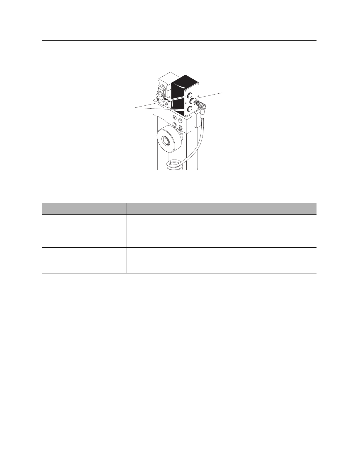
2. Remove nut on back of camera and connect
camera cable to video camera on the trolley
(1). Tighten connection firmly.
3. Seat cable gland into bracket at the back of
the trolley (2). Tighten thumb nut to prevent
cable from pulling on the back of the camera
as the trolley is pulled through the pipe.
12
4. Connect 12V power supply to the power
connection on cable spool.
5. Connect the digital video recorder to the
connection on the cable spool.
6. Verify the recorder is receiving video feed
from the camera.
7. Verify SD card is installed in the recorder if
digital recording of video feed from the camera is needed.
8. Press “record” on the video recorder to begin video capture.
e14om019t.eps
CMW

OnGrade Operator’s Manual Systems and Equipment - 47
Job Box
Job Box
Stow Tools
Place all OnGrade system components in job box
for transport from the jobsite.
Lid
1. Trolley
2. Surveyor’s rod
3. Level
12 3
e14om020t.eps
Box
12
1. Cable spool
3
4
2. Tool box
3. Calibration tool
4. Tripod
5. Laser
6. Tracker
7. Grade pole
7
e14om021t.eps
6
5
CMW

Systems and Equipment - 48 OnGrade Operator’s Manual
Job Box
Lift
Use a forklift or crane capable of supporting the
equipment's size and weight. See “S pecifications”
on page 57 or measure and weigh equipment
before lifting.
• If using forklift, slide forks into slots on sides
(as shown) or ends of box.
• If using crane, use top lift points.
e14om008t.eps
Tie Down
Properly tie down unit on truck or trailer before transport. Pass tiedown straps through top lift points or
across top of box to truck bed or trailer.
CMW

OnGrade Operator’s Manual Complete the Job - 49
Complete the Job
Chapter Contents
Inspect Installation . . . . . . . . . . . . . . . . . . . . . . . . . 50
Disconnect . . . . . . . . . . . . . . . . . . . . . . . . . . . . . . . 51
Stow Tools . . . . . . . . . . . . . . . . . . . . . . . . . . . . . . . 51
CMW

Complete the Job - 50 OnGrade Operator’s Manual
Inspect Installation
Inspect Installation
After the product pipe is pulled back, clean out the pipe and ins pe ct th e ins tallation.
1. Use surveying rod and laser receiver to ta ke distan ce measurement fr om laser plane to top o f installed
pipe at start and end pits. Ensure laser is set up exactly as it was during the bore.
2. Tie a small rope to the correct size of foam cleanout pig. Ensure the rope is longer than the installed
pipe and spool off enough rope at the pipe entrance to allow pig to pass easily through the pipe.
3. Place the pig in the pipe and use a vacuum excavator at the other end of the installed pipe to pull pig
through the pipe. If the pipe still has fluid or spoils in it, make a second pass with the pig.
4. Pour a known quantity of water in the uphill end of the installed pipe. Place a bucket at the lower end to
catch the water that comes out.
IMPORTANT:
• If installed pipe has a flat grade or long run, this process could take several minutes.
• If installed pipe has a low spot, add more water until water comes out the downhill end.
5. Install grade beacon used for the bore into the grade trolley. See “Beacon Trolley” on page 45.
6. Attach the rope to the connector on the front of the trolley.
7. If a video camera will be used, connect camera. See “Camera/Video Recorder” on page 46.
8. Begin pulling trolley through installed pipe.
9. Take pitch readings at spots where depth readings were taken during pilot bore. If this is not possible,
take readings at consistent distance increments (5-10’/1.5-3 m).
NOTICE:
• Stop trolley for 3-4 secon ds before taking pitch readings to allow beaco n pitch sensor to settle.
• Use radios to allow tracker operator to communicate with the person pulling the trolley.
10. Once trolley reaches other end of installed pipe, disconnect it from the rope. Stop the video recorder, if
used.
11. Pull trolley back through the installed pipe by reeling in the cable.
12. Transfer video and pitch information to computer.
CMW

OnGrade Operator’s Manual Complete the Job - 51
Disconnect
Disconnect
• Disconnect and store all drilling components. See drilling unit operator’s manual.
• Remove batteries and put all tracking and OnGrade components in job box and storage cases.
Stow Tools
Make sure all wrenches, bits, pullback devices, and other tools are secured on trailer.
CMW

Complete the Job - 52 OnGrade Operator’s Manual
Stow Tools
CMW

OnGrade Operator’s Manual Service - 53
Service
Chapter Contents
General Care . . . . . . . . . . . . . . . . . . . . . . . . . . . . . . 54
Troubleshoot Grade Pole . . . . . . . . . . . . . . . . . . . 54
Change Batteries . . . . . . . . . . . . . . . . . . . . . . . . . . 56
CMW

Service - 54 OnGrade Operator’s Manual
General Care
General Care
Under normal operating conditions, all OnGrade system components need only minor maintenance.
Following these care instructions can ensure longer equipment life:
• Do not drop the equipment.
• Do not expose the equipment to high heat (such as in the rear window of a vehicle).
• Clean equipment with a damp cloth and mild soap. Never use scouring powder.
• Do not immerse in any liquid.
• Inspect hardware on grade pole to ensure all fasteners are in place and properly tig htened.
• Do not mix new and used batteries.
• Remove battery if storing for an extended period.
See manufacturer’s documentation for more information on laser, level, and camera.
Troubleshoot Grade Pole
IMPORTANT: See manufacturer’s documentation for information about troub leshooting laser, level, and
camera.
Issue Possible Cause Possible Solution
Lights on control box will not
indicate a laser “hit.”
Control box lights jump between
high, low and centered.
1. Obstructions between laser
and grade pole.
2. Elevation of laser is above
or below grade pole reach.
3. Laser plane is out of
distance range.
Wind is moving tripod and
causing laser plane to waver.
1. Remove obstructions or do
an offset locate.
2. Use an extension pole on
the grade pole or reposition
laser with an offset.
3. Laser plane range is up to
600’ (183 m) in low-wind
conditions.
Set tripod as low as possible on
windy days. Use a windbreak for
tripod if possible.
If these steps do not remedy the
problem, take readings when
green light is lit and the upper
and lower lights are flashing
about the same amount of time.
CMW

OnGrade Operator’s Manual Service - 55
Troubleshoot Grade Pole
Issue Possible Cause Possible Solution
Grade pole will not communicate
with tracker.
Tracker does not take a reading
when depth button on grade
pole is pressed.
High and low indicator lights will
light on control box but not the
green centered light.
No lights will light up on control
box.
Total depth reading (laser plane
to beacon) is much differe nt than
previous readings.
1. Depth button pushed without
green light on control box lit.
2. Tracker and grade po le may
be set to different
communication channels.
Beacon is regulating power. • Try again af ter a few
Cap may be missing from grade
pole or extension.
1. Weak batteries in grade
pole.
2. Coiled cable connection is
loose.
Interference from iron or steel
object(s) at or near the ground
surface.
1. Press depth button when
green light is lit.
2. Follow tracker (see tracker
manual) and grade pole
(see page 34) instructions to
verify units are on same
channel.
seconds.
• Use PowerStick or Lithium
battery to limit beacon
regulation in rough terrain.
Install cap on top of grade pole
or uppermost extension.
1. Replace batteries in grade
pole.
2. Check cable connection on
grade pole.
See “Pitch Only” on page 35.
Upper and lower red lights come
on when depth button is
pressed.
All lights on grade pole control
box flash on and off at a regular
interval.
Grade pole batteries are low. Change batteries.
Grade pole is picking up a
flashing strobe in the area.
Check for flashing strobe lights
in the vicinity and block view of
grade pole.
CMW

Service - 56 OnGrade Operator’s Manual
Change Batteries
Change Batteries
Location Task Notes
Grade Pole Change batteries 3 “C” cell alkaline
Laser Change batteries See laser manual.
Level Change batteries See level instructions.
Camera Change batteries See camera instructions.
Tracker and
Change batteries See 8500 Tracking System
Display
Grade Pole
IMPORTANT: Do not mix ne w an d us ed
batteries.Do not mix battery brands.
Use three C-cell alkaline batteries in grade
pole.
1. Remove battery cover.
2. Insert batteries as shown.
3. Install and tighten battery cover.
4. Check operation.
IMPORTANT: Zero grad e po le each
time unit is turned on. See “Zero the
Grade Pole” on page 34.
e14om002t.eps
manual (p/n 053-1254)
+
-
+
-
+
-
1
2
CMW

OnGrade Operator’s Manual Specifications - 57
Grade Pole
Specifications
Grade Pole
H2
H1
D
W
e14om030t.eps
Dimensions U.S. Metric
H1 Height, fully lowered 67.7” 1.7 m
H2 Height, fully raised 107.1” 2.7 m
D Depth 8.3” 21.1 cm
W Width 10.5” 26.7 cm
Weight 15.6 lb 7.1 kg
Extension pole length 41.4” 1.1 m
Extension pole weight 3.2 lb 1.5 kg
Operation U.S. Metric
Operating temperature range -4°F to 122°F -20°C to 50°C
3 radio channels (2.4 GHz)
IP55 Environmental Rating: dust intrusion and low-pressure water spray
CMW

Specifications - 58 OnGrade Operator’s Manual
Job Box
Battery U.S. Metric
Type: 3 C-cell alkaline
Life (intermittent use at 70°F/21°C): 8-10 hours
Battery saver: unit reduces power consumption after 30 seconds of inactivity; unit shuts off after 30
minutes of inactivity
Job Box
LW
H
e14om031t.eps
Dimensions U.S. Metric
H Height 28.3” 718 mm
L Length 78” 1.98 m
W Width 31.5” 800 mm
Weight, empty 363 lb 165.6 kg
Weight, fully loaded 584 lb 264.9 kg
CMW

OnGrade Operator’s Manual Support - 59
Procedure
Support
Procedure
Notify your dealer immediately of any malfunction or failure of Ditch Witch equipment.
Always give model, serial number, and approximate date of your equipment purchase. This information
should be recorded and placed on file by the owner at the time of purchase.
Return damaged unit to dealer for inspection and warranty consideration if in warranty time frame.
All repairs must be done by an authorized Ditch Witch Electronics repair facility. Repairs done elsewhere
will void warranty.
Resources
Publications
Contact your Ditch Witch dealer for publications and videos covering safety, operation, service, and repair
of your equipment.
Training
For information about on-site, individualized training, contact your Ditch Witch dealer.
CMW

Warranty - 60 OnGrade Operator’s Manual
Limited Product Warranty Policy
Warranty
Limited Product W arranty Policy
Warranty Periods
New Product
A twelve-month period starts on the date of delivery to the end user:
trackers, remote displays, receivers, transmitters, radars, fault finders
A six-month period starts on the date of delivery to the end user:
directional and locate beacons
A three-month period starts on the date of delivery to the end user:
accessories: cables, clamps, canoes, bags, and adapters
Used Product (Cosmetics)
A three-month warranty starts on the date of delivery to the end user on used and refurbished products
sold from Ditch Witch Electronics dealers. Used products are non-returnable.
Service and Repair
A one-month warranty on labor st art s on the date th e unit is repai red, and a three-mo nth warranty on parts
starts on the date the unit is repaired for all products.
Extended Warranty
The extended warranty may be purchased at the time the equipment is sold or anytime within the original
warranty period. The extension is for an additional twelve or twenty-four months, for a total coverage of
twenty-four to thirty-six months. Exclusions: All beacons and accessories.
CMW

OnGrade Operator’s Manual Warranty - 61
Limited Product Warranty Policy
Details and Exclusions
• The warranty includes only Ditch Witch Electronics products and accessories that are manufactured
and distributed by Ditch Witch Electronics. The warranty compensates on defects in material or
workmanship.
• Defects will be determined through inspection by Ditch Witch Electronics or authorized repair centers.
Original purchaser must make the defective item available for inspection within 30 days of the date th e
part fails.
• The warranty is limited to replacement of the defective part. The replacement part may be new or
remanufactured. Repair and installation of defective part will be at no charge when product or item is
delivered to Ditch Witch Electronics or an authorized repair center . The product or item will be returned
at no charge for return freight.
• The warranty periods do not represent the useful life of Ditch Witch Electronics products and
accessories.
• If Ditch Witch Electronics products are purchased for commercial purposes, as defined by the
Commercial Code, no warranties extend beyond the specific terms set forth in this limited warranty. All
other provisions of this limited warranty apply, including the duties imposed.
• Ditch Witch Electronics products have been tested to deliver acceptable performance in most
conditions.
• This limited warranty applies to the original purchaser only. Some states or jurisdictions do not allow
exclusion or limitation of incidental or consequential damages, so abo ve limitation may not apply. This
limited warranty gives original purchaser specific rights that vary from state to state or jurisdiction to
jurisdiction.
• Each serial-numbered piece of equipment must be registered by the selling dealer to determine
warranty start date.
• When a registration is not received, the Ditch Witch Electronics shipping date is used to establish the
warranty period start date.
• Product inspection and estimates may require that the unit be disassembled and tested.
• Out-of-warranty inspection costs include labor accrued at the full labor rate plus return freight.
• Approved out-of-warranty repair costs include parts, labor accrued at full labor rate, plus return freight.
Revision F, September 2006
CMW

Warranty - 62 OnGrade Operator’s Manual
Limited Product Warranty Policy
CMW
 Loading...