


MV800
Operator’s
Manual
CMW
®
Issue 1.0
053-2767

MV800 Operator’s Manual Overview - 1
Overview
Chapter Contents
Serial Number Location . . . . . . . . . . . . . . . . . . . . . . 2
Intended Use . . . . . . . . . . . . . . . . . . . . . . . . . . . . . . . 2
Equipment Modification . . . . . . . . . . . . . . . . . . . . . 3
Unit Components . . . . . . . . . . . . . . . . . . . . . . . . . . . 3
Operator Orientation. . . . . . . . . . . . . . . . . . . . . . . . . 4
About This Manual . . . . . . . . . . . . . . . . . . . . . . . . . . 4
• Bulleted Lists. . . . . . . . . . . . . . . . . . . . . . . . . . . . . . . . . . . . . . . . . . . . . . .4
• Numbered Lists. . . . . . . . . . . . . . . . . . . . . . . . . . . . . . . . . . . . . . . . . . . . .4
CMW
®

Overview - 2 MV800 Operator’s Manual
Serial Number Location
Serial Number Location
Record serial numbers and date of purchase in spaces provided. MV800 serial number is located as
shown.
Date of manufacture
Date of purchase
MV800 serial number (shown)
Engine serial number
Blower serial number
Water pump serial number
Trailer serial number
Intended Use
The MV800 is a self-contained vacuum excavation unit designed to remove used drilling fluid from the
jobsite and to expose existing buried utilities. The optional reverse flow system allows for spoils transfer to
another tank. The MV800 is intended for operation in ambient temperatures from 0° to 115°F (-18° to
46°C). Use in any other way is considered contrary to the intended use.
The MV800 should be operated, serviced, and repaired only by persons familiar with its particular
characteristics and acquainted with the relevant safety procedures.
CMW
®
MV800 Operator’s Manual Overview - 3
Equipment Modification
Equipment Modification
This equipment was designed and built in accordance with applicable standards and regulations.
Modification of equipment could mean that it will no longer meet regulations and may not function properly
or in accordance with the operating instructions. Modification of equipment should only be made by
competent personnel possessing knowledge of applicable standards, regulations, equipment design
functionality/requirements and any required specialized testing.
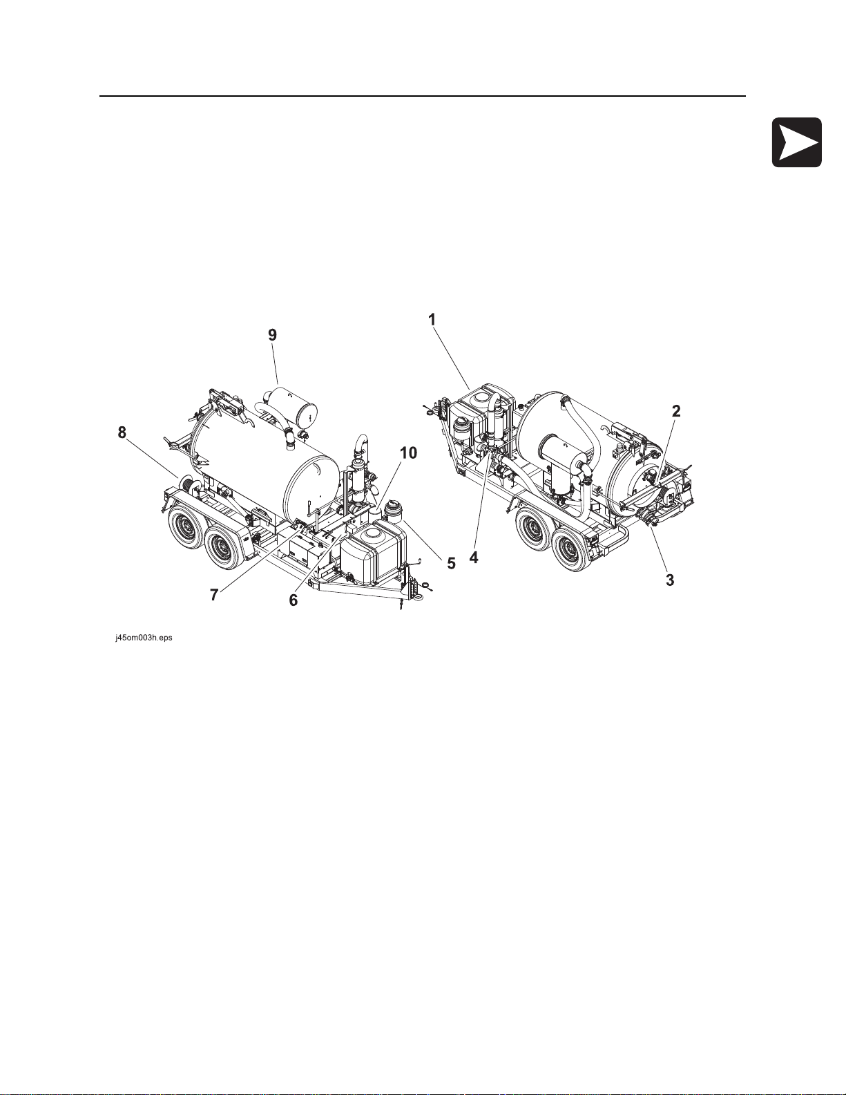
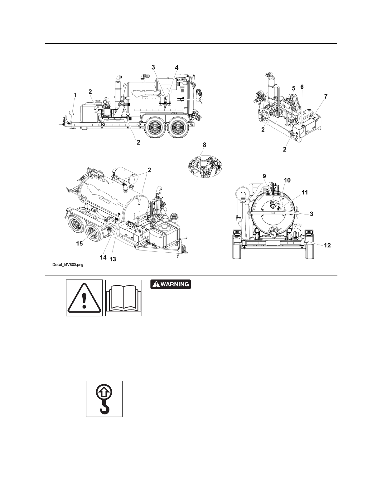
Unit Components
1. Water tank
2. Inlet valve
3. Drain/Outlet valve
4. Reverse flow valve
5. Antifreeze tank
6. Power pack
7. Operator’s station
8. Hose reel
9. Vacuum filter
10. Blower relief air filter
CMW
®
Overview - 4 MV800 Operator’s Manual
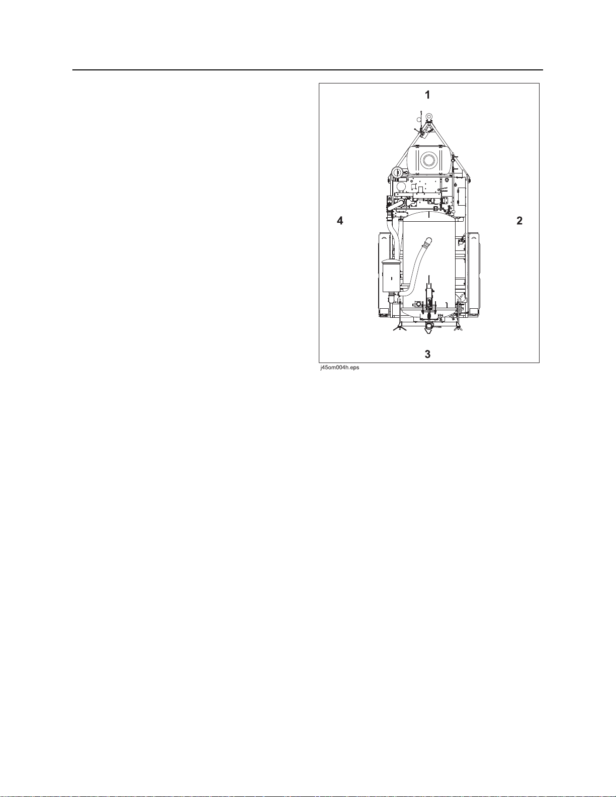
Operator Orientation
Operator Orientation
1. Front of unit
2. Right of unit
Right and left sides of machine are determined by
facing towing vehicle.
3. Rear of unit
4. Left of unit
About This Manual
This manual contains information for the proper use of this machine. See Operation Overview for basic
operating procedures. Cross references such as “See page 50” will direct you to detailed procedures.
Bulleted Lists
Bulleted lists provide helpful or important information or contain procedures that do not have to be
performed in a specific order.
Numbered Lists
Numbered lists contain illustration callouts or list steps that must be performed in order.
CMW
®

MV800 Operator’s Manual Foreword - 5
Reporting Safety Defects
Foreword
This manual is an important part of your equipment. It provides safety information and operation
®
instructions to help you use and maintain your Ditch Witch
Read this manual before using your equipment. Keep it with the equipmen t at all times for future reference.
If you sell your equipment, be sure to give this manual to the new owner.
If you need a replacement copy, contact your Ditch Witch dealer. If you need assistance in locating a
dealer, visit our website at www.ditchwitch.com or write to the following address:
The Charles Machine Works, Inc.
Attn: Marketing Department
PO Box 66
Perry, OK 73077-0066
USA
The descriptions and specifications in this manual are subject to change without notice. The Charles
Machine Works, Inc. reserves the right to improve equipment. Some product improvements may have
taken place after this manual was publishe d. For the latest information on Ditch Witch equipment, see your
Ditch Witch dealer.
equipment.
Thank you for buying and using Ditch Witch equipment.
Reporting Safety Defects
If you believe that your vehicle has a defect which could cau se a cr ash o r co uld ca use injury or death, you
should immediately inform the National Highway Traffic Safety Administration (NHTSA) in addition to
notifying the Product Safety Coordinator at The Charles Machine Works, Inc.
If NHTSA receives similar complaints, it may open an investigation, and if it finds that a safety defect exists
in a group of vehicles, it may order a recall and remedy campaign. However, NHTSA cannot become
involved in any individual problems between you, your Ditch Witch dealer, or The Charles Machine Works,
Inc.
To contact NHTSA you may either call the Auto Safety Hotline toll-free at 1-888-327-4236 (TTY: 1-800424-9153), go to http://www.safercar.gov, or write to:
Administrator
NHTSA
1200 New Jersey Avenue S.E.
Washington, DC 20590
You can also obtain other information about motor vehicle safety from http://www.safe rcar.gov.
CMW
®

Foreword - 6 MV800 Operator’s Manual
Works, Inc.
MV800
Operator’s Manual
Issue number 1.0/OM-9/14
Part number 053-2767
Copyright 2014
by The Charles Machine Works, Inc.
, Ditch Witch, and CMW are registered trademarks of The Charles Machine
U.S. patents pending.
®
CMW
MV800 Operator’s Manual Contents - 7
Content s
Overview
machine serial number, information about the type of work this machine is designed
to perform, basic machine components, and how to use this manual
Foreword
part number, revision level, and publication date of this manual, and factory contact
information
Safety
machine safety alerts and emergency procedures
Controls
machine controls, gauges, and indicators and how to use them
Operation Overview
an overview for completing a job with this machine: planning, setting up, vacuuming,
potholing, and restoring the jobsite; with cross references to detailed procedures
Prepare
procedures for inspecting and classifying the jobsite, and preparing the jobsite for
work
Transport
procedures for lifting and hauling
1
5
9
19
27
31
37
Vacuum and Pothole
procedures for removing debris and potholing utility locations
Complete the Job
procedures for restoring the jobsite and rinsing and storing equipment
Service
service intervals and instructions for this machine including lubrication, replacement
of wear items, and basic maintenance
Specifications
machine specifications including weights, measurements, power ratings, and fluid
capacities
Support
the warranty policy for this machine, and procedures for obtaining warranty
consideration and training
41
55
59
93
97
CMW
®

Contents - 8 MV800 Operator’s Manual
Service Record
a record of major service performed on the machine
Appendix
additional information about Ditch Witch® equipment
101
103
CMW
®

MV800 Operator’s Manual Safety - 9
Safety
Chapter Contents
Guidelines . . . . . . . . . . . . . . . . . . . . . . . . . . . . . . . . 10
Emergency Procedures . . . . . . . . . . . . . . . . . . . . . 11
• Electric Strike Description. . . . . . . . . . . . . . . . . . . . . . . . . . . . . . . . . . . .11
• If an Electric Line is Damaged . . . . . . . . . . . . . . . . . . . . . . . . . . . . . . . .12
• If a Gas Line is Damaged . . . . . . . . . . . . . . . . . . . . . . . . . . . . . . . . . . . .13
• If a Fiber Optic Cable is Damaged . . . . . . . . . . . . . . . . . . . . . . . . . . . . .14
• If Machine Catches on Fire. . . . . . . . . . . . . . . . . . . . . . . . . . . . . . . . . . .14
Safety Alert Classifications . . . . . . . . . . . . . . . . . . 15
Machine Safety Alerts . . . . . . . . . . . . . . . . . . . . . . 16
CMW
®

Safety - 10 MV800 Operator’s Manual
Guidelines
Guidelines
Follow these guidelines before operating any jobsite equipment:
• Complete proper training and read operator’s manual before using equipment.
• Contact your local One-Call (811 in USA) or the One-Call referral number (888-258-0808 in USA and
Canada) to have underground utilities located before digging. Also contact any utilities that do not
participate in the One-Call service. Mark proposed p ath with white paint prior to cont acting One- Call or
utilities.
• Classify jobsite based on its hazards and use cor rect tools and machin ery, safety equipment, and work
methods for jobsite.
• Mark jobsite clearly and keep spectators away.
• Wear personal protective equipment.
• Review jobsite hazards, safety and emergency procedures, and individual responsibilities with all
personnel before work begins. Safety videos are available from your Ditch Witch
ditchwitch.com/resources/safety .
• Replace missing or damaged safety shields and safety signs.
®
dealer or at
• Use equipment carefully. Stop operation and investigate anything that does not look or feel right.
• Do not operate unit where flammable gas may be present.
• Contact your Ditch Witch dealer if you have any question about operation, ma intenance, or equipment
use.
• Complete the equipment checklist located at www.ditchwitch.com/resources/safety.
CMW
®
MV800 Operator’s Manual Safety - 11
Emergency Procedures
Emergency Procedures
Jobsite hazards could cause death or serious injury. Use
correct equipment and work methods. Use and maintain proper safety
equipment.
Before operating any equipment, review emergency proc edures and check that all safety precau tions have
been taken.
EMERGENCY SHUTDOWN - Turn ignition switch to stop position or push remote e ngine stop button ( if
equipped).
Electric Strike Description
or serious injury. Know location of lines and stay away.
274-050
Electric shock. Contacting electric lines will cause death
When working near electric cables, remember the following:
• Electricity follows all paths to ground, not just path of least resistance.
• Pipes, hoses, and cables will conduct electricity back to all equipment.
• Low voltage current can injure or kill. Many work-related electrocutions result from contact with less
than 440 volts.
Most electric strikes are not noticeable, but indications of a strike include:
• power outage
•smoke
•explosion
• popping noises
• arcing electricity
If any of these occur, assume an electric strike has occurred.
CMW
®

Safety - 12 MV800 Operator’s Manual
Emergency Procedures
If an Electric Line is Damaged
If you suspect an electric line has been damaged and you are on truck or trailer, DO NOT MOVE.
Remain on truck or trailer and take the following actions. The order and degree of action will depend on the
situation.
• Warn people nearby that an electric strike has occurred. Instruct them to leave the area and contact
utility.
• Do not allow anyone into area until given permission by utility company.
• Do not allow anyone to touch equipment.
If you suspect an electric line has been damaged and you are off truck or trailer, DO NOT TOUCH
EQUIPMENT. Take the following actions. The order and degree of action will depend on the situation.
• LEAVE AREA. The ground surface may be electrified so take small shuffle steps with feet close
together to reduce the hazard of being shocked from one foot to the other.
• Contact utility company to shut off power.
• Do not return to area or allow anyone into area until given permission by utility company.
CMW
®
MV800 Operator’s Manual Safety - 13
Emergency Procedures
If a Gas Line is Damaged
Fire or explosion possible. Fumes could ignite and cause
burns. No smoking, no flame, no spark.
Explosion possible. Serious injury or equipment damage could occur.
Follow directions carefully.
If you suspect a gas line has been damaged, take the following actions. The order and degree of action will
depend on the situation.
• Immediately shut off engine(s), if this can be done safely and quickly.
• Remove any ignition source(s), if this can be done safely and quickly.
275-419 (2P)
• Warn others that a gas line has been cut and that they should leave the area.
• Leave jobsite as quickly as possible.
• Immediately call your local emergency phone number and utility company.
• If jobsite is along street, stop traffic from driving near jobsite.
• Do not return to jobsite until given permission by emergency personnel and utility company.
CMW
®

Safety - 14 MV800 Operator’s Manual
Emergency Procedures
If a Fiber Optic Cable is Damaged
Do not look into cut ends of fiber optic or unidentified cable. Vision damage can occur. Contact utility
company.
If Machine Catches on Fire
Perform emergency shutdown procedure and then take the following actions. The order and degree of
action will depend on the situation.
• Immediately move battery disconnect switch (if equipped and accessible) to disconnect position.
• If fire is small and fire extinguisher is available, attempt to extinguish fire.
• If fire cannot be extinguished, leave area as quickly as possible and contact emergency personnel.
CMW
®

MV800 Operator’s Manual Safety - 15
Safety Alert Classifications
Safety Alert Classifications
These classifications and the icons defined on the following pages work together to alert you to situations
which could be harmful to you, jobsite bystanders or your equipment. When you see these words and
icons in the book or on the machine, carefully read and follow all instructions. YOUR SAFETY IS AT
STAKE.
Watch for the three safety alert levels: DANGER, WARNING and CAUTION. Learn what each level
means.
indicates a hazardous situation that, if not avoided, will result in death or serious injury. This
signal word is to be limited to the most extreme situations.
indicates a hazardous situation that, if not avoided, could result in death or serious injury.
indicates a hazardous situation that, if not avoided, could result in minor or moderate injury.
Watch for two other words: NOTICE and IMPORTANT.
NOTICE indicates information considered important, but not hazard-related (e.g., messages relating to
property damage).
IMPORTANT can help you do a better job or make your job easier in some way.
CMW
®
Safety - 16 MV800 Operator’s Manual
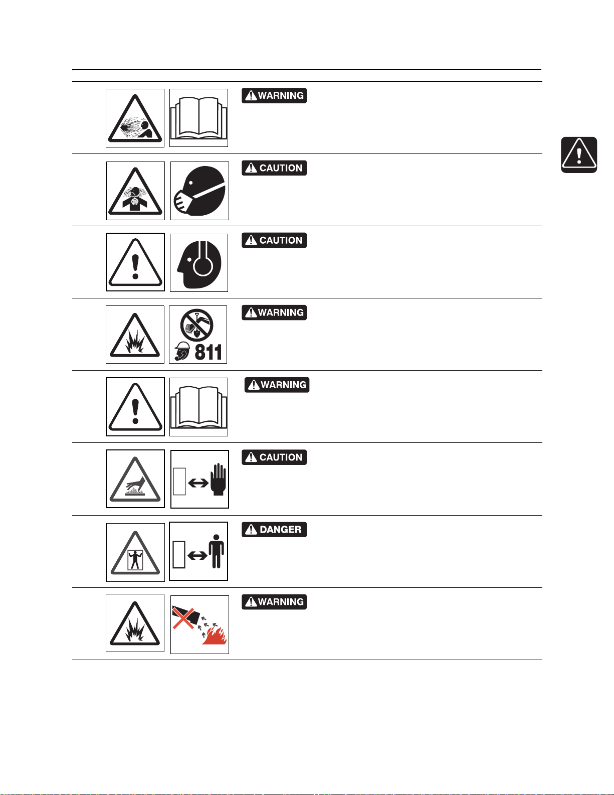
Machine Safety Alerts
Machine Safety Alerts
275-146
• Secure equipment and accessories with chain and binder.
• Check brakes and lights prior to use.
1
2
• Use proper size coupler.
• Maintain adequate distan ce for stopping and passing vehicles.
• Block wheels when parked.
• Check tire condition and inflation frequently.
• Failure to follow these rules may result in personal injury.
Lift point. See Tra nsport chapter for more information.
274-442
CMW
®
MV800 Operator’s Manual Safety - 17
Machine Safety Alerts
Contents under pressure. Relieve pressure b efore
3
opening. Death or injury could occur.
Use breathing protection when exposed to silica
dust.
4
270-4952
Exposure to high noise levels may cause hearing
5
loss. Wear hearing protection.
Jobsite hazards could cause death or serious
6
injury. Use correct equipment and work methods. Use and maintain
proper safety equipment.
274-050; 274-724 (2P)
270-2732
700-009 (2-P)
7
8
9
10
Read operator’s manual. Know how to use all
controls. Your safety is at stake.
273-475
Hot parts may cause burns. Do not touch until cool
or wear gloves.
275-355 (2-P), 273-423 (2-P)
Confined space will cause suffocation. Use proper
procedures for entering or stay away.
273-200
Fire or explosion possible. Do not vacuum
flammable or combustible substances.
273-483
CMW
®

Safety - 18 MV800 Operator’s Manual
Machine Safety Alerts
Vacuum can suffocate. Keep hose end away from
face.
11
12
13
14
273-205
Pressurized fluid or air could pierce skin and cause
severe injury. Refer to operator’s manual for proper use.
Crushing weight could cause
death or serious injury. Stay away.
275-326
Moving parts could cut off hand or foot. Stay away.
275-184
270-6035
15
Crushing weight. Place cylinder lock on extended
cylinder and secure.
273-231, 273-413
CMW
®

MV800 Operator’s Manual Controls - 19
Controls
Chapter Contents
Engine . . . . . . . . . . . . . . . . . . . . . . . . . . . . . . . . . . . 20
Operator’s Station . . . . . . . . . . . . . . . . . . . . . . . . . 21
Machine . . . . . . . . . . . . . . . . . . . . . . . . . . . . . . . . . . 24
CMW
®
Controls - 20 MV800 Operator’s Manual
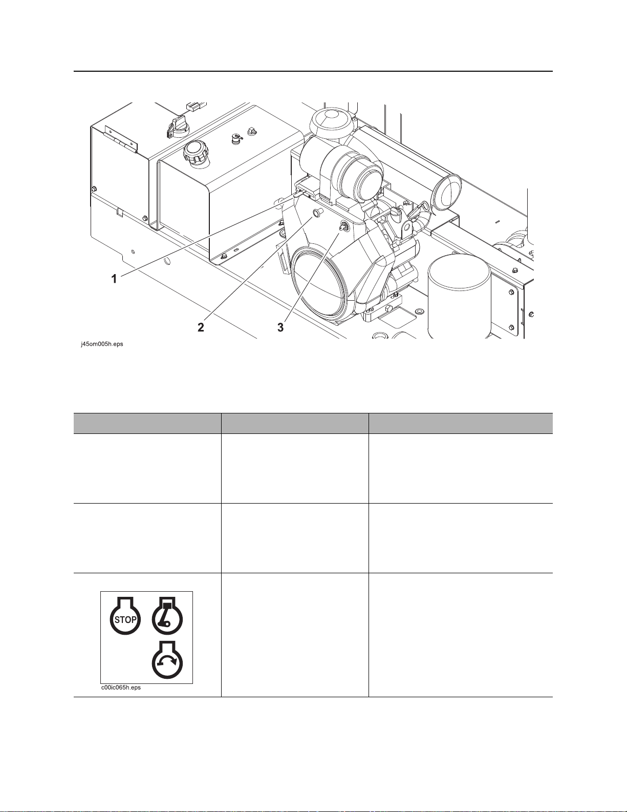
Engine
Engine
1. Throttle
2. Choke
Item Description Notes
1. Throttle To increase engine speed,
move to right.
To decrease engine speed,
move to left.
2. Choke To help start cold engine, pull
knob.
When engine has warmed,
push in completely.
3. Ignition switch T o star t engine, insert key and
turn clockwise.
To stop engine, turn key
counterclockwise.
3. Ignition switch
IMPORTANT: Run engine at full
throttle during operation.
IMPORTANT:
• When engine is on, blower
operates and vacuum is present
at tank inlet.
• All indicators should light briefly at
startup.
CMW
®

MV800 Operator’s Manual Controls - 21
c00ic114t.eps
Operator Station
Operator Station
1. Water pressure switch
2. Water pressure control
3. Water pressure gauge
4. Auxiliary outlet
Item Description Notes
1. Water pressure switch To turn on water pump, press
top.
To turn off water pump, move
to center position.
To bypass low water
indication, press bottom.
Water pump will operate for
60 seconds.
5. Hourmeter
6. Flow direction control (optional)
7. Battery disconnect switch
8. Tethered tank control outlet
Use bypass to feed antifreeze into
system when freshwater tank is
empty. See “Add Antifreeze” on
page 56.
CMW
®
Controls - 22 MV800 Operator’s Manual
c00ic113t.eps
c00ic112t.eps
Operator Station
Item Description Notes
2. Water pressure control To increase water pressure,
turn clockwise.
To decrease water pressure,
turn counterclockwise.
3. Water pressure gauge Displays water pressure
when water pressure switch
is on and spray wand is in
use.
4. Auxiliary outlet To operate work lights or
other 12V devices, plug into
outlet.
5. Hourmeter Displays engine operating
time.
6. Flow direction control To operate in reverse flow
mode, turn counterclockwise.
To operate in vacuum mode,
turn clockwise.
Outlet has power only when ignition
switch is on.
Hourmeter runs when engine is
running.
Use these times to schedule service.
Use optional reverse flow to unload
tank contents to another tank.
Operate in reverse flow mode only
when drain/outlet valve is open.
CMW
®
MV800 Operator’s Manual Controls - 23
c00ic063t.eps
+
_
+
_
c00ic065t.eps
DOWN
c00ic064t.eps
U P
Operator Station
Item Description Notes
7. Battery disconnect
switch
8. Tethered tank control
outlet
Tethered tank control To lift and lower tank, set
To connect, turn clockwise.
To disconnect, turn
counterclockwise.
Connection for tethered tank
control.
hydraulic function switch to
the tank position, then
• To lift tank, press UP.
• To lower tank, press
DOWN.
To open and close tank door,
set hydraulic function switch
to the door position, then
IMPORTANT: Use battery disconnect
switch when servicing, welding, and
during long-term storage.
NOTICE: When opening and closing
door, stand in a position with a full
view of the door.
• To open door, press UP.
• To close door, press
DOWN.
CMW
®
Controls - 24 MV800 Operator’s Manual
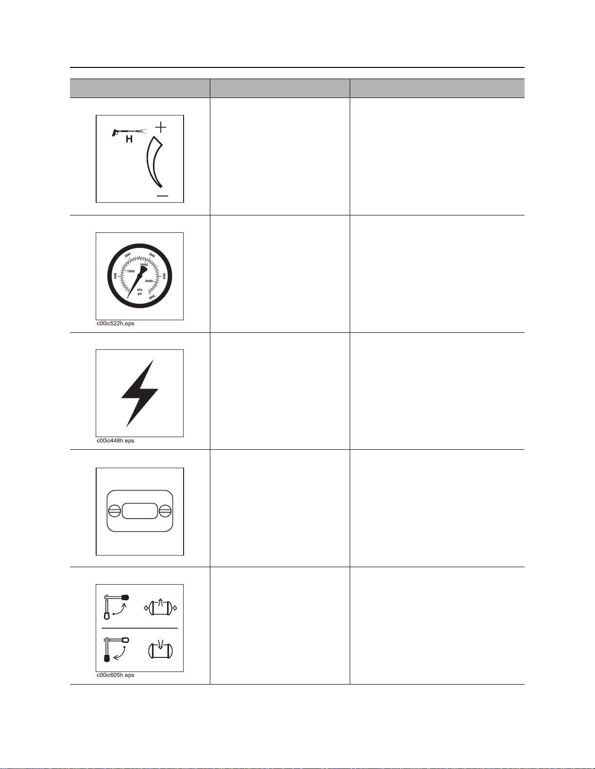
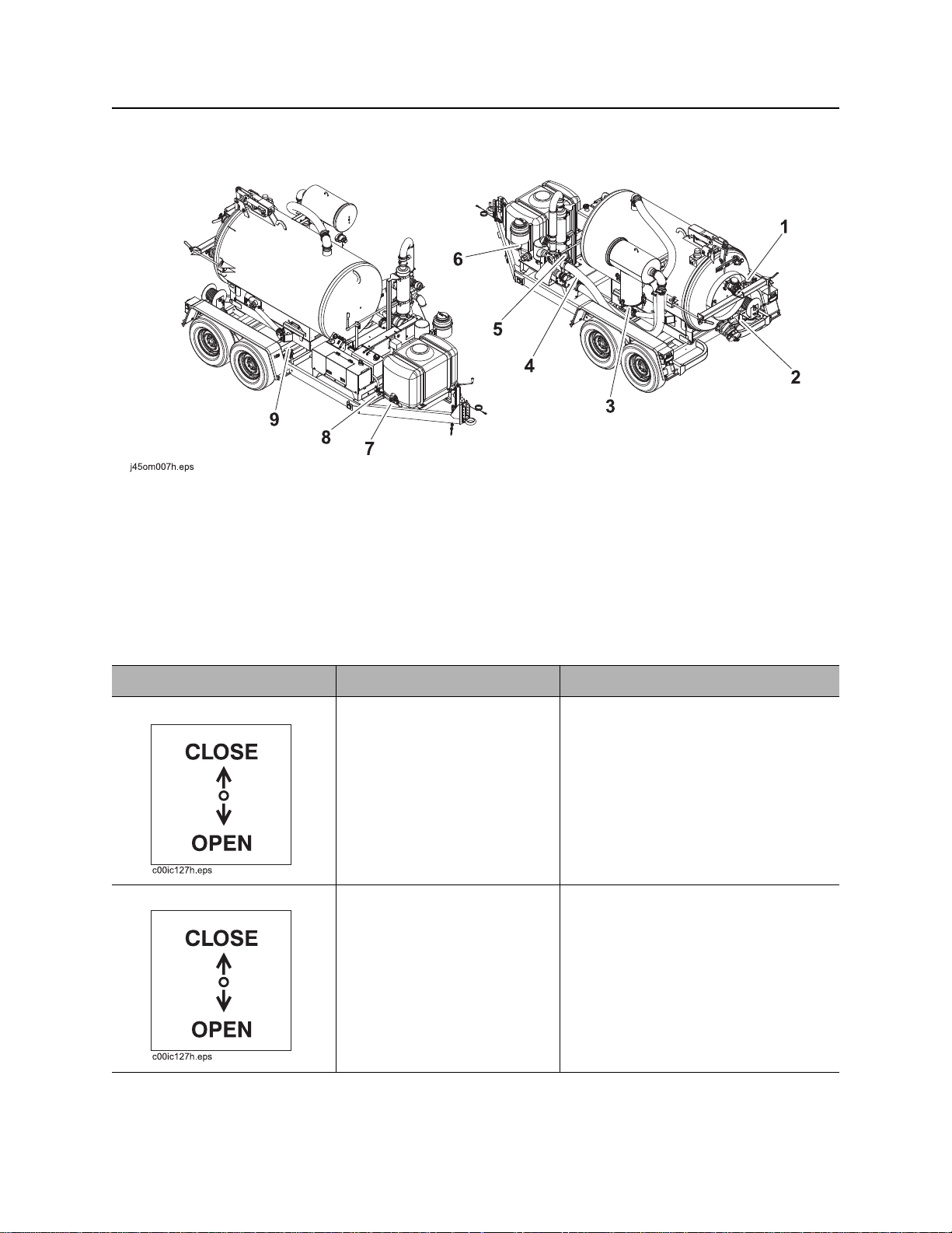
Machine
Machine
1. Inlet valve
2. Drain/Outlet valve
3. Vacuum filter drain
4. Vacuum gauge
5. Reverse flow gauge (optional)
Item Description Notes
1. Inlet valve To close valve (stop suction),
rotate up.
To open valve (start suction),
rotate down.
2. Drain/Outlet valve To drain tank, rotate down.
To close drain, rotate up.
6. Antifreeze tank supply valve (optional)
7. Water tank drain (optional)
8. Water tank supply valve (optional)
9. Hydraulic function switch (optional)
NOTICE: Do not idle engine with inlet
valve closed.
CMW
®
MV800 Operator’s Manual Controls - 25
c00ic602h.eps
c00ic604h.eps
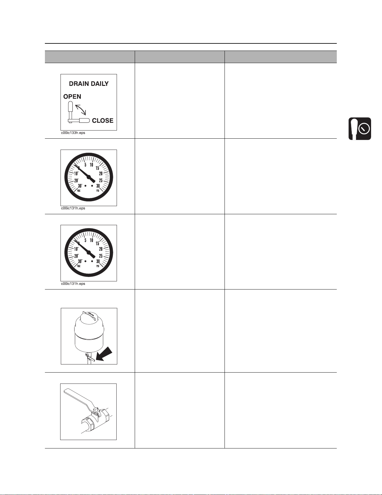
Machine
Item Description Notes
3. Vacuum filter drain To drain vacuum filter
canister, rotate up.
To close drain, rotate down.
4. Vacuum gauge Displays blower vacuum
reading in inches of mercury.
Vacuum relief valve opens
when vacuum reaches 15”
(381 mm).
5. Reverse flow gauge Displays reverse flow
pressure.
6. Antifreeze tank supply
valve
To open valve (send
antifreeze through pump and
water lance), rotate
counterclockwise.
To close valve (stop
antifreeze flow), rotate
clockwise.
7. Water tank drain To drain tank, open valve.
Close valve when tank is
empty.
IMPORTANT: Water tank supply
valve or antifreeze supply valve must
be open when pump is running or
pump will be damaged.
CMW
®
Controls - 26 MV800 Operator’s Manual
c00ic603h.eps
Machine
Item Description Notes
8. Water t ank supply valve To open valve (send water
from the water tank through
the pump and water lance),
rotate counterclockwise.
To close valve (stop water
flow), rotate clockwise.
9. Hydraulic function
switch
To lift and lower tank, push
down.
To open and close door, pull
up.
IMPORTANT: Water tank supply
valve or antifreeze supply valve must
be open when pump is running or
pump will be damaged.
Only with hydraulic door option.
CMW
®

MV800 Operator’s Manual Operation Overview - 27
Operation Overview
Chapter Contents
Planning . . . . . . . . . . . . . . . . . . . . . . . . . . . . . . . . . 28
Setting Up at Jobsite . . . . . . . . . . . . . . . . . . . . . . . 28
Vacuuming . . . . . . . . . . . . . . . . . . . . . . . . . . . . . . . 28
Potholing . . . . . . . . . . . . . . . . . . . . . . . . . . . . . . . . 29
Leaving Jobsite . . . . . . . . . . . . . . . . . . . . . . . . . . . 29
Storing Equipment . . . . . . . . . . . . . . . . . . . . . . . . . 29
CMW
®

Operation Overview - 28 MV800 Operator’s Manual
Planning
Planning
1. Gather information about jobsite (page 32).
2. Inspect jobsite (page 33).
3. Check supplies and prepare equipment (page 35).
Setting Up at Jobsite
1. Prepare jobsite (page 34).
2. Leave unit hitched to towing vehicle or properly stabilized if trailer-mounted unit.
3. Block trailer wheels if trailer-mounted unit.
Vacuuming
1. Connect hoses (page 42).
2. Start unit (page 44).
3. Remove debris (page 45).
4. Disconnect hoses.
5. Drain tank (page 48) or unload to another tank (page 50).
CMW
®

MV800 Operator’s Manual Operation Overview - 29
Potholing
Potholing
1. Connect hoses (page 42).
2. Start unit (page 42).
3. Pothole (page 46).
4. Disconnect hoses.
5. Drain tank (page 48).
Leaving Jobsite
1. Rinse unit and tools (page 57).
2. Stow tools (page 57).
Storing Equipment
1. For cold weather storage, antifreeze vacuum excavation unit (page 56).
2. For long-term storage, disconnect battery disconnect switch (page 22).
CMW
®

Operation Overview - 30 MV800 Operator’s Manual
Storing Equipment
CMW
®

MV800 Operator’s Manual Prepare - 31
Prep are
Chapter Contents
Gather Information . . . . . . . . . . . . . . . . . . . . . . . . . 32
• Arrange for Traffic Control . . . . . . . . . . . . . . . . . . . . . . . . . . . . . . . . . . .32
• Prepare for Working Near Existing Utilities . . . . . . . . . . . . . . . . . . . . . .32
• Plan for Emergency Services . . . . . . . . . . . . . . . . . . . . . . . . . . . . . . . . .32
Inspect Jobsite . . . . . . . . . . . . . . . . . . . . . . . . . . . . 33
Prepare Jobsite . . . . . . . . . . . . . . . . . . . . . . . . . . . 34
• Prepare Excavation Point . . . . . . . . . . . . . . . . . . . . . . . . . . . . . . . . . . . .34
Check Supplies and Prepare Equipment . . . . . . . 35
• Assemble Accessories . . . . . . . . . . . . . . . . . . . . . . . . . . . . . . . . . . . . . .35
• Check Supplies . . . . . . . . . . . . . . . . . . . . . . . . . . . . . . . . . . . . . . . . . . .35
• Prepare Equipment . . . . . . . . . . . . . . . . . . . . . . . . . . . . . . . . . . . . . . . .36
CMW
®

Prepare - 32 MV800 Operator’s Manual
Gather Information
Gather Information
A successful job begins before the excavation. The first step in planning is reviewing information already
available about the job and jobsite.
Arrange for Traffic Control
If working near a road or other traffic area, contact local authorities about safety procedures and
regulations.
Prepare for Working Near Existing Utilities
If jobsite may contain electrical lines, wear protective boots and gloves meeting the following standards:
• Boots must have high tops and meet th e electric hazard protection requirements of ASTM F2413 or
ASTM F1117, when tested at 14,000 volts. Tuck legs of pants completely inside boots.
• Gloves must have 17,000 AC maximum use voltage, according to ASTM spec ifica tio n D12 0.
If working around higher voltage, use gloves and boots with appropriately higher ratings.
Plan for Emergency Services
Have the telephone numbers for local emergency and medical facilities on hand. Check that you will have
access to a telephone.
CMW
®

MV800 Operator’s Manual Prepare - 33
Inspect Jobsite
Inspect Jobsite
• Follow U.S. Department of Labor regulations on excavating and trenching (Part 1926, Subpar t P) and
other similar regulations.
• Contact your local One-Call (811 in USA) or the One-Call referral number (888-258-0808 in USA and
Canada) to have underground utilities located before working. Also contact any utilities that do not
participate in the One-Call service.
• Inspect jobsite and perimeter for evidence of underground hazards, such as:
– “Buried utility” notices
– Utility facilities without overhead lines
– Gas or water meters
– Junction boxes
– Drop boxes
– Light poles
– Manhole covers
– Sunken ground
• Mark location of all buried utilities and obstructions.
CMW
®

Prepare - 34 MV800 Operator’s Manual
Prepare Jobsite
Prepare Jobsite
Jobsite hazards could cause death or serious injury. Use
correct equipment and work methods. Use and maintain proper safety
equipment.
To help avoid injury:
• Classify jobsite as electric if jobsite classification is in question or if the possibility of unmarked
electric utilities exists.
• Expose lines by hand before digging.Cutting high voltage cable can cause electrocution.
• All vegetation near operator’s station must be removed. Conta ct with trees, shrubs, or weeds during
electrical strike could result in electrocution.
Prepare Excavation Point
274-050
• Clear the area to be excavated. Remove rocks or branches too large for vacuum hose.
• If excavating fluids while drill string is moving, clear area of trees, shrubs, and weeds.
• Select a solid area to stand on while excavating.
CMW
®

MV800 Operator’s Manual Prepare - 35
Check Supplies and Prepare Equipment
Check Supplies and Prepare Equipment
Assemble Accessories
Fire Extinguisher
If required, mount a fire extinguisher near the power unit but away from possible points of ignition. The fire
extinguisher should always be classified for both oil and electric fires. It should meet legal and regulatory
requirements.
Lighting Kit
If you will need additional light, plug lighting kit into provided outlet. Contact your Ditch Witch® dealer for
further information.
Check Supplies
• water and additional hoses
•fuel
•keys
• spray lubricant
• personal protective equipment, such as hard hat and safety glasses
CMW
®

Prepare - 36 MV800 Operator’s Manual
Check Supplies and Prepare Equipment
Prepare Equipment
Fluid Levels
•fuel
•battery
• engine oil
• blower oil
Condition and Function
• filters (air, oil)
•belts
• blower
•tires
• hoses and valves
• couplers and fittings
• water tank
CMW
®

MV800 Operator’s Manual Transport - 37
Transport
Chapter Contents
Lift . . . . . . . . . . . . . . . . . . . . . . . . . . . . . . . . . . . . . . 38
• Points . . . . . . . . . . . . . . . . . . . . . . . . . . . . . . . . . . . . . . . . . . . . . . . . . . .38
• Procedure . . . . . . . . . . . . . . . . . . . . . . . . . . . . . . . . . . . . . . . . . . . . . . . .38
Haul . . . . . . . . . . . . . . . . . . . . . . . . . . . . . . . . . . . . . 39
• Inspect Trailer . . . . . . . . . . . . . . . . . . . . . . . . . . . . . . . . . . . . . . . . . . . .39
• Hitch Trailer . . . . . . . . . . . . . . . . . . . . . . . . . . . . . . . . . . . . . . . . . . . . . .40
• Unhitch Trailer . . . . . . . . . . . . . . . . . . . . . . . . . . . . . . . . . . . . . . . . . . . .40
CMW
®

Transport - 38 MV800 Operator’s Manual
Lift
Lift
Crushing weight could cause death or serious injury. Stay
away.
Points
Lifting points are identified by lifting decals. Lifting at other points is unsafe
and can damage machinery.
Procedure
275-326
Power Pack
Use a crane capable of supporting 1500 lb (680
kg). Attach lifting device to corners and lift as
shown.
CMW
®

MV800 Operator’s Manual Transport - 39
j04omo33t.eps
2
1
Haul
Tank
Use crane capable of supporting the 2000 lb (907 kg).
Use top lift point (1) as shown. Use end lift point (2) to
drain tank if machine is disabled.
NOTICE:
• Relieve pressure in tank before storing or
transporting.
• Only lift empty water or spoils tanks.
Haul
Crushing weight could cause death or serious injury. Stay
away.
275-326
T o help avoid injury: Do not haul or move trailer unless ta nk is fully lowered and h orizontal. Damage to
machine or injury to personnel could occur.
Inspect Trailer
• Check hitch for wear and cracks. Lubricate if needed.
• Inspect lights for cleanliness and correct operation. Inspect reflectors and replace if needed.
• Check tire pressure. Check lug nut torque with a torque wrench.
• Ensure trailer brakes are adjusted to come on in synchronization with tow vehicle brakes.
CMW
®

Transport - 40 MV800 Operator’s Manual
TrailerHitchAdjust_T9.epsTrailerHitchAdjust_T9.eps
Haul
Hitch Trailer
1. Back tow vehicle to trailer.
2. Put manual transmission into first or reverse gear or automatic transmission into park. Turn off ignition.
Set parking brake.
3. Connect trailer drawbar, lunette or coupler to
tow vehicle hitch and lock in place with lock
pin. If needed, adjust drawbar, lunette or
coupler height (shown) to level load.
4. Connect safety chains to tow vehicle chain
keepers (cross-shaped slots on bumper of
tow vehicle). Attach left chain to right side of
tow vehicle and vice versa to cradle hitch. Do
not connect to pintle hook or hitch ball.
5. Connect breakaway switch cable to tow
vehicle. Do not connect to pintle hook or hitch
ball.
6. Plug trailer electrical connector into tow
vehicle connector.
7. Use jack crank to raise jack base and stow.
8. Remove wheel blocks.
Unhitch Trailer
1. Stop tow vehicle and trailer on level ground.
2. Put manual transmission into first or reverse gear or automatic transmission into park. Turn off ignition.
Set parking brake.
3. Block trailer wheels.
4. To unhitch trailer from tow vehicle, reverse “Hitch Trailer“ steps.
CMW
®

MV800 Operator’s Manual Vacuum and Pothole - 41
Vacuum and Pothole
Chapter Contents
Connect Hoses . . . . . . . . . . . . . . . . . . . . . . . . . . . . 42
Determine Tank Fill Level . . . . . . . . . . . . . . . . . . . 43
• 800-gal Vacuum Tank on T14MV Trailer . . . . . . . . . . . . . . . . . . . . . . . .43
Start Unit . . . . . . . . . . . . . . . . . . . . . . . . . . . . . . . . . 44
• Standard Procedure . . . . . . . . . . . . . . . . . . . . . . . . . . . . . . . . . . . . . . . .44
Remove Debris . . . . . . . . . . . . . . . . . . . . . . . . . . . . 45
• Procedure . . . . . . . . . . . . . . . . . . . . . . . . . . . . . . . . . . . . . . . . . . . . . . . .45
Pothole . . . . . . . . . . . . . . . . . . . . . . . . . . . . . . . . . . 46
Drain Tank . . . . . . . . . . . . . . . . . . . . . . . . . . . . . . . . 48
Unload to Another Tank . . . . . . . . . . . . . . . . . . . . 50
Open/Close Tank Door . . . . . . . . . . . . . . . . . . . . . 52
• Standard Door . . . . . . . . . . . . . . . . . . . . . . . . . . . . . . . . . . . . . . . . . . . .52
• Hydraulic Door (Optional) . . . . . . . . . . . . . . . . . . . . . . . . . . . . . . . . . . . .53
CMW
®

Vacuum and Pothole - 42 MV800 Operator’s Manual
Connect Hoses
Connect Hoses
1. Remove vacuum hoses from storage.
2. If potholing, remove 2-in-1 potholing tool or basic potholing tool from storage.
3. Connect hoses. Secure all locking clamps.
4. Ensure drain/outlet valve is closed.
5. If potholing, connect water pressure hose.
2-in-1 Tool Basic Tool
CMW
®

MV800 Operator’s Manual Vacuum and Pothole - 43
Determine Tank Fill Level
Determine Tank Fill Level
Use these reference charts to help determine how full of various ma terials the va cuum t ank ca n be without
overloading trailer. Exceeding the maximum fill level will overload the trailer.
Never exceed the trailer capacity. You can exceed the vacuum tank lifting capacity if you drain the tank
down to the lifting capacity before lifting tank.
To use these charts, first select the appropriate table based on trailer and vacuum tank size. Next find the
material being excavated. If the material being excavated is not listed, find a material with similar density.
Then, determine the maximum fill level based on the amount of water in the water tank.
IMPORTANT: For all materials, the vacuum tank should be no more than half full when lifting the tank.
800-gal Vacuum Tank on T14MV Trailer
Material Maximum Vacuum Tank Fill
Level
Water tank fill level full (100 gal) empty (0 gal)
wood chips (dry) 100% 100%
snow (dry) 100% 100%
water 100% 100%
light weight mud (8-10 lb/gal) 100% 100%
earth (dry, loose) 100% 100%
caliche 93% 100%
earth, loam 93% 100%
medium weight mud (10-12 lb/gal) 88% 98%
limestone (crushed) 76% 84%
asphalt 72% 80%
sand (dry) 72% 80%
earth (wet, excavated) 72% 80%
heavy weight mud (12-15 lb/gal) 72% 79%
gravel (dry) 70% 78%
shale, riprap 69% 76%
sand (wet) 56% 62%
CMW
®

Vacuum and Pothole - 44 MV800 Operator’s Manual
Start Unit
Start Unit
EMERGENCY SHUTDOWN: Turn ignition switch to STOP.
Standard Procedure
1. Open tank inlet valve.
NOTICE: Avoid idling engine with inlet valve closed.
2. If equipped with reverse flow, ensure vacuum is in “vacuum” mode before starting.
3. Insert key.
4. Turn key clockwise. See page 20 for more information.
CMW
®

MV800 Operator’s Manual Vacuum and Pothole - 45
Remove Debris
Remove Debris
EMERGENCY SHUTDOWN: Turn ignition switch to STOP.
Procedure
1. Position vacuum hose in area to be excavated.
2. Start engine.
Vacuum can suffocate. Keep hose end away from
face.
273-205
Fire or explosion possible. Do not vacuum
flammable or combustible substances.
273-483
Read operator’s manual. Know how to use all
controls. Your safety is at stake.
To help avoid injury: Do not excavate hazardous or toxic materials. Unit is designed to excavate
only soil cuttings, drilling fluids, and other non-toxic waste.
3. Open inlet valve.
NOTICE: Avoid idling engine with inlet valve closed.
4. Use sight glasses to monitor debris level in tank. V acuum will shut off when tank is full but always heed
trailer and tank lifting capacities as indicated on page 43. Engine will remain running.
273-475
CMW
®

Vacuum and Pothole - 46 MV800 Operator’s Manual
Pothole
Pothole
EMERGENCY SHUTDOWN: Turn ignition switch to STOP.
1. Start engine.
Vacuum can suffocate. Keep hose end away from
face.
273-205
Fire or explosion possible. Do not vacuum
flammable or combustible substances.
273-483
2. Open inlet valve.
NOTICE: Avoid idling engine with inlet valve closed.
3. Open water tank valve.
4. Move water pump switch to on.
5. Position tool over area to be excavated and begin pothole.
Jobsite hazards could cause death or serious
injury. Use correct equipment and work methods. Use and maintain
proper safety equipment.
274-050
To help avoid injury: Do not direct water lance at overhead lines. Water conducts electricity.
2-in-1 Tool Basic Tool
• Squeeze water pressure lever to start
water pressure.
• Work pressurized water in a rocking or
circular motion to loosen and excavate soil
until hole is at the desired diameter and
depth.
• First use water lance to loosen soil.
• Work tool in a rocking or circular motion to
excavate soil.
• Use water lance and tool alternately until
hole is at the desired diameter and depth.
CMW
®

MV800 Operator’s Manual Vacuum and Pothole - 47
Pothole
6. Adjust water pressure as needed to match soil conditions and/or material of utility being exposed.
Jobsite hazards could cause death or serious injury.
Use correct equipment and work methods. Use and maintain proper
safety equipment.
To help avoid injury: Test water pressure on a sample of the utility line material to be exposed.
Adjust pressure until no damage occurs to the material. High pressure water can cut utility lines.
severe injury. Refer to operator’s manual for proper use.
Ensure that water sprays from nozzle in a fan pattern. If it does not, nozzle may be clogged and pump
will not function properly. Clean or replace nozzle as necessary .
274-050
Pressurized fluid or air could pierce skin and cause
270-6035
7. When freshwater tank is empty, stop operation and turn water pump switch to off.
NOTICE: Do not continue to operate with freshwater tank empty. Running water pump with no
water will damage pump.
CMW
®

Vacuum and Pothole - 48 MV800 Operator’s Manual
Drain Tank
Drain Tank
EMERGENCY SHUTDOWN: Turn ignition switch to STOP.
1. Ensure that unit is hitched to vehicle. See “Hitch Trailer” on page 40.
2. Haul unit to approved dumping area
Read operator’s manual. Know how to use all
controls. Your safety is at stake.
To help avoid injury:
•Do not unhitch unit from tow vehicle before or during dumping. A freestanding unit can
become unstable when tilting tank.
• Do not unlatch door with tank tilted up.
273-475
Use breathing protection when exposed to silica
dust.
270-4952
NOTICE: Do not drive with tank or door raised.
3. Open drain/outlet valve and inlet valve.
4. Allow tank to drain in the horizontal position until
tank is approximately half drained. Monitor sight
glasses.
5. When tank is half drained, start engine and run at
low idle.
6. Tilt tank up to help flush solids from tank.
7. Lower tank to the full horizontal position.
8. Close drain/outlet valve and inlet valve.
CMW
®

MV800 Operator’s Manual Vacuum and Pothole - 49
Drain Tank
9. If further draining is necessary, open tank door. See “Open/Close Tank Door” on page 52.
Crushing weight could cause death or serious
injury. Stay away.
To help avoid injury: Use tools (provided with unit) if unit must be
serviced with tank door up.
10. Tilt tank up fully. Allow tank to drain completely.
11. Connect water pressure hose to water lance.
12. Turn water pump switch on. Adjust water pressure.
13. Use water lance to thoroughly rinse inside of tank
and around door seal.
273-200
275-326
Confined space will cause suffocation. Use
proper procedures for entering or stay away.
To help avoid injury: Enter tank only if
necessary. Follow U.S. Department of Labor
guidelines for entering confined spaces.
14. Return tank to the fully lowered horizontal position.
15. Close tank door. See “Open/Close Tank Door” on page 52.
CMW
®

Vacuum and Pothole - 50 MV800 Operator’s Manual
j33om059h.eps
Unload to Another Tank
Unload to Another Tank
Optional reverse flow mode can be used to transfer vacuumed material to another tank or disposal site.
Read operator’s manual. Know how to use all controls.
Your safety is at stake.
To help avoid injury:
• Keep unit in “vacuum” mode unless pressure is needed.
• Restrain hose prior to pressurization. Unrestrained hose may cause property damage, injury or
death.
• Do not open fitting cams or valves when tank is pressurized. Fl ying debris, plugs and doors can
cause injury or death.
• Do not open tank door while tank is pressurized.
273-475
• Do not use pressure to clear clogs in vacuum hose.
IMPORTANT: Check relief valve as shown
before each use.
1. Throttle down completely and turn off engine. Securely connect transfer hose to vac tank. Ensure
drain/outlet valve on vac tank is closed.
2. Securely connect other end of transfer hose to offboard tank. Ensure inlet valve on offboard tank is
closed and tank is vented.
3. Open vac tank drain/outlet valve. Material will flow into transfer hose.
4. Open offboard tank inlet valve.
CMW
®

MV800 Operator’s Manual Vacuum and Pothole - 51
Unload to Another Tank
5. Move valve handle counterclockwise to engage “reverse flow” mode and start engine. Material will flow
into offboard tank.
6. Increase throttle as desired to transfer material.
7. When transfer is complete, throttle down completely and turn off engine. Close vac tank drain/outlet
valve.
8. Close offboard tank inlet valve and disconnect hose from offboard tank inlet valve.
9. Move handle clockwise to “vacuum” mode and turn on engine.
10. Open vac tank drain/outlet valve. Material will empty from transfer hose.
11. Close vac tank drain/outlet valve, throttle down and turn off engine.
12. Disconnect transfer hose from vac tank.
CMW
®

Vacuum and Pothole - 52 MV800 Operator’s Manual
Open/Close Tank Door
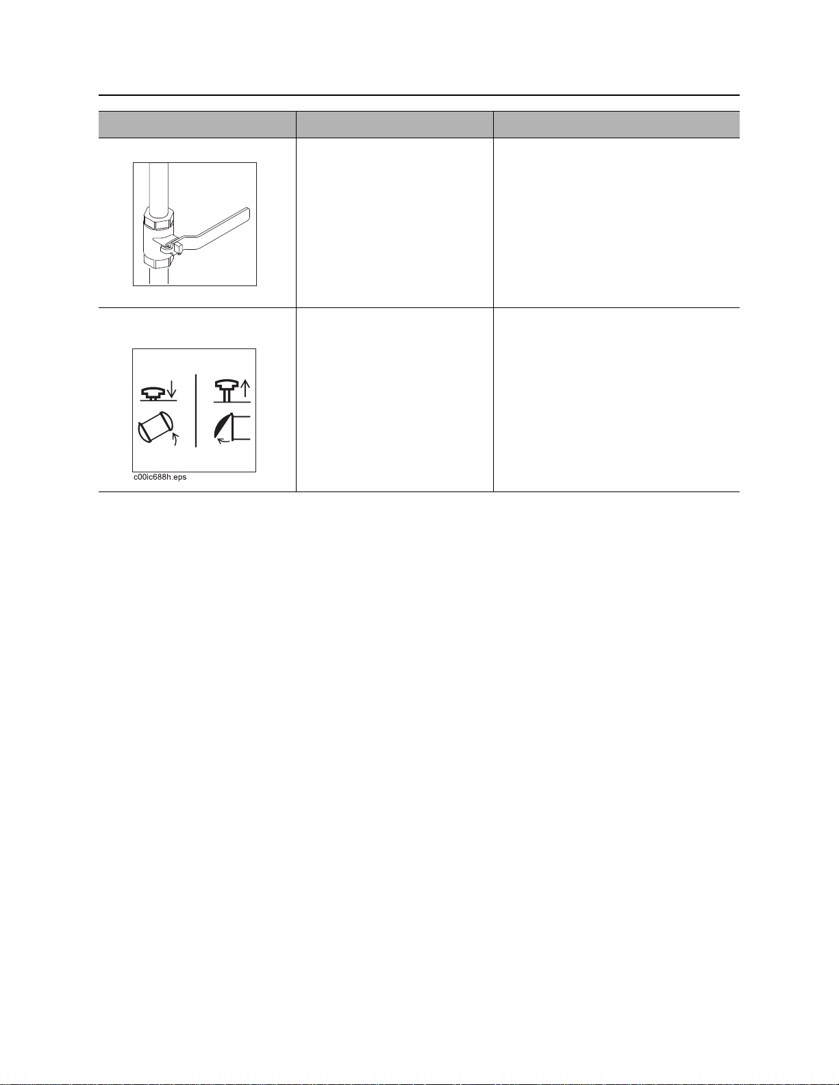
Open/Close Tank Door
Standard Door
Open
Crushing weight could cause death or serious injury. Stay
away.
To help avoid injury: Do not raise tank with door held closed only by vacuum. Door may suddenly
open and possibly injure someone.
NOTICE: Do not drive with tank or door raised.
IMPORTANT: Depressurize tank before emptying vacuum air filter canister, cleaning filter, clearing
hoses or opening any doors.
275-326
1. If using optional reverse flow mode, turn off
engine and ensure handle is down (in
“vacuum” mode).
2. If tank is tilted, lower tank fully before opening
door.
3. Open tank inlet valve.
4. Turn handles (1) coun terclockwise until door
latches are free. Rotate latches away from
tank.
Close
1. Close door.
2. Close tank inlet valve.
3. Pull stop pin (2) up and rotate door latches toward tank.
4. Turn handles (1) clockwise until door touches seal on both sides.
5. Repeat tightening until both door latches are tight.
CMW
®

MV800 Operator’s Manual Vacuum and Pothole - 53
Open/Close Tank Door
Hydraulic Door (Optional)
Open
Crushing weight could cause death or serious injury. Stay
away.
To help avoid injury: Do not raise tank with door held closed only by vacuum. Door may suddenly
open and possibly injure someone.
NOTICE: Do not drive with tank or door raised.
IMPORTANT: Depressurize tank before emptying vacuum air filter canister, cleaning filter, clearing
hoses or opening any doors.
1. If using optional reverse flow mode, turn off
engine and ensure handle is down (in
“vacuum” mode).
275-326
2. If tank is tilted, lower tank fully before opening
door.
3. Open tank inlet valve.
4. Turn handles (1) coun terclockwise until door
latches are free. Rotate latches away from
tank.
5. Set hydraulic function valve to door position.
6. Push top button on tethered control to open
door.
7. Ensure door lift latch (1) engages properly.
Door lift latch should be fully seated on pin (2).
CMW
®

Vacuum and Pothole - 54 MV800 Operator’s Manual
Open/Close Tank Door
Close
1. Fully open door to disengage optional door lift
latch (1) from pin (2). Latch cover (3) must be
down for tank door to close.
2. Close door.
3. Close tank inlet valve.
4. Pull stop pin (2) up and rotate door latches
toward tank.
5. Turn handles (1) clockwise until door tou ches
seal on both sides.
6. Repeat tightening until both door latches are
tight.
CMW
®

MV800 Operator’s Manual Complete the Job - 55
Complete the Job
Chapter Contents
Antifreeze Fluid Excavation Unit . . . . . . . . . . . . . 56
• Add Antifreeze . . . . . . . . . . . . . . . . . . . . . . . . . . . . . . . . . . . . . . . . . . . .56
• Reclaim Antifreeze . . . . . . . . . . . . . . . . . . . . . . . . . . . . . . . . . . . . . . . . .56
Rinse Equipment . . . . . . . . . . . . . . . . . . . . . . . . . . 57
Disconnect . . . . . . . . . . . . . . . . . . . . . . . . . . . . . . . 57
Stow Tools . . . . . . . . . . . . . . . . . . . . . . . . . . . . . . . 57
CMW
®

Complete the Job - 56 MV800 Operator’s Manual
Antifreeze Fluid Excavation Unit
Antifreeze Fluid Excavation Unit
Add Antifreeze
Follow these steps for overnight or long-term storage of unit during cold weather.
1. Fill antifreeze tank with a propylene-glycol based antifreeze.
2. Ensure that water tank valve is closed.
3. Open antifreeze tank valve.
4. Connect water pressure hose to water lance.
5. Start engine.
6. Move water pump switch to on. If freshwater tank is empty, move to bypass.
7. Squeeze water lance handle and run until antifreeze runs through the water lance.
8. Move water pump switch to off.
9. Close antifreeze tank supply valve.
10. Turn ignition switch to off.
11. Drain water tank completely.
Reclaim Antifreeze
1. Turn wate r pressure down.
2. Move water pump switch to on.
3. Put end of water lance in antifreeze tank.
4. Squeeze water lance handle and run until water comes out of lance.
5. Move water pump switch to off.
CMW
®

MV800 Operator’s Manual Complete the Job - 57
Rinse Equipment
Rinse Equipment
Pressurized fluid or air could pierce skin and cause
severe injury. Refer to operator’s manual for proper use.
Spray wate r onto equipmen t to remove d irt and mud. Us e water lance . Thoroughly rins e inside of tank and
around door seal
Confined space will cause suffocation. Use proper
procedures for entering or stay away.
To help avoid injury: Enter tank only if necessary. Follow U.S. Department of Labor guidelines for
entering confined spaces.
273-200
270-6035
NOTICE: Do not spray water onto operator’s console. Electrical components could be damaged. Wipe
down instead.
Disconnect
Disconnect and store the following hoses and cables (if used):
• vacuum hoses
• water pressure hose
Stow Tools
Make sure potholing tools, water lance, and other tools ar e properly stowed.
CMW
®

Complete the Job - 58 MV800 Operator’s Manual
Stow Tools
CMW
®

MV800 Operator’s Manual Service - 59
Service
Chapter Contents
Service Precautions . . . . . . . . . . . . . . . . . . . . . . . . 60
Recommended Lubricants/Service Key . . . . . . . . 62
Each Use . . . . . . . . . . . . . . . . . . . . . . . . . . . . . . . . . 64
10 Hour . . . . . . . . . . . . . . . . . . . . . . . . . . . . . . . . . . 66
50 Hour . . . . . . . . . . . . . . . . . . . . . . . . . . . . . . . . . . 74
100 Hour . . . . . . . . . . . . . . . . . . . . . . . . . . . . . . . . . 78
1000 Hour . . . . . . . . . . . . . . . . . . . . . . . . . . . . . . . . 81
2000 Hour . . . . . . . . . . . . . . . . . . . . . . . . . . . . . . . . 83
As Needed . . . . . . . . . . . . . . . . . . . . . . . . . . . . . . . 83
200 Mile . . . . . . . . . . . . . . . . . . . . . . . . . . . . . . . . . . 89
3,000 Mile. . . . . . . . . . . . . . . . . . . . . . . . . . . . . . . . . 90
12,000 Mile. . . . . . . . . . . . . . . . . . . . . . . . . . . . . . . . 91
CMW
®

Service - 60 MV800 Operator’s Manual
FX_Tank_Raised.epsFX_Tank_Raised.eps
Service Precautions
Service Precautions
Read operator’s manual. Know how to use all controls.
Your safety is at stake.
To help avoid injury:
• Unless otherwise instructed, all service should be performed with engine off.
• Refer to engine manufacturer’s manual for engine maintenance instructions.
Working Under Raised Debris Tank
Crushing weight. Place cylinder lock on extended cylinder
and secure.
273-231
273-475
1. Raise vacuum tank.
2. Remove cylinder lockout tools.
3. Place channel of lock around extended cylinders
and secure.
4. Lower vacuum tank until load is supported by
cylinder lockout tools.
CMW
®

MV800 Operator’s Manual Service - 61
Service Precautions
Working Under Raised Tank Door
Crushing weight could cause death or serious injury. Stay
away.
275-326
Standard Door
Do not work under raised tank door.
Hydraulic Door (Optional)
1. Raise tank door.
2. Ensure latch engages fully.
Welding Precaution
NOTICE: Welding can damage electronics.
• Disconnect battery to prevent damage to battery. Do not turn off battery disconnect switch with
engine running, or alternator and other electronic devices may be damaged.
• Connect welder ground clamp close to welding point and make sure no electronic components are
in the ground path.
• Always disconnect the Engine Control Unit ground connection from the frame, harness conne ctions
to the ECU, and other electronic components prior to welding on machine or attachments.
Washing Precaution
NOTICE: W ater can damage electronics. When clean ing equipment, do not spray electrical component s
with water.
CMW
®

Service - 62 MV800 Operator’s Manual
Recommended Lubricants/Service Key
Recommended Lubricants/Service Key
Item Description
GEO Gasoline engine oil meeting API service classification CF-4 or E1-96 and SAE viscosity
recommended by engine manufacturer (SAE 15W40)
SGL Synthetic gear oil (ISO 100), cmw p/n 256-044
MPG Multipurpose grease meeting ASTM D217 and NLGI 5
HTG High temperature, NLGI #2 premium grade, petroleum-based grease with high
temperature resistance and good mechanical stability
NDO 30W non-detergent oil
THF
DOT DOT 3 or 4 brake fluid
Proper lubrication and maintenance protects Ditch Witch® equipment from damage and failure. Service
intervals listed are for minimum requirements. In ex treme conditions, service machine more frequently.
Use only recommended lubricants. Fill to capacities listed in “Specifications” on page 93.
For more information on engine lubrication and maintenance, see your engine manual.
NOTICE:
• Use only genuine Ditch Witch parts, filters, approved lubricants, TJC, and approved coolants to
maintain warranty.
• Use the “Service Record” on page 101 to record all required service to your machine.
Tractor hydraulic fluid, similar to Phillips 66
®
Hydraulic Fluid, Texaco
Check level of fluid or lubricant Check condition
Filter Change, replace, adjust, service or
TDH Oil, or equivalent.
®
HG, Mobilfluid® 423, Chevron® Tractor
test
CMW
®

MV800 Operator’s Manual Service - 63
-20
20
40
60
80 100
0
F
C
-30 -20
10 0 10 20 30 40
SAE 10W-30
SAE 5W-30
Synthetic SAE 5W-30
SAE 30
j32om079t.eps
Temperature range anticipated before next oil change
Recommended Lubricants/Service Key
Engine Oil Temperature Chart
IMPORTANT: If temperature is below 40°F (4°C), using SAE 30 will result in hard starting. If
temperature is above 80°F (27°C), using 10W-30 can cause increased oil consumption. Check oil level
more frequently.
CMW
®

Service - 64 MV800 Operator’s Manual
Each Use
Each Use
Location Task Notes
Trailer Check torque of hitch bolts and verify proper hitch
height
Check tire pressure and lug nut torque 80 psi (5.5 bar);
Check lights and reflectors
Trailer
Check Hitch Bolts and Verify Proper
Hitch Height
Check that trailer hitch bolts are properly
tightened. Tighten bolts to 160 ft•lb (217 N•m).
Verify that hitch is at the proper height to avoid
adding excess load on axle and wheels.
160 ft•lb (217 N•m)
90-120 ft•lb (122-163 N•m)
Check Trailer Tire Pressure and
Lug Nut Torque
Check tire pressure (2) and lug nut (1) torque.
See below for correct pressure and torque.
Pressure Torque
80 psi (5.5 bar) 90-120 ft•lb (122-163 N•m)
®
CMW

MV800 Operator’s Manual Service - 65
Each Use
Check Trailer Lights and Reflectors
Check lights and reflectors for correct operation
and cleanliness.
CMW
®

Service - 66 MV800 Operator’s Manual
10 Hour
10 Hour
Location Task Notes
VACUUM
SYSTEM
DEBRIS
TANK
Check engine air filter service indicator
Check engine oil level GEO
Check hydraulic hoses
Check hydraulic fluid level THF
Check blower oil level SGL
Check blower belt tension
Check water pump oil level NDO
Clean water pump filter
Check tension of water pump belts
Clean vacuum air filter
Check spray nozzle
Drain vacuum air filter canister
Check strobe light
Check vacuum tank door seals/fittings
Check tank deflector
CMW
®

MV800 Operator’s Manual Service - 67
10 Hour
Vacuum System
Check Engine Air Filter
Check air filter every 10 hours. Press dust ejector
valve to release dust. Change air filter elements
when air filter restriction indicator (1) reache s the
red zone.
NOTICE: Only open the air filter canister when
air restriction is indicated. Change the elements,
do not attempt to clean them.
• Compressed air or water may damage filter
element.
• Tapping filter elements to loosen dirt may
damage the element.
.To change:
1. Remove air filter cover and remove element.
2. Wipe inside of housing and wash cover.
3. Insert new element.
4. Replace cover.
Check Engine Oil Level
While engine oil is warm, check oil level at dipstick
(2) every 10 hours. Add GEO at fill (1) as necessary
to keep oil level at highest line on dipstick.
CMW
®

Service - 68 MV800 Operator’s Manual
10 Hour
Check Hydraulic Hoses
Pressurized fluid or air could pierce skin and cause severe
injury. Refer to operator’s manual for proper use.
To help avoid injury:
• Before disconnecting a hydraulic line, turn engine off and operate all controls to relieve pressure.
Lower, block, or support any raised component with a hoist. Cover connection with heavy cloth and
loosen connector nut slightly to relieve residual pressure. Catch all fluid in a container.
• Before using system, check that all connections are tight and all lines are undamaged.
• Use a piece of cardboard or wood, rather than hands, to search for leaks.
• Wear protective clothing, including gloves and eye protection.
• If you are injured, seek immediate medical attention from a doctor familiar with this type of injury.
270-6035
Check hydraulic hoses for leaks every 10 hours.
CMW
®

MV800 Operator’s Manual Service - 69
10 Hour
Check Hydraulic Fluid Level
Check hydraulic fluid level every 10 hours. Maintain
fluid level at 3/4 tank when engine is off and fluid is
cool. Add THF at hydraulic fluid fill (shown) as
necessary.
Check Blower Oil Level
With frame level, check blower oil at sight glass
(3) every 10 hours. Add SGL at fill (2) as
necessary to maintain oil level at halfway point on
sight glass (3). Do not overfill.
Check Blower Belt Tension
Check belt every 10 hours for correct tension,
damage or wear. Idler pulley tensioner should be
set to 70 lb of force. Verify that the indication
marks on tensioner are in the same position as
initially set, or apply 10 lb of force to the belt and
check that deflection is .25-.375” (6-10 mm).
CMW
®

Service - 70 MV800 Operator’s Manual
10 Hour
Check Water Pump Oil Level
With frame level, check water pump oil at sight
glass (2) every 10 hours. Add NDO at fill (1) as
necessary to keep oil at halfway mark on sight
glass.
Clean Water Pump Filter
Clean water pump filter every 10 hours and
replace as needed.
1. Open filter housing.
2. Remove element and rinse housing
thoroughly with water.
3. Inspect element for signs of collapse and for
brittle or broken rubber seals on the ends of
the element. Replace as needed. See
page 83.
4. Replace element and close filter housing.
Check Water Pump Belt Tension
Check belt every 10 hours for correct tension,
®
damage or wear. Contact your Ditch Witch
dealer for adjustment or belt replacement.
To check
1. Turn ignition to STOP and remove key.
2. Apply moderate thumb pressure to belt
between pulleys.
3. Belt is properly tensioned when deflection is
.125-.25” (3-6 mm).
CMW
®

MV800 Operator’s Manual Service - 71
10 Hour
Clean Vacuum Air Filter
Use breathing
protection when
exposed to silica
dust.
270-4952
Clean filter every 10 hours or as needed.
To clean filter:
1. Remove filter from canister.
2. Run low pressure water into inside of filter.
NOTICE: Do not use high pressure water to clean filter. Filter will be damaged.
3. Allow filter to dry completely before returning to canister.
Check Spray Nozzle
Check spray nozzle every 10 hours. Ensure that
water sprays from nozzle in a fan pattern. Clean
or replace nozzle as necessary.
CMW
®

Service - 72 MV800 Operator’s Manual
10 Hour
Drain Vacuum Air Filter Canister
IMPORTANT: Depressurize tank before
emptying vacuum air filter canister, cleaning
filter, clearing hoses or opening any doors.
Drain canister at drain (2) every 10 hours or when
water is visible in sight glass (1).
Debris Tank
Check Strobe Light
Check strobe light for proper function every 10
hours. When ignition is on, strobe light should be
flashing. Repair if necessary.
CMW
®

MV800 Operator’s Manual Service - 73
10 Hour
Check Vacuum Tank Door Seals and
Fittings
Check door seal every 10 hours for wear or
damage. Repair if necessary. Check for leaks
and loose fittings every 10 hours. Repair or
replace if necessary.
Check Tank Deflector
Check tank deflector every 10 hours for buildup,
wear, or damage. Clean or replace as needed.
CMW
®

Service - 74 MV800 Operator’s Manual
50 Hour
50 Hour
Location Task Notes
VACUUM
SYSTEM
DEBRIS
TANK
Change engine oil and filter Initial service, GEO
Change fuel filters Initial service
Check battery
Check water pressure hoses
Check vacuum relief valve
Lube blower bearings
Change water pump oil Initial service, NDO
Lube tank pivot pins
CMW
®

MV800 Operator’s Manual Service - 75
50 Hour
Vacuum System
Change Engine Oil and Filter
(Initial Service)
Change engine oil and filter after 50 hours, and
every 100 hours thereafter. Drain oil (4), change
filter (3), and add 2.5 qt (2.3 L) of GEO at fill (2).
IMPORTANT: Use oil spec ified in temperature
chart found in “Recommended Lubricants/
Service Key” on page 62.
Change Fuel Filter (Initial)
Replace filter after the first 50 hours of operation,
and every 100 hours thereafter.
1. Remove filter.
2. Install new filter. Apply fuel oil thinly over the
gasket and hand-tighten.
CMW
®

Service - 76 MV800 Operator’s Manual
50 Hour
Check Battery
Keep battery clean and free of corrosion. Apply
coat of grease to cable clamps after cleaning.
In cold weather, battery loses some starting ability.
Closely watch voltmeter for signs of battery
discharge.
If battery will not hold charge, see your Ditch
®
Witch
dealer for replacement battery.
IMPORTANT: Use battery disconnect switch
when servicing, welding, and during long-term
storage.
Check Water Pressure Hoses
Check hoses every 50 hours for wear or damage.
Replace as necessary.
Check Vacuum Relief Valve
Check relief valve for proper operation every 50
hours. To check:
1. Ensure that vacuum inlet valve and drain
valve are both closed.
2. Start engine. Vacuum will start to build.
3. When vacuum goes over relief, check for
suction at the bottom of the relief air filter.
4. If suction is not present, stop engine and
change relief valve.
®
CMW

MV800 Operator’s Manual Service - 77
50 Hour
Lube Blower Bearings
Wipe two zerks clean and lube every 50 hours
with HTG. Inject grease into zerk until clean
grease comes out of relief fittings.
NOTICE: Do not inject grease too quickly.
Drive shaft seal damage could occur.
Change Water Pump Oil
Change oil after the first 50 hours of operation
and every 100 hours thereafter. Change oil more
frequently if working in dusty conditions.
• Drain at drain plug (3) while oil is warm.
• Add NDO at fill (1) until oil is at halfway mark
on sight glass (2).
Debris Tank
Lube Tank Pivot Pins
Lube two pins every 50 hours with MPG.
CMW
®

Service - 78 MV800 Operator’s Manual
100 Hour
100 Hour
Location Task Notes
VACUUM
SYSTEM
Change engine oil and filter GEO
Change fuel filters
Change blower oil initial service, SGL
Change hydraulic fluid DC unit initial service, THF
Change water pump oil NDO
Vacuum System
Change Engine Oil and Filter
(Regular Service)
Change engine oil and filter every 100 ho urs. Dr ain
oil (4), change filter (3), and add 2.5 qt (2.3 L) of
GEO at fill (2).
IMPORTANT: Use oil spec ified in temperature
chart found in “Recommended Lubricants/
Service Key” on page 62.
CMW
®

MV800 Operator’s Manual Service - 79
100 Hour
Change Fuel Filter
Replace filter every 100 hours.
1. Remove filter.
2. Install new filter. Apply fuel oil thinly over the
gasket and hand-tighten.
Change Blower Oil
Change oil after the first 100 hours of operation,
and every 1000 hours thereafter. Change oil more
frequently if working in dusty conditions.
• Drain at drain plug (4) while oil is warm.
• Add SGL at fill (2) until oil is at halfway point
on sight glass (3).
CMW
®

Service - 80 MV800 Operator’s Manual
100 Hour
Change Hydraulic Fluid
Change hydraulic fluid after the first 100 hours, and
every 1000 hours thereafter. Drain hydraulic fluid
(2), add THF at hydraulic fluid fill (1) and check
level.
Change Water Pump Oil
Change oil after the first 25 hours of operation
and every 100 hours thereafter. Change oil more
frequently if working in dusty conditions.
• Drain at drain plug (3) while oil is warm.
• Add NDO at fill (1) until oil is at halfway mark
on sight glass (2).
CMW
®

MV800 Operator’s Manual Service - 81
1000 Hour
1000 Hour
Location Task Notes
VACUUM
SYSTEM
Change blower oil SGL
Change hydraulic fluid THF
Vacuum System
Change Blower Oil
Change oil every 1000 hours. Change oil more
frequently if working in dusty conditions.
• Drain at drain plug (4) while oil is warm.
• Add SGL at fill (2) until oil is at halfway point
on sight glass (3).
Change Hydraulic Fluid
Change hydraulic fluid every 1000 hours. Drain
hydraulic fluid (2), add THF at hydraulic fluid fill (1)
and check level.
CMW
®

Service - 82 MV800 Operator’s Manual
2000 Hour
2000 Hour
Location Task Notes
VACUUM
SYSTEM
Replace water pump belts
Replace blower belt
Vacuum System
Replace Water Pump Belts
Replace belt every 2000 hours.
Replace Blower Belt
Replace belt every 2000 hours.
CMW
®

MV800 Operator’s Manual Service - 83
As Needed
As Needed
Location Task Notes
VACUUM
SYSTEM
DEBRIS
TANK
Change water pump filter
Lube blower for longterm storage
Change blower relief air filter
Check battery
Clean primary shutoff valve
Vacuum System
Change Water Pump Filter
1. Open filter housing.
2. Remove element and rinse housing
thoroughly with clean water.
3. Install new element and close filter housing.
Lube Blower for Long-term Storage
Lubricate blower before long-term storage to help
prevent rust and seizing.
1. Remove filter.
2. Start engine.
3. Spray light oil into port and ru n unit for 1-2
minutes.
4. Turn off engine.
CMW
®

Service - 84 MV800 Operator’s Manual
As Needed
Change Blower Relief Air Filter
Check air filter whenever vacuum gauge goes
over 16” (406 mm) of mercury. Change as
needed.
NOTICE: Operating system above 16” (406
mm) of mercury may result in blower damage.
1. Remove clamp.
2. Remove filter and discard.
3. Install new filter .
4. Replace clamp.
Lube Reverse Flow 4-Way Valve
Lube reverse flow 4-way valve at zerk (shown)
with MPG as needed. Also open left access panel
of power unit and lube zerk on other side of valve.
CMW
®

MV800 Operator’s Manual Service - 85
As Needed
Check Battery
Check battery as needed. Keep battery clean and
terminals free of corrosion.
To clean:
1. Turn battery disconnect switch, if equipped, to
the off position.
2. Ensure that no ignition sources are near
batteries.
3. Loosen and remove battery cable clamps
carefully, negative (-) cable first.
4. Clean cable clamps and terminals to remove
dull glaze.
5. Check for signs of internal corrosion in cables.
6. Apply MPG to terminals after cleaning to reduce corrosion.
7. Connect battery cable clamps, positive (+) cable first.
8. Tighten any loose connections.
9. Ensure that battery tiedowns are secure.
10. Turn battery disconnect switch to the on position.
Explosion possible. Serious injury or equipment damage could occur.
Follow directions carefully .
To help avoid injury: Do not create sparks and do not short across battery terminals for
any reason.
CMW
®

Service - 86 MV800 Operator’s Manual
As Needed
Charge Battery
Explosion possible. Serious injury or equipment damage could occur.
Follow directions carefully.
To help avoid injury:
• Use a single 12V maximum source for charging. Do not connect to rapid chargers or dual batteries.
• Use caution and wear personal protective equipment such as safety eyewear, when charging or
cleaning battery.
• Keep sparks, flames, and any ignition source away from batteries at all times. Internal contents are
extremely hazardous. Leaking fluid is corrosive. Battery may be explosive at higher temperatures.
• NEVER lean over battery when making connections.
• Do not allow vehicles to touch when charging.
• Do not attempt to charge a battery that is leaking, bulging, heavily corroded, frozen, or otherwise
damaged.
• NEVER short-circuit battery terminals for any reason or strike battery posts or cable terminals.
• Refer to MSDS for additional information regarding this battery.
Before You Start
Electronic components can be easily damaged by electrical surges. Jump starting can dam age electronics
and electrical systems, and is not recommended. Try to charge the battery instead. Use quality large
diameter jumper cables capable of carrying hig h currents ( 400 amps or more). Cheap ca bles may not allow
enough current flow to charge a dead/discharged battery.
Read all steps thoroughly and review illustration before performing procedure.
CMW
®

MV800 Operator’s Manual Service - 87
As Needed
Charging Procedure (Engine Off)
1. Park service vehicle close to disabled equipment but do not allow vehicles to touch. Engage parking
brake in both vehicles.
2. Turn the igni tion switch to the OFF position in both ve hicles, and turn off all electrical loads. Disconnect
the machine controller.
3. Inspect battery in disabled vehicle (B) for signs of cracking, bulging, leaking, or other damage.
Connect red positive (+) jumper cable clamp to positive (+) post (2) o f batter y in disab led vehicle fir st.
IMPORTANT: Some equipment may have a positive jumper cable terminal (1) located externally.
If so equipped, connect red positive (+) jumper cable clamp to terminal.
4. Connect the other red positive (+) jumper cable clamp to positive (+) post of battery (A) in the service
vehicle.
5. Connect black negative (-) cable clamp to negative (-) post of battery (A) in service vehicle.
6. Connect the other black negative (-) cable clamp to the engine or frame ground on the disabled
vehicle, at least 12” (305 mm) from the failed battery, as shown.
7. Operate service vehicle engine at 1500-2000 rpm for a few minutes to build an electrical charge in the
failed battery.
8. Stop engine in service vehicle.
9. Remove jumper cables from the service vehicle, black negative (-) clamp first. Do not allow clamps to
touch.
10. Remove black negative (-) cable clamp from the disabled engine or frame ground first.
11. Remove red positive (+) cable clamp from the disabled vehicle positive (+) battery post last.
12. Reconnect machine controller and try to start disabled vehicle.
If the disabled vehicle did not start, check for loose or corroded battery cable connectio ns. Poor
connections will prevent current from charging the failed battery. Clean terminals and posts if necessary
and repeat steps above.
CMW
®

Service - 88 MV800 Operator’s Manual
As Needed
Debris Tank
Clean Primary Shut-off Valve
Clean primary shut-off valve as needed. Replace
primary shut-off valve as needed.
To clean:
1. Open tank door. See “Drain T ank” on p age 48.
2. Spray valve housing inside vacuum tank with
high-pressure water.
3. Store water pressure hose.
4. Close tank door. See “Drain Tank” on
page 48.
To remove:
1. Remove nuts and bolts (1).
2. Remove cover (2).
3. Remove ball (3).
4. Clean ball and housing with high-pressure water.
5. Replace ball and housing.
6. Install cover and secure with nuts and bolts.
CMW
®

MV800 Operator’s Manual Service - 89
200 Mile
200 Mile
Trailer
Adjust Electric Brakes (Initial)
Adjust brakes after 200 miles (320 km).
1. Place adequate jack stands under frame rails
and remove wheels.
2. Remove cover from adjusting slot on bottom
of backing plate.
3. Rotate adjuster starwheel with screwdriver or
brake spoon to expand brake shoes. Adjust
until drum is very difficult to turn by hand.
4. Rotate starwheel the other direction until drum
turns with slight drag.
5. Replace adjusting slot cover and replace
wheel.
6. Repeat procedure for all remaining brakes.
7. Remove jack stands and lower wheels to ground.
CMW
®

Service - 90 MV800 Operator’s Manual
3000 Mile
3000 Mile
Trailer
Adjust Electric Brakes
Adjust brakes every 3000 miles (5000 km).
1. Place adequate jack stands under frame rails
and remove wheels.
2. Remove cover from adjusting slot on bottom
of backing plate.
3. Rotate adjuster starwheel with screwdriver or
brake spoon to expand brake shoes. Adjust
until drum is very difficult to turn by hand.
4. Rotate starwheel the other direction until drum
turns with slight drag.
5. Replace adjusting slot cover and replace
wheel.
6. Repeat procedure for all remaining brakes.
7. Remove jack stands and lower wheels to ground.
CMW
®

MV800 Operator’s Manual Service - 91
12,000 Mile
12,000 Mile
Location Task Notes
Trailer Inspect brake shoes and linings
Adjust and lubricate bearings
Trailer
Inspect Brake Shoes and Linings
Inspect shoes and linings every 12 months or
12,000 miles (20 000 km) for wear. When lining is
worn to 1/16” (2 mm) or less, replace linings.
Replace shoe and lining if contaminated by oil.
CMW
®

Service - 92 MV800 Operator’s Manual
12,000 Mile
Adjust and Lubricate Bearings
1. Place adequate jack stands under frame rails
and remove wheels.
2. Unscrew grease cap (11) while holding the
hub stationary.
3. Bend locking tang (14) down from outer
spindle nut (13) and remove spindle nut (3).
4. Remove tang washer, unscrew inner spindle
nut and remove spindle washer (16).
5. Remove hub from spindle. Do not drop outer
bearing cone.
6. Pry seal (2) from hub and remove inner
bearing cone (3).
7. Inspect brake drum for excessive wear or heavy scoring.
Condition Recommended Action
Brake drum worn more than .020” (.5 mm). Remachine drum surface
Brake drum worn out of round more than .015” (.39 mm).
Brake drum has scoring and other wear greater than .090” (2.29 mm) Replace drum
8. Clean all grease from bearing cups (4,8), cones (9,3), hardware, and hub bore using suitable solvent.
Dry components with lint free cloth.
9. Inspect bearing cups and cones for pitting, spalling, and corrosion. Replace if damaged.
10. Pack all cones using an extreme pressure, water resistant lithium complex grease. Apply light coating
of grease to bearing cones.
1 1. Install the bearing and washer into the hub. Thread on the inner nut, rot ate the hub, and tighte n the nut
until the hub will not rotate. This requires a minimum of 100 ft•lb (136 N•m) of torque.
12. Loosen the nut to remove preload torque.
13. Hand tighten the nut and back it off 1/4 to 3/4 of a turn.
14. Place tang washer on spindle and bend one tang inward over the nut. This will keep the inner nut from
turning while torque is applied to the outer nut.
15. Install the outer nut. Ensure that inner nut does not turn. Bend two t angs from the tang washer over the
outer flats to secure.
16. Install cap with o-ring and plug installed. Rotate the hub and check bearing adjustment. Allowable end
play is .001-.010” (.025-.25 mm).
CMW
®

MV800 Operator’s Manual Specifications - 93
Specifications
Dimensions U.S. Metric
L Length, T14MV trailer 208 in 5.2 m
H Height 91.5 in 2.3 m
W Width 96.5 in 2.5 m
Weight: no options
Empty 4995 lb 2265 kg
Full 10,840 lb 4917 kg
Weight: suction and water unit
Empty 5590 lb 2536 kg
Full water tank, empty vac tank 6425 lb 2914 kg
Empty water tank, full (water) vac tank 11,670 lb 5294 kg
Full water tank, full (water) vac tank 12,510 lb 5675 kg
Vac Tank U.S. Metric
Capacity 730 gal 2763 L
Length 98 in 2.5 m
Diameter 52 in 1.3 m
Drain valve size 6 in 152 mm
Inlet valve size 4 in 102 mm
CMW
®

Specifications - 94 MV800 Operator’s Manual
Engine U.S. Metric
®
Briggs & Stratton
Vanguard, gasoline
Cooling medium air
Aspiration natural
Number of cylinders 2
Displacement
54.68 in
3
896 cc
Bore 3.37 in 86 mm
Stroke 3.07 in 78.5 mm
Engine manufacturer’s gross power rating (per SAE J1940) 31 hp 23.1 kW
Rated engine speed 3600 rpm 3600 rpm
Emissions compliance: EPA LSI, EU Stage II
Hydraulic system U.S. Metric
Pressure 2500 psi 172 bar
Drive type 12V DC
Tank lift cylinder size (2) 2.5 in 63.5 mm
Maximum tilt angle 45° 45°
Battery
SAE res. cap. 120 min; SAE cold crank @ 0°F (-18°C) 750A, 12V
Vacuum system U.S. Metric
Drive type belt
Displacement 543 cfm
15.3 m
3
Maximum vacuum 15 in Hg 381 mm Hg
Filter type washable polyester
Filter area
100 ft
2
9.3 m
2
Suction hose size 3 in 76 mm
®
CMW
/min

MV800 Operator’s Manual Specifications - 95
Water system U.S. Metric
Maximum pressure 3000 psi 207 bar
Flow 4 gpm 15.1 L/min
Hose reel capacity (locking) 50 ft 15.2 m
Antifreeze 50/50 water/antifreeze mix
Clutch type electric with auto de-clutch
Fluid capacities U.S. Metric
Engine oil with filter 4.2 qt 4 L
Fuel tank 6.9 gal 26.1 L
Vacuum pump 1.5 qt 1.4 L
Hydraulic reservoir 2.0 gal 7.6 L
Water pump 41 oz 1.2 L
Water tank 100 gal 379 L
Noise levels (without reverse flow)
Operator 79 dBA sound pressure per ISO 6394, at operator ear 25 ft (7.5 m) behind power unit.
Exterior 109 dBA sound power per ISO 6393.
Noise levels (with reverse flow)
Suction mode:
Operator 79 dBA sound pressure per ISO 6394, at operator ear 25 ft (7.6 m) behind power unit.
Exterior 109 dBA sound power per ISO 6393.
Reverse flow mode:
Operator 79 dBA sound pressure per ISO 6394, at operator ear 25 ft (7.5 m) behind power unit.
Exterior 107 dBA sound power per ISO 6393.
CMW
®

Specifications - 96 MV800 Operator’s Manual
T14MV Trailer U.S. Metric
Dimensions
Clearance (at jack foot pad) 13 in 330 mm
Adj. coupler height 18-26 in 457-660 mm
Width between fenders 76 in 1.9 m
Width outside fenders 96 in 2.4 m
General
Number of axles 2
Coupler (square mount drawbar) 3 in or 2.5 in 76 mm or 64
mm
Type of brakes electric
Lug nut torque 90-120 ft•lb 122-163 N•m
Hitch bolt torque 160 ft•lb 217 N•m
Electrical system 12V DC
Tire LT215/85R16 load range E 80 psi 5.5 bar
Load rating
Suction only
Tongue weight (empty) 645 lb 294 kg
Tongue weight (full water) 1010 lb 458 kg
Suction & Water
Tongue weight (empty) 890 lb 404 lb
Tongue weight (water full, vac empty) 1475 lb 669 lb
Tongue weight (vac full of water, water empty) 1300 lb 590 lb
Tongue weight (vac full of water, water full) 1880 lb 853 lb
GVWR (gross vehicle weight rating) 14,000 lb 6350 kg
GAWR (gross axle weight rating, each) 7000 lb 3175 kg
Load ratings for speeds up to 65 mph (104 km/h).
CMW
®

MV800 Operator’s Manual Support - 97
Procedure
Support
Procedure
Notify your dealer immediately of any malfunction or failure of Ditch Witch® equipment.
Always give model, serial number, and approximate date of your equipment purchase. This information
should be recorded and placed on file by the owner at the time of purchase.
Return damaged parts to dealer for inspection and warranty consideration if in warranty time frame.
Order genuine Ditch Witch replacement or repair parts from your authorized Ditch Witch dealer. Use of
another manufacturer's parts may void warranty consideration.
Resources
Publications
Contact your Ditch Witch dealer for publications and videos covering safety, operation, service, and repair
of your equipment.
Ditch Witch® Training
For information about on-site, individualized training, contact your Ditch Witch dealer.
CMW
®

Warranty - 98 MV800 Operator’s Manual
Warranty
Ditch Witch® Equipment and Replacement Parts
Limited Warranty Policy
Subject to the limitation and exclusions herein, free replacement parts will be provided at any authorized Ditch Witch dealership for
any Ditch Witch equipment or parts manufactured by The Charles Machine Works, Inc. (CMW) that fail due to a defect in material or
workmanship within one (1) year of first commercial use. Free labor will be provided at any authorized Ditch Witch dealership for
installation of parts under this warranty during the first year following “initial commercial” use of the serial-numbered Ditch Witch
equipment on which it is installed. The customer is responsible for transporting their equipment to an authorized Ditch Witch
dealership for all warranty work.
Exclusions from Product Warranty
• All incidental or consequential damages.
• All defects, damages, or injuries caused by misuse, abuse, improper installation, alteration, neglect, or uses other than those for
which products were intended.
• All defects, damages, or injuries caused by improper training, operation, or servicing of products in a manner inconsistent with
manufacturer’s recommendations.
• All engines and engine accessories (these are covered by original manufacturer’s warranty).
• Tires, belts, and other parts which may be subject to another manufacturer’s warranty (such warranty will be available to
purchaser).
• ALL IMPLIED WARRANTIES NOT EXPRESSLY STATED HEREIN, INCLUDING ANY WARRANTY OF FITNESS FOR A
PARTICULAR PURPOSE AND MERCHANTABILITY.
IF THE PRODUCTS ARE PURCHASED FOR COMMERCIAL PURPOSES, AS DEFINED BY THE UNIFORM COMMERCIAL
CODE, THEN THERE ARE NO WARRANTIES WHICH EXTEND BEYOND THE FACE HEREOF AND THERE ARE NO IMPLIED
WARRANTIES OF ANY KIND WHICH EXTEND TO A COMMERCIAL BUYER. ALL OTHER PROVISIONS OF THIS LIMITED
WARRANTY APPLY INCLUDING THE DUTIES IMPOSED.
Ditch Witch products have been tested to deliver acceptable performance in most conditions. This does not imply they will deliver
acceptable performance in all conditions. Therefore, to assure suitability, products should be operated under anticipated working
conditions prior to purchase.
Defects will be determined by an inspection within thirty (30) days of the date of failure of the product or part by CMW or its authorized
dealer. CMW will provide the location of its inspection facilities or its nearest authorized dealer upon inquiry. CMW reserves the right
to supply remanufactured replacements parts under this warranty as it deems appropriate.
Extended warranties are available upon request from your local Ditch Witch dealer or CMW.
Some states do not allow exclusion or limitation of incidental or consequential damages, so above limitation of exclusion may not
apply. Further, so me states do not allow exclusion of or limitation of how long an implied warranty lasts, so the above limitation may
not apply. This limited warranty gives product owner specific legal rights and the product owner may also have other rights which vary
from state to state.
For information regarding this limited warranty, contact CMW’s Product Support department, P.O. Box 66, Perry, OK 73077-0066, or
contact your local Ditch Witch dealer.
First version: 1/91; Latest version: 11/11
CMW
®

 Loading...