


MR90
Operator’s
Manual
CMW
68
®
Issue 1.0
053-2768

MR90 Operator’s Manual Overview - 1
Overview
Chapter Contents
Serial Number Location . . . . . . . . . . . . . . . . . . . . . . 2
Intended Use . . . . . . . . . . . . . . . . . . . . . . . . . . . . . . 3
Equipment Modification . . . . . . . . . . . . . . . . . . . . . . 2
Unit Components . . . . . . . . . . . . . . . . . . . . . . . . . . . 4
Operator Orientation. . . . . . . . . . . . . . . . . . . . . . . . . 3
About This Manual . . . . . . . . . . . . . . . . . . . . . . . . . . 5
• Bulleted Lists . . . . . . . . . . . . . . . . . . . . . . . . . . . . . . . . . . . . . . . . . . . . . .5
• Numbered Lists . . . . . . . . . . . . . . . . . . . . . . . . . . . . . . . . . . . . . . . . . . . .5
CMW
®

Overview - 2 MR90 Operator’s Manual
Serial Number Location
Serial Number Location
Record serial numbers and date of purchase in spaces provided. Fluid unit serial number is located as
shown.
Item
date of manufacture
date of purchase
fluid unit serial number
engine serial number
CMW
®

MR90 Operator’s Manual Overview - 3
Intended Use
Intended Use
The MR90 is a self-contained fluid handling unit capable of mixing and recycling drilling fluid and
transferring fluid under pressure to the drilling unit. It is intended for operation in ambient temperatures
from 32° to 115°F (0° to 46°C). Use in any other way is considered contrary to the intended use.
The MR90 can be used with Ditch Witch
by persons familiar with its particular characteristics and acquainted with the relevant safety procedures.
®
drilling units. It should be operated, serviced, and repaired only
Equipment Modification
This equipment was designed and built in accordance with applicable standards and regulations.
Modification of equipment could mean that it will no longer meet regulations and may not function properly
or in accordance with the operating instructions. Modification of equipment should only be made by
competent personnel possessing knowledge of applicable standards, regulations, equipment design
functionality/requirements and any required specialized testing.
CMW
®
Overview - 4 MR90 Operator’s Manual
Unit Components
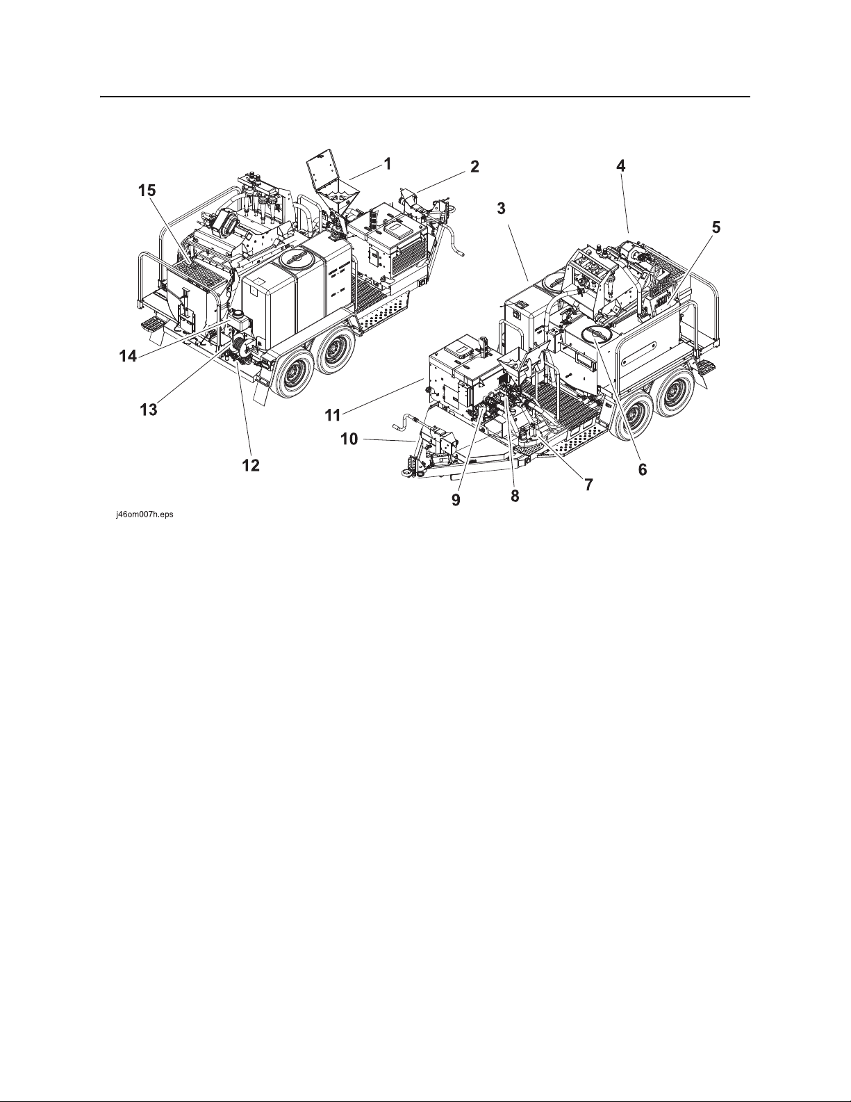
Unit Components
1. Mixing hopper
2. Hydraulic jack
3. Fresh water tank (300 gallon)
4. Shaker
5. Operator station
6. MR90 tank
7. Pit pump
8. Mix/supply pump
9. Cleaning pump
10. T14 trailer
11. FM25h power unit
12. Water pump
13. Hose reel
14. Antifreeze tank
15. Spoils hopper*
*optional
CMW
®
MR90 Operator’s Manual Overview - 5
Operator Orientation
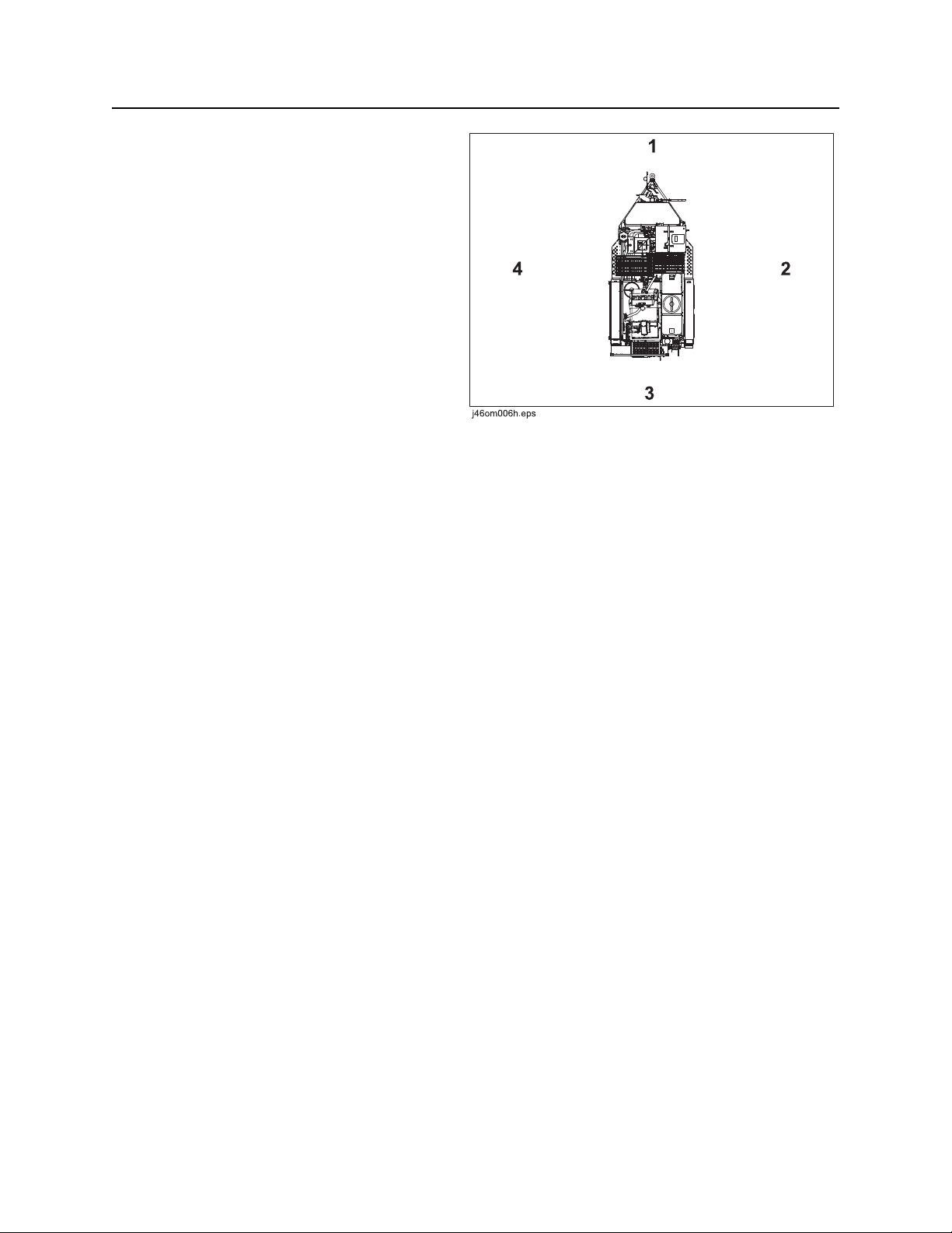
Operator Orientation
1. Front of unit
2. Right of unit
Right and left sides of machine are determined
by facing towing vehicle.
3. Rear of unit
4. Left of unit
About This Manual
This manual contains information for the proper use of this machine. See the beige Operation Overview
pages for basic operating procedures. Cross references such as “See page 50” will direct you to detailed
procedures.
Bulleted Lists
Bulleted lists provide helpful or important information or contain procedures that do not have to be
performed in a specific order.
Numbered Lists
Numbered lists contain illustration callouts or list steps that must be performed in order.
CMW
®

Overview - 6 MR90 Operator’s Manual
About This Manual
CMW
®

MR90 Operator’s Manual Foreword - 7
Reporting Safety Defects
Foreword
This manual is an important part of your equipment. It provides safety information and operation
®
instructions to help you use and maintain your Ditch Witch
Read this manual before using your equipment. Keep it with the equipmen t at all times for future reference.
If you sell your equipment, be sure to give this manual to the new owner.
If you need a replacement copy, contact your Ditch Witch dealer. If you need assistance in locating a
dealer, visit our website at www.ditchwitch.com or write to the following address:
The Charles Machine Works, Inc.
Attn: Marketing Department
PO Box 66
Perry, OK 73077-0066
USA
The descriptions and specifications in this manual are subject to change without notice. The Charles
Machine Works, Inc. reserves the right to improve equipment. Some product improvements may have
taken place after this manual was publishe d. For the latest information on Ditch Witch equipment, see your
Ditch Witch dealer.
equipment.
Thank you for buying and using Ditch Witch equipment.
Reporting Safety Defects
If you believe that your vehicle has a defect which could cau se a cr ash o r co uld ca use injury or death, you
should immediately inform the National Highway Traffic Safety Administration (NHTSA) in addition to
notifying the Product Safety Coordinator at The Charles Machine Works, Inc.
If NHTSA receives similar complaints, it may open an investigation, and if it finds that a safety defect exists
in a group of vehicles, it may order a recall and remedy campaign. However, NHTSA cannot become
involved in any individual problems between you, your Ditch Witch dealer, or The Charles Machine Works,
Inc.
To contact NHTSA you may either call the Auto Safety Hotline toll-free at 1-888-327-4236 (TT Y: 1-800424-9153), go to http://www.safercar.gov, or write to:
Administrator
NHTSA
1200 New Jersey Avenue S.E.
Washington, DC 20590
You can also obtain other information about motor vehicle safety from http://www.safercar.gov.
CMW
®

Foreword - 8 MR90 Operator’s Manual
Works, Inc.
MR90
Operator’s Manual
Issue number 1.0/OM-10/14
Part number 053-2768
Copyright 2014
by The Charles Machine Works, Inc.
, Ditch Witch, and CMW are registered trademarks of The Charles Machine
U.S. patents pending.
®
CMW

MR90 Operator’s Manual Contents - 9
Content s
Overview
machine serial number, information about the type of work this machine is designed
to perform, basic machine components, and how to use this manual
Foreword
part number, revision level, and publication date of this manual, and factory contact
information
Safety
machine safety alerts and emergency procedures
Controls
machine controls, gauges, and indicators and how to use them
Prepare
procedures for inspecting the jobsite and preparing the jobsite fo r work
Transport
procedures for lifting and hauling
Handle Fluid
procedures for mixing, recycling, and transferring fluid
1
5
9
17
29
33
37
Systems and Equipment
procedures for selecting fluid additives, determining fluid requirements and fluid
measurements, and screens
Complete the Job
procedures for rinsing and storing equipment
Service
service intervals and instructions for this machine including lubrication, replacement
of wear items, and basic maintenance
Specifications
machine specifications including weights, measurements, power ratings, and fluid
capacities
Support
the warranty policy for this machine, and procedures for obtaining warranty
consideration and training
Service Record
a record of major service performed on the machine
43
43
45
57
107
111
CMW
®

Contents - 10 MR90 Operator’s Manual
Appendix
additional information about your equipment
113
CMW
®

MR90 Operator’s Manual Safety - 11
Safety
Chapter Contents
Guidelines . . . . . . . . . . . . . . . . . . . . . . . . . . . . . . . . 12
Emergency Procedures . . . . . . . . . . . . . . . . . . . . . 13
• Electric Strike Description. . . . . . . . . . . . . . . . . . . . . . . . . . . . . . . . . . . .13
• If an Electric Line is Damaged . . . . . . . . . . . . . . . . . . . . . . . . . . . . . . . .14
• If a Gas Line is Damaged . . . . . . . . . . . . . . . . . . . . . . . . . . . . . . . . . . . .15
• If a Fiber Optic Cable is Damaged . . . . . . . . . . . . . . . . . . . . . . . . . . . . .16
• If Machine Catches on Fire. . . . . . . . . . . . . . . . . . . . . . . . . . . . . . . . . . .16
Safety Alert Classifications . . . . . . . . . . . . . . . . . . 17
Machine Safety Alerts. . . . . . . . . . . . . . . . . . . . . . . 18
CMW
®

Safety - 12 MR90 Operator’s Manual
Guidelines
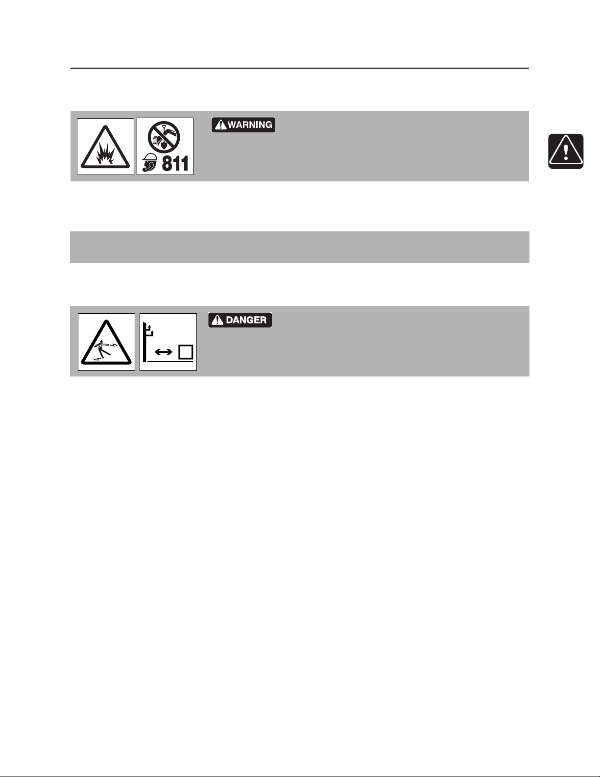
Guidelines
Follow these guidelines before operating any jobsite equipment:
• Complete proper training and read operator’s manual before using equipment.
• Contact your local One-Call (811 in USA) or the One-Call referral number (888-258-0808 in USA and
Canada) to have underground utilities located before digging. Also contact any utilities that do not
participate in the One-Call service. Mark proposed p ath with white paint prior to cont acting One- Call or
utilities.
• Classify jobsite based on its hazards and use cor rect tools and machin ery, safety equipment, and work
methods for jobsite.
• Mark jobsite clearly and keep spectators away.
• Wear personal protective equipment.
• Review jobsite hazards, safety and emergency procedures, and individual responsibilities with all
personnel before work begins. Safety videos are available from your Ditch Witch
ditchwitch.com/resources/safety .
• Replace missing or damaged safety shields and safety signs.
®
dealer or at
• Use equipment carefully. Stop operation and investigate anything that does not look or feel right.
• Do not operate unit where flammable gas may be present.
• Contact your Ditch Witch dealer if you have any question about operation, ma intenance, or equipment
use.
• Complete the equipment checklist located at www.ditchwitch.com/resources/safety.
CMW
®
MR90 Operator’s Manual Safety - 13
Emergency Procedures
Emergency Procedures
Jobsite hazards could cause death or serious injury. Use
correct equipment and work methods. Use and maintain proper safety
equipment.
Before operating any equipment, review emergency proc edures and check that all safety precau tions have
been taken.
EMERGENCY SHUTDOWN - Turn ignition switch to stop position or push remote e ngine stop button ( if
equipped).
Electric Strike Description
or serious injury. Know location of lines and stay away.
274-050
Electric shock. Contacting electric lines will cause death
When working near electric cables, remember the following:
• Electricity follows all paths to ground, not just path of least resistance.
• Pipes, hoses, and cables will conduct electricity back to all equipment.
• Low voltage current can injure or kill. Many work-related electrocutions result from contact with less
than 440 volts.
Most electric strikes are not noticeable, but indications of a strike include:
• power outage
•smoke
•explosion
• popping noises
• arcing electricity
If any of these occur, assume an electric strike has occurred.
CMW
®

Safety - 14 MR90 Operator ’s Manual
Emergency Procedures
If an Electric Line is Damaged
If you suspect an electric line has been damaged and you are on truck or trailer, DO NOT MOVE.
Remain on truck or trailer and take the following actions. The order and degree of action will depend on the
situation.
• Warn people nearby that an electric strike has occurred. Instruct them to leave the area and contact
utility.
• Do not allow anyone into area until given permission by utility company.
• Do not allow anyone to touch equipment.
If you suspect an electric line has been damaged and you are off truck or trailer, DO NOT TOUCH
EQUIPMENT. Take the following actions. The order and degree of action will depend on the situation.
• LEAVE AREA. The ground surface may be electrified so take small shuffle steps with feet close
together to reduce the hazard of being shocked from one foot to the other.
• Contact utility company to shut off power.
• Do not return to area or allow anyone into area until given permission by utility company.
CMW
®
MR90 Operator’s Manual Safety - 15
Emergency Procedures
If a Gas Line is Damaged
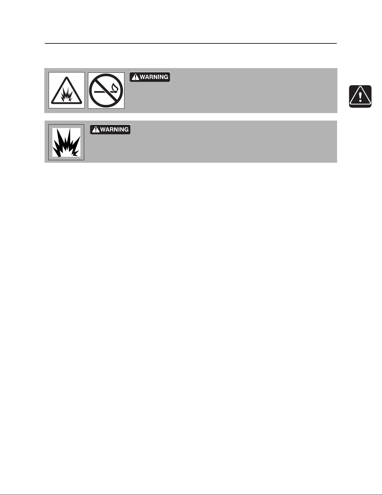
Fire or explosion possible. Fumes could ignite and cause
burns. No smoking, no flame, no spark.
Explosion possible. Serious injury or equipment damage could occur.
Follow directions carefully.
If you suspect a gas line has been damaged, take the following actions. The order and degree of action will
depend on the situation.
• Immediately shut off engine(s), if this can be done safely and quickly.
• Remove any ignition source(s), if this can be done safely and quickly.
275-419 (2P)
• Warn others that a gas line has been cut and that they should leave the area.
• Leave jobsite as quickly as possible.
• Immediately call your local emergency phone number and utility company.
• If jobsite is along street, stop traffic from driving near jobsite.
• Do not return to jobsite until given permission by emergency personnel and utility company.
CMW
®

Safety - 16 MR90 Operator ’s Manual
Emergency Procedures
If a Fiber Optic Cable is Damaged
Do not look into cut ends of fiber optic or unidentified cable. Vision damage can occur. Contact utility
company.
If Machine Catches on Fire
Perform emergency shutdown procedure and then take the following actions. The order and degree of
action will depend on the situation.
• Immediately move battery disconnect switch (if equipped and accessible) to disconnect position.
• If fire is small and fire extinguisher is available, attempt to extinguish fire.
• If fire cannot be extinguished, leave area as quickly as possible and contact emergency personnel.
CMW
®
MR90 Operator’s Manual Safety - 17
Safety Alert Classifications
Safety Alert Classifications
These classifications and the icons defined on the following pages work together to alert you to situations
which could be harmful to you, jobsite bystanders or your equipment. When you see these words and
icons in the book or on the machine, carefully read and follow all instructions. YOUR SAFETY IS AT
STAKE.
Watch for the three safety alert levels: DANGER, WARNING and CAUTION. Learn what each level
means.
indicates a hazardous situation that, if not avoided, will result in death or serious injury. This
signal word is to be limited to the most extreme situations.
indicates a hazardous situation that, if not avoided, could result in death or serious injury.
indicates a hazardous situation that, if not avoided, could result in minor or mo derate injury.
Watch for two other words: NOTICE and IMPORTANT.
NOTICE indicates information considered important, but not hazard-related (e.g., messages relating to
property damage).
IMPORTANT can help you do a better job or make your job easier in some way.
CMW
®

Safety - 18 MR90 Operator ’s Manual
Machine Safety Alerts
Machine Safety Alerts
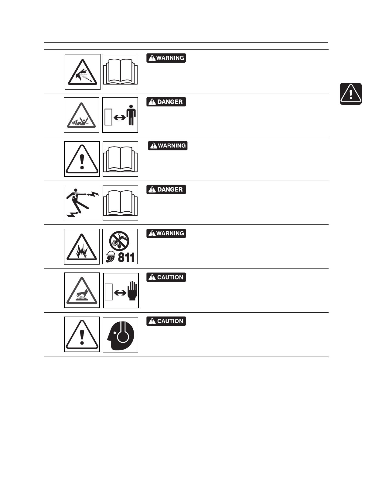
Moving parts could cut off hand o r foot. S tay away.
1
275-184, 273-437, 273-546
Tiedown location. See Transport chapter for more information.
274-318
2
Lift point. See Tra nsport chapter for more information.
274-442
3
CMW
®
MR90 Operator’s Manual Safety - 19
Machine Safety Alerts
Pressurized fluid or air could pierce skin and cause
4
severe injury. Refer to operator’s manual for proper use.
Rotating shaft will cause death or serious injury.
5
Stay away.
270-1506
Read operator’s manual. Know how to use all
6
controls. Your safety is at stake.
273-475
Electric shock will cause death or serious injury.
7
Fluid system could become electrified while connected to drilling
unit. Read operator’s manual and know emergency procedures.
273-265
270-6035
8
9
10
Jobsite hazards could cause death or serious
injury. Use correct equipment and work methods. Use and maintain
proper safety equipment.
274-050; 274-724 (2P)
Hot parts may cause burns. Do not touch until cool
or wear gloves.
275-355 (2-P), 273-423 (2-P)
Exposure to high noise levels may cause hearing
loss. Wear hearing protection.
700-009 (2-P)
CMW
®

Safety - 20 MR90 Operator ’s Manual
Machine Safety Alerts
CMW
®

MR90 Operator’s Manual Controls - 21
Controls
Chapter Contents
Power Unit . . . . . . . . . . . . . . . . . . . . . . . . . . . . . . . 22
Mixing Unit . . . . . . . . . . . . . . . . . . . . . . . . . . . . . . . 30
Recycling Unit. . . . . . . . . . . . . . . . . . . . . . . . . . . . . 33
CMW
®
Controls - 22 MR90 Operator’s Manual
Power Unit
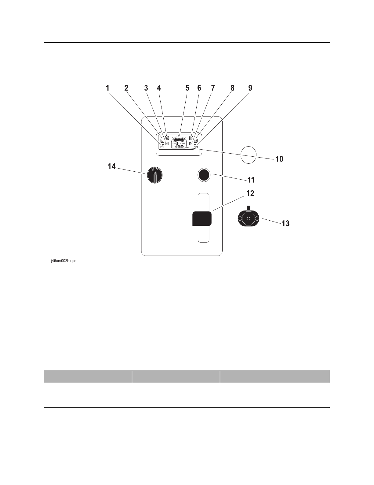
Power Unit
Controls and Indicators
1. Not used
2. Not used
3. Battery indicator
4. Low fuel indicator
5. Fuel gauge
6. Engine oil pressure indicator
7. Coolant temperature indicator
Item Description Notes
1. Not used
2. Not used
8. Hydraulic fluid temperature indicator
9. Glow plug indicator
10. Hourmeter
11. Cold start button
12. Throttle
13. Auxiliary outlet
14. Ignition switch
CMW
®

MR90 Operator’s Manual Controls - 23
c00ic008w.eps
Power Unit
Item Description Notes
3. Battery indicator Indicates low battery voltage.
4. Low fuel indicator Displays fuel level near
empty.
5. Fuel gauge Displays fuel level in tank. Fuel tank holds 15 gal (56.85 L).
NOTICE: Notice: Use ultra low sulfur
fuel only.
6. Engine oil pressure
indicator
Lights when engine oil
pressure falls below 8-12 psi
(.6-.8 bar).
Also lights briefly when
engine is started.
If light remains on:
• Turn off engine.
• Check oil level.
• If pressure is still low, consult
engine manual.
CMW
®

Controls - 24 MR90 Operator’s Manual
c00ic232h.eps
Power Unit
Item Description Notes
7. Coolant temperature
indicator
Lights when engine coolant
temperature is over 275°F
(135°C).
Also, lights briefly when
engine is started.
8. Hydraulic fluid
temperature indicator
Lights and alarm sounds
when hydraulic fluid is
overheating.
9. Glow plug indicator Lights when cold start button
is pressed.
If light remains on:
• Turn off engine and let unit cool.
• Check fan belt tension.
• Check for low coolant level.
• Check cooling fins for dirt and
debris.
Check hydraulic fluid level.
Reduce load.
Ensure oil cooler is clean.
10. Hourmeter Displays engine operating
time.
®
CMW
Hourmeter runs when ignition switch
is on.
Use these times to schedule service.
MR90 Operator’s Manual Controls - 25
c00ic179h.eps
Power Unit
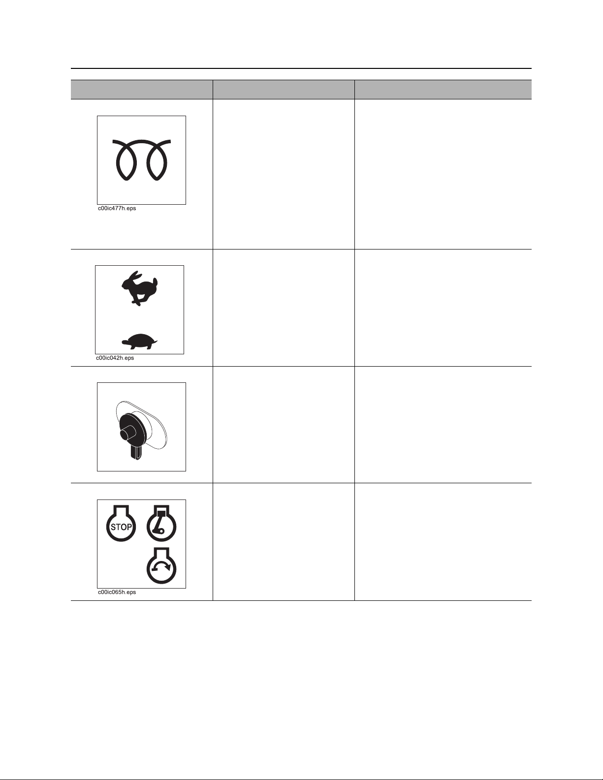
Item Description Notes
11. Cold start button To help start cold engine, turn
ignition switch to first position.
Press cold start button as
directed in notes.
Release button, then turn
ignition switch clockwise to
start.
12. Throttle To increase engine speed,
move up.
To decrease engine speed,
move down.
13. Auxiliary outlet To operate work lights or
other 12V devices, plug into
outlet.
IMPORTANT: Press cold start button
according to temperatures below.
• If ambient temperature is below
40°F (4°C), press and hold button
for five seconds.
• If ambient temperature is below
20°F (-7°C), press and hold
button for ten seconds.
• Do not press for more than 20
seconds continuously.
Outlet has power only when ignition
switch is on.
14. Ig n iti o n sw itch T o star t engine, insert key and
turn clockwise.
To stop engine, turn key
counterclockwise.
CMW
®
Controls - 26 MR90 Operator’s Manual
Power Unit
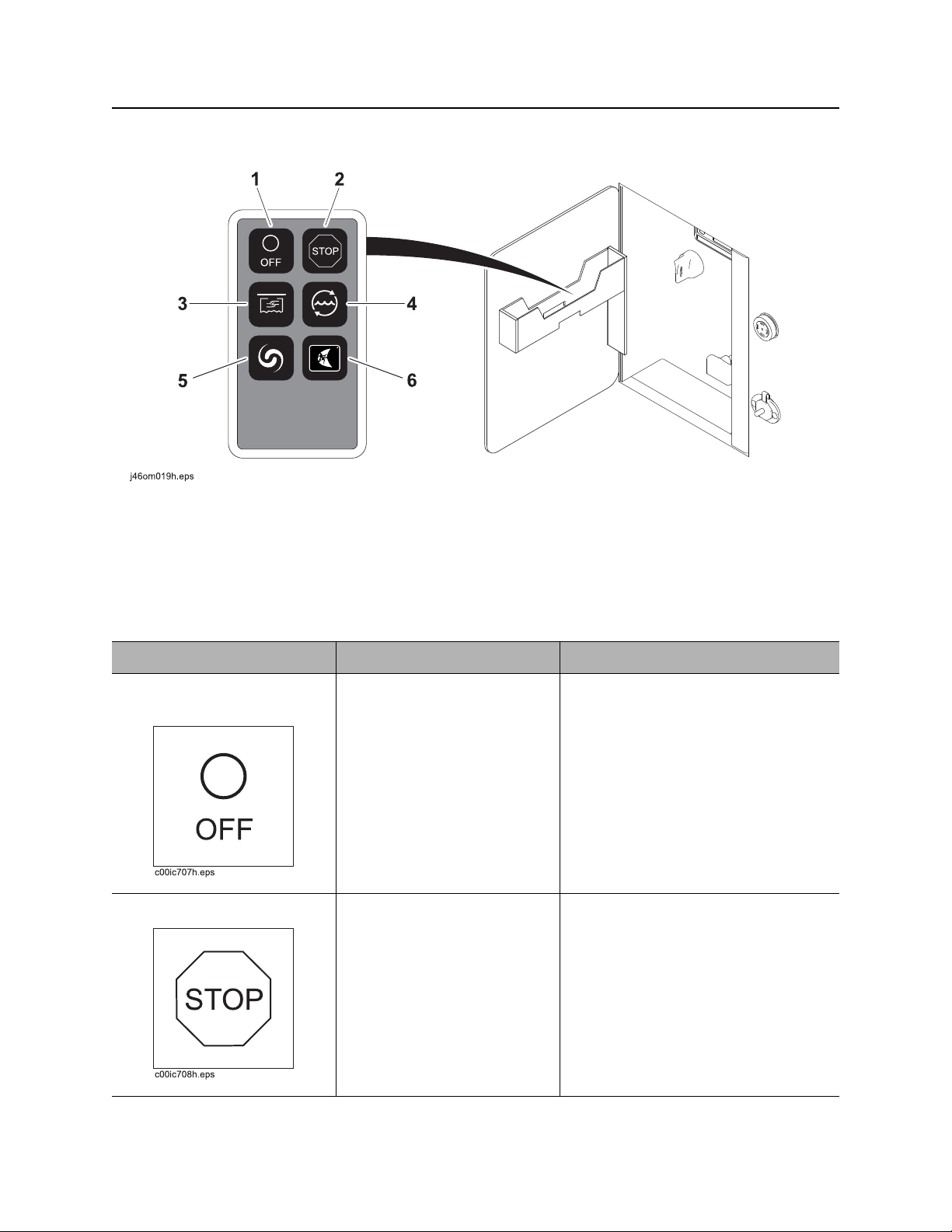
Remote Control (optional)
1. Remote control power button
2. Remote stop button
3. Pit pump button
Item Description Notes
1. Remote control power
button
2. Remote stop button To stop the engine, press.
T o turn r emote control module
off, press.
4. Cleaning pump button
5. Mix/supply pump button
6. Not used
IMPORTANT:
• Pressing any button will turn the
remote on.
• Turning the remote off does not
shut off pumps.
CMW
®
MR90 Operator’s Manual Controls - 27
Power Unit
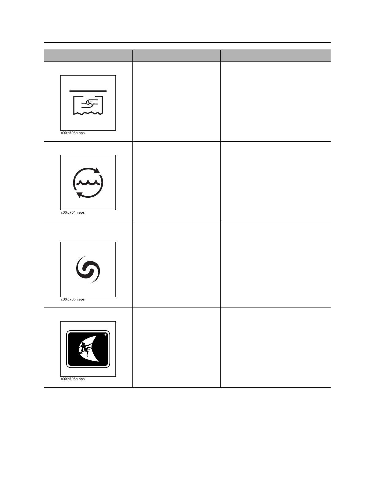
Item Description Notes
3. Pit pump button To turn pit pump on and off,
press.
4. Cleaning pump button To turn cleaning pump on and
off, press.
5. Mix/supply pump
button
To turn mix/supply pump on
and off, press.
Pit pump control must be engaged for
the remote function to work. See “Pit
pump/pressure wash pump selector”
on page 35.
Switch at control panel must be on for
remote function to work. See
“Cleaning pump switch” on page 34.
Switch at control panel must be on for
remote function to work. See “Mix/
supply pump switch” on page 34.
6. Not used
CMW
®

Controls - 28 MR90 Operator’s Manual
Power Unit
Indicators
1. Fluid low warning light 2. Fluid full warning light
Item Description Notes
1. Fluid low warning light Amber light will flash when
volume of fluid in MR90 tank
is too low.
2. Fluid full warning light Green light will flash when
volume of fluid in dirty side of
MR90 tank is full.
IMPORTANT: This light is magnetic
and can be moved to ensure better
visibility.
IMPORTANT: This light is magnetic
and can be moved to ensure better
visibility.
CMW
®
MR90 Operator’s Manual Controls - 29
c00ic654w.eps
Power Unit
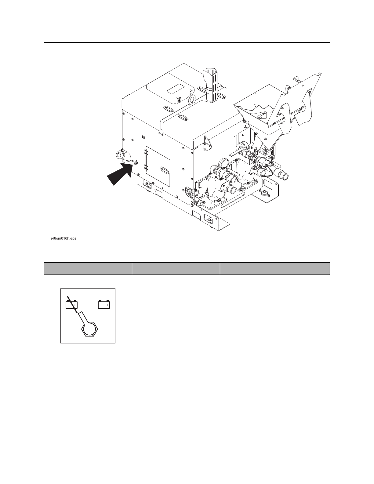
Miscellaneous
Item Description Notes
Battery disconnect switch To connect, move clockwise.
To disconnect, move
counterclockwise.
CMW
®

Controls - 30 MR90 Operator’s Manual
Mixing Unit
Mixing Unit
Gauges
Hydrocyclone pressure gauge
Item Description Notes
Hydrocyclone pressure
gauge
Indicates the pressure of fluid
moving through the
hydrocyclones.
Gauge should read 30-35 psi
(2.06-2.41 bar).
IMPORTANT:
• If gauge reads lower than 30-35
• If gauge reads higher than 30-35
psi (2.06-2.41 bar), check
hydrocyclones. See “Clean
Hydrocyclones” on page 94.
psi (2.06-2.41 bar) check the Ystrainer. See“Clean Y -S trainer” on
page 79.
CMW
®

MR90 Operator’s Manual Controls - 31
Mixing Unit
Valves
1. Fluid sample valve
2. Circulating jet valve
3. Mix hopper valve
Item Description Notes
1. Fluid sample valve To obtain a sample of drilling
fluid for testing, open valve.
2. Circulating jet valve T o circulate fluid while mixing,
open valve.
To stop circulation, close
valve.
3. Mixing hopper valve To add drilling additives to
hopper, open valve.
To stop flow of drilling
additives, close valve.
4. Venturi jet valve
5. Hydrocyclone valve
6. Drill supply valve
CMW
®

Controls - 32 MR90 Operator’s Manual
Mixing Unit
Item Description Notes
4. Venturi jet valve To allow flow from hopper to
mixing venturi, open valve.
To stop flow from hopper to
mixing venturi, close valve.
5. Hydrocyclone valve To allow air flow to operate
hydrocyclones, open valve.
To stop air flow from
hydrocyclones, close valve.
6. Drill supply valve To supply fluid to drill, open
valve.
To stop supply of fluid to drill,
close valve.
IMPORTANT:
• Open valve only when pouring
additives into hopper for mixing.
Close valve when finished.
• Do not open valve unless pump is
running and venturi jet valve is
open. Fluid could flow back into
hopper.
CMW
®

MR90 Operator’s Manual Controls - 33
Recycling Unit
Recycling Unit
Controls
1. Cleaning pump switch
2. Mix/supply pump switch
3. Pit pump auto control switch
4. Shaker control
5. Pit pump/pressure wash pump selector
6. Screen forward/rear tilt control
7. Screen left/right tilt control
8. Spoils hopper mixer control*
9. Spoils hopper door control*
10. Shaker speed control
11. Pit pump speed adjustment control
*optional
CMW
®

Controls - 34 MR90 Operator’s Manual
Recycling Unit
Item Description Notes
1. Cleaning pump switch To turn cleaning pump on,
press top.
To turn pump off, press
bottom.
2. Mix/supply pump
switch
3. Pit pump auto control
switch
4. Shaker control T o start shaker , push leve r up.
To turn mix/supply pump on,
press top.
To turn pump off, press
bottom.
To turn pit pump auto control
on, press top.
To allow manual control,
press bottom.
IMPORTANT: Leave pit pump auto
control on to reduce possibility of
over-filling dirty side of MR90 tank.
CMW
To stop shaker, pull lever
back.
®

MR90 Operator’s Manual Controls - 35
Recycling Unit
Item Description Notes
5. Pit pump/pressure
wash pump selector
6. Screen front/rear tilt
control
7. Screen left/right tilt
control
To turn pit pump on, push
lever up.
To turn pressure washer
pump on, pull lever back.
To turn pumps off, center
lever.
To raise front of screens,
push lever up.
To lower front of screens, pull
lever back.
To tilt screens to the right,
push lever up.
IMPORTANT:
• Pit pump lever must be engaged
for remote to function.
• Do not leave lever pulled back
when not using wash wand.
Damage may occur.
8. Spoils hopper mixer
control (optional)
To tilt screens to the left, pull
lever back.
To turn spoils hopper mixer
counterclockwise, push lever
up.
To turn spoils mixer
clockwise, pull lever back.
To turn spoils hopper mixer
off, center lever.
CMW
®

Controls - 36 MR90 Operator’s Manual
Recycling Unit
Item Description Notes
9. Spoils hopper door
control (optional)
10. Shaker speed control To increase shaker speed,
11. Pit pump speed
adjustment control
To raise door on back of
spoils hopper, push lever up.
To lower door on back of
spoils hopper, pull lever back.
turn counterclockwise.
To decrease shaker speed,
turn clockwise.
To increase pit pump flow,
turn clockwise.
To decrease pit pump flow,
turn counterclockwise.
CMW
®

MR90 Operator’s Manual Controls - 37
Recycling Unit
Auxiliary Controls
1. Fresh water transfer pump switch
2. Auxiliary outlet switch
Item Description Notes
1. Fresh water transfer
pump switch
To turn fresh water transfer
pump on, press top.
To turn pump off, press
bottom.
3. Auxiliary outlet
Transfers water from 300 gal tank to
the MR90 tank.
CMW
®

Controls - 38 MR90 Operator’s Manual
c00ic179h.eps
Recycling Unit
Item Description Notes
2. Auxiliary outlet switch To turn auxiliary outlet on,
press top.
To turn auxiliary outlet off,
press bottom.
3. Auxiliary outlet To operate work lights or
other 12V devices, plug into
outlet.
Outlet has power only when ignition
switch is on.
CMW
®

MR90 Operator’s Manual Controls - 39
Recycling Unit
Valves
1. Spoils hopper drain valve*
2. Antifreeze valve
3. Water drain valve
4. Dirty side tank drain valve
Item Description Notes
1. Spoils hopper drain
valve (optional)
2. Antifreeze valve To mix antifreeze into the
3. Water drain valve To drain water from fresh
4. Dirty side tank drain
valve
5. Clean side tank drain
valve
To drain spoils hopper, open
valve.
fresh water pump, open
valve.
water tank, open valve.
To drain dirty side tank, open
valve.
T o drain clea n side tank, open
valve.
5. Clean side tank drain valve
6. Fresh water control valve
7. Mud flow control valve
*Optional
CMW
®

Controls - 40 MR90 Operator’s Manual
Recycling Unit
Item Description Notes
6. Fresh water control
valve
7. Mud flow control valve To increase mud flow onto
T o transfer water from 300 gal
tank to MR90 tank, open
valve.
screens, move valve toward
open.
To decrease mud flow onto
screens, move valve toward
close.
IMPORTANT:
• Turn on with fresh water transfer
pump to transfer water to MR90
tank.
• Shut off when MR90 tank is full to
avoid overflow from dirty side tank
into fresh water tank.
CMW
®

MR90 Operator’s Manual Controls - 41
Recycling Unit
Trailer Controls
1. Hydraulic trailer jack control 2. Manual trailer jack handle
Item Description Notes
1. Hydraulic trailer jack
control
2. Manual trailer jack
handle
Push lever down to lower
front of trailer.
Pull lever up to raise front of
trailer.
Turn handle clockwise to
lower front of trailer.
Turn handle counterclockwise
to raise front of trailer.
IMPORTANT: Ensure manual trailer
jack control is disengaged.
IMPORTANT:
• Only use if hydraulic trailer jack
control will not work.
• Handle is stowed in toolbox.
CMW
®

Controls - 42 MR90 Operator’s Manual
Recycling Unit
CMW
®

MR90 Operator’s Manual Prepare - 43
Prep are
Chapter Contents
Gather Information . . . . . . . . . . . . . . . . . . . . . . . . . 44
• Arrange for Traffic Control . . . . . . . . . . . . . . . . . . . . . . . . . . . . . . . . . . .44
• Prepare for Working Near Existing Utilities . . . . . . . . . . . . . . . . . . . . . .44
• Plan for Emergency Services . . . . . . . . . . . . . . . . . . . . . . . . . . . . . . . . .44
Inspect Jobsite . . . . . . . . . . . . . . . . . . . . . . . . . . . . 45
Prepare Jobsite . . . . . . . . . . . . . . . . . . . . . . . . . . . 45
Check Supplies and Prepare Equipment . . . . . . . 46
• Assemble Accessories . . . . . . . . . . . . . . . . . . . . . . . . . . . . . . . . . . . . . .46
• Check Supplies . . . . . . . . . . . . . . . . . . . . . . . . . . . . . . . . . . . . . . . . . . .46
• Prepare Equipment . . . . . . . . . . . . . . . . . . . . . . . . . . . . . . . . . . . . . . . .46
CMW
®

Prepare - 44 MR90 Operator’s Manual
Gather Information
Gather Information
A successful job begins before the excavation. The first step in planning is reviewing information already
available about the job and jobsite.
Arrange for Traffic Control
If working near a road or other traffic area, contact local authorities about safety procedures and
regulations.
Prepare for Working Near Existing Utilities
If jobsite may contain electrical lines, wear protective boots and gloves meeting the following standards:
• Boots must have high tops and meet th e electric hazard protection requirements of ASTM F2413 or
ASTM 1117, when tested at 14,000 volts. Tuck legs of pants completely inside boots.
• Gloves must have 17,000 AC maximum use voltage, according to ASTM spec ifica tio n D12 0.
If working around higher voltage, use gloves and boots with appropriately higher ratings.
Plan for Emergency Services
Have the telephone numbers for local emergency and medical facilities on hand. Check that you will have
access to a telephone.
CMW
®

MR90 Operator’s Manual Prepare - 45
Inspect Jobsite
Inspect Jobsite
• Follow U.S. Department of Labor regulations on excavating and trenching (Part 1926, Subpar t P) and
other similar regulations.
• Contact your local One-Call (811 in USA) or the One-Call referral number (888-258-0808 in USA and
Canada) to have underground utilities located before digging. Also contact any utilities that do not
participate in the One-Call service.
• Inspect jobsite and perimeter for evidence of underground hazards, such as:
– “Buried utility” notices
– Utility facilities without overhead lines
– Gas or water meters
– Junction boxes
– Drop boxes
– Light poles
– Manhole covers
– Sunken ground
• Mark location of all buried utilities and obstructions.
Prepare Jobsite
Jobsite hazards could cause death or serious injury. Use
correct equipment and work methods. Use and maintain proper safety
equipment.
NOTICE:
• If jobsite classification is in question or if the possibility of unmarked electric utilities exists, classify
jobsite as electric.
• Cutting high voltage cable can cause electrocution. Expose lines by hand before digging.
• All vegetation near operator’s station must be removed. Conta ct with trees, shrubs, or weeds during
electrical strike could result in electrocution.
CMW
®

Prepare - 46 MR90 Operator’s Manual
Check Supplies and Prepare Equipment
Check Supplies and Prepare Equipment
Assemble Accessories
Fire Extinguisher
If required, mount a fire extinguisher near the power unit but away from possible points of ignition. The fire
extinguisher should always be classified for both oil and electric fires. It should meet legal and regulatory
requirements.
Check Supplies
• water and additional hoses
•fuel
• drilling fluid additives, such as bentonite and polymer
• drilling fluid measurement kit
Prepare Equipment
Fluid Levels
•fuel
• engine oil
Condition and Function
• filters (air, oil)
•tires
• hoses and valves
• couplers and fittings
• water tank
• screens
CMW
®

MR90 Operator’s Manual Transport - 47
Transport
Chapter Contents
Lift . . . . . . . . . . . . . . . . . . . . . . . . . . . . . . . . . . . . . . 48
• Points . . . . . . . . . . . . . . . . . . . . . . . . . . . . . . . . . . . . . . . . . . . . . . . . . . .48
• Procedure . . . . . . . . . . . . . . . . . . . . . . . . . . . . . . . . . . . . . . . . . . . . . . . .48
Haul . . . . . . . . . . . . . . . . . . . . . . . . . . . . . . . . . . . . . 50
CMW
®

Transport - 48 MR90 Operator’s Manual
Lift
Lift
Crushing weight. If load falls or moves it could kill or crush
you. Use proper procedures and equipment or stay away.
Points
Lifting points are identified by lifting decals. Lifting at other points is unsafe
and can damage machinery.
Procedure
Tank
Use crane capable of supporting the equipment's
size and weight. See “Specifications” on page 103
or measure and weigh equipment before lifting. Lif t
mixing tank by attaching lif ting de vices at lift points
and joining at a common lift points.
IMPORTANT: Empty tank before lifting.
Power Unit
Use crane capable of supporting the equipment's
size and weight. See “Specifications” on page 103
or measure and weigh equipment before lifting. Lif t
power unit by attaching lifting device at lift point.
CMW
®

MR90 Operator’s Manual Transport - 49
Lift
Recycling Unit
Use crane capable of supporting the equipment's
size and weight. See “Specifications” on page 103
or measure and weigh equipment before lifting. Lif t
recycling unit by attaching lifting device at lift point.
IMPORTANT: Empty before lifting.
CMW
®

Transport - 50 MR90 Operator’s Manual
TrailerHitchAdjust_T9.epsTrailerHitchAdjust_T9.eps
Lift
Haul
Inspect Trailer
• Check hitch for wear and cracks. Lubricate if needed.
• Check battery for 12V charge.
• Inspect lights for cleanliness and correct operation. Inspect reflectors and replace if needed.
• Check tire pressure. Check lug nut torque with a torque wrench.
• Ensure trailer brakes are adjusted to come on in synchronization with tow vehicle brakes.
• Check ramps (if equipped) and trailer bed for cracks.
Hitch Trailer
1. Back tow vehicle to trailer.
2. Put manual transmission into first or reverse gear or automatic transmission into park. Turn off ignition.
Set parking brake.
3. Connect trailer drawbar, lunette or coupler to
tow vehicle hitch and lock in place with lock
pin. If needed, adjust drawbar, lunette or
coupler height (shown) to level load.
4. Connect safety chains to tow vehicle chain
keepers (cross-shaped slots on bumper of
tow vehicle). Attach left chain to right side of
tow vehicle and vice versa to cradle hitch. Do
not connect to pintle hook or hitch ball.
5. Connect breakaway switch cable to tow
vehicle. Do not connect to pintle hook or hitch
ball.
6. Plug trailer electrical connector into tow
vehicle connector.
7. Use jack crank to raise jack base and stow.
8. Remove wheel blocks.
Unhitch Trailer
1. Stop tow vehicle and trailer on level ground.
2. Put manual transmission into first or reverse gear or automatic transmission into park. Turn off ignition.
Set parking brake.
3. Block trailer wheels.
4. To unhitch trailer from tow vehicle, reverse “Hitch Trailer” steps
CMW
®

MR90 Operator’s Manual Handle Fluid - 51
Handle Fluid
Chapter Contents
Mix Fluid . . . . . . . . . . . . . . . . . . . . . . . . . . . . . . . . . 52
• Set Up. . . . . . . . . . . . . . . . . . . . . . . . . . . . . . . . . . . . . . . . . . . . . . . . . . .52
• Mixing Fluid. . . . . . . . . . . . . . . . . . . . . . . . . . . . . . . . . . . . . . . . . . . . . . .52
• Transferring Fluid . . . . . . . . . . . . . . . . . . . . . . . . . . . . . . . . . . . . . . . . . .53
Recycle Fluid. . . . . . . . . . . . . . . . . . . . . . . . . . . . . . 54
• Set Up. . . . . . . . . . . . . . . . . . . . . . . . . . . . . . . . . . . . . . . . . . . . . . . . . . .54
• Recycling Fluid . . . . . . . . . . . . . . . . . . . . . . . . . . . . . . . . . . . . . . . . . . . .56
• Transferring Fluid . . . . . . . . . . . . . . . . . . . . . . . . . . . . . . . . . . . . . . . . . .56
Operate in Cold Weather . . . . . . . . . . . . . . . . . . . . 57
CMW
®

Handle Fluid - 52 MR90 Operator’s Manual
Mix Fluid
Mix Fluid
Set Up
1. Position fluid unit and connect to drilling unit. See drilling unit operator’s manual.
IMPORTANT: Leave unit hitched to towing vehicle or properly stabilized.
2. Block trailer wheels.
Mixing Fluid
Jobsite hazards could cause death or serious injury. Use
correct equipment and work methods. Use and maintain proper safety
equipment.
To help avoid injury:
• Wear personal protective equipment including hard hat, safety eye wear, and hearing protection.
• Do not wear jewelry or loose clothing.
Improper handling or use of chemicals may result in illness, injury, or
equipment damage. Follow instructions on labels and in material safety data sheets
(MSDS).
1. Verify that hopper throat is not plugged before mixing.
2. Fill MR90 tank with water. Allow room for additives.
3. Open circulation valve and tank discharge valve.
4. Start engine and run at full throttle.
5. Turn mix/supply pump on.
6. Open mixing hopper valve.
IMPORTANT: Do not open valve unless pump is running and venturi jet valve is open. Fluid
could flow back into hopper.
7. Open hopper lid and pour in bentonite. See page 61.
IMPORTANT: Before adding bentonite to drilling fluid, be sure drilling unit is equipped to use a
bentonite mixture.
®
CMW

MR90 Operator’s Manual Handle Fluid - 53
Mix Fluid
8. Close hopper valve and close hopper lid.
9. Mix well.
10. Add liquid additives directly to MR90 tank.
IMPORTANT: Pumps must be circulating when adding liquid additives.
Transferring Fluid
Electric shock. Contacting electric lines will cause death or serious injury.
Know location of lines and stay away.
To help avoid injury: Keep in mind, if electrical strike occurs while fluid hose is connected to drilling
unit, fluid system will also become electrified.
1. Connect hose from mixing pump to drilling unit.
2. Open venturi jet valve and drill supply valve.
IMPORTANT: If drilling fluid contains bentonite, leave jet valve open to allow continuous mixing
while drilling.
3. Run engine at full throttle.
CMW
®

Handle Fluid - 54 MR90 Operator’s Manual
Recycle Fluid
Recycle Fluid
Set Up
1. Position fluid unit and connect to drilling unit. See drilling unit operator’s manual.
IMPORTANT: Leave unit hitched to towing vehicle or properly stabilized.
2. Block trailer wheels.
Connect Pit Pump
1. Connect hose at 1B and secure other end at
1A.
2. Connect hose at 2B and secure other end at
2A.
CMW
®

MR90 Operator’s Manual Handle Fluid - 55
Recycle Fluid
3. Ensure pit pump is not directly on bottom of
pit by suspending it in the pit or digging a
shelf for it to sit on (shown).
CMW
®

Handle Fluid - 56 MR90 Operator’s Manual
Recycle Fluid
Recycling Fluid
1. Level screens left to right. See “Screen left/right tilt control” on page 35.
2. Turn shaker on.
3. Turn on cleaning pump and check that hydrocyclones are operating at 30 psi (2.06 bar).
IMPORTANT: MR90 tank should be at least half full before turning on cleaning pump.
4. Turn on pit pump to supply used mud to shaker screens.
IMPORTANT: Use auto mode for pit pump to avoid overflowing MR90 tank. See “Pit pump auto
control switch” on page 34.
5. Routinely check mud weight and sand content to prevent damage to drill. See page 66.
6. Level screens front to rear. See “Screen front/rear tilt control” on page 35.
IMPORTANT:
• If front of shaker is too high, large amounts of water will exit the shaker with the spoils.
• Monitor and adjust front/rear screen tilt as soil conditions change.
Transferring Fluid
Electric shock. Contacting electric lines will cause death or serious injury.
Know location of lines and stay away.
To help avoid injury: Keep in mind, if electrical strike occurs while fluid hose is connected to drilling
unit, fluid system will also become electrified.
1. Connect hose from mixing pump to drilling unit.
2. Open venturi jet valve and drill supply valve.
IMPORTANT: If drilling fluid contains bentonite, leave jet valve open to allow continuous mixing
while drilling.
3. Run engine at full throttle.
CMW
®

MR90 Operator’s Manual Handle Fluid - 57
Operating in Cold Weather
Operating in Cold Weather
For successful operation in cold weather, follow these procedures.
• Use mix/supply pump to keep drilling fluid circulating at all times, even during transport to and from the
jobsite.
• Use antifreeze wash pump to mix antifreeze into system.
• If possible, use all drilling fluid in MR90 tank before transporting unit.
CMW
®

Handle Fluid - 58 MR90 Operator’s Manual
Operating in Cold Weather
CMW
®

MR90 Operator’s Manual Systems and Equipment - 59
Systems and Equipment
Chapter Contents
Recommended Products . . . . . . . . . . . . . . . . . . . . 60
• Guidelines . . . . . . . . . . . . . . . . . . . . . . . . . . . . . . . . . . . . . . . . . . . . . . .60
• Polymer . . . . . . . . . . . . . . . . . . . . . . . . . . . . . . . . . . . . . . . . . . . . . . . . .61
• Bentonite . . . . . . . . . . . . . . . . . . . . . . . . . . . . . . . . . . . . . . . . . . . . . . . .61
• Mixtures . . . . . . . . . . . . . . . . . . . . . . . . . . . . . . . . . . . . . . . . . . . . . . . . .62
Drilling Fluid Requirements. . . . . . . . . . . . . . . . . . 64
Drilling Fluid Measurements . . . . . . . . . . . . . . . . . 65
• Funnel Viscosity . . . . . . . . . . . . . . . . . . . . . . . . . . . . . . . . . . . . . . . . . . .65
• Mud Weight. . . . . . . . . . . . . . . . . . . . . . . . . . . . . . . . . . . . . . . . . . . . . . .66
• Sand Content . . . . . . . . . . . . . . . . . . . . . . . . . . . . . . . . . . . . . . . . . . . . .66
Screens . . . . . . . . . . . . . . . . . . . . . . . . . . . . . . . . . . 67
CMW
®

Systems and Equipment - 60 MR90 Operator’s Manual
Recommended Products
Recommended Products
Improper handling or use of chemicals may result in illness, injury, or
equipment damage. Follow instructions on labels and in material safety data sheets
(MSDS).
Use breathing protection when exposed to silica dust.
270-4952
For productive drilling and equipment protection, use these recommended Baroid® products, available
®
from your Ditch Witch
• Soda ash
• Quik-Gel
®
dry powder bentonite (p/n 259-804)
dealer.
• Liqui-Trol™ liquid polymer suspension (p/n 259-808)
•Quik-Trol
• Bore-Gel
• E-Z Mud™ Gold dry powder polymer (p/n 255-1012)
®
dry powder polymer (p/n 259-809)
®
drilling fluid (p/n 259-807)
Guidelines
Match drilling fluid to soil type. This chart is meant as a guideline only . See your local Ditch Witch dealer for
soil conditions and drilling fluid recommendations for your area. Also see our interactive Drilling Fluid
Formulator at www.ditchwitch.com.
Soil type Drilling fluid recommendation
smooth, flowing sand bentonite or Bore-Gel + medium chain polymer
coarse sand or light soil bentonite or Bore-Gel
heavy clay medium chain polymer
swelling clay medium chain polymer
rock Bore-Gel
CMW
®

MR90 Operator’s Manual Systems and Equipment - 61
Recommended Products
Polymer
This drilling fluid additive provides excellent lubrication and increases viscosity in average soils and heavy
clay. In swelling clay, polymer can reduce swelling that traps pipe in the bore.
There are two types of polymer:
• long chain such as Baroid
NOTICE: Long chain polymer is not recommended for this unit.
• medium chain such as Baroid Quik-Trol
®
EZ-Mud Gold
Bentonite
Bentonite is a dry powder. When properly mixed with water, it forms a thin cake on bore walls, lubricating
the bore, keeping it open, and holding fluid in the bore.
Some things to remember when mixing bentonite:
• Use clean water free of salt, calcium, or excessive chlorine.
• Use water with pH level between 9 and 10.
• Use water with hardness of less than 120 ppm.
• Do not use bentonite containing sand.
• Mix bentonite thoroughly or it will settle in tank.
• Do not mix bentonite to a funnel viscosity of over 50.
For information on measuring funnel viscosity, see “Drilling Fluid Measurements” on page 65.
CMW
®

Systems and Equipment - 62 MR90 Operator’s Manual
Recommended Products
Mixtures
NOTICE: Bentonite does not mix well in water containing polymer. To use both, mix bentonite first, then
add polymer.
• If chemicals are added in the wrong order, they will not mix properly and will form clumps.
• If tank contains bentonite/polymer mix and more drilling fluid is needed, completely empty tank and
start with fresh water before mixing another batch.
General mixing order
1. Soda ash
2. Bentonite
3. Polymer
Bore-Gel
drilling fluid viscosity for expected drilling conditions.
®
contains premixed bentonite, polymer, and soda ash. Follow guidelines below to ensure proper
Conditions Amount to Use
normal drilling 15 lb/100 gal 7 kg/380 L
sand or gravel up to 45 lb/100 gal up to 21 kg/380 L
rock up to 50 lb/100 gal up to 23 kg/380
Basic Fluid Recipes
Soil type Mixture/100 gal (378 L) of water Notes
fine sand 35 lb (16 kg) Bore-Gel
coarse sand 35 lb (16 kg) Bore-Gel
.5 lb (225 g) No-Sag
fine sand below water
table
coarse sand below
water table
40 lb (18 kg) Bore-Gel
.75 lb (340 g) Quik-Trol
40 lb (18 kg) Bore-Gel
.75 lb (340 g) Quik-Trol
.75 lb (340 g) No-Sag
Add .5 lb (225 g) of Quik-Trol for
additional filtrate control
Add .5 - 1 gal (2-4 L) of Dinomul in high
torque situations
Add .5 - 1 gal (2-4 L) of Dinomul in high
torque situations
gravel 50 lb (23 kg) Bore-Gel
.75 lb (340 g) Quik-Trol
.75 lb (340 g) No-Sag
cobble 50 lb (23 kg) Bore-Gel
.75 lb (340 g) Quik-Trol
.75 lb (340 g) No-Sag
®
CMW
Add .5 lb (225 g) of Barolift to reduce loss
of returns
Add .5 lb (225 g) of Barolift to reduce loss
of returns

MR90 Operator’s Manual Systems and Equipment - 63
Recommended Products
Soil type Mixture/100 gal (378 L) of water Notes
sand, gravel, clay or
shale
clay .5 lb (225 g) Poly Bore Flow rate should be 3-5 parts fluid to 1
swelling/sticky clay .75 - 1 lb (340-450 g) EZ-Mud
solid rock (shale) 40 lb (18 kg) Bore-Gel Use .5 pt (235 mL) of No Sag for large
solid rock (other than
shale)
rock/clay mixture 40 - 50 lb (18-23 kg) Bore-Gel
rock/sand mixture 40 - 50 lb (18-23 kg) Bore-Gel Use .5 pt (235 mL) of No Sag for large
fractured rock 50 lb (23 kg) Bore-Gel
35 - 40 lb (16-18 kg) Bore-Gel
.5lb (227 g) EZ-Mud Gold
Gold
40 - 50 lb (18-23 kg) Bore-Gel Use .5 pt (235 mL) of EZ-Mud in reactive
.5 lb (227 g) EZ-Mud Gold
.5 - 1lb (225-450 g) No-Sag
Vary mixture according to percentage of
sand and clay
part soil.
Flow rate should be 3-5 parts fluid to 1
part soil.
diameter or longer bores
shales
diameter or longer bores
Use .5 lb (225 g) of Barolift to reduce fluid
loss to formation
CMW
®

Systems and Equipment - 64 MR90 Operator’s Manual
Drilling Fluid Requirements
Drilling Fluid Requirements
1. Determine drilling conditions and choose appropriate drilling fluid mix.
2. Estimate amount of supplies needed and check availability.
• Drilling fluid
• Water supply. If more water than can be carried with the unit will be needed, arrange to transport
additional water.
• Bentonite and/or polymer
3. Check water quality.
• Use meter or pH test strips to test pH of water. If pH is below 9.0, add 1 lb (454 g) soda ash per
tank. Test and repeat until pH is between 9 and 10.
• Check water hardness using hardness test strips. Treat with soda ash if hardness exceeds 125
ppm.
CMW
®

MR90 Operator’s Manual Systems and Equipment - 65
Drilling Fluid Measurements
Drilling Fluid Measurements
Fluid measurements are important in ensuring the drilling system functions correctly. The viscosity, mud
weight, and sand content of drilling fluids must be controlled and can be measured using the drilling fluid
test kit (p/n 191-158), available from your Ditch Witch
Funnel Viscosity
Viscosity is the measure of internal resistance of a fluid to flow; the greater the resistance, the higher the
viscosity.
To determine viscosity, you will need the Marsh funnel and measuring cup in your drilling fluid test kit.
IMPORTANT: Make sure Marsh funnel is clean and free of obstruction and that you have a stopwatch
available for timing the viscosity.
1. Using wash hose and a clean container, take a fresh
sample of drilling fluid. The sample must be at least
1.5 qt (1.4 L).
®
dealer.
2. With finger over bottom of funnel, fill with fluid from
the container through the screen until fluid reaches
the bottom of the screen.
3. Move funnel over 1 qt (.95 L) container.
4. Remove finger from bottom of funnel and use the
stopwatch to count the number of seconds it t akes for
1 qt (.95 L) of fluid to pass through the funnel. The
number of seconds is the viscosity.
5. Thoroughly rinse measuring cup and Marsh funnel.
CMW
®

Systems and Equipment - 66 MR90 Operator’s Manual
Drilling Fluid Measurements
Mud Weight
The density of a given liquid is the mud weight.
To determine mud weight, you will need the mud balance and scale in your drilling fluid test kit (p/n 191-
158), available from your Ditch Witch
IMPORTANT: Make sure all pieces of mud weight kit are clean and free of obstruction before measuring
drilling fluid.
1. Place mud balance base on level surface.
2. Fill the cup to the top with mud sample to be weighed. See “Fluid sample valve” on page 31.
3. Secure the lid on the cup.
IMPORTANT: Mud should be expelled through the hole in the lid to ensure cup is full and any trapped a ir
is freed from the cup.
4. Cover the hole in the cap with a finger and wash all mud from outside of the cup.
®
dealer.
5. Place balance on the scale and slide rider along the arm until the level bubble indicates the scale is
level. The mud weight of the drilling fluid is the number indicated by the scale.
6. Thoroughly rinse mud weight cup and scale.
Sand Content
Sand content is measured by determining the volume percent of sand-sized particles present in the drilling
fluid.
To determine sand content, you will need the sand content tube, wash bottle, screen, and funnel in your
drilling fluid test kit.
IMPORTANT: Make sure sand content kit components are clean and free of obstruction before
measuring drilling fluid.
1. Fill sand content tube to the indicated mark with mud sample. See “Fluid sample valve” on page 31.
2. Use wash bottle to add water to the next mark.
3. Close tube and shake vigorously.
4. Pour mixture onto clean screen. Discard liquid passing through the screen.
5. Repeat steps 2-4 until all drilling fluid has been washed out of the tube.
6. Place funnel upside down over top of screen.
7. Slowly invert the assembly and insert the tip of the funnel into the mouth of the measuring tube.
8. Wash sand into measuring tube with wash bottle and allow sand to settle. The volume percen t of sand
is measured using the scale on the side of the measuring tube.
9. Thoroughly rinse all components of the sand content kit.
®
CMW

MR90 Operator’s Manual Systems and Equipment - 67
Screens
Screens
Use the chart below to determine which set of screens will work best for the soil type at the jobsite.
A. Clay B. Silt C. Sand D. Loam
Description P/N Micron
fine screen set 301-7191 165
301-7192 70
medium screen set 301-7189 225
301-7190 88
overlap area, both fine and medium screens can be used
coarse or very fine screens, contact Ditch Witch® dealer
CMW
®

Systems and Equipment - 68 MR90 Operator’s Manual
Screens
CMW
®

MR90 Operator’s Manual Complete the Job - 69
Complete the Job
Chapter Contents
Dispose of Fluid . . . . . . . . . . . . . . . . . . . . . . . . . . . 70
Rinse Equipment . . . . . . . . . . . . . . . . . . . . . . . . . . 70
Disconnect . . . . . . . . . . . . . . . . . . . . . . . . . . . . . . . 72
Stow Tools. . . . . . . . . . . . . . . . . . . . . . . . . . . . . . . . 72
Storage. . . . . . . . . . . . . . . . . . . . . . . . . . . . . . . . . . . 72
CMW
®

Complete the Job - 70 MR90 Operator’s Manual
Dispose of Fluid
Dispose of Fluid
Moving parts could cut off hand or foot. Stay away.
275-184
To help avoid injury: Never place hands through spoils door unless
engine is off and battery is disconnected.
Rotating shaft will cause death or serious injury. Stay
away.
270-1506
To help avoid injury: Leave cover on spoils hopper.
Dispose of unneeded fluid and waste products
using one of the methods described below.
1. Hook vacuum unit directly to MR90
connectors.
• Connect at 1 to drain clean side tank.
• Connect at 2 to drain dirty side tank.
• Connect at 3 to drain optional spoils
hopper.
2. Open optional spoils hopper door to dump
waste products. See “Spoils hopper door
control (optional)” on page 36.
IMPORTANT:
• Some areas may have regulations regarding
the disposal of waste products. Consult local
regulations.
• If a gelling agent is required, Baroid
428 is recommended.
®
IDP-
CMW
®

MR90 Operator’s Manual Complete the Job - 71
Rinse Equipment
Rinse Equipment
Pressurized fluid or air could pierce skin and cause
severe injury. Refer to operator’s manual for proper use.
Spray water onto equipment to remove dirt and
mud. Hose reel is equipped with a handle restraint
(shown).
• Pull latch forward and lift handle up to release.
• Pull latch forward and push handle down to
secure.
270-6035
CMW
®

Complete the Job - 72 MR90 Operator’s Manual
Disconnect
Disconnect
Disconnect and store hoses and cables.
Stow Tools
Make sure hoses, drilling fluid measurement kit,
and other tools are properly stowed.
Stow pit pump as shown.
Storage
Drain tank and ensure all fluid system valves are
open. Also open drain valve on pump.
CMW
®

MR90 Operator’s Manual Service - 73
Service
Chapter Contents
Service Precautions . . . . . . . . . . . . . . . . . . . . . . . . 74
• Welding Precaution . . . . . . . . . . . . . . . . . . . . . . . . . . . . . . . . . . . . . . . .74
• Washing Precaution . . . . . . . . . . . . . . . . . . . . . . . . . . . . . . . . . . . . . . . .74
Recommended Lubricants/Service Key . . . . . . . . 75
• Engine Oil Temp er a tur e Chart . . . . . . . . . . . . . . . . . . . . . . . . . . . . . . . .76
• Approved Coolant . . . . . . . . . . . . . . . . . . . . . . . . . . . . . . . . . . . . . . . . .76
• Approved Fuel. . . . . . . . . . . . . . . . . . . . . . . . . . . . . . . . . . . . . . . . . . . . .77
10 Hour . . . . . . . . . . . . . . . . . . . . . . . . . . . . . . . . . . 78
50 Hour . . . . . . . . . . . . . . . . . . . . . . . . . . . . . . . . . . 84
150 Hour . . . . . . . . . . . . . . . . . . . . . . . . . . . . . . . . . 87
300 Hour . . . . . . . . . . . . . . . . . . . . . . . . . . . . . . . . . 89
450 Hour . . . . . . . . . . . . . . . . . . . . . . . . . . . . . . . . . 90
900 Hour . . . . . . . . . . . . . . . . . . . . . . . . . . . . . . . . . 92
1800 Hour . . . . . . . . . . . . . . . . . . . . . . . . . . . . . . . . 92
As Needed . . . . . . . . . . . . . . . . . . . . . . . . . . . . . . . 93
200 Mile . . . . . . . . . . . . . . . . . . . . . . . . . . . . . . . . . . 98
3000 Mile . . . . . . . . . . . . . . . . . . . . . . . . . . . . . . . . . 99
12,000 Mile. . . . . . . . . . . . . . . . . . . . . . . . . . . . . . . 100
CMW
®

Service - 74 MR90 Operator’s Manual
Service Precautions
Service Precautions
Incorrect procedures could result in death, injury, or
property damage. Learn to use equipment correctly.
To help avoid injury:
• Unless otherwise instructed, all service should be performed with engine off.
• Refer to engine manufacturer’s manual for engine maintenance instructions.
Welding Precaution
NOTICE: Welding can damage electronics.
• Welding currents can damage electronic components. Connect welder ground close to welding
point and make sure no electronic comp on en ts are in the gro u nd path. .
• Disconnect battery at battery disconnect switch before welding to prevent damage to battery.
• Do not turn off battery disconnect switch with engine running, or alternator and other electronic
devices may be damaged.
Washing Precaution
NOTICE: W ater can damage electronics. When clean ing equipment, do not spray electrical component s
with water.
CMW
®

MR90 Operator’s Manual Service - 75
Recommended Lubricants/Service Key
Recommended Lubricants/Service Key
Item Description
DEO Diesel engine oil meeting or exceeding CH-4 per th e API service classification or E5 per
the European Automobile Manufacturer’s Association (ACEA) and SAE viscosity
recommended by engine manufacturer (SAE 10W30)
MPG Multipurpose grease meeting ASTM D217 and NLGI 1
THF
DEAC Diesel engine antifreeze/coolant meeting ASTM D5345 (prediluted) or D4985
NDO 30W non-detergent oil
MPL Multipurpose gear oil meeting API service classification GL-5 (SAE 80W90)
Proper lubrication and maintenance protects Ditch Witch® equipment from damage and failure. Service
intervals listed are for minimum requirements. In ex treme conditions, service machine more frequently.
Use only genuine Ditch Witch parts, filters, approved lubricants, TJC, and approved coolants to maintain
warranty. Fill to capacities listed in “Specifications” on page 121.
For more information on engine lubrication and maintenance, see your engine manual.
Tractor hydraulic fluid, similar to Phillips 66
Hydraulic Fluid, Texaco
(concentrate)
Check level of fluid or lubricant Check condition
Filter Change, replace, adjust, service or
®
TDH Oil, or equivalent
®
HG, Mobilfluid® 423, Chevron® Tractor
test
IMPORTANT: Use the “Service Record” on page 111 to record all required service to your machine.
CMW
®

Service - 76 MR90 Operator’s Manual
Temperature range anticipated before next oil change
Recommended Lubricants/Service Key
Engine Oil Temperature Chart
Approved Coolant
This unit was filled with John Deere® Cool-Gard® coolant before shipment from factory. Add only CoolGard (p/n 255-006) or any fully-formulated, ethylene glycol based, low-silicate, heavy-duty diesel engine
coolant meeting ASTM specification D5345 (prediluted) or D4985 (concentrate). Before using any other
kind of coolant, completely flush radiator.
NOTICE: Do not mix heavy-duty diesel engine coolant and automotive-type coolant. This will lead to
coolant breakdown and engine damage.
CMW
®

MR90 Operator’s Manual Service - 77
Recommended Lubricants/Service Key
Approved Fuel
Avoid static electricity when fueling. Ultra Low Sulfur Diesel (ULSD)
poses a greater static ignition hazard than earlier diesel formulations. Avoid death or
serious injury from fire or explosion. Consult with your fuel system supplier to ensure the
delivery system is in compliance with fueling standards for proper grounding and bonding
practices.
The engine is this unit is designed to run on diesel fuel. Use o nly high-quality fuel meeting ASTM D975 No.
2D, EN590, or equivalent. At temperatures below 32°F (0°C), winter fuel blends are acceptable. See
engine operation manual for more information.
IMPORTANT: Fuel sulfur content should be less than 5000 ppm (0.5%). Worldwide, fuel sulfur
regulations vary widely. Fuel used should always comply with local regulations. Do not use lube oil
meeting API CJ-4 (or other low SAPS equivalent) if fuel sulfur content is above 500 ppm (0.05%, low
sulfur diesel in the U.S.).
Biodiesel blends up to 5% (B5) are approved for use in this unit. The fuel used must meet the
specifications for diesel fuel shown above. Extra attention is needed when using biodiesel, especially when
operating in cold weather or storing fuel. Contact your Ditch Witch
more information.
®
dealer or the engine manufacturer for
CMW
®

Service - 78 MR90 Operator’s Manual
10 Hour
10 Hour
Location Task Notes
Recycling
Unit
Trailer Check tire pressure and lug nut torque 80 psi (5.5 bar)/90-120 ft•lb
Clean screens
Clean Y-strainer
Clean pit pump
Check coolant level DEAC
Check engine oil level DEO
Check water pump oil level NDO
Clean water pump filter
Check radiator
Check hydraulic hoses
(122-163 N•m)
Check tail lights and reflectors
Check hitch bolts
Recycling Unit
Clean Screens
Clean screens every 10 hours, after each use, and
as needed.
1. Pin access flaps (3) back to expose screens.
2. Spray screens (1 ,2) with wash wand to ensure
they are free from dirt and debris.
IMPORTANT: Placing wash wand directly on
screen will damage it.
CMW
®

MR90 Operator’s Manual Service - 79
10 Hour
Clean Y-Strainer
Remove Y-strainer and clean every 10 hours.
Clean Pit Pump
Spray pit pump with wash wand every 10 hours or
after each use.
Check Coolant Level
Check coolant level every 10 hours. Add coolant at
cap (shown) as needed to maintain level between
LOW and FULL on overflow tank.
CMW
®

Service - 80 MR90 Operator’s Manual
10 Hour
Check Engine Oil Level
Check engine oil level at dipstick (1) every 10
hours. Add DEO at fill (2) as needed to maintain oil
level at highest line on dipstick. See “Approved
Coolant” on page 76.
Check Water Pump Oil Level
With frame level, check water pump oil at sight
glass (2) every 10 hours. Add NDO at fill (1) as
necessary to keep oil at halfway mark on sight
glass.
CMW
®

MR90 Operator’s Manual Service - 81
10 Hour
Clean Water Pump Filter
Clean water pump filter every 10 hours and
replace as needed.
1. Open filter housing.
2. Remove element and rinse housing thoroughly
with water.
3. Inspect element for signs of collapse and for
brittle or broken rubber seals on the ends of
the element. Replace as needed.
4. Replace element and close filter housing.
Check Radiator
Check radiator for dirt, grass, and other foreign
matter every 10 hours. Clean out with compressed
air or spray wash if required. Be careful not to
damage fins with high-pressure air or water . Check
more often if operating in dusty or grassy
conditions.
CMW
®

Service - 82 MR90 Operator’s Manual
10 Hour
Check Hydraulic Hoses
Pressurized fluid or air could pierce skin and cause severe
injury. Refer to operator’s manual for proper use.
To help avoid injury:
• Before disconnecting a hydraulic line, turn engine off and operate all controls to relieve pressure.
Lower, block, or support any raised component with a hoist. Cover connection with heavy cloth and
loosen connector nut slightly to relieve residual pressure. Catch all fluid in a container.
• Before using system, check that all connections are tight and all lines are undamaged.
• Use a piece of cardboard or wood, rather than hands, to search for leaks.
• Wear protective clothing, including gloves and eye protection.
• If you are injured, seek immediate medical attention from a doctor familiar with this type of injury.
270-6035
Check hydraulic hoses for leaks at startup and
every 10 hours.
CMW
®

MR90 Operator’s Manual Service - 83
j33om013h.epsj33om013h.eps
TrailerHitchAdjust_T9.epsTrailerHitchAdjust_T9.eps
10 Hour
Trailer
Check Trailer Tire Pressure and
Lug Nut Torque
Check tire pressure (2) and lug nut (1) torque
every ten hours. See below for correct pressure
and torque. To verify trailer model, see the
certification plate located on the trailer tongue.
Trailer Pressure Torque
T14R 80 psi
(5.5 bar)
90-120 ft•lb
(122-163 N•m)
Check Trailer Lights and Reflectors
Check lights and reflectors for correct operation
and cleanliness every 10 hours.
Check Hitch Bolts
Check torque of trailer hitch bolts every 10 hours.
Bolts should be torqued to 260 ft•lb (352 N•m).
CMW
®

Service - 84 MR90 Operator’s Manual
50 Hour
50 Hour
Location Task Notes
Recycling
Unit
Change water pump oil NDO, initial
Check air filter
Change engine oil and filter Initial, DEO
Lube pump
Change shaker gearbox oil MPL
Change hydraulic fluid filter initial
Recycling Unit
Change Water Pump Oil
Change oil after the first 50 hours of operation
initially , and every 45 0 hours thereaf ter. Change oil
more frequently if working in dusty conditions.
1. Drain at plug (3) while oil is warm.
2. Add approximately 1 qt (.95 L) NDO at fill (1)
until oil is at halfway mark on sight glass (2).
Check Air Filter
Check air filter every 50 hours. Replace as
needed.
®
CMW

MR90 Operator’s Manual Service - 85
50 Hour
Change Engine Oil and Filter (Initial)
Change engine oil after the first 50 hours and
every 150 hours thereafter, while oil is warm and
with unit parked on level ground.
1. Open drain (3).
2. Replace filter (4).
3. Close drain.
4. Add approximately 4.2 qt (4 L) DEO at fill (2)
until oil level is at highest line on dipstick (1).
Lube Pump
Lube zerk (2) with MPG every 50 hours. Grease
cavity is full when grease escapes from grease
cylinder relief valve (1).
Change Shaker Gearbox Oil
Change shaker gearbox oil after the first 50 hours
and every 450 hours thereafter.
To change:
1. Remove drain plug (2).
2. Drain oil and replace plug.
3. Add MPL at fill (1) until cold oil is halfway up
sight glass (3).
NOTICE:
• Fill capacity is 2.4 pt (1L). Do not overfill.
• Do not drain oil from gearbox when hot. Let
gearbox cool before removing drain plug.
CMW
®

Service - 86 MR90 Operator’s Manual
50 Hour
Change Hydraulic Fluid Filter
Replace hydraulic fluid filter (shown) after the first
50 hours, and every 900 hours thereafter.
CMW
®

MR90 Operator’s Manual Service - 87
150 Hour
150 Hour
Location Task Notes
Recycling
Unit
Change fuel filters
Check fan belt tension
Change engine oil and filter
Recycling Unit
Change Fuel Filters
Change fuel filter (1) and in-line fuel filter (2) every
150 hours.
1. Remove filters.
2. Fill new filter with clean fuel.
3. Apply fuel oil over the gasket and hand-tighten.
Check Fan Belt Tension
Check fan belt tension every 150 hours.
1. Turn off engine and remove key.
2. Apply moderate thumb pressure to top of belt.
Belt is properly tensioned when deflection (A)
is 1/4-1/2” (5-13 mm). To adjust, see page 93.
CMW
®

Service - 88 MR90 Operator’s Manual
150 Hour
Change Engine Oil and Filter
Change engine oil every 150 hours while oil is
warm and with unit parked on level ground.
1. Open drain (3).
2. Drain crankcase while oil is warm.
3. Replace filter (4).
4. Close drain.
5. Add approximately 4.2 qt (4 L) DEO at fill (2)
until oil level is at highest line on dipstick (1).
CMW
®

MR90 Operator’s Manual Service - 89
300 Hour
300 Hour
Location Task Notes
Recycling
Unit
Change air filter
Recyling Unit
Change Air Filter
Change air filter every 300 hours.
1. Open air filter housing at latches (1).
2. Remove primary (3) and secondary (2)
elements.
3. Wipe inside of housing and wash end cap.
4. Insert new primary and secondary elements.
5. Close air filter case.
CMW
®

Service - 90 MR90 Operator’s Manual
450 Hour
450 Hour
Location Task Notes
Recycling
Unit
Replace fan belt
Replace pump drive belt
Change water pump oil NDO
Change shaker gearbox oil MPL
Recycling Unit
Replace Fan Belt
Replace fan belt (shown) every 450 hours.
To replace
1. Loosen bolts (1, 2) and remove belt.
2. Install new belt and adjust properly. See
page 93.
Replace Pump Drive Belt
Replace pump drive belt (shown) every 450 hours.
To replace
1. Loosen bolts (1, 2) and remove belt.
2. Install new belt and adjust properly. See
page 93.
CMW
®

MR90 Operator’s Manual Service - 91
450 Hour
Change Water Pump Oil
Change oil every 450 hours. Change oil more
frequently if working in dusty conditions.
1. Drain at plug (3) while oil is warm.
2. Add approximately 1 qt (.95 L) NDO at fill (1)
until oil is at halfway mark on sight glass (2).
Change Shaker Gearbox Oil
Change shaker gearbox oil every 450 hours.
To change:
1. Remove drain plug (2).
2. Drain oil and replace plug.
3. Add MPL at fill (1) until cold oil is halfway up
sight glass (3).
NOTICE:
• Fill capacity is 2.4 pt (1L). Do not overfill.
• Do not drain oil from gearbox when hot. Let
gearbox cool before removing drain plug.
CMW
®

Service - 92 MR90 Operator’s Manual
900 Hour
900 Hour
Recycling Unit
Change Hydraulic Fluid and Filter
Change hydraulic fluid and filter yearly or every
900 hours.
1. Drain hydraulic fluid (3), add THF at hydraulic
fluid fill (1) until level is midway at sight glass
(4).
2. Replace filter (2).
1800 Hour
Recycling Unit
Change Engine Coolant
Drain cooling system at drain (2). Add approved
coolant at fill (1) every two years or 1800 hours.
NOTICE:
• The use of non-approved coolant may lead
to engine damage or premature engine
failure and will void engine warranty.
• See “Approved Coolant” on page 76. for list
of approved coolants.
CMW
®

MR90 Operator’s Manual Service - 93
As Needed
As Needed
Location Task Notes
Recycling
Unit
Adjust fan belt
Adjust pump drive belt
Clean hydrocyclones
Change remote batteries
Change screens
Check battery
Recycling Unit
Adjust Fan Belt
Adjust fan belt as needed.
1. Turn off engine and remove key.
2. Apply moderate thumb pressure to belt
between pulleys where shown.
Belt is properly tensioned when deflection is
about 1/4-3/8” (6-10 mm).
3. If needed, loosen alternator bolts (1,2) and pull
alternator out until correct tension is reached.
Adjust Pump Drive Belt
Adjust pump drive belt as needed.
1. Loosen two bolts (1,2) until pump slides freely.
2. Adjust bolt (3) to increase or decrease tension.
When washer is aligned with cutout and
dimension A (shown) is 3/4” (19 mm), tension
is correct.
3. Once tension is set, tighten bolts.
CMW
®

Service - 94 MR90 Operator’s Manual
As Needed
Clean Hydrocyclones
Clean hydrocyclones as needed. Remove bottom
of hydrocyclone and clean out dirt and debris.
Change Remote Batteries
IMPORTANT: Do not mix new and used
batteries. Do not mix battery brands or types.
Replace remote batteries as needed, using three
AA-cell alkaline batteries.
1. Remove battery cap.
2. Insert batteries as shown.
3. Replace battery cap.
4. Check operation.
CMW
®

MR90 Operator’s Manual Service - 95
As Needed
Change Screens
Change screens as needed.
1. Pin access flaps (3) back to expose screens.
2. Remove upper screen (1) by tapping wedges
with hammer.
IMPORTANT: Remove screens from the back of
the unit.
3. Remove lower screen (2) by tapping wedges
with hammer.
4. Replace screens and wedges.
IMPORTANT: Screens are not interchangeable.
Check Battery
Check battery as needed. Keep battery clean and
terminals free of corrosion.
To clean:
1. Turn battery disconnect switch, if equipped, to
the off position.
2. Ensure that no ignition sources are near
batteries.
3. Loosen and remove battery cable clamps
carefully, negative (-) cable first.
4. Clean cable clamps and terminals to remove
dull glaze.
5. Check for signs of internal corrosion in cables.
6. Apply MPG to terminals after cleaning to reduce corrosion.
7. Connect battery cable clamps, positive (+) cable first.
8. Tighten any loose connections.
9. Ensure that battery tiedowns are secure.
10. Turn battery disconnect switch to the on position.
Explosion possible. Serious injury or equipment damage could occur.
Follow directions carefully .
To help avoid injury: Do not create sparks and do not short across battery terminals for
any reason.
CMW
®

Service - 96 MR90 Operator’s Manual
As Needed
Charge Battery
Explosion possible. Serious injury or equipment damage could occur.
Follow directions carefully.
To help avoid injury:
• Use a single 12V maximum source for charging. Do not connect to rapid chargers or dual batteries.
• Use caution and wear personal protective equipment such as safety eyewear, when charging or
cleaning battery.
• Keep sparks, flames, and any ignition source away from batteries at all times. Internal contents are
extremely hazardous. Leaking fluid is corrosive. Battery may be explosive at higher temperatures.
• NEVER lean over battery when making connections.
• Do not allow vehicles to touch when charging.
• Do not attempt to charge a battery that is leaking, bulging, heavily corroded, frozen, or otherwise
damaged.
• NEVER short-circuit battery terminals for any reason or strike battery posts or cable terminals.
• Refer to MSDS for additional information regarding this battery.
Before You Start
Electronic components can be easily damaged by electrical surges. Jump starting can dam age electronics
and electrical systems, and is not recommended. Try to charge the battery instead. Use quality large
diameter jumper cables capable of carrying hig h currents ( 400 amps or more). Cheap ca bles may not allow
enough current flow to charge a dead/discharged battery.
Read all steps thoroughly and review illustration before performing procedure.
CMW
®

MR90 Operator’s Manual Service - 97
As Needed
Charging Procedure (Engine Off)
1. Park service vehicle close to disabled equipment but do not allow vehicles to touch. Engage parking
brake in both vehicles.
2. Turn the ignition switch to the OFF position in both vehicles, and turn of f all electrical loads. Disconnect
the machine controller.
3. Inspect battery in disabled vehicle (B) for signs of cracking, bulging, leaking, or other damage.
Connect red positive (+) jumper cable clamp to positive (+) post (2) o f batter y in disab led vehicle fir st.
IMPORTANT: Some equipment may have a positive jumper cable terminal (1) located extern ally.
If so equipped, connect red positive (+) jumper cable clamp to terminal.
4. Connect the other red positive (+) jumper cable clamp to positive (+) post of battery (A) in the service
vehicle.
5. Connect black negative (-) cable clamp to ne gative (-) post of battery (A) in service vehicle.
6. Connect the other black negative (-) cable clamp to the engine or frame ground on the disabled
vehicle, at least 12” (305 mm) from the failed battery, as shown.
7. Operate service vehicle engine at 1500-2000 rpm for a few minutes to build an electrical charge in the
failed battery.
8. Stop engine in service vehicle.
9. Remove jumper cables from the service vehicle, bla ck negative (-) clamp first. Do not allow clamps to
touch.
10. Remove black negative (-) cable clamp from the disabled engine or frame ground first.
11. Remove red positive (+) cable clamp from the disabled vehicle positive (+) battery post last.
12. Reconnect machine controller and try to start disabled vehicle.
13. If th e disa b led veh icle did no t start, check for loose or corroded battery cable connections. Poor
connections will prevent current from charging the failed battery. Clean terminals and posts if
necessary and repeat steps above.
CMW
®

Service - 98 MR90 Operator’s Manual
200 Mile
200 Mile
Location Task Notes
Trailer Adjust electric brakes initial
Trailer
Adjust Electric Brakes
Adjust brakes after 200 miles (300 km) initially.
1. Place adequate jack stands under frame rails
and remove wheels.
2. Remove cover from adjusting slot on bottom
of backing plate.
3. Rotate adjuster starwheel with screwdriver or
brake spoon to expand brake shoes. Adjust
until drum is very difficult to turn by hand.
4. Rotate starwheel the other direction un til drum
turns with slight drag.
5. Replace adjusting slot cover and replace
wheel.
6. Repeat procedure for all remaining brakes.
7. Remove jack stands and lower wheels to ground.
CMW
®

MR90 Operator’s Manual Service - 99
3000 Mile
3000 Mile
Location Task Notes
Trailer Adjust electric brakes
Trailer
Adjust Electric Brakes
Adjust brakes every 3000 miles (5000 km).
1. Place adequate jack stands under frame rails
and remove wheels.
2. Remove cover from adjusting slot on bottom
of backing plate.
3. Rotate adjuster starwheel with screwdriver or
brake spoon to expand brake shoes. Adjust
until drum is very difficult to turn by hand.
4. Rotate starwheel the other direction un til drum
turns with slight drag.
5. Replace adjusting slot cover and replace
wheel.
6. Repeat procedure for all remaining brakes.
7. Remove jack stands and lower wheels to ground.
CMW
®
 Loading...