

Page 1

JT60/JT60 All Terrain
Operator’s
Manual
CMW
®
Issue 2.0
Original Instruction
053-2547
Page 2

JT60/JT60 All Terrain
Operator’s
Manual
CMW
®
Issue 2.0
Original Instruction
053-2547
Page 3

JT60/JT60 All Terrain Operator’s Manual Overview - 1
Overview
Chapter Contents
Serial Number Location . . . . . . . . . . . . . . . . . . . . . . 2
Intended Use . . . . . . . . . . . . . . . . . . . . . . . . . . . . . . . 3
Equipment Modification . . . . . . . . . . . . . . . . . . . . . . 3
Unit Components . . . . . . . . . . . . . . . . . . . . . . . . . . . 4
Operator Orientation. . . . . . . . . . . . . . . . . . . . . . . . . 5
About This Manual . . . . . . . . . . . . . . . . . . . . . . . . . . 5
• Bulleted Lists. . . . . . . . . . . . . . . . . . . . . . . . . . . . . . . . . . . . . . . . . . . . . . 5
• Numbered Lists. . . . . . . . . . . . . . . . . . . . . . . . . . . . . . . . . . . . . . . . . . . . 5
Page 4
Overview - 2 JT60/JT60 All Terrain Operator’s Manual
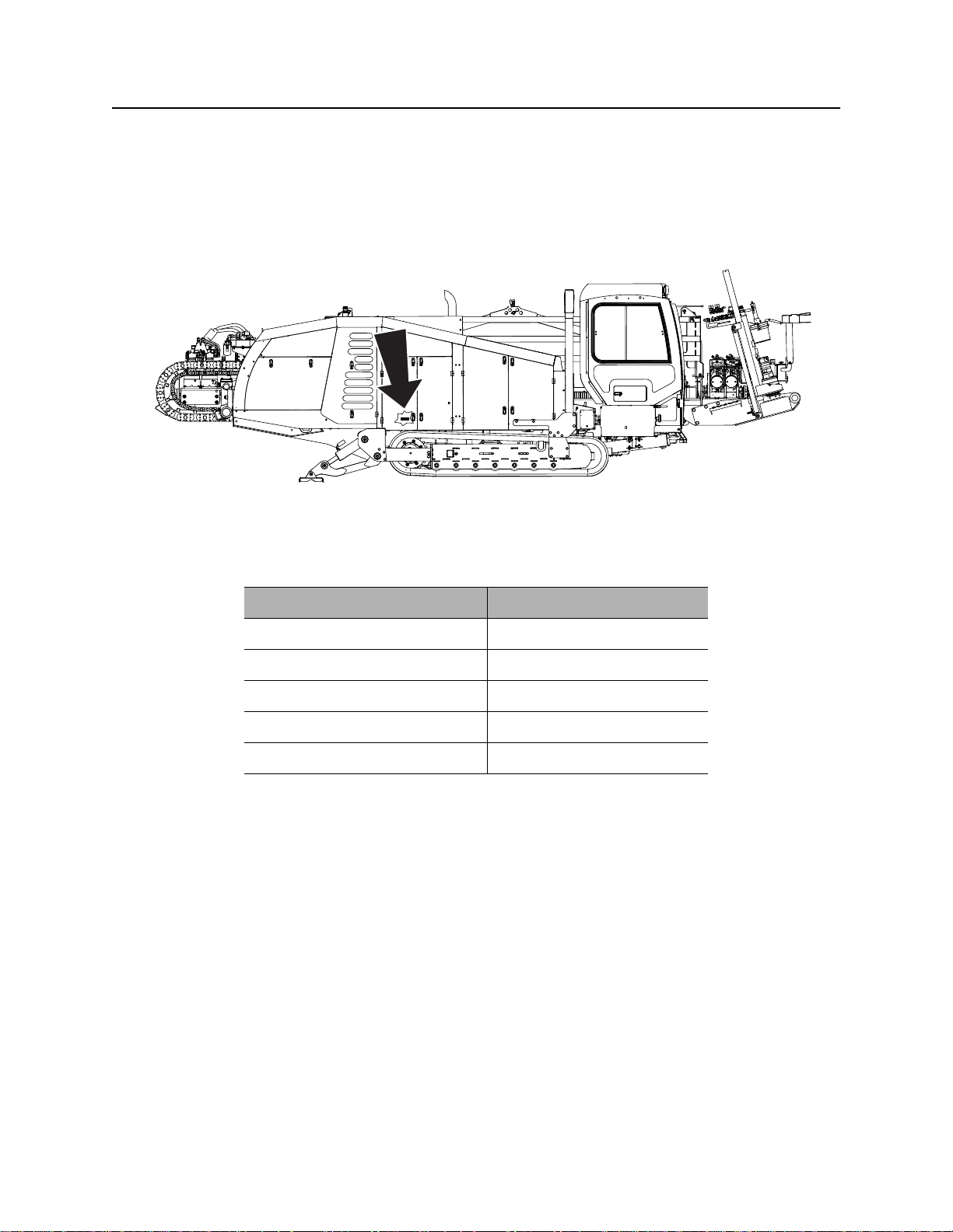
Serial Number Location
Serial Number Location
Record serial numbers and date of purchase in spaces provided. Drilling unit serial number is located as
shown.
j40om015w.eps
Item
Date of manufacture
Date of purchase
Drilling unit serial number
Engine serial number
Trailer serial number
Page 5

JT60/JT60 All Terrain Operator’s Manual Overview - 3
Intended Use
Intended Use
The JT60/All Terrain is a self-contained horizontal directional drilling unit capable of drilling through solid
rock, cobblestone, broken rock, gravel, and other soil/rock mixes, as well as less extreme soil conditions. It
is designed to install buried cable and pipe at distances to 1,000’ (300 m) depending on soil conditions.
The unit is designed for operation in temperatures typically experienced in earth moving and construction
work environments. Provisions may be required to operate in extreme temperatures. Contact your Ditch
Witch dealer.
The unit can be used with Ditch Witch drilling fluid units and Ditch Witch locating equipment. It should be
operated, serviced, and repaired only by persons familiar with its particular characteristics and acquainted
with the relevant safety procedures.
Use in any other way is considered contrary to the intended use.
Equipment Modification
This equipment was designed and built in accordance with applicable standards and regulations.
Modification of equipment could mean that it will no longer meet regulations and may not function properly
or in accordance with the operating instructions. Modification of equipment should only be made by
competent personnel possessing knowledge of applicable standards, regulations, equipment design
functionality/requirements and any required specialized testing.
The protection offered by the Rollover Protective System (ROPS) will be impaired if it has been subjected
to any modification, structural damage, or has been involved in an overturn accident. The ROPS must be
replaced after a roll-over.
Page 6
Overview - 4 JT60/JT60 All Terrain Operator’s Manual
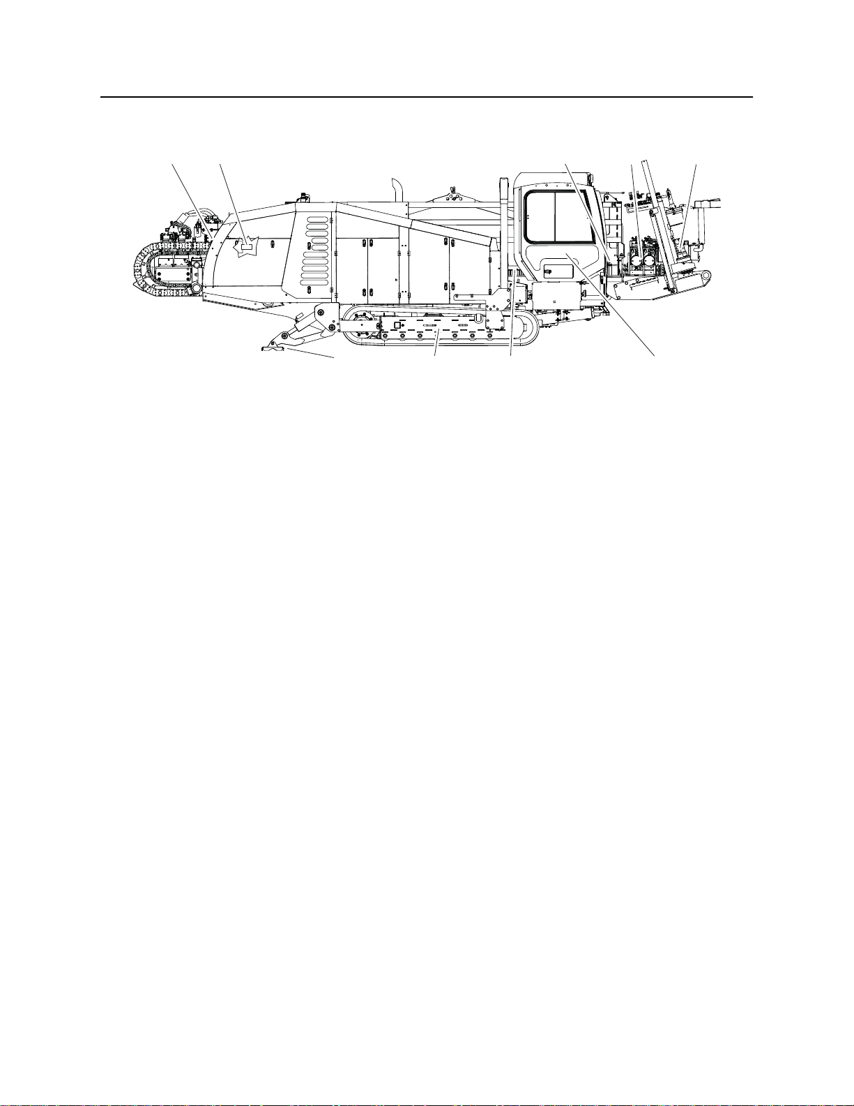
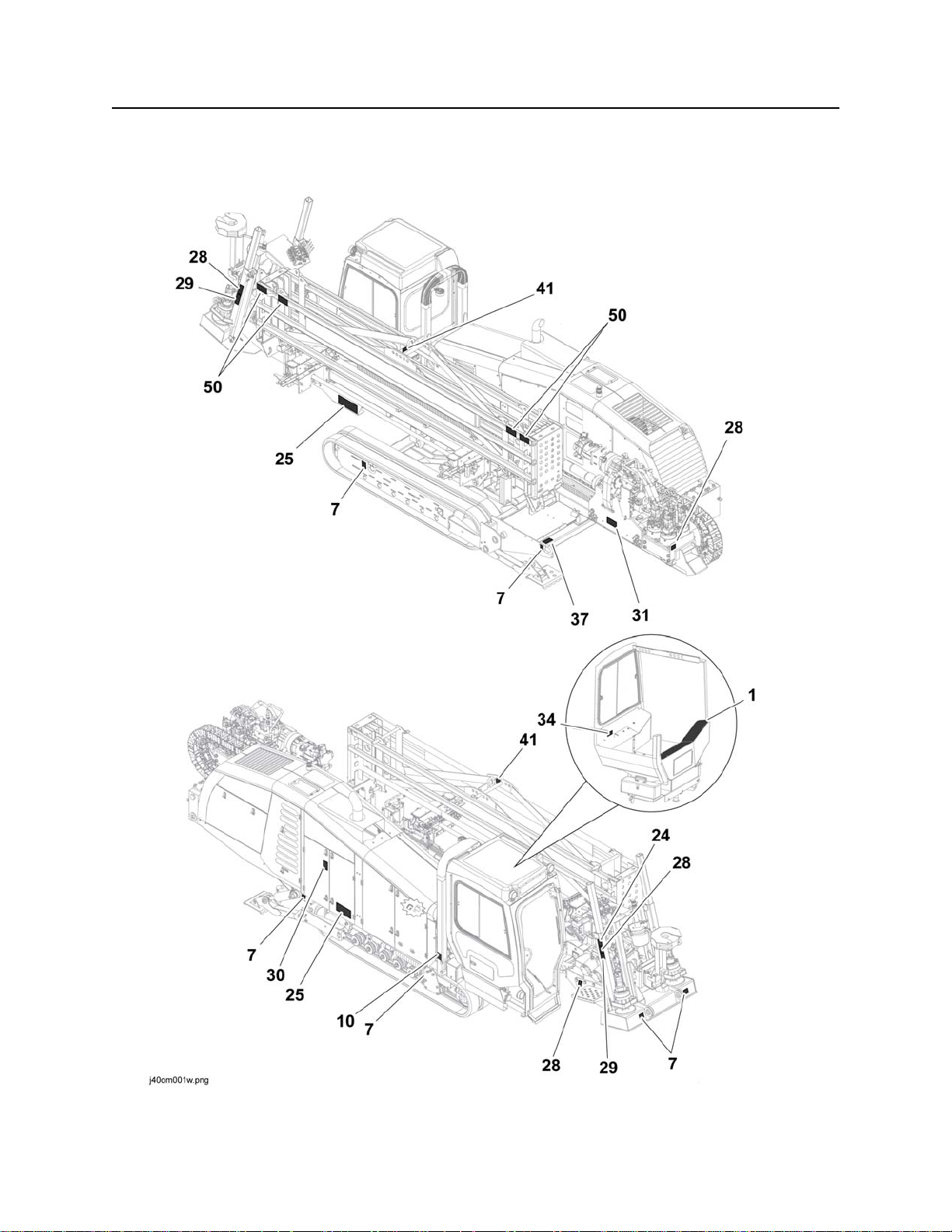
Unit Components
Unit Components
j40om016w.eps
1. Carriage
2. Spindle
3. Pipeloader
4. Vise wrenches
5. Anchoring system
312 4
798
6. Operator’s station
7. Drill frame
8. Tracks
9. Stabilizer
5
6
Page 7
JT60/JT60 All Terrain Operator’s Manual Overview - 5
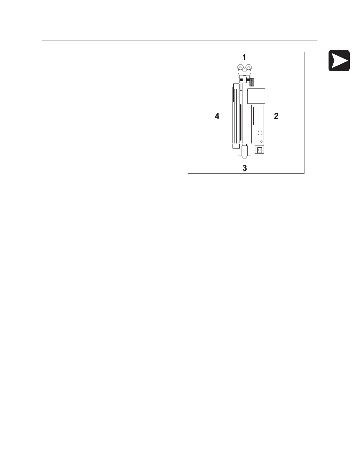
Operator Orientation
Operator Orientation
1. Front of unit
2. Right side of unit
3. Rear of unit
4. Left side of unit
j40om017w.eps
About This Manual
This manual contains information for the proper use of this machine. See the beige Operation Overview
pages for basic operating procedures. Cross references such as “See page 50” will direct you to detailed
procedures.
Bulleted Lists
Bulleted lists provide helpful or important information or contain procedures that do not have to be
performed in a specific order.
Numbered Lists
Numbered lists contain illustration callouts or list steps that must be performed in order.
Page 8

Overview - 6 JT60/JT60 All Terrain Operator’s Manual
About This Manual
Page 9

JT60/JT60 All Terrain Operator’s Manual Foreword - 7
Foreword
This manual is an important part of your equipment. It provides safety information and operation
instructions to help you use and maintain your Ditch Witch equipment.
Read this manual before using your equipment. Keep it with the equipment at all times for future reference.
If you sell your equipment, be sure to give this manual to the new owner.
If you need a replacement copy, contact your Ditch Witch dealer. If you need assistance in locating a
dealer, visit our website at www.ditchwitch.com or write to the following address:
The Charles Machine Works, Inc.
Attn: Marketing Department
PO Box 66
Perry, OK 73077-0066
USA
The descriptions and specifications in this manual are subject to change without notice. The Charles
Machine Works, Inc. reserves the right to improve equipment. Some product improvements may have
taken place after this manual was published. For the latest information on Ditch Witch equipment, see your
Ditch Witch dealer.
Thank you for buying and using Ditch Witch equipment.
Page 10

Foreword - 8 JT60/JT60 All Terrain Operator’s Manual
JT60/All Terrain
(Tier 4i)
Operator’s Manual
Issue number 2.0/OM-02/14
Part number 053-2547
Copyright 2013
by The Charles Machine Works, Inc.
, Ditch Witch, Jet Trac, Fluid Miser, Power Pipe, and CMW are registered
trademarks of The Charles Machine Works, Inc.
This product is covered by one or more of the following patents:
U.S. B1 4,858,704; 4,953,638; 5,148,880; 5,242,026; 5,341,887; 5,490,569; 5,684,466; 5,713,423; 5,794,719; 5,880,680; 5,941,322;
6,085,852; 6,109,371; 6,179,065; 6,216,803; 6,250,403; 6,250,404; 6,290,606; 6,311,790; 6,411,094; 6,543,551; 6,550,547;
6,672,409; 6,739,413; 6,761,231; 6,776,246; 6,808,210; 6,827,158; 6,848,506; 6,871,712; RE37,450; RE37,923; RE37,975;
RE38,418; AU 689,533; 706,544; 718,034; 755,862; CA 2,156,398; 2,217,899; DE 694 17 019; 695 29 634; 297 01 406;
EP 0683845; 0674093; 0817901; 0846841; 0927892; FR 674,093; GB 2,309,239; 2,312,006; EP674,093; EP846,841; JP 3,458,247;
other U.S. and foreign patents pending.
Page 11

JT60/JT60 All Terrain Operator’s Manual Safety - 11
Safety
Chapter Contents
Guidelines . . . . . . . . . . . . . . . . . . . . . . . . . . . . . . . . 12
Emergency Procedures . . . . . . . . . . . . . . . . . . . . . 13
• Electric Strike Description. . . . . . . . . . . . . . . . . . . . . . . . . . . . . . . . . . . 13
• If an Electric Line is Damaged . . . . . . . . . . . . . . . . . . . . . . . . . . . . . . . 14
• If a Gas Line is Damaged . . . . . . . . . . . . . . . . . . . . . . . . . . . . . . . . . . . 15
• If a Fiber Optic Cable is Damaged . . . . . . . . . . . . . . . . . . . . . . . . . . . . 16
• If Machine Catches on Fire. . . . . . . . . . . . . . . . . . . . . . . . . . . . . . . . . . 16
Safety Alert Classifications . . . . . . . . . . . . . . . . . . 21
Machine Safety Alerts . . . . . . . . . . . . . . . . . . . . . . 22
Attachment Safety Alerts . . . . . . . . . . . . . . . . . . . 25
CMW®
Page 12

Safety - 12 JT60/JT60 All Terrain Operator’s Manual
Guidelines
Guidelines
Follow these guidelines before operating any jobsite equipment:
• Complete proper training and read operator’s manual before using equipment.
• Contact your local One-Call (811 in USA) or the One-Call referral number (888-258-0808 in USA and
Canada) to have underground utilities located before digging. Also contact any utilities that do not
participate in the One-Call service. Mark proposed path with white paint prior to contacting One-Call or
utilities.
• Classify jobsite based on its hazards and use correct tools and machinery, safety equipment, and work
methods for jobsite.
• Mark jobsite clearly and keep spectators away.
• Wear personal protective equipment.
• Review jobsite hazards, safety and emergency procedures, and individual responsibilities with all
personnel before work begins. Safety videos are available from your Ditch Witch
• Replace missing or damaged safety shields and safety signs.
• Use equipment carefully. Stop operation and investigate anything that does not look or feel right.
®
dealer.
• Do not operate unit where flammable gas may be present.
• Contact your Ditch Witch dealer if you have any question about operation, maintenance, or equipment
use.
• Complete the equipment checklist located at www.ditchwitch.com/resources/safety.
CMW®
Page 13
JT60/JT60 All Terrain Operator’s Manual Safety - 13
Emergency Procedures
Emergency Procedures
Jobsite hazards could cause death or serious injury. Use
correct equipment and work methods. Use and maintain proper safety
equipment.
Before operating any equipment, review emergency procedures and check that all safety precautions have
been taken.
EMERGENCY SHUTDOWN - Turn ignition switch to stop position or push remote engine stop button (if
equipped).
Electric Strike Description
Electric shock. Contacting electric lines will cause death or serious injury.
Know location of lines and stay away.
When working near electric cables, remember the following:
• Electricity follows all paths to ground, not just path of least resistance.
• Pipes, hoses, and cables will conduct electricity back to all equipment.
• Low voltage current can injure or kill. Many work-related electrocutions result from contact with less
than 440 volts.
Most electric strikes are not noticeable, but indications of a strike include:
• power outage
• smoke
• explosion
• popping noises
• arcing electricity
If any of these occur, or if strike alarm sounds or flashes, assume an electric strike has occurred.
CMW®
Page 14

Safety - 14 JT60/JT60 All Terrain Operator’s Manual
Emergency Procedures
If an Electric Line is Damaged
If you suspect an electric line has been damaged and you are on drilling unit or bonded equipment, DO
NOT MOVE. Remain on drilling machine and take the following actions. The order and degree of action will
depend on the situation.
• Warn people nearby that an electric strike has occurred.
• Have someone contact electric company.
• Reverse drilling direction and try to break contact. Do not touch drill pipe with hands or hand-held
tools.
• Press electric strike system self test button.
• If alarm sounds again, stay where you are and wait for electric company to shut off power.
• If alarm does not sound and there is no other indication of a strike, wait at least one full minute
before moving away from equipment. Utility might use automatic reclosers which will restart
current flow. If alarm sounds again while waiting, stay where you are until electric company shuts
off power.
• If alarm does not sound but all lights in strike indicator are on, assume strike is continuing and stay
where you are until electric company shuts off power.
• Do not resume drilling or allow anyone into area until given permission by electric company.
If you suspect an electric line has been damaged and you are off drilling unit or bonded equipment, DO
NOT TOUCH ANY EQUIPMENT connected to drilling unit. Take the following actions. The order and
degree of action will depend on the situation.
• Stay where you are unless you are wearing electric insulating boots. If you leave, do not return to area
or allow anyone into area until given permission by electric company.
CMW®
Page 15

JT60/JT60 All Terrain Operator’s Manual Safety - 15
Emergency Procedures
If a Gas Line is Damaged
Fire or explosion possible. Fumes could ignite and cause
burns. No smoking, no flame, no spark.
Explosion possible. Serious injury or equipment damage could occur.
Follow directions carefully.
If you suspect a gas line has been damaged, take the following actions. The order and degree of action will
depend on the situation.
• Immediately shut off engine(s), if this can be done safely and quickly.
• Remove any ignition source(s), if this can be done safely and quickly.
• Warn others that a gas line has been cut and that they should leave the area.
• Leave jobsite as quickly as possible.
• Immediately call your local emergency phone number and utility company.
• If jobsite is along street, stop traffic from driving near jobsite.
• Do not return to jobsite until given permission by emergency personnel and utility company.
CMW®
Page 16

Safety - 16 JT60/JT60 All Terrain Operator’s Manual
Emergency Procedures
If a Fiber Optic Cable is Damaged
Do not look into cut ends of fiber optic or unidentified cable. Vision damage can occur. Contact utility
company.
If Machine Catches on Fire
Perform emergency shutdown procedure and then take the following actions. The order and degree of
action will depend on the situation.
• Immediately move battery disconnect switch (if equipped and accessible) to disconnect position.
• If fire is small and fire extinguisher is available, attempt to extinguish fire.
• If fire cannot be extinguished, leave area as quickly as possible and contact emergency personnel.
CMW®
Page 17

JT60/JT60 All Terrainn Operator’s Manual Safety - 17
Safety Alert Classifications
Safety Alert Classifications
These classifications and the icons defined on the following pages work together to alert you to situations
which could be harmful to you, jobsite bystanders or your equipment. When you see these words and
icons in the book or on the machine, carefully read and follow all instructions. YOUR SAFETY IS AT
STAKE.
Watch for the three safety alert levels: DANGER, WARNING and CAUTION. Learn what each level
means.
indicates a hazardous situation that, if not avoided, will result in death or serious injury.
This signal word is to be limited to the most extreme situations.
indicates a hazardous situation that, if not avoided, could result in death or serious injury.
indicates a hazardous situation that, if not avoided, could result in minor or moderate
injury.
Watch for two other words: NOTICE and IMPORTANT.
NOTICE indicates information considered important, but not hazard-related (e.g., messages relating to
property damage).
IMPORTANT can help you do a better job or make your job easier in some way.
CMW®
Page 18
Safety - 18 JT60/JT60 All Terrain Operator’s Manual
Machine Safety Alerts
Machine Safety Alerts
CMW®
Page 19
JT60/JT60 All Terrainn Operator’s Manual Safety - 19
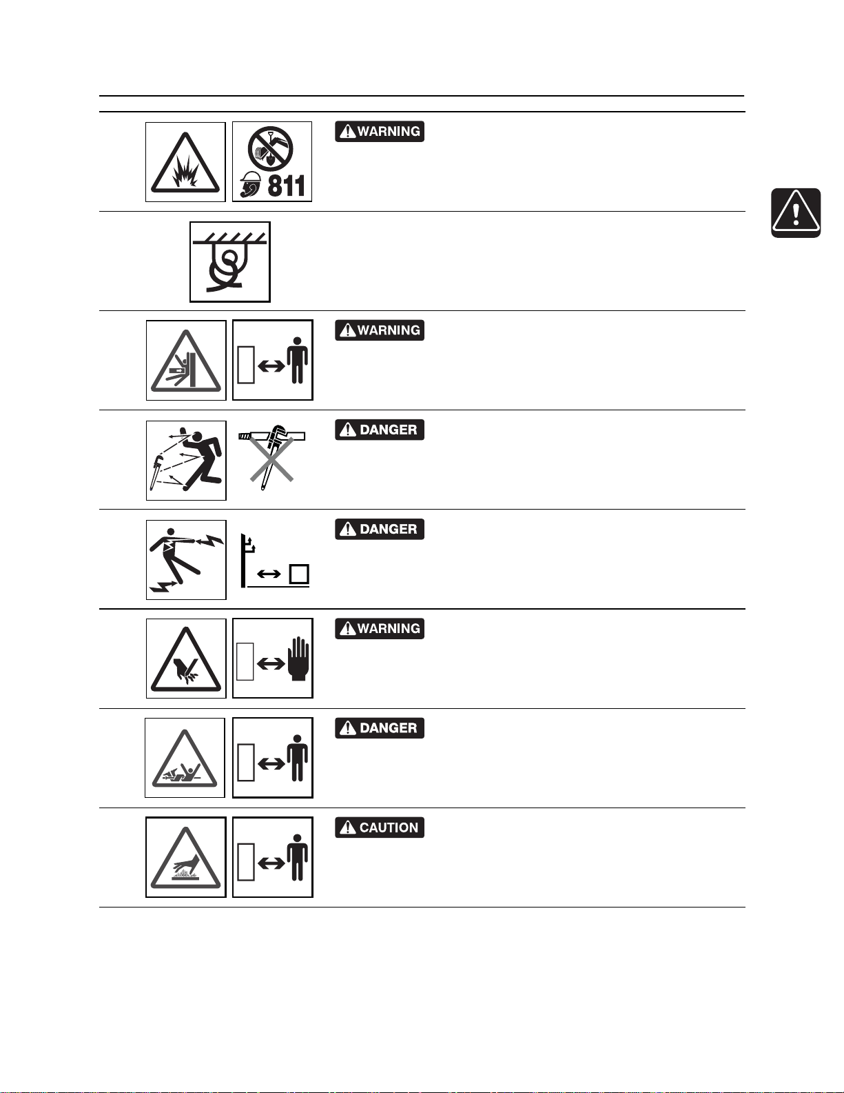
Machine Safety Alerts
Jobsite hazards could cause death or serious
1
7
10
24
injury. Use correct equipment and work methods. Use and maintain
proper safety equipment.
Tiedown location. See Transport chapter for more information.
Crushing weight could cause death or serious
injury. Use proper procedures and equipment or stay away.
Moving tools will kill or injure. Shut off drill string
power when anyone can be struck by moving or thrown tools.
Never use pipe wrenches on drill string.
25
28
29
30
Electric shock. Contacting electric lines will cause
death or serious injury. Know location of lines and stay away.
Moving parts could cut off hand or foot. Stay away.
Turning shaft will kill you or crush arm or leg. Stay
away.
Hot parts may cause burns. Do not touch until cool
or wear gloves.
CMW®
Page 20
Safety - 20 JT60/JT60 All Terrain Operator’s Manual
Machine Safety Alerts
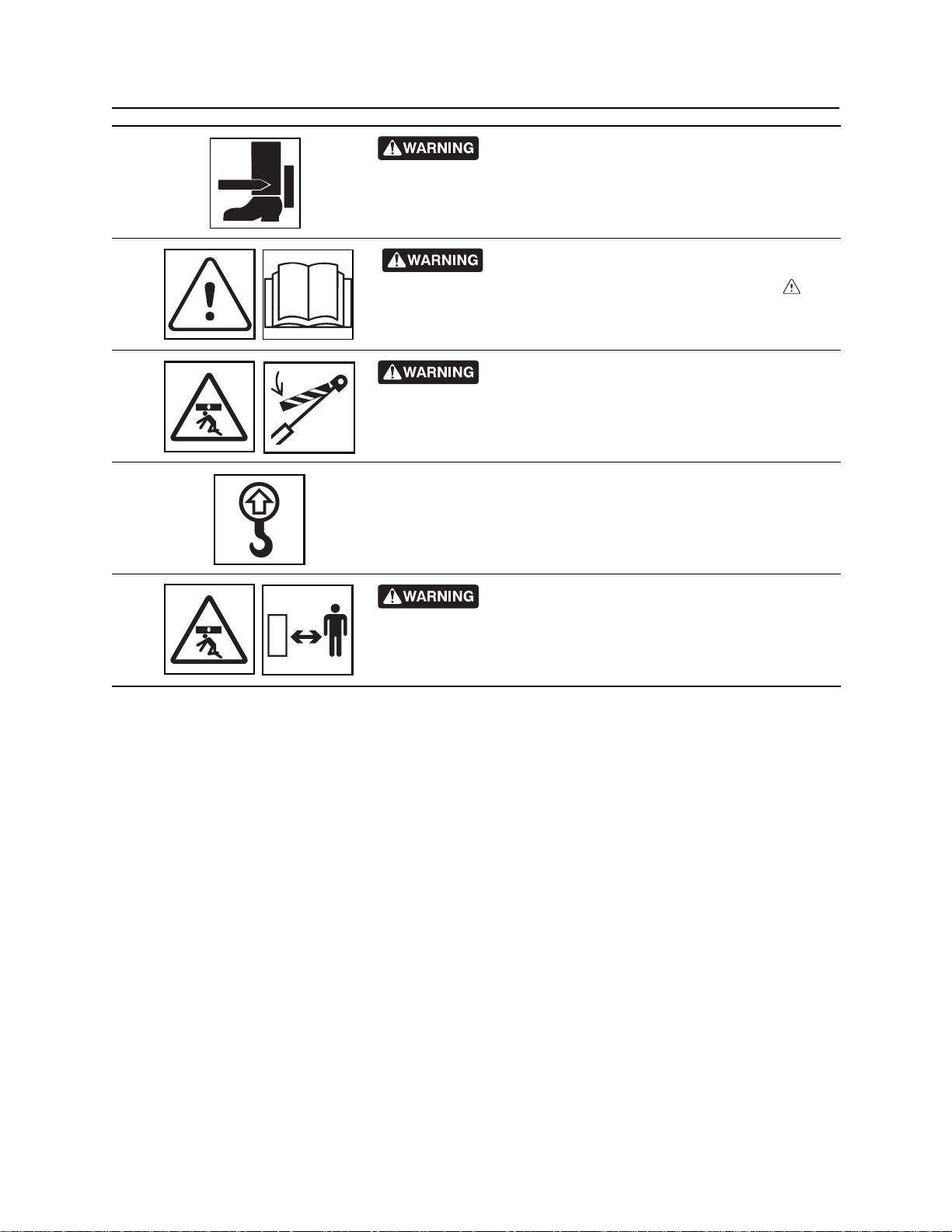
Moving parts could cut off hand or foot. Stay away.
31
Read operator’s manual. Know how to use all
34
37
41
50
controls before operating machine. When you see this sign on
the machine or in the manual, read it and use caution. Your safety
is at stake.
Moving parts can crush. Secure extended cylinder
with locking device before servicing.
Lift point. See Transport chapter for more information.
Crushing weight could cause death or serious
injury. Use proper procedures and equipment or stay away.
CMW®
Page 21

JT60/JT60 All Terrain Operator’s Manual Controls - 21
Controls
Chapter Contents
Set-Up Controls. . . . . . . . . . . . . . . . . . . . . . . . . . . . 22
Anchor System Console . . . . . . . . . . . . . . . . . . . . 25
Left Control Console . . . . . . . . . . . . . . . . . . . . . . . 27
• Engine Display . . . . . . . . . . . . . . . . . . . . . . . . . . . . . . . . . . . . . . . . . . . 27
• ESID Strike Display. . . . . . . . . . . . . . . . . . . . . . . . . . . . . . . . . . . . . . . . 30
• ESID Application Display . . . . . . . . . . . . . . . . . . . . . . . . . . . . . . . . . . . 31
• Drilling Controls . . . . . . . . . . . . . . . . . . . . . . . . . . . . . . . . . . . . . . . . . . 32
• Wrench Joystick Control . . . . . . . . . . . . . . . . . . . . . . . . . . . . . . . . . . . . 36
Right Control Console . . . . . . . . . . . . . . . . . . . . . . 39
• Operation Controls . . . . . . . . . . . . . . . . . . . . . . . . . . . . . . . . . . . . . . . . 39
• Gauges and Indicators . . . . . . . . . . . . . . . . . . . . . . . . . . . . . . . . . . . . . 41
• Drill/Drive Joystick. . . . . . . . . . . . . . . . . . . . . . . . . . . . . . . . . . . . . . . . . 44
Seat . . . . . . . . . . . . . . . . . . . . . . . . . . . . . . . . . . . . . 46
Cab Controls . . . . . . . . . . . . . . . . . . . . . . . . . . . . . . 47
Override Box . . . . . . . . . . . . . . . . . . . . . . . . . . . . . . 49
Battery . . . . . . . . . . . . . . . . . . . . . . . . . . . . . . . . . . . 51
Engine Compartment . . . . . . . . . . . . . . . . . . . . . . . 52
Rear Console. . . . . . . . . . . . . . . . . . . . . . . . . . . . . . 54
Page 22
Controls - 22 JT60/JT60 All Terrain Operator’s Manual
Setup Controls
Setup Controls
1234 5678
j40om002w.eps
1. Left stabilizer control
2. Right stabilizer control
3. Back frame tilt control
4. Front frame tilt control
Item Description Notes
1. Left stabilizer control To raise, push up.
To lower, pull down.
5. Washer fluid on/off switch
6. Upper wiper switch
7. Lower wiper switch
8. Worklight switch
IMPORTANT: Lower right and left
stabilizers to the ground together,
then adjust individually.
Page 23
JT60/JT60 All Terrain Operator’s Manual Controls - 23
Setup Controls
Item Description Notes
2. Right stabilizer control To raise, push up.
To lower, pull down.
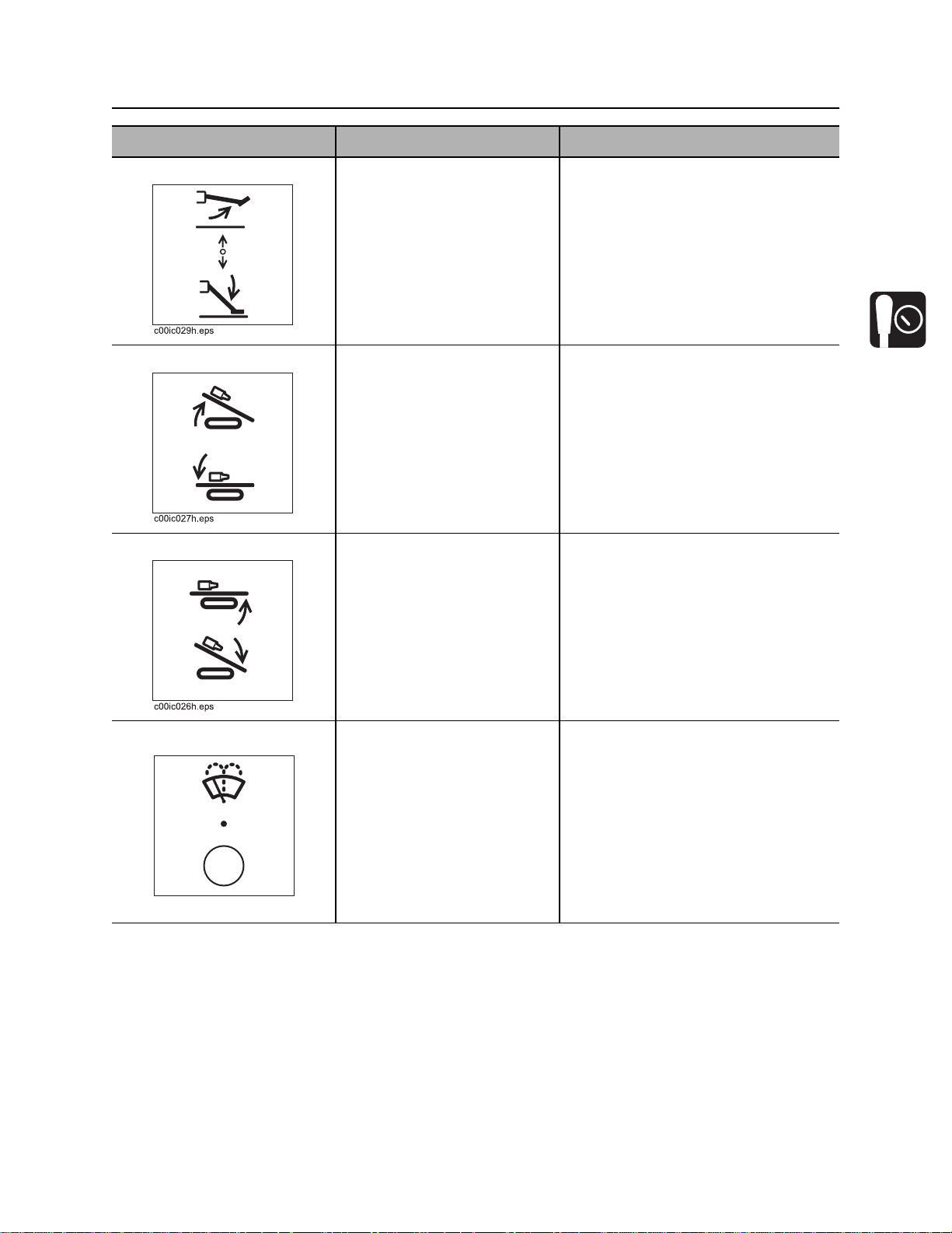
3. Back frame tilt control To raise, push up.
To lower, pull down.
4. Front frame tilt control To raise, push up.
To lower, pull down.
IMPORTANT: Lower left and right
stabilizers to the ground together,
then adjust individually.
IMPORTANT: To ensure a stable
platform for drilling, use front and
back tilt controls together to set frame
at desired pitch without raising tracks
off the ground.
IMPORTANT: To ensure a stable
platform for drilling, use front and
back tilt controls together to set frame
at desired pitch without raising tracks
off the ground.
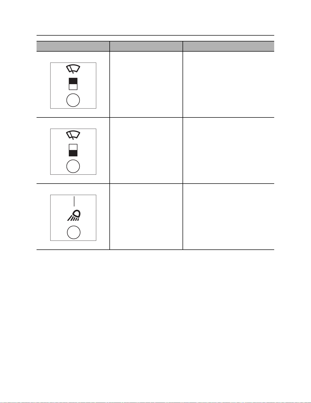
5. Washer on/off switch To start windshield washer
fluid, press and hold top.
To stop washer fluid flow,
release.
c00ic045w.eps
Page 24
Controls - 24 JT60/JT60 All Terrain Operator’s Manual
Setup Controls
Item Description Notes
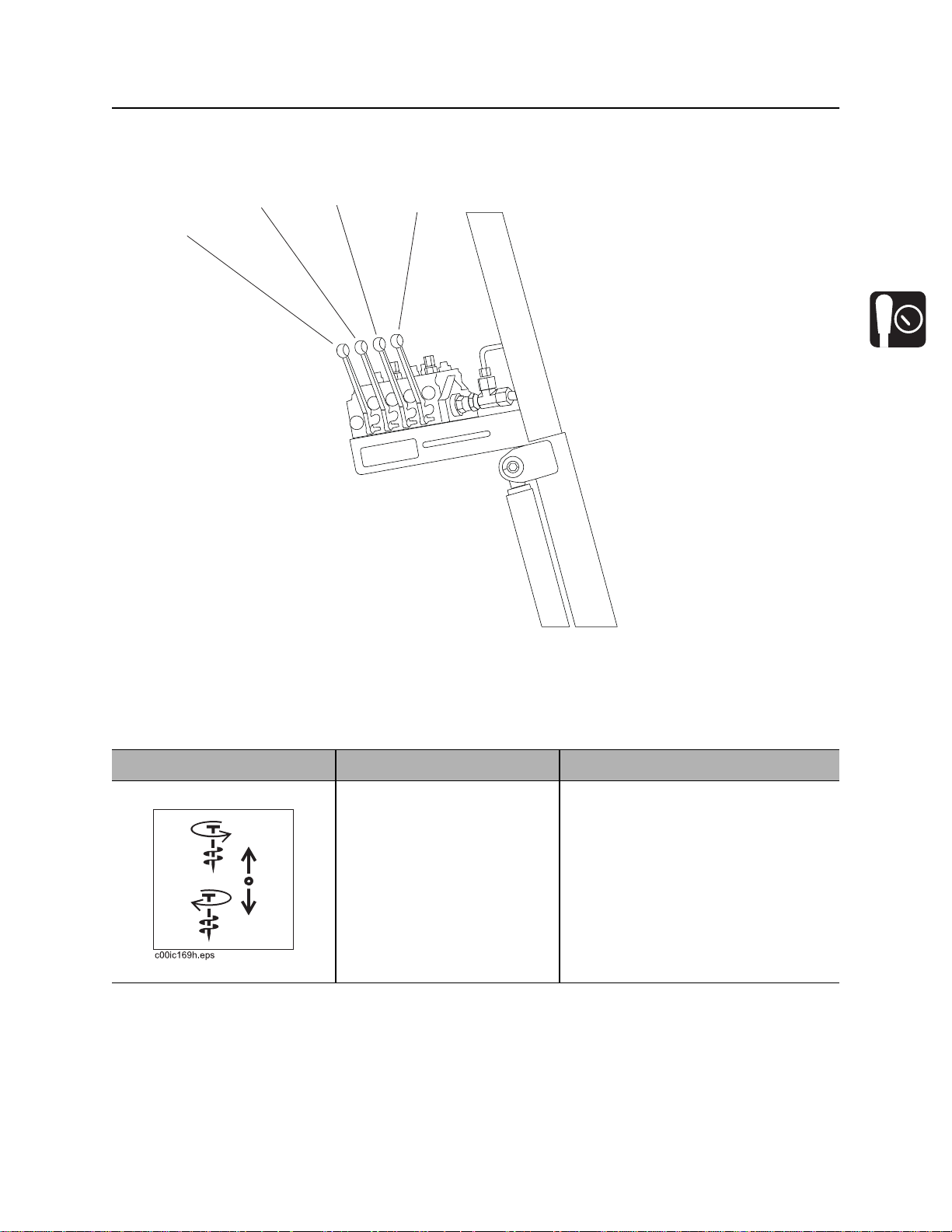
6. Upper wiper switch To start wiper blade, press
top.
To stop wiper blade, press
bottom.
c00ic046w.eps
7. Lower wiper switch To start wiper blade, press
top.
To stop wiper blade, press
bottom.
c00ic047w.eps
8. Worklight switch To turn on, press top.
To turn off, press bottom.
c00ic048w.eps
Page 25
JT60/JT60 All Terrain Operator’s Manual Controls - 25
Anchor System Console
Anchor System Console
1
j40om003w.eps
2
3
4
1. Left rotation control
2. Left thrust control
Item Description Notes
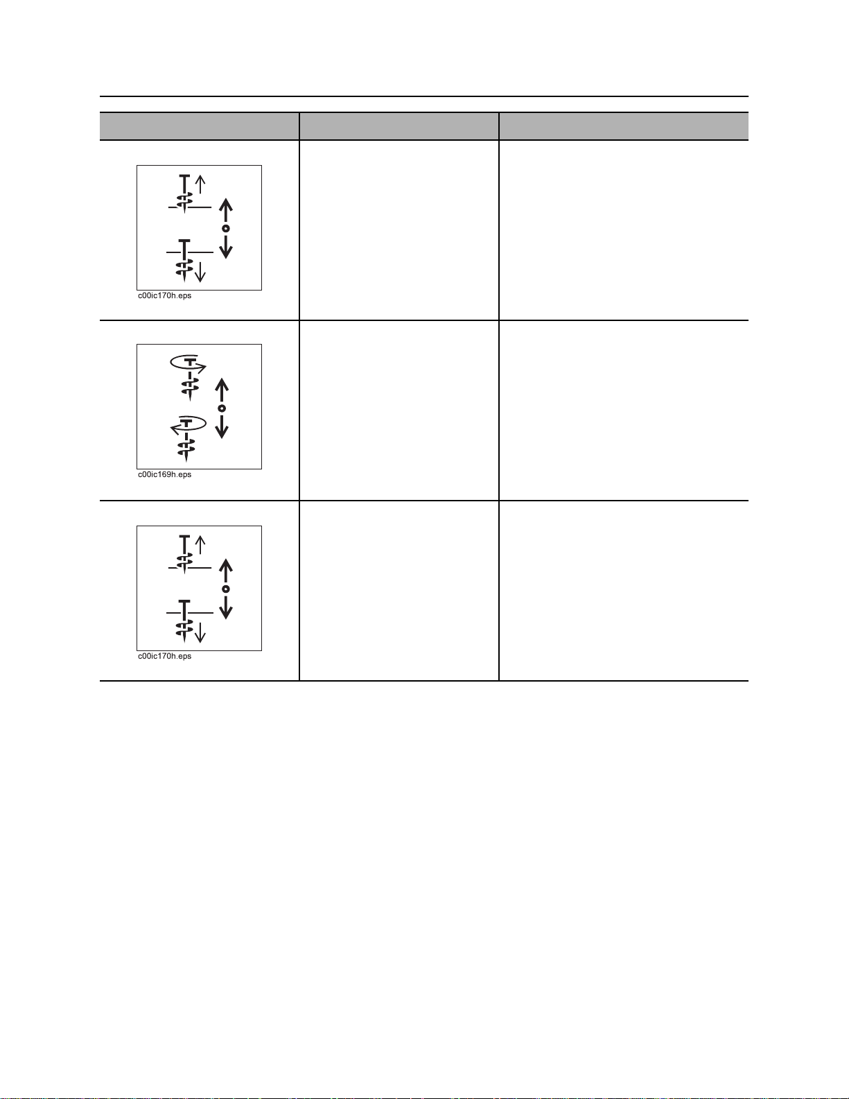
1. Left rotation control To remove anchor, pull.
To drive anchor, push.
3. Right rotation control
4. Right thrust control
See “Anchor System” on page 119.
Page 26
Controls - 26 JT60/JT60 All Terrain Operator’s Manual
Anchor System Console
Item Description Notes
2. Left thrust control To move anchor up, pull.
To move anchor down, push.
3. Right rotation control To remove anchor, pull.
To drive anchor, push.
4. Right thrust control To move anchor up, pull.
To move anchor down, push.
See “Anchor System” on page 119.
See “Anchor System” on page 119.
See “Anchor System” on page 119.
Page 27
JT60/JT60 All Terrain Operator’s Manual Controls - 27
Left Control Console
Left Control Console
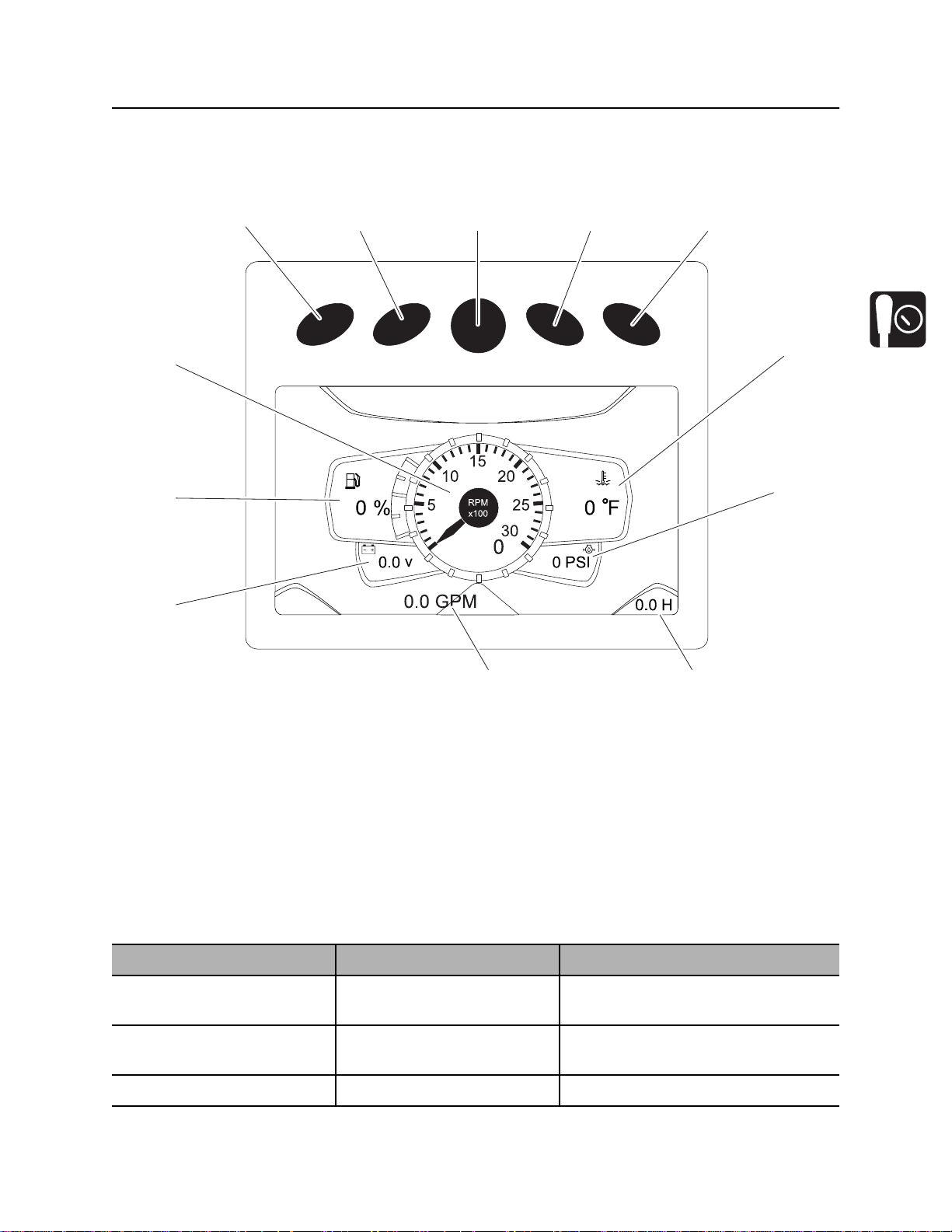
Engine Display
4
3
2
5678
9
10
1
j40om011w.eps
1112
1. Voltmeter display
2. Fuel level display
3. Tachometer
4. Soft key
5. Soft key
6. Main menu key
Item Description Notes
1. Voltmeter display Shows system voltage. Normal voltage is 13-14V with engine
2. Fuel level display Displays amount of fuel
remaining in tank.
3. Tachometer Displays engine speed.
7. Soft key
8. Soft key
9. Engine coolant temperature display
10. Engine oil pressure display
11. Hour meter
12. Drilling fluid flow display
running.
See “Approved Fuel” on page 172.
Page 28

Controls - 28 JT60/JT60 All Terrain Operator’s Manual
Left Control Console
Item Description Notes
4. Soft key Press to select a soft key
5. Soft key
6. Main menu key Press from main screen
7. Soft key Press to select a soft key
8. Soft key
9. Engine coolant
temperature display
10. Engine oil pressure
display
11. Hour meter Displays number of hours
12. Drilling fluid flow
display
Most engine display functions are self-explanatory. For more information about functions, see the
manufacturer’s instructions at www.fwmurphy.com.
command.
(gauges) to select main
menu.
command.
Displays engine coolant
temperature.
Displays engine oil pressure. Full load reading should be 45-70 psi
engine has been running.
Displays the estimated GPM
or LPM of drilling fluid being
pumped.
Soft key commands change with each
menu screen and are displayed next
to the key.
Soft key commands change with each
menu screen and are displayed next
to the key.
Normal coolant temperature is 160°212° F (71°-100° C).
(3.1-4.8 bar).
Main Menu
IMPORTANT: Soft key commands change with each menu screen and are displayed next to the key.
Item Description Notes
11. System settings key Press to select system
settings menu.
10. User settings key Press to select user settings
menu.
9. Main screen key Press to return to main
screen (gauges).
8. Engine diagnostics key Press to select engine
diagnostics menu.
System settings menu displays
information about the system.
Diagnostic information is only
available to dealer technicians.
User settings menu allows user to
change the language and unit
settings, and to set the time and date.
For dealer technician use only.
Page 29
JT60/JT60 All Terrain Operator’s Manual Controls - 29
Left Control Console
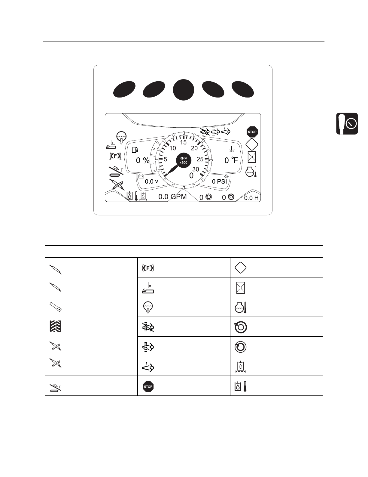
Status Indicators
!
R
j40om012w.eps
Indicators
JT drill mode active
JT
AT dirt mode active
ATd
AT rock drill mode active
ATr
Drive mode active
JT carve mode active
JT
AT dirt carve mode active
ATd
R
Front/Rear carriage
home
Front wrench closed Engine caution
!
Shuttle home
(shuttles retracted)
Drill fluid on Engine warm-up
DPF Regen inhibited
See engine manual
DPF Regen indicator
See engine manual.
High exhaust
temperature
Engine stop High hydraulic
Wait to start
protection
Outer rotation speed
Inner rotation speed
Hydraulic filter restriction
temperature
Page 30
Controls - 30 JT60/JT60 All Terrain Operator’s Manual
Left Control Console
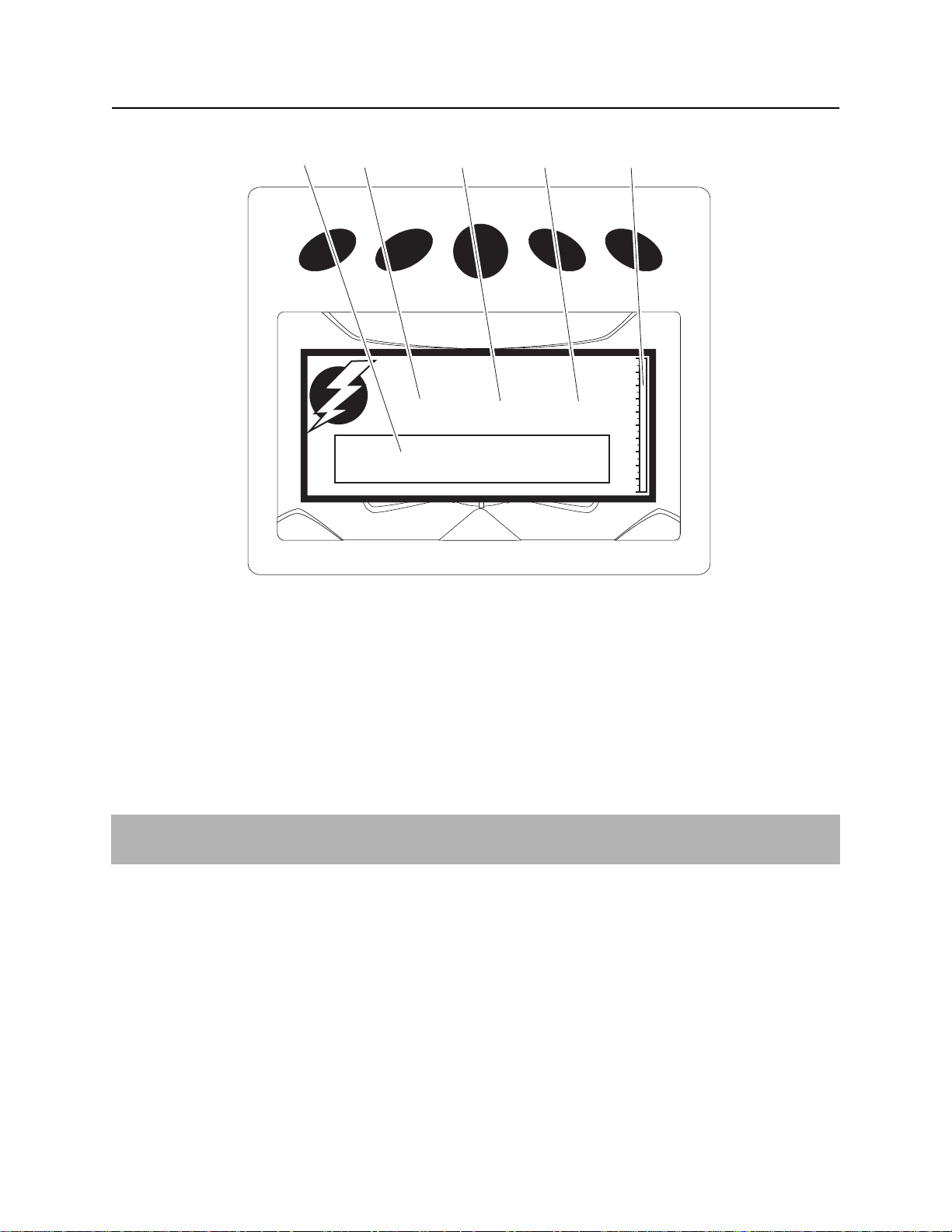
ESID Strike Display
12 3 4 5
STRIKEDETECTED
!! DO NOT EXIT THE MACHINE!!
0 % V 0 % A 0 % ESID
Instructions
j40om013w.eps
1. Instruction display
2. Voltage indicator
3. Current indicator
The above screen is displayed when an electrical strike is detected. Follow the instructions on the screen.
For more information, See “Electric Strike System” on page 123.
IMPORTANT: The ESID does not indicate proximity to electric lines. System will activate only when
voltage and/or amperage detected at the drilling unit are above threshold minimum limits.
4. Strike condition
5. Percentage of strike indicator
Page 31
JT60/JT60 All Terrain Operator’s Manual Controls - 31
Left Control Console
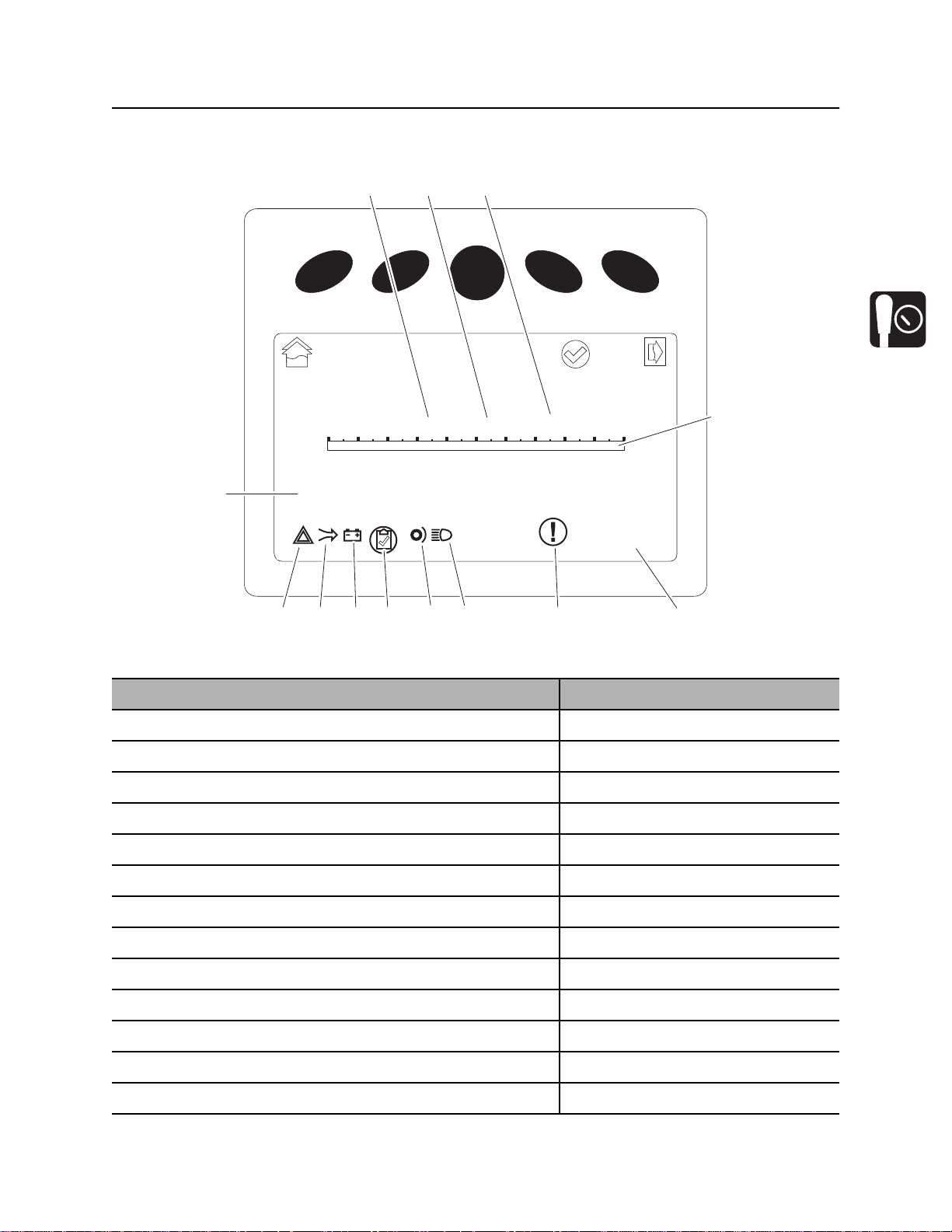
ESID Application Display
123
ACK
Errors
stored 0 errors
6
j40om014w.eps
13
Exit
ESID
0 % V 0 % A 0 % ESID
ESID_message
7
Item Description Notes
1. Voltage % of strike threshold
2. Amperage % of strike threshold
3. Combined % of strike threshold
4. Graphical display of electrical strike percentage
More
4
589101112
5. ESID stored error count
6. ESID error code indicator
7. ESID strobe active indicator
8. ESID horn active indicator
9. ESID test indicator
10. ESID voltage indicator
11. ESID amperage indicator
12. ESID okay (check) indicator
13. ESID message display
Page 32

Controls - 32 JT60/JT60 All Terrain Operator’s Manual
Left Control Console
Drilling Controls
5
6
7
8
9
4
3
2
10
1
11
j40om004w.eps
1. Engine throttle switch
2. Add pipe/manual/remove pipe switch
3. Pipe shuttle stop switch
4. Drilling fluid flow control
5. Auto Carve Switch
6. Carve window / inner rotation control
Item Description Notes
1. Engine throttle switch To increase speed, press
right.
To decrease speed, press
left.
To further increase or
decrease speed, press
c00ic059w.eps
additional times.
7. Outer rotation speed control
8. Spindle brake switch
9. Inner spindle switch
10. Manual inner rotation switch
11. ESID alarm interrupt / ESID self-test switch
Autothrottle mode slows the engine to
low throttle after 15 seconds of
inactivity involving thrust, rotation,
drilling fluid flow, or pipeloader
functions. To return to high speed,
activate thrust, rotation, drilling fluid,
or an add/remove pipe cycle.
Page 33

JT60/JT60 All Terrain Operator’s Manual Controls - 33
Left Control Console
Item Description Notes
2. Add pipe/manual/
remove pipe switch
To select “add pipe”
automated pipeloader
function, press right.
To use manual pipeloader
controls, move to center.
To select “remove pipe”
automated pipeloader
c00ic058w.eps
function, press left.
3. Pipe shuttle stop switch To lower shuttle stop, press
right.
To raise shuttle stop, press
left.
c00ic057w.eps
4. Drilling fluid flow
control
To increase flow, turn
clockwise.
To decrease flow, turn
counterclockwise.
See “Add Pipe” on page 104.
See “Remove Pipe” on page 114.
IMPORTANT: Look at pipe row
indicator on drill frame to see which
row shuttles will stop under.
c00ic056w.eps
5. AutoCarve switch To enable autocarve, press
left.
To deactivate autocarve,
press right.
c00ic055w.eps
Two-speed thrust is not allowed in
autocarve mode.
Page 34
Controls - 34 JT60/JT60 All Terrain Operator’s Manual
Left Control Console
Item Description Notes
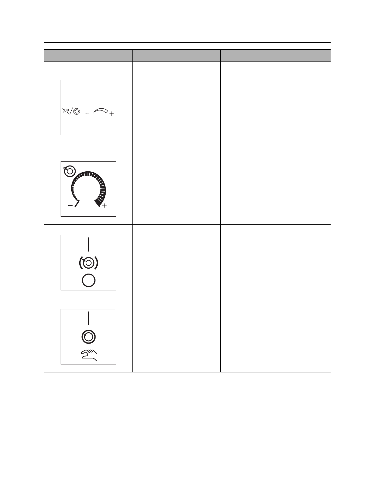
6. Carve window / inner
To increase, turn clockwise.
rotation speed control
To decrease, turn
counterclockwise.
c00ic053w.eps
7. Outer rotation speed
control
To increase outer rotation
maximum speed above 75
rpm, turn clockwise.
To decrease outer rotation
maximum speed toward 75
rpm, turn counterclockwise.
c00ic052w.eps
8. Spindle brake switch To engage, press top.
To disengage, press bottom.
See “Use AutoCarve” on page 108.
IMPORTANT: Unless outer rotation
speeds greater than 75 rpm are
needed, keep knob turned fully
counterclockwise to maintain full
torque.
IMPORTANT: Use when steering in
rock.
c00ic049w.eps
9. Inner spindle switch To turn on, press top.
To turn off, move to center.
To manually dither, press
bottom and control dither with
the manual inner rotation
switch.
c00ic050w.eps
IMPORTANT: To restart inner rotation
after operator has left seat, turn inner
rotation off and then on.
Page 35

JT60/JT60 All Terrain Operator’s Manual Controls - 35
Left Control Console
Item Description Notes
10. Manual inner rotation
control
c00ic051w.eps
11. ESID Alarm interrupt /
self test button
To rotate clockwise, move to
top.
To rotate counterclockwise,
move to bottom.
To stop inner rotation,
release.
To turn off strike alarm at
drilling unit, press top.
To start manual self test,
press bottom.
To reset system after a strike
has been detected, press
bottom.
IMPORTANT:
• Inner spindle control must be in
manual position for this control to
work.
• Range of speed is reduced to
allow easier manual control.
• Up/down paddle is spring
centered. Moving it above center
rotates inner rod clockwise.
Moving it further rotates the rod
faster. Moving it below center
does the same for counter
clockwise rotation.
Self test checks all systems and
circuits except voltage limiter.
IMPORTANT: See “If an Electric Line
is Damaged” on page 14.
c00ic054w.eps
Page 36

Controls - 36 JT60/JT60 All Terrain Operator’s Manual
Left Control Console
Wrench Control
4
3
2
5
1
6
7
j40om005w.eps
1. Wrench control
2. Wrench rotate
3. Pipe gripper switch
4. Pipe shuttle switch
Item Description Notes
1. Wrench control To clamp rear wrench, push
forward.
To unclamp rear wrench, pull
back.
To clamp front wrench, move
to right.
c00ic612h.eps
To unclamp front wrench,
move to left.
5. Pipe lift switch
6. Pipe lubricator switch
7. Set/Resume switch
Page 37

JT60/JT60 All Terrain Operator’s Manual Controls - 37
Left Control Console
Item Description Notes
2. Rear wrench rotation
switch
3. Pipe gripper switch To close, press top.
4. Pipe shuttle switch To move toward pipe box,
To rotate counterclockwise,
press top.
To rotate clockwise, press
bottom.
To stop rotation, release.
To open, press bottom.
press top.
To move toward spindle,
press bottom.
5. Pipe lift switch To raise, press top.
To lower, press bottom.
6. Pipe lubricator switch To apply joint compound,
press.
c00ic616h.eps
Page 38

Controls - 38 JT60/JT60 All Terrain Operator’s Manual
Left Control Console
Item Description Notes
7. Set/Resume switch To resume operation or
increase operation levels,
press top.
To set operating conditions or
reduce operation levels,
press bottom.
See “Cruise Control” on page 154.
See “Use AutoCarve” on page 108.
Page 39
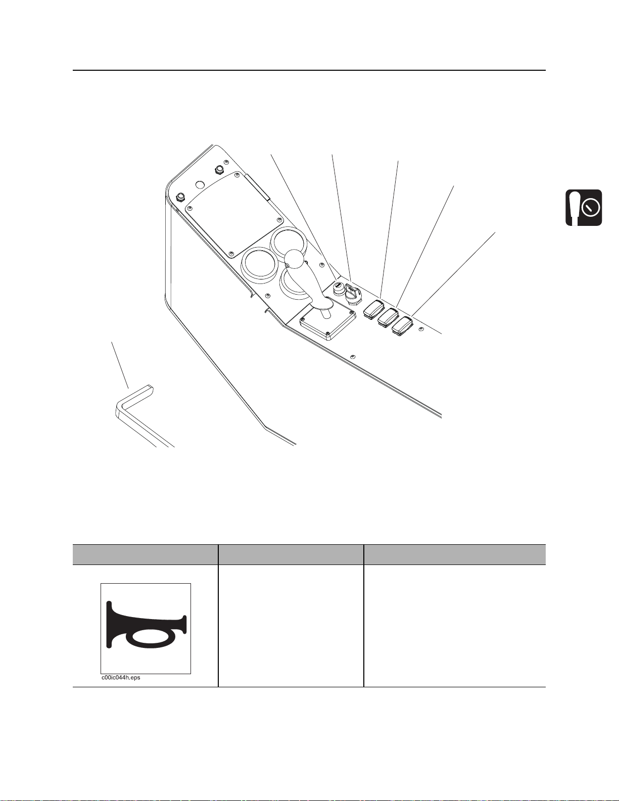
JT60/JT60 All Terrain Operator’s Manual Controls - 39
Right Control Console
Right Control Console
Operation Controls
12
3
4
5
6
j40om006w.eps
1. Horn button
2. Ignition switch
3. Drill/Park/Drive switch
Item Description Notes
1. Horn To sound horn, press.
4. Cab pivot control switch
5. Fluid flow control
6. Cab pivot lock
Page 40

Controls - 40 JT60/JT60 All Terrain Operator’s Manual
Right Control Console
Item Description Notes
2. Ignition switch To start engine, insert key and
turn clockwise.
To stop engine, turn key
counterclockwise.
3. Drill/Park/Drive switch To drill, press left.
To set parking brake, move to
center.
To drive, press right.
c00ic060w.eps
4. Cab pivot control
switch
To pivot into drilling position,
lift pivot lock and press left.
To pivot into driving position,
press right.
5. Fluid flow control To increase flow, turn
clockwise.
To decrease flow, turn
counterclockwise.
IMPORTANT:
• Lighted icon on engine display
indicates unit is ready to perform
that function.
• Cab must be in the correct
position for drill or drive.
c00ic061w.eps
6. Cab pivot lock To unlock, lift and hold while
pivoting cab into drilling
position.
Control will lock when cab
reaches driving position.
Page 41
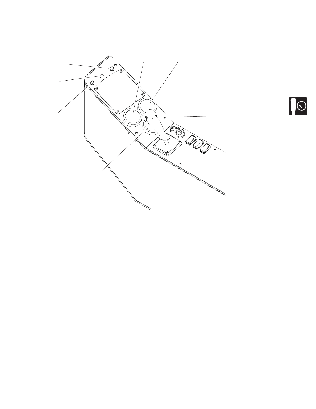
JT60/JT60 All Terrain Operator’s Manual Controls - 41
Right Control Console
Gauges and Indicators
45
3
2
1
6
j40om007w.eps
1. Diagnostic indicator (red)
2. Control cycle indicator (green)
3. Thrust pressure gauge
4. Rotation pressure gauge
7
5. Drilling fluid pressure gauge
6. Drilling fluid pump indicator (red)
7. Drilling fluid pump status indicator (red)
Page 42

Controls - 42 JT60/JT60 All Terrain Operator’s Manual
Right Control Console
Item Description Notes
1. Diagnostic indicator
(red)
!
c00ic062w.eps
2. EDT Port Connection for Electronic
3. Control cycle indicator
(green)
If system is OK, light should
be off.
If system may not be getting
power, light should be on.
If a non-essential diagnostic
code is recorded, light should
flash on and off for 10
seconds.
If an essential diagnostic
code is recorded, light should
flash on for three seconds
and off for half a second.
Diagnostic Tool.
If nothing is being controlled,
light should be off.
If system is waiting for an
action before starting cycle,
light should flash on and off.
See “Wireline Tracking” on page 156.
For use by qualified Ditch Witch
technicians.
If something is being
controlled, light should be on.
If control cycle is interrupted,
light should flash twice
quickly.
4. Thrust pressure gauge Displays hydraulic fluid
pressure to thrust motor
during thrust and pullback.
Page 43
JT60/JT60 All Terrain Operator’s Manual Controls - 43
Right Control Console
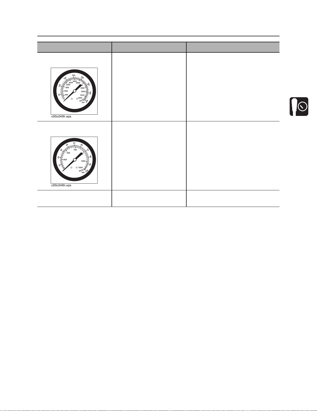
Item Description Notes
5. Rotation pressure
gauge
6. Drilling fluid pressure
gauge
7. Drilling fluid pump
status indicator (red)
Displays hydraulic fluid
pressure to rotation motor
when spindle is turned
clockwise.
Displays drilling fluid pressure
in the drilling fluid hard line.
Lights when pump is on.
Inner rotation pressure is displayed
when inner rotation is on and front
wrench is open.
Outer rotation pressure is displayed
when front wrench is closed and
during backreaming.
IMPORTANT: Monitor this gauge and
drilling fluid flowmeter carefully to see
if values are rising or falling at the
same time. If they are not, nozzle
might be plugged.
Page 44

Controls - 44 JT60/JT60 All Terrain Operator’s Manual
Right Control Console
Drill/Drive Control
3
4
2
1
j40om008w.eps
1. Drilling fluid pump switch
2. Dual speed carriage/Two-speed ground drive
control
Item Description Notes
1. Drilling fluid pump
switch
To turn on, press once.
To turn off, press once.
3. Drilling fluid quick fill switch
4. Track and carriage control
Page 45

JT60/JT60 All Terrain Operator’s Manual Controls - 45
Right Control Console
Item Description Notes
2. Dual speed carriage/
Two-speed ground
drive control
3. Drilling fluid quick fill
switch
Carriage travel speed:
• To increase, push and
hold.
• To return to normal
carriage speed, release.
Ground drive speed:
• For high ground drive
speed, push once.
• To return to low ground
drive speed, push once.
For full pump flow to fill pipe
with fluid, press and hold.
To return fluid flow to flow
control setting, release.
Use during bore or pullback when no
pipe is in spindle to save time.
IMPORTANT: Drill/Park/Drive switch
must be in drill position.
Use when driving straight.
IMPORTANT: Drill/Park/Drive switch
must be in drive position.
Unit will be in low speed each time
unit is started.
4. Track and carriage
control
Track control:
• To move forward, push.
• To move backward, pull.
• To steer, move light or left
while moving.
Carriage control:
• To move carriage
forward, push.
• To move carriage
backward, pull.
• To rotate spindle
counterclockwise
(breakout), move right.
• To rotate spindle
clockwise (makeup),
move left.
IMPORTANT: Drill/Park/Drive switch
must be in drive position. See “Steer
Unit” on page 84 for more information.
IMPORTANT: Drill/Park/Drive switch
must be in drill position. See
“Operate Carriage Control” on
page 97 for more information.
Page 46

Controls - 46 JT60/JT60 All Terrain Operator’s Manual
4
Seat
Seat
4
j40om067w.eps
1. Seat recline control
2. Seat slide control
Item Description Notes
1. Seat recline control To raise seatback, turn toward anchors.
To recline seatback, turn toward engine
compartment.
2. Seat slide control To slide forward or backward, move left.
To lock seat in position, release.
3. Seat lumbar control For least support, move up.
For medium support, move down.
For maximum support, move toward
engine compartment.
4. Seat belt To fasten, insert latch into buckle. Adjust
until seat belt is low and tight.
3. Seat lumbar control
4. Seat belt
To release, lift top of buckle.
Page 47

JT60/JT60 All Terrain Operator’s Manual Controls - 47
Cab Controls
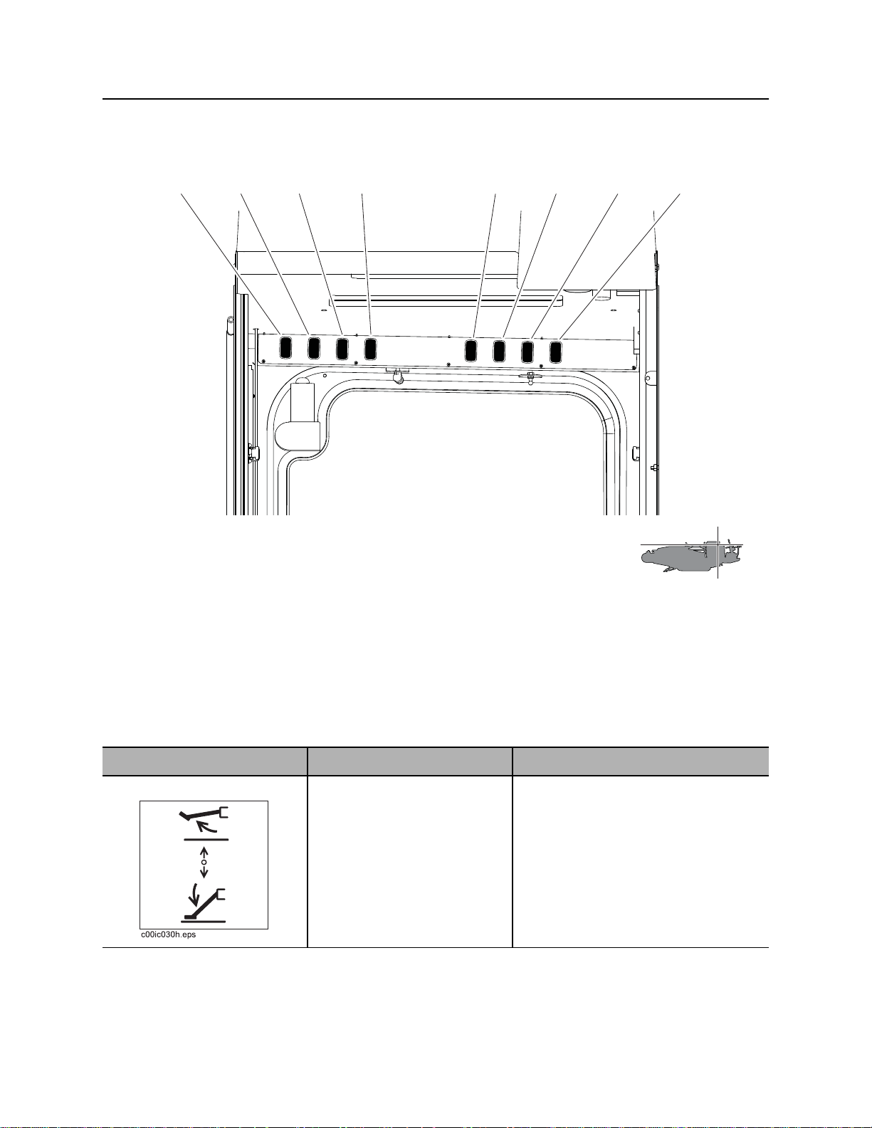
Cab Controls
EMERGENCY EXIT: Push rear window out to exit cab when door is blocked or inoperable.
Top/Rear
12
j29om002t.eps
1. Dome light switch
2. Air conditioner on/off switch
3. Air conditioner temperature dial
Item Description Notes
1. Dome light switch To turn on or off, press.
2. AC on/off switch To turn air conditioner on,
press left.
To turn air conditioner off,
press right.
3
4. Air conditioner fan speed dial
5. Air conditioner filter
45
Page 48

Controls - 48 JT60/JT60 All Terrain Operator’s Manual
Cab Controls
Item Description Notes
3. AC temperature dial To adjust air temperature,
turn dial.
4. AC fan speed dial To adjust fan speed, turn dial.
5. Air conditioner filter Filters air coming into cab. Clean or replace air filter as needed.
Page 49

JT60/JT60 All Terrain Operator’s Manual Controls - 49
Override Box
Override Box
1
AB
4
j40om073w.eps
1. Tracker control key
2. Drilling fluid flow override switch
3. Rotation or right track override switch
Item Description Notes
1. Tracker control key To allow tracker operator to
stop thrust and rotation, move
key to enable position (up).
To override tracker control
mode, move key to disable
position (right).
4. Thrust/pullback or left track override switch
5. Drill override port
6. Drive override port
IMPORTANT: Remove key and keep
in tracker operator’s possession.
See “Tracker Control” on page 133.
2
3
2. Drilling fluid flow
override switch
To turn fluid on, move right.
To turn fluid off, move left.
Connect to drill connector (B) to
control fluid flow.
Page 50

Controls - 50 JT60/JT60 All Terrain Operator’s Manual
Override Box
Item Description Notes
3. Thrust/pullback or left
track override switch
4. Rotation or right track
override switch
5. Drill override port Connect tether to this port to
For thrust or to move track
forward, move up.
For pullback or to move track
backward, move down.
For counterclockwise rotation
or to move track forward,
move up.
For clockwise rotation or to
move track backward, move
down.
override drill functions.
Connect to drill connector (B) to
control thrust/pullback.
Connect to drive connector (A) to
control left track.
IMPORTANT: When connected to
connector (A), drill fluid switch
functions as an operator presence
switch.
Connect to drill connector (B) to
control rotation.
Connect to drive connector (A) to
control right track.
IMPORTANT: When connected to
connector (A), drill fluid switch
functions as an operator presence
switch.
6. Drive override port Connect tether to this port to
override drive functions.
Page 51

JT60/JT60 All Terrain Operator’s Manual Controls - 51
Battery
Battery
1
j40om019w.eps
Item Description Notes
1. Battery disconnect
switch
To disconnect, turn switch
counterclockwise.
To connect, turn switch
clockwise.
IMPORTANT: Use when servicing
unit and during long-term storage.
Page 52

Controls - 52 JT60/JT60 All Terrain Operator’s Manual
Engine Compartment
Engine Compartment
2
3
1
4
j40om009w.eps
1. Manual throttle switch
2. Drill mode switch (optional)
Item Description Notes
1. Manual throttle switch To throttle up, press top of
switch.
To throttle down, press
bottom of switch.
3. Fan speed switch
4. Inner rotation hour meter (optional)
IMPORTANT: Switch only functions if
CAN communication is not operable.
Page 53

JT60/JT60 All Terrain Operator’s Manual Controls - 53
Engine Compartment
Item Description Notes
2. Drill mode switch To select AT Rock mode,
press top.
To select AT Dirt mode, move
to middle.
To select JT mode, press
bottom.
3. Fan speed switch For high speed, press top.
For automatic speed, press
bottom.
c00ic063w.eps
Use AT Rock mode when using AT
pipe with inner rod and rock drilling
bits.
Use AT Dirt mode when using AT
pipe with inner rod and adapter to use
dirt tool head.
Use JT drilling mode when using JT
pipe without inner rod.
IMPORTANT: See “Prepare Drilling
Unit” on page 80 for how to set up unit
for each drilling mode.
IMPORTANT: If switch is on high
speed, fan will run at full speed all the
time. If switch is on auto speed, fan
speed will vary in relation to engine
temperature.
4. Inner rotation hour
meter
Displays inner rotation
operating time.
Use these times to schedule service
for downhole tool and inner shaft. See
“Service” on page 167.
Page 54

Controls - 54 JT60/JT60 All Terrain Operator’s Manual
Rear Console
Rear Console
1
j40om010w.eps
1. Pressure wand on/off switch
Item Description Notes
1. Pressure wand on/off
switch
c00ic064w.eps
To turn pressure wand on,
press top.
To turn pressure wand off,
press bottom.
Page 55

JT60/JT60 All Terrain Operator’s Manual Operation Overview - 55
Operation Overview
Chapter Contents
Planning. . . . . . . . . . . . . . . . . . . . . . . . . . . . . . . . . . 56
Setting Up at Jobsite . . . . . . . . . . . . . . . . . . . . . . . 56
Drilling . . . . . . . . . . . . . . . . . . . . . . . . . . . . . . . . . . . 57
Backreaming . . . . . . . . . . . . . . . . . . . . . . . . . . . . . . 58
Leaving Jobsite. . . . . . . . . . . . . . . . . . . . . . . . . . . . 58
Storing Equipment . . . . . . . . . . . . . . . . . . . . . . . . . 58
Page 56

Operation Overview - 56 JT60/JT60 All Terrain Operator’s Manual
Planning
Planning
1. Gather information about jobsite. See page 61.
2. Inspect jobsite. See page 62.
3. Classify jobsite. See page 64.
4. Plan bore path. See page 67.
5. Select drilling mode based on jobsite conditions. See page 79.
6. Check supplies and prepare equipment. See page 77.
7. Load equipment. See page 89.
Setting Up at Jobsite
1. Prepare jobsite. See page 76.
2. Unload drilling unit from trailer. See page 91.
3. Assemble drill string. See page 99.
4. Position drilling unit and frame. See page 95.
5. Assemble strike system. See page 123.
6. Anchor drilling unit. See page 119.
7. Connect fluid system. See page 95.
8. Calibrate tracker with beacon that will be installed in beacon housing. See tracker operator’s manual.
Page 57

JT60/JT60 All Terrain Operator’s Manual Operation Overview - 57
Drilling
Drilling
1. Start system. See page 95.
2. Engage tracker control if desired. See page 133.
3. Drill first pipe. See page 102.
• JT mode
• AT dirt mode
• AT mode
4. Swab the hole to remove cuttings (AT mode only). See page 103.
5. Record bore path. See page 110.
6. Add pipe. See page 104.
7. Drill remaining pipes in pipe box.
• Correct direction. See page 106.
• Engage cruise control. See page 154.
8. Remove empty pipe box and add full box (see page 147) or add up to a single row of drill pipe to empty
box (see page 149) to complete bore.
9. Surface drill head. See page 110.
• Remove drill head.
• Grease downhole tool (AT mode).
Page 58

Operation Overview - 58 JT60/JT60 All Terrain Operator’s Manual
Backreaming
Backreaming
1. Assemble backream string. See page 99.
2. Start drilling unit and adjust throttle.
3. Set drilling fluid flow. Check that fluid flows through all nozzles. See page 136.
4. Remove pipe from bore. See page 114.
5. Remove full pipe box and add empty box (see page 147) or remove up to a single row of drill pipe from
full box (see page 149) to complete backream.
6. Remove pullback device. See page 116.
Backreaming Tips
• Plan backreaming job before drilling. Plan bore path as straight as possible. Check bend limits of
pullback material. Check that appropriate pullback devices are on hand.
• Keep all bends as gradual as possible.
• Drilling fluid quality is a key factor in backreaming success. Contact your Ditch Witch dealer for
information on testing water, selecting additives, and mixing drilling fluid.
• Backreaming requires more fluid than drilling. Make sure enough fluid is used.
Leaving Jobsite
1. Remove downhole tools.
2. Remove anchors. See page 121.
3. Rinse unit and downhole tools. See page 164.
4. Disassemble strike system and disconnect from fluid system. See page 124.
5. Stow tools. See page 165.
6. Load unit onto trailer. See page 89.
Storing Equipment
1. For cold weather storage, antifreeze drilling unit. See page 162.
2. For long-term storage, disconnect battery disconnect switch.
Page 59

JT60/JT60 All Terrain Operator’s Manual Prepare - 59
Prepare
Chapter Contents
Gather Information . . . . . . . . . . . . . . . . . . . . . . . . . 61
• Review Job Plan . . . . . . . . . . . . . . . . . . . . . . . . . . . . . . . . . . . . . . . . . . 61
• Notify One-Call Services. . . . . . . . . . . . . . . . . . . . . . . . . . . . . . . . . . . . 61
• Examine Pullback Material . . . . . . . . . . . . . . . . . . . . . . . . . . . . . . . . . . 61
• Arrange for Traffic Control. . . . . . . . . . . . . . . . . . . . . . . . . . . . . . . . . . . 61
• Plan for Emergency Services . . . . . . . . . . . . . . . . . . . . . . . . . . . . . . . . 61
Inspect Site . . . . . . . . . . . . . . . . . . . . . . . . . . . . . . . 62
• Identify Hazards . . . . . . . . . . . . . . . . . . . . . . . . . . . . . . . . . . . . . . . . . . 62
• Select Start and End Points . . . . . . . . . . . . . . . . . . . . . . . . . . . . . . . . . 63
Classify Jobsite. . . . . . . . . . . . . . . . . . . . . . . . . . . . 64
• Inspect Jobsite . . . . . . . . . . . . . . . . . . . . . . . . . . . . . . . . . . . . . . . . . . . 64
• Select a Classification. . . . . . . . . . . . . . . . . . . . . . . . . . . . . . . . . . . . . . 64
• Apply Precautions. . . . . . . . . . . . . . . . . . . . . . . . . . . . . . . . . . . . . . . . . 65
Plan Bore Path . . . . . . . . . . . . . . . . . . . . . . . . . . . . 67
• Recommended Bend Limits . . . . . . . . . . . . . . . . . . . . . . . . . . . . . . . . . 68
• Entry Pitch. . . . . . . . . . . . . . . . . . . . . . . . . . . . . . . . . . . . . . . . . . . . . . . 72
• Minimum Setback . . . . . . . . . . . . . . . . . . . . . . . . . . . . . . . . . . . . . . . . . 72
• Minimum Depth. . . . . . . . . . . . . . . . . . . . . . . . . . . . . . . . . . . . . . . . . . . 73
• Bore Path Calculator. . . . . . . . . . . . . . . . . . . . . . . . . . . . . . . . . . . . . . . 73
Page 60

Prepare - 60 JT60/JT60 All Terrain Operator’s Manual
Prepare Jobsite. . . . . . . . . . . . . . . . . . . . . . . . . . . . 76
• Mark Bore Path. . . . . . . . . . . . . . . . . . . . . . . . . . . . . . . . . . . . . . . . . . . 76
• Prepare Entry Point. . . . . . . . . . . . . . . . . . . . . . . . . . . . . . . . . . . . . . . . 76
Check Supplies and Prepare Equipment . . . . . . . 77
• Check Supplies. . . . . . . . . . . . . . . . . . . . . . . . . . . . . . . . . . . . . . . . . . . 77
• Prepare Equipment. . . . . . . . . . . . . . . . . . . . . . . . . . . . . . . . . . . . . . . . 78
• Select Drilling Mode . . . . . . . . . . . . . . . . . . . . . . . . . . . . . . . . . . . . . . . 79
• Prepare Drilling Unit . . . . . . . . . . . . . . . . . . . . . . . . . . . . . . . . . . . . . . . 80
• Assemble Accessories . . . . . . . . . . . . . . . . . . . . . . . . . . . . . . . . . . . . . 81
Page 61

JT60/JT60 All Terrain Operator’s Manual Prepare - 61
Gather Information
Gather Information
A successful job begins before the bore. The first step in planning is reviewing information already
available about the job and jobsite.
Review Job Plan
Review blueprints or other plans and make sure you have taken bore enlargement during backreaming
and pullback into account. Check for information about existing or planned structures, elevations, or
proposed work that may be taking place at the same time.
Notify One-Call Services
Contact your local One-Call (811 in USA) or the One-Call referral number (888-258-0808 in USA and
Canada) to have underground utilities located before digging. Also contact any utilities that do not
participate in the One-Call service.
Examine Pullback Material
Ask for a sample of the material you will be pulling back. Check its weight and stiffness. Contact the
manufacturer for bend radius information. Check that you have appropriate pullback devices.
Arrange for Traffic Control
If working near a road or other traffic area, contact local authorities about safety procedures and
regulations.
Plan for Emergency Services
Have the telephone numbers for local emergency and medical facilities on hand. Check that you will have
access to a telephone.
Page 62

Prepare - 62 JT60/JT60 All Terrain Operator’s Manual
Inspect Site
Inspect Site
Inspect jobsite before transporting equipment. Check for the following:
• overall grade or slope
• changes in elevation such as hills or open trenches
• obstacles such as buildings, railroad crossings, or streams
• signs of utilities (See “Inspect Jobsite” on page 64.)
• traffic
• access
• soil type and condition
• water supply
• sources of locator interference (rebar, railroad tracks, etc.)
Take soil samples from several locations along bore path to determine best bit and backreamer
combinations.
Identify Hazards
Identify safety hazards and classify jobsite. See “Classify Jobsite” on page 64.
Jobsite hazards could cause death or serious injury. Use
correct equipment and work methods. Use and maintain proper safety
equipment.
To help avoid injury:
• Wear personal protective equipment including hard hat, safety eye wear, and hearing protection.
• Do not wear jewelry or loose clothing.
• Notify One-Call and companies which do not subscribe to One-Call.
• Comply with all utility notification regulations before digging or drilling.
• Verify location of previously marked underground hazards.
• Mark jobsite clearly and keep spectators away.
Remember, jobsite is classified by hazards in place -- not by line being installed.
Page 63

JT60/JT60 All Terrain Operator’s Manual Prepare - 63
Inspect Site
Select Start and End Points
Select one end to use as a starting point. Consider the following when selecting a starting point:
Slope
Always level machine before drilling. Fluid system should be parked on a level site. Consider how slope
will affect drilling unit setup, bending pipe, and fluid flow out of hole.
Traffic
Vehicle and pedestrian traffic must be a safe distance from drilling equipment. Allow at least 10’ (3 m)
buffer zone around equipment.
Space
Check that starting and ending points allow enough space for gradual pipe bending. See “Minimum
Setback” on page 72.
Check that there is enough space to work and to set up electric strike system.
Comfort
Consider shade, wind, fumes, and other site features.
Drill downhill when possible so fluid will flow away from drilling unit.
Page 64

Prepare - 64 JT60/JT60 All Terrain Operator’s Manual
Classify Jobsite
Classify Jobsite
Inspect Jobsite
• Follow U.S. Department of Labor regulations on excavating and trenching (Part 1926, Subpart P) and
other similar regulations.
• Contact your local One-Call (811 in USA) or the One-Call referral number (888-258-0808 in USA and
Canada) to have underground utilities located before digging. Also contact any utilities that do not
participate in the One-Call service.
• Inspect jobsite and perimeter for evidence of underground hazards, such as:
– “buried utility” notices
– utility facilities without overhead lines
– gas or water meters
– junction boxes
– drop boxes
– light poles
– manhole covers
– sunken ground
• Have an experienced locating equipment operator sweep area within 20’ (6 m) to each side of bore
path. Verify previously marked line and cable locations.
• Mark location of all buried utilities and obstructions.
• Classify jobsite.
Select a Classification
Jobsites are classified according to underground hazards present.
If working . . . then classify jobsite as . . .
within 10’ (3 m) of a buried electric line electric
within 10’ (3 m) of a natural gas line natural gas
in sand, granite, or concrete which is capable of producing
crystalline silica (quartz) dust
within 10’ (3 m) of any other hazard other
IMPORTANT: If you have any doubt about jobsite classification, or if jobsite might contain unmarked
hazards, take steps outlined previously to identify hazards and classify jobsite before working.
crystalline silica (quartz) dust
Page 65

JT60/JT60 All Terrain Operator’s Manual Prepare - 65
Classify Jobsite
Apply Precautions
Once classified, precautions appropriate for jobsite must be taken.
Electric Jobsite Precautions
Electric shock. Contacting electric lines will cause death or serious injury.
Know location of lines and stay away.
In addition to using a directional drilling system with an electric strike system, use one or both of these
methods.
• Expose line by careful hand digging or soft excavation. Use beacon to track bore path. Have someone
observe clearance between drill head and backreamer when crossing a line.
• Have service shut down while work is in progress. Have electric company test lines before returning
them to service.
Natural Gas Jobsite Precautions
Fire or explosion possible. Fumes could ignite and cause burns. No
smoking, no flame, no spark.
Explosion possible. Serious injury or equipment damage could occur.
Follow directions carefully.
In addition to using a directional drilling system and positioning equipment upwind from gas lines, use one
or both of these methods.
• Expose lines by careful hand digging or soft excavation. Use beacon to track bore path. Have
someone observe clearance between drill head and backreamer when crossing a line.
• Have gas shut off while work is in progress. Have gas company test lines before returning them to
service.
Page 66

Prepare - 66 JT60/JT60 All Terrain Operator’s Manual
Classify Jobsite
Crystalline Silica (Quartz) Dust Precautions
Jobsite hazards could cause death or serious injury. Use correct
equipment and work methods. Use and maintain proper safety equipment.
To help avoid injury:
• Use water spray or other means to control dust when cutting, drilling, or working materials such as
concrete, sand, or rock containing quartz. The dust may contain silica.
• Workers exposed to dust must wear appropriate breathing protection. Silica dust may cause lung
disease and is known to the State of California to cause cancer.
Follow OSHA or other guidelines for exposure to crystalline silica when trenching, sawing or drilling
through material that might produce dust containing crystalline silica (quartz).
Other Jobsite Precautions
You may need to use different methods to safely avoid other underground hazards. Talk with those
knowledgeable about hazards present at each site to determine which precautions should be taken or if
job should be attempted.
Page 67

JT60/JT60 All Terrain Operator’s Manual Prepare - 67
Plan Bore Path
Plan Bore Path
Plan the bore path, from entry to end, before drilling begins. The Ditch Witch Trac Management System
Plus is available for planning your bore path. See your Ditch Witch dealer for details.
If not using Trac Management System Plus, mark the bore path on the ground with spray paint or flags, or
record it on paper for operator reference.
For complicated bores, consult an engineer. Have the jobsite surveyed and bore path calculated. Be sure
the engineer knows minimum entry pitch, bend limits of drill pipe, bend and tension limits of pullback
material, pipe lengths, and location of all underground utilities.
For less complicated bores, plan the bore based on four measurements:
• recommended bend limit
• entry pitch
• minimum setback
• minimum depth
IMPORTANT: See the following pages for more information about these measurements. If not using
Trac Management System Plus, see “Bore Path Calculator” on page 73 and use these measurements to
help plan your bore.
Page 68

Prepare - 68 JT60/JT60 All Terrain Operator’s Manual
Plan Bore Path
Recommended Bend Limits
NOTICE: Only use approved JT60 Power Pipe HD, All Terrain Power Pipe, or Power Pipe Forged with
this drilling unit.
Ditch Witch drill pipes are designed to bend slightly during operation. Slight bending allows for steering and
correcting direction. Bending beyond recommended limits will cause damage that might not be visible. This
damage adds up and will later lead to sudden drill pipe failure.
IMPORTANT: Consider recommended bend limits during any bend, not just during bore entry.
Pipe Pitch
Ditch Witch drill pipe is tested to bend at a
maximum percent pitch. For JT60 or JT60 All
Terrain drill pipe, make sure pitch (A) changes no
more than 7% over the full length of each pipe.
NOTICE: Bending drill pipe more sharply than
recommended will damage pipe and cause
failure over time. Changes in pitch must be
equally distributed over the length of a pipe.
Maximum changes in pitch within 1-2’ (300-600
mm) of pipe create sharp bends that will damage
pipe.
Monitor the pitch of each pipe with the remote display on the operator’s console. (See tracking system
operation instructions.)
Bend Radius
JT60 All Terrain drill pipes have a tested minimum
bend radius of 205’ (63 m). This means that a 90degree bend in the bore path:
• has a radius (A) of 205’ (63 m)
• requires approximately 471’ (143.6 m) of drill
pipe (B).
NOTICE: Bending drill pipe more sharply than
recommended will damage the pipe and cause
failure over time.
• If bend radius is reduced, drill pipe life is
reduced.
• If bend radius is increased, drill pipe life
is increased.
Page 69

JT60/JT60 All Terrain Operator’s Manual Prepare - 69
Plan Bore Path
JT60 Power Pipe drill pipes have a tested minimum
bend radius of 170’ (57.8 m). This means that a 90degree bend in the bore path:
• has a radius (A) of 170’ (57.8 m)
• requires approximately 267’ (81.4 m) of drill pipe (B).
JT60 Power Pipe Forged drill pipes have a tested
minimum bend radius of 168.7’ (51.4 m). This means that
a 90-degree bend in the bore path:
• has a radius (A) of 168.7’ (51.4 m)
• requires approximately 265’ (80.8 m) of drill pipe (B).
NOTICE: Bending drill pipe more sharply than recommended will damage the pipe and cause failure
over time.
• If bend radius is reduced, drill pipe life is reduced.
• If bend radius is increased, drill pipe life is increased.
C
13
1
A
A
j40om065w.eps
24
B
B
IMPORTANT: Use the charts on the next page to keep bends within safe limits.
Page 70

Prepare - 70 JT60/JT60 All Terrain Operator’s Manual
Plan Bore Path
Pipe-By-Pipe Bend Limits - JT60 Power Pipe HD
Pipe
(C)
1 0’ 7.9” 14’ 11.8” 10 61’ 11.9” 131’ 3.4”
2 2’ 7.7” 29’ 10.1” 11 73’ 11.8” 140’ 3.4’
3 5’ 11.1” 44’ 5.7” 12 86’ 8.6” 148’ 2.4”
4 10’ 5.7” 58’ 9.1” 13 100’ 1.2” 154’ 11.6”
5 16’ 3.3” 72’ 7.1” 14 114’ 0.3” 160’ 6.3”
6 23’ 3.3” 85’ 10.3” 15 128’ 4.7” 164’ 10.0”
7 31’ 4.9” 98’ 5.4” 16 143’ 0.9” 167’ 10.3”
8 40’ 7.5” 110’ 3.4” 17 157’ 11.7” 169’ 6.9”
9 50’ 10.1” 121’ 3.0” 18 170’ 170’
Deflection (A) Forward (B) Pipe
(C)
Deflection (A) Forward (B)
Pipe-By-Pipe Bend Limits - JT60 Power Pipe Forged
Pipe
(C)
1 0’ 8.0” 14’ 11.8” 10 62’ 3.7” 131’ 0.8”
Deflection (A) Forward (B Pipe
(C)
Deflection (A) Forward (B)
2 2’ 7.9” 29’ 10.1” 11 74’ 4.2” 140’ 0.1”
3 5’ 11.5” 44’ 5.6” 12 87’ 1.6” 147’ 10.2”
4 10’ 6.5” 58’ 9.0” 13 100’ 6.7” 154’ 6.3”
5 16’ 4.4” 72’ 6.7” 14 114’ 6.3” 157’ 11.8”
6 23’ 4.8” 85’ 9.7” 15 128’ 11.1” 164’ 2.1”
7 31’ 7.0” 98’ 4.5” 16 143’ 7.6” 167’ 1.0”
8 40’ 10.1” 110’ 2.0” 17 158’ 6.5” 168’ 8.1”
9 51’ 1.4” 121’ 1.1” 18 169’ 169’
Page 71

JT60/JT60 All Terrain Operator’s Manual Prepare - 71
Plan Bore Path
Pipe-By-Pipe Bend Limits - JT60 Power Pipe All Terrain
Pipe
(C)
1 0’ 5.9” 14’ 3.0” 13 78’ 3.1” 161’ 1.5”
2 1’ 11.8” 28’ 5.1” 14 89’ 9.2” 169’ 6.6”
3 4’ 5.4” 42’ 5.6” 15 101’ 9.9” 177’ 1.8”
4 7’ 10.6” 56’ 3.7” 16 114’ 4.7” 183’ 10.7”
5 12’ 3.3” 69’ 10.5” 17 127’ 4.7” 189’ 8.9”
6 17’ 7.2” 83’ 1.2” 18 140’ 9.2” 194’ 8.1”
7 23’ 9.9” 95’ 11.1” 19 154’ 5.4” 198’ 8.0”
8 30’ 11.2” 108’ 3.4” 20 168’ 4.6” 201’ 8.4’
9 38’ 10.5” 120’ 1.4” 21 182’ 5.9” 203’ 9.1”
10 47’ 7.5” 131’ 4.5” 22 196’ 8.5” 204’ 10.0”
11 57’ 1.7” 141’ 11.9” 23 205’ 205’
12 67’ 4.4” 151’ 11.1”
Deflection (A) Forward (B) Pipe
(C)
Deflection (A) Forward (B)
Page 72

Prepare - 72 JT60/JT60 All Terrain Operator’s Manual
Plan Bore Path
Entry Pitch
Entry pitch is the slope of the drill frame compared with the slope of the ground. Determine entry pitch one
of two ways:
1. With Pitch Beacon
• Lay pitch beacon on the ground and read
pitch.
• Lay pitch beacon on drill frame and read pitch.
• Subtract ground pitch from drilling unit pitch.
2. With Measurements
• Measure from the ground to front end of drill
frame (H1).
• Measure from the ground to back end of frame
(H2).
• Subtract (H1) from (H2). Record this number.
• Measure the distance between front and back
points (C).
• Divide (H2-H1) by (C), then multiply by 100.
This is your pitch.
IMPORTANT: A shallow entry pitch (A1) allows you
to reach horizontal sooner and with less bending.
Increasing entry pitch (A2) makes minimum setback
longer and deeper.
Minimum Setback
Setback is the distance from the entry point to where
pipe becomes horizontal (B1).
NOTICE: If setback is too small (B2), you will
exceed bend limits and damage the pipe.
Page 73

JT60/JT60 All Terrain Operator’s Manual Prepare - 73
Plan Bore Path
Minimum Depth
Because you must bend pipe gradually, entry pitch and
bend limits determine how deep the pipe will be when
it becomes horizontal. This is called the minimum
depth.
• To reduce minimum depth (D1), reduce entry
pitch. This also decreases setback.
• To increase minimum depth (D2), increase
entry pitch. This also increases setback.
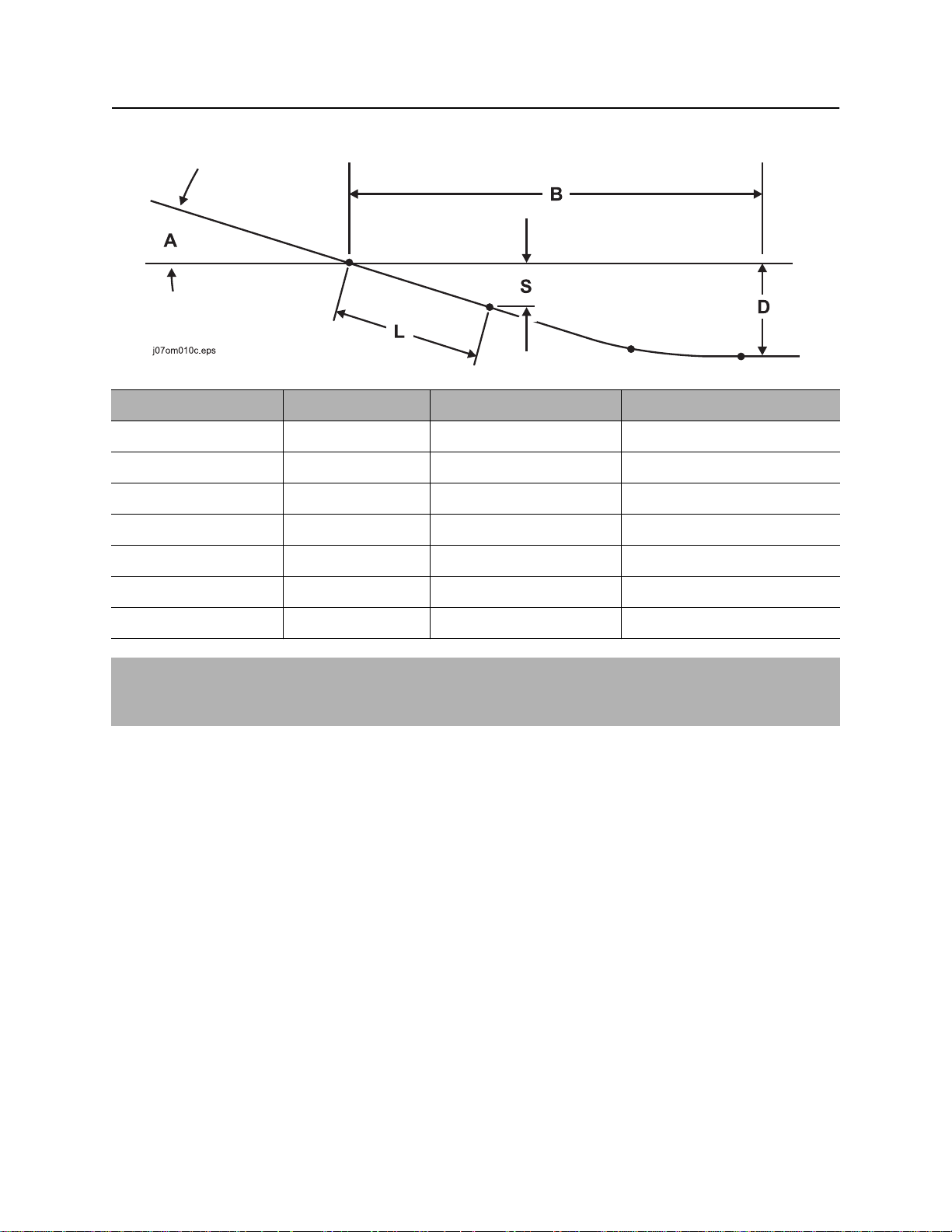
Bore Path Calculator
Entry pitch, setback, and minimum depth work together with bend limits to determine the bore path. To find
the setback (B) and entry pitch (A) that will take you to the desired minimum depth (D), use the chart
below.
JT60 Power Pipe HD
Minimum depth (D) Entry pitch (A) Setback (B) Depth to begin steering (S)
4’ 10” 18”/10.0° 42’ 2” 2’ 3”
5’ 7” 19%/11.0° 45’ 1” 2.6”
6’ 5” 21%/12.0° 47’ 11” 2’ 8”
7’ 3” 23%/13.0° 50’ 9” 2’ 11”
8’ 2” 25%/14.0° 53’ 7” 3’ 2”
9’ 2” 27%/15.0° 56’ 5” 3’ 4”
10’ 2” 29%/16.0° 59’ 3” 3’ 7”
IMPORTANT: Numbers in table based on 170’ (51.8 m) minimum bend radius, beacon housing, EZ-
Connect, connector, transition sub, and 1/3 of first drill pipe (L, totaling 12’ 10” [3.9 m]) in the ground
before steering.
Page 74
Prepare - 74 JT60/JT60 All Terrain Operator’s Manual
Plan Bore Path
JT60 Power Pipe Forged
Minimum depth (D) Entry pitch (A) Setback (B) Depth to begin steering (S)
4’ 10” 18”/10.0° 41’ 12” 2’ 3”
5’ 7” 19%/11.0° 44’ 10” 2’ 6”
6’ 5” 21%/12.0° 47’ 9” 2’ 8”
7’ 3” 23%/13.0° 50’ 6” 2’ 11”
8’ 2” 25%/14.0° 53’ 4” 3’ 2”
9’ 1” 27%/15.0° 56’ 2” 3’ 4”
10’ 1” 29%/16.0° 58’ 11” 3’ 7”
IMPORTANT: Numbers in table based on 168.7’ (51.4 m) minimum bend radius, beacon housing, EZ-
Connect, connector, transition sub, and 1/3 of first drill pipe (L, totaling 12’ 10” [3.9 m]) in the ground
before steering.
Page 75
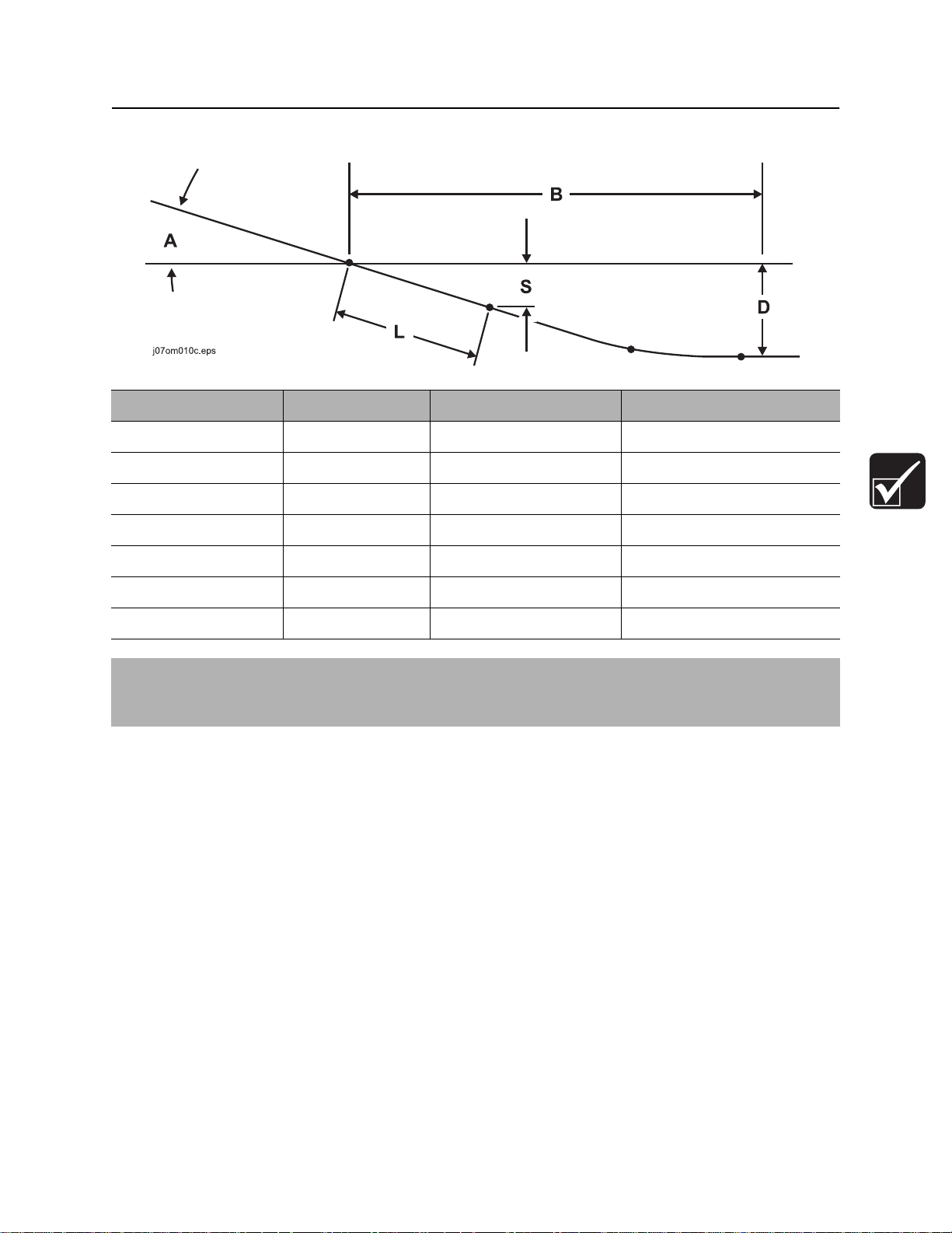
JT60/JT60 All Terrain Operator’s Manual Prepare - 75
Plan Bore Path
JT60 Power Pipe AT
Minimum depth (D) Entry pitch (A) Setback (B) Depth to begin steering (S)
5’ 4” 18”/10.0° 47’ 12” 2’ 3”
6’ 2” 19%/11.0° 51’ 6” 2’ 5”
7’ 2” 21%/12.0° 54’ 11” 2’ 8”
8’1” 23%/13.0° 58’ 5” 2’ 10”
9’ 2” 25%/14.0° 61’ 10” 3’ 1”
10’ 3” 27%/15.0° 65’ 3” 3’ 4”
11’ 5” 29%/16.0° 68’ 7” 3’ 6”
IMPORTANT: Numbers in table based on 168.7’ (51.4 m) minimum bend radius, beacon housing, EZ-
Connect, connector, transition sub, and 1/3 of first drill pipe (L, totaling 12’ 10” [3.9 m]) in the ground
before steering.
Page 76

Prepare - 76 JT60/JT60 All Terrain Operator’s Manual
Prepare Jobsite
Prepare Jobsite
Jobsite hazards could cause death or serious injury. Use
correct equipment and work methods. Use and maintain proper safety
equipment.
To help prevent injury:
• Classify jobsite as electric if jobsite classification is in question or if the possibility of unmarked
electric utilities exists.
• Cutting high voltage cable can cause electrocution. Expose lines by hand before digging.
Mark Bore Path
Mark your planned bore path and all located utility lines with flags or paint.
Prepare Entry Point
For bore to be successful, first pipe must be straight
as it enters the ground.
To help ensure that the first pipe does not bend, dig
a small starting hole so that the first pipe is drilled
into a vertical surface.
To prevent bending or straining pipe, position
drilling unit for straight entry.
Page 77

JT60/JT60 All Terrain Operator’s Manual Prepare - 77
Check Supplies and Prepare Equipment
Check Supplies and Prepare Equipment
Check Supplies
• receiver/transmitter or tracker with spare batteries
• beacons with new and spare batteries
• two-way radios with new and spare batteries
• hydraulic wrench (see “Hydratong Wrenches” on page 141)
• transition sub
• anchoring equipment and accessories
• bits, screens, nozzles (see “Downhole Tools” on page 136)
• adapters, pipe, beacon housings
• marking flags or paint
• water and additional hoses
• fuel
• drilling fluid additives (see “Drilling Fluid” on page 128)
• spare fuses
• keys
• backreamers, swivels, pulling devices (see “Backreamers” on page 138)
• wash down hose and spray gun
• duct tape
• spray lubricant
• tool joint compound (see “Recommended Lubricants/Service Key” on page 170)
• electrically insulating boots and gloves. Boots must have high tops and meet the electric hazard
protection requirements of ASTM F2413 when tested at 14,000 volts. Tuck legs of pants completely
inside boots.
• personal protective equipment, such as hard hat and safety glasses
• notepad and pencil
Page 78

Prepare - 78 JT60/JT60 All Terrain Operator’s Manual
Check Supplies and Prepare Equipment
Prepare Equipment
Fluid Levels
• fuel
• hydraulic fluid
• engine coolant
• battery charge
• engine oil
Condition and Function
• filters (air, oil, hydraulic)
• fluid pump
• couplers
• tires and tracks
• pumps and motors
• drilling fluid mixer
• hoses and valves
• water tanks
Page 79

JT60/JT60 All Terrain Operator’s Manual Prepare - 79
Check Supplies and Prepare Equipment
Select Drilling Mode
Three drilling setups are available with this unit:
• AT rock mode
• AT dirt mode
• JT mode
Select the best setup based on jobsite conditions.
Mode Situation used Downhole tools Capabilities
AT
Rock
AT
dirt
JT Soft or intermittent soft rock or other
Once drilling mode has been selected, configure drilling unit to match mode.
Rock, soft rock, other non-compressible
soils. Any other situation with difficult
steering because of hard soil
conditions.
When one bore out of several can be
better or more quickly done with
conventional downhole tools. This bore
is such that changing to JT pipe is not
practical.
compressible soils.
• All Terrain drill pipe
• Rockmaster tool
• All Terrain drill pipe
• beacon housing
• transition sub
• standard JT tools
• JT drill pipe
• standard JT tools
• 60,000 lb (266 kN)
of thrust
• dither
• inner rotation
• 60,000 lb (266 kN)
of thrust
• dither
• no inner rotation
• 60,000 lb (266 kN)
of thrust
• no dither
• no inner rotation
Page 80

Prepare - 80 JT60/JT60 All Terrain Operator’s Manual
Check Supplies and Prepare Equipment
Prepare Drilling Unit
AT Rock Mode
• Verify unit has not been converted to JT mode. Ensure All Terrain SaverLok, shuttle stops, pipe gripper
pads, pipe guide blocks, pipe wiper, shuttle stop, wrench jaw blocks, and pipe lifter pads are installed.
• Inspect Rockmaster tool and select bit based on jobsite conditions.
• Use drill bit type anchors.
• Load All Terrain pipe and pipe box onto unit.
• Move mode selector switch to AT Rock position.
AT Dirt Mode
• Verify unit has not been converted to JT mode. Ensure All Terrain SaverLok, shuttle stops, pipe gripper
pads, pipe guide blocks, pipe wiper, shuttle stop, wrench jaw blocks, and pipe lifter pads are installed.
• Use transition sub between All Terrain pipe and beacon housing. Select soil bit based on jobsite
conditions.
• Use auger type anchors if in soft soil conditions.
• Load All Terrain pipe and pipe box onto unit.
• Move mode selector switch to AT DIRT position.
Page 81

JT60/JT60 All Terrain Operator’s Manual Prepare - 81
Check Supplies and Prepare Equipment
JT Mode
IMPORTANT: Use conversion kit (p/n 101-136) and refer to installation instructions (p/n 051-329).
• Install SaverLok, pipe gripper pads, pipe guide blocks, pipe wiper, shuttle stop, wrench jaw blocks, and
pipe lifter pads sized to handle Mach 1 pipe.
• Use standard transition sub and beacon housing. Select soil bit based on jobsite conditions.
• Use auger type anchors.
• Load JT pipe and pipe box onto unit.
NOTICE: Do not put JT pipe into a large All Terrain pipe box. Pipe can jam and box can be
damaged. Use JT pipe box.
• Move mode selector switch to JT position.
Assemble Accessories
Fire Extinguisher
If required, mount a fire extinguisher near the power unit but away from possible points of ignition. The fire
extinguisher should always be classified for both oil and electric fires. It should meet legal and regulatory
requirements.
Page 82

Prepare - 82 JT60/JT60 All Terrain Operator’s Manual
Check Supplies and Prepare Equipment
Page 83

JT60/JT60 All Terrain Operator’s Manual Drive - 83
Drive
Chapter Contents
Start Unit . . . . . . . . . . . . . . . . . . . . . . . . . . . . . . . . . 84
Steer Unit . . . . . . . . . . . . . . . . . . . . . . . . . . . . . . . . 84
Shut Down Unit . . . . . . . . . . . . . . . . . . . . . . . . . . . 86
Page 84

Drive - 84 JT60/JT60 All Terrain Operator’s Manual
Start Unit
Start Unit
1. Insert key.
2. Turn ignition switch to the run position (key on, engine off). Engine preheat indicator (on engine
display) will light.
3. Wait for engine preheat indicator to go off before starting.
4. Run engine at low throttle for 5 minutes.
Steer Unit
IMPORTANT: Survey field of vision before operating the machine and position all mirrors provided to
ensure that visibility is not restricted.
To steer drilling unit, follow instructions for type of steering desired.
To steer while moving forward, push forward and then move to left or right.
Drilling unit will gradually turn to left or right.
To steer while moving backward, pull back and then move to left or right.
Drilling unit will gradually turn to left or right.
For tight steering in low speed, move control to center position and then to a
corner. Tracks will counter-rotate and turn drilling unit in a tight circle.
c00ic145h.eps
Page 85

JT60/JT60 All Terrain Operator’s Manual Drive - 85
Steer Unit
Safe Slope Operation
Tipover possible. Machine can tip over and crush you.
To help avoid injury:
• Always operate with heavy end uphill.
• Drive cautiously at all times.
• Never jerk control levers. Use a steady even motion.
• Do not park unit on slope without lowering anchor frame to the ground, returning all controls to
neutral position, shutting down unit, and applying parking brake.
Operating safely on a slope depends upon many factors including:
• Distribution of machine weight, including front loading and absence of load
• Height of load
• Even or rough ground conditions
• Potential for ground giving way causing unplanned tilt forward, reverse or sideways
• Nearness of ditches, ruts, stumps or other obstructions and sudden changes in slope
• Speed
• Turning
• Braking performance
• Operator skill
These varying factors make it impractical to specify a maximum safe operating angle in this manual. It is
therefore important for the operator to be aware of these conditions and adjust operation accordingly.
Maximum engine angle and braking performance are two absolute limits which must never be exceeded.
These maximums are stated below since they are design limits. These design limits usually exceed the
operating limits and must never be used alone to establish safe operating angle for variable conditions.
Maximum engine lubrication angle – 43°
Maximum service brake retarding force – equal to traction of both tracks.
Maximum secondary brake retarding force – equal to traction of one track.
Maximum park brake holding force – equal to traction of both tracks.
Page 86

Drive - 86 JT60/JT60 All Terrain Operator’s Manual
Shut Down Unit
Shut Down Unit
1. Stop track movement.
2. Engage parking brake.
3. Run engine at low throttle for 3 minutes to cool.
4. Turn ignition switch to STOP.
5. Remove key.
Page 87

JT60/JT60 All Terrain Operator’s Manual Transport - 87
Transport
Chapter Contents
Lift . . . . . . . . . . . . . . . . . . . . . . . . . . . . . . . . . . . . . . 88
Haul . . . . . . . . . . . . . . . . . . . . . . . . . . . . . . . . . . . . . 89
• Load . . . . . . . . . . . . . . . . . . . . . . . . . . . . . . . . . . . . . . . . . . . . . . . . . . . 89
• Tie Down . . . . . . . . . . . . . . . . . . . . . . . . . . . . . . . . . . . . . . . . . . . . . . . 90
• Unload . . . . . . . . . . . . . . . . . . . . . . . . . . . . . . . . . . . . . . . . . . . . . . . . . 91
Tow . . . . . . . . . . . . . . . . . . . . . . . . . . . . . . . . . . . . . 91
Page 88

Transport - 88 JT60/JT60 All Terrain Operator’s Manual
Lift
Lift
This machine is not configured for lifting. If the machine must be lifted, load machine into a container or
onto a platform appropriate for lifting. See “Specifications” for weight of machine.
Pipe Box Lifting Procedure
Crushing weight could cause death or serious injury. Use
proper procedures and equipment or stay away.
Pipe box lifting points are identified by lifting decals. Lifting at other points is
unsafe and can damage equipment.
Ensure that proper remove/install procedure is followed. See “Remove/
Install Pipe Box” on page 147.
Use crane capable of supporting the equipment's
size and weight. See “Specifications” on page 207
or measure and weigh equipment before lifting.
IMPORTANT: Lift only one box of pipe at a
time.
Page 89

JT60/JT60 All Terrain Operator’s Manual Transport - 89
Haul
Haul
Load
Crushing weight. If load falls or moves it could kill or crush you. Use
proper procedures and equipment or stay away.
To help avoid injury:
• Load and unload trailer on level ground.
• Verify that trailer wheels are blocked.
• Attach trailer to vehicle before loading or unloading.
• Place ten to fifteen percent of total vehicle weight (equipment plus trailer) on tongue to help prevent
trailer sway.
1. Fasten and adjust seat belt.
2. Start drilling unit engine.
3. Move drilling unit to rear of trailer and align with ramps or center of trailer bed.
4. Slow engine to low throttle and slowly drive unit onto trailer.
5. Lower stabilizers to trailer floor.
6. Lower drill frame to trailer floor.
7. Stop engine when unit is safely positioned on trailer bed.
8. Attach tiedowns to drilling unit where tiedown decals are located.
Page 90
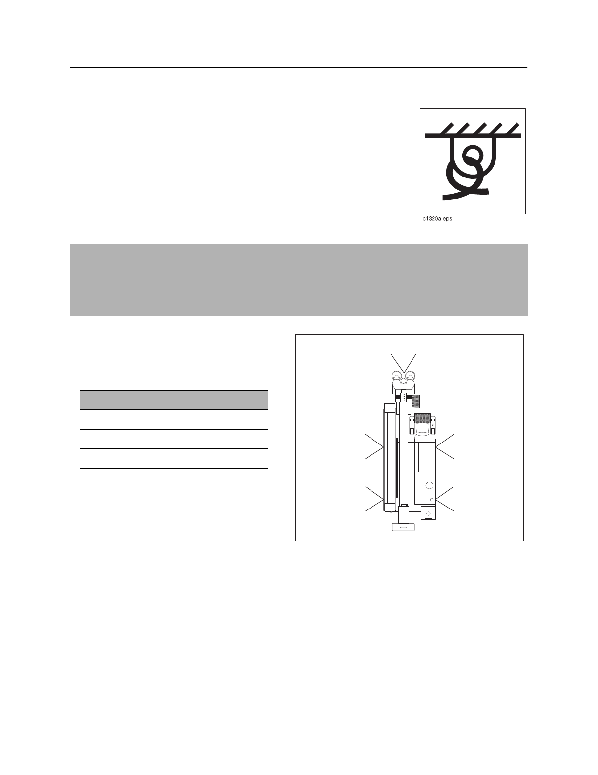
Transport - 90 JT60/JT60 All Terrain Operator’s Manual
C
Haul
Tie Down
Points
Tiedown points are identified by tiedown decals. Securing to trailer at other
points is unsafe and can damage machinery.
Procedure
NOTICE:
• Wrenches can open after engine shutdown. Ensure that any pipe in wrenches is attached to spindle
and downhole tools are removed from the pipe before transport.
• Use Grade 7-3/8” (18.7 cm) transport chain to secure drilling unit.
Loop a transport chain around each tie down
point. See chart below for correct distances
between tiedown ends. Make sure tiedowns are
tight before transporting.
Distance Measurement
A greater than 18”
B less than 50”
C greater than 10”
j40om068w.eps
B
C
A
A
AA
Page 91

JT60/JT60 All Terrain Operator’s Manual Transport - 91
Tow
Unload
Crushing weight. If load falls or moves it could kill or crush you. Use
proper procedures and equipment or stay away.
To help avoid injury:
• Load and unload trailer on level ground.
• Ensure trailer wheels are blocked.
• Attach trailer to vehicle before loading or unloading.
1. Lower trailer or ramps.
2. Fasten and adjust seat belt.
3. Remove tiedowns.
4. Start drilling unit engine.
5. Raise stabilizers.
6. Raise drill frame.
7. Slow engine to low throttle and slowly back unit down trailer or ramps.
Tow
Under normal conditions, drilling unit should not be towed. If unit breaks down and towing is necessary:
• tow for short distances at less than 1 mph (1.6 km/h),
• attach chains to indicated tow points facing towing vehicle,
• use maximum towing force of 1.5 times unit weight,
• disengage track planetaries.
Page 92

Transport - 92 JT60/JT60 All Terrain Operator’s Manual
Tow
To disengage track planetaries, reverse small cover plate in center of planetary on each track drive.
IMPORTANT: When planetaries are disengaged, unit has no brakes.
A. Normal operation B. Towing
To attach chains to tow points, determine which points are facing towing vehicle.
If back tow points are facing towing vehicle, choose option A or B.
Option A: Loop chain through both tow points and attach to common cross member. Always pull straight
back.
Option B: Loop chain through each tow point and attach chains to towing vehicle. Always pull straight
back.
If front tow points are facing towing vehicle, loop chain through tow point and pull straight forward.
Page 93

JT60/JT60 All Terrain Operator’s Manual Conduct a Bore - 93
Conduct a Bore
Chapter Contents
Position Equipment . . . . . . . . . . . . . . . . . . . . . . . . 95
Connect Fluid System . . . . . . . . . . . . . . . . . . . . . . 95
Start System . . . . . . . . . . . . . . . . . . . . . . . . . . . . . . 95
Prime Drilling Fluid Pump . . . . . . . . . . . . . . . . . . . 96
Operate Carriage Control . . . . . . . . . . . . . . . . . . . 97
Clamp Pipe . . . . . . . . . . . . . . . . . . . . . . . . . . . . . . . 98
Assemble Drill String . . . . . . . . . . . . . . . . . . . . . . . 99
• Prepare Beacon Housing . . . . . . . . . . . . . . . . . . . . . . . . . . . . . . . . . . . 99
• Attach Transition Sub . . . . . . . . . . . . . . . . . . . . . . . . . . . . . . . . . . . . . 100
• Attach Beacon Housing . . . . . . . . . . . . . . . . . . . . . . . . . . . . . . . . . . . 100
• Connect Drill Pipe . . . . . . . . . . . . . . . . . . . . . . . . . . . . . . . . . . . . . . . 101
Drill First Pipe . . . . . . . . . . . . . . . . . . . . . . . . . . . . 102
• JT Mode/AT Dirt Mode . . . . . . . . . . . . . . . . . . . . . . . . . . . . . . . . . . . . 102
• AT Mode . . . . . . . . . . . . . . . . . . . . . . . . . . . . . . . . . . . . . . . . . . . . . . . 102
Swab the Hole . . . . . . . . . . . . . . . . . . . . . . . . . . . 103
Enable Automated Pipeloader System . . . . . . . 103
Page 94

Conduct a Bore - 94 JT60/JT60 All Terrain Operator’s Manual
Add Pipe . . . . . . . . . . . . . . . . . . . . . . . . . . . . . . . . 104
Correct Direction . . . . . . . . . . . . . . . . . . . . . . . . . 106
• Basic Rules . . . . . . . . . . . . . . . . . . . . . . . . . . . . . . . . . . . . . . . . . . . . 106
• Procedure . . . . . . . . . . . . . . . . . . . . . . . . . . . . . . . . . . . . . . . . . . . . . . 107
• Drill Head Position . . . . . . . . . . . . . . . . . . . . . . . . . . . . . . . . . . . . . . . 107
Record Bore Path . . . . . . . . . . . . . . . . . . . . . . . . . 110
Surface Drill Head . . . . . . . . . . . . . . . . . . . . . . . . 110
Assemble Backream String . . . . . . . . . . . . . . . . 112
Remove Pipe . . . . . . . . . . . . . . . . . . . . . . . . . . . . 114
Remove Pullback Device . . . . . . . . . . . . . . . . . . . 116
Page 95
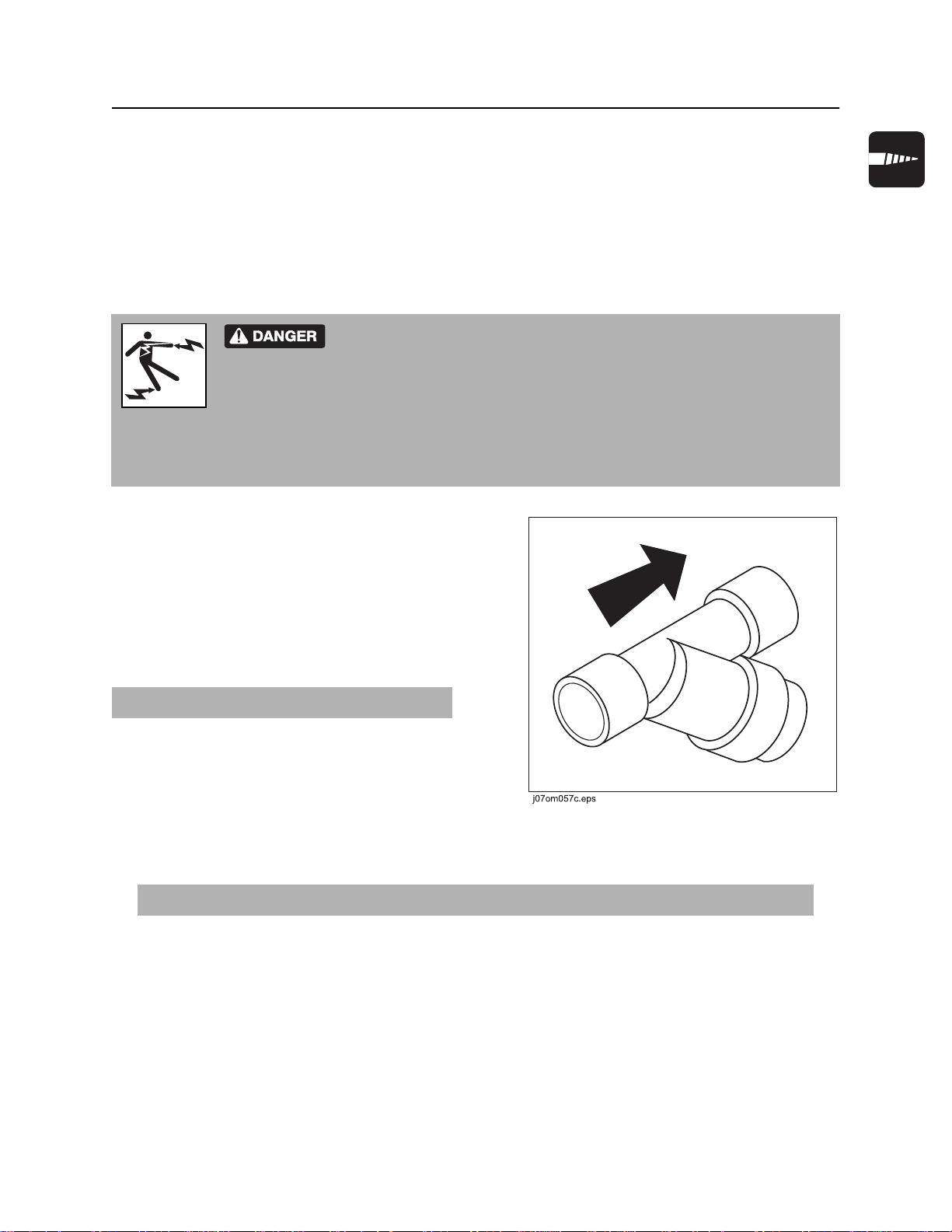
JT60/JT60 All Terrain Operator’s Manual Conduct a Bore - 95
Position Equipment
Position Equipment
1. Review bore plan and select drilling unit position and fluid unit position.
2. Move equipment into selected positions.
Connect Fluid System
Electric shock. Contacting electric lines will cause death or serious injury.
Know location of lines and stay away.
To help avoid injury, do not connect drilling unit to a public or private (business or home) water supply.
If an electrical strike occurs while drilling unit is connected to a fluid system, the fluid system will also
become electrified.
1. Connect fluid hose from mixing system to
drilling fluid pump. A 3” (76 mm) or larger,
non-collapsible hose is required.
2. Install y-strainer between mixing unit and
drilling fluid pump. Position strainer so that
drilling fluid flows in the direction of the arrow.
In most cases, positioning strainer at outlet of
mixing unit gives best results.
IMPORTANT: Clean y-strainer regularly.
Start System
1. Start drilling unit and remote fluid unit. Allow both engines to warm up.
IMPORTANT: Ensure that mixture of drilling fluid matches drilling conditions.
2. Enable tracker control mode if desired. See “Tracker Control” on page 133.
3. Press top of drilling unit throttle switch until engine is at full throttle.
4. Press and hold quick fill fluid pump switch until pipe fills and fluid pressure begins to rise.
Page 96

Conduct a Bore - 96 JT60/JT60 All Terrain Operator’s Manual
Prime Drilling Fluid Pump
Prime Drilling Fluid Pump
Incorrect procedures could result in death, injury, or property damage.
Learn to use equipment correctly.
To help avoid injury, prime the drilling fluid pump before use. Failure to prime the drilling fluid pump will
cause flow fluctuations, which will make it difficult to control the wash wand.
Pressurized fluid or air could pierce skin and cause injury
or death. Stay away.
Prime drilling fluid pump each time the tank is changed. To prime the pump:
1. Fill drilling fluid hose and connect hose to unit.
2. Operate mixing/transfer pump at full speed for 1 - 3 minutes to discharge air from system.
3. Return mixing/transfer pump to normal operating speed and continue the bore.
4. If drilling fluid pressure surges are observed, repeat step 2.
Page 97

JT60/JT60 All Terrain Operator’s Manual Conduct a Bore - 97
Operate Carriage Control
Operate Carriage Control
The thrust/rotation control has eight zones that allow four basic functions
(forward, backward, clockwise, counterclockwise) to be combined. The chart
below summarizes functions that occur when control is put at a combined
position. Operator must be in seat for control to function.
Carriage Movement Rotation Direction
forward clockwise
backward counterclockwise
Page 98

Conduct a Bore - 98 JT60/JT60 All Terrain Operator’s Manual
Clamp Pipe
Clamp Pipe
Turning shaft can kill you or crush arm or leg. Stay away.
To help avoid injury, clamp pipe only where shown. Clamping anywhere else on the pipe
will weaken the pipe. Pipe can later break, even when operating under normal loads.
Clamp on pipe when joint is centered between
wrenches (1 and 2). Always clamp on the larger
diameter areas on either side of the tool joint
face.
j40om066w.eps
Page 99
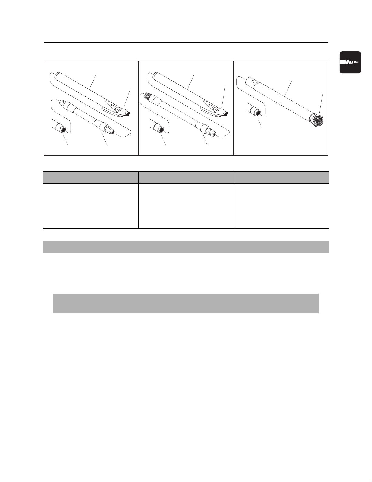
JT60/JT60 All Terrain Operator’s Manual Conduct a Bore - 99
Assemble Drill String
Assemble Drill String
1
2
1
2
3
4
j07om046c.eps
JT mode AT Dirt mode AT Rock mode
1. beacon housing
2. bit
3. transition sub
4. JT60 drill pipe
3
1. beacon housing
2. bit
3. transition sub
4. JT60 All Terrain drill pipe
4
3
1. Rockmaster tool
2. bit
3. JT60 All Terrain drill pipe
1
2
IMPORTANT: If no part number is listed, contact your Ditch Witch dealer about available options.
Prepare Beacon Housing
1. Select nozzles (JT and AT Dirt modes only) and bit.
IMPORTANT: A variety of nozzles and bits are available to suit your particular job conditions.
See “Downhole Tools” on page 136 for more information, or contact your Ditch Witch dealer.
2. Insert nozzle into beacon housing (JT and AT Dirt modes only).
3. Attach bit to beacon housing.
4. Install beacon, following beacon instructions for:
• battery replacement
• beacon positioning
5. Install beacon housing lid. See “Beacon Housings” on page 137.
6. Follow beacon instructions to check beacon operation.
7. Follow tracker instructions to calibrate beacon.
Page 100

Conduct a Bore - 100 JT60/JT60 All Terrain Operator’s Manual
Assemble Drill String
Attach Transition Sub
Use either machine torque or Hydratong wrenches to attach transition sub.
Machine Torque
1. Pull transition sub into front wrench.
2. Close wrench.
3. Lube joints.
4. Slowly make up joint.
5. Use full machine torque to tighten joint fully.
Hydratong
1. Lube joints with TJC.
2. Attach Hydratong to the joint in the join position and tighten joint. See “Hydratong Wrenches” on
page 141.
Attach Beacon Housing
1. Attach downhole tool to transition sub and hand tighten.
2. Attach Hydratong to the joint in the join position and tighten joint. See “Hydratong Wrenches” on
page 141.
 Loading...