


JT30/JT30 All Terrain
Tier 3 and Tier 4i
Operator’s
Manual
CMW
®
Issue 1.0
Original Instruction
053-2544

JT30 /JT30 All Terrain Operator’s Manual Overview - 2
Overview
Chapter Contents
Serial Number Location . . . . . . . . . . . . . . . . . . . . . . 3
Intended Use . . . . . . . . . . . . . . . . . . . . . . . . . . . . . . . 4
Equipment Modification . . . . . . . . . . . . . . . . . . . . . . 4
Unit Components . . . . . . . . . . . . . . . . . . . . . . . . . . . 5
Operator Orientation. . . . . . . . . . . . . . . . . . . . . . . . . 6
About This Manual . . . . . . . . . . . . . . . . . . . . . . . . . . 6
• Bulleted Lists. . . . . . . . . . . . . . . . . . . . . . . . . . . . . . . . . . . . . . . . . . . . . . 6
• Numbered Lists. . . . . . . . . . . . . . . . . . . . . . . . . . . . . . . . . . . . . . . . . . . . 6
• “Continued” Indicators. . . . . . . . . . . . . . . . . . . . . . . . . . . . . . . . . . . . . . . 6
CMW
Overview - 3 JT30 /JT30 All Terrain Operator’s Manual
Serial Number Location
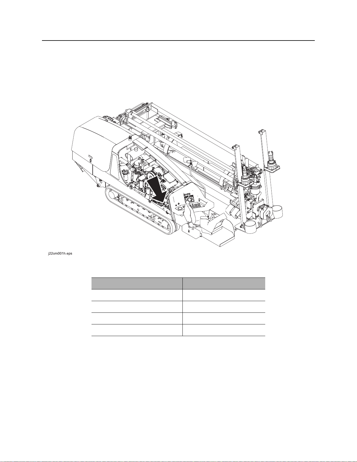
Serial Number Location
Record serial numbers and date of purchase in spaces provided. Drilling unit serial number is located as
shown.
CMW
Item
date of manufacture
date of purchase
drilling unit serial number
engine serial number

JT30 /JT30 All Terrain Operator’s Manual Overview - 4
Intended Use
Intended Use
The JT30 is a self-contained horizontal directional drilling unit designed to install buried cable and pipe to
distances of 650’ (200 m) depending on soil conditions. Its All Terrain version is designed to drill through
rock, cobblestone, broken rock, gravel, and caliche.
The unit is designed for operation in temperatures typically experienced in earth moving and construction
work environments. Provisions may be required to operate in extreme temperatures. Contact your Ditch
Witch dealer.
The JT30/JT30 All Terrain should be used with genuine Ditch Witch drilling fluid units and Ditch Witch
tracking equipment. It should be operated, serviced, and repaired only by persons familiar with its
particular characteristics and acquainted with the relevant safety procedures.
Use in any other way is considered contrary to the intended use.
Equipment Modification
This equipment was designed and built in accordance with applicable standards and regulations.
Modification of equipment could mean that it will no longer meet regulations and may not function properly
or in accordance with the operating instructions. Modification of equipment should only be made by
competent personnel possessing knowledge of applicable standards, regulations, equipment design
functionality/requirements and any required specialized testing.
CMW
Overview - 5 JT30 /JT30 All Terrain Operator’s Manual
Unit Components
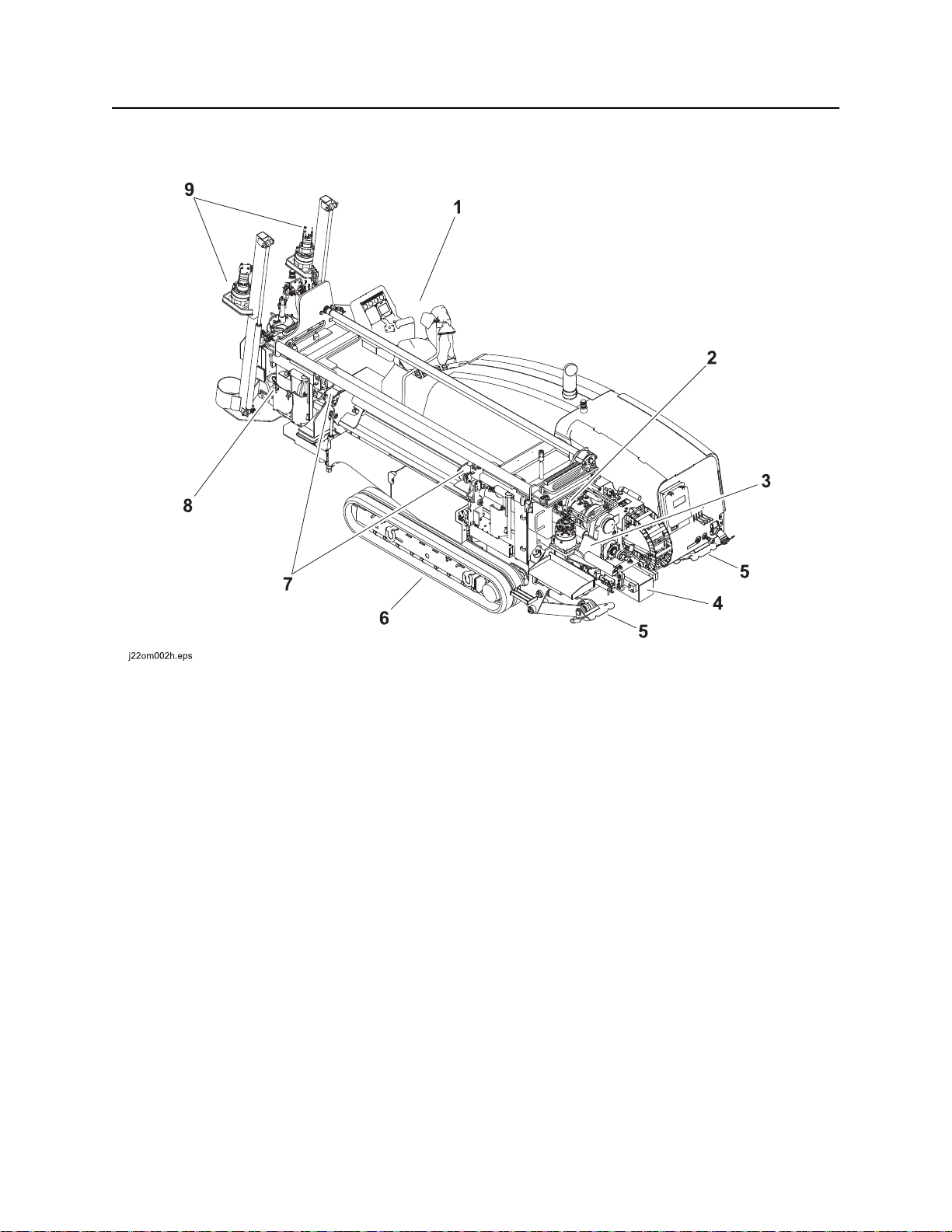
Unit Components
1. Operator’s station
2. Spindle
3. Carriage
4. Drill frame
5. Stabilizer
6. Tracks
7. Pipeloader
8. Vise wrenches
9. Anchoring system
CMW
JT30 /JT30 All Terrain Operator’s Manual Overview - 6
Operator Orientation
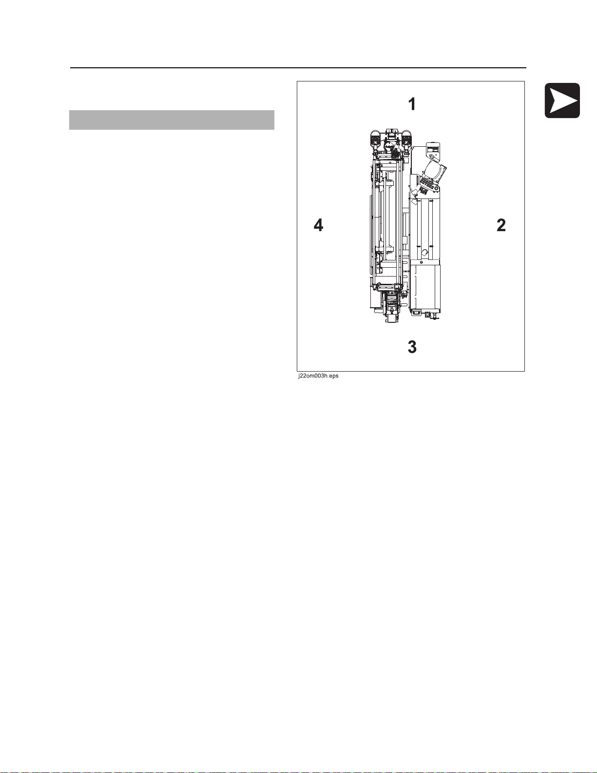
Operator Orientation
IMPORTANT: Top view of unit is shown.
1. Front of unit
2. Right side of unit
3. Rear of unit
4. Left side of unit
About This Manual
This manual contains information for the proper use of this machine. See the beige Operation Overview
pages for basic operating procedures. Cross references such as “See page 50” will direct you to detailed
procedures.
Bulleted Lists
Bulleted lists provide helpful or important information or contain procedures that do not have to be
performed in a specific order.
Numbered Lists
Numbered lists contain illustration callouts or list steps that must be performed in order.
CMW

Overview - 7 JT30 /JT30 All Terrain Operator’s Manual
CMW

JT30 /JT30 All Terrain Operator’s Manual Foreword - 8
Foreword
This manual is an important part of your equipment. It provides safety information and operation
instructions to help you use and maintain your Ditch Witch equipment.
Read this manual before using your equipment. Keep it with the equipment at all times for future reference.
If you sell your equipment, be sure to give this manual to the new owner.
If you need a replacement copy, contact your Ditch Witch dealer. If you need assistance in locating a
dealer, visit our website at www.ditchwitch.com or write to the following address:
The Charles Machine Works, Inc.
Attn: Marketing Department
PO Box 66
Perry, OK 73077-0066
USA
The descriptions and specifications in this manual are subject to change without notice. The Charles
Machine Works, Inc. reserves the right to improve equipment. Some product improvements may have
taken place after this manual was published. For the latest information on Ditch Witch equipment, see your
Ditch Witch dealer.
Thank you for buying and using Ditch Witch equipment.
CMW

Foreword - 9 JT30 /JT30 All Terrain Operator’s Manual
JT30/JT30 All Terrain
Tier 3 and Tier 4i
Operator’s Manual
Issue number 1.0/OM-07/12
Part number 053-2544
Copyright 2012
by The Charles Machine Works, Inc.
, Ditch Witch, CMW, Jet Trac, Subsite, Fluid Miser, Power Pipe, and The
Underground Authority are registered trademarks of The Charles Machine Works, Inc.
This product is covered by one or more of the following patents:
U.S. 5490569; 5684466; 5713423; 5794719; 5880680; 5941322; 6085852; 6109371; 6179065; 6250403; 6250404; 6311790;
6411094; 6543551; 6550547; 6672409; 6739413; 6761231; 6776246; 6808210; 6827158; 6848506; 6871712; 7011166; 7038454;
7759824; 7025152; 7347283; 7413031; 7392858; 7600584; 7628226; 7987924; RE37,450; RE37,975; RE38,418; AU 689,533;
706,544; 718,034; 755,862; CA 2,156,398; 2,217,899; DE 694 17 019; 695 29 634; 697 28 716; 69829107.7-08, 19712641;
66942993.5; EP 0683845; FR 674093; GB 2312006; 817901; 146608; EP 927892; EP674,093; EP846,841; UK 0984132; JP
3,458,247; other U.S. and foreign patents pending.
CMW
JT30 /JT30 All Terrain Operator’s Manual Contents - 10
Contents
Overview
machine serial number, information about the type of work this machine is designed
to perform, basic machine components, and how to use this manual
Foreword
part number, revision level, and publication date of this manual, and factory contact
information
Safety
machine safety alerts and emergency procedures
Controls
machine controls, gauges, and indicators and how to use them
Operation Overview
an overview for completing a job with this machine: planning, setting up, installing
product, and restoring the jobsite; with cross references to detailed procedures
Prepare
procedures for inspecting and classifying the jobsite, planning the installation path,
and preparing the jobsite for work
Drive
procedures for startup, cold start, driving, and shutdown
2
8
12
22
64
68
88
Transport
procedures for lifting, hauling, and towing
Conduct a Bore
procedures for drilling and backreaming
Systems and Equipment
downhole tools and drill pipe, anchor, electric strike, tracker control, fluid systems,
and diagnostic codes
Complete the Job
procedures for restoring the jobsite and rinsing and storing equipment
Service
service intervals and instructions for this machine including lubrication, replacement
of wear items, and basic maintenance
92
100
128
190
196
CMW

Contents - 11 JT30 /JT30 All Terrain Operator’s Manual
Specifications
machine specifications including weights, measurements, power ratings, and fluid
capacities
Support
the warranty policy for this machine, and procedures for obtaining warranty
consideration and training
Service Record
a record of major service performed on the machine
234
240
244
CMW

JT30/JT30 All Terrain Operator’s Manual Safety - 12
Safety
Chapter Contents
Guidelines . . . . . . . . . . . . . . . . . . . . . . . . . . . . . . . . 13
Safety Alert Classifications . . . . . . . . . . . . . . . . . . 14
Safety Alerts . . . . . . . . . . . . . . . . . . . . . . . . . . . . . . 15
Emergency Procedures . . . . . . . . . . . . . . . . . . . . . 18
• Electric Strike Description. . . . . . . . . . . . . . . . . . . . . . . . . . . . . . . . . . . 18
• If an Electric Line is Damaged . . . . . . . . . . . . . . . . . . . . . . . . . . . . . . . 19
• If a Gas Line is Damaged . . . . . . . . . . . . . . . . . . . . . . . . . . . . . . . . . . . 20
• If a Fiber Optic Cable is Damaged . . . . . . . . . . . . . . . . . . . . . . . . . . . . 21
• If Machine Catches on Fire. . . . . . . . . . . . . . . . . . . . . . . . . . . . . . . . . . 21
CMW

Safety - 13 JT30/JT30 All Terrain Operator’s Manual
Guidelines
Guidelines
Follow these guidelines before operating any jobsite equipment:
• Complete proper training and read operator’s manual before using equipment.
• Contact your local One-Call (811 in USA) or the One-Call referral number (888-258-0808 in USA and
Canada) to have underground utilities located before digging. Also contact any utilities that do not
participate in the One-Call service.
• Classify jobsite based on its hazards and use correct tools and machinery, safety equipment, and work
methods for jobsite.
• Mark jobsite clearly and keep spectators away.
• Wear personal protective equipment.
• Review jobsite hazards, safety and emergency procedures, and individual responsibilities with all
personnel before work begins. Safety videos are available from your Ditch Witch dealer.
• Replace missing or damaged safety shields and safety signs.
• Use equipment carefully. Stop operation and investigate anything that does not look or feel right.
• Do not operate unit where flammable gas may be present.
• Contact your Ditch Witch dealer if you have any question about operation, maintenance, or equipment
use.
CMW

JT30/JT30 All Terrain Operator’s Manual Safety - 14
Safety Alert Classifications
Safety Alert Classifications
These classifications and the icons defined on the following pages work together to alert you to situations
which could be harmful to you, jobsite bystanders or your equipment. When you see these words and
icons in the book or on the machine, carefully read and follow all instructions. YOUR SAFETY IS AT
STAKE.
Watch for the three safety alert levels: DANGER, WARNING and CAUTION. Learn what each level
means.
indicates a hazardous situation that, if not avoided, will result in death or serious injury.
This signal word is to be limited to the most extreme situations.
indicates a hazardous situation that, if not avoided, could result in death or serious injury.
indicates a hazardous situation that, if not avoided, could result in minor or moderate
injury.
Watch for two other words: NOTICE and IMPORTANT.
NOTICE indicates information considered important, but not hazard-related (e.g., messages relating to
property damage).
IMPORTANT can help you do a better job or make your job easier in some way.
CMW
Safety - 15 JT30/JT30 All Terrain Operator’s Manual
Safety Alerts
Safety Alerts
Turning shaft will kill you or crush arm or leg. Stay away.
Electric shock. Contacting electric lines will cause death or serious injury.
Know location of lines and stay away.
Moving tools will kill or injure. Shut off drill string power when anyone can be
struck by moving or thrown tools. Never use pipe wrenches on drill string.
correct equipment and work methods. Use and maintain proper safety
equipment.
proper procedures and equipment or stay away.
Explosion possible. Serious injury or equipment damage could occur.
Follow directions carefully.
Jobsite hazards could cause death or serious injury. Use
Crushing weight could cause death or serious injury. Use
Moving parts could cut off hand or foot. Stay away.
CMW
Incorrect procedures could result in death, injury, or property damage.
Learn to use equipment correctly.
JT30/JT30 All Terrain Operator’s Manual Safety - 16
Safety Alerts
Improper control function could cause death or serious injury. If control does
not work as described in instructions, stop machine and have it serviced.
Looking into fiber optic cable could result in permanent vision damage. Do
not look into ends of fiber optic or unidentified cable.
Pressurized fluid or air could pierce skin and cause injury or
death. Stay away.
Fire or explosion possible. Fumes could ignite and cause burns. No
smoking, no flame, no spark.
Moving traffic - hazardous situation. Death or serious injury could result.
Avoid moving vehicles, wear high visibility clothing, post appropriate warning signs.
CMW
Safety - 17 JT30/JT30 All Terrain Operator’s Manual
Safety Alerts
Hot pressurized cooling system fluid could cause serious burns. Allow to
cool before servicing.
Flying objects may cause injury. Wear hard hat and safety glasses.
Hot parts may cause burns. Do not touch until cool.
Exposure to high noise levels may cause hearing loss. Wear hearing
protection.
Fall possible. Slips or trips may result in injury. Keep area clean.
Battery acid may cause burns. Avoid contact.
Improper handling or use of chemicals may result in illness, injury, or
equipment damage. Follow instructions on labels and in material safety data sheets
(MSDS).
Breathing crystalline silica dust may cause lung disease. Cutting, drilling, or
working materials such as concrete, sand, or rock containing quartz may result in exposure
to silica dust. Use dust control methods or appropriate breathing protection when exposed
to silica dust.
CMW
JT30/JT30 All Terrain Operator’s Manual Safety - 18
Emergency Procedures
Emergency Procedures
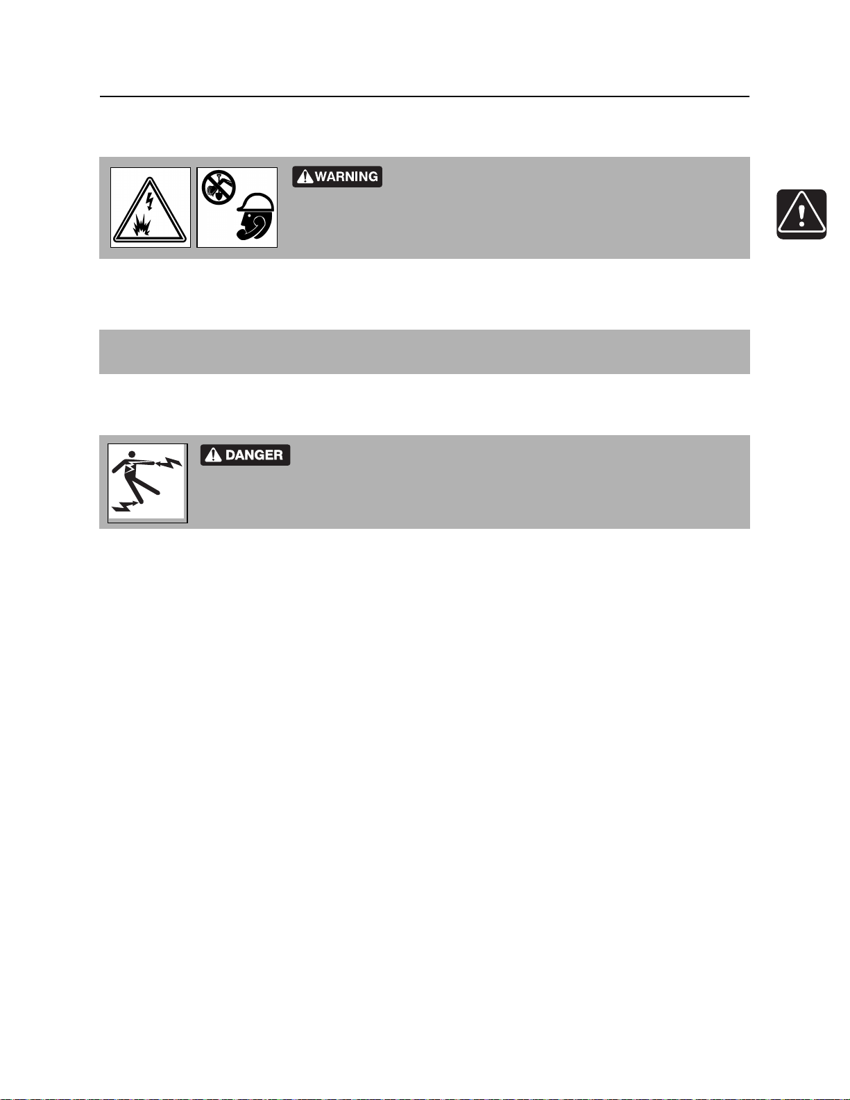
Jobsite hazards could cause death or serious injury. Use
correct equipment and work methods. Use and maintain proper safety
equipment.
Before operating any equipment, review emergency procedures and check that all safety precautions have
been taken.
EMERGENCY SHUTDOWN - Turn ignition switch to stop position or push remote engine stop button (if
equipped).
Electric Strike Description
Electric shock. Contacting electric lines will cause death or serious injury.
Know location of lines and stay away.
When working near electric cables, remember the following:
• Electricity follows all paths to ground, not just path of least resistance.
• Pipes, hoses, and cables will conduct electricity back to all equipment.
• Low voltage current can injure or kill. Many work-related electrocutions result from contact with less
than 440 volts.
Most electric strikes are not noticeable, but indications of a strike include:
• power outage
• smoke
• explosion
• popping noises
• arcing electricity
If any of these occur, or if strike alarm sounds or flashes, assume an electric strike has occurred.
CMW

Safety - 19 JT30/JT30 All Terrain Operator’s Manual
Emergency Procedures
If an Electric Line is Damaged
If you suspect an electric line has been damaged and you are on drilling unit or bonded equipment, DO
NOT MOVE. Remain on drilling machine and take the following actions. The order and degree of action will
depend on the situation.
• Warn people nearby that an electric strike has occurred.
• Have someone contact electric company.
• Reverse drilling direction and try to break contact. Do not touch drill pipe with hands or hand-held
tools.
• Press electric strike system status button.
• If alarm sounds again, stay where you are and wait for electric company to shut off power.
• If alarm does not sound and there is no other indication of a strike, wait at least one full minute
before moving away from equipment. Utility might use automatic reclosers which will restart
current flow. If alarm sounds again while waiting, stay where you are until electric company shuts
off power.
• If alarm does not sound but all lights in strike indicator are on, assume strike is continuing and stay
where you are until electric company shuts off power.
• Do not resume drilling or allow anyone into area until given permission by electric company.
If you suspect an electric line has been damaged and you are off drilling unit or bonded equipment, DO
NOT TOUCH ANY EQUIPMENT connected to drilling unit. Take the following actions. The order and
degree of action will depend on the situation.
• Stay where you are unless you are wearing electric insulating boots. If you leave, do not return to area
or allow anyone into area until given permission by electric company.
CMW
JT30/JT30 All Terrain Operator’s Manual Safety - 20
Emergency Procedures
If a Gas Line is Damaged
Fire or explosion possible. Fumes could ignite and cause burns. No
smoking, no flame, no spark.
Explosion possible. Serious injury or equipment damage could occur.
Follow directions carefully.
If you suspect a gas line has been damaged, take the following actions. The order and degree of action will
depend on the situation.
• Immediately shut off engine(s), if this can be done safely and quickly.
• Remove any ignition source(s), if this can be done safely and quickly.
• Warn others that a gas line has been cut and that they should leave the area.
• Leave jobsite as quickly as possible.
• Immediately call your local emergency phone number and utility company.
• If jobsite is along street, stop traffic from driving near jobsite.
• Do not return to jobsite until given permission by emergency personnel and utility company.
CMW

Safety - 21 JT30/JT30 All Terrain Operator’s Manual
Emergency Procedures
If a Fiber Optic Cable is Damaged
Do not look into cut ends of fiber optic or unidentified cable. Vision damage can occur.
If Machine Catches on Fire
Perform emergency shutdown procedure and then take the following actions. The order and degree of
action will depend on the situation.
• Immediately move battery disconnect switch (if equipped and accessible) to disconnect position.
• If fire is small and fire extinguisher is available, attempt to extinguish fire.
• If fire cannot be extinguished, leave area as quickly as possible and contact emergency personnel.
CMW

JT30 /JT30 All Terrain Operator’s Manual Controls - 22
Controls
Chapter Contents
Set-Up Console . . . . . . . . . . . . . . . . . . . . . . . . . . . 23
Tethered Ground Drive Controller . . . . . . . . . . . . 27
Left Control Console . . . . . . . . . . . . . . . . . . . . . . . 29
• Engine Display . . . . . . . . . . . . . . . . . . . . . . . . . . . . . . . . . . . . . . . . . . . 29
• Pipeloading controls . . . . . . . . . . . . . . . . . . . . . . . . . . . . . . . . . . . . . . . 33
• Drilling/Operation controls . . . . . . . . . . . . . . . . . . . . . . . . . . . . . . . . . . 36
Right Control Console . . . . . . . . . . . . . . . . . . . . . . 40
• Controls . . . . . . . . . . . . . . . . . . . . . . . . . . . . . . . . . . . . . . . . . . . . . . . . 40
• Indicators . . . . . . . . . . . . . . . . . . . . . . . . . . . . . . . . . . . . . . . . . . . . . . . 43
• Gauges . . . . . . . . . . . . . . . . . . . . . . . . . . . . . . . . . . . . . . . . . . . . . . . . . 47
Information Center . . . . . . . . . . . . . . . . . . . . . . . . . 49
• Displays. . . . . . . . . . . . . . . . . . . . . . . . . . . . . . . . . . . . . . . . . . . . . . . . . 49
• Soft keys . . . . . . . . . . . . . . . . . . . . . . . . . . . . . . . . . . . . . . . . . . . . . . . . 51
Anchoring System Console. . . . . . . . . . . . . . . . . . 53
Seat/Armrest . . . . . . . . . . . . . . . . . . . . . . . . . . . . . . 55
Cab Controls (Optional) . . . . . . . . . . . . . . . . . . . . . 57
Engine Compartment Controls . . . . . . . . . . . . . . . 60
CMW
Controls - 23 JT30 /JT30 All Terrain Operator’s Manual
Set-Up Console
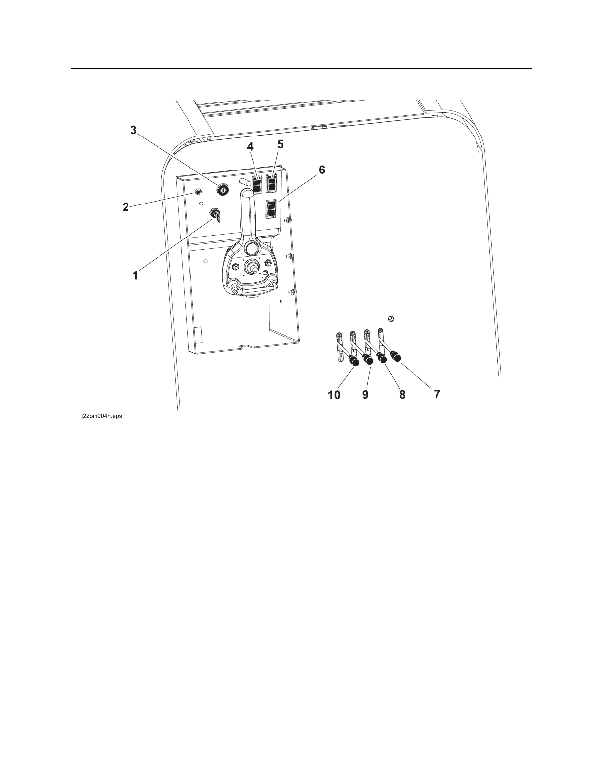
Set-Up Console
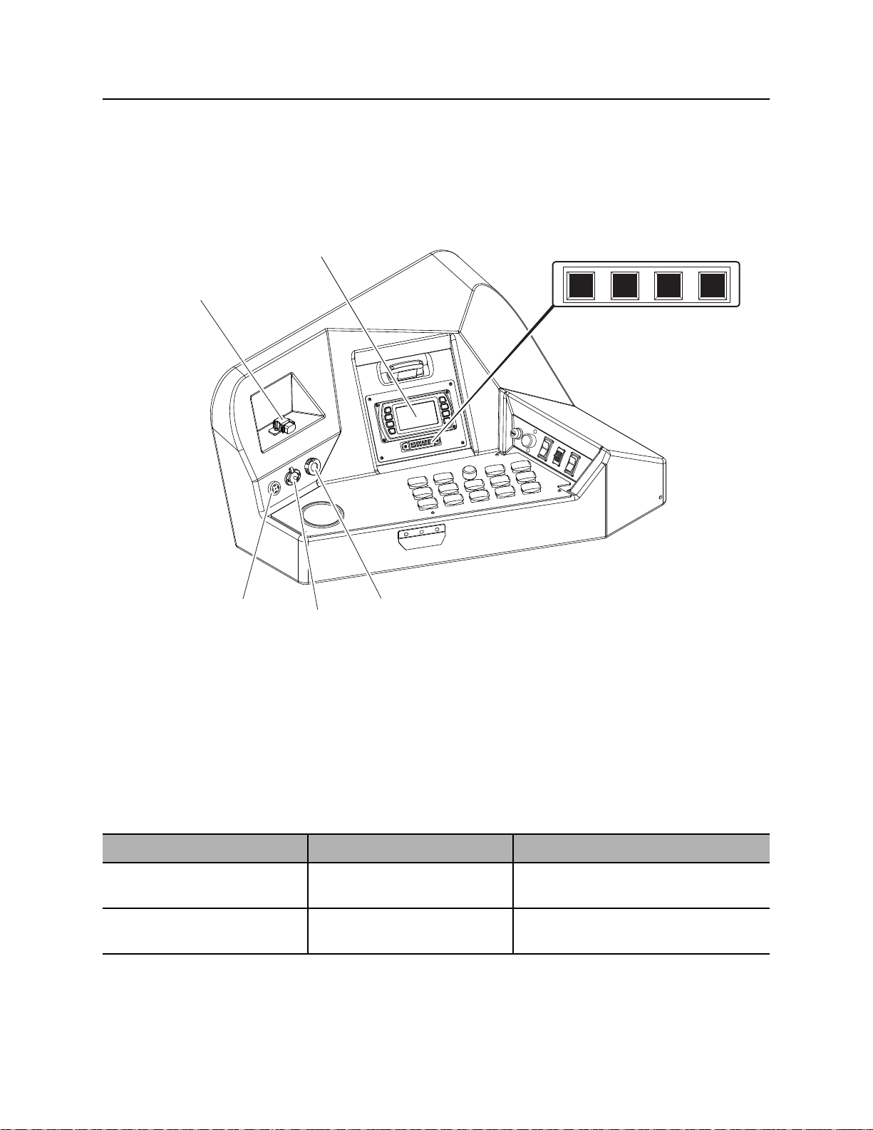
1. Tracker control key
2. Cold start wait indicator
3. Ignition switch
4. Left track switch
5. Right track switch
CMW
6. Engine shutdown override switch
7. Right stabilizer control
8. Left stabilizer control
9. Back frame tilt control
10. Front frame tilt control
JT30 /JT30 All Terrain Operator’s Manual Controls - 24
Set-Up Console
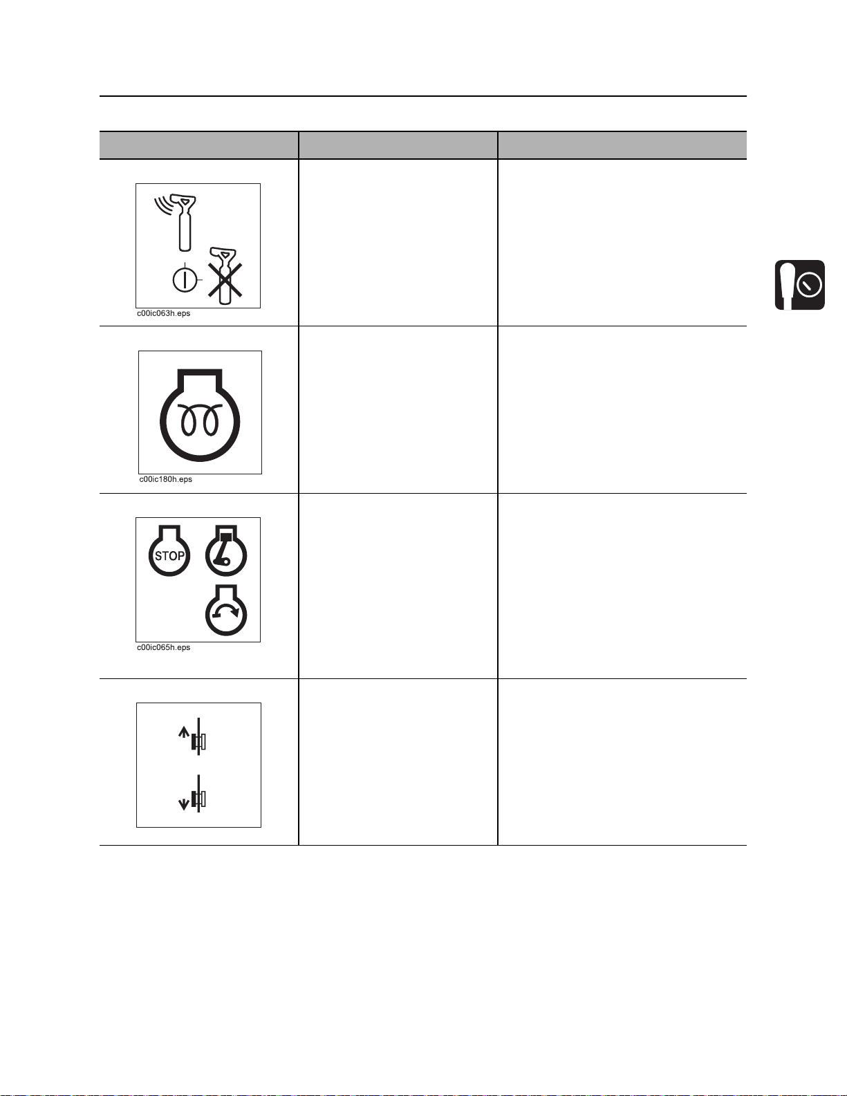
Item Description Notes
1. Tracker control key To allow tracker operator to
stop thrust and rotation, move
key to enable position (up).
To override tracker control
mode, move key to disable
position (right).
2. Cold start wait indicator Lights when intake air preheater is operating.
Wait until light goes off before
starting engine.
3. Ignition switch To start engine, insert key and
turn clockwise.
To stop engine, turn key
counterclockwise.
IMPORTANT: Remove key and keep
in tracker operator’s possession.
IMPORTANT:
• Restart engine with ignition switch
after it has been turned off with
tethered control remote engine
stop switch.
4. Left track switch To move forward, press top.
To move backward, press
bottom.
c00ic147h.eps
• If wrenches are engaged when
engine is stopped with ignition
switch, wrenches will release and
then engage when unit is started.
IMPORTANT: Use track switches only
if tethered control is inoperable.
CMW
Controls - 25 JT30 /JT30 All Terrain Operator’s Manual
Set-Up Console
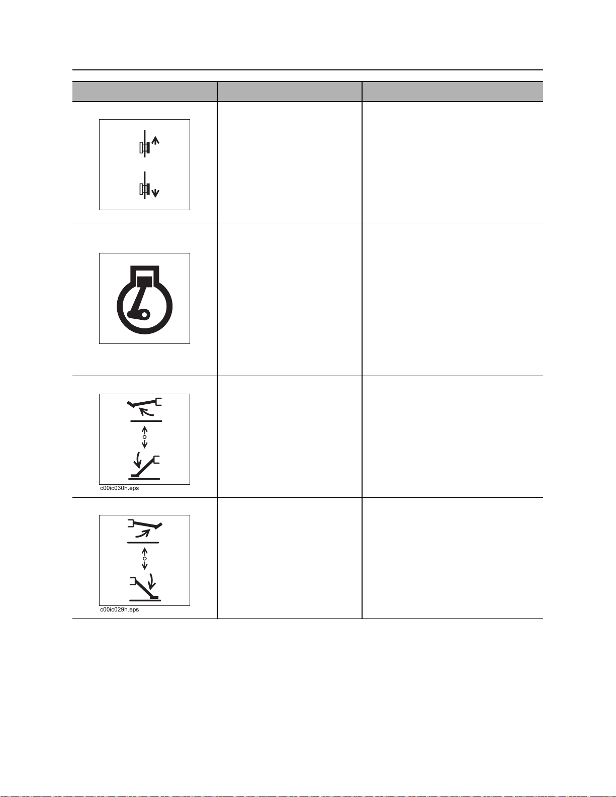
Item Description Notes
5. Right track switch To move forward, press top.
To move backward, press
bottom.
c00ic148h.eps
6. Engine shutdown
override switch
If engine shutdown indicator
comes on, turn ignition switch
to STOP and press to delay
engine shutdown for 30
seconds.
c00ic178h.eps
7. Left stabilizer control To raise, pull up.
To lower, push down.
IMPORTANT: Use track switches only
if tethered control is inoperable.
This control allows a temporary
override of engine shutdown.
NOTICE: After 30 seconds, engine
will again shut down unless fault
condition has been cleared on
diagnostic gauge.
IMPORTANT: See “Electronic
Controlled Engine Overview” on
page 169 for more information on Tier
3 engines.
IMPORTANT: Lower left and right
stabilizers to the ground together,
then adjust individually.
8. Right stabilizer control To raise, pull up.
To lower, push down.
WARNING: Crushing weight could
cause death or serious injury. Use
proper procedures and equipment or
stay away.
IMPORTANT: Lower left and right
stabilizers to the ground to stabilize
unit and then adjust for side-to-side
stability.
WARNING: Crushing weight could
cause death or serious injury. Use
proper procedures and equipment or
stay away.
CMW
JT30 /JT30 All Terrain Operator’s Manual Controls - 26
Set-Up Console
Item Description Notes
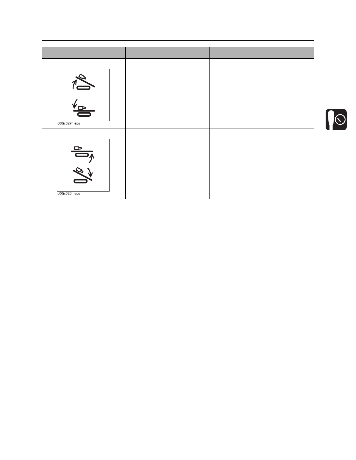
9. Back frame tilt control To raise, pull up.
To lower, push down.
10. Front frame tilt control To raise, pull up.
To lower, push down.
IMPORTANT: To ensure a stable
platform for drilling, use front and
back tilt controls together to set frame
at desired pitch without raising tracks
off the ground.
IMPORTANT: To ensure a stable
platform for drilling, use front and
back tilt controls together to set frame
at desired pitch without raising tracks
off the ground.
CMW
Controls - 27 JT30 /JT30 All Terrain Operator’s Manual
Tethered Ground Drive Controller
Tethered Ground Drive Controller
1
5
2
4
3
j10om016h.eps
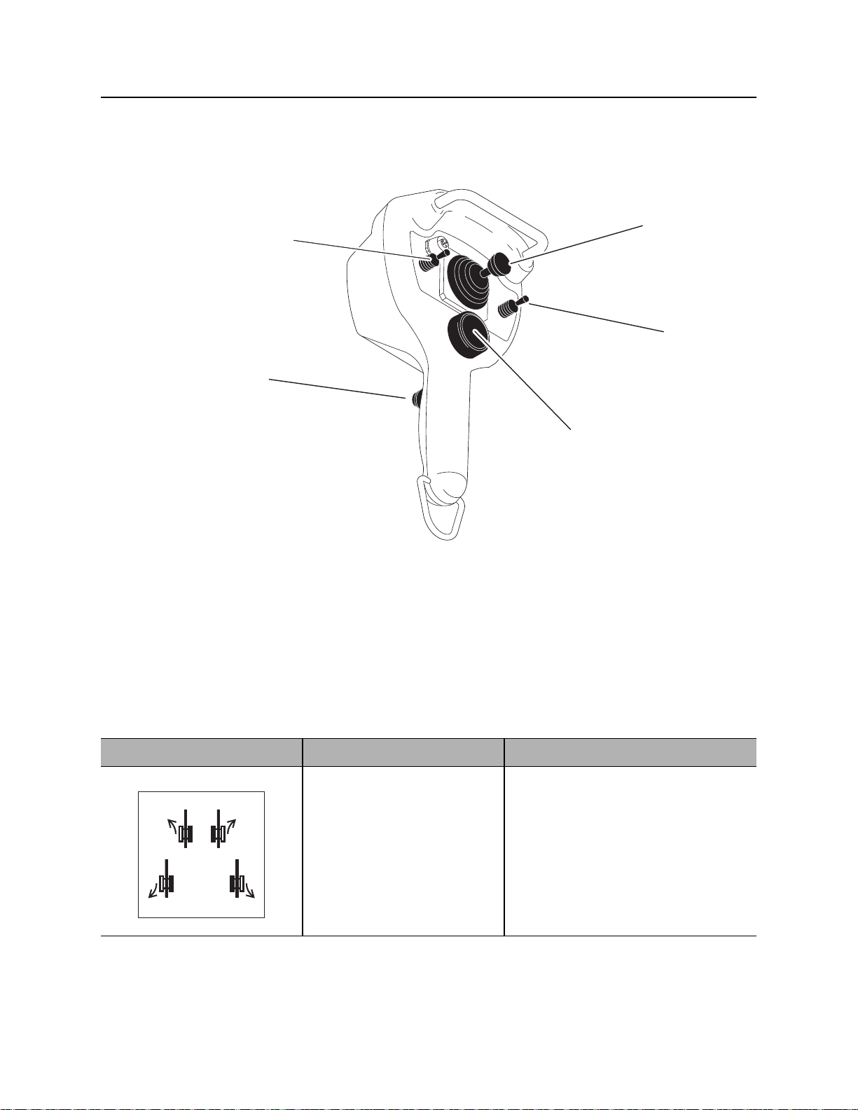
1. Speed/direction control
2. Drive mode switch
3. Remote engine stop
Item Description Notes
1. Speed/direction control To move forward, push.
To move backward, pull.
To steer, move left or right
while moving forward or
backward.
c00ic145h.eps
4. Operator presence switch
5. Throttle switch
IMPORTANT:
• Operator presence switch must
• See “Steer Unit” on page 89 for
be pressed and operator seat
must be empty for control to work.
more information.
CMW
JT30 /JT30 All Terrain Operator’s Manual Controls - 28
Tethered Ground Drive Controller
Item Description Notes
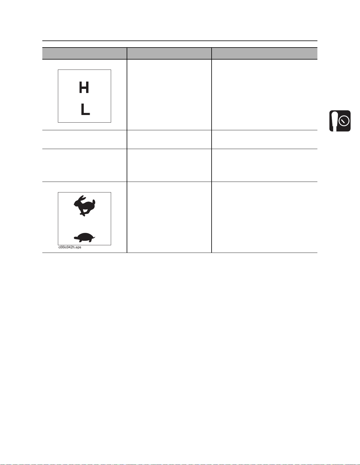
2. Drive mode switch To select normal driving mode
(high), push.
To select loading and
unloading mode (low), pull.
To disable controller, return to
center.
c00ic146h.eps
3. Remote engine stop To stop engine, press red
button.
4. Operator presence
switch
5. Throttle switch To increase engine speed,
To operate ground drive with
tethered controller, press.
To disable controller, release.
press top.
To decrease engine speed,
bottom.
IMPORTANT: To restart engine, turn
ignition switch off and then back on.
CMW
Controls - 29 JT30 /JT30 All Terrain Operator’s Manual
Left Control Console
Left Control Console
Indicators
2
j34om011w.eps
1
7
6
5
34
1. USB port
2. Engine display
3. Hydraulic fluid temperature indicator
4. Hydraulic filter service indicator
Item Description Notes
1. USB port Provides power for mobile
devices.
2. Engine display Communicates status of
engine operation.
CMW
5. Diagnostic port
6. Auxiliary outlet
7. Horn
DC5V, 1A (5W)
See “Engine Display” on page 31.
JT30 /JT30 All Terrain Operator’s Manual Controls - 30
Left Control Console
Item Description Notes
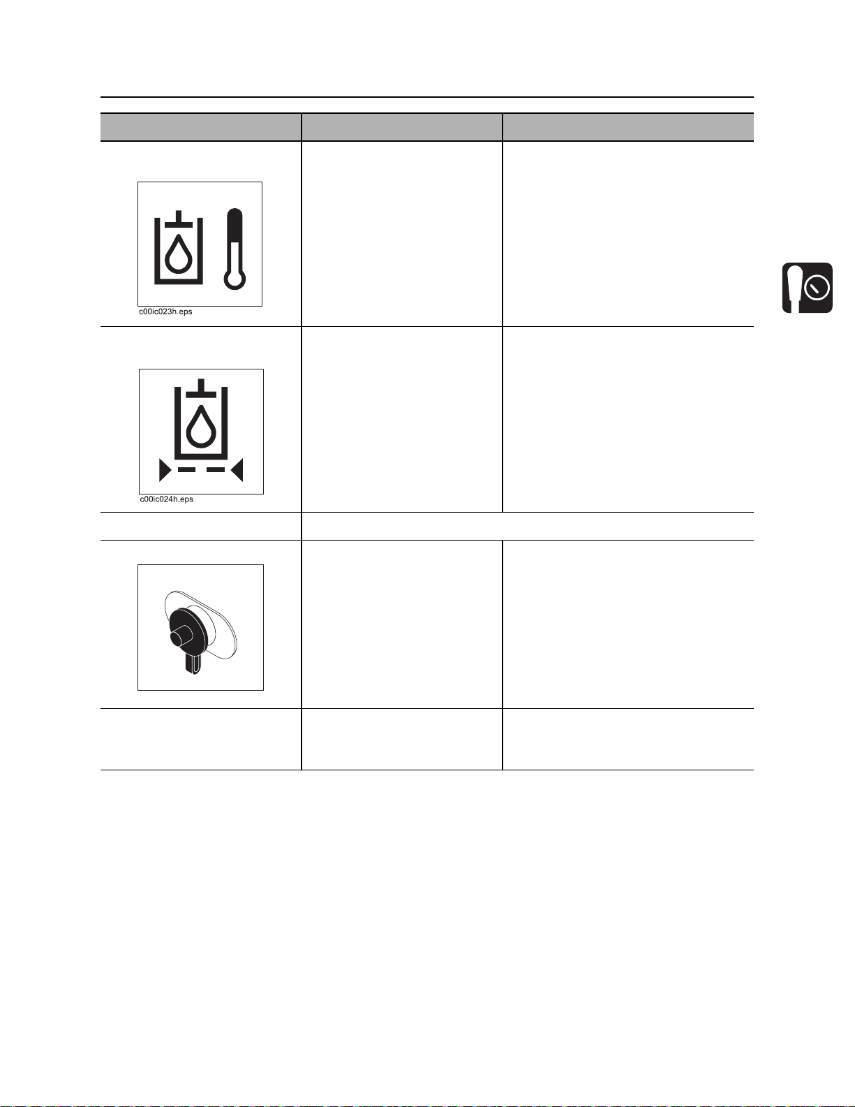
3. Hydraulic fluid
temperature indicator
4. Hydraulic filter service
indicator
5. Diagnostic port For use by only by qualified Ditch Witch technicians.
6. Auxiliary outlet Provides power for other
Indicates hydraulic fluid is
overheating.
Indicates hydraulic fluid filter
needs replacing.
equipment.
Check hydraulic fluid level.
Change filter when indicator lights
continuously and as indicated on
page 218.
Power output is 12VDC, 5A.
c00ic179h.eps
7. Horn Provides audible alarm for
strike system and tracker
control.
CMW

Controls - 31 JT30 /JT30 All Terrain Operator’s Manual
Left Control Console
Engine Display
12
3451
15
10 20
RPM
0% 0 F
525
x100
0
v
0.0
789106
30
0
0 PSI
0.0 H
j34om003w.eps
1. Soft keys
2. Fuel gauge
3. Tachometer
4. Engine coolant temperature gauge
5. Screen brightness (soft key command)
6. Menu key
7. Voltmeter display
8. Hour meter
9. Engine oil pressure gauge
10. Enter key
Item Description Notes
1. Soft keys Press to select a soft key
command.
Soft key commands change with each
menu screen and are displayed next
to the key.
2. Fuel gauge Displays amount of fuel
See “Approved Fuel” on page 202.
remaining in tank.
3. Tachometer Displays engine speed.
CMW

JT30 /JT30 All Terrain Operator’s Manual Controls - 32
Left Control Console
Item Description Notes
4. Engine coolant
temperature gauge
5. Screen brightness soft
key command
6. Menu key Press at any time to return to
7. Voltmeter display Shows system voltage. Normal voltage is 13-14V with engine
8. Hour meter Displays number of hours
9. Engine oil pressure
gauge
10. Enter key Press to finalize a selection. This key may be used for another
Most engine display functions are self-explanatory. For more information about functions, see the
manufacturer’s instructions at www.fwmurphy.com.
Displays engine coolant
temperature.
Displays screen brightness
setting.
main menu.
engine has been running.
Displays engine oil pressure. Full load reading should be 60-80 psi
Normal coolant temperature is 160°212° F (71°-100° C).
To access screen brightness menu,
press soft key. Select day or night
setting.
This key may be used for another
function. If so, a soft key command
will display.
running.
(4.1-5.5 bar).
function. If so, a soft key command
will display.
CMW

Controls - 33 JT30 /JT30 All Terrain Operator’s Manual
Left Control Console
Pipeloading Controls
10
9
8
1
2
3
4
67
j34om002w.eps
1. Pipe lift switch
2. Rear wrench rotation switch
3. Rear wrench clamp switch
4. Front wrench clamp switch
5. Pipe shuttle switch
Item Description Notes
1. Pipe lift switch To raise, press top.
To lower, press bottom.
To stop, release.
6. Pipe gripper switch
7. Pipe lubricator switch
8. Pipe box position switch
9. Add pipe/manual/remove pipe switch
10. Set/Resume switch
5
CMW

JT30 /JT30 All Terrain Operator’s Manual Controls - 34
Left Control Console
Item Description Notes
2. Rear wrench rotation
switch
3. Rear wrench clamp
switch
4. Front wrench clamp
switch
To rotate counterclockwise,
press top.
To rotate clockwise, press
bottom.
To stop rotation, release.
To unclamp, press top.
To clamp, press bottom.
To unclamp, press top.
To clamp, press bottom.
5. Pipe shuttle switch To move toward pipe box,
press top.
To move toward spindle,
press bottom.
To stop shuttles, release.
CMW

Controls - 35 JT30 /JT30 All Terrain Operator’s Manual
Left Control Console
Item Description Notes
6. Pipe gripper switch To close, press top.
To open, press bottom.
To stop grippers, release.
7. Pipe lubricator switch To apply joint compound,
press top.
8. Pipe position switch To shift pipe box away from
operator, press top.
To shift pipe box toward
operator, press bottom.
To stop pipe box, release.
9. Add pipe/manual/
remove pipe switch
To select “add pipe”
automated pipeloader
function, press top.
To use manual pipeloader
controls, move to center.
Applies joint compound to threads at
wrenches.
IMPORTANT: See “Shift Pipe Box” on
page 159.
See “Enable Automated Pipeloader
System” on page 112.
To select “remove pipe”
automated pipeloader
function, press bottom.
10. Set/Resume switch To resume operation or
increase operation levels,
RESUME /
press top.
To set operating conditions or
reduce operation levels,
press bottom.
SET /
c00ic113h.eps
CMW
See “Cruise Control” on page 164.
See “AutoCarve switch” on page 37
and 119.
See “Pipeloader” on page 156.

JT30 /JT30 All Terrain Operator’s Manual Controls - 36
Left Control Console
Drilling/Operation Controls
1
j34om010w.eps
4
5
3
2
6
7
8
9
10
1. Fluid pump speed switch
2. AutoCarve switch
3. Console/Work light switch
4. Engine throttle switch
5. Fluid flow control
6. Remote engine start switch
7. AutoCarve speed control (JT, AT Dirt modes)
Inner spindle speed control (AT Rock mode)
8. Inner spindle switch (AT only)
9. Manual inner spindle control (AT only)
10. Outer spindle brake switch (AT only)
CMW

Controls - 37 JT30 /JT30 All Terrain Operator’s Manual
Left Control Console
Item Description Notes
1. Fluid pump speed
For high speed, press top.
switch
For low speed, press bottom.
2. AutoCarve switch To enable autocarve, press
top.
To deactivate autocarve,
press bottom.
3. Console/Work light
To turn on, press top.
switch
To turn off, press bottom.
High speed delivers more flow at
lower pressure.
Low speed delivers less flow at higher
pressure.
Two-speed thrust is not allowed in
autocarve mode.
Cruise control is not available in
autocarve mode.
Autocarve is disabled while front
wrench is closed.
c00ic151h.eps
4. Engine throttle switch To increase speed, press top.
To enable autothrottle mode,
leave switch in top position.
To disable autothrottle mode,
return switch to center after
desired speed is reached.
To decrease speed, press
bottom.
CMW
Autothrottle mode slows the engine to
low throttle after 15 seconds of
inactivity involving thrust, rotation,
drilling fluid flow, or pipeloader
functions. To return to high speed,
activate thrust, rotation, drilling fluid,
or an add/remove pipe cycle.

JT30 /JT30 All Terrain Operator’s Manual Controls - 38
Left Control Console
Item Description Notes
5. Fluid flow control To increase flow, turn
clockwise.
To decrease flow, turn
counterclockwise.
To stop flow, turn all the way
counterclockwise.
6. Remote engine start
switch
c00ic152h.eps
7. Carve window control
(JT and AT Dirt mode)
or
Inner spindle speed
control (AT Rock mode)
To start engine from
operator’s station, push
button.
Release when engine starts.
To increase carve window
range, turn clockwise.
To decrease carve window
range, turn counterclockwise.
Note: Drilling fluid pump must be
switched on. See “Right Control
Console” on page 40.
IMPORTANT: This button works only
when key in set-up console is on,
operator is in seat, and battery
disconnect switch is closed.
See “Use AutoCarve” on page 119.
For AT units:
To set carve window, autocarve mode
must be enabled and drilling mode
switch in AT Dirt position. See
“Engine Compartment Controls” on
page 60.
To increase rotation speed,
turn clockwise.
To decrease rotation speed,
turn counterclockwise.
8. Inner spindle switch To turn on, press top.
To turn off, move to center.
To manually control inner
rotation speed and direction,
press bottom. Then use
manual inner spindle control
as needed.
To control inner spindle speed, Inner
Spindle switch must be on and drilling
mode switch in AT position. See
“Engine Compartment Controls” on
page 60.
IMPORTANT:
• To restart inner rotation after
operator has left seat, turn inner
rotation off and then on.
• Normal dither works in manual
control mode unless the manual
inner spindle control is moved
from its normal position.
CMW

Controls - 39 JT30 /JT30 All Terrain Operator’s Manual
Left Control Console
Item Description Notes
9. Manual inner spindle
control
10. Outer spindle brake
switch
To rotate clockwise, move to
top.
To rotate counterclockwise,
move to bottom.
To stop inner rotation,
release.
To engage, press top.
To disengage, press bottom.
IMPORTANT:
• Inner spindle switch must be in
manual position for this control to
work.
• Range of speed is reduced to
allow easier manual control.
• Up/down paddle is spring
centered. Moving it above center
rotates inner rod clockwise.
Moving it further rotates the rod
faster. Moving it below center
does the same for counter
clockwise rotation.
Prevents outer spindle from rotating
when inner spindle or mud motor are
in use.
Brake is temporarily released when
front wrench is closed to allow pipe
change.
c00ic255h.eps
CMW

JT30 /JT30 All Terrain Operator’s Manual Controls - 40
Right Control Console
Right Control Console
Controls
1. Carriage control joystick
2. Drilling fluid quick fill switch
3. Remote engine stop switch
4. Drilling fluid pump switch
5. Multi-use button
CMW

Controls - 41 JT30 /JT30 All Terrain Operator’s Manual
Right Control Console
Item Description Notes
1. Carriage control To move carriage forward,
push.
To move carriage backward,
pull.
To rotate spindle
counterclockwise (breakout),
move right.
To rotate spindle clockwise
(makeup), move left.
2. Drilling fluid quick fill
switch
3. Remote engine stop
switch
To override fluid control
setting for full pump flow,
press and hold.
To return fluid flow to flow
control setting, release.
To stop engine, press.
To restart engine, press
remote engine start switch
(page 36).
IMPORTANT: See “Operate Carriage
Control” on page 104 for more
information.
IMPORTANT: Also overrides
temporary fluid shutdown when front
wrench is closed.
IMPORTANT:
• If this switch is used to stop
drilling unit, be sure to turn
ignition switch off if machine will
be left unattended for long
periods of time. Battery discharge
can occur.
4. Drilling fluid pump
switch
CMW
• If wrenches are engaged when
remote stop is pressed, wrenches
will remain engaged but could
gradually open.
To turn on, press once.
To turn off, press once.

JT30 /JT30 All Terrain Operator’s Manual Controls - 42
Right Control Console
Item Description Notes
5. Multi-use button To engage a function, push
and hold.
To return to normal operation,
release.
Operation Options
• Two-speed carriage control
• Fine adjustment for cruise and
autocarve mode
• Autocarve reaming and
positioning functions
• Automated add pipe for pipes in
delivery chute
• Jammed collar separation (AT
only)
• Failed makeup system override
• Single pipe loader reset
CMW

Controls - 43 JT30 /JT30 All Terrain Operator’s Manual
Right Control Console
Indicators
1. Main controller diagnostic light (red)
2. Pipeloader diagnostic light (red)
3. Operator presence indicator
4. (blank)
5. Front wrench status indicator
6. Shuttle home status indicator
CMW
7. Carriage home status indicator
8. Rear stop status indicator
9. Pipe lift status indicator
10. Front pipe box status indicator
11. Rear pipe box status indicator
12. Fluid pump status indicator

JT30 /JT30 All Terrain Operator’s Manual Controls - 44
Right Control Console
Item Description Notes
1. Main controller
diagnostic light (red)
2. Pipeloader diagnostic
light (red)
If system is OK, light should
be off.
If system is not getting power,
light should be on.
If a non-essential diagnostic
code is recorded, light should
flash on and off for 10
seconds.
If an essential diagnostic
code is recorded, light should
repeatedly flash on for three
seconds and off for half a
second.
If system is OK, light should
be off.
If system is not getting power,
light should be on.
If a non-essential diagnostic
code is recorded, light should
flash on and off for 10
seconds.
See “Machine Diagnostic Codes” on
page 177.
See “Machine Diagnostic Codes” on
page 177.
3. Operator presence
indicator
4. (Blank)
If an essential diagnostic
code is recorded, light should
repeatedly flash on for three
seconds and off for half a
second.
Lights when operator is
seated in operator’s station.
Thrust and rotation will not operate
unless light is on.
CMW

Controls - 45 JT30 /JT30 All Terrain Operator’s Manual
Right Control Console
Item Description Notes
5. Front wrench status
indicator
6. Shuttle home status
indicator
7. Carriage home status
indicator
If front wrench is closed, light
should be on.
If front wrench is open, light
should be off.
If shuttle is retracted, light
should be on.
If shuttle is not completely
retracted, light should be off.
If carriage is in the home
zone at either end of drill
frame, light should be on.
8. Rear stop status
indicator
If carriage is not in the home
zone at either end of drill
frame, light should be off.
If carriage is at very back of
drill frame, light should be on.
If carriage is away from very
back of drill frame, light
should be off.
IMPORTANT: The stop sensor is
used to determine when to stop
carriage when backing up.
CMW

JT30 /JT30 All Terrain Operator’s Manual Controls - 46
Right Control Console
Item Description Notes
9. Pipe lift status indicator If pipe lifter is lifted fully and
lift pressure switch is
engaged, light should be on.
If pipe lift pressure switch is
not engaged, light should be
off.
10. Front pipe box status
indicator
11. Rear pipe box status
indicator
12. Fluid pump status
indicator
If active pipe column contains
pipe, light should be on.
If active pipe column does not
contain pipe, light should be
off.
If active pipe column contains
pipe, light should be on.
If active pipe column does not
contain pipe, light should be
off.
If fluid pump is on, light
should be on.
IMPORTANT:
• Check pipe box status lights to
see when active column of pipe
box is empty. See “Shift Pipe Box”
on page 159.
• One light on and one light off
indicates a jammed pipe. See
“Correct Misaligned or Jammed
Pipe” on page 160.
IMPORTANT:
• Check pipe box status lights to
see when active column of pipe
box is empty. See “Shift Pipe Box”
on page 159.
• One light on and one light off
indicates a jammed pipe. See
“Correct Misaligned or Jammed
Pipe” on page 160.
NOTICE: Do not run fluid pump
without fluid.
If fluid pump is off, light
should be off.
CMW

Controls - 47 JT30 /JT30 All Terrain Operator’s Manual
3
60
1
2
4
5
x1000
PSI
0
6
12
18
24
30
36
42
KPs
Right Control Console
Gauges
1. Outer rotation pressure gauge
2. Thrust/pullback pressure gauge
3. Fluid pressure gauge
4. Inner rotation pressure gauge (AT only)
Item Description Notes
1. Outer rotation pressure
gauge
24
18
12
30
36
42
KPs
x1000
PSI
c00ic660w.eps
CMW
Displays hydraulic pressure in
outer rotation circuit.

JT30 /JT30 All Terrain Operator’s Manual Controls - 48
3
60
1
2
4
5
x1000
PSI
0
6
12
18
24
30
36
42
KPs
10
20
0
0
20
40
60
80
100
120
140
KPs
5
15
x100
PSI
Right Control Console
Item Description Notes
2. Thrust/pullback
pressure gauge
24
18
12
30
36
42
x1000
PSI
c00ic659w.eps
KPs
3. Drilling fluid pressure
gauge
10
80
60
40
100
15
x100
120
140
20
KPs
20
PSI
c00ic658w.eps
4. Inner rotation pressure
gauge (AT only)
Displays hydraulic pressure in
thrust/pullback circuit.
Displays hydraulic pressure in
drill fluid circuit.
Displays hydraulic pressure in
inner rotation circuit.
NOTICE: Monitor this gauge and
drilling fluid flowmeter carefully to see
if values are rising and falling at the
same time. If they are not, nozzle
might be plugged or fluid supply
depleted.
CMW

Controls - 49 JT30 /JT30 All Terrain Operator’s Manual
Information Center
Information Center
Displays
j34om004w.eps
1. Float sensor display
2. ESID display
3. Drilling fluid flow display
4. Outer rotation speed display
5. Inner rotation speed display
Item Description Notes
6. Operation and exception message display
7. Pipeloader message display
8. Diagnostic message display
9. Active display indicator
10. Diagnostic indicator
!
1. Float sensor display Displays the position of the
carriage float sensor.
CMW
When threading and unthreading a
pipe joint, float should generally be in
middle of range.

JT30 /JT30 All Terrain Operator’s Manual Controls - 50
Information Center
Item Description Notes
2. ESID display Displays the ESID
information.
3. Drilling fluid flow
display
4. Outer rotation speed
display
5. Inner rotation speed
display
6. Operation and
exception message
display
7. Pipeloader message
display
Displays the estimated GPM
or LPM of drilling fluid being
pumped.
Displays the measured RPM
of outer rotation pipe.
Displays the measured RPM
of inner rotation rod (AT only).
Displays status of cruise
control, carve mode, drill fluid,
tracker control, diagnostic test
mode and service mode.
Displays messages related to
add or remove pipe cycles.
Displays diagnostic
information when unit is in
service mode.
IMPORTANT: If a strike is detected,
the bottom portion of the display
automatically switches to the ESID
information display.
Displays exception messages when a
requested function is blocked due to a
conflicting condition.
8. Diagnostic message
display
9. Active display indicator Indicates that information
10. Diagnostic indicator Indicates diagnostic codes
Displays messages related to
diagnostic information of
machine.
center display is operating.
(dc) from main controller,
ESID, or Information Center.
IMPORTANT: If nothing is changing
on the display except this indicator,
communications may have stopped.
Device shown is the source of the
diagnostic code shown.
CMW

Controls - 51 JT30 /JT30 All Terrain Operator’s Manual
Information Center
Soft Keys
Keys F1-F6 can be assigned different functions based on which display is selected. Pressing any of the
assigned keys may reassign any key as needed for the new display.
1
!
23456
j34om005w.eps
The soft keys are described below as they are assigned (shown) in the diagram, but can have many other
configurations that are not shown here.
1. Clear button
2. Module button
3. No buz / Buz on button
Item Description Notes
1. Clear button Press button to clear a
diagnostic code or return to
the previous screen.
4. Pipe counter button
5. (not used)
6. Fluid usage button
IMPORTANT: Removes diagnostic
code from the display but does not
clear the code.
CMW

JT30 /JT30 All Terrain Operator’s Manual Controls - 52
Information Center
Item Description Notes
2. Module button Use to see more specific
information about the
Information Center, ESID,
Main, or Pipeloader
controllers.
3. No buz / Buz on button Toggles indicator (intermittent
buzzer) off or on for reminder
when key is on but engine is
not running.
4. Pipe counter button Displays pipe count in lower
part of display to allow
operator to count pipe while
drilling and backreaming.
Push to show pipe count and
pipe control buttons.
5. F5 button Has no functionality at this
time.
6. Fluid usage button Displays an estimate of
drilling fluid used since last
reset.
Provides access to individual
components in the system.
IMPORTANT: If the key is left on,
battery will discharge.
Pipe counter only works when running
automated add pipe or remove pipe
cycles. If changing pipe manually,
counter will not increase or decrease.
Can display both positive and
negative counts. Operator can
manually increase, decrease, or reset
pipe count if desired.
Operator can reset estimated amount.
CMW

Controls - 53 JT30 /JT30 All Terrain Operator’s Manual
Anchoring System Console
Anchoring System Console
j34om012w.eps
1. Left rotation control
2. Left thrust control
Item Description Notes
1. Left rotation control To remove anchor, push.
To drive anchor, pull.
3. Right rotation control
4. Right thrust control
See “Anchor System” on page 130.
CMW

JT30 /JT30 All Terrain Operator’s Manual Controls - 54
Anchoring System Console
Item Description Notes
2. Left thrust control To move anchor up, push.
To move anchor down, pull.
3. Right rotation control To remove anchor, push.
To drive anchor, pull.
4. Right thrust control To move anchor up, push.
To move anchor down, pull.
See “Anchor System” on page 130.
See “Anchor System” on page 130.
See “Anchor System” on page 130.
CMW

Controls - 55 JT30 /JT30 All Terrain Operator’s Manual
Seat/Armrest
Seat/Armrest
1. Seat recline control 2. Seat slide control
Item Description Notes
1. Seat recline control To recline or raise seatback,
lift.
To lock seatback in position,
release.
CMW

JT30 /JT30 All Terrain Operator’s Manual Controls - 56
Seat/Armrest
Item Description Notes
2. Seat slide control To slide forward or backward,
move left.
To lock seat in position, move
right.
CMW

Controls - 57 JT30 /JT30 All Terrain Operator’s Manual
Cab Controls (optional)
Cab Controls (optional)
1. Air conditioner on/off switch
2. Air conditioner temperature dial
3. Air conditioner fan speed dial
4. Emergency glass breaker
Item Description Notes
1. AC on/off switch To turn air conditioner on,
press right.
To turn air conditioner off,
press left.
CMW
5. Dome light switch
6. Heater temperature dial
7. Heater fan speed dial

JT30 /JT30 All Terrain Operator’s Manual Controls - 58
Cab Controls (optional)
Item Description Notes
2. AC temperature dial To adjust air temperature,
turn dial.
3. AC fan speed dial To adjust fan speed, turn dial.
4. Glass breaker Use breaker to break glass if
door becomes inoperable.
5. Dome light switch To turn on dome light, press
right.
To turn off dome light, press
left.
NOTICE: Only the rear and left
windows are fitted with true glass.
Hammer may not work on front and
right windows, which are acrylic.
CMW

Controls - 59 JT30 /JT30 All Terrain Operator’s Manual
Cab Controls (optional)
Item Description Notes
6. Heater temperature dial To adjust heater temperature,
turn dial.
7. Heater fan speed dial To adjust heater fan speed,
turn dial.
CMW

JT30 /JT30 All Terrain Operator’s Manual Controls - 60
Engine Compartment Controls
Engine Compartment Controls
j34om006w.eps
123 7 6
54
89
1. Throttle switch
2. Drilling mode switch (AT units only)
3. Fan speed switch
4. EDT diagnostic port, main controller
5. J1939 CAN diagnostic port, engine
6. Inner rotation hour meter
7. Battery disconnect switch
8. EDT diagnostic port, tether controller
9. Air intake service indicator
CMW

Controls - 61 JT30 /JT30 All Terrain Operator’s Manual
Engine Compartment Controls
Item Description Notes
1. Throttle switch To increase engine speed,
press top.
To decrease engine speed,
press bottom.
To further increase or
decrease speed, press
additional times (or hold until
c00ic243h.eps
2. Drilling mode switch
(AT only)
desired speed is reached).
To select AT Rock mode,
press top.
To select AT Dirt mode, move
to middle.
To select JT mode, press
bottom.
3. Fan speed switch For high speed, press top.
For automatic speed, press
bottom.
Use this switch only if throttle switch
on console does not work.
Use AT Rock mode when using AT
pipe with inner rod and rock drilling
bits.
Use AT Dirt mode when using AT
pipe with inner rod and adapter to use
dirt tool head.
Use JT drilling mode when using JT
pipe without inner rod.
IMPORTANT: If switch is on high
speed, fan will run at full speed all the
time. If switch is on auto speed, fan
speed will vary in relation to engine
temperature.
4. EDT diagnostic port,
main controller
5. J1939 CAN diagnostic
port, engine
CMW
For use only by qualified Ditch Witch technicians.
For use only by qualified Ditch Witch technicians.

JT30 /JT30 All Terrain Operator’s Manual Controls - 62
Engine Compartment Controls
Item Description Notes
6. Inner rotation hour
meter
c00ic259h.eps
7. Battery disconnect
switch
8. EDT diagnostic port,
tether controller
Displays inner rotation
operating time hours.
To connect, move clockwise.
To disconnect, move
counterclockwise.
For use only by qualified Ditch Witch technicians.
Use to determine service intervals.
9. Air intake restriction
indicator
Shows air intake restriction. Replace the air filter elements when
the indicator reaches the red zone.
See “Change Air Filter” on page 231.
CMW

Controls - 63 JT30 /JT30 All Terrain Operator’s Manual
Engine Compartment Controls
CMW

JT30 /JT30 All Terrain Operator’s Manual Operation Overview - 64
Operation Overview
Chapter Contents
Planning. . . . . . . . . . . . . . . . . . . . . . . . . . . . . . . . . . 65
Setting Up at Jobsite . . . . . . . . . . . . . . . . . . . . . . . 65
Drilling . . . . . . . . . . . . . . . . . . . . . . . . . . . . . . . . . . . 66
Backreaming . . . . . . . . . . . . . . . . . . . . . . . . . . . . . . 67
Leaving Jobsite. . . . . . . . . . . . . . . . . . . . . . . . . . . . 67
Storing Equipment . . . . . . . . . . . . . . . . . . . . . . . . . 67
CMW

Operation Overview - 65 JT30 /JT30 All Terrain Operator’s Manual
Planning
Planning
1. Gather information about jobsite. See page 70.
2. Inspect jobsite. See page 71.
3. Classify jobsite. See page 73.
4. Plan bore path. See page 75.
5. Check supplies and prepare equipment. See page 86.
6. Load equipment. See page 94.
Setting Up at Jobsite
1. Prepare jobsite. See page 85.
2. Mix drilling fluid. page 138
3. Unload drilling unit from trailer. See page 97.
4. Assemble drill string. See page 106.
5. Position drilling unit and drill frame. See page 102.
6. Assemble strike system. See page 132.
7. Anchor drilling unit. See page 130.
8. Connect fluid system. See page 102.
9. Calibrate tracker with beacon that will be installed in beacon housing. See tracker operator’s manual.
CMW

JT30 /JT30 All Terrain Operator’s Manual Operation Overview - 66
Drilling
Drilling
1. Start system. See page 102.
2. Engage tracker control if desired. See page 143.
3. Drill first pipe. See page 111.
4. Record bore path. See page 121.
5. Enable automated pipeloader system. See page 112.
6. Add pipe. See page 113.
7. Drill remaining pipes in pipe box.
• Correct direction. See page 117.
• Engage cruise control. See page 164.
• Shift pipe box. See page 159.
8. Add additional drill pipe to empty box (see page 161) to complete bore.
9. Surface drill head. See page 121.
• Remove drill head.
• Grease downhole tool (AT mode).
CMW

Operation Overview - 67 JT30 /JT30 All Terrain Operator’s Manual
Backreaming
Backreaming
1. Assemble backream string. See page 123.
2. Start drilling unit and adjust throttle.
3. Set drilling fluid flow. Check that fluid flows through all nozzles.
4. Remove extra drill pipe from pipe box (see page 163) to complete backream.
5. Remove remaining pipe to complete backream.
6. Remove pullback device. See page 127.
Backreaming Tips
• Plan backreaming job before drilling. Plan bore path as straight as possible. Check bend limits of
pullback material. Check that appropriate pullback devices are on hand.
• Keep all bends as gradual as possible.
• Drilling fluid quality is a key factor in backreaming success. Contact your Ditch Witch dealer for
information on testing water, selecting additives, and mixing drilling fluid.
• Backreaming requires more fluid than drilling. Make sure enough fluid is used.
Leaving Jobsite
1. Remove downhole tools.
2. Remove anchors. See page 132.
3. Rinse unit and downhole tools. See page 192.
4. Disassemble strike system and disconnect from fluid system. See page 132.
5. Stow tools. See page 194.
6. Load unit onto trailer. See page 94.
Storing Equipment
1. For cold weather storage, antifreeze drilling unit. See
2. .
3. For long-term storage, disconnect battery disconnect switch.
CMW

JT30 /JT30 All Terrain Operator’s Manual Prepare - 68
Prepare
Chapter Contents
Gather Information . . . . . . . . . . . . . . . . . . . . . . . . . 70
• Review Job Plan . . . . . . . . . . . . . . . . . . . . . . . . . . . . . . . . . . . . . . . . . . 70
• Notify One-Call Services. . . . . . . . . . . . . . . . . . . . . . . . . . . . . . . . . . . . 70
• Examine Pullback Material . . . . . . . . . . . . . . . . . . . . . . . . . . . . . . . . . . 70
• Arrange for Traffic Control. . . . . . . . . . . . . . . . . . . . . . . . . . . . . . . . . . . 70
• Plan for Emergency Services . . . . . . . . . . . . . . . . . . . . . . . . . . . . . . . . 70
Inspect Site . . . . . . . . . . . . . . . . . . . . . . . . . . . . . . . 71
• Identify Hazards . . . . . . . . . . . . . . . . . . . . . . . . . . . . . . . . . . . . . . . . . . 71
• Select Start and End Points . . . . . . . . . . . . . . . . . . . . . . . . . . . . . . . . . 72
Classify Jobsite. . . . . . . . . . . . . . . . . . . . . . . . . . . . 73
• Inspect Jobsite . . . . . . . . . . . . . . . . . . . . . . . . . . . . . . . . . . . . . . . . . . . 73
• Select a Classification. . . . . . . . . . . . . . . . . . . . . . . . . . . . . . . . . . . . . . 73
• Apply Precautions. . . . . . . . . . . . . . . . . . . . . . . . . . . . . . . . . . . . . . . . . 74
Plan Bore Path . . . . . . . . . . . . . . . . . . . . . . . . . . . . 75
• Recommended Bend Limits . . . . . . . . . . . . . . . . . . . . . . . . . . . . . . . . . 76
• Entry Pitch. . . . . . . . . . . . . . . . . . . . . . . . . . . . . . . . . . . . . . . . . . . . . . . 81
• Minimum Setback . . . . . . . . . . . . . . . . . . . . . . . . . . . . . . . . . . . . . . . . . 81
• Minimum Depth. . . . . . . . . . . . . . . . . . . . . . . . . . . . . . . . . . . . . . . . . . . 82
• Bore Path Calculator. . . . . . . . . . . . . . . . . . . . . . . . . . . . . . . . . . . . . . . 82
CMW

Prepare - 69 JT30 /JT30 All Terrain Operator’s Manual
Prepare Jobsite. . . . . . . . . . . . . . . . . . . . . . . . . . . . 85
• Mark Bore Path. . . . . . . . . . . . . . . . . . . . . . . . . . . . . . . . . . . . . . . . . . . 85
• Prepare Entry Point. . . . . . . . . . . . . . . . . . . . . . . . . . . . . . . . . . . . . . . . 85
Check Supplies and Prepare Equipment . . . . . . . 86
• Check Supplies. . . . . . . . . . . . . . . . . . . . . . . . . . . . . . . . . . . . . . . . . . . 86
• Prepare Equipment. . . . . . . . . . . . . . . . . . . . . . . . . . . . . . . . . . . . . . . . 87
• Assemble Accessories . . . . . . . . . . . . . . . . . . . . . . . . . . . . . . . . . . . . . 87
CMW

JT30 /JT30 All Terrain Operator’s Manual Prepare - 70
Gather Information
Gather Information
A successful job begins before the bore. The first step in planning is reviewing information already
available about the job and jobsite.
Review Job Plan
Review blueprints or other plans and make sure you have taken bore enlargement during backreaming
and pullback into account. Check for information about existing or planned structures, elevations, or
proposed work that may be taking place at the same time.
Notify One-Call Services
Contact your local One-Call (811 in USA) or the One-Call referral number (888-258-0808 in USA and
Canada) to have underground utilities located before digging. Also contact any utilities that do not
participate in the One-Call service.
Examine Pullback Material
Ask for a sample of the material you will be pulling back. Check its weight and stiffness. Contact the
manufacturer for bend radius information. Check that you have appropriate pullback devices.
Arrange for Traffic Control
If working near a road or other traffic area, contact local authorities about safety procedures and
regulations.
Plan for Emergency Services
Have the telephone numbers for local emergency and medical facilities on hand. Check that you will have
access to a telephone.
CMW

Prepare - 71 JT30 /JT30 All Terrain Operator’s Manual
Inspect Site
Inspect Site
Inspect jobsite before transporting equipment. Check for the following:
• overall grade or slope
• changes in elevation such as hills or open trenches
• obstacles such as buildings, railroad crossings, or streams
• signs of utilities (See “Inspect Jobsite” on page 73.)
• traffic
• access
• soil type and condition
• water supply
• sources of locator interference (rebar, railroad tracks, etc.)
Take soil samples from several locations along bore path to determine best bit and backreamer
combinations.
Identify Hazards
Identify safety hazards and classify jobsite. See “Classify Jobsite” on page 73.
Jobsite hazards could cause death or serious injury. Use
correct equipment and work methods. Use and maintain proper safety
equipment.
To help avoid injury:
• Wear personal protective equipment including hard hat, safety eye wear, and hearing protection.
• Do not wear jewelry or loose clothing.
• Notify One-Call and companies which do not subscribe to One-Call.
• Comply with all utility notification regulations before digging or drilling.
• Verify location of previously marked underground hazards.
• Mark jobsite clearly and keep spectators away.
Remember, jobsite is classified by hazards in place -- not by line being installed.
CMW

JT30 /JT30 All Terrain Operator’s Manual Prepare - 72
Inspect Site
Select Start and End Points
Select one end to use as a starting point. Consider the following when selecting a starting point:
Slope
Fluid system should be parked on a level site. Consider how slope will affect drilling unit setup, bending
pipe, and fluid flow out of hole.
Traffic
Vehicle and pedestrian traffic must be a safe distance from drilling equipment. Allow at least 10’ (3 m)
buffer zone around equipment.
Space
Check that starting and ending points allow enough space for gradual pipe bending. See “Minimum
Setback” on page 81.
Check that there is enough space to work and to set up electric strike system.
Comfort
Consider shade, wind, fumes, and other site features.
Drill downhill when possible so fluid will flow away from drilling unit.
CMW

Prepare - 73 JT30 /JT30 All Terrain Operator’s Manual
Classify Jobsite
Classify Jobsite
Inspect Jobsite
• Follow U.S. Department of Labor regulations on excavating and trenching (Part 1926, Subpart P) and
other similar regulations.
• Contact your local One-Call (811 in USA) or the One-Call referral number (888-258-0808 in USA and
Canada) to have underground utilities located before digging. Also contact any utilities that do not
participate in the One-Call service.
• Inspect jobsite and perimeter for evidence of underground hazards, such as:
– “buried utility” notices
– utility facilities without overhead lines
– gas or water meters
– junction boxes
– drop boxes
– light poles
– manhole covers
– sunken ground
• Have an experienced locating equipment operator sweep area within 20’ (6 m) to each side of trench
bore path. Verify previously marked line and cable locations.
• Mark location of all buried utilities and obstructions.
• Classify jobsite.
Select a Classification
Jobsites are classified according to underground hazards present.
If working . . . then classify jobsite as . . .
within 10’ (3 m) of a buried electric line electric
within 10’ (3 m) of a natural gas line natural gas
in concrete, sand, or granite which is capable of producing
crystalline silica (quartz) dust
within 10’ (3 m) of any other hazard other
NOTICE: If you have any doubt about jobsite classification, or if jobsite might contain unmarked
hazards, take steps outlined previously to identify hazards and classify jobsite before working.
crystalline silica (quartz) dust
CMW

JT30 /JT30 All Terrain Operator’s Manual Prepare - 74
Classify Jobsite
Apply Precautions
Once classified, precautions appropriate for jobsite must be taken.
Electric Jobsite Precautions
Use one or both of these methods.
• Expose line by careful hand digging or soft excavation. Use beacon to track bore path.
• Have service shut down while work is in progress. Have electric company test lines before returning
them to service.
Natural Gas Jobsite Precautions
Position equipment upwind from gas lines and use one or both of these methods.
• Expose lines by careful hand digging or soft excavation. Use beacon to track bore path.
• Have gas shut off while work is in progress. Have gas company test lines before returning them to
service.
Crystalline Silica (Quartz) Dust Precautions
Crystalline silica dust is a naturally occur i ng substance found in soil, sand, concrete, granite, and quartz.
Breathing silica dust particles while cutting, drilling, or working materials may cause lung disease or
cancer. To reduce exposure:
• Use water spray or other means to control dust.
• Refer to U.S. Department of Labor Occupational Safety and Health Administration guidelines to learn
more about appropriate breathing protection and permissible exposure limits.
Other Jobsite Precautions
You may need to use different methods to safely avoid other underground hazards. Talk with those
knowledgeable about hazards present at each site to determine which precautions should be taken or if
job should be attempted.
CMW

Prepare - 75 JT30 /JT30 All Terrain Operator’s Manual
Plan Bore Path
Plan Bore Path
Plan the bore path, from entry to end, before drilling begins. The Ditch Witch Trac Management System
Plus is available for planning your bore path. This special software can be run in the field using a laptop
computer equipped with Windows
If not using Trac Management System Plus, mark the bore path on the ground with spray paint or flags, or
record it on paper for operator reference.
For complicated bores, consult an engineer. Have the jobsite surveyed and bore path calculated. Be sure
the engineer knows minimum entry pitch, bend limits of drill pipe, bend and tension limits of pullback
material, pipe lengths, and location of all underground utilities.
For less complicated bores, plan the bore based on four measurements:
• recommended bend limit
• entry pitch
• minimum setback
• minimum depth
®
95 or higher operating system. See your Ditch Witch dealer for details.
IMPORTANT: See the following pages for more information about these measurements. If not using
Trac Management System Plus, see “Bore Path Calculator” on page 82 and use these measurements to
help plan your bore.
CMW

JT30 /JT30 All Terrain Operator’s Manual Prepare - 76
Plan Bore Path
Recommended Bend Limits
Ditch Witch drill pipes are designed to bend slightly during operation. Slight bending allows for steering and
correcting direction. Bending beyond recommended limits will cause damage that might not be visible. This
damage adds up and will later lead to sudden drill pipe failure.
IMPORTANT: Consider recommended bend limits during any bend, not just during bore entry.
Pipe Pitch
Ditch Witch drill pipe is tested to bend at a maximum
percent pitch.
Make sure pitch (A) changes no more than the
following percentages over the full length of each pipe.
JT pipe AT pipe AT cobble pipe
6.5% 6.4% 4.4%
NOTICE: Bending drill pipe more sharply than recommended will damage pipe and cause failure over
time. Changes in pitch must be equally distributed over the length of a pipe. Maximum changes in
pitch within 1-2’ (300-600 mm) of pipe create sharp bends that will damage pipe.
Monitor the pitch of each pipe with the tracker remote display on the operator’s console.
CMW

Prepare - 77 JT30 /JT30 All Terrain Operator’s Manual
Plan Bore Path
Bend Radius
JT
JT30 drill pipes have a tested minimum bend radius of
155’ (44.2 m). This means that a 90-degree bend in
the bore path:
• has a radius (A) of 155’ (44.2 m)
• requires approximately 243’ (74 m) of drill pipe
(B).
AT
JT30 All Terrain drill pipes have a tested minimum
bend radius of 145’ (47.2 m). This means that a 90degree bend in the bore path:
• has a radius (A) of 145’ (47.2 m)
• requires approximately 228’ (69.5 m) of drill pipe (B).
AT Cobble
JT30 All Terrain cobble drill pipes have a tested minimum bend radius of 210’ (64 m). This means that a
90-degree bend in the bore path:
• has a radius (A) of 145’ (47.2 m)
• requires approximately 330’ (100.5 m) of drill pipe (B).
NOTICE: Bending drill pipe more sharply than recommended will damage the pipe and cause failure
over time.
• If bend radius is reduced, drill pipe life is reduced.
• If bend radius is increased, drill pipe life is increased.
IMPORTANT: Use the charts on the next page to keep bends within safe limits.
CMW

JT30 /JT30 All Terrain Operator’s Manual Prepare - 78
Plan Bore Path
Pipe-By-Pipe Bend Limits
JT pipe
Pipe
(C)
1 9’ 10” (3.0 m) 0’ 3.7” (0.1 m) 14 120’ 4.2” (36.7 m) 57’ 3.8” (17.5 m)
2 19’ 7.6” (6.0 m) 1’ 3” (0.4 m) 15 126’ 3.7” (38.5 m) 65’ 1.9” (19.9 m)
3 29’ 4.2” (8.9 m) 2’ 9.6” (0.9 m) 16 131’ 9” (40.2 m) 73’ 4.2” (22.4 m)
4 38’ 11.4” (11.9 m) 4’ 11.7” (1.5 m) 17 136’ 8” (41.7 m) 81’ 10.5” (25.0 m)
5 48’ 4.7” (14.7 m) 7’ 9” (2.3 m) 18 141’ 0.4” (43.0 m) 90’ 8.3” (27.6 m)
6 57’ 7.6” (17.6 m) 11’ 1.4” (3.4 m) 19 144’ 9.9” (44.1 m) 99’ 9.3” (30.4 m)
7 66’ 7.8” (20.3 m) 15’ 0.7” (4.6 m) 20 148’ 0.5” (45.1 m) 109’ 0.9” (33.2 m)
8 75’ 4.8” (23.0 m) 19’ 6.9” (6.0 m) 21 150’ 7.9” (45.9 m) 118’ 6.8” (36.1 m)
9 83’ 10.1” (25.6 m) 24’ 7.6” (7.5 m) 22 152’ 8” (46.5 m) 128’ 2.4” (39.1 m)
10 91’ 11.3” (28.0 m) 30’ 2.6” (9.2 m) 23 154’ 0.7” (47 m) 137’ 11.3” (42.0 m)
11 99’ 8.1” (30.4 m) 36’ 3.6” (11.1 m) 24 154’ 10” (47.2 m) 147’ 9” (45.0 m)
12 107’ 0.1” (32.6 m) 42’ 10.4” (13.1 m) 25 155’ (47.2 m) 155’ (47.2 m)
13 113’ 10.9” (34.7 m) 49’ 10.6” (15.2 m)
Forward (B) Deflection (A) Pipe
(C)
Forward (B) Deflection (A)
j22om001t.eps
C
1
15.2m
49ft. 10.6in.
13
47.2m
155ft.
A
Pipe 13 is illustrated.
25
47.2m
155ft.
34.7m
113ft. 10.9in.
B
CMW

Prepare - 79 JT30 /JT30 All Terrain Operator’s Manual
Plan Bore Path
AT Pipe
Pipe
(C)
1 9’ 4.7” (2.9 m) 0’ 3.7” (0.1 m) 13 108’ 2.9” (33.0 m) 48’ 6.2” (14.8 m)
2 18’ 9” (5.7 m) 1’ 2.6” (0.4 m) 14 114’ 3.2” (34.8 m) 55’ 8.8” (17.0 m)
3 28’ 0.3” (8.5 m) 2’ 8.8” (0.8 m) 15 119’ 9.7” (36.5 m) 63’ 3.8” (19.3 m)
4 37’ 2.2” (11.3 m) 4’ 10.2” (1.5 m) 16 124’ 10.1” (38.1 m) 71’ 3” (21.7 m)
5 46’ 2.2” (14.1 m) 7’ 6.6” (2.3 m) 17 129’ 4.3” (39.4 m) 79’ 6” (24.2 m)
6 54’ 11.9” (16.8 m) 10’ 10” (3.3 m) 18 133’ 4” (40.7 m) 88’ 0.2” (26.8 m)
7 63’ 6.8” (19.4 m) 14’ 8.1” (4.5 m) 19 136’ 8.9” (41.7 m) 96’ 9.3” (29.5 m)
8 71’ 10.5” (21.9 m) 19’ 0.8” (5.8 m) 20 139’ 7” (42.5 m) 105’ 8.8” (32.2 m)
9 79’ 10.6” (24.3 m) 23’ 11.9” (7.3 m) 21 141’ 10” (43.2 m) 114’ 10.3” (35.0 m)
10 87’ 6.6” (26.7 m) 29’ 5” (9.0 m) 22 143’ 5.8” (43.7 m) 124’ 1.3” (37.9 m)
11 94’ 10.3” (28.9 m) 35’ 4” (10.8 m) 23 144’ 6.5” (44.1 m) 133’ 5.4” (40.7 m)
12 101’ 9.1” (31.0 m) 41’ 8.5” (12.7 m) 24 145’ (44.2 m) 145’ (44.2 m)
Forward (B) Deflection (A) Pipe
(C)
Forward (B) Deflection (A)
24
j22om002t.eps
C
1
12.7m
41ft. 8.5in.
12
44.2m
145ft.
A
Pipe 12 is illustrated.
31m
101ft. 9.1in.
44.2m
145ft.
B
CMW

JT30 /JT30 All Terrain Operator’s Manual Prepare - 80
Plan Bore Path
AT cobble pipe
Pipe
(C)
1 9’ 4.8” (2.9 m) 0’ 2.5” (0.1 m) 19 157’ 10” (48.1 m) 71’ 5.7” (21.8 m)
2 18’ 9.3” (5.7 m) 0’ 10.1” (.3 m) 20 163’ 10.5” (49.9 m) 78’ 8.2” (24 m)
3 28’ 1.4” (8.6 m) 1’ 10.7” (.6 m) 21 169’ 7” (51.7 m) 86’ 1.7” (26.3 m)
4 37’ 4.8” (11.4 m) 3’ 4.3” (1 m) 22 174’ 11.5” (53.3 m) 93’ 10.3” (28.6 m)
5 46’ 7.3” (14.2 m) 5’ 2.9” (1.6 m) 23 179’ 11.8” (54.9 m) 101’ 9.6” (31 m)
6 55’ 8.7” (17 m) 7’ 6.3” (2.3 m) 24 184’ 7.7” (56.3 m) 109’ 11.6” (33.5 m)
7 64’ 8.7” (19.7 m) 10’ 2.7” (3.1 m) 25 188’ 11.2” (57.6 m) 118’ 3.9” (36.1 m)
8 73’ 7.2” (22.4 m) 13’ 3.9” (4.1 m) 26 192’ 10.2” (58.8 m) 126’ 10.5” (38.7 m)
9 82’ 4” (25.1 m) 16’ 9.7” (5.1 m) 27 196’ 4.5” (59.9 m) 135’ 7” (41.3 m)
10 90’ 10.7” (27.7 m) 20’ 8.3” (6.3 m) 28 199’ 6.1” (60.8 m) 144’ 5.4” (44 m)
11 99’ 3.3” (30.3 m) 24’ 11.4” (7.6 m) 29 202’ 2.9” (61.6 m) 153’ 5.3” (46.8 m)
12 107’ 5.4” (32.8 m) 29’ 6.9” (9 m) 30 204’ 6.8” (62.4 m) 162’ 6.6” (49.5 m)
13 115’ 5” (35.2 m) 34’ 6.7” (10.5 m) 31 206’ 5.8” (62.9 m) 171’ 9” (52.3 m)
14 123’ 1.8’ (37.5 m) 39’ 10.8” (12.2 m) 32 207’ 11.9” (53.3 m) 181’ .3” (55.2 m)
15 130’ 7.7” (39.8 m) 45’ 7” (13.9 m) 33 209’ 1” (63.7 m) 190’ 4.3” (58 m)
Forward (B) Deflection (A) Pipe
(C)
Forward (B) Deflection (A)
16 137’ 10.4” (42 m) 51’ 7.1” (15.7 m) 34 209’ 9” (63.9 m) 199’ 8.8” (60.9 m)
17 144’ 9.8” (44.1 m) 57’ 11.1” (17.7 m) 35 210’ (64 m) 210’ (64 m)
18 151’ 5.7” (46.2 m) 64’ 6.7” (19.7 m)
CMW

Prepare - 81 JT30 /JT30 All Terrain Operator’s Manual
Plan Bore Path
Entry Pitch
Entry pitch is the slope of the drill frame compared with the slope of the ground. Determine entry pitch one
of two ways:
1. With Pitch Beacon
• Lay pitch beacon on the ground and read
pitch.
• Lay pitch beacon on drill frame and read pitch.
• Subtract ground pitch from drilling unit pitch.
2. With Measurements
• Measure from the ground to front end of drill
frame (H1).
• Measure from the ground to back end of frame
(H2).
• Subtract (H1) from (H2). Record this number.
• Measure the distance between front and back
points (C).
• Divide (H2-H1) by (C), then multiply by 100.
This is your pitch.
IMPORTANT: A shallow entry pitch (A1) allows you
to reach horizontal sooner and with less bending.
Increasing entry pitch (A2) makes minimum setback
longer and deeper.
Minimum Setback
Setback is the distance from the entry point to where
pipe becomes horizontal (B1).
NOTICE: If setback is too small (B2), you will
exceed bend limits and damage the pipe.
CMW

JT30 /JT30 All Terrain Operator’s Manual Prepare - 82
Plan Bore Path
Minimum Depth
Because you must bend pipe gradually, entry pitch and
bend limits determine how deep the pipe will be when
it becomes horizontal. This is called the minimum
depth.
• To reduce minimum depth (D1), reduce entry
pitch. This also decreases setback.
• To increase minimum depth (D2), increase
entry pitch. This also increases setback.
Bore Path Calculator
Entry pitch, setback, and minimum depth work together with bend limits to determine the bore path. To find
the setback (B) and entry pitch (A) that will take you to the desired minimum depth (D), use the chart
below.
JT pipe
Minimum depth (D) Entry pitch (A) Setback (B) Depth to begin steering (S)
4 ft 0 in (1.3 m) 18% / 10.2° 36 ft 0 in (11.0 m) 1 ft 6 in (0.46 m)
4 ft 9 in (1.5 m) 20% / 11.3° 38 ft 11 in (11.9 m) 1 ft 8 in (0.51 m)
5 ft 6 in (1.8 m) 22% / 12.4° 41 ft 9 in (12.7 m) 1 ft 10 in (0.56 m)
6 ft 4 in (2.1 m) 24% / 13.5° 44 ft 7 in (13.6 m) 2 ft 0 in (0.61 m)
7 ft 2 in (2.4 m) 26% / 14.6° 47 ft 5 in (14.5 m) 2 ft 2 in (0.66 m)
8 ft 1 in (2.7 m) 28% / 15.6° 50 ft 2 in (15.3 m) 2 ft 4 in (0.71 m)
9 ft 0 in (3.0 m) 30% / 16.7° 52 ft 10 in (16.1 m) 2 ft 6 in (0.76 m)
IMPORTANT: Numbers in table based on 155’ (47.2 m) minimum bend radius, beacon housing, EZ-
Connect, connector, transition sub, and 1/3 of first drill pipe (L, totaling 8’ 8” [2.6 m]) in the ground before
steering.
CMW

Prepare - 83 JT30 /JT30 All Terrain Operator’s Manual
Plan Bore Path
AT pipe
Minimum depth (D) Entry pitch (A) Setback (B) Depth to begin steering (S)
3 ft 5 in (1.0 m) 18% / 10.2° 31 ft 11 in (9.7 m) 1 ft 1 in (0.33 m)
4 ft 1 in (1.2 m) 20% / 11.3° 34 ft 7 in (10.5 m) 1 ft 3 in (0.38 m)
4 ft 9 in (1.5 m) 22% / 12.4° 37 ft 4 in (11.4 m) 1 ft 4 in (0.41 m)
5 ft 6 in (1.7 m) 24% / 13.5° 40 ft 0 in (12.2 m) 1 ft 6 in (0.46 m)
6 ft 3 in (1.9 m) 26% / 14.6° 42 ft 7 in (13.0 m) 1 ft 7 in (0.48 m)
7 ft 1 in (2.2 m) 28% / 15.6° 45 ft 2 in (13.8 m) 1 ft 8 in (0.51 m)
7 ft 11 in (2.4 m) 30% / 16.7° 47 ft 8 in (14.5 m) 1 ft 10 in (0.56 m)
IMPORTANT: Numbers in table based on 145’ (44.2 m) minimum bend radius, beacon housing and
1/3 of first drill pipe (L, totaling 6’ 4” [1.9 m]) in the ground before steering.
CMW

JT30 /JT30 All Terrain Operator’s Manual Prepare - 84
Plan Bore Path
AT Cobble pipe
Minimum depth (D) Entry pitch (A) Setback (B) Depth to begin steering (S)
4 ft 5 in (1.3 m) 18% / 10.2° 43 ft 5 in (13.2 m) 1 ft 1 in (0.33 m)
5 ft 4 in (1.6 m) 20% / 11.3° 47 ft 4 in (14.4 m) 1 ft 3 in (0.38 m)
6 ft 3 in (1.9 m) 22% / 12.4° 51 ft 3 in (15.6 m) 1 ft 4 in (0.41 m)
7 ft 3 in (2.2 m) 24% / 13.5° 55 ft 2 in (16.8 m) 1 ft 6 in (0.46 m)
8 ft 4 in (2.5 m) 26% / 14.6° 58 ft 11 in (18.0 m) 1 ft 7 in (0.48 m)
9 ft 6 in (2.9 m) 28% / 15.6° 62 ft 8 in (19.1 m) 1 ft 8 in (0.51 m)
10 ft 8 in (3.3 m) 30% / 16.7° 66 ft 5 in (20.2 m) 1 ft 10 in (0.56 m)
IMPORTANT: Numbers in table based on 210’ (53 m) minimum bend radius, beacon housing, EZ-
Connect, connector, transition sub, and 1/3 of first drill pipe (L, totaling 6’ 4” [2.6 m]) in the ground before
steering.
CMW

Prepare - 85 JT30 /JT30 All Terrain Operator’s Manual
Prepare Jobsite
Prepare Jobsite
Jobsite hazards could cause death or serious injury. Use
correct equipment and work methods. Use and maintain proper safety
equipment.
To help avoid injury:
• Classify jobsite as electric if jobsite classification is in question or if the possibility of unmarked
electric utilities exists.
• Expose lines by hand before digging. Cutting high voltage cable can cause electrocution.
• Remove all vegetation near operator’s station. Contact with trees, shrubs, or weeds during electrical
strike could result in electrocution.
Mark Bore Path
Mark your planned bore path and all located utility lines with flags or paint.
Prepare Entry Point
For bore to be successful, first pipe must be straight as
it enters the ground. “Align the Joints” on page 154.
To help ensure that the first pipe does not bend, dig a
small starting hole so that the first pipe is drilled into a
vertical surface. Steer down as required at start. Drill
head will tend to move in easiest direction (toward
surface) when rotated near the surface.
To prevent bending or straining pipe, position drilling
unit for straight entry.
CMW

JT30 /JT30 All Terrain Operator’s Manual Prepare - 86
Check Supplies and Prepare Equipment
Check Supplies and Prepare Equipment
Check Supplies
• receiver/transmitter or tracker with spare batteries
• beacons with new and spare batteries
• two-way radios with new and spare batteries
• quick wrench (see page 151)
• transition sub
• anchoring equipment and accessories
• bits, screens, nozzles (see page 146)
• adapters, pipe, beacon housings
• marking flags or paint
• water and additional hoses
• fuel
• drilling fluid additives (see page 141)
• spare fuses
• keys
• backreamers, swivels, pulling devices (see page 148)
• wash down hose and spray gun
• duct tape
• spray lubricant
• tool joint compound (see page 200)
• electrically insulating boots and gloves
• personal protective equipment, such as hard hat and safety glasses
• notepad and pencil
CMW

Prepare - 87 JT30 /JT30 All Terrain Operator’s Manual
Prepare Equipment
Fluid Levels
• fuel
• hydraulic fluid
• engine coolant
• battery charge
• engine oil
Condition and Function
• filters (air, oil, hydraulic)
• fluid pump
• couplers
• tires and tracks
• pumps and motors
• drilling fluid mixer
• hoses and valves
• water tanks
Assemble Accessories
Fire Extinguisher
If required, mount a fire extinguisher near the power unit but away from possible points of ignition. The fire
extinguisher should always be classified for both oil and electric fires. It should meet legal and regulatory
requirements.
CMW

JT30 /JT30 All Terrain Operator’s Manual Drive - 88
Drive
Chapter Contents
Start Unit . . . . . . . . . . . . . . . . . . . . . . . . . . . . . . . . . 89
Steer Unit . . . . . . . . . . . . . . . . . . . . . . . . . . . . . . . . 89
Shut Down Unit . . . . . . . . . . . . . . . . . . . . . . . . . . . 90
CMW

Drive - 89 JT30 /JT30 All Terrain Operator’s Manual
Start Unit
Start Unit
1. Insert key.
2. Turn key clockwise. See page 89 for more information.
3. Run engine at low throttle for 5 minutes.
Steer Unit
To steer drilling unit while using tethered ground drive controller, follow instructions
for type of steering desired.
To steer while moving forward, push forward and move to left or right. Drilling unit
will turn to left or right.
To steer while moving backward, pull back and move to left or right. Drilling unit
will turn to left or right.
c00ic145h.eps
For tight steering in low speed, move control to left or right limit, then forward or backward as needed.
Tracks will counter-rotate and turn drilling unit in a tight circle.
CMW

JT30 /JT30 All Terrain Operator’s Manual Drive - 90
Shut Down Unit
Tips to Reduce Track Wear
Rubber tracks are best suited at soil-based job sites with minimal rock and debris. Sharp objects such as
gravel, steel shards, and broken concrete will damage rubber tracks and undercarriage components.
Excessive operation on concrete or asphalt will shorten track life. When storing your machine, keep tracks
away from rain and direct sunlight.
Wash tracks daily to remove foreign objects and abrasive soil from sprockets and idler rollers. Drive slowly
and make wide turns when possible. Regularly check undercarriage components (sprocket, rollers, idler)
for wear and damage. Maintain proper track tension. (See “Check Track Tension and Condition” on
page 205.)
To prevent premature wear, avoid the following:
• Spinning tracks under heavy load.
• Turning on sharp objects such as stones, stumps and debris.
• Quick turns or “spin” turns on asphalt or concrete.
• Driving over curbs, ledges, and sharp objects.
• Driving with track edges pressed against hard walls, curbs or other objects.
• Driving on slopes.
• Operating on corrosive materials such as salt or fertilizer. Wash immediately.
Shut Down Unit
1. Stop track movement.
2. Lower drill frame and stabilizers to the ground.
3. Run engine at low throttle for 3 minutes to cool.
4. Turn ignition switch to STOP.
5. Remove key.
CMW

Drive - 91 JT30 /JT30 All Terrain Operator’s Manual
Shut Down Unit
CMW

JT30 /JT30 All Terrain Operator’s Manual Transport - 92
Transport
Chapter Contents
Lift . . . . . . . . . . . . . . . . . . . . . . . . . . . . . . . . . . . . . . 93
Load . . . . . . . . . . . . . . . . . . . . . . . . . . . . . . . . . . . . 94
• Tie Down . . . . . . . . . . . . . . . . . . . . . . . . . . . . . . . . . . . . . . . . . . . . . . . 95
• Unload . . . . . . . . . . . . . . . . . . . . . . . . . . . . . . . . . . . . . . . . . . . . . . . . . 97
Tow . . . . . . . . . . . . . . . . . . . . . . . . . . . . . . . . . . . . . 97
CMW

Transport - 93 JT30 /JT30 All Terrain Operator’s Manual
Lift
Lift
This machine is not configured for lifting. If the machine must be lifted, load machine into a container or
onto a platform appropriate for lifting. See “Specifications” for weight of machine.
Pipe Box Lifting Procedure
Pipe Box lifting points are identified by lifting decals. Lifting at other points is
unsafe and can damage machinery.
See “Remove/Install Pipe Box” on page 156.
CMW

JT30 /JT30 All Terrain Operator’s Manual Transport - 94
Load
Load
Crushing weight. If load falls or moves it could kill or crush you. Use
proper procedures and equipment or stay away.
To help avoid injury:
• Attach trailer to tow vehicle before loading or unloading.
• Load and unload trailer on level ground.
• Block trailer wheels.
• Prevent trailer sway by loading ten to fifteen percent of total vehicle weight (equipment plus trailer)
on tongue.
1. Start drilling unit engine.
2. Using tethered ground drive controller, pull drive mode switch into low position. See page 27.
3. Move drilling unit to rear of trailer and align with ramps.
4. Slowly drive unit onto trailer.
5. Lower stabilizers to trailer floor.
6. Lower drill frame to trailer floor.
7. Stop engine when unit is safely positioned on trailer bed for proper tongue weight.
8. Attach tiedowns to drilling unit where indicated on page 95.
9. Ensure that all covers are properly secured.
CMW

Transport - 95 JT30 /JT30 All Terrain Operator’s Manual
Load
Tie Down
Points
Tiedown points are identified by tiedown decals. Securing to trailer at other
points can damage machinery.
CMW

JT30 /JT30 All Terrain Operator’s Manual Transport - 96
Load
Procedure
NOTICE:
• Wrenches can open after engine shutdown. Ensure that any downhole tool or pipe in wrenches is
attached to spindle or removed before transport.
• Use Grade 7-3/8” (18.7 cm) transport chain to secure drilling unit.
Loop a transport chain around each tie down point. See chart below for correct distances between tiedown
ends. Make sure tiedowns are tight before transporting.
Note: If hauling unit without pipe box, remove remaining pipe in drill frame chute.
Distance U.S. Metric
A 12-45” 31-114 cm
B 12-45” 31-114 cm
C less than 55” less than 140 cm
CMW

Transport - 97 JT30 /JT30 All Terrain Operator’s Manual
Tow
Unload
Crushing weight. If load falls or moves it could kill or crush you. Use
proper procedures and equipment or stay away.
To help avoid injury:
• Attach trailer to vehicle before loading or unloading.
• Load and unload trailer on level ground.
• Ensure trailer wheels are blocked.
1. Lower ramps.
2. Remove tiedowns.
3. Start drilling unit engine.
4. Using tethered ground drive controller, pull power mode switch into low position. See page 27.
5. Raise stabilizers.
6. Raise drill frame.
7. Slowly back unit down trailer or ramps.
Tow
Under normal conditions, drilling unit should not be towed. If towing is necessary:
• tow for short distances at less than 1 mph (1.6 km/h),
• attach chains to indicated tow points facing towing vehicle (shown),
• use maximum towing force of 1.5 times unit weight,
• disengage track planetaries.
If front tow points are facing towing vehicle, loop chain (1) through tow point and pull straight forward. If
back tow points are facing towing vehicle, loop chain (2) through each tow point and bring them together to
a central pull point.
CMW

JT30 /JT30 All Terrain Operator’s Manual Transport - 98
Tow
j34om017w.eps
To disengage track planetaries, reverse small cover plate in center of planetary on each track drive.
IMPORTANT: When planetaries are disengaged, unit has no brakes.
A. Normal operation B. Towing
CMW

Transport - 99 JT30 /JT30 All Terrain Operator’s Manual
Tow
CMW

JT30 /JT30 All Terrain Operator’s Manual Conduct a Bore - 100
Conduct a Bore
Chapter Contents
Position Equipment . . . . . . . . . . . . . . . . . . . . . . . 102
Connect Fluid System . . . . . . . . . . . . . . . . . . . . . 102
Start System . . . . . . . . . . . . . . . . . . . . . . . . . . . . . 102
Prime Drilling Fluid Pump . . . . . . . . . . . . . . . . . . 103
Operate Carriage Control . . . . . . . . . . . . . . . . . . 104
Clamp Pipe . . . . . . . . . . . . . . . . . . . . . . . . . . . . . . 105
Assemble Drill String . . . . . . . . . . . . . . . . . . . . . . 106
• Prepare Beacon Housing . . . . . . . . . . . . . . . . . . . . . . . . . . . . . . . . . . 109
• Attach Transition Sub . . . . . . . . . . . . . . . . . . . . . . . . . . . . . . . . . . . . . 109
• Attach Beacon Housing. . . . . . . . . . . . . . . . . . . . . . . . . . . . . . . . . . . . 109
• Connect Drill Pipe . . . . . . . . . . . . . . . . . . . . . . . . . . . . . . . . . . . . . . . 110
Drill First Pipe . . . . . . . . . . . . . . . . . . . . . . . . . . . . 111
Enable Automated Pipeloader System . . . . . . . 112
Add Pipe . . . . . . . . . . . . . . . . . . . . . . . . . . . . . . . . 113
Correct Direction . . . . . . . . . . . . . . . . . . . . . . . . . 117
• Basic Rules . . . . . . . . . . . . . . . . . . . . . . . . . . . . . . . . . . . . . . . . . . . . 117
• Procedure . . . . . . . . . . . . . . . . . . . . . . . . . . . . . . . . . . . . . . . . . . . . . . 118
• Drill Head Position . . . . . . . . . . . . . . . . . . . . . . . . . . . . . . . . . . . . . . . 118
CMW
 Loading...