


JT2020 Mach 1
Tier 3
Operator’s
Manual
CMW
®
Issue 3.0
Original Instruction
053-1361

JT2020 Mach 1 Operator’s Manual Overview - 1
Overview
Chapter Contents
Serial Number Location . . . . . . . . . . . . . . . . . . . . . . 2
Intended Use . . . . . . . . . . . . . . . . . . . . . . . . . . . . . . . 3
Equipment Modification . . . . . . . . . . . . . . . . . . . . . . 3
Unit Components . . . . . . . . . . . . . . . . . . . . . . . . . . . 4
Operator Orientation. . . . . . . . . . . . . . . . . . . . . . . . . 5
About This Manual . . . . . . . . . . . . . . . . . . . . . . . . . . 5
• Bulleted Lists. . . . . . . . . . . . . . . . . . . . . . . . . . . . . . . . . . . . . . . . . . . . . . 5
• Numbered Lists. . . . . . . . . . . . . . . . . . . . . . . . . . . . . . . . . . . . . . . . . . . . 5
• “Continued” Indicators. . . . . . . . . . . . . . . . . . . . . . . . . . . . . . . . . . . . . . . 5
CMW
Overview - 2 JT2020 Mach 1 Operator’s Manual
Serial Number Location
Serial Number Location
Record serial numbers and date of purchase in spaces provided. Drilling unit serial number is located as
shown.
Item
date of manufacture
date of purchase
drilling unit serial number
engine serial number
trailer serial number
CMW

JT2020 Mach 1 Operator’s Manual Overview - 3
Intended Use
Intended Use
The JT2020 Mach 1 is a self-contained horizontal directional drilling unit designed to install buried cable
and pipe at distances to 400’ (122 m) depending on soil conditions.
The unit is designed for operation in temperatures typically experienced in earth moving and construction
work environments. Provisions may be required to operate in extreme temperatures. Contact your Ditch
Witch dealer.
The JT2020 Mach 1 can be used with Ditch Witch drilling fluid units and Ditch Witch locating equipment. It
should be operated, serviced, and repaired only by persons familiar with its particular characteristics and
acquainted with the relevant safety procedures.
Use in any other way is considered contrary to the intended use.
Equipment Modification
This equipment was designed and built in accordance with applicable standards and regulations.
Modification of equipment could mean that it will no longer meet regulations and may not function properly
or in accordance with the operating instructions. Modification of equipment should only be made by
competent personnel possessing knowledge of applicable standards, regulations, equipment design
functionality/requirements and any required specialized testing.
CMW
Overview - 4 JT2020 Mach 1 Operator’s Manual
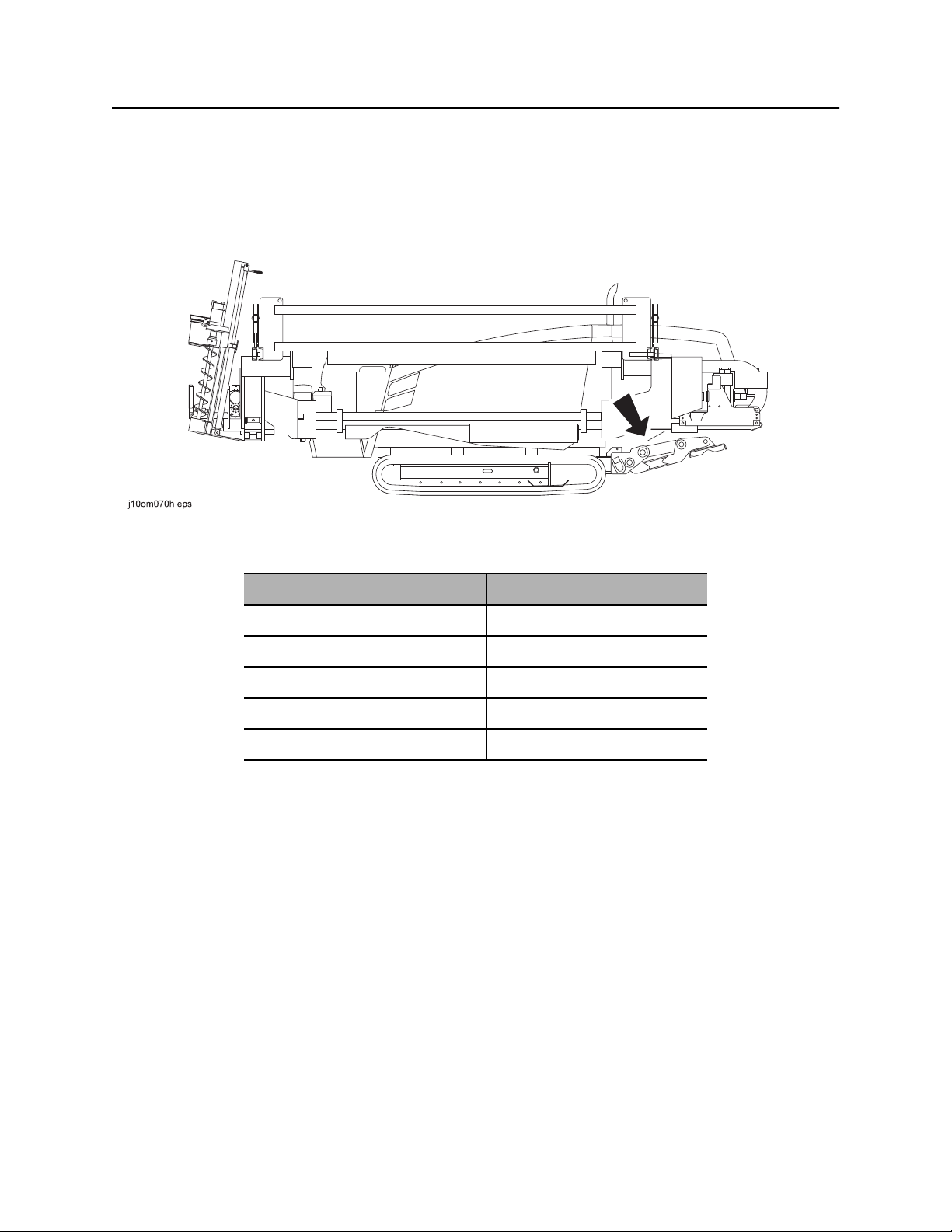
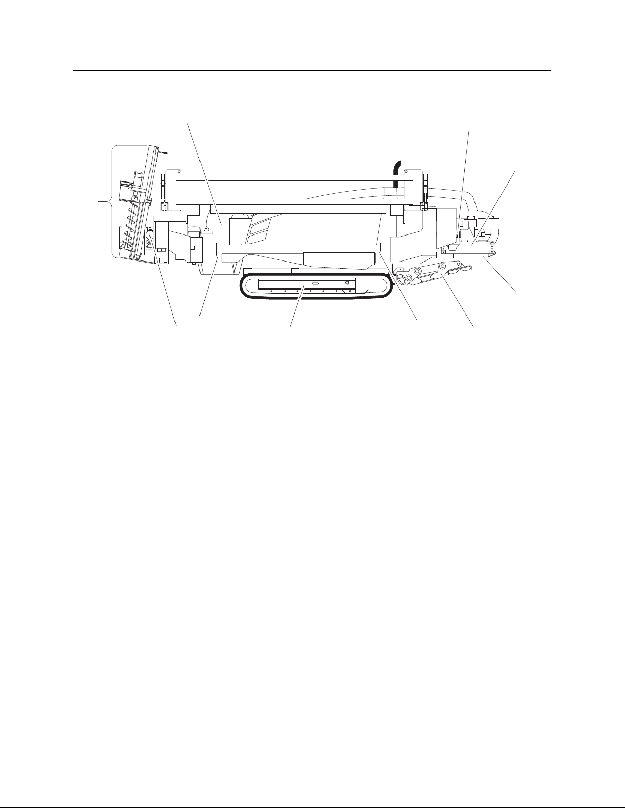
Unit Components
Unit Components
9
j10om001h.eps
1. Operator’s station
2. Spindle
1
2
3
4
6
78
6. Pipeloader
7. Tracks
6
5
3. Carriage
4. Drill frame
5. Stabilizer
8. Vise wrenches
9. Anchoring system
CMW
JT2020 Mach 1 Operator’s Manual Overview - 5
Operator Orientation
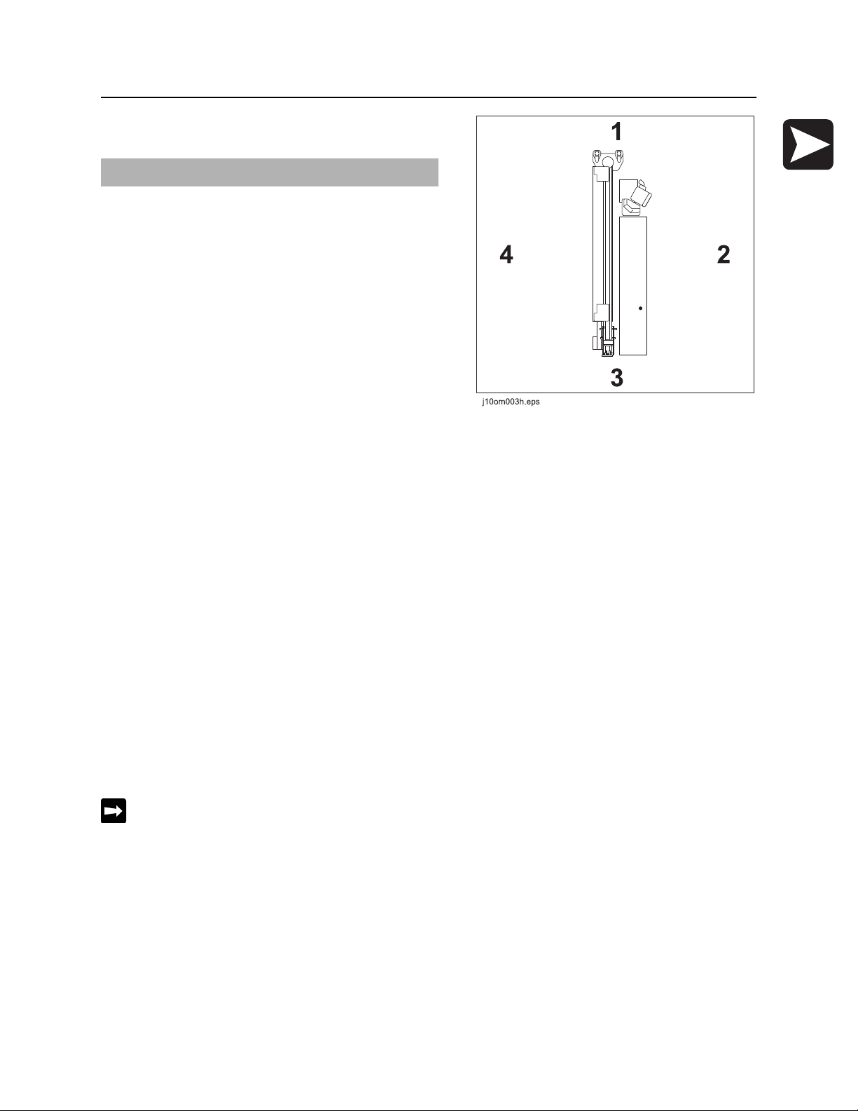
Operator Orientation
IMPORTANT: Top view of unit is shown.
1. Front of unit
2. Right side of unit
3. Rear of unit
4. Left side of unit
About This Manual
This manual contains information for the proper use of this machine. See the beige Operation Overview
pages for basic operating procedures. Cross references such as “See page 50” will direct you to detailed
procedures.
Bulleted Lists
Bulleted lists provide helpful or important information or contain procedures that do not have to be
performed in a specific order.
Numbered Lists
Numbered lists contain illustration callouts or list steps that must be performed in order.
“Continued” Indicators
indicates that a procedure is continued on the next page.
CMW

Overview - 6 JT2020 Mach 1 Operator’s Manual
About This Manual
CMW

JT2020 Mach 1 Operator’s Manual Foreword - 7
Foreword
This manual is an important part of your equipment. It provides safety information and operation
instructions to help you use and maintain your Ditch Witch equipment.
Read this manual before using your equipment. Keep it with the equipment at all times for future reference.
If you sell your equipment, be sure to give this manual to the new owner.
If you need a replacement copy, contact your Ditch Witch dealer. If you need assistance in locating a
dealer, visit our website at www.ditchwitch.com or write to the following address:
The Charles Machine Works, Inc.
Attn: Marketing Department
PO Box 66
Perry, OK 73077-0066
USA
The descriptions and specifications in this manual are subject to change without notice. The Charles
Machine Works, Inc. reserves the right to improve equipment. Some product improvements may have
taken place after this manual was published. For the latest information on Ditch Witch equipment, see your
Ditch Witch dealer.
Thank you for buying and using Ditch Witch equipment.
CMW

Foreword - 8 JT2020 Mach 1 Operator’s Manual
JT2020 Mach 1 (Tier 3)
Operator’s Manual
Issue number 3.0/OM-4/11
Part number 053-1361
Copyright 2009, 2010, 2011
by The Charles Machine Works, Inc.
, Ditch Witch, CMW, AutoCrowd, Jet Trac, Roto Witch, Subsite, Fluid Miser,
Power Pipe, Super Witch, Pierce Airrow, The Underground, The Underground Authority Worldwide, and
Zahn are registered trademarks of The Charles Machine Works, Inc.
This product is covered by one or more of the following patents:
U.S. B1 4,858,704; 4,953,638; 5,148,880; 5,242,026; 5,341,887; 5,490,569; 5,684,466; 5,713,423; 5,794,719; 5,880,680; 5,941,322;
6,085,852; 6,109,371; 6,179,065; 6,216,803; 6,250,403; 6,250,404; 6,290,606; 6,311,790; 6,411,094; 6,543,551; 6,550,547;
6,672,409; 6,739,413; 6,761,231; 6,776,246; 6,808,210; 6,827,158; 6,848,506; 6,871,712; RE37,450; RE37,923; RE37,975;
RE38,418; AU 689,533; 706,544; 718,034; 755,862; CA 2,156,398; 2,217,899; DE 694 17 019; 695 29 634; 297 01 406;
EP 0683845; 0674093; 0817901; 0846841; 0927892; FR 674,093; GB 2,309,239; 2,312,006; EP674,093; EP846,841; JP 3,458,247;
other U.S. and foreign patents pending.
CMW
JT2020 Mach 1 Operator’s Manual Contents - 9
Contents
Overview
machine serial number, information about the type of work this machine is designed
to perform, basic machine components, and how to use this manual
Foreword
part number, revision level, and publication date of this manual, and factory contact
information
Safety
machine safety alerts and emergency procedures
Controls
machine controls, gauges, and indicators and how to use them
Operation Overview
an overview for completing a job with this machine: planning, setting up, installing
product, and restoring the jobsite; with cross references to detailed procedures
Prepare
procedures for inspecting and classifying the jobsite, planning the installation path,
and preparing the jobsite for work
Drive
procedures for startup, cold start, driving, and shutdown
1
7
11
21
59
63
79
Transport
procedures for lifting, hauling, and towing
Conduct a Bore
procedures for drilling and backreaming
Systems and Equipment
downhole tools and drill pipe, anchor, electric strike, tracker control, and fluid
systems
Complete the Job
procedures for restoring the jobsite and rinsing and storing equipment
Service
service intervals and instructions for this machine including lubrication, replacement
of wear items, and basic maintenance
83
91
113
153
159
CMW

Contents - 10 JT2020 Mach 1 Operator’s Manual
Specifications
machine specifications including weights, measurements, power ratings, and fluid
capacities
Support
the warranty policy for this machine, and procedures for obtaining warranty
consideration and training
Service Record
a record of major service performed on the machine
193
153
201
CMW

JT2020 Mach 1 Operator’s Manual Safety - 11
Safety
Chapter Contents
Guidelines . . . . . . . . . . . . . . . . . . . . . . . . . . . . . . . . 12
Safety Alert Classifications . . . . . . . . . . . . . . . . . . 13
Safety Alerts . . . . . . . . . . . . . . . . . . . . . . . . . . . . . . 14
Emergency Procedures . . . . . . . . . . . . . . . . . . . . . 17
• Electric Strike Description. . . . . . . . . . . . . . . . . . . . . . . . . . . . . . . . . . . 17
• If an Electric Line is Damaged . . . . . . . . . . . . . . . . . . . . . . . . . . . . . . . 18
• If a Gas Line is Damaged . . . . . . . . . . . . . . . . . . . . . . . . . . . . . . . . . . . 19
• If a Fiber Optic Cable is Damaged . . . . . . . . . . . . . . . . . . . . . . . . . . . . 20
• If Machine Catches on Fire. . . . . . . . . . . . . . . . . . . . . . . . . . . . . . . . . . 20
CMW

Safety - 12 JT2020 Mach 1 Operator’s Manual
Guidelines
Guidelines
Follow these guidelines before operating any jobsite equipment:
• Complete proper training and read operator’s manual before using equipment.
• Contact your local One-Call (811 in USA) or the One-Call referral number (888-258-0808 in USA and
Canada) to have underground utilities located before digging. Also contact any utilities that do not
participate in the One-Call service.
• Classify jobsite based on its hazards and use correct tools and machinery, safety equipment, and work
methods for jobsite.
• Mark jobsite clearly and keep spectators away.
• Wear personal protective equipment.
• Review jobsite hazards, safety and emergency procedures, and individual responsibilities with all
personnel before work begins. Safety videos are available from your Ditch Witch dealer.
• Replace missing or damaged safety shields and safety signs.
• Use equipment carefully. Stop operation and investigate anything that does not look or feel right.
• Do not operate unit where flammable gas may be present.
• Contact your Ditch Witch dealer if you have any question about operation, maintenance, or equipment
use.
CMW

JT2020 Mach 1 Operator’s Manual Safety - 13
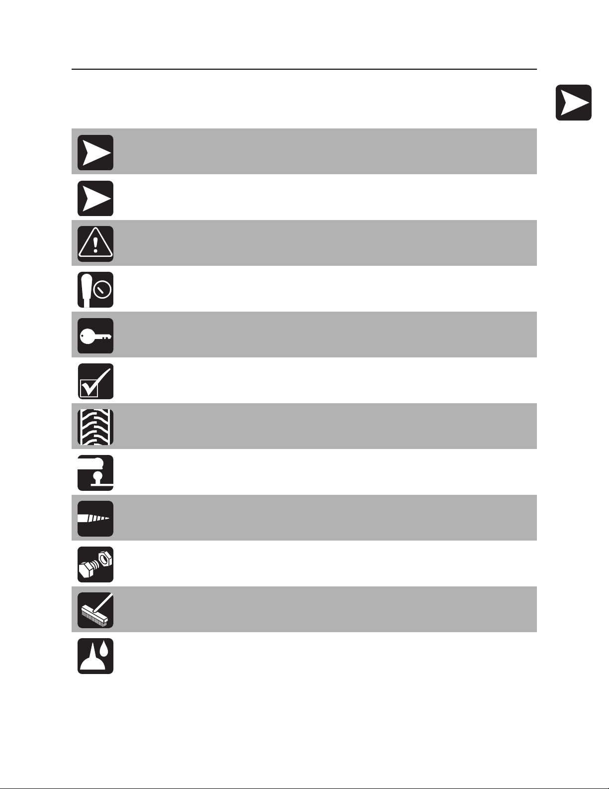
Safety Alert Classifications
Safety Alert Classifications
These classifications and the icons defined on the following pages work together to alert you to situations
which could be harmful to you, jobsite bystanders or your equipment. When you see these words and
icons in the book or on the machine, carefully read and follow all instructions. YOUR SAFETY IS AT
STAKE.
Watch for the three safety alert levels: DANGER, WARNING and CAUTION. Learn what each level
means.
indicates an imminently hazardous situation which, if not avoided, will result in death or
serious injury.
indicates a potentially hazardous situation which, if not avoided, could result in death or
serious injury.
indicates a potentially hazardous situation which, if not avoided, may result in minor or
moderate injury.
Watch for two other words: NOTICE and IMPORTANT.
NOTICE can keep you from doing something that might damage the machine or someone's property. It
can also alert you against unsafe practices.
IMPORTANT can help you do a better job or make your job easier in some way.
CMW
Safety - 14 JT2020 Mach 1 Operator’s Manual
Safety Alerts
Safety Alerts
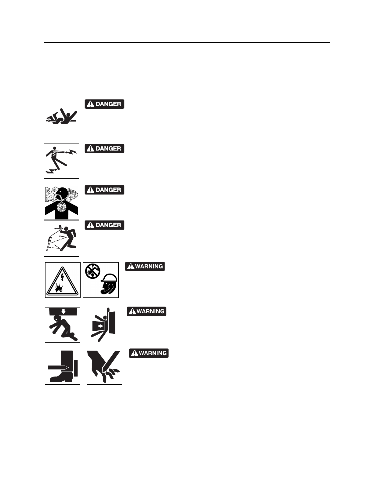
Turning shaft will kill you or crush arm or leg. Stay away.
Electric shock. Contacting electric lines will cause death or serious injury.
Know location of lines and stay away.
Deadly gases. Lack of oxygen or presence of gas will cause sickness or
death. Provide ventilation.
Moving tools will kill or injure. Shut off drill string power when anyone can be
struck by moving or thrown tools. Never use pipe wrenches on drill string.
Jobsite hazards could cause death or serious injury. Use
correct equipment and work methods. Use and maintain proper safety
equipment.
Crushing weight could cause death or serious injury. Use
proper procedures and equipment or stay away.
Moving parts could cut off hand or foot. Stay away.
CMW
JT2020 Mach 1 Operator’s Manual Safety - 15
Safety Alerts
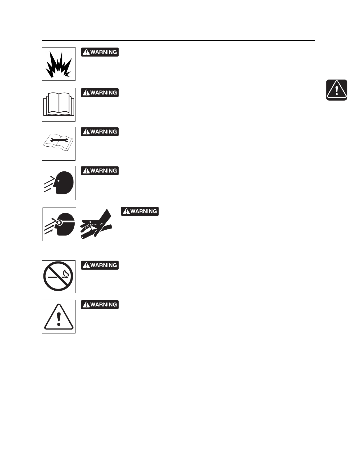
Explosion possible. Serious injury or equipment damage could occur.
Follow directions carefully.
Incorrect procedures could result in death, injury, or property damage.
Learn to use equipment correctly.
Improper control function could cause death or serious injury. If control does
not work as described in instructions, stop machine and have it serviced.
Looking into fiber optic cable could result in permanent vision damage. Do
not look into ends of fiber optic or unidentified cable.
Pressurized fluid or air could pierce skin and cause injury or
death. Stay away.
Fire or explosion possible. Fumes could ignite and cause burns. No
smoking, no flame, no spark.
Moving traffic - hazardous situation. Death or serious injury could result.
Avoid moving vehicles, wear high visibility clothing, post appropriate warning signs.
CMW
Safety - 16 JT2020 Mach 1 Operator’s Manual
Safety Alerts
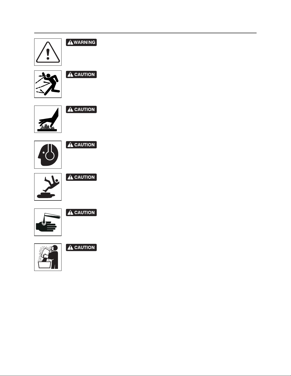
Hot pressurized cooling system fluid could cause serious burns. Allow to
cool before servicing.
Flying objects may cause injury. Wear hard hat and safety glasses.
Hot parts may cause burns. Do not touch until cool.
Exposure to high noise levels may cause hearing loss. Wear hearing
protection.
Fall possible. Slips or trips may result in injury. Keep area clean.
Battery acid may cause burns. Avoid contact.
Improper handling or use of chemicals may result in illness, injury, or
equipment damage. Follow instructions on labels and in material safety data sheets
(MSDS).
CMW
JT2020 Mach 1 Operator’s Manual Safety - 17
Emergency Procedures
Emergency Procedures
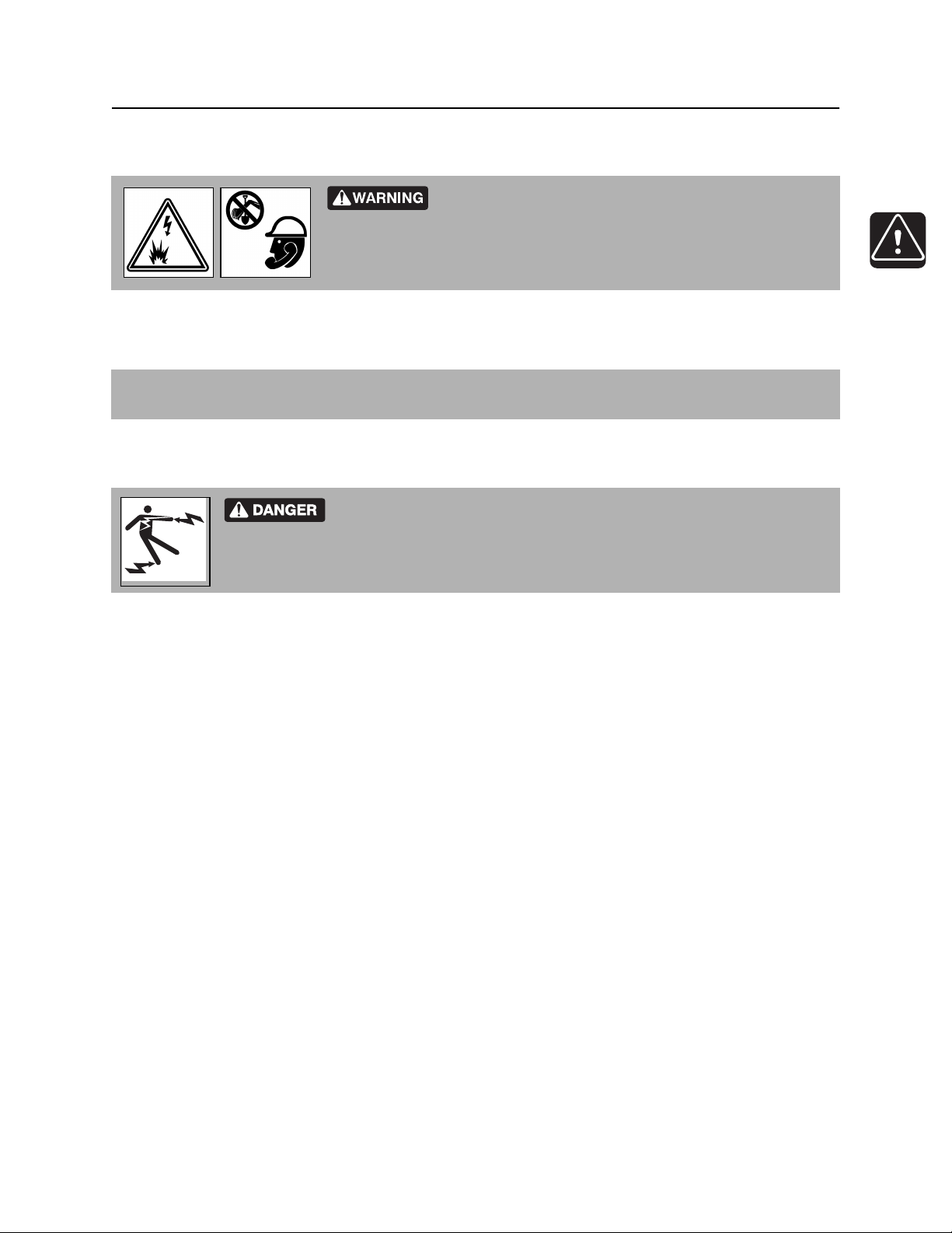
Jobsite hazards could cause death or serious injury. Use
correct equipment and work methods. Use and maintain proper safety
equipment.
Before operating any equipment, review emergency procedures and check that all safety precautions have
been taken.
EMERGENCY SHUTDOWN - Turn ignition switch to stop position or push remote engine stop button (if
equipped).
Electric Strike Description
Electric shock. Contacting electric lines will cause death or serious injury.
Know location of lines and stay away.
When working near electric cables, remember the following:
• Electricity follows all paths to ground, not just path of least resistance.
• Pipes, hoses, and cables will conduct electricity back to all equipment.
• Low voltage current can injure or kill. Many work-related electrocutions result from contact with less
than 440 volts.
Most electric strikes are not noticeable, but indications of a strike include:
• power outage
• smoke
• explosion
• popping noises
• arcing electricity
If any of these occur, or if strike alarm sounds or flashes, assume an electric strike has occurred.
CMW

Safety - 18 JT2020 Mach 1 Operator’s Manual
Emergency Procedures
If an Electric Line is Damaged
If you suspect an electric line has been damaged and you are on drilling unit or bonded equipment, DO
NOT MOVE. Remain on drilling machine or mats and take the following actions. The order and degree of
action will depend on the situation.
• Warn people nearby that an electric strike has occurred.
• Have someone contact electric company.
• Reverse drilling direction and try to break contact. Do not touch drill pipe with hands or hand-held
tools.
• Press electric strike system status button.
• If alarm sounds again, stay where you are and wait for electric company to shut off power.
• If alarm does not sound and there is no other indication of a strike, wait at least one full minute
before moving away from equipment. Utility might use automatic reclosers which will restart
current flow. If alarm sounds again while waiting, stay where you are until electric company shuts
off power.
• If alarm does not sound but all lights in strike indicator are on, assume strike is continuing and stay
where you are until electric company shuts off power.
• Do not resume drilling or allow anyone into area until given permission by electric company.
If you suspect an electric line has been damaged and you are off drilling unit or bonded equipment, DO
NOT TOUCH ANY EQUIPMENT connected to drilling unit. Take the following actions. The order and
degree of action will depend on the situation.
• Stay where you are unless you are wearing electric insulating boots. If you leave, do not return to area
or allow anyone into area until given permission by electric company.
CMW
JT2020 Mach 1 Operator’s Manual Safety - 19
Emergency Procedures
If a Gas Line is Damaged
Fire or explosion possible. Fumes could ignite and cause burns. No
smoking, no flame, no spark.
Explosion possible. Serious injury or equipment damage could occur.
Follow directions carefully.
If you suspect a gas line has been damaged, take the following actions. The order and degree of action will
depend on the situation.
• Immediately shut off engine(s), if this can be done safely and quickly.
• Remove any ignition source(s), if this can be done safely and quickly.
• Warn others that a gas line has been cut and that they should leave the area.
• Leave jobsite as quickly as possible.
• Immediately call your local emergency phone number and utility company.
• If jobsite is along street, stop traffic from driving near jobsite.
• Do not return to jobsite until given permission by emergency personnel and utility company.
CMW

Safety - 20 JT2020 Mach 1 Operator’s Manual
Emergency Procedures
If a Fiber Optic Cable is Damaged
Do not look into cut ends of fiber optic or unidentified cable. Vision damage can occur.
If Machine Catches on Fire
Perform emergency shutdown procedure and then take the following actions. The order and degree of
action will depend on the situation.
• Immediately move battery disconnect switch (if equipped) to disconnect position.
• If fire is small and fire extinguisher is available, attempt to extinguish fire.
• If fire cannot be extinguished, leave area as quickly as possible and contact emergency personnel.
CMW

JT2020 Mach 1 Operator’s Manual Controls - 21
Controls
Chapter Contents
Set-Up Console . . . . . . . . . . . . . . . . . . . . . . . . . . . 22
Tethered Ground Drive Controller . . . . . . . . . . . . 25
Left Control Console . . . . . . . . . . . . . . . . . . . . . . . 27
• Pipeloading controls . . . . . . . . . . . . . . . . . . . . . . . . . . . . . . . . . . . . . . . 27
• Drilling/Operation controls . . . . . . . . . . . . . . . . . . . . . . . . . . . . . . . . . . 31
Gauge Cluster . . . . . . . . . . . . . . . . . . . . . . . . . . . . 34
• Unit status indicators . . . . . . . . . . . . . . . . . . . . . . . . . . . . . . . . . . . . . . 34
• Pipeloading status indicators . . . . . . . . . . . . . . . . . . . . . . . . . . . . . . . . 37
• Gauges . . . . . . . . . . . . . . . . . . . . . . . . . . . . . . . . . . . . . . . . . . . . . . . . . 40
Right Control Console . . . . . . . . . . . . . . . . . . . . . . 42
Anchoring System Console . . . . . . . . . . . . . . . . . 44
Seat/Armrest . . . . . . . . . . . . . . . . . . . . . . . . . . . . . . 46
Battery . . . . . . . . . . . . . . . . . . . . . . . . . . . . . . . . . . . 48
ESID . . . . . . . . . . . . . . . . . . . . . . . . . . . . . . . . . . . . . 49
Ditch Witch Electronics 750/752 Display . . . . . . . 53
• Indicators . . . . . . . . . . . . . . . . . . . . . . . . . . . . . . . . . . . . . . . . . . . . . . . 53
• Controls . . . . . . . . . . . . . . . . . . . . . . . . . . . . . . . . . . . . . . . . . . . . . . . . 56
CMW
Controls - 22 JT2020 Mach 1 Operator’s Manual
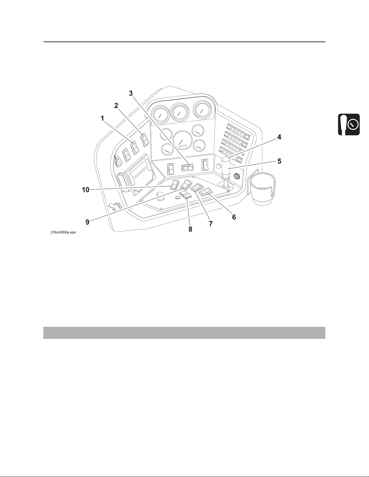
Set-Up Console
Set-Up Console
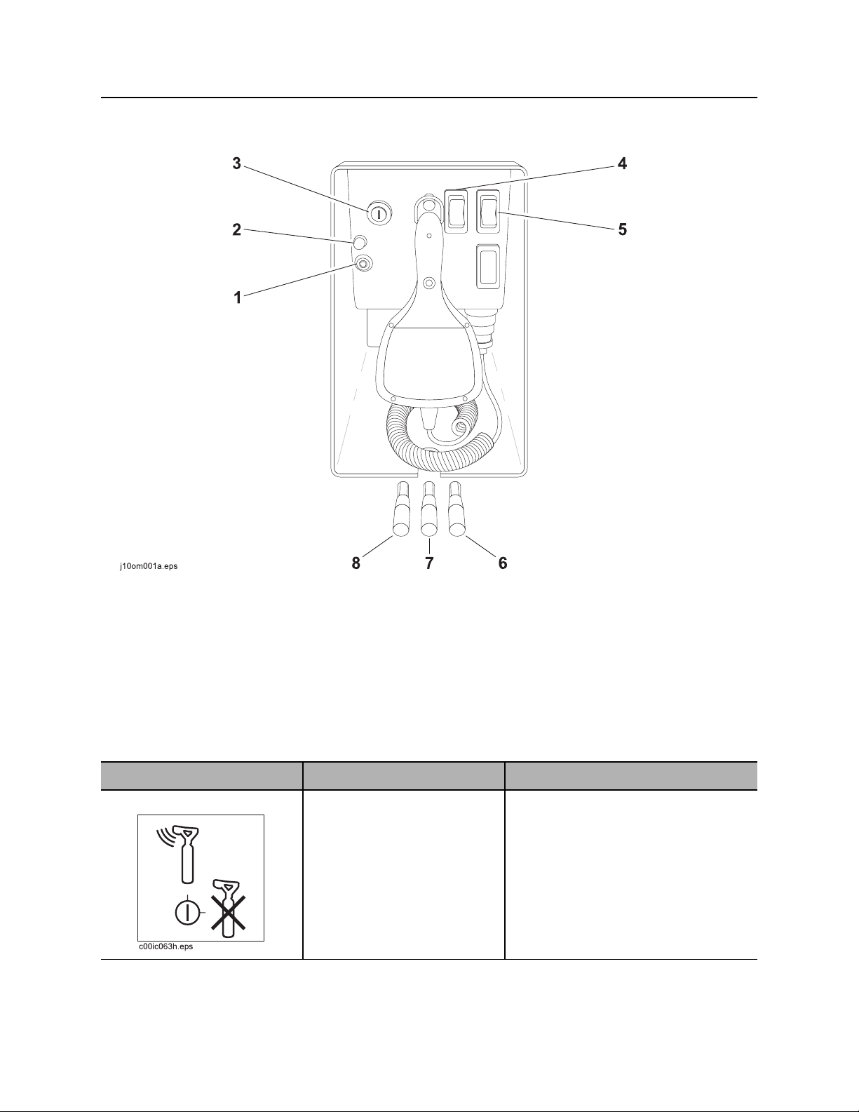
1. Tracker control key
2. Cold start wait indicator
3. Ignition switch
4. Left track switch
Item Description Notes
1. Tracker control key To allow tracker operator to
stop thrust and rotation, move
key to enable position (up).
To override tracker control
mode, move key to disable
position (right).
5. Right track switch
6. Right stabilizer control
7. Frame tilt control
8. Left stabilizer control
IMPORTANT: Remove key and keep
in tracker operator’s possession.
CMW
JT2020 Mach 1 Operator’s Manual Controls - 23
Set-Up Console
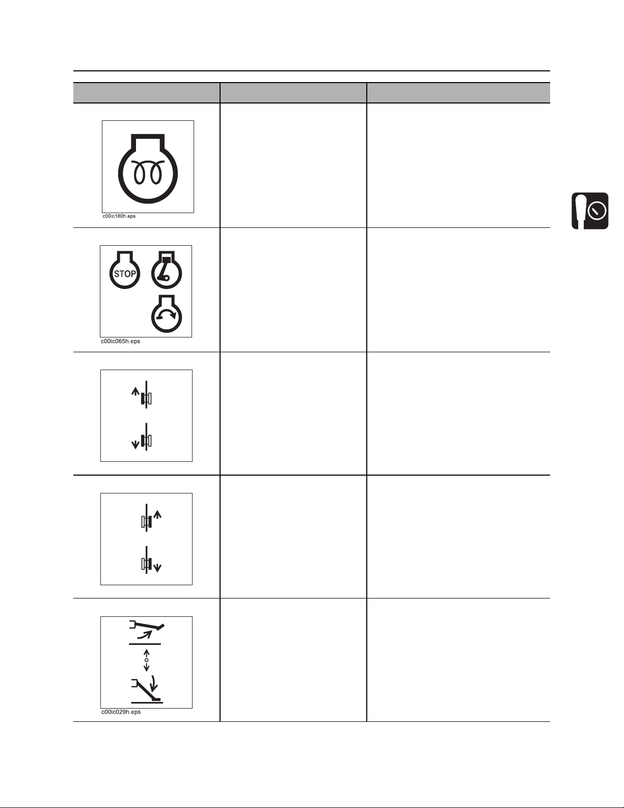
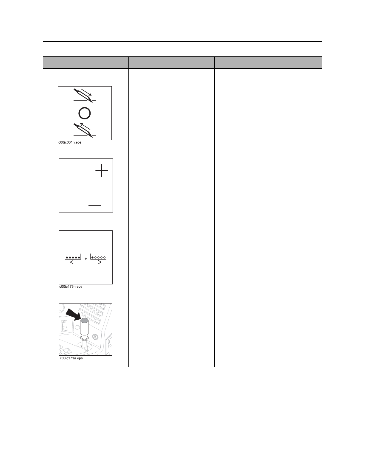
Item Description Notes
2. Cold start wait indicator Lights when intake air pre-
heater is operating.
Wait until light goes off before
starting engine.
3. Ignition switch To start engine, insert key and
turn clockwise.
To stop engine, turn key
counterclockwise.
4. Left track switch To move forward, press top.
To move backward, press
bottom.
c00ic147h.eps
5. Right track switch To move forward, press top.
To move backward, press
bottom.
IMPORTANT:
• Restart engine with ignition switch
after it has been turned off with
remote engine stop switch.
• If wrenches are engaged when
engine is stopped with ignition
switch, wrenches will release and
then engage when unit is started.
IMPORTANT: Use track switches only
if tethered control is inoperable.
IMPORTANT: Use track switches only
if tethered control is inoperable.
c00ic148h.eps
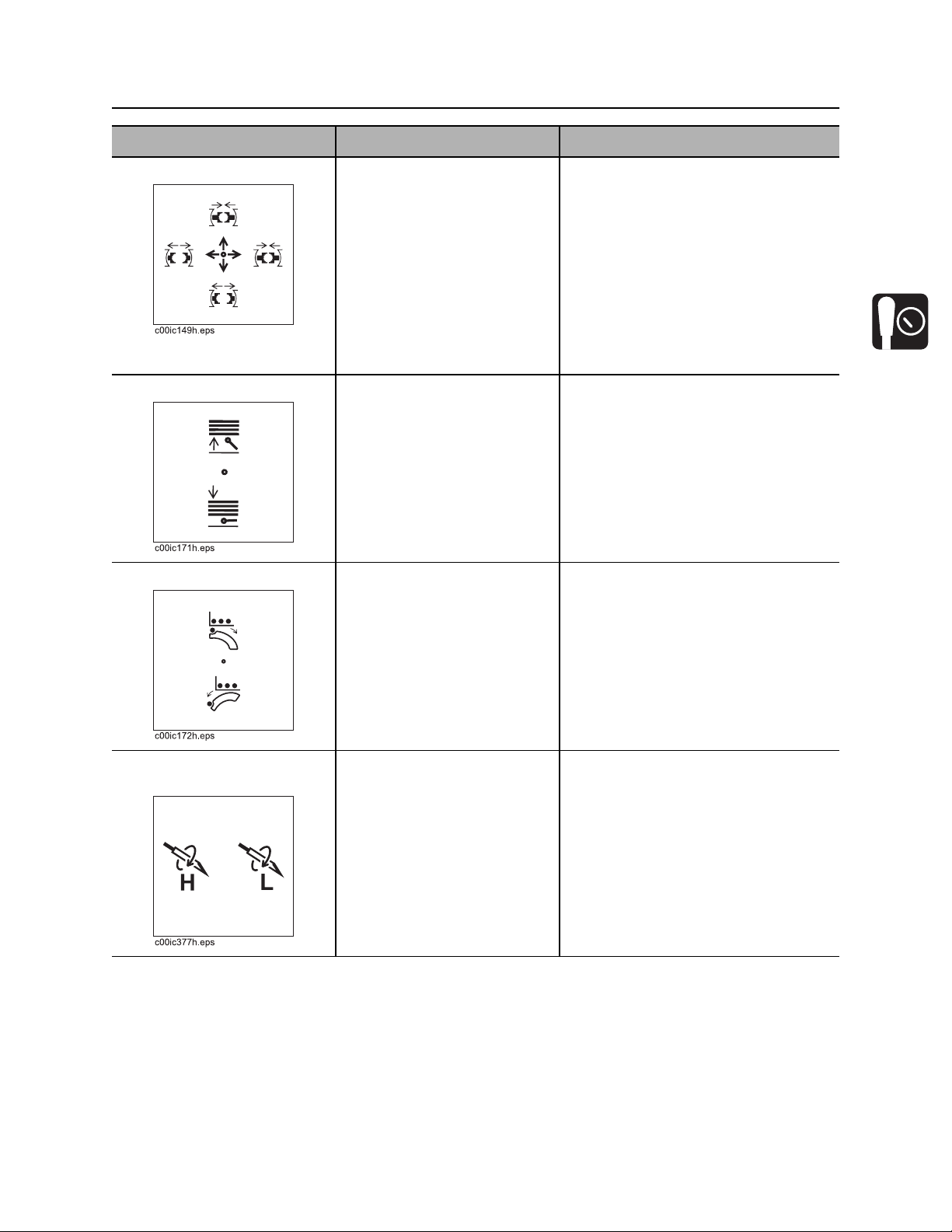
6. Right stabilizer control To raise, pull up.
To lower, push down.
IMPORTANT: Lower left and right
stabilizers to the ground to stabilize
unit and then adjust for side-to-side
stability. After unit is level, adjust for
entry angle.
NOTICE: Stand clear of stabilizer to
avoid crushing your foot.
CMW
Controls - 24 JT2020 Mach 1 Operator’s Manual
Set-Up Console
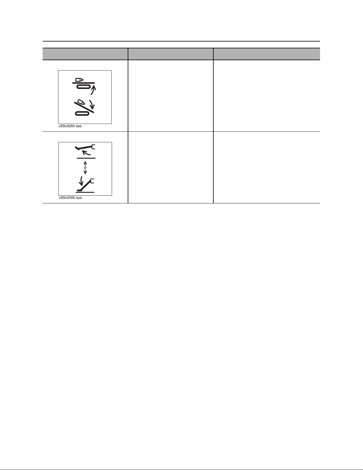
Item Description Notes
7. Frame tilt control To raise front end of drill
frame, pull up.
To lower front end of drill
frame, push down.
8. Left stabilizer control To raise, pull up.
To lower, push down.
IMPORTANT: Lower left and right
stabilizers to the ground to stabilize
unit and then adjust for side-to-side
stability. After unit is level, adjust for
entry angle.
NOTICE: Stand clear of stabilizer to
avoid crushing your foot.
CMW
JT2020 Mach 1 Operator’s Manual Controls - 25
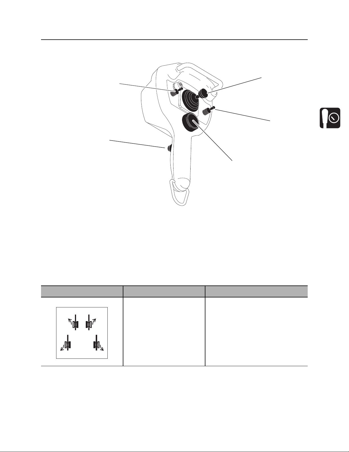
Tethered Ground Drive Controller
Tethered Ground Drive Controller
1
5
2
4
3
j10om016h.eps
1. Speed/direction control
2. Power mode switch
3. Remote engine stop
Item Description Notes
1. Speed/direction control To move forward, push.
To move backward, pull.
To steer, move left or right.
c00ic145h.eps
4. Operator presence switch
5. Throttle switch
IMPORTANT:
• Operator presence switch must
• See “Steer Unit” on page 80 for
be pressed and operator seat
must be empty for control to work.
more information.
CMW
Controls - 26 JT2020 Mach 1 Operator’s Manual
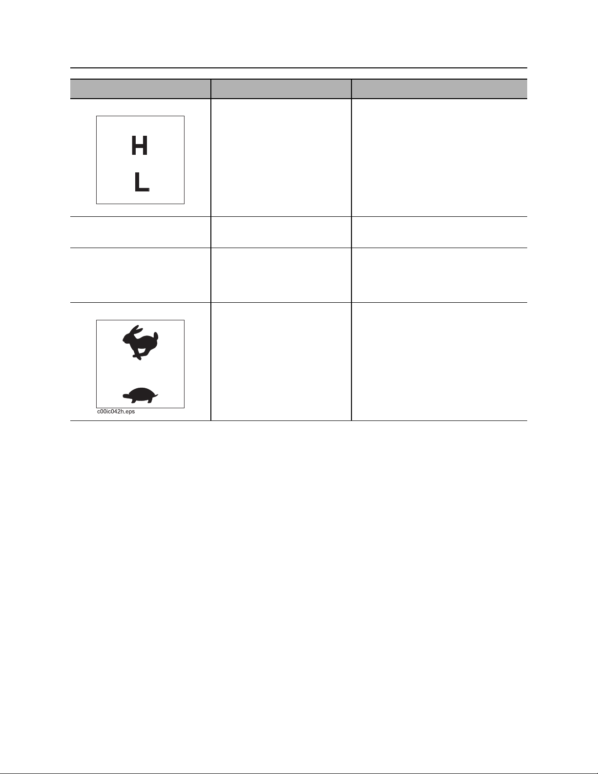
Tethered Ground Drive Controller
Item Description Notes
2. Power mode switch To select normal driving mode
(high), push.
To select loading and
unloading mode (low), pull.
To disable controller, return to
center.
c00ic146h.eps
3. Remote engine stop To stop engine, press red
button.
4. Operator presence
switch
To operate ground drive with
tethered controller, press.
To disable controller, release.
5. Throttle switch To increase engine speed,
push.
To decrease engine speed,
pull.
IMPORTANT: To restart engine, turn
ignition switch off and then back on.
IMPORTANT: Throttle switch at
operator’s station must be in center
position for this switch to control
speed.
CMW
JT2020 Mach 1 Operator’s Manual Controls - 27
Left Control Console
Left Control Console
Pipeloading Controls
1. Add pipe/manual/remove pipe switch
2. Set/Resume switch
3. Pipe box switch
4. Resume switch
5. Wrench control
IMPORTANT: Switch 1 will not function unless unit is equipped with pipeloader automation option.
6. Pipe lift switch
7. Pipe shuttle switch
8. Two-speed rotation switch
9. Pipe gripper switch
10. Pipe lubricator switch
CMW
Controls - 28 JT2020 Mach 1 Operator’s Manual
Left Control Console
Item Description Notes
1. Add pipe/manual/
remove pipe switch
To select “add pipe”
automated pipeloader
function, press top.
To use manual pipeloader
controls, move to center.
To select “remove pipe”
automated pipeloader
function, press bottom.
2. Set/Resume switch To resume operation or
increase operation levels,
RESUME /
press top.
To set operating conditions or
reduce operation levels,
press bottom.
SET /
c00ic113h.eps
3. Pipe box switch To shift pipe box toward
operator, press left side.
To shift pipe box away from
operator, press right side.
See “Add Pipe” on page 102.
See “Remove Pipe” on page 109.
See “Cruise Control” on page 146.
IMPORTANT: See “Shift Pipe Box” on
page 141.
4. Resume switch To resume operation, press. See “Add Pipe” on page 102.
CMW
JT2020 Mach 1 Operator’s Manual Controls - 29
Left Control Console
Item Description Notes
5. Wrench control To clamp front wrench, move
to right.
To unclamp front wrench,
move to left.
To clamp and rotate rear
(rotating) wrench, push.
To unclamp rear (rotating)
wrench, pull.
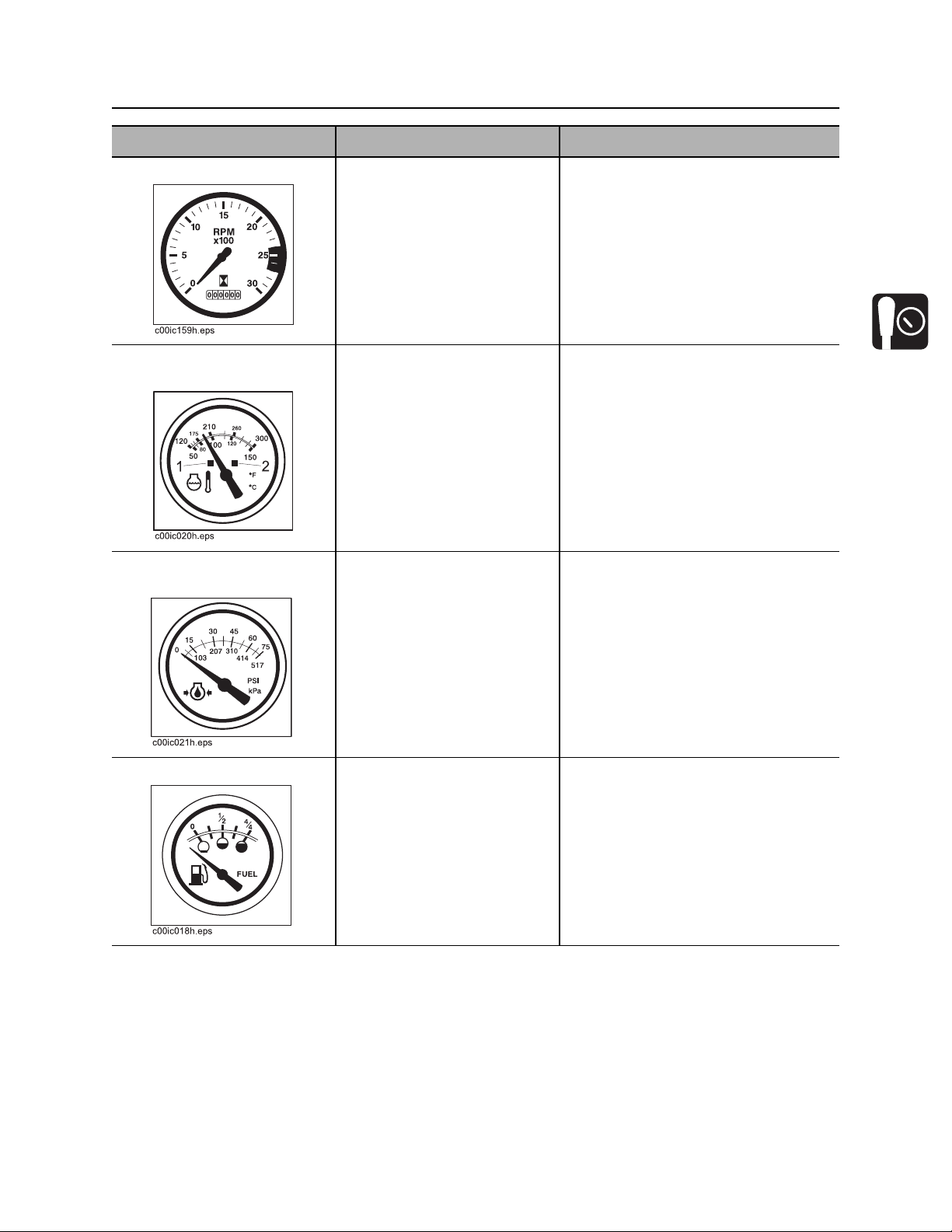
6. Pipe lift switch To raise, press top.
To lower, press bottom.
7. Pipe shuttle switch To move toward pipe box,
press top.
To move toward spindle,
press bottom.
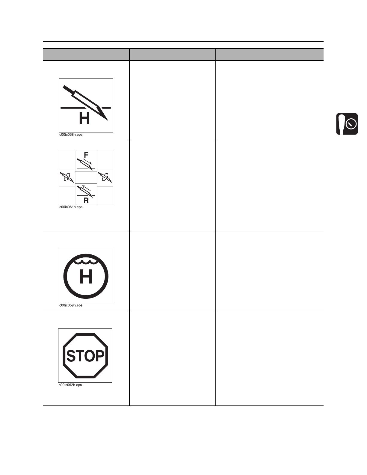
8. Two-speed rotation
switch
To rotate at low speed, high
torque, press right.
To rotate at high speed, low
torque, press left.
CMW

Controls - 30 JT2020 Mach 1 Operator’s Manual
Left Control Console
Item Description Notes
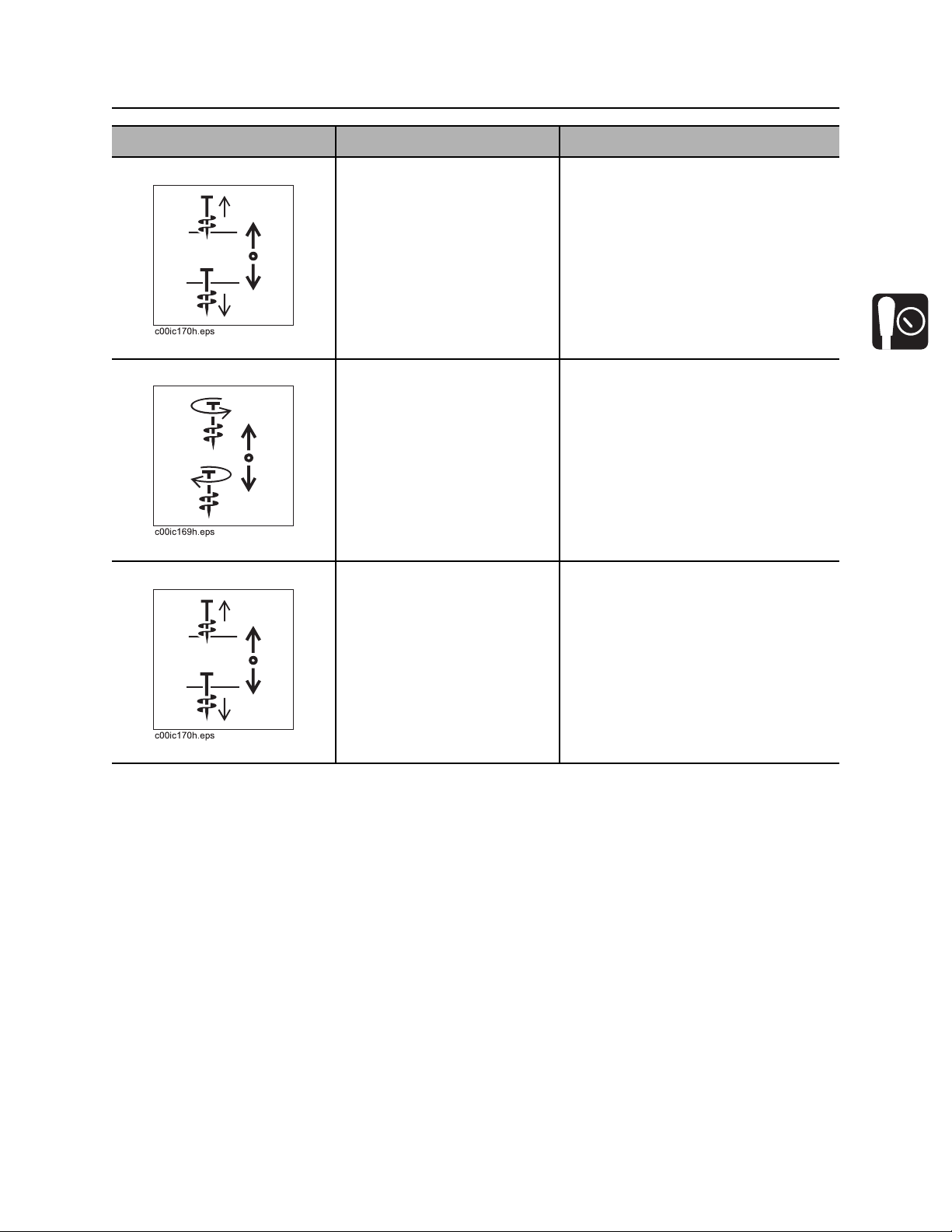
9. Pipe gripper switch To close, press top.
To open, press bottom.
10. Pipe lubricator switch To fill applicator at back of
pipeloader, press top.
To apply joint compound to
threads at wrenches, press
bottom.
c00ic150h.eps
CMW

JT2020 Mach 1 Operator’s Manual Controls - 31
Left Control Console
Drilling/Operation Controls
1. Engine throttle switch
2. Drilling fluid pressure gauge
3. Thrust pressure gauge
4. Rotation pressure gauge
5. Remote engine start switch
Item Description Notes
1. Engine throttle switch To increase speed, press top.
Return switch to center when
desired speed is reached.
To enable autothrottle mode,
press top and leave switch in
top position.
To decrease speed, press
bottom.
To disable autothrottle mode,
return switch to center after
desired speed is reached.
6. Console/Work light switch
7. Fluid pump speed switch
8. Fluid pump indicator
9. Fluid flow control
Autothrottle mode slows the engine to
low throttle after 15 seconds of
inactivity involving thrust, rotation,
drilling fluid flow, or pipeloader
functions. To return to high speed,
activate thrust, rotation, drilling fluid,
or an add/remove cycle.
CMW

Controls - 32 JT2020 Mach 1 Operator’s Manual
Left Control Console
Item Description Notes
2. Drilling fluid pressure
gauge
Displays drilling fluid pressure
supplied by drilling fluid
pump.
c00ic157h.eps
3. Thrust pressure gauge Displays hydraulic fluid
pressure to thrust motor
during thrust and pullback.
Estimates thrust and pullback
force on lines outside gauge.
4. Rotation pressure
gauge
Displays hydraulic fluid
pressure to rotation motor
when spindle is turned
clockwise.
5. Remote engine start
switch
c00ic152h.eps
Estimates rotational torque on
lines outside gauge.
To start engine from
operator’s station, push
button.
Release when engine starts.
IMPORTANT: This button works only
when key on set-up console is on,
operator is in seat, and battery
disconnect switch is closed.
CMW

JT2020 Mach 1 Operator’s Manual Controls - 33
Left Control Console
Item Description Notes
6. Console/Work light
switch
c00ic151h.eps
7. Fluid pump speed
switch
8. Fluid pump indicator If fluid pump is on, light
To turn on, press top.
To turn off, press bottom.
For high speed, press top.
For low speed, press bottom.
should be on.
High speed delivers more flow at
lower pressure.
Low speed delivers less flow at higher
pressure.
If fluid pump is off, light
should be off.
9. Fluid flow control To increase flow, turn
clockwise.
To decrease flow, turn
counterclockwise.
To stop flow, turn all the way
counterclockwise.
CMW

Controls - 34 JT2020 Mach 1 Operator’s Manual
Gauge Cluster
Gauge Cluster
Unit Status Indicators
1. Diagnostic light (red)
2. Hydraulic fluid temperature indicator
3. Hydraulic filter service indicator
4. Fluid pump status indicator
5. Operator presence indicator
6. Cold start wait indicator
7. Water in fuel indicator
8. Battery charging indicator
CMW

JT2020 Mach 1 Operator’s Manual Controls - 35
Gauge Cluster
Item Description Notes
1. Diagnostic light (red) If system is OK, light should
be off.
If system may not be getting
power, light should be on.
2. Hydraulic fluid
temperature indicator
3. Hydraulic filter service
indicator
If a non-essential diagnostic
code is recorded, light should
flash on and off for 10
seconds.
If an essential diagnostic
code is recorded, light should
flash on for three seconds
and off for half a second.
Indicates hydraulic fluid is
overheating.
Indicates hydraulic fluid filter
needs replacing.
See “Interpret Diagnostic Codes” on
page 147.
• Check hydraulic fluid level.
• Check cooler for debris. See
page 174.
Change filter when indicator lights
continuously and as indicated on
page 174.
4. Fluid pump status
indicator
If fluid pump is on, light
should be on.
If fluid pump is off, light
should be off.
NOTICE: Do not run fluid pump
without fluid.
CMW

Controls - 36 JT2020 Mach 1 Operator’s Manual
Gauge Cluster
Item Description Notes
5. Operator presence
indicator
6. Cold start wait indicator Lights when intake air pre-
7. Water in fuel indicator Indicates the presence of
Indicates operator is seated
in operator’s station.
heater is operating.
Wait until light goes off before
starting engine.
water in the fuel.
Thrust and rotation will not operate
unless light is on.
Drain water from fuel filter. See
page 165.
8. Battery charging
indicator
CMW
Indicates battery is not
charging.

JT2020 Mach 1 Operator’s Manual Controls - 37
Gauge Cluster
Pipeloading Status Indicators
1. Control cycle light (green)
2. Front wrench status indicator
3. Shuttle home status indicator
4. Carriage home status indicator
Item Description Notes
1. Control cycle light
(green)
If nothing is being controlled,
light should be off.
If system is waiting for an
action before starting cycle,
light should flash on and off.
If something is being
controlled, light should be on.
If control cycle is interrupted,
light should flash twice
quickly.
5. Rear stop status indicator
6. Pipe lift status indicator
7. Front pipe box status indicator
8. Rear pipe box status indicator
CMW

Controls - 38 JT2020 Mach 1 Operator’s Manual
Gauge Cluster
Item Description Notes
2. Front wrench status
indicator
3. Shuttle home status
indicator
4. Carriage home status
indicator
If front wrench is closed, light
should be on.
If front wrench is open, light
should be off.
If shuttle is retracted, light
should be on.
If shuttle is not completely
retracted, light should be off.
If carriage is in the home
zone at either end of drill
frame, light should be on.
5. Rear stop status
indicator
If carriage is out of the home
zone at either end of drill
frame, light should be off.
If carriage is at very back of
drill frame, light should be on.
If carriage is away from very
back of drill frame, light
should be off.
CMW

JT2020 Mach 1 Operator’s Manual Controls - 39
Gauge Cluster
Item Description Notes
6. Pipe lift status indicator If pipe lifter is lifted fully and
lift pressure switch is
engaged, light should be on.
If pipe lift pressure switch is
not engaged, light should be
off.
7. Front pipe box status
indicator
8. Rear pipe box status
indicator
If active pipe column contains
pipe, light should be on.
If active pipe column does not
contain pipe, light should be
off.
If active pipe column contains
pipe, light should be on.
If active pipe column does not
contain pipe, light should be
off.
IMPORTANT:
• Check pipe box status lights to
see when active column of pipe
box is empty. See “Shift Pipe Box”
on page 141.
• One light on and one light off
indicates a jammed pipe. See
“Correct Misaligned or Jammed
Pipe” on page 142.
IMPORTANT:
• Check pipe box status lights to
see when active column of pipe
box is empty. See “Shift Pipe Box”
on page 141.
• One light on and one light off
indicates a jammed pipe. See
“Correct Misaligned or Jammed
Pipe” on page 142..
CMW

Controls - 40 JT2020 Mach 1 Operator’s Manual
Gauge Cluster
Gauges
1. Voltmeter
2. Tachometer/Hourmeter
4. Engine oil pressure gauge
5. Fuel gauge
3. Engine coolant temperature gauge
Item Description Notes
1. Voltmeter Displays system voltage. Should show 13-14V with engine
running.
CMW
JT2020 Mach 1 Operator’s Manual Controls - 41
Gauge Cluster
Item Description Notes
2. Tachometer/Hourmeter Displays engine rpm.
Displays engine operating
time.
3. Engine coolant
temperature gauge
4. Engine oil pressure
gauge
Displays engine coolant
temperature.
Displays engine oil pressure. Full load reading should be 35-65 psi
Full load reading should be 2600 rpm.
Use these times to schedule service.
Normal coolant temperature is
160°-212° F (71°-100° C).
(2.4-4.5 bar).
At idle, reading should not drop below
12 psi (0.8 bar).
5. Fuel gauge Displays fuel level in tank. Use only #2 diesel fuel.
Refer to engine operator’s manual for
cold weather fuel recommendations.
Tank holds 30 gal (114 L).
CMW

Controls - 42 JT2020 Mach 1 Operator’s Manual
Right Control Console
Right Control Console
1. Drilling fluid pump switch
2. Dual speed carriage control
3. Carriage control
Item Description Notes
1. Drilling fluid pump
switch
To turn on, press once.
To turn off, press once.
4. Drilling fluid quick fill switch
5. Remote engine stop switch
CMW
JT2020 Mach 1 Operator’s Manual Controls - 43
Right Control Console
Item Description Notes
2. Dual speed carriage
control
3. Carriage control To move carriage forward,
4. Drilling fluid quick fill
switch
To engage high carriage
travel speed, push and hold.
To return to normal carriage
speed, release.
To override assisted makeup
mode, push and hold.
push.
To move carriage backward,
pull.
To rotate spindle
counterclockwise (breakout),
move right.
To rotate spindle clockwise
(makeup), move left.
To override fluid control
setting for full pump flow,
press and hold.
Use during bore or pullback when no
pipe is in spindle to save time.
IMPORTANT: Overriding assisted
makeup mode puts pipe threads in
jeopardy. If frequent overriding is
necessary, see your Ditch Witch
dealer for pipeloader adjustment.
IMPORTANT: See “Operate Carriage
Control” on page 95 for more
information.
5. Remote engine stop
switch
To return fluid flow to flow
control setting, release.
To stop engine, press.
To restart engine, turn ignition
off and then back to start.
IMPORTANT:
• If this switch is used to stop
drilling unit, be sure to turn
ignition switch off if machine will
be left unattended for long
periods of time. Battery discharge
can occur.
• If wrenches are engaged when
remote stop is pressed, wrenches
will remain engaged but could
gradually open.
CMW

Controls - 44 JT2020 Mach 1 Operator’s Manual
Anchoring System Console
Anchoring System Console
1
2
3
4
j10om015h.eps
1. Left rotation control
2. Left thrust control
Item Description Notes
1. Left rotation control To drive anchor, push down.
To remove anchor, pull up.
3. Right rotation control
4. Right thrust control
IMPORTANT: Stand on platform when
operating anchor controls.
CMW
JT2020 Mach 1 Operator’s Manual Controls - 45
Anchoring System Console
Item Description Notes
2. Left thrust control To move anchor down, push
down.
To move anchor up, pull up.
3. Right rotation control To drive anchor, push down.
To remove anchor, pull up.
4. Right thrust control To move anchor down, push
down.
IMPORTANT: Stand on platform when
operating anchor controls.
IMPORTANT: Stand on platform when
operating anchor controls.
IMPORTANT: Stand on platform when
operating anchor controls.
To move anchor up, pull up.
CMW

Controls - 46 JT2020 Mach 1 Operator’s Manual
Seat/Armrest
Seat/Armrest
1. Armrest adjustment
3. Seat slide control
2. Seat recline control
Item Description Notes
1. Armrest adjustment To adjust armrest position,
unscrew knob, move armrest
to new position, and screw
knob in.
2. Seat recline control To recline or raise seatback,
lift.
To lock seatback in position,
release.
CMW

JT2020 Mach 1 Operator’s Manual Controls - 47
Seat/Armrest
Item Description Notes
3. Seat slide control To slide forward or backward,
move left.
To lock seat in position, move
right.
CMW

Controls - 48 JT2020 Mach 1 Operator’s Manual
Battery
Battery
1. Battery disconnect switch
Item Description Notes
1. Battery disconnect
switch
To connect, move clockwise.
To disconnect, move
counterclockwise.
CMW

JT2020 Mach 1 Operator’s Manual Controls - 49
Engine Compartment Controls
Engine Compartment Controls
1. High/auto fan speed switch
Item Description Notes
1. High/auto fan speed
switch
For high speed, press top.
For automatic speed, press
bottom.
IMPORTANT: If switch is on high
speed, fan will run at full speed all the
time. If switch is on auto speed, fan
speed will vary in relation to engine
temperature.
CMW

Controls - 50 JT2020 Mach 1 Operator’s Manual
ESID
ESID
23
1
j07om042h.eps
1. Alphanumeric display
2. Strike indicator
3. Alarm interrupt button
4. Voltage problem indicator
Item Description Notes
1. Alphanumeric display Displays amount of current
and voltage being detected
as a percentage of strike
condition.
5. Current problem indicator
6. OK indicator
7. Electrical power supply indicator
8. Self test button
4
5
6
7
8
The line with the “V” shows
voltage reading and the line
with the “A” shows current
reading.
2. Strike indicator Red lights come on as values
in display increase.
Light in triangle represents
strike warning condition and
will trigger alarm(s) and
strobe(s).
IMPORTANT: System can go
from one or two lights to an
electric strike immediately.
CMW
If system is activated, assume a strike
has occurred.
NOTICE: The ESID does not indicate
proximity to electric lines. System will
activate only when voltage and/or
amperage detected at the drilling unit
are above threshold minimum limits.

JT2020 Mach 1 Operator’s Manual Controls - 51
ESID
Item Description Notes
3. Alarm interrupt button To turn off strike alarm at
drilling unit, press.
4. Voltage problem
indicator
5. Current problem
indicator
6. OK indicator Green light means system
Blinking red light indicates a
voltage indicator problem.
Blinking red light indicates a
current indicator problem.
self test detected no
problems.
See “Troubleshoot Strike System” on
page 118.
See “Troubleshoot Strike System” on
page 118.
Strike system is ready to
operate.
CMW

Controls - 52 JT2020 Mach 1 Operator’s Manual
ESID
Item Description Notes
7. Electrical power supply
indicator
8. Self test button To start manual self test,
Green light means control
box has sufficient electrical
power for operation.
Strike system is ready to
operate if OK indicator is also
on.
press.
To reset system after a strike
has been detected, press.
Checks all systems and circuits.
NOTICE: See “If an Electric Line is
Damaged” on page 18.
CMW
JT2020 Mach 1 Operator’s Manual Controls - 53
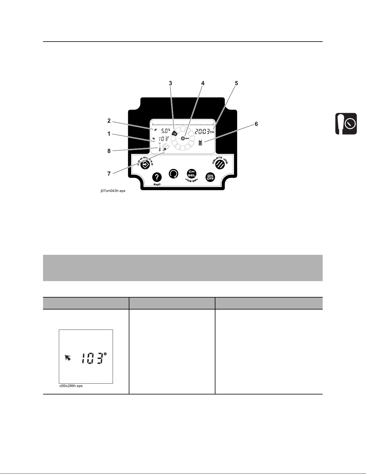
Ditch Witch Electronics 750/752 Display
Ditch Witch Electronics 750/752 Display
Indicators
1. Beacon temperature display
2. Pitch/slope indicator and percentage indicator
3. Roll indicator
4. Target indentifier indicator
IMPORTANT: Some items operate differently depending where data is being saved. Internal refers to
pipe data being saved to 750 Display memory. External refers to pipe data being sent to a properly
connected laptop computer running a version of Trac Management System software.
Item Description Notes
1. Beacon temperature
display
Indicates beacon temperature
in degrees Centigrade and
degrees Fahrenheit.
5. Depth estimate
6. Display battery status indicator
7. Beacon battery status indicator
8. Beacon temperature indicator
CMW

Controls - 54 JT2020 Mach 1 Operator’s Manual
Ditch Witch Electronics 750/752 Display
Item Description Notes
2. Pitch/slope indicator
and percentage
indicator
3. Roll indicator Indicates beacon roll angle.
4. Target identifier
indicator
Indicates pitch beacon
percent of grade.
Indicates approximate
beacon location.
Internal: shows pipe label and stored
pitch.
External: shows desired pitch.
Only one set of arrows is active at a
time.
5. Depth estimate Indicates beacon depth
estimate.
CMW
Internal: shows job number and
stored depth.
External: shows desired depth.

JT2020 Mach 1 Operator’s Manual Controls - 55
Ditch Witch Electronics 750/752 Display
Item Description Notes
6. Display battery status
indicator
7. Beacon battery status
indicator
8. Beacon temperature
indicator
Indicates display power from
drilling unit.
Indicates beacon battery
status.
Indicates beacon
temperature.
If all five bars are not showing, check
display power connections.
See beacon instruction sheet.
See beacon instruction sheet.
CMW

Controls - 56 JT2020 Mach 1 Operator’s Manual
Ditch Witch Electronics 750/752 Display
Controls
1. Delete button
2. On/Off button
3. Channel select button
IMPORTANT: Some items operate differently depending where data is being saved. Internal refers to
pipe data being saved to 750 Display memory. External refers to pipe data being sent to a properly
connected laptop computer running a version of Trac Management System software.
Item Description Notes
1. Delete button To delete current pipe, press.
Second function:
To delete all jobs in internal
logging memory, press with
Recall button.
4. Roll stop button
5. Recall button
6. Store button
Previous pipe number will appear in
numeric display when data is deleted.
CMW

JT2020 Mach 1 Operator’s Manual Controls - 57
Ditch Witch Electronics 750/752 Display
Item Description Notes
2. On/Off button To turn on, press.
To turn off, press again.
3. Channel select button To display current channel,
press and release.
To switch channels, press
and hold.
Second function:
To start a new job, press with
Recall button.
“Init” and job number will be
displayed.
4. Roll stop button This feature is not yet
available.
Unit defaults to last channel used
each time unit is turned on.
IMPORTANT: Make sure display and
tracker are set to the same channel.
5. Recall button To see data about pipe, press
and release.
Second function:
To access second functions,
press with other buttons.
Internal: shows data about previous
pipe.
External: shows data about next pipe.
CMW

Controls - 58 JT2020 Mach 1 Operator’s Manual
Ditch Witch Electronics 750/752 Display
Item Description Notes
6. Store button To display serial number,
press and hold while pressing
on/off button.
To store current pipe data,
press.
Second function:
To download all jobs stored in
internal logging memory:
• Press with Recall button
• Connect display to PC
running Trac
Management System
software.
Pipe number will appear in numeric
display when data is stored.
IMPORTANT: Pipe data cannot be
stored without a valid depth estimate.
CMW

JT2020 Mach 1 Operator’s Manual Operation Overview - 59
Operation Overview
Chapter Contents
Planning. . . . . . . . . . . . . . . . . . . . . . . . . . . . . . . . . . 60
Setting Up at Jobsite . . . . . . . . . . . . . . . . . . . . . . . 60
Drilling . . . . . . . . . . . . . . . . . . . . . . . . . . . . . . . . . . . 61
Backreaming . . . . . . . . . . . . . . . . . . . . . . . . . . . . . . 62
Leaving Jobsite. . . . . . . . . . . . . . . . . . . . . . . . . . . . 62
Storing Equipment . . . . . . . . . . . . . . . . . . . . . . . . . 62
CMW

Operation Overview - 60 JT2020 Mach 1 Operator’s Manual
Planning
Planning
1. Gather information about jobsite. See page 65.
2. Inspect jobsite. See page 66.
3. Classify jobsite. See page 68.
4. Plan bore path. See page 71.
5. Check supplies and prepare equipment. See page 76.
6. Load equipment. See page 85.
Setting Up at Jobsite
1. Prepare jobsite. See page 76.
2. Unload drilling unit from trailer. See page 88.
3. Assemble drill string. See page 97.
4. Position drilling unit and drill frame. See page 93.
5. Assemble strike system. See page 116.
6. Anchor drilling unit. See page 115.
7. Connect fluid system. See page 93.
8. Calibrate tracker with beacon that will be installed in beacon housing. See tracker operator’s manual.
CMW

JT2020 Mach 1 Operator’s Manual Operation Overview - 61
Drilling
Drilling
1. Start system. See page 93.
2. Engage tracker control if desired. See page 127.
3. Drill first pipe. See page 100.
4. Record bore path. See page 105.
5. Enable automated pipeloader system. See page 105.
6. Add pipe. See page 102.
7. Drill remaining pipes in pipe box.
• Correct direction. See page 104.
• Engage cruise control. See page 146.
• Shift pipe box. See page 141.
8. Add up to a single column of drill pipe to empty box (see page 141) to complete bore.
9. Surface drill head. See page 106.
CMW

Operation Overview - 62 JT2020 Mach 1 Operator’s Manual
Backreaming
Backreaming
1. Assemble backream string. See page 107.
2. Start drilling unit and adjust throttle.
3. Set drilling fluid flow. Check that fluid flows through all nozzles. See page 122.
4. Remove pipe from bore. See page 109.
5. Remove up to a single column of drill pipe from full box (see page 137) to complete backream.
6. Remove pullback device. See page 111.
Backreaming Tips
• Plan backreaming job before drilling. Plan bore path as straight as possible. Check bend limits of
pullback material. Check that appropriate pullback devices are on hand.
• Keep all bends as gradual as possible.
• Drilling fluid quality is a key factor in backreaming success. Contact your Ditch Witch dealer for
information on testing water, selecting additives, and mixing drilling fluid.
• Backreaming requires more fluid than drilling. Make sure enough fluid is used.
Leaving Jobsite
1. Remove downhole tools. See page 111.
2. Remove anchors. See page 115.
3. Rinse unit and downhole tools. See page 156.
4. Disassemble strike system and disconnect from fluid system. See page 157.
5. Stow tools. See page 157.
6. Load unit onto trailer. See page 85.
Storing Equipment
1. For cold weather storage, antifreeze drilling unit. See page 154.
2. For long-term storage, disconnect battery disconnect switch.
CMW

JT2020 Mach 1 Operator’s Manual Prepare - 63
Prepare
Chapter Contents
Gather Information . . . . . . . . . . . . . . . . . . . . . . . . . 65
• Review Job Plan . . . . . . . . . . . . . . . . . . . . . . . . . . . . . . . . . . . . . . . . . . 65
• Notify One-Call Services. . . . . . . . . . . . . . . . . . . . . . . . . . . . . . . . . . . . 65
• Examine Pullback Material . . . . . . . . . . . . . . . . . . . . . . . . . . . . . . . . . . 65
• Arrange for Traffic Control. . . . . . . . . . . . . . . . . . . . . . . . . . . . . . . . . . . 65
• Plan for Emergency Services . . . . . . . . . . . . . . . . . . . . . . . . . . . . . . . . 65
Inspect Site . . . . . . . . . . . . . . . . . . . . . . . . . . . . . . . 66
• Identify Hazards . . . . . . . . . . . . . . . . . . . . . . . . . . . . . . . . . . . . . . . . . . 66
• Select Start and End Points . . . . . . . . . . . . . . . . . . . . . . . . . . . . . . . . . 67
Classify Jobsite. . . . . . . . . . . . . . . . . . . . . . . . . . . . 68
• Inspect Jobsite . . . . . . . . . . . . . . . . . . . . . . . . . . . . . . . . . . . . . . . . . . . 68
• Select a Classification. . . . . . . . . . . . . . . . . . . . . . . . . . . . . . . . . . . . . . 68
• Apply Precautions. . . . . . . . . . . . . . . . . . . . . . . . . . . . . . . . . . . . . . . . . 69
Plan Bore Path . . . . . . . . . . . . . . . . . . . . . . . . . . . . 71
• Recommended Bend Limits . . . . . . . . . . . . . . . . . . . . . . . . . . . . . . . . . 72
• Entry Pitch. . . . . . . . . . . . . . . . . . . . . . . . . . . . . . . . . . . . . . . . . . . . . . . 74
• Minimum Setback . . . . . . . . . . . . . . . . . . . . . . . . . . . . . . . . . . . . . . . . . 74
• Minimum Depth. . . . . . . . . . . . . . . . . . . . . . . . . . . . . . . . . . . . . . . . . . . 75
• Bore Path Calculator. . . . . . . . . . . . . . . . . . . . . . . . . . . . . . . . . . . . . . . 75
CMW

Prepare - 64 JT2020 Mach 1 Operator’s Manual
Prepare Jobsite . . . . . . . . . . . . . . . . . . . . . . . . . . . . 76
• Mark Bore Path. . . . . . . . . . . . . . . . . . . . . . . . . . . . . . . . . . . . . . . . . . . 76
• Prepare Entry Point. . . . . . . . . . . . . . . . . . . . . . . . . . . . . . . . . . . . . . . . 76
Check Supplies and Prepare Equipment . . . . . . . 77
• Check Supplies. . . . . . . . . . . . . . . . . . . . . . . . . . . . . . . . . . . . . . . . . . . 77
• Prepare Equipment. . . . . . . . . . . . . . . . . . . . . . . . . . . . . . . . . . . . . . . . 78
• Assemble Accessories . . . . . . . . . . . . . . . . . . . . . . . . . . . . . . . . . . . . . 78
CMW

JT2020 Mach 1 Operator’s Manual Prepare - 65
Gather Information
Gather Information
A successful job begins before the bore. The first step in planning is reviewing information already
available about the job and jobsite.
Review Job Plan
Review blueprints or other plans and make sure you have taken bore enlargement during backreaming
and pullback into account. Check for information about existing or planned structures, elevations, or
proposed work that may be taking place at the same time.
Notify One-Call Services
Contact your local One-Call (811 in USA) or the One-Call referral number (888-258-0808 in USA and
Canada) to have underground utilities located before digging. Also contact any utilities that do not
participate in the One-Call service.
Examine Pullback Material
Ask for a sample of the material you will be pulling back. Check its weight and stiffness. Contact the
manufacturer for bend radius information. Check that you have appropriate pullback devices.
Arrange for Traffic Control
If working near a road or other traffic area, contact local authorities about safety procedures and
regulations.
Plan for Emergency Services
Have the telephone numbers for local emergency and medical facilities on hand. Check that you will have
access to a telephone.
CMW

Prepare - 66 JT2020 Mach 1 Operator’s Manual
Inspect Site
Inspect Site
Inspect jobsite before transporting equipment. Check for the following:
• overall grade or slope
• changes in elevation such as hills or open trenches
• obstacles such as buildings, railroad crossings, or streams
• signs of utilities (See “Inspect Jobsite” on page 68.)
• traffic
• access
• soil type and condition
• water supply
• sources of locator interference (rebar, railroad tracks, etc.)
Take soil samples from several locations along bore path to determine best bit and backreamer
combinations.
Identify Hazards
Identify safety hazards and classify jobsite. See “Classify Jobsite” on page 68.
Jobsite hazards could cause death or serious injury. Use
correct equipment and work methods. Use and maintain proper safety
equipment.
NOTICE:
• Wear personal protective equipment including hard hat, safety eye wear, and hearing protection.
• Do not wear jewelry or loose clothing.
• Notify One-Call and companies which do not subscribe to One-Call.
• Comply with all utility notification regulations before digging or drilling.
• Verify location of previously marked underground hazards.
• Mark jobsite clearly and keep spectators away.
Remember, jobsite is classified by hazards in place -- not by line being installed.
CMW

JT2020 Mach 1 Operator’s Manual Prepare - 67
Inspect Site
Select Start and End Points
Select one end to use as a starting point. Consider the following when selecting a starting point:
Slope
Fluid system should be parked on a level site. Consider how slope will affect drilling unit setup, bending
pipe, and fluid flow out of hole.
Traffic
Vehicle and pedestrian traffic must be a safe distance from drilling equipment. Allow at least 10’ (3 m)
buffer zone around equipment.
Space
Check that starting and ending points allow enough space for gradual pipe bending. See “Minimum
Setback” on page 74.
Check that there is enough space to work and to set up electric strike system.
Comfort
Consider shade, wind, fumes, and other site features.
Drill downhill when possible so fluid will flow away from drilling unit.
CMW

Prepare - 68 JT2020 Mach 1 Operator’s Manual
Classify Jobsite
Classify Jobsite
Inspect Jobsite
• Follow U.S. Department of Labor regulations on excavating and trenching (Part 1926, Subpart P) and
other similar regulations.
• Contact your local One-Call (811 in USA) or the One-Call referral number (888-258-0808 in USA and
Canada) to have underground utilities located before digging. Also contact any utilities that do not
participate in the One-Call service.
• Inspect jobsite and perimeter for evidence of underground hazards, such as:
– “buried utility” notices
– utility facilities without overhead lines
– gas or water meters
– junction boxes
– drop boxes
– light poles
– manhole covers
– sunken ground
• Have an experienced locating equipment operator sweep area within 20’ (6 m) to each side of bore
path. Verify previously marked line and cable locations.
• Mark location of all buried utilities and obstructions.
• Classify jobsite.
Select a Classification
Jobsites are classified according to underground hazards present.
If working... then classify jobsite as...
within 10’ (3 m) of a buried electric line electric
within 10’ (3 m) of a natural gas line natural gas
in concrete, sand, or granite which is capable of producing
crystalline silica (quartz) dust
within 10’ (3 m) of any other hazard other
NOTICE: If you have any doubt about jobsite classification, or if jobsite might contain unmarked
hazards, take steps outlined previously to identify hazards and classify jobsite before working.
crystalline silica (quartz) dust
CMW

JT2020 Mach 1 Operator’s Manual Prepare - 69
Classify Jobsite
Apply Precautions
Once classified, precautions appropriate for jobsite must be taken.
Electric Jobsite Precautions
Electric shock. Contacting electric lines will cause death or serious injury.
Know location of lines and stay away.
In addition to using a directional drilling system with an electric strike system, use one or both of these
methods.
• Expose line by careful hand digging or soft excavation. Use beacon to track bore path. Have someone
observe clearance between drill head and backreamer when crossing a line.
• Have service shut down while work is in progress. Have electric company test lines before returning
them to service.
Natural Gas Jobsite Precautions
Fire or explosion possible. Fumes could ignite and cause burns. No
smoking, no flame, no spark.
Explosion possible. Serious injury or equipment damage could occur.
Follow directions carefully.
In addition to using a directional drilling system and positioning equipment upwind from gas lines, use one
or both of these methods.
• Expose lines by careful hand digging or soft excavation. Use beacon to track bore path. Have
someone observe clearance between drill head and backreamer when crossing a line.
• Have gas shut off while work is in progress. Have gas company test lines before returning them to
service.
CMW

Prepare - 70 JT2020 Mach 1 Operator’s Manual
Classify Jobsite
Crystalline Silica (Quartz) Dust Precautions
Jobsite hazards could cause death or serious injury. Use correct
equipment and work methods. Use and maintain proper safety equipment.
NOTICE: Cutting, drilling or working materials such as, concrete, sand or rock containing quartz may
result in exposure to silica dust. Use water spray or other means to control dust. If workers are exposed
to dust they must wear appropriate breathing protection. Silica dust may cause lung disease and is
known to the State of California to cause cancer.
Follow OSHA or other guidelines for exposure to crystalline silica when trenching, sawing or drilling
through material that might produce dust containing crystalline silica (quartz).
Other Jobsite Precautions
You may need to use different methods to safely avoid other underground hazards. Talk with those
knowledgeable about hazards present at each site to determine which precautions should be taken or if
job should be attempted.
CMW

JT2020 Mach 1 Operator’s Manual Prepare - 71
Plan Bore Path
Plan Bore Path
Plan the bore path, from entry to end, before drilling begins. The Ditch Witch Trac Management System
Plus is available for planning your bore path. This special software can be run in the field using a laptop
computer equipped with Windows
If not using Trac Management System Plus, mark the bore path on the ground with spray paint or flags, or
record it on paper for operator reference.
For complicated bores, consult an engineer. Have the jobsite surveyed and bore path calculated. Be sure
the engineer knows minimum entry pitch, bend limits of drill pipe, bend and tension limits of pullback
material, pipe lengths, and location of all underground utilities.
For less complicated bores, plan the bore based on four measurements:
• recommended bend limit
• entry pitch
• minimum setback
• minimum depth
®
95 or higher operating system. See your Ditch Witch dealer for details.
IMPORTANT: See the following pages for more information about these measurements. If not using
Trac Management System Plus, see “Bore Path Calculator” on page 75 and use these measurements to
help plan your bore.
CMW

Prepare - 72 JT2020 Mach 1 Operator’s Manual
Plan Bore Path
Recommended Bend Limits
Ditch Witch drill pipes are designed to bend slightly during operation. Slight bending allows for steering and
correcting direction. Bending beyond recommended limits will cause damage that might not be visible. This
damage adds up and will later lead to sudden drill pipe failure.
IMPORTANT: Consider recommended bend limits during any bend, not just during bore entry.
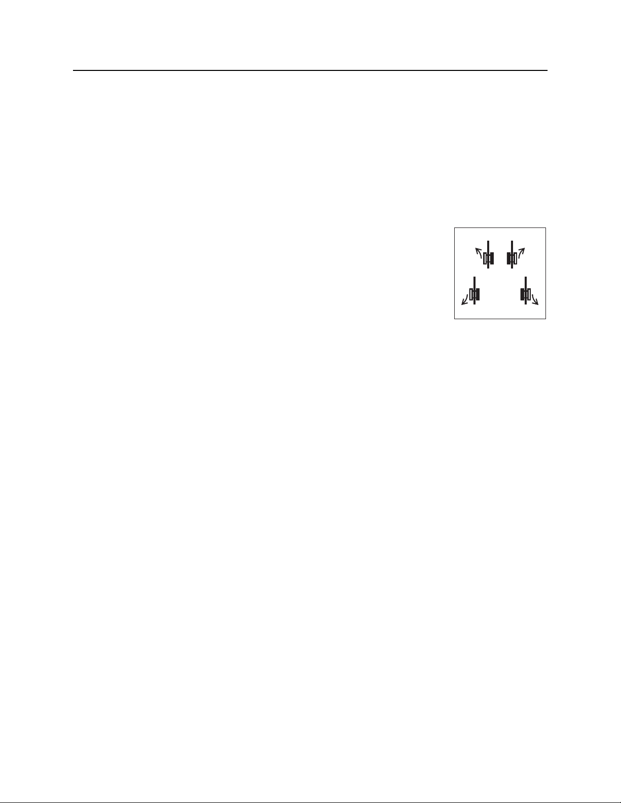
Pipe Pitch
Ditch Witch drill pipe is tested to bend at a maximum
percent pitch. For JT2020 Mach 1 drill pipe, make sure
pitch (A) changes no more than 7% over the full length
of each pipe.
NOTICE: Bending drill pipe more sharply than
recommended will damage pipe and cause failure
over time. Changes in pitch must be equally
distributed over the length of a pipe. Maximum
changes in pitch within 1-2’ (300-600 mm) of pipe
create sharp bends that will damage pipe.
Monitor the pitch of each pipe with the 750 Display on
the operator’s console. See page 53.
Bend Radius
JT2020 Mach 1 drill pipes have a tested minimum
bend radius of 130’ (40 m). This means that a 90degree bend in the bore path:
• has a radius (A) of 130’ (40 m)
• requires approximately 204’ (62 m) of drill pipe
(B).
NOTICE: Bending drill pipe more sharply than
recommended will damage the pipe and cause
failure over time.
• If bend radius is reduced, drill pipe life is
reduced.
• If bend radius is increased, drill pipe life is
increased.
IMPORTANT: Use the charts on the next page to keep bends within safe limits.
CMW

JT2020 Mach 1 Operator’s Manual Prepare - 73
Plan Bore Path
Pipe-By-Pipe Bend Limits
Pipe
(C)
1 10 ft 0 in (3.0 m) 0 ft 5 in (0.1 m) 12 103 ft 8 in (31.6 m) 51 ft 7 in (15.7 m)
2 19 ft 11 in (6.1 m) 1 ft 6 in (0.5 m) 13 109 ft 5 in (33.3 m) 59 ft 9 in (18.2 m)
3 29 ft 9 in (9.1 m) 3 ft 5 in (1.1 m) 14 1114 ft 6 in (34.9 m) 68 ft 5 in (20.8 m)
4 39 ft 4 in (12.0 m) 6 ft 1 in (1.9 m) 15 118 ft 10 in (36.2 m) 77 ft 4 in (23.6 m)
5 48 ft 9 in (14.9 m) 9 ft 6 in (2.9 m) 16 122 ft 7 in (37.4 m) 86 ft 8 in (26.4 m)
6 57 ft 11 in (17.6 m) 13 ft 7 in (4.1 m) 17 125 ft 6 in (38.3 m) 96 ft 2 in (29.3 m)
7 66 ft 8 in (20.3 m) 18 ft 5 in (5.6 m) 18 127 ft 9 in (38.9 m) 105 ft 11 in (32.3 m)
8 75 ft 1 in (22.9 m) 23 ft 10 in (7.3 m) 19 129 ft 3 in (39.4 m) 115 ft 10 in (35.3 m)
9 83 ft 0 in (25.3 m) 29 ft 11 in (9.1 m) 20 129 ft 11 in (39.6 m) 125 ft 10 in (38.3 m)
10 90 ft 5 in (27.6 m) 36 ft 7 in (11.2 m) 20.4 130 ft 0 in (39.6 m) 130 ft 0 in (39.6 m)
11 97 ft 4 in (29.7 m) 43 ft 10 in (13.4 m)
Forward (B) Deflection (A) Pipe
(C)
Forward (B) Deflection (A)
Pipe 10 is illustrated.
CMW

Prepare - 74 JT2020 Mach 1 Operator’s Manual
Plan Bore Path
Entry Pitch
Entry pitch is the slope of the drill frame compared with the slope of the ground. Determine entry pitch one
of two ways:
1. With Pitch Beacon
• Lay pitch beacon on the ground and read
pitch.
• Lay pitch beacon on drill frame and read pitch.
• Subtract ground pitch from drilling unit pitch.
2. With Measurements
• Measure from the ground to front end of drill
frame (H1).
• Measure from the ground to back end of frame
(H2).
• Subtract (H1) from (H2). Record this number.
• Measure the distance between front and back
points (C).
• Divide (H2-H1) by (C), then multiply by 100.
This is your pitch.
IMPORTANT: A shallow entry pitch (A1) allows you
to reach horizontal sooner and with less bending.
Increasing entry pitch (A2) makes bore path longer
and deeper.
Minimum Setback
Setback is the distance from the entry point to where
pipe becomes horizontal (B1).
NOTICE: If setback is too small (B2), you will
exceed bend limits and damage the pipe.
CMW

JT2020 Mach 1 Operator’s Manual Prepare - 75
Plan Bore Path
Minimum Depth
Because you must bend pipe gradually, entry pitch and
bend limits determine how deep the pipe will be when
it becomes horizontal. This is called the minimum
depth.
• To reduce minimum depth (D1), reduce entry
pitch. This also decreases setback.
• To increase minimum depth (D2), increase
entry pitch. This also increases setback.
Bore Path Calculator
Entry pitch, setback, and minimum depth work together with bend limits to determine the bore path. To find
the setback (B) and entry pitch (A) that will take you to the desired minimum depth (D), use the chart
below.
Minimum depth (D) Entry pitch (A) Setback (B) Depth to begin steering (S)
3 ft 7 in (1.1 m) -18% 31 ft 7 in (9.6 m) 1 ft 6 in (0.46 m)
4 ft 3 in (1.3 m) -20% 34 ft 0 in (10.4 m) 1 ft 8 in (0.51 m)
4 ft 11 in (1.5 m) -22% 36 ft 5 in (11.1 m) 1 ft 10 in (0.56 m)
5 ft 7 in (1.7 m) -24% 38 ft 9 in (11.8 m) 2 ft 0 in (0.61 m)
6 ft 4 in (1.9 m) -26% 41 ft 1 in (12.5 m) 2 ft 2 in (0.66 m)
IMPORTANT: Numbers in table based on 130’ (40 m) minimum bend radius, beacon housing, EZ-
Connect, connector, transition sub, and 1/3 of first drill pipe (L, totalling 8’ 8” [2.6 m]) in the ground
before steering.
CMW

Prepare - 76 JT2020 Mach 1 Operator’s Manual
Prepare Jobsite
Prepare Jobsite
Jobsite hazards could cause death or serious injury. Use
correct equipment and work methods. Use and maintain proper safety
equipment.
NOTICE:
• If jobsite classification is in question or if the possibility of unmarked electric utilities exists, classify
jobsite as electric.
• Cutting high voltage cable can cause electrocution. Expose lines by hand before digging.
• All vegetation near operator’s station must be removed. Contact with trees, shrubs, or weeds during
electrical strike could result in electrocution.
Mark Bore Path
Mark your planned bore path and all located utility lines with flags or paint.
Prepare Entry Point
For bore to be successful, first pipe must be straight as
it enters the ground.
To help ensure that the first pipe does not bend, dig a
small starting hole so that the first pipe is drilled into a
vertical surface.
To prevent bending or straining pipe, position drilling
unit for straight entry.
CMW

JT2020 Mach 1 Operator’s Manual Prepare - 77
Check Supplies and Prepare Equipment
Check Supplies and Prepare Equipment
Check Supplies
• receiver/transmitter or tracker with spare batteries
• beacons with new and spare batteries
• two-way radios with new and spare batteries
• quick wrench (see page 135)
• transition sub
• anchoring equipment and accessories
• bits, screens, nozzles (see page 130)
• adapters, pipe, beacon housings
• marking flags or paint
• water and additional hoses
• fuel
• drilling fluid additives (see page 130)
• spare fuses
• keys
• backreamers, swivels, pulling devices (see page 130)
• wash down hose and spray gun
• duct tape
• spray lubricant
• tool joint compound (see page 163)
• electrically insulating boots and gloves
• personal protective equipment, such as hard hat and safety glasses
• notepad and pencil
CMW

Prepare - 78 JT2020 Mach 1 Operator’s Manual
Prepare Equipment
Fluid Levels
• fuel
• hydraulic fluid
• engine coolant
• battery charge
• engine oil
Condition and Function
• filters (air, oil, hydraulic)
• fluid pump
• couplers
• tires and tracks
• pumps and motors
• drilling fluid mixer
• hoses and valves
• water tanks
Assemble Accessories
Fire Extinguisher
If required, mount a fire extinguisher near the power unit but away from possible points of ignition. The fire
extinguisher should always be classified for both oil and electric fires. It should meet legal and regulatory
requirements.
CMW

JT2020 Mach 1 Operator’s Manual Drive - 79
Drive
Chapter Contents
Start Unit . . . . . . . . . . . . . . . . . . . . . . . . . . . . . . . . . 80
Steer Unit . . . . . . . . . . . . . . . . . . . . . . . . . . . . . . . . 80
Shut Down Unit . . . . . . . . . . . . . . . . . . . . . . . . . . . 81
CMW
Drive - 80 JT2020 Mach 1 Operator’s Manual
Start Unit
Start Unit
1. Insert key.
2. Turn key clockwise. See page 23 for more information.
3. Run engine at low throttle for 5 minutes.
Steer Unit
To steer drilling unit while using tethered ground drive controller, follow instructions
for type of steering desired.
To steer while moving forward, push forward and then move to left or right.
Drilling unit will gradually turn to left or right.
To steer while moving backward, pull back and then move to left or right. Drilling
unit will gradually turn to left or right.
c00ic145h.eps
For tight steering in low speed, move control to center position and then to a corner. Tracks will counterrotate and turn drilling unit in a tight circle.
Tips to Reduce Track Wear
Rubber tracks are best suited at soil-based job sites with minimal rock and debris. Sharp objects such as
gravel, steel shards, and broken concrete will damage rubber tracks and undercarriage components.
Excessive operation on concrete or asphalt will shorten track life. When storing your machine, keep tracks
away from rain and direct sunlight.
Wash tracks daily to remove foreign objects and abrasive soil from sprockets and idler rollers. Drive slowly
and make wide turns when possible. Regularly check undercarriage components (sprocket, rollers, idler)
for wear and damage. Maintain proper track tension. (See “Check Track Tension and Condition” on
page 189.)
To prevent premature wear, avoid the following:
• Spinning tracks under heavy load.
• Turning on sharp objects such as stones, stumps and debris.
• Quick turns or “spin” turns on asphalt or concrete.
• Driving over curbs, ledges, and sharp objects.
• Driving with sidewall edges pressed against hard walls, curbs or other objects.
• Driving on slopes.
• Operating on corrosive materials such as salt or fertilizer. Wash immediately.
CMW

JT2020 Mach 1 Operator’s Manual Drive - 81
Shut Down Unit
Shut Down Unit
1. Stop track movement.
2. Lower drill frame and stabilizers to the ground.
IMPORTANT: If frame and stabilizers cannot be lowered, use cylinder locks or other suitable
material to block the tracks and frame. Remove cylinder locks or chocks before driving unit.
3. Run engine at low throttle for 3 minutes to cool.
4. Turn key to the stop position.
5. Remove key.
CMW

Drive - 82 JT2020 Mach 1 Operator’s Manual
Shut Down Unit
CMW

JT2020 Mach 1 Operator’s Manual Transport - 83
Transport
Chapter Contents
Lift . . . . . . . . . . . . . . . . . . . . . . . . . . . . . . . . . . . . . . 84
Haul . . . . . . . . . . . . . . . . . . . . . . . . . . . . . . . . . . . . . 85
• Load . . . . . . . . . . . . . . . . . . . . . . . . . . . . . . . . . . . . . . . . . . . . . . . . . . . 85
• Tie Down . . . . . . . . . . . . . . . . . . . . . . . . . . . . . . . . . . . . . . . . . . . . . . . 86
• Unload . . . . . . . . . . . . . . . . . . . . . . . . . . . . . . . . . . . . . . . . . . . . . . . . . 88
Tow . . . . . . . . . . . . . . . . . . . . . . . . . . . . . . . . . . . . . 89
CMW

Transport - 84 JT2020 Mach 1 Operator’s Manual
Lift
Lift
This machine is not configured for lifting. If the machine must be lifted, load machine into a container or
onto a platform appropriate for lifting. See “Specifications” for weight of machine.
CMW

JT2020 Mach 1 Operator’s Manual Transport - 85
Haul
Haul
Load
Crushing weight. If load falls or moves it could kill or crush you. Use
proper procedures and equipment or stay away.
NOTICE:
• Load and unload trailer on level ground.
• Verify that trailer wheels are blocked.
• Incorrect loading can cause trailer swaying.
• Attach trailer to vehicle before loading or unloading.
• Ten to fifteen percent of total vehicle weight (equipment plus trailer) must be on tongue to help
prevent trailer sway.
With Tiedown Kit
1. Start drilling unit engine.
2. Using tethered ground drive controller, pull power mode switch into low position. See page 26.
3. Move drilling unit to rear of trailer and align with ramps.
4. Slowly drive unit onto trailer until track reaches chock.
5. Lower drill frame to drill frame rest.
6. Back unit until front of drill frame is seated in rest.
7. Lower stabilizers to trailer floor.
8. Stop engine.
9. Attach tiedowns at rear of unit where indicated on page 86.
Without Tiedown Kit
1. Start drilling unit engine.
2. Using tethered ground drive controller, pull power mode switch into low position. See page 26.
3. Move drilling unit to rear of trailer and align with ramps.
4. Slowly drive unit onto trailer until track reaches chock.
5. Lower stabilizers to trailer floor.
6. Lower drill frame to trailer floor.
7. Stop engine when unit is safely positioned on trailer bed for proper tongue weight.
8. Attach tiedowns to drilling unit where indicated on page 86.
CMW

Transport - 86 JT2020 Mach 1 Operator’s Manual
Haul
Tie Down
Points
Tiedown points are identified by tiedown decals. Securing to trailer at other
points is unsafe and can damage machinery.
Procedure
Incorrect procedures could result in death, injury, or property damage.
Learn to use equipment correctly.
NOTICE: Wrenches can open after engine shutdown. Ensure that any downhole tool or pipe in tool joint
vises is attached to spindle or removed before transport.
With Tiedown Kit
Loop tiedowns around rear tiedown points. Make sure tiedowns are tight before transporting.
CMW

JT2020 Mach 1 Operator’s Manual Transport - 87
Haul
Without Tiedown Kit
Loop tiedowns around unit at tiedown points. Make sure tiedowns are tight before transporting.
CMW

Transport - 88 JT2020 Mach 1 Operator’s Manual
Haul
Unload
Crushing weight. If load falls or moves it could kill or crush you. Use
proper procedures and equipment or stay away.
NOTICE:
• Load and unload trailer on level ground.
• Ensure trailer wheels are blocked.
• Attach trailer to vehicle before loading or unloading.
With Tiedown Kit
1. Lower ramps.
2. Remove tiedowns.
3. Start drilling unit engine.
4. Using tethered ground drive controller, pull power mode switch into low position. See page 26.
5. Raise stabilizers.
6. Move drilling unit forward until track meets chock.
7. Raise drill frame.
8. Slowly back unit down trailer or ramps.
Without Tiedown Kit
1. Lower ramps.
2. Remove tiedowns.
3. Start drilling unit engine.
4. Using tethered ground drive controller, pull power mode switch into low position. See page 26.
5. Raise stabilizers.
6. Raise drill frame.
7. Slowly back unit down trailer or ramps.
CMW

JT2020 Mach 1 Operator’s Manual Transport - 89
Tow
Tow
Under normal conditions, drilling unit should not be towed. If unit breaks down and towing is necessary:
• Attach chains to indicated tow points facing towing vehicle.
• Open bypass valves.
• Open selector valves.
• Tow for short distances at less than 1 mph (1.6 km/h).
• Use maximum towing force of 1.5 times unit weight.
To open bypass valves for towing, rotate valve stems (shown) two full revolutions.
NOTICE: Do not open valves more than two turns.
To close bypass valves and return to normal operation, torque valve stems (shown) to 7-10 ft•lb (9.5-14
N•m).
NOTICE: Do not over-tighten bypass valves.
CMW

Transport - 90 JT2020 Mach 1 Operator’s Manual
Tow
To open selector valves for towing, loosen jam nut and tighten valve screw (shown) until it is fully
threaded.
To close selector valves and return to normal operation, unthread valve screw and tighten jam nut. To
attach chains to tow points, determine which points are facing towing vehicle.
To attach chains to tow points, determine which points are facing towing vehicle.
If back tow points are facing towing vehicle, loop chains through each tow point and bring them together to
a central pull point.
If front tow points are facing towing vehicle, loop chain through tow point and pull straight forward.
CMW

JT2020 Mach 1 Operator’s Manual Conduct a Bore - 91
Conduct a Bore
Chapter Contents
Position Equipment . . . . . . . . . . . . . . . . . . . . . . . . 93
Connect Fluid System . . . . . . . . . . . . . . . . . . . . . . 93
Start System . . . . . . . . . . . . . . . . . . . . . . . . . . . . . . 93
Prime Drilling Fluid Pump . . . . . . . . . . . . . . . . . . . 94
Operate Carriage Control . . . . . . . . . . . . . . . . . . . 95
Clamp Pipe . . . . . . . . . . . . . . . . . . . . . . . . . . . . . . . 96
Assemble Drill String . . . . . . . . . . . . . . . . . . . . . . . 97
• Prepare Beacon Housing . . . . . . . . . . . . . . . . . . . . . . . . . . . . . . . . . . . 97
• Attach Transition Sub . . . . . . . . . . . . . . . . . . . . . . . . . . . . . . . . . . . . . . 98
• Connect Drill Pipe . . . . . . . . . . . . . . . . . . . . . . . . . . . . . . . . . . . . . . . . 99
Drill First Pipe . . . . . . . . . . . . . . . . . . . . . . . . . . . . 100
Enable Automated Pipeloader System . . . . . . . 101
Add Pipe . . . . . . . . . . . . . . . . . . . . . . . . . . . . . . . . 102
Correct Direction . . . . . . . . . . . . . . . . . . . . . . . . . 104
• Basic Rules . . . . . . . . . . . . . . . . . . . . . . . . . . . . . . . . . . . . . . . . . . . . 104
• Procedure . . . . . . . . . . . . . . . . . . . . . . . . . . . . . . . . . . . . . . . . . . . . . . 104
• Drill Head Position . . . . . . . . . . . . . . . . . . . . . . . . . . . . . . . . . . . . . . . 105
CMW

Conduct a Bore - 92 JT2020 Mach 1 Operator’s Manual
Record Bore Path . . . . . . . . . . . . . . . . . . . . . . . . . 105
Surface Drill Head . . . . . . . . . . . . . . . . . . . . . . . . 106
Assemble Backream String . . . . . . . . . . . . . . . . 107
Remove Pipe . . . . . . . . . . . . . . . . . . . . . . . . . . . . 109
Remove Pullback Device . . . . . . . . . . . . . . . . . . . 111
CMW

JT2020 Mach 1 Operator’s Manual Conduct a Bore - 93
Position Equipment
Position Equipment
1. Review bore plan and select drilling unit position and fluid unit position. See “Select Start and End
Points” on page 67.
2. Move equipment into selected positions.
Connect Fluid System
Electric shock. Contacting electric lines will cause death or serious injury.
Know location of lines and stay away.
NOTICE: If an electrical strike occurs while drilling unit is connected to a fluid system, the
fluid system will also become electrified. Do not connect drilling unit to a public or private
(business or home) water supply.
1. Connect fluid hose from mixing system to drilling
fluid pump. A 1.5” (38 mm) or larger, non-collapsible
hose is required.
2. Install y-strainer between mixing unit and drilling
fluid pump. Position strainer so that drilling fluid
flows in the direction of the arrow. In most cases,
positioning strainer at outlet of mixing unit gives
best results.
IMPORTANT:
• Clean y-strainer regularly. See page 172.
• Prime the remote drilling fluid pump after
switching to a new tank. See page 94.
Start System
1. Start drilling unit and remote fluid unit. Allow both engines to warm up.
IMPORTANT: Ensure that mixture of drilling fluid matches drilling conditions. See “Drilling Fluid”
on page 122.
2. Enable tracker control mode if desired. See “Tracker Control” on page 127.
3. Press top of drilling unit throttle switch until engine is at full throttle. If you do not want to use
autothrottle mode, return switch to center position.
CMW

Conduct a Bore - 94 JT2020 Mach 1 Operator’s Manual
Prime Drilling Fluid Pump
Prime Drilling Fluid Pump
Incorrect procedures could result in death, injury, or property damage.
Learn to use equipment correctly.
NOTICE: Failure to prime the drilling fluid pump will cause flow fluctuations, which will
make it difficult to control the washwand.
Pressurized fluid or air could pierce skin and cause injury
or death. Stay away.
Prime drilling fluid pump each time tank is changed. To prime the pump:
1. Fill drilling fluid hose and connect hose to unit.
2. Operate mixing/transfer pump at full speed for 1 - 3 minutes to discharge air from system.
3. Return mixing/transfer pump to normal operating speed and continue the bore.
4. If drilling fluid pressure surges are observed, repeat step 2.
CMW

JT2020 Mach 1 Operator’s Manual Conduct a Bore - 95
Operate Carriage Control
Operate Carriage Control
The thrust/rotation control has eight positions which allow the four basic
functions to be combined. The chart below summarizes functions that occur
when control is put at a combined position. Operator must be in seat for
control to function.
Carriage Movement Rotation Direction
forward clockwise (makeup)
reverse counterclockwise (breakout)
CMW

Conduct a Bore - 96 JT2020 Mach 1 Operator’s Manual
Clamp Pipe
Clamp Pipe
Turning shaft can kill you or crush arm or leg. Stay away.
NOTICE: Clamping anywhere else on the pipe will weaken the pipe. Pipe can later break,
even when operating under normal loads.
Incorrect procedures could result in death, injury, or property damage.
Learn to use equipment correctly.
NOTICE: Wrenches can open after engine shutdown. Ensure that any downhole tool or pipe in tool joint
vises is attached to spindle or removed before transport.
Clamp on pipe when joint is centered between
wrenches (1 and 2). Always clamp on the larger
diameter areas on either side of the tool joint face.
CMW

JT2020 Mach 1 Operator’s Manual Conduct a Bore - 97
Assemble Drill String
Assemble Drill String
Prepare Beacon Housing
1. Select nozzles and bit.
IMPORTANT: A variety of nozzles and bits
are available to suit your particular job
conditions. See “Downhole Tools” on
page 130 for more information, or contact
your Ditch Witch dealer.
2. Insert nozzle into beacon housing.
3. Attach bit (2) to beacon housing (1).
4. Install beacon, following beacon instructions for:
• battery replacement
• beacon positioning
5. Install beacon housing lid. See “Beacon Housings”
on page 131.
6. Follow beacon instructions to check beacon operation.
7. Follow tracker instructions to calibrate beacon.
CMW

Conduct a Bore - 98 JT2020 Mach 1 Operator’s Manual
Assemble Drill String
Attach Transition Sub
Moving tools will kill or injure. Shut off drill string power when anyone can
be struck by moving or thrown tools. Never use pipe wrenches on drill string.
Use either machine torque or quick wrench to attach transition sub (2) to beacon housing (1).
Machine Torque
1. Pull beacon housing into front wrench.
2. Close wrench.
3. Lube joints.
4. Slowly make up joint.
5. Use full machine torque to tighten joint fully.
Quick Wrench
1. Lube joints with TJC.
2. Attach quick wrench to the joint in the join position and tighten joint. See “Quick Wrench” on page 135.
CMW

JT2020 Mach 1 Operator’s Manual Conduct a Bore - 99
Assemble Drill String
Connect Drill Pipe
1. Start drilling unit engine.
2. Align drill pipe in front wrench.
3. Clamp tool joint in front wrench. See “Clamp Pipe” on page 96.
4. Load pipe:
• Make sure pipe box is positioned correctly.
• Lower pipe lifters.
• Close grippers.
• Lubricate pipe threads (pipe loader end).
• Lubricate pipe threads (front wrench end).
• Move pipe to spindle.
• Raise pipe lifters.
5. Connect pipe:
• Move carriage forward until pipe joints meet at front wrench.
• Rotate spindle clockwise. Carriage will move forward as pipe threads tighten.
• Rotate clockwise until spindle stops turning, and joint is fully tightened.
• Open grippers.
• Retract shuttles fully.
• Open front wrench.
CMW
 Loading...