


JT20
Operator’s
Manual
CMW
®
Issue 1.0
053-2633

JT20 Operator’s Manual Overview - 1
Overview
Chapter Contents
Serial Number Location . . . . . . . . . . . . . . . . . . . . . . 2
Intended Use . . . . . . . . . . . . . . . . . . . . . . . . . . . . . . . 3
Equipment Modification . . . . . . . . . . . . . . . . . . . . . . 3
Unit Components . . . . . . . . . . . . . . . . . . . . . . . . . . . 4
Operator Orientation. . . . . . . . . . . . . . . . . . . . . . . . . 5
About This Manual . . . . . . . . . . . . . . . . . . . . . . . . . . 5
• Bulleted Lists. . . . . . . . . . . . . . . . . . . . . . . . . . . . . . . . . . . . . . . . . . . . . . 5
• Numbered Lists. . . . . . . . . . . . . . . . . . . . . . . . . . . . . . . . . . . . . . . . . . . . 5
• “Continued” Indicators. . . . . . . . . . . . . . . . . . . . . . . . . . . . . . . . . . . . . . . 5
CMW
®
Overview - 2 JT20 Operator’s Manual
Serial Number Location
Serial Number Location
Record serial numbers and date of purchase in spaces provided. Drilling unit serial number is located as
shown.
Item
date of manufacture
date of purchase
drilling unit serial number
engine serial number
trailer serial number
CMW
®

JT20 Operator’s Manual Overview - 3
Intended Use
Intended Use
The JT20 is a self-contained horizontal directional drilling unit designed to install buried cable and pipe at
distances to 400’ (122 m) depending on soil conditions.
The unit is designed for operation in temperatures typically experienced in earth moving and construction
work environments. Provisions may be required to operate in extreme temperatures. Contact your Ditch
®
Witch
The JT20 can be used with Ditch Witch drilling fluid units and Ditch Witch locating equipment. It should be
operated, serviced, and repaired only by persons familiar with its particular characteristics and acquainted
with the relevant safety procedures.
dealer. Use in any other way is considered contrary to the intended use.
Equipment Modification
This equipment was designed and built in accordance with applicable standards and regulations.
Modification of equipment could mean that it will no longer meet regulations and may not function properly
or in accordance with the operating instructions. Modification of equipment should only be made by
competent personnel possessing knowledge of applicable standards, regulations, equipment design
functionality/requirements and any required specialized testing.
CMW
®
Overview - 4 JT20 Operator’s Manual
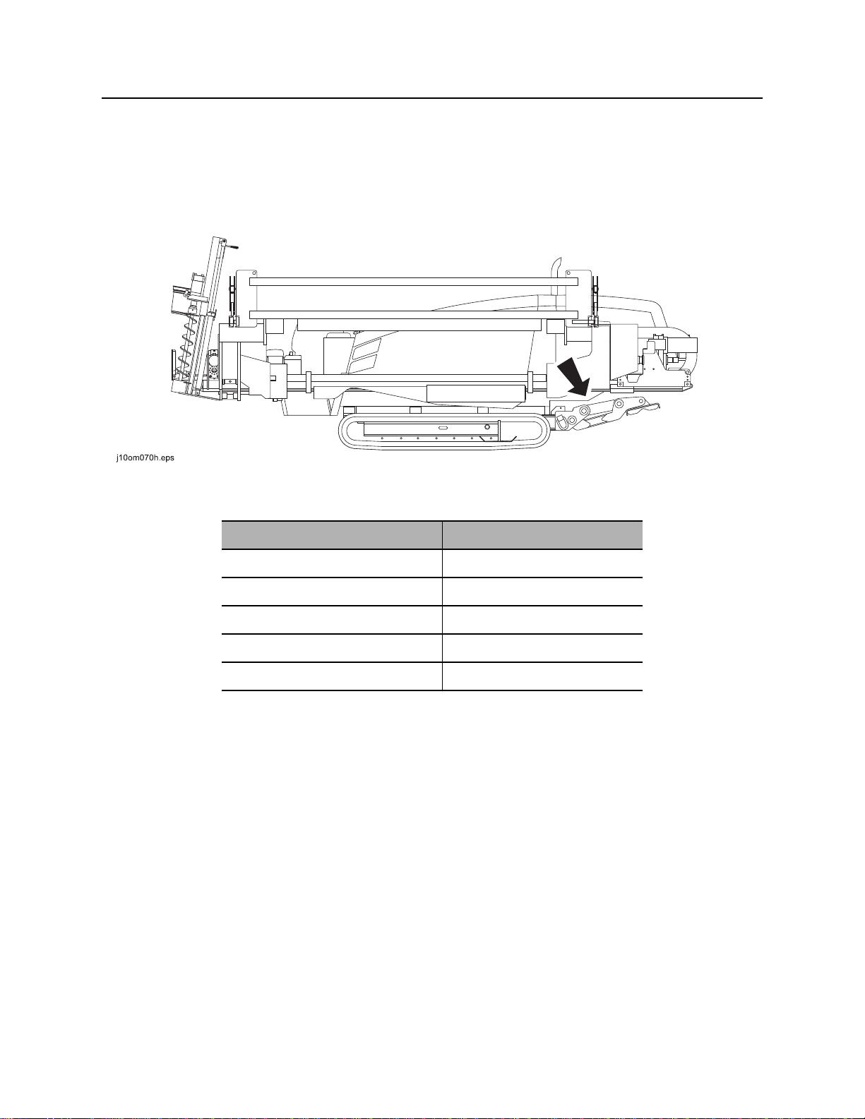
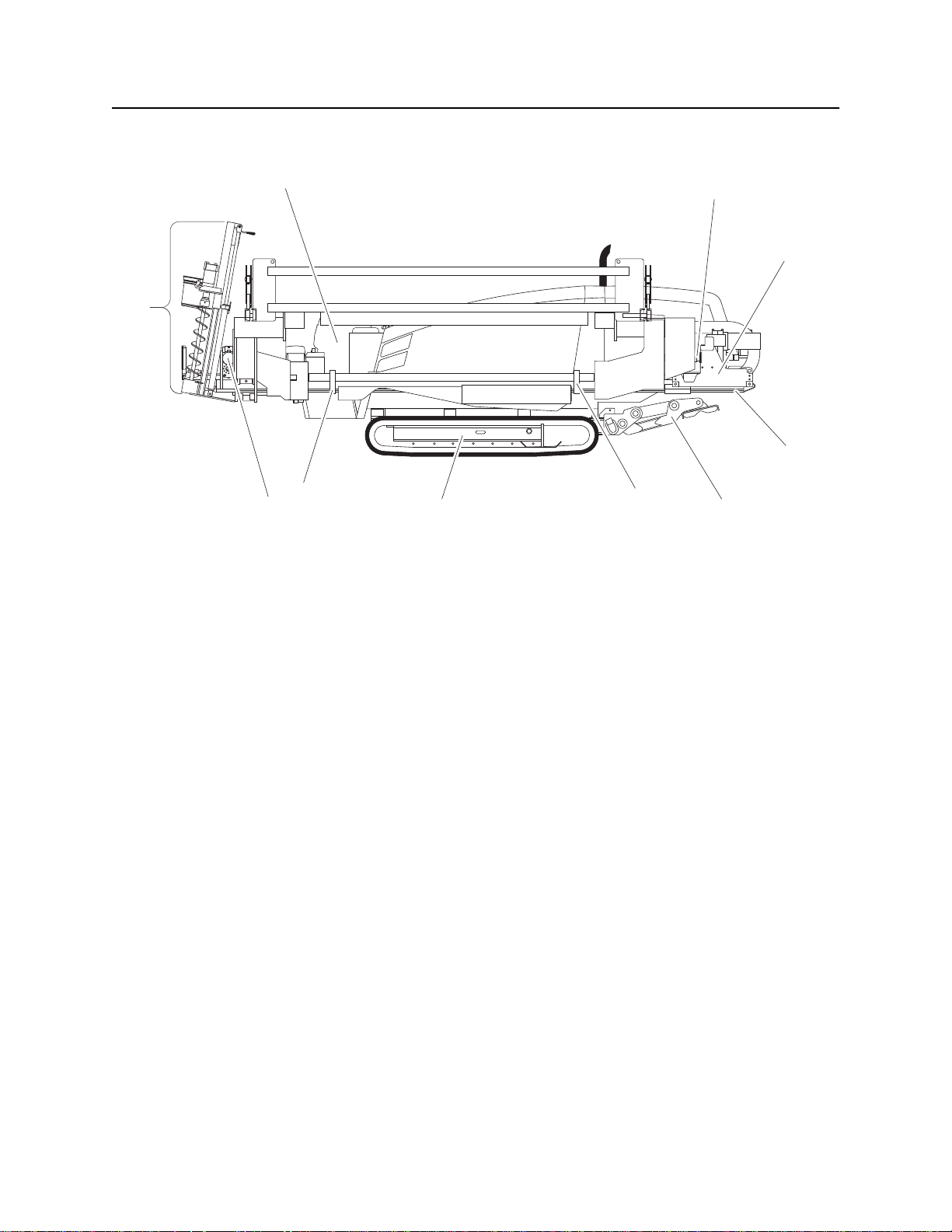
Unit Components
Unit Components
9
j10om001h.eps
1. Operator’s station
2. Spindle
1
2
3
4
6
78
6. Pipeloader
7. Tracks
6
5
3. Carriage
4. Drill frame
5. Stabilizer
8. Vise wrenches
9. Anchoring system
CMW
®
JT20 Operator’s Manual Overview - 5
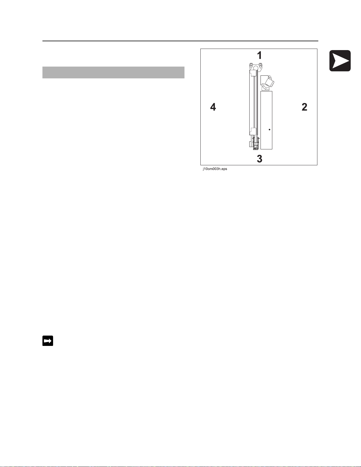
Operator Orientation
Operator Orientation
IMPORTANT: Top view of unit is shown.
1. Front of unit
2. Right side of unit
3. Rear of unit
4. Left side of unit
About This Manual
This manual contains information for the proper use of this machine. See the beige Operation Overview
pages for basic operating procedures. Cross references such as “See page 50” will direct you to detailed
procedures.
Bulleted Lists
Bulleted lists provide helpful or important information or contain procedures that do not have to be
performed in a specific order.
Numbered Lists
Numbered lists contain illustration callouts or list steps that must be performed in order.
“Continued” Indicators
indicates that a procedure is continued on the next page.
CMW
®

Overview - 6 JT20 Operator’s Manual
About This Manual
CMW
®

JT20 Operator’s Manual Foreword - 7
Foreword
This manual is an important part of your equipment. It provides safety information and operation
instructions to help you use and maintain your Ditch Witch
Read this manual before using your equipment. Keep it with the equipment at all times for future reference.
If you sell your equipment, be sure to give this manual to the new owner.
If you need a replacement copy, contact your Ditch Witch dealer. If you need assistance in locating a
dealer, visit our website at www.ditchwitch.com or write to the following address:
The Charles Machine Works, Inc.
Attn: Marketing Department
PO Box 66
Perry, OK 73077-0066
USA
The descriptions and specifications in this manual are subject to change without notice. The Charles
Machine Works, Inc. reserves the right to improve equipment. Some product improvements may have
taken place after this manual was published. For the latest information on Ditch Witch equipment, see your
Ditch Witch dealer.
®
equipment.
Thank you for buying and using Ditch Witch equipment.
CMW
®

Foreword - 8 JT20 Operator’s Manual
JT20
Operator’s Manual
Issue number 1.0/OM-5/13
Part number 053-2633
Copyright 2013
by The Charles Machine Works, Inc.
, Ditch Witch, CMW, Jet Trac, Fluid Miser, and Power Pipe are registered
trademarks of The Charles Machine Works, Inc.
This product is covered by one or more of the following patents:
U.S. B1 5490569; 5684466; 5713423; 5794719; 5880680; 5941322; 6085852; 6109371; 6179065; 6250403; 6250404; 6311790;
6411094; 6543551; 6550547; 6672409; 6739413; 6761231; 6808210; 6827158; 6848506; 6871712; 7011166; 7025152; 7413031;
7392858; 7018164; 7240742; 7600584; 8201644; RE37450; RE37975; RE38418; AU 689533; 706544; 718034; 755862; 2217899;
DE 69417019; 69529634; 66942993; 60304320; 69728716; 602006008328. FR 674093; GB 2312006; EP674093; EP846841; JP
3458247; UK 0984132; 1466068; 817901; and other U.S. and foreign patents pending.
CMW
®
JT20 Operator’s Manual Contents - 9
Contents
Overview
machine serial number, information about the type of work this machine is designed
to perform, basic machine components, and how to use this manual
Foreword
part number, revision level, and publication date of this manual, and factory contact
information
Safety
machine safety alerts and emergency procedures
Controls
machine controls, gauges, and indicators and how to use them
Operation Overview
an overview for completing a job with this machine: planning, setting up, installing
product, and restoring the jobsite; with cross references to detailed procedures
Prepare
procedures for inspecting and classifying the jobsite, planning the installation path,
and preparing the jobsite for work
Drive
procedures for startup, cold start, driving, and shutdown
1
7
11
25
21
59
75
Transport
procedures for lifting, hauling, and towing
Conduct a Bore
procedures for drilling and backreaming
Systems and Equipment
downhole tools and drill pipe, anchor, electric strike, tracker control, and fluid
systems
Complete the Job
procedures for restoring the jobsite and rinsing and storing equipment
Service
service intervals and instructions for this machine including lubrication, replacement
of wear items, and basic maintenance
79
87
109
151
155
CMW
®

Contents - 10 JT20 Operator’s Manual
Specifications
machine specifications including weights, measurements, power ratings, and fluid
capacities
Support
the warranty policy for this machine, and procedures for obtaining warranty
consideration and training
Service Record
a record of major service performed on the machine
185
189
193
CMW
®

JT20 Operator’s Manual Safety - 11
Safety
Chapter Contents
Guidelines . . . . . . . . . . . . . . . . . . . . . . . . . . . . . . . . 12
Safety Alert Classifications . . . . . . . . . . . . . . . . . . 13
Safety Alerts . . . . . . . . . . . . . . . . . . . . . . . . . . . . . . 14
Emergency Procedures . . . . . . . . . . . . . . . . . . . . . 17
• Electric Strike Description. . . . . . . . . . . . . . . . . . . . . . . . . . . . . . . . . . . 17
• If an Electric Line is Damaged . . . . . . . . . . . . . . . . . . . . . . . . . . . . . . . 18
• If a Gas Line is Damaged . . . . . . . . . . . . . . . . . . . . . . . . . . . . . . . . . . . 19
• If a Fiber Optic Cable is Damaged . . . . . . . . . . . . . . . . . . . . . . . . . . . . 20
• If Machine Catches on Fire. . . . . . . . . . . . . . . . . . . . . . . . . . . . . . . . . . 20
CMW®

Safety - 12 JT20 Operator’s Manual
Guidelines
Guidelines
Follow these guidelines before operating any jobsite equipment:
• Complete proper training and read operator’s manual before using equipment.
• Contact your local One-Call (811 in USA) or the One-Call referral number (888-258-0808 in USA and
Canada) to have underground utilities located before digging. Also contact any utilities that do not
participate in the One-Call service. Mark proposed path with white paint prior to contacting One-Call or
utilities.
• Classify jobsite based on its hazards and use correct tools and machinery, safety equipment, and work
methods for jobsite.
• Mark jobsite clearly and keep spectators away.
• Wear personal protective equipment.
• Review jobsite hazards, safety and emergency procedures, and individual responsibilities with all
personnel before work begins. Safety videos are available from your Ditch Witch
• Replace missing or damaged safety shields and safety signs.
• Use equipment carefully. Stop operation and investigate anything that does not look or feel right.
®
dealer.
• Do not operate unit where flammable gas may be present.
• Contact your Ditch Witch dealer if you have any question about operation, maintenance, or equipment
use.
CMW®

JT20 Operator’s Manual Safety - 13
Safety Alert Classifications
Safety Alert Classifications
These classifications and the icons defined on the following pages work together to alert you to situations
which could be harmful to you, jobsite bystanders or your equipment. When you see these words and
icons in the book or on the machine, carefully read and follow all instructions. YOUR SAFETY IS AT
STAKE.
Watch for the three safety alert levels: DANGER, WARNING and CAUTION. Learn what each level
means.
indicates a hazardous situation that, if not avoided, will result in death or serious injury.
This signal word is to be limited to the most extreme situations.
indicates a hazardous situation that, if not avoided, could result in death or serious injury.
indicates a hazardous situation that, if not avoided, could result in minor or moderate
injury.
Watch for two other words: NOTICE and IMPORTANT.
NOTICE indicates information considered important, but not hazard-related (e.g., messages relating to
property damage).
IMPORTANT can help you do a better job or make your job easier in some way.
CMW®

Safety - 14 JT20 Operator’s Manual
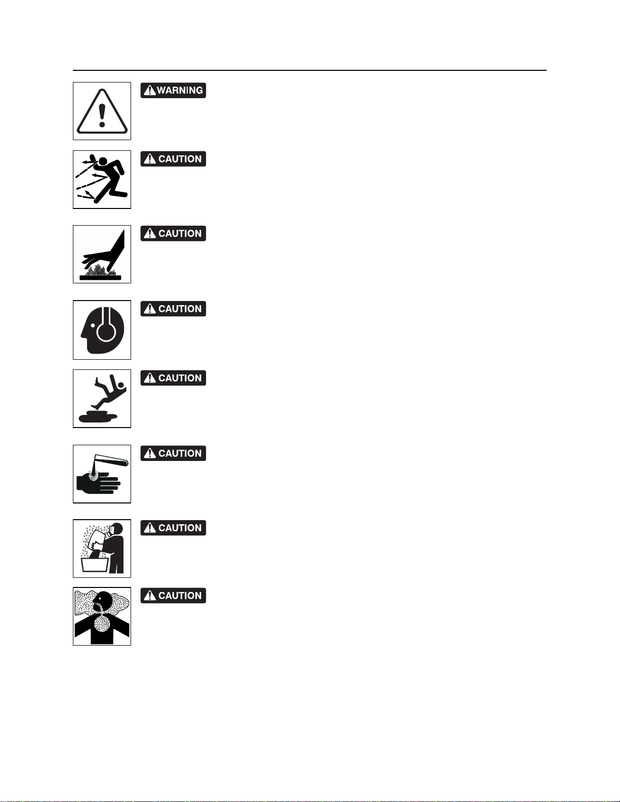
Safety Alerts
Safety Alerts
Turning shaft will kill you or crush arm or leg. Stay away.
Electric shock. Contacting electric lines will cause death or serious injury.
Know location of lines and stay away.
Moving tools will kill or injure. Shut off drill string power when anyone can be
struck by moving or thrown tools. Never use pipe wrenches on drill string.
correct equipment and work methods. Use and maintain proper safety
equipment.
proper procedures and equipment or stay away.
Explosion possible. Serious injury or equipment damage could occur.
Follow directions carefully.
Jobsite hazards could cause death or serious injury. Use
Crushing weight could cause death or serious injury. Use
Moving parts could cut off hand or foot. Stay away.
CMW®
Incorrect procedures could result in death, injury, or property damage.
Learn to use equipment correctly.

JT20 Operator’s Manual Safety - 15
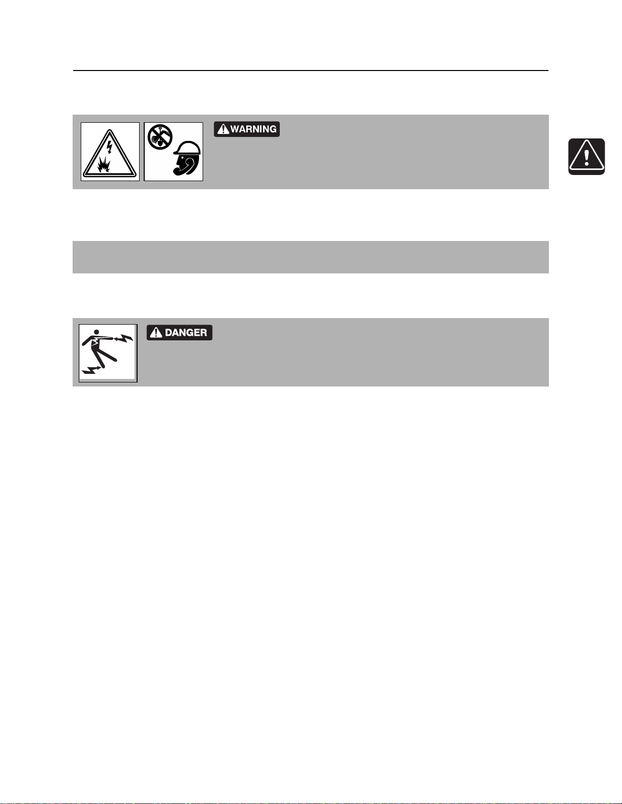
Safety Alerts
Improper control function could cause death or serious injury. If control does
not work as described in instructions, stop machine and have it serviced.
Looking into fiber optic cable could result in permanent vision damage. Do
not look into ends of fiber optic or unidentified cable.
Pressurized fluid or air could pierce skin and cause injury or
death. Stay away.
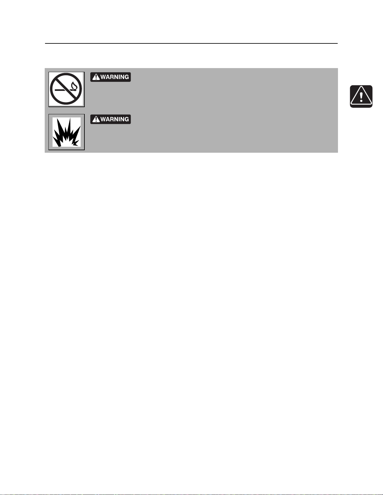
Fire or explosion possible. Fumes could ignite and cause burns. No
smoking, no flame, no spark.
Avoid static electricity when fueling. Ultra Low Sulfur Diesel (ULSD) poses a
greater static ignition hazard than earlier diesel formulations. Avoid death or serious injury
from fire or explosion. Consult with your fuel system supplier to ensure the delivery system
is in compliance with fueling standards for proper grounding and bonding practices.
Moving traffic - hazardous situation. Death or serious injury could result.
Avoid moving vehicles, wear high visibility clothing, post appropriate warning signs.
CMW®
Safety - 16 JT20 Operator’s Manual
Safety Alerts
Hot pressurized cooling system fluid could cause serious burns. Allow to
cool before servicing.
Flying objects may cause injury. Wear hard hat and safety glasses.
Hot parts may cause burns. Do not touch until cool.
Exposure to high noise levels may cause hearing loss. Wear hearing
protection.
Fall possible. Slips or trips may result in injury. Keep area clean.
Battery acid may cause burns. Avoid contact.
Improper handling or use of chemicals may result in illness, injury, or
equipment damage. Follow instructions on labels and in material safety data sheets
(MSDS).
Breathing crystalline silica dust may cause lung disease. Cutting, drilling, or
working materials such as concrete, sand, or rock containing quartz may result in exposure
to silica dust. Use dust control methods or appropriate breathing protection when exposed
to silica dust.
CMW®
JT20 Operator’s Manual Safety - 17
Emergency Procedures
Emergency Procedures
Jobsite hazards could cause death or serious injury. Use
correct equipment and work methods. Use and maintain proper safety
equipment.
Before operating any equipment, review emergency procedures and check that all safety precautions have
been taken.
EMERGENCY SHUTDOWN - Turn ignition switch to stop position or push remote engine stop button (if
equipped).
Electric Strike Description
Electric shock. Contacting electric lines will cause death or serious injury.
Know location of lines and stay away.
When working near electric cables, remember the following:
• Electricity follows all paths to ground, not just path of least resistance.
• Pipes, hoses, and cables will conduct electricity back to all equipment.
• Low voltage current can injure or kill. Many work-related electrocutions result from contact with less
than 440 volts.
Most electric strikes are not noticeable, but indications of a strike include:
• power outage
• smoke
• explosion
• popping noises
• arcing electricity
If any of these occur, or if strike alarm sounds or flashes, assume an electric strike has occurred.
CMW®

Safety - 18 JT20 Operator’s Manual
Emergency Procedures
If an Electric Line is Damaged
If you suspect an electric line has been damaged and you are on drilling unit or bonded equipment, DO
NOT MOVE. Remain on drilling machine and take the following actions. The order and degree of action will
depend on the situation.
• Warn people nearby that an electric strike has occurred.
• Have someone contact electric company.
• Reverse drilling direction and try to break contact. Do not touch drill pipe with hands or hand-held
tools.
• Press electric strike system self test button.
• If alarm sounds again, stay where you are and wait for electric company to shut off power.
• If alarm does not sound and there is no other indication of a strike, wait at least one full minute
before moving away from equipment. Utility might use automatic reclosers which will restart
current flow. If alarm sounds again while waiting, stay where you are until electric company shuts
off power.
• If alarm does not sound but all lights in strike indicator are on, assume strike is continuing and stay
where you are until electric company shuts off power.
• Do not resume drilling or allow anyone into area until given permission by electric company.
If you suspect an electric line has been damaged and you are off drilling unit or bonded equipment, DO
NOT TOUCH ANY EQUIPMENT connected to drilling unit. Take the following actions. The order and
degree of action will depend on the situation.
• Stay where you are unless you are wearing electric insulating boots. If you leave, do not return to area
or allow anyone into area until given permission by electric company.
CMW®
JT20 Operator’s Manual Safety - 19
Emergency Procedures
If a Gas Line is Damaged
Fire or explosion possible. Fumes could ignite and cause burns. No
smoking, no flame, no spark.
Explosion possible. Serious injury or equipment damage could occur.
Follow directions carefully.
If you suspect a gas line has been damaged, take the following actions. The order and degree of action will
depend on the situation.
• Immediately shut off engine(s), if this can be done safely and quickly.
• Remove any ignition source(s), if this can be done safely and quickly.
• Warn others that a gas line has been cut and that they should leave the area.
• Leave jobsite as quickly as possible.
• Immediately call your local emergency phone number and utility company.
• If jobsite is along street, stop traffic from driving near jobsite.
• Do not return to jobsite until given permission by emergency personnel and utility company.
CMW®

Safety - 20 JT20 Operator’s Manual
Emergency Procedures
If a Fiber Optic Cable is Damaged
Do not look into cut ends of fiber optic or unidentified cable. Vision damage can occur.
If Machine Catches on Fire
Perform emergency shutdown procedure and then take the following actions. The order and degree of
action will depend on the situation.
• Immediately move battery disconnect switch (if equipped and accessible) to disconnect position.
• If fire is small and fire extinguisher is available, attempt to extinguish fire.
• If fire cannot be extinguished, leave area as quickly as possible and contact emergency personnel.
CMW®

JT20 Operator’s Manual Operation Overview - 21
Operation Overview
Chapter Contents
Planning. . . . . . . . . . . . . . . . . . . . . . . . . . . . . . . . . . 22
Setting Up at Jobsite . . . . . . . . . . . . . . . . . . . . . . . 22
Drilling . . . . . . . . . . . . . . . . . . . . . . . . . . . . . . . . . . . 23
Backreaming . . . . . . . . . . . . . . . . . . . . . . . . . . . . . . 24
Leaving Jobsite. . . . . . . . . . . . . . . . . . . . . . . . . . . . 24
Storing Equipment . . . . . . . . . . . . . . . . . . . . . . . . . 24
CMW
®

Operation Overview - 22 JT20 Operator’s Manual
Planning
Planning
1. Gather information about jobsite. See page 61.
2. Inspect jobsite. See page 62.
3. Classify jobsite. See page 64.
4. Plan bore path. See page 66.
5. Check supplies and prepare equipment. See page 72.
6. Load equipment. See page 80.
Setting Up at Jobsite
1. Prepare jobsite. See page 71.
2. Unload drilling unit from trailer. See page 83.
3. Assemble drill string. See page 93.
4. Position drilling unit and drill frame. See page 89.
5. Assemble strike system. See page 113.
6. Anchor drilling unit. See page 111.
7. Connect fluid system. See page 89.
8. Calibrate tracker with beacon that will be installed in beacon housing. See tracker operator’s manual.
CMW
®

JT20 Operator’s Manual Operation Overview - 23
Drilling
Drilling
1. Start system. See page 90.
2. Engage tracker control if desired. See page 123.
3. Drill first pipe. See page 95.
4. Record bore path. See page 102.
5. Enable automated pipeloader system. See page 95.
6. Add pipe. See page 96.
7. Drill remaining pipes in pipe box.
• Correct direction. See page 98.
• Engage cruise control. See page 142.
• Shift pipe box. See page 137.
8. Add up to a single column of drill pipe to empty box (see page 137) to complete bore.
9. Surface drill head. See page 102.
CMW
®

Operation Overview - 24 JT20 Operator’s Manual
Backreaming
Backreaming
1. Assemble backream string. See page 104.
2. Start drilling unit and adjust throttle.See page 76.
3. Set drilling fluid flow. Check that fluid flows through all nozzles. See page 119.
4. Remove pipe from bore. See page 105.
5. Remove up to a single column of drill pipe from full box (see page 128) to complete backream.
6. Remove pullback device. See page 107.
Backreaming Tips
• Plan backreaming job before drilling. Plan bore path as straight as possible. Check bend limits of
pullback material. Check that appropriate pullback devices are on hand.
• Keep all bends as gradual as possible.
• Drilling fluid quality is a key factor in backreaming success. Contact your Ditch Witch® dealer for
information on testing water, selecting additives, and mixing drilling fluid.
• Backreaming requires more fluid than drilling. Make sure enough fluid is used.
Leaving Jobsite
1. Remove downhole tools. See page 107.
2. Remove anchors. See page 111.
3. Rinse unit and downhole tools. See page 154.
4. Disassemble strike system and disconnect from fluid system. See page 154.
5. Stow tools. See page 154.
6. Load unit onto trailer. See page 80.
Storing Equipment
1. For cold weather storage, antifreeze drilling unit. See page 152.
2. For long-term storage, disconnect battery disconnect switch.
CMW
®

JT20 Operator’s Manual Controls - 25
Controls
Chapter Contents
Set-Up Console . . . . . . . . . . . . . . . . . . . . . . . . . . . 26
Tethered Ground Drive Controller . . . . . . . . . . . . 29
Left Control Console . . . . . . . . . . . . . . . . . . . . . . . 31
• Engine Display . . . . . . . . . . . . . . . . . . . . . . . . . . . . . . . . . . . . . . . . . . . 31
• Pipeloading controls . . . . . . . . . . . . . . . . . . . . . . . . . . . . . . . . . . . . . . . 37
• Drilling/Operation controls . . . . . . . . . . . . . . . . . . . . . . . . . . . . . . . . . . 41
Right Control Console . . . . . . . . . . . . . . . . . . . . . . 46
Anchoring System Console . . . . . . . . . . . . . . . . . 48
Seat/Armrest . . . . . . . . . . . . . . . . . . . . . . . . . . . . . . 50
Battery . . . . . . . . . . . . . . . . . . . . . . . . . . . . . . . . . . . 52
ESID . . . . . . . . . . . . . . . . . . . . . . . . . . . . . . . . . . . . . 53
CMW
®
Controls - 26 JT20 Operator’s Manual
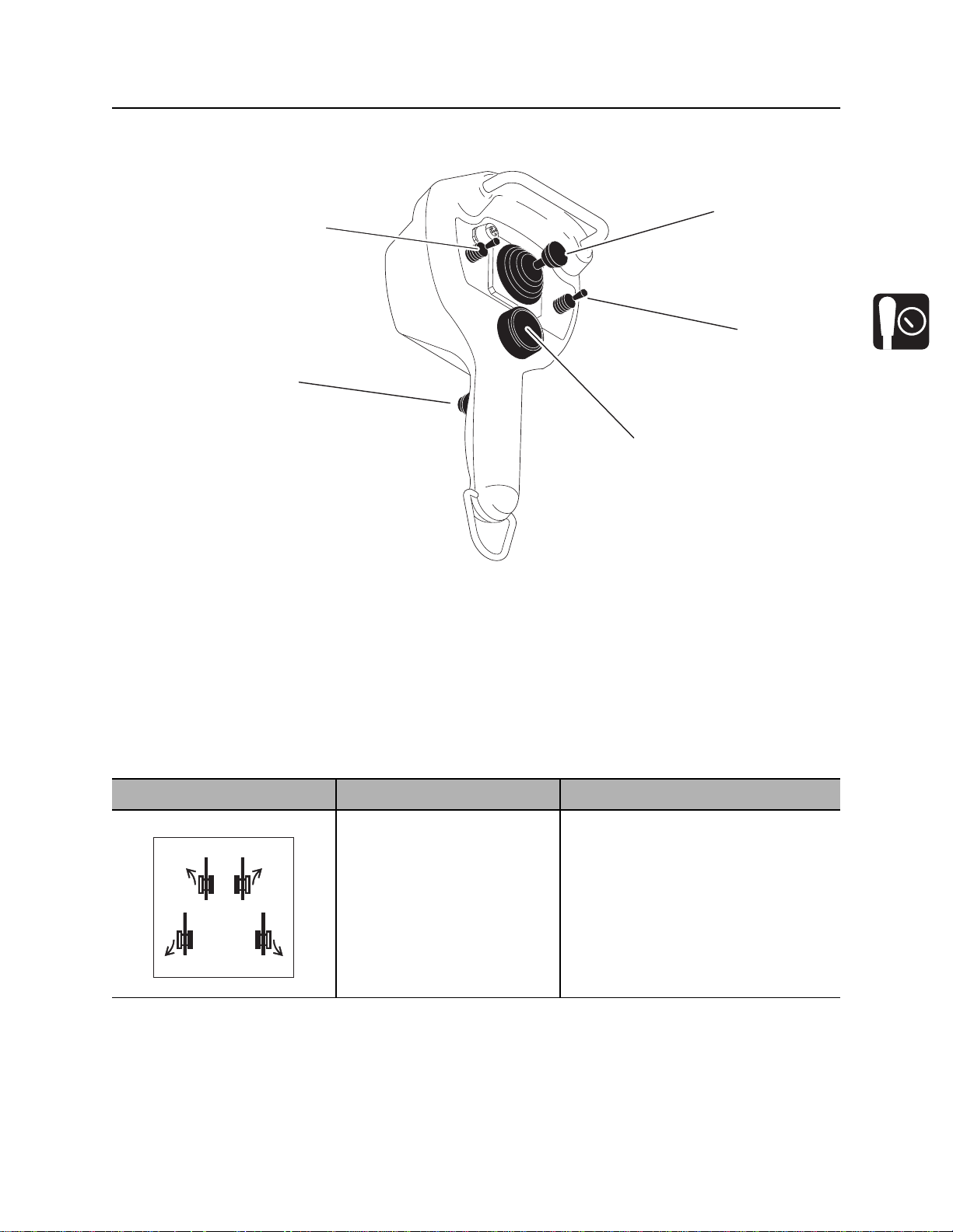
Set-Up Console
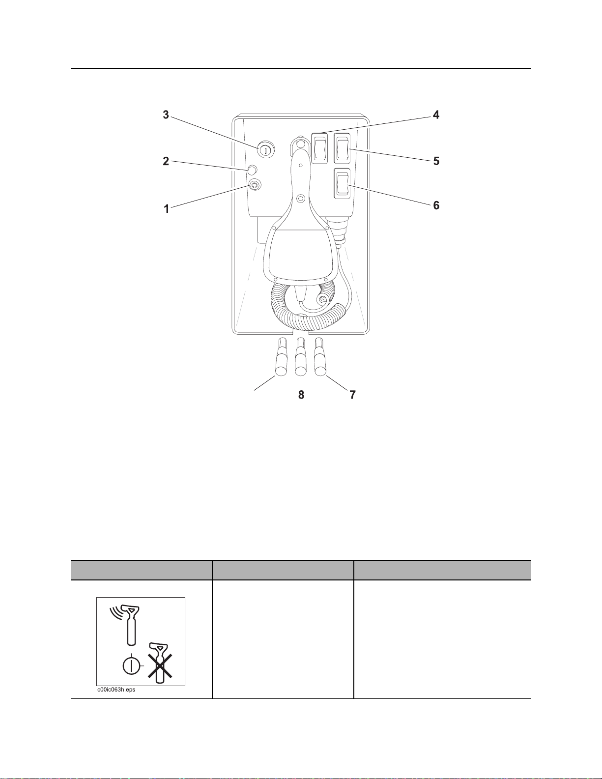
Set-Up Console
j38om039w.eps
9
1. Tracker control key
2. Cold start wait indicator
3. Ignition switch
4. Left track switch
5. Right track switch
Item Description Notes
1. Tracker control key To allow tracker operator to
stop thrust and rotation, move
key to enable position (up).
To override tracker control
mode, move key to disable
position (right).
6. Engine shutdown override switch
7. Right stabilizer control
8. Frame tilt control
9. Left stabilizer control
Remove key and keep in tracker
operator’s possession.
CMW
®

JT20 Operator’s Manual Controls - 27
Set-Up Console
Item Description Notes
2. Cold start wait indicator Lights when intake air pre-
heater is operating.
Wait until light goes off before
starting engine.
3. Ignition switch To start engine, insert key and
turn clockwise.
To stop engine, turn key
counterclockwise.
4. Left track switch To move forward, press top.
To move backward, press
bottom.
c00ic147h.eps
5. Right track switch To move forward, press top.
To move backward, press
bottom.
Restart engine with ignition switch
after it has been turned off with
remote engine stop switch.
If wrenches are engaged when
engine is stopped with ignition switch,
wrenches will release and then
engage when unit is started.
Use track switches only if tethered
control is inoperable.
Use track switches only if tethered
control is inoperable.
c00ic148h.eps
6. Engine shutdown
override switch
c00ic178h.eps
If engine shutdown indicator
comes on, press to delay
engine shutdown for 30
seconds.
This control allows a temporary
override of engine shutdown.
NOTICE: After 30 seconds, engine
will again shut down unless fault
condition has been cleared on
diagnostic gauge. See “Electronic
Controlled Engine Overview” on
page 144.
CMW
®

Controls - 28 JT20 Operator’s Manual
Set-Up Console
Item Description Notes
7. Right stabilizer control To raise, pull up.
To lower, push down.
8. Frame tilt control To raise front end of drill
frame, pull up.
To lower front end of drill
frame, push down.
9. Left stabilizer control To raise, pull up.
To lower, push down.
Lower left and right stabilizers to the
ground to stabilize unit and then
adjust for side-to-side stability. After
unit is level, adjust for entry angle.
Lower left and right stabilizers to the
ground to stabilize unit and then
adjust for side-to-side stability. After
unit is level, adjust for entry angle.
CMW
®
JT20 Operator’s Manual Controls - 29
Tethered Ground Drive Controller
Tethered Ground Drive Controller
1
5
2
4
3
j10om016h.eps
1. Speed/direction control
2. Power mode switch
3. Remote engine stop
Item Description Notes
1. Speed/direction control To move forward, push.
To move backward, pull.
To steer, move left or right.
c00ic145h.eps
4. Operator presence switch
5. Throttle switch
Operator presence switch must be
pressed and operator seat must be
empty for control to work.
CMW
®
 Loading...