

Page 1

JT100/JT100 All Terrain
Operator’s
Manual
CMW
®
Issue 1.0
Original Instruction
053-2546
Page 2

JT100/JT100 All Terrain Operator’s Manual Overview - 1
Overview
Chapter Contents
Serial Number Location . . . . . . . . . . . . . . . . . . . . . . 2
Intended Use . . . . . . . . . . . . . . . . . . . . . . . . . . . . . . 3
Equipment Modification . . . . . . . . . . . . . . . . . . . . . 3
Unit Components . . . . . . . . . . . . . . . . . . . . . . . . . . . 4
Operator Orientation . . . . . . . . . . . . . . . . . . . . . . . . 4
About This Manual . . . . . . . . . . . . . . . . . . . . . . . . . . 4
• Bulleted Lists . . . . . . . . . . . . . . . . . . . . . . . . . . . . . . . . . . . . . . . . . . . . . 5
• Numbered Lists . . . . . . . . . . . . . . . . . . . . . . . . . . . . . . . . . . . . . . . . . . . 5
• “Continued” Indicators . . . . . . . . . . . . . . . . . . . . . . . . . . . . . . . . . . . . . . 5
CMW
©
Page 3
Overview - 2 JT100/JT100 All Terrain Operator’s Manual
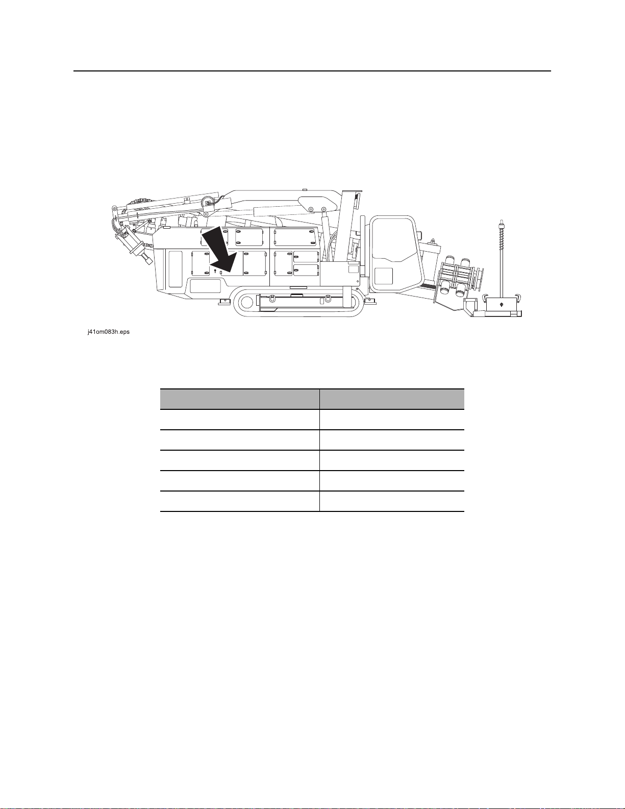
Serial Number Location
Serial Number Location
Record serial numbers and date of purchase in spaces provided. Drilling unit serial number is located as
shown.
Item
date of manufacture
date of purchase
drilling unit serial number
driver/loader serial number
engine serial number
CMW
©
Page 4

JT100/JT100 All Terrain Operator’s Manual Overview - 3
Intended Use
Intended Use
The JT100/JT100 All Terrain is a self-contained horizontal directional drilling unit capable of drilling and
backreaming through solid rock, cobblestone, broken rock, gravel, and other soil/rock mixes, as well as
less extreme soil conditions. It is designed to install buried cable and pipe at distances to 2,000’ (610 m)
depending on soil conditions and is intended for operation in ambient temperatures from 0° to 115°F (-18°
to 46°C). Use in any other way is considered contrary to the intended use.
The unit can be used with Ditch Witch drilling fluid units and Ditch Witch
operated, serviced, and repaired only by persons familiar with its particular characteristics and acquainted
with the relevant safety procedures.
®
tracking equipment. It should be
Equipment Modification
This equipment was designed and built in accordance with applicable standards and regulations.
Modification of equipment could mean that it will no longer meet regulations and may not function properly
or in accordance with the operating instructions. Modification of equipment should only be made by
competent personnel possessing knowledge of applicable standards, regulations, equipment design
functionality/requirements and any required specialized testing.
CMW
©
Page 5
Overview - 4 JT100/JT100 All Terrain Operator’s Manual
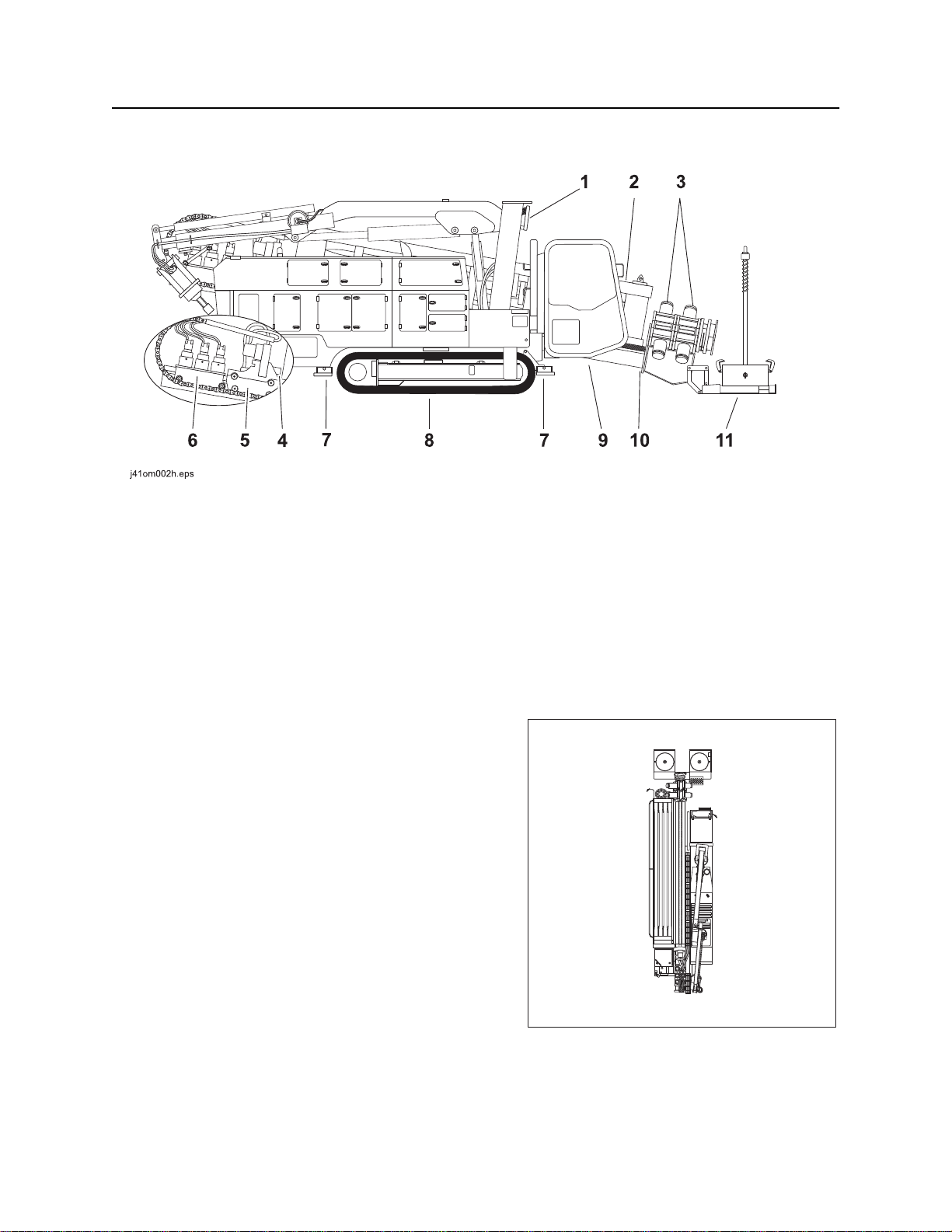
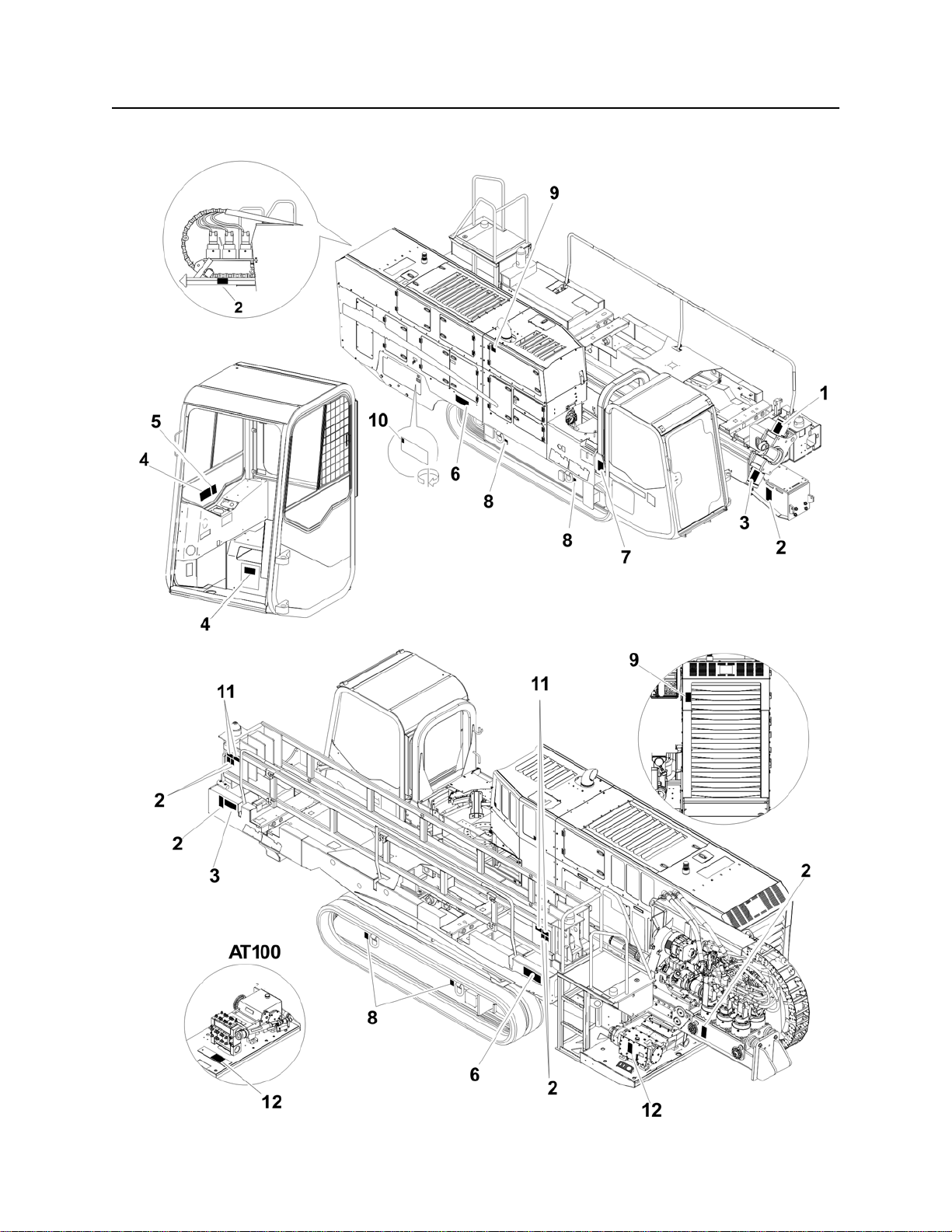
Unit Components
Unit Components
1. Driver/loader attachment (optional)
2. Pipeloader
3. Front and rear wrenches
4. Spindle
5. Rotation carriage
6. Thrust carriage
Operator Orientation
1. Front of unit
2. Right side of unit
3. Rear of unit
4. Left side of unit
7. Front and rear stabilizers
8. Tracks
9. Operator’s station
10. Drill frame
11. Anchoring system (optional)
1
4
2
CMW
3
j28om097t.eps
©
Page 6

JT100/JT100 All Terrain Operator’s Manual Overview - 5
About This Manual
About This Manual
This manual contains information for the proper use of this machine. See the beige Operation Overview
pages for basic operating procedures. Cross references such as “See page 50” will direct you to detailed
procedures.
Bulleted Lists
Bulleted lists provide helpful or important information or contain procedures that do not have to be
performed in a specific order.
Numbered Lists
Numbered lists contain illustration callouts or list steps that must be performed in order.
“Continued” Indicators
indicates that a procedure is continued on the next page.
CMW
©
Page 7

Overview - 6 JT100/JT100 All Terrain Operator’s Manual
CMW
©
Page 8

JT100/JT100 All Terrain Operator’s Manual Foreword - 7
Foreword
This manual is an important part of your equipment. It provides safety information and operation
instructions to help you use and maintain your Ditch Witch
Read this manual before using your equipment. Keep it with the equipment at all times for future reference.
If you sell your equipment, be sure to give this manual to the new owner.
If you need a replacement copy, contact your Ditch Witch dealer. If you need assistance in locating a
dealer, visit our website at www.ditchwitch.com or write to the following address:
The Charles Machine Works, Inc.
Attn: Marketing Department
PO Box 66
Perry, OK 73077-0066
USA
The descriptions and specifications in this manual are subject to change without notice. The Charles
Machine Works, Inc. reserves the right to improve equipment. Some product improvements may have
taken place after this manual was published. For the latest information on Ditch Witch equipment, see your
Ditch Witch dealer.
®
equipment.
Thank you for buying and using Ditch Witch equipment.
CMW
©
Page 9

Foreword - 8 JT100/JT100 All Terrain Operator’s Manual
JT100/JT100 All Terrain
(Tier 4i)
Operator’s Manual
Issue number 1.0/OM-3/14
Part number 053-2546
Copyright 2014
by The Charles Machine Works, Inc.
, Ditch Witch, Jet Trac, Fluid Miser, Power Pipe, and CMW are registered
trademarks of The Charles Machine Works, Inc.
This product is covered by one or more of the following patents:
US 5,490,569; 5,684,466; 5,740,703; 5,758,553; 5,794,719; 5,880,680; 6,085,852C1; 6,109,371; 6,179,065; 6,250,403; 6,250,404;
6,311,790; 6,411,094; 6,543,551; 6,550,547; 6,672,409; 6,739,413; 6,761, 231; 6,808,210; 6,827,158; 6,848,506; 6, 871,712;
7,011,166; 7,018,164; 7, 025,152; 7, 038,454; 7,240,742; 7,347,283; 7,392,858; 7,413,031; 7,600,584; 7,628,226; 7,759,824;
7,987,924; 8,201,644; 8,534,388; RE38,418; CA 2,156,398; 2,217,899; DE 603 04 320; 694 17 019; 695 29 633; 697 28 716; 698 29
107; 197 12 641; FR 674,093; GB 2,312,006; UK0674093; UK0984132; UK1466068; UK817901; EP927892; JP 3,458,247; other
U.S. and foreign patents pending.
CMW
©
Page 10
JT100/JT100 All Terrain Operator’s Manual Contents - 9
Contents
Overview
machine serial number, information about the type of work this machine is designed
to perform, basic machine components, and how to use this manual
Foreword
part number, revision level, and publication date of this manual, and factory contact
information
Safety
machine safety alerts and emergency procedures
Controls
machine controls, gauges, and indicators and how to use them
Operation Overview
an overview for completing a job with this machine: planning, setting up, installing
product, and restoring the jobsite; with cross references to detailed procedures
Prepare
procedures for inspecting and classifying the jobsite, planning the installation path,
and preparing the jobsite for work
Drive
procedures for startup, cold start, driving, and shutdown
1
7
11
27
71
75
101
Transport
procedures for lifting, hauling, and towing
Conduct a Bore
procedures for drilling and backreaming
Systems and Equipment
downhole tools and drill pipe, anchor, electric strike, tracker control, and fluid
systems
Complete the Job
procedures for backfilling and restoring the jobsite and rinsing and storing
equipment
Service
service intervals and instructions for this machine including lubrication, replacement
of wear items, and basic maintenance
105
111
133
179
185
CMW
©
Page 11

Contents - 10 JT100/JT100 All Terrain Operator’s Manual
Specifications
machine specifications including weights, measurements, power ratings, and fluid
capacities
Support
the warranty policy for this machine, and procedures for obtaining warranty
consideration and training
Service Record
a record of major service performed on the machine
231
239
237
CMW
©
Page 12

JT100/JT100 All Terrain Operator’s Manual Safety - 11
Safety
Chapter Contents
Guidelines . . . . . . . . . . . . . . . . . . . . . . . . . . . . . . . . 12
Emergency Procedures . . . . . . . . . . . . . . . . . . . . . 13
• Electric Strike Description. . . . . . . . . . . . . . . . . . . . . . . . . . . . . . . . . . . 13
• If an Electric Line is Damaged . . . . . . . . . . . . . . . . . . . . . . . . . . . . . . . 14
• If a Gas Line is Damaged . . . . . . . . . . . . . . . . . . . . . . . . . . . . . . . . . . . 15
• If a Fiber Optic Cable is Damaged . . . . . . . . . . . . . . . . . . . . . . . . . . . . 16
• If Machine Catches on Fire. . . . . . . . . . . . . . . . . . . . . . . . . . . . . . . . . . 16
Safety Alert Classifications . . . . . . . . . . . . . . . . . . 21
Machine Safety Alerts . . . . . . . . . . . . . . . . . . . . . . 22
Attachment Safety Alerts . . . . . . . . . . . . . . . . . . . 25
CMW
©
Page 13

Safety - 12 JT100/JT100 All Terrain Operator’s Manual
Guidelines
Guidelines
Follow these guidelines before operating any jobsite equipment:
• Complete proper training and read operator’s manual before using equipment.
• Contact your local One-Call (811 in USA) or the One-Call referral number (888-258-0808 in USA and
Canada) to have underground utilities located before digging. Also contact any utilities that do not
participate in the One-Call service. Mark proposed path with white paint prior to contacting One-Call or
utilities.
• Classify jobsite based on its hazards and use correct tools and machinery, safety equipment, and work
methods for jobsite.
• Mark jobsite clearly and keep spectators away.
• Wear personal protective equipment.
• Review jobsite hazards, safety and emergency procedures, and individual responsibilities with all
personnel before work begins. Safety videos are available from your Ditch Witch
• Replace missing or damaged safety shields and safety signs.
• Use equipment carefully. Stop operation and investigate anything that does not look or feel right.
®
dealer.
• Do not operate unit where flammable gas may be present.
• Contact your Ditch Witch dealer if you have any question about operation, maintenance, or equipment
use.
• Complete the equipment checklist located at www.ditchwitch.com/resources/safety.
CMW
©
Page 14
JT100/JT100 All Terrain Operator’s Manual Safety - 13
Emergency Procedures
Emergency Procedures
Jobsite hazards could cause death or serious injury. Use
correct equipment and work methods. Use and maintain proper safety
equipment.
Before operating any equipment, review emergency procedures and check that all safety precautions have
been taken.
EMERGENCY SHUTDOWN - Turn ignition switch to stop position or push remote engine stop button (if
equipped).
Electric Strike Description
Electric shock. Contacting electric lines will cause death or serious injury.
Know location of lines and stay away.
When working near electric cables, remember the following:
• Electricity follows all paths to ground, not just path of least resistance.
• Pipes, hoses, and cables will conduct electricity back to all equipment.
• Low voltage current can injure or kill. Many work-related electrocutions result from contact with less
than 440 volts.
Most electric strikes are not noticeable, but indications of a strike include:
• power outage
• smoke
• explosion
• popping noises
• arcing electricity
If any of these occur, or if strike alarm sounds or flashes, assume an electric strike has occurred.
CMW
©
Page 15

Safety - 14 JT100/JT100 All Terrain Operator’s Manual
Emergency Procedures
If an Electric Line is Damaged
If you suspect an electric line has been damaged and you are on drilling unit or bonded equipment, DO
NOT MOVE. Remain on drilling machine and take the following actions. The order and degree of action will
depend on the situation.
• Warn people nearby that an electric strike has occurred.
• Have someone contact electric company.
• Reverse drilling direction and try to break contact. Do not touch drill pipe with hands or hand-held
tools.
• Press electric strike system self test button.
• If alarm sounds again, stay where you are and wait for electric company to shut off power.
• If alarm does not sound and there is no other indication of a strike, wait at least one full minute
before moving away from equipment. Utility might use automatic reclosers which will restart
current flow. If alarm sounds again while waiting, stay where you are until electric company shuts
off power.
• If alarm does not sound but all lights in strike indicator are on, assume strike is continuing and stay
where you are until electric company shuts off power.
• Do not resume drilling or allow anyone into area until given permission by electric company.
If you suspect an electric line has been damaged and you are off drilling unit or bonded equipment, DO
NOT TOUCH ANY EQUIPMENT connected to drilling unit. Take the following actions. The order and
degree of action will depend on the situation.
• Stay where you are unless you are wearing electric insulating boots. If you leave, do not return to area
or allow anyone into area until given permission by electric company.
CMW
©
Page 16
JT100/JT100 All Terrain Operator’s Manual Safety - 15
Emergency Procedures
If a Gas Line is Damaged
Fire or explosion possible. Fumes could ignite and cause
burns. No smoking, no flame, no spark.
Explosion possible. Serious injury or equipment damage could occur.
Follow directions carefully.
If you suspect a gas line has been damaged, take the following actions. The order and degree of action will
depend on the situation.
• Immediately shut off engine(s), if this can be done safely and quickly.
• Remove any ignition source(s), if this can be done safely and quickly.
• Warn others that a gas line has been cut and that they should leave the area.
• Leave jobsite as quickly as possible.
• Immediately call your local emergency phone number and utility company.
• If jobsite is along street, stop traffic from driving near jobsite.
• Do not return to jobsite until given permission by emergency personnel and utility company.
CMW
©
Page 17

Safety - 16 JT100/JT100 All Terrain Operator’s Manual
Emergency Procedures
If a Fiber Optic Cable is Damaged
Do not look into cut ends of fiber optic or unidentified cable. Vision damage can occur. Contact utility
company.
If Machine Catches on Fire
Perform emergency shutdown procedure and then take the following actions. The order and degree of
action will depend on the situation.
• Immediately move battery disconnect switch (if equipped and accessible) to disconnect position.
• If fire is small and fire extinguisher is available, attempt to extinguish fire.
• If fire cannot be extinguished, leave area as quickly as possible and contact emergency personnel.
CMW
©
Page 18

JT100/JT100 All Terrrain Operator’s Manual Safety - 17
Driver/Loader Precautions
Driver/Loader Precautions
Intended Use
The driver/loader is to be used for driving anchors and loading and unloading pipe boxes only. Use in any
other way is considered contrary to the intended use.
Preparation
Visually inspect driver/loader each day to determine that it is in good condition before it is used. Check the
following:
• Make sure driver/loader is free of excess oil, grease, mud and debris before operation.
• Test driver/loader at the beginning of each shift to determine that the operating systems are in good
working order.
• Check safety devices to ensure they are functioning and in place.
• Check boom, hoses and connecting pins for wear and damage.
Transportation
• Always store auxiliary stabilizer before moving unit.
• Always store driver/loader properly for transportation.
• Never drive with load suspended from driver/loader.
Jobsite Setup
• Always use unit stabilizers during driver/loader operation. Ensure that they are firmly positioned on
solid footings.
• Always install auxiliary stabilizer for driver/loader operation on engine side of unit.
• If auxiliary stabilizer rests on curb or other object that prevents it from supporting load, consider
blocking under the arm of the auxiliary stabilizer as near the outer end as possible to support load.
• If auxiliary stabilizer does not rest on ground due to holes or grades, it must be blocked up to provide
level and firm support for the unit.
• When working in soft soil conditions, use wide pad under auxiliary stabilizer foot to prevent sinking.
• Ensure loads are securely attached before lifting.
CMW
©
Page 19
Safety - 18 JT100/JT100 All Terrrain Operator’s Manual
Driver/Loader Precautions
Operation
General
Riding on boom or load will result in death or serious
injury. No riders. Keep off.
• Never place chain link on tip of hook to lift load.
• Close hook throat before lifting load.
• Never use a sling bar or anything larger than the hook throat that could prevent hook latch from
closing. This prevents damage to material being hoisted and helps prevent injury to personnel.
• No unqualified or unauthorized person shall be allowed to operate the loader/driver.
• Always comply with load chart capacities. Weight of heavy load can create enough tipping momentum
to overturn drilling unit.
• Observe operating area obstructions or power lines that might be a hazard.
• Keep objects and personnel clear of driver/loader path during operation.
• Do not take your eyes off a moving load. Always look in the direction load is moving.
©
CMW
Page 20
JT100/JT100 All Terrrain Operator’s Manual Safety - 19
Driver/Loader Precautions
• Never swing a load over people.
• Consider overall height of unit when moving under objects with low overhead clearance.
• Operate controls smoothly and do not stop load sharply in midair so that it swings.
• Fluid pressure from broken hydraulic line could pierce skin and cause injury or death. Stay away.
• Keep loader/driver boom length as short as possible for maximum lifting capacity and safety. Longer
booms require additional care in accelerating and decelerating the swing motion and thus slow down
the working cycle and reduce production.
• Never use loader/driver for towing or pulling a load sideways. Keep load directly under boom point at
all times. Boom can fail far below its rated capacity if the driver/loader is side loaded.
• Always walk around unit and check for obstructions before moving load.
• Do not lift personnel with driver/loader.
• Know weight of rigging and load to avoid overloading driver/loader.
• Heavy loads can create enough tipping movement to overturn vehicle. Always install auxiliary stabilizer
when lifting on the engine side of unit.
• Except for anchoring drilling unit, do not apply down force with boom extensions, lift, or outer boom
function.
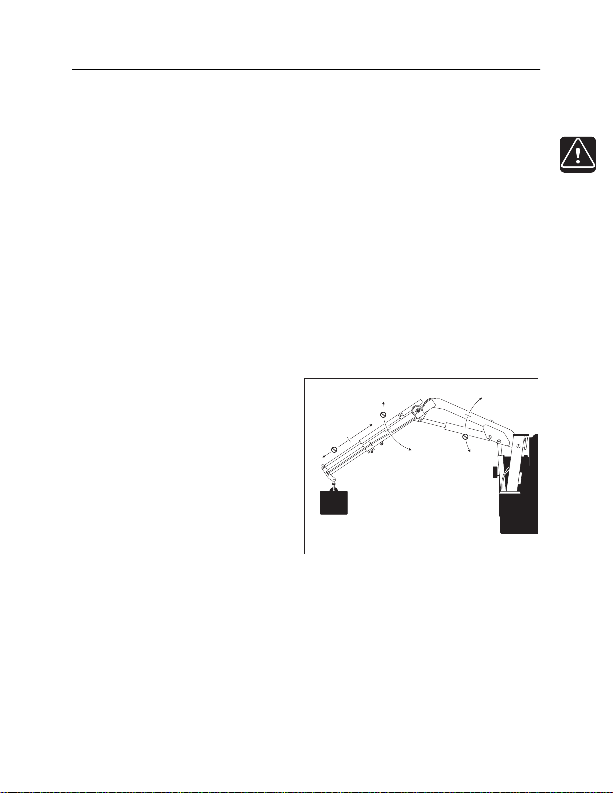
Driver/Loader Overload
If driver/loader becomes overloaded, driver/
loader components will not move in some
directions (see illustration) until overload
condition is overcome.
• Bring load closer to unit to overcome
overload.
• Confirm load before continuing.
j28om133t.eps
CMW
©
Page 21
Safety - 20 JT100/JT100 All Terrrain Operator’s Manual
Driver/Loader Precautions
Near Electrical Power Lines
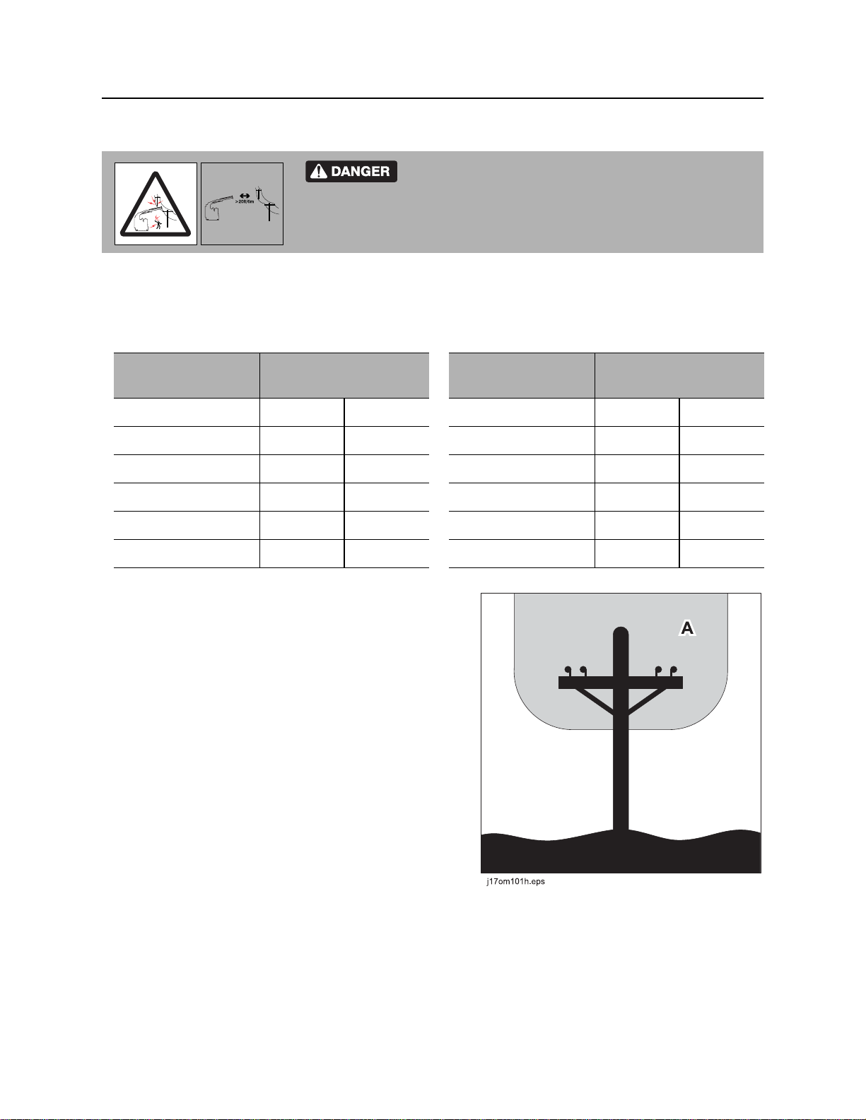
Do not get boom near power lines. Death or serious
injury will occur. Keep required distance between boom and power lines.
Use a spotter.
Never operate the driver/loader within 10’ (3 m) of electric power lines carrying up to 50 kV. Add 1’ (305
mm) of clearance for each additional 30 kV or less (see table on left). Follow OSHA or other guidelines for
working around power lines. Also observe minimum clearance requirements during transport (see table on
right).
Normal voltage
(phase to phase)
up to 50 kV 10’ 3 m
51-200 kV 15’ 4.6 m
201-350 kV 20’ 6 m
351-500 kV 25’ 7.6 m
501-750 kV 35’ 10.7 m
751-1000 kV 45’ 13.7 m
Do not enter the danger zone (A), unless one of the
following conditions is met:
• An appointed person has confirmed that the electrical
distribution and transmission lines have been deenergized and visibly grounded at the point of work.
• Insulating barriers (not a part of the attachment or
driver/loader) have been erected to prevent physical
contact with the lines.
Minimum operating
clearance required
Normal voltage
(phase to phase)
up to 0.75 kV 4’ 1.2 m
0.76-200 kV 6’ 1.8 m
50-345 kV 10’ 3.8 m
346-750 kV 16’ 4.9 m
751-1000 kV 20’ 6.1 m
unknown 20’ 6.1 m
Minimum transporting
clearance required
Maintenance
• Before working on the driver/loader, lower boom to
the ground, turn driver/loader controls off and relieve
hydraulic pressure from circuits.
• Never weld, modify, or use unauthorized components
on driver/loader attachment. This will void any
warranty or liability, and driver/loader failure could result.
• Check hook before each use for distortions or cracks.
• Stop all operations when cleaning, adjusting or lubricating the machine.
• Install all guards before returning driver/loader to service.
©
CMW
Page 22

JT100/JT100 All Terrrain Operator’s Manual Safety - 21
Safety Alert Classifications
Safety Alert Classifications
These classifications and the icons defined on the following pages work together to alert you to situations
which could be harmful to you, jobsite bystanders or your equipment. When you see these words and
icons in the book or on the machine, carefully read and follow all instructions. YOUR SAFETY IS AT
STAKE.
Watch for the three safety alert levels: DANGER, WARNING and CAUTION. Learn what each level
means.
indicates a hazardous situation that, if not avoided, will result in death or serious injury. This
signal word is to be limited to the most extreme situations.
indicates a hazardous situation that, if not avoided, could result in death or serious injury.
indicates a hazardous situation that, if not avoided, could result in minor or moderate injury.
Watch for two other words: NOTICE and IMPORTANT.
NOTICE indicates information considered important, but not hazard-related (e.g., messages relating to
property damage).
IMPORTANT can help you do a better job or make your job easier in some way.
CMW
©
Page 23
Safety - 22 JT100/JT100 All Terrrain Operator’s Manual
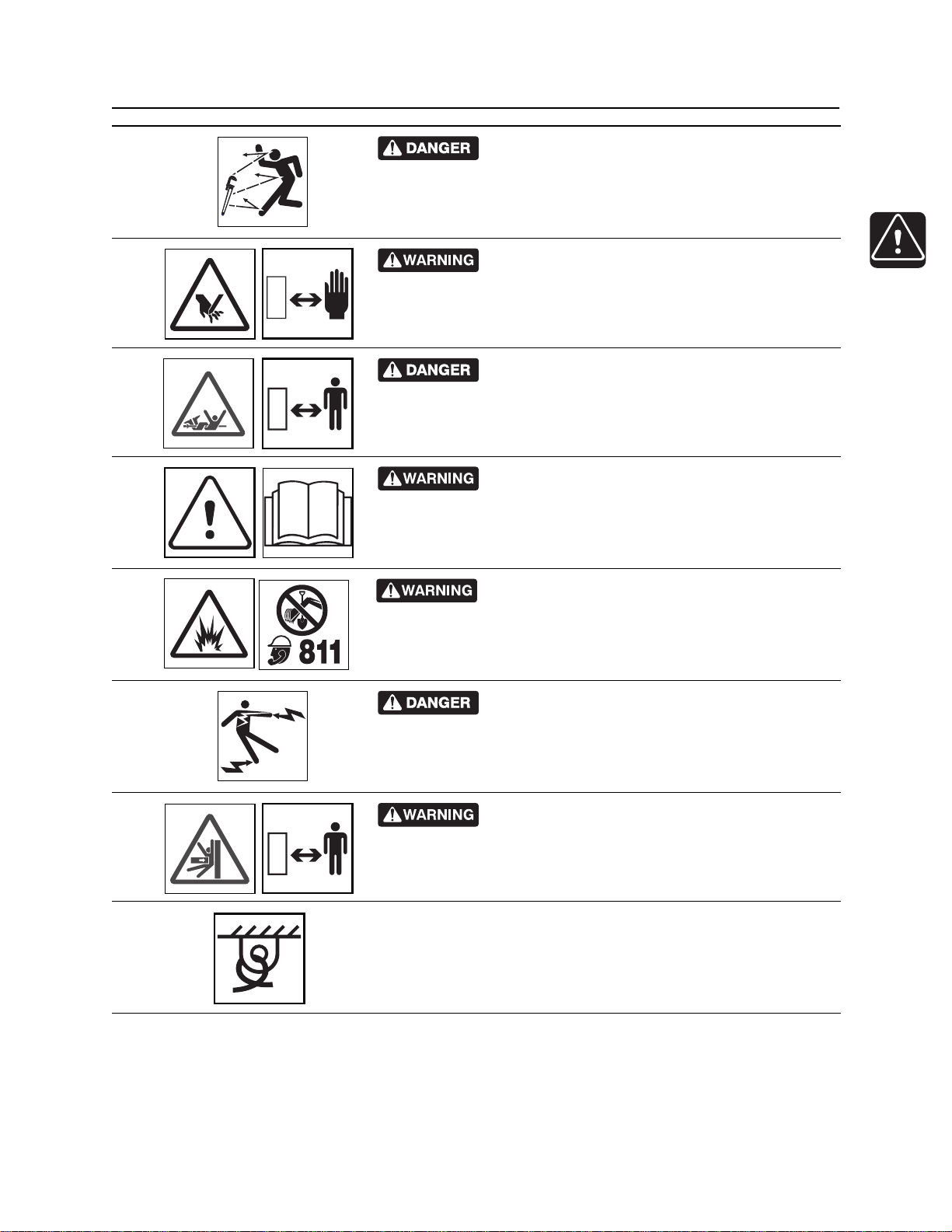
Machine Safety Alerts
Machine Safety Alerts
CMW
©
Page 24
JT100/JT100 All Terrrain Operator’s Manual Safety - 23
Machine Safety Alerts
Moving tools will kill or injure. Shut off drill string
1
2
3
4
power when anyone can be struck by moving or thrown tools.
Never use pipe wrenches on drill string.
Moving parts could cut off hand. Keep hands away.
Turning shaft will kill you or crush arm or leg. Stay
away.
Read operator’s manual. Know how to use all
controls. Your safety is at stake.
Jobsite hazards could cause death or serious
5
6
7
8
injury. Use correct equipment and work methods. Use and maintain
proper safety equipment.
Electric shock will cause death or serious injury.
Disconnect all power to this equipment before servicing.
Crushing weight could cause death or serious
injury. Use proper procedures and equipment or stay away.
Tiedown location. See Transport chapter for more information.
CMW
©
Page 25
Safety - 24 JT100/JT100 All Terrrain Operator’s Manual
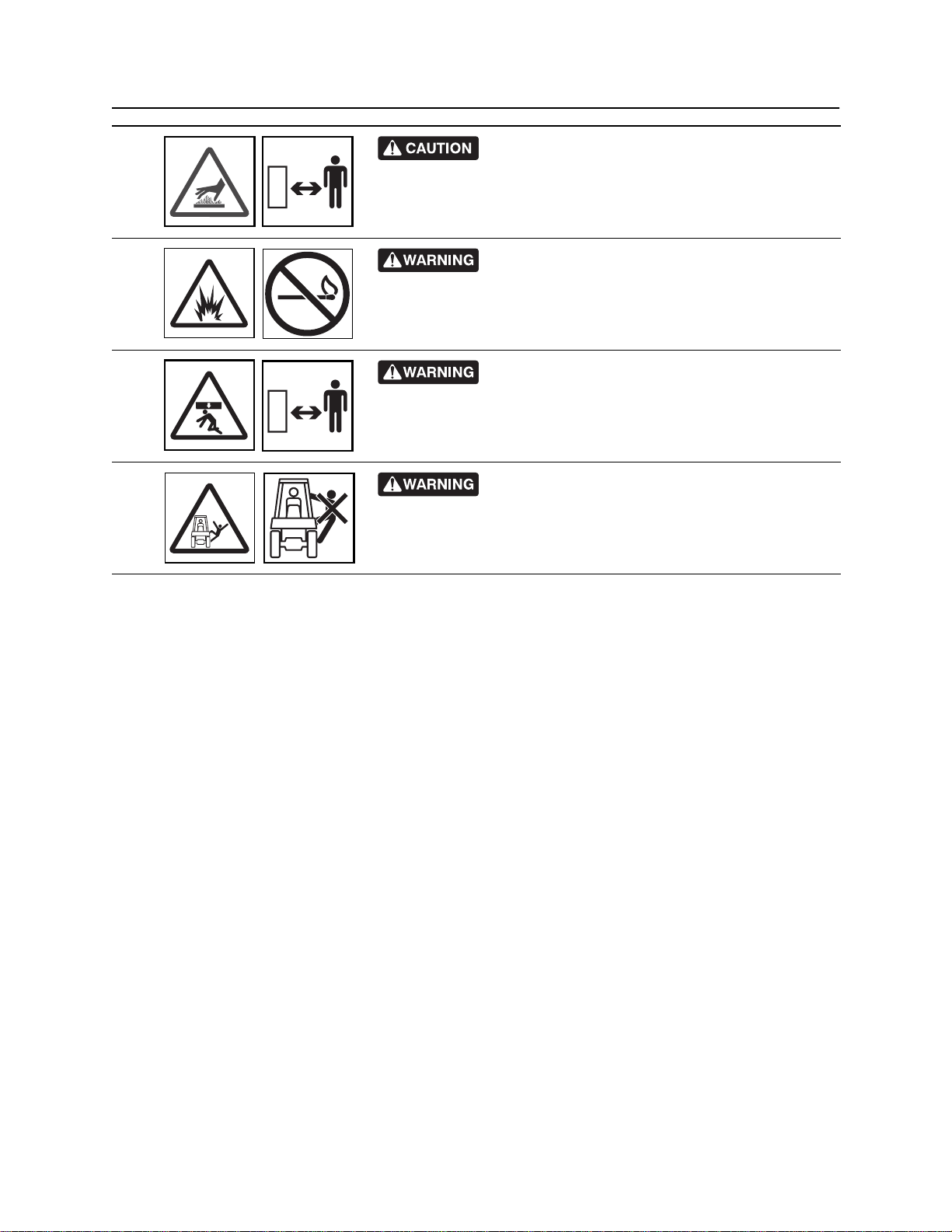
Machine Safety Alerts
Hot parts may cause burns. Do not touch until cool
9
10
11
12
or wear gloves.
Fire or explosion possible. Fumes could ignite and
cause burns. No smoking, no flame, no spark.
Crushing weight could cause death or serious
injury. Use proper procedures and equipment or stay away.
Fall possible. Riders can fall from machine and be
injured or killed. Only operator is allowed on machine.
CMW
©
Page 26
JT100/JT100 All Terrrain Operator’s Manual Safety - 25
Attachment Safety Alerts
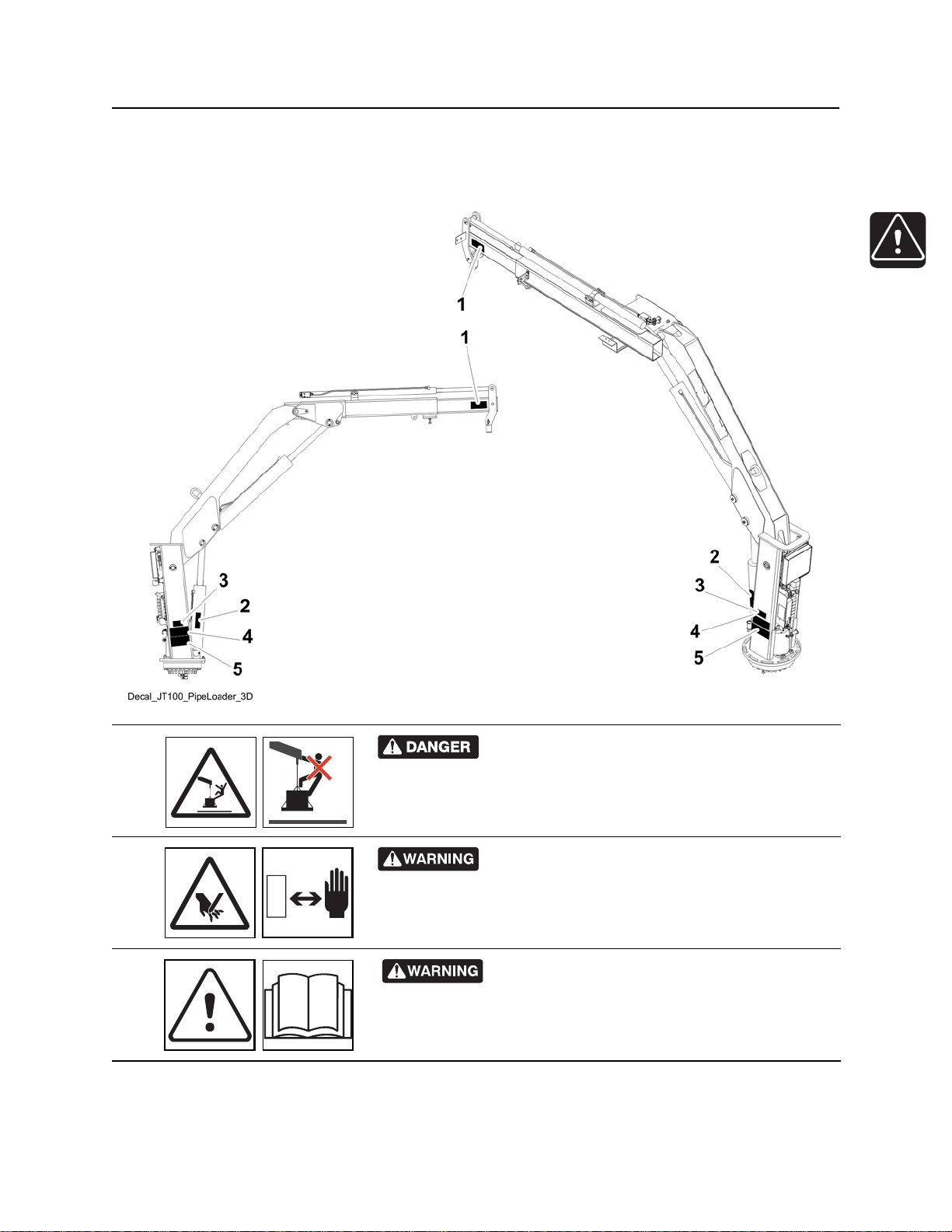
Attachment Safety Alerts
Driver/Loader Attachment
Riding on boom or load will result in death or
1
2
3
serious injury. No riders. Keep off.
Moving parts could cut off hand. Keep hands away.
Read operator’s manual. Know how to use all
controls. Your safety is at stake.
CMW
©
Page 27
Safety - 26 JT100/JT100 All Terrrain Operator’s Manual
Attachment Safety Alerts
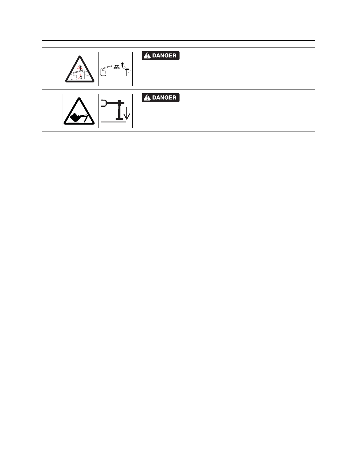
Do not get boom near power lines. Death or
4
5
serious injury will occur. Keep required distance between boom
and power lines. Use a spotter.
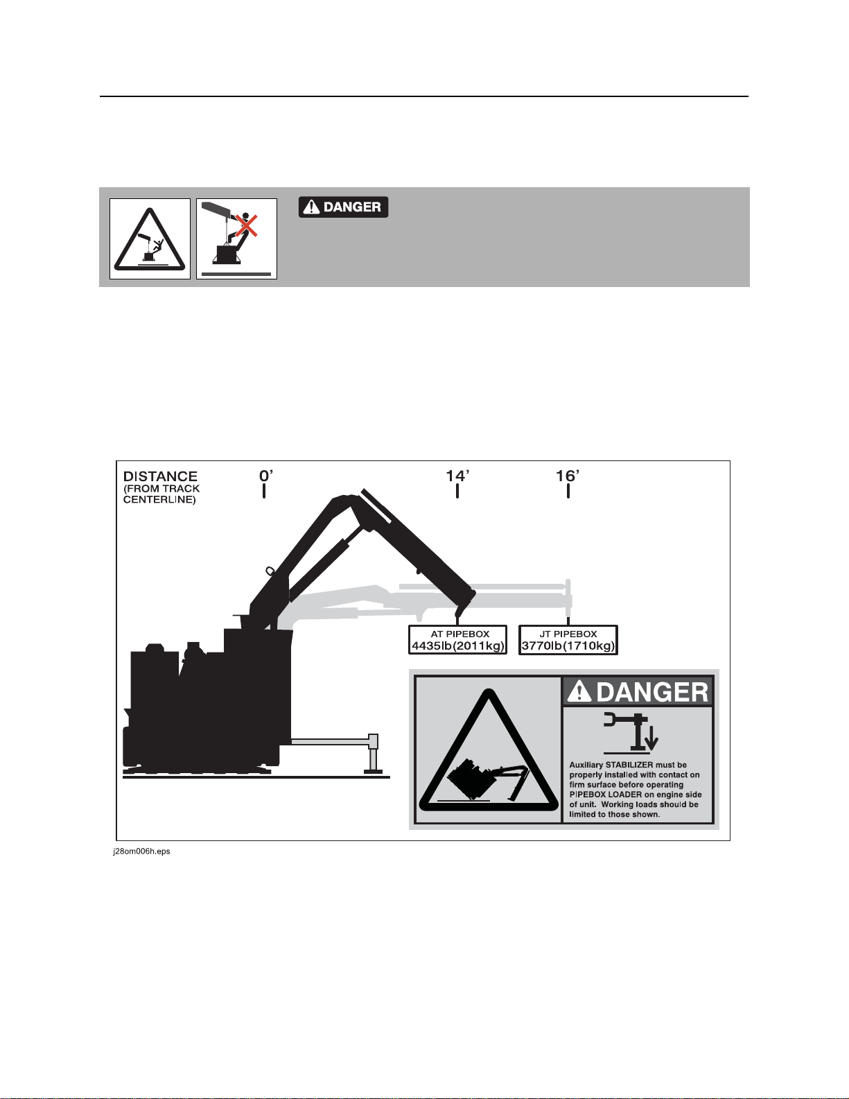
Auxiliary stabilizer must be properly installed with
contact on firm surface before operating pipebox loader on the
engine side of the unit. Working loads should be limited to those
shown.
CMW
©
Page 28

JT100/JT100 All Terrain Operator’s Manual Controls - 27
Controls
Chapter Contents
Set-Up Console . . . . . . . . . . . . . . . . . . . . . . . . . . . 28
Tethered Driver/Loader Controller . . . . . . . . . . . . 31
Overhead Console . . . . . . . . . . . . . . . . . . . . . . . . . 34
Left Control Console . . . . . . . . . . . . . . . . . . . . . . . 36
• Pipeloading Controls . . . . . . . . . . . . . . . . . . . . . . . . . . . . . . . . . . . . . . 36
• Drilling Controls . . . . . . . . . . . . . . . . . . . . . . . . . . . . . . . . . . . . . . . . . . 39
• Operation Controls . . . . . . . . . . . . . . . . . . . . . . . . . . . . . . . . . . . . . . . . 44
Right Control Console . . . . . . . . . . . . . . . . . . . . . . 48
• Engine Display . . . . . . . . . . . . . . . . . . . . . . . . . . . . . . . . . . . . . . . . . . . 48
• Gauges and Indicators . . . . . . . . . . . . . . . . . . . . . . . . . . . . . . . . . . . . . 51
• Lights . . . . . . . . . . . . . . . . . . . . . . . . . . . . . . . . . . . . . . . . . . . . . . . . . . 53
• Controls . . . . . . . . . . . . . . . . . . . . . . . . . . . . . . . . . . . . . . . . . . . . . . . . 56
Fluid Pump . . . . . . . . . . . . . . . . . . . . . . . . . . . . . . . 59
JT/AT System . . . . . . . . . . . . . . . . . . . . . . . . . . . . . 61
Seat . . . . . . . . . . . . . . . . . . . . . . . . . . . . . . . . . . . . . 62
Override Box . . . . . . . . . . . . . . . . . . . . . . . . . . . . . 63
Miscellaneous Controls . . . . . . . . . . . . . . . . . . . . . 65
Battery . . . . . . . . . . . . . . . . . . . . . . . . . . . . . . . . . . . 67
ESID . . . . . . . . . . . . . . . . . . . . . . . . . . . . . . . . . . . . . 68
CMW
©
Page 29
Controls - 28 JT100/JT100 All Terrain Operator’s Manual
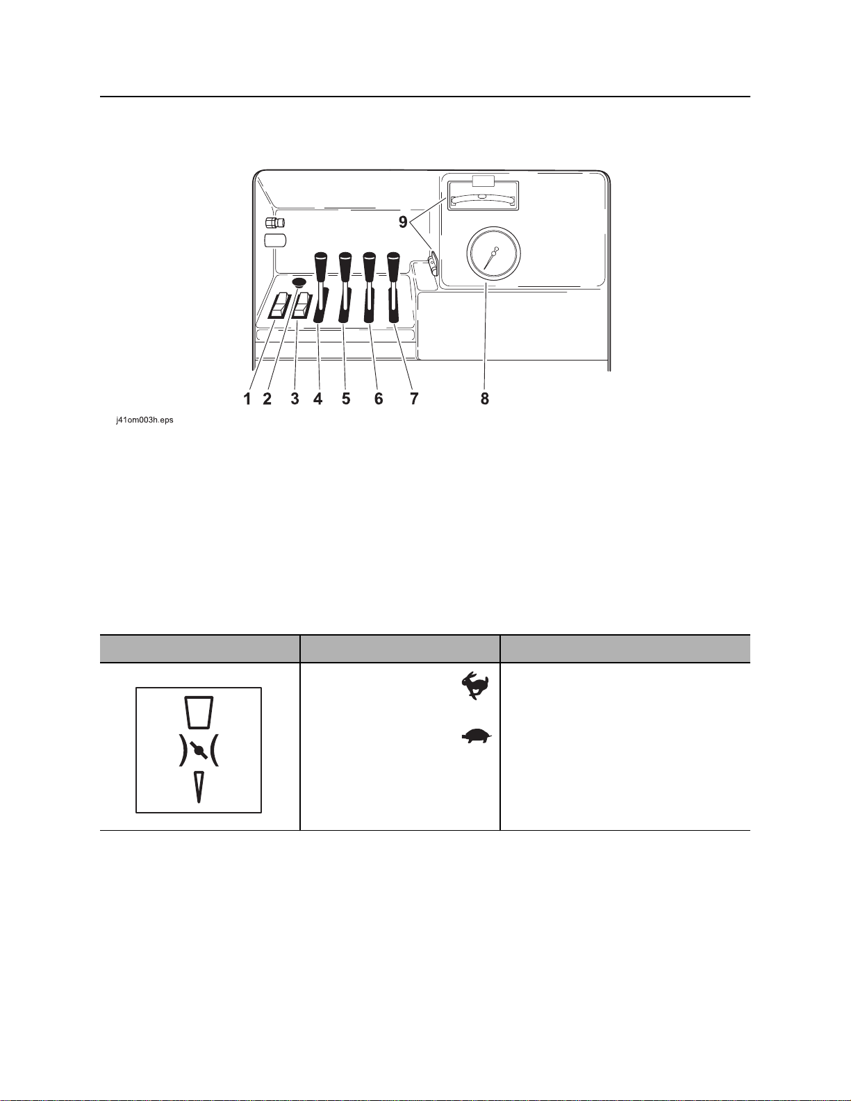
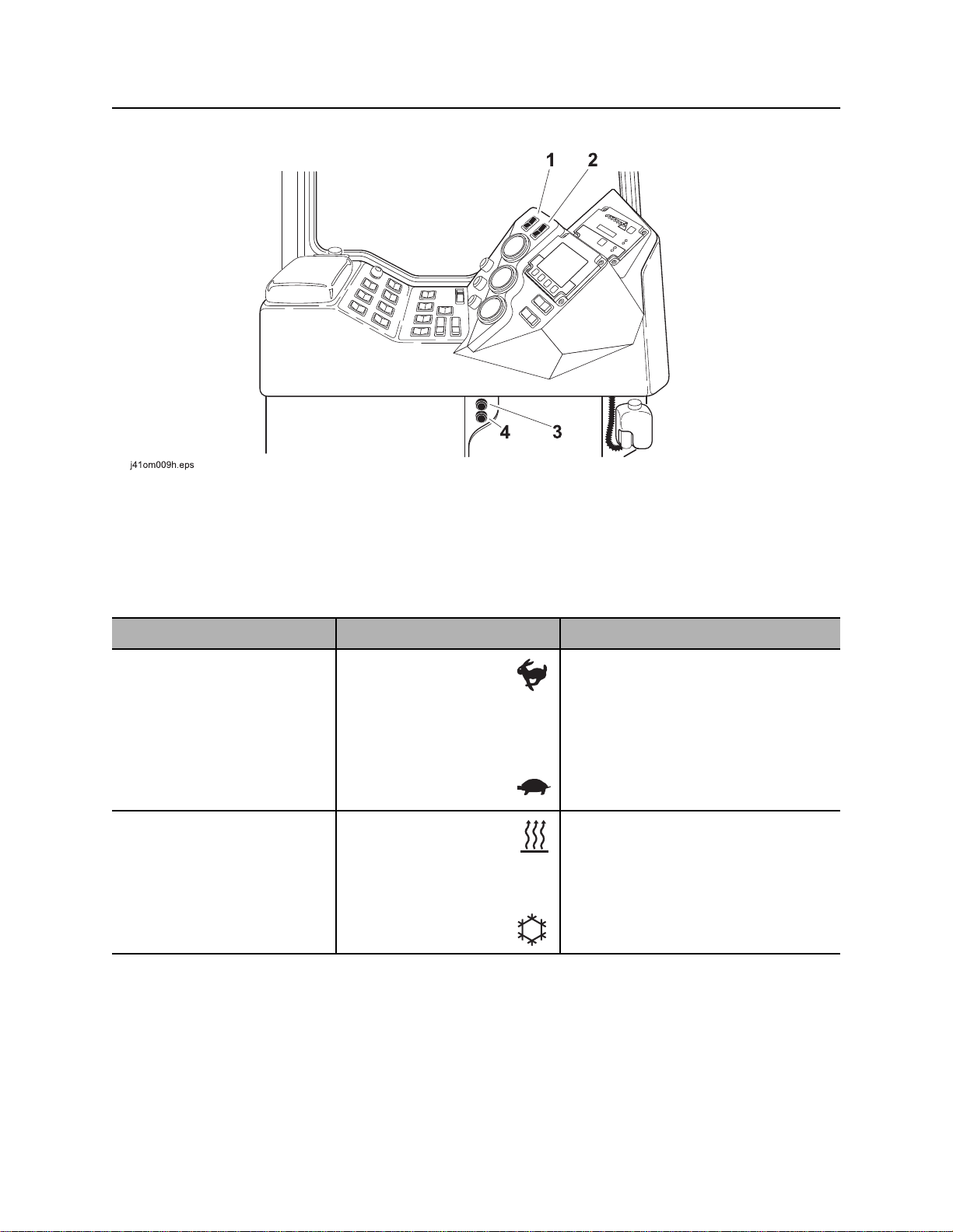
Setup Console
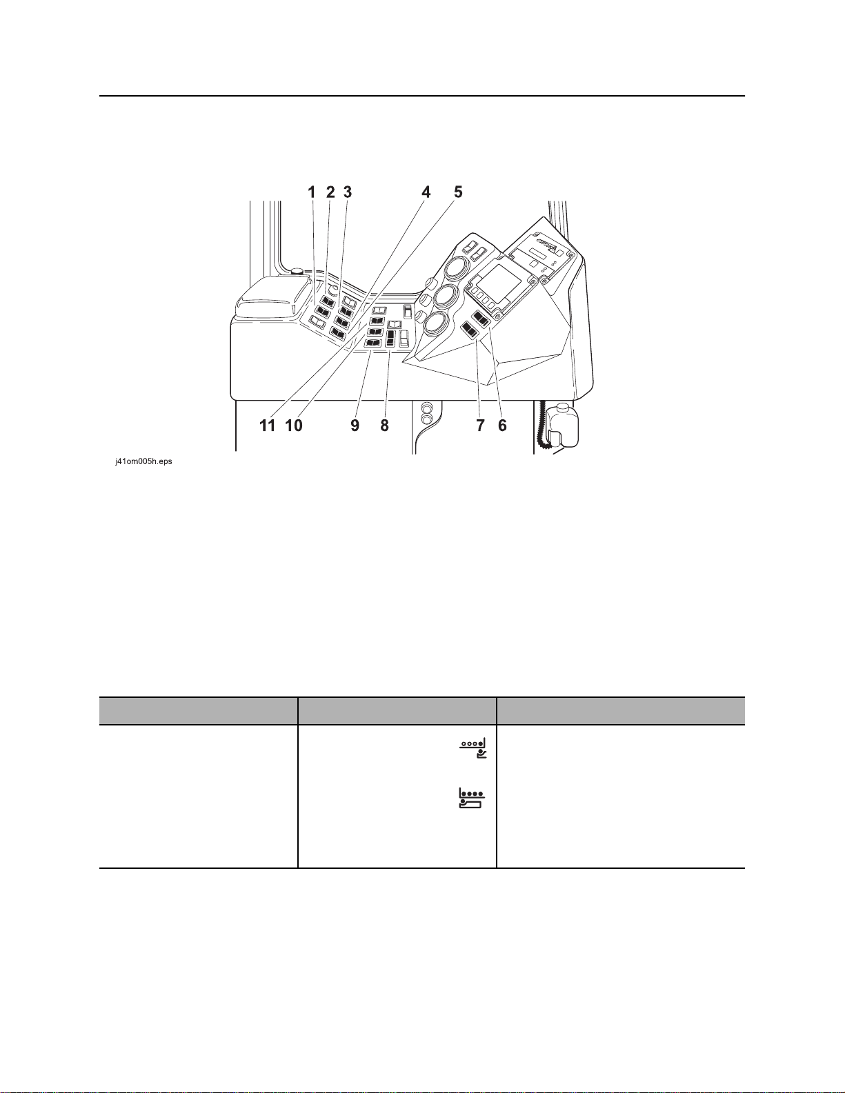
Setup Console
1. Engine throttle switch
2. Remote engine stop switch
3. Auxiliary light switch
4. Left rear stabilizer control
5. Right rear stabilizer control
Item Description Notes
1. Engine throttle switch To increase engine
speed, press
To decrease engine
speed, press
c00ic049t.eps
6. Left front stabilizer control
7. Right front stabilizer control
8. Auxiliary hydraulic pressure gauge
9. Levels
IMPORTANT: Throttle switch at
operator’s station must be in center
position for this switch to control
speed.
CMW
©
Page 30
JT100/JT100 All Terrain Operator’s Manual Controls - 29
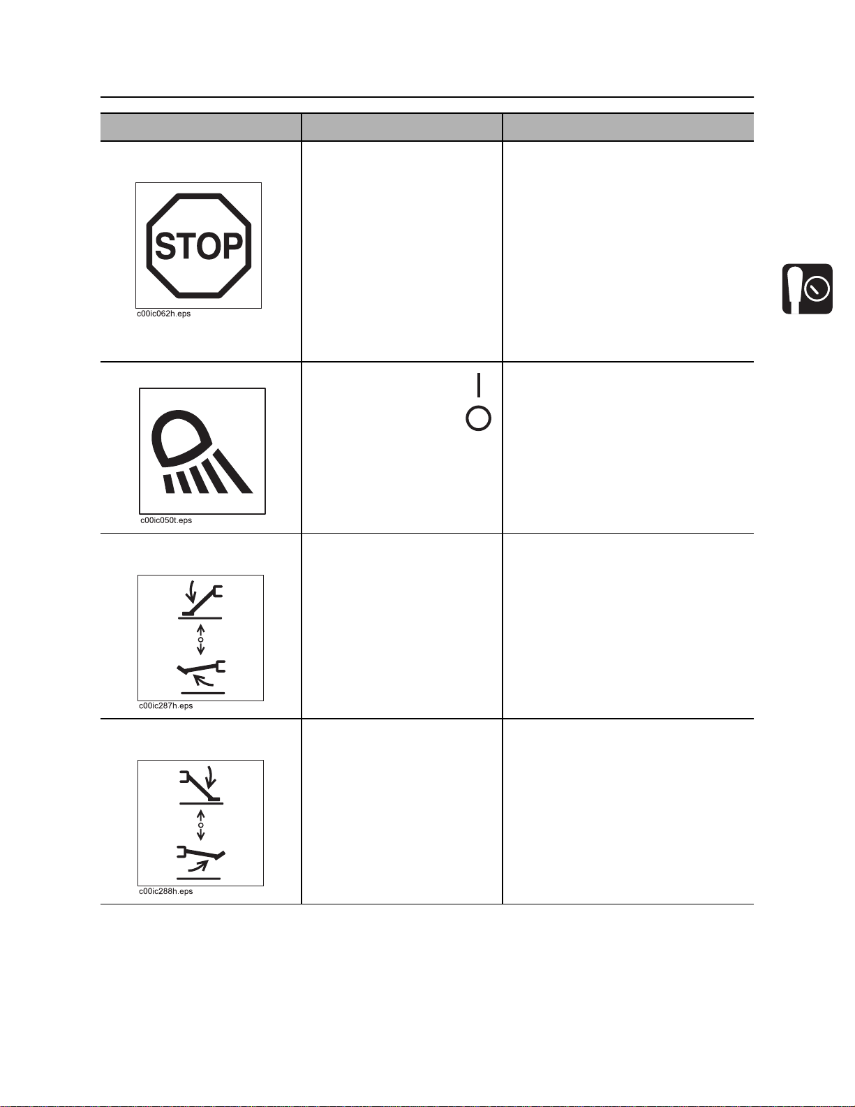
Setup Console
Item Description Notes
2. Remote engine stop
switch
3. Auxiliary light switch To turn on, press
4. Left rear stabilizer
control
To stop engine, press.
To restart engine, turn ignition
off and then back to start.
To turn off, press
To lower, push.
To raise, pull.
IMPORTANT:
• If this switch is used to stop
drilling unit, be sure to turn
ignition switch off if machine will
be left unattended for long
periods of time. Battery discharge
can occur.
• If wrenches are engaged when
remote stop is pressed, wrenches
will remain engaged but could
gradually open.
Lower both rear stabilizers to the
ground together and then adjust
individually.
5. Right rear stabilizer
control
To lower, push.
To raise, pull.
Lower both rear stabilizers to the
ground together and then adjust
individually.
CMW
©
Page 31

Controls - 30 JT100/JT100 All Terrain Operator’s Manual
Setup Console
Item Description Notes
6. Left front stabilizer
control
7. Right front stabilizer
control
8. Auxiliary hydraulic
pressure gauge
To lower, push.
To raise, pull.
To lower, push.
To raise, pull.
Displays hydraulic fluid
pressure to any hydraulic
function in use, including front
and rear stabilizers, optional
pipeloader, stationary and
rotating wrenches, and
optional driver/loader
attachment.
Lower both front stabilizers to the
ground together and then adjust
individually.
Lower both front stabilizers to the
ground together and then adjust
individually.
9. Levels Indicates that drilling unit is
level if bubble rests between
the lines as shown.
Use stabilizer controls to set
machine as level as possible,
both front to back and side to
side.
©
CMW
NOTICE: Failure to stabilize drilling
unit in a level position may hinder
driver/loader swing capabilities.
Page 32

JT100/JT100 All Terrain Operator’s Manual Controls - 31
j
Tethered Driver/Loader Control
Tethered Driver/Loader Control
28om013t.eps
1. Power switch
12
678
6. Driver/Loader arm swing control switch
3
4
5
9
2. Remote engine stop switch
3. Auxiliary control switch
4. Anchor driver control switch
5. Extension control switch
IMPORTANT:
• Tethered driver/loader controller will not work if operator is in drilling unit seat and driver/loader
enable switch is not enabled.
• Before operating driver/loader, release stow strap on driver/loader boom.
7. Outer boom control switch
8. Inner boom control switch
9. Speed control
©
CMW
Page 33

Controls - 32 JT100/JT100 All Terrain Operator’s Manual
Tethered Driver/Loader Control
Item Description Notes
1. Power switch To turn on power to driver/
loader, push to left.
To turn off power to driver/
loader, push to right.
2. Remote engine stop
switch
3. Auxiliary control switch Not used. This switch is reserved for future
4. Anchor driver control
switch
To stop engine, push to right.
auxiliary functions.
To drive anchor (rotate
clockwise), push up and
press speed control.
To remove anchor (rotate
counterclockwise), push
down and press speed
control.
To stop, release switch or
speed control.
5. Inner boom control
switch
©
CMW
To lower, push up and press
speed control.
To raise, push down and
press speed control.
To stop, release switch or
speed control.
Page 34

JT100/JT100 All Terrain Operator’s Manual Controls - 33
Tethered Driver/Loader Control
Item Description Notes
6. Outer boom control
switch
7. Loader/Driver arm
swing control switch
8. Extension control
switch
To lower, push up and press
speed control.
To raise, push down and
press speed control.
To stop, release switch or
speed control.
To swing counterclockwise,
push to left and press speed
control.
To swing clockwise, push to
right and press speed control.
To stop, release switch or
speed control.
To extend, push up and press
speed control.
IMPORTANT: Arm will not swing more
than 360°.
To retract, push down and
press speed control.
To stop, release switch or
speed control.
9. Speed control To start any driver/loader
function, pull gently.
To increase speed, pull closer
to handle.
To stop, release.
CMW
©
Page 35
Controls - 34 JT100/JT100 All Terrain Operator’s Manual
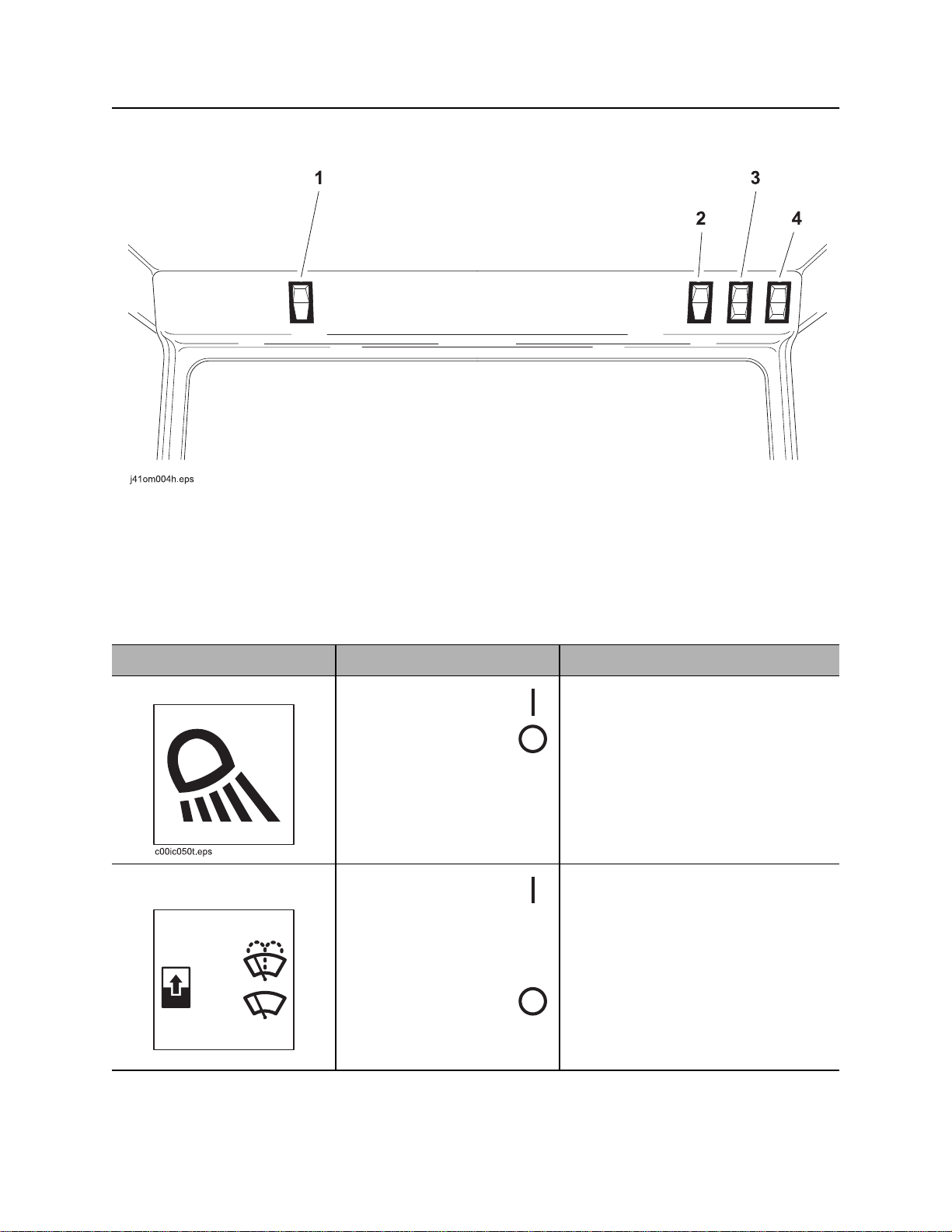
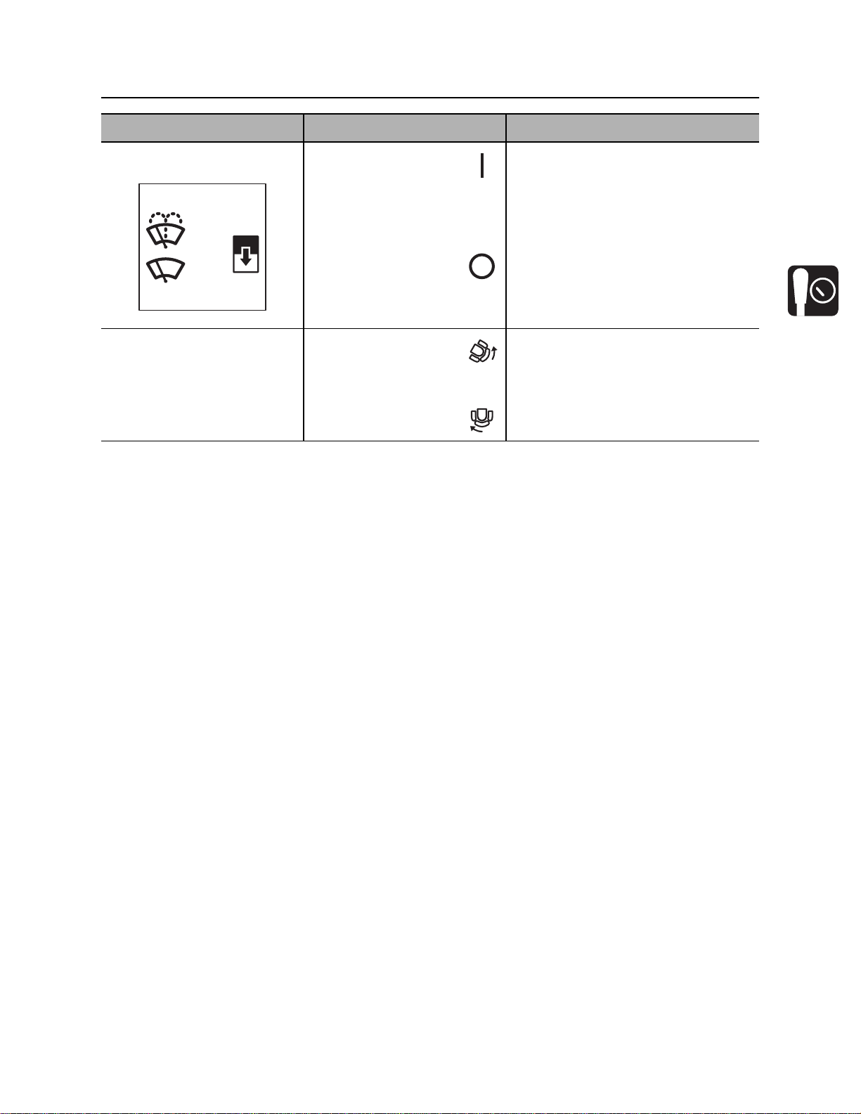
Overhead Console
Overhead Console
1. Light switch
2. Upper windshield wiper switch
Item Description Notes
1. Light switch To turn on, press
To turn off, press
2. Upper windshield wiper
switch
To spray wiper fluid on
windshield, press
To start wiper blade, move to
center.
To stop wiper blade,
press
3. Lower windshield wiper switch
4. Cab pivot control switch
CMW
c00ic051t.eps
©
Page 36
JT100/JT100 All Terrain Operator’s Manual Controls - 35
Overhead Console
Item Description Notes
3. Lower windshield wiper
switch
c00ic052t.eps
4. Cab pivot control
switch
To spray wiper fluid on
windshield, press
To start wiper blade, move to
center.
To stop wiper blade,
press
To move cab into drilling
position, disengage cab
pivot lock and press
To move cab into driving
position, press
See “Cab pivot lock” on page 44 for
more information.
CMW
©
Page 37
Controls - 36 JT100/JT100 All Terrain Operator’s Manual
Left Control Console
Left Control Console
Pipeloading Controls
1. Shuttle stop switch
2. Add pipe/manual/remove pipe switch
3. Pipe lift switch
4. Pipe gripper switch
5. Pipe shuttle switch
6. Front frame tilt switch
Item Description Notes
1. Shuttle stop switch To lower shuttle stop,
press
To raise shuttle stop,
press
7. Back frame tilt switch
8. Pipe lubricator switch
9. Front wrench clamp switch
10. Rear wrench clamp switch
11. Rear wrench rotation switch
IMPORTANT: Look at pipe row
indicator on drill frame to see which
row shuttles will stop under.
IMPORTANT: Shuttles will not
function unless shuttle guard bar on
outside of pipe box is in operating
position.
CMW
©
Page 38

JT100/JT100 All Terrain Operator’s Manual Controls - 37
Left Control Console
Item Description Notes
2. Add pipe/manual/
remove pipe switch
To select “add pipe”
automated pipeloader
function, press green part of
switch.
To use manual pipeloader
controls, move to center.
To select “remove pipe”
c00ic059t.eps
automated pipeloader
function, press white part of
switch.
3. Pipe lift switch To lower, press
To raise, press
4. Pipe gripper switch To close, press
To open, press
5. Pipe shuttle switch To move toward pipe
box, press
To move toward spindle,
press
See “Add Pipe” on page 122.
See “Remove Pipe” on page 130.
IMPORTANT: Shuttles will not
function unless shuttle guard bar on
outside of pipe box is in operating
position.
6. Front frame tilt switch To lower front of drill
frame, press
To raise front of drill
frame, press
7. Back frame tilt switch To lower rear of drill
frame, press
To raise rear of drill
frame, press
8. Pipe lubricator switch To spray joint compound
on threads at saver sub
and wrenches, press
9. Front wrench clamp
To unclamp, press
switch
To clamp, press
CMW
©
Page 39

Controls - 38 JT100/JT100 All Terrain Operator’s Manual
Left Control Console
Item Description Notes
10. Rear wrench clamp
switch
11. Rear wrench rotation
switch
To unclamp, press
To clamp, press
To rotate
counterclockwise, press
To rotate clockwise,
press
To stop rotation, release.
CMW
©
Page 40

JT100/JT100 All Terrain Operator’s Manual Controls - 39
Left Control Console
JT Drilling Controls
1. Spindle brake switch
2. Set/resume switch
3. Rotation speed control
4. Rotation tachometer
Item Description Notes
1. Spindle brake switch To engage, press
IMPORTANT: Use when making
directional change.
To disengage, press
c00ic053t.eps
2. Set/resume switch To resume operation or
See “Cruise Control” on page 172.
increase operation levels,
press green part of switch.
To set operating conditions or
reduce operation levels,
press white part of switch.
c00ic054t.eps
CMW
©
Page 41

Controls - 40 JT100/JT100 All Terrain Operator’s Manual
Left Control Console
Item Description Notes
3. Rotation speed control To increase, turn clockwise.
To decrease, turn
counterclockwise.
4. Rotation tachometer Displays spindle speed.
CMW
©
Page 42
JT100/JT100 All Terrain Operator’s Manual Controls - 41
Left Control Console
AT Drilling Controls
1. Outer spindle brake switch
2. Set/resume switch
3. Outer rotation speed control
4. Outer spindle tachometer
5. Inner spindle tachometer
Item Description Notes
1. Outer spindle brake
switch
c00ic053t.eps
To engage, press
To disengage, press
6. Inner rotation pressure gauge
7. Inner rotation speed control
8. Manual inner rotation switch
9. Inner spindle switch
IMPORTANT: Use when making
directional change.
• Prevents outer spindle from
turning when inner spindle or mud
motor is in use.
• Is temporarily released when front
wrench is closed to allow pipe
change.
CMW
©
Page 43

Controls - 42 JT100/JT100 All Terrain Operator’s Manual
Left Control Console
Item Description Notes
2. Set/resume switch To resume operation or
increase operation levels,
press green part of switch.
To set operating conditions or
reduce operation levels,
press white part of switch.
c00ic054t.eps
3. Outer rotation speed
To increase, turn clockwise.
control
To decrease, turn
counterclockwise.
4. Outer spindle
Displays outer spindle speed.
tachometer
See “Cruise Control” on page 172.
5. Inner spindle
tachometer
©
CMW
Displays inner spindle speed.
Page 44

JT100/JT100 All Terrain Operator’s Manual Controls - 43
Left Control Console
Item Description Notes
6. Inner spindle rotation
pressure gauge
psi x 1000
3
2
1
0
c00ic088t.eps
1
0
4
2
3
5
4
bar
x 100
6
7. Inner rotation speed
control
8. Manual inner rotation
switch
Displays inner spindle
rotation pressure.
To increase, turn clockwise.
To decrease, turn
counterclockwise.
To rotate
counterclockwise, move
switch to left.
IMPORTANT: Inner spindle switch
must be in manual position.
To rotate clockwise,
move switch to right.
9. Inner spindle switch To turn on, press top.
To turn off, move to center.
To manually dither, press
bottom and toggle manual
inner rotation switch left and
right.
c00ic087t.eps
IMPORTANT: To restart inner rotation
after operator has left seat, turn inner
rotation off and then on.
CMW
©
Page 45
Controls - 44 JT100/JT100 All Terrain Operator’s Manual
Left Control Console
Operation Controls
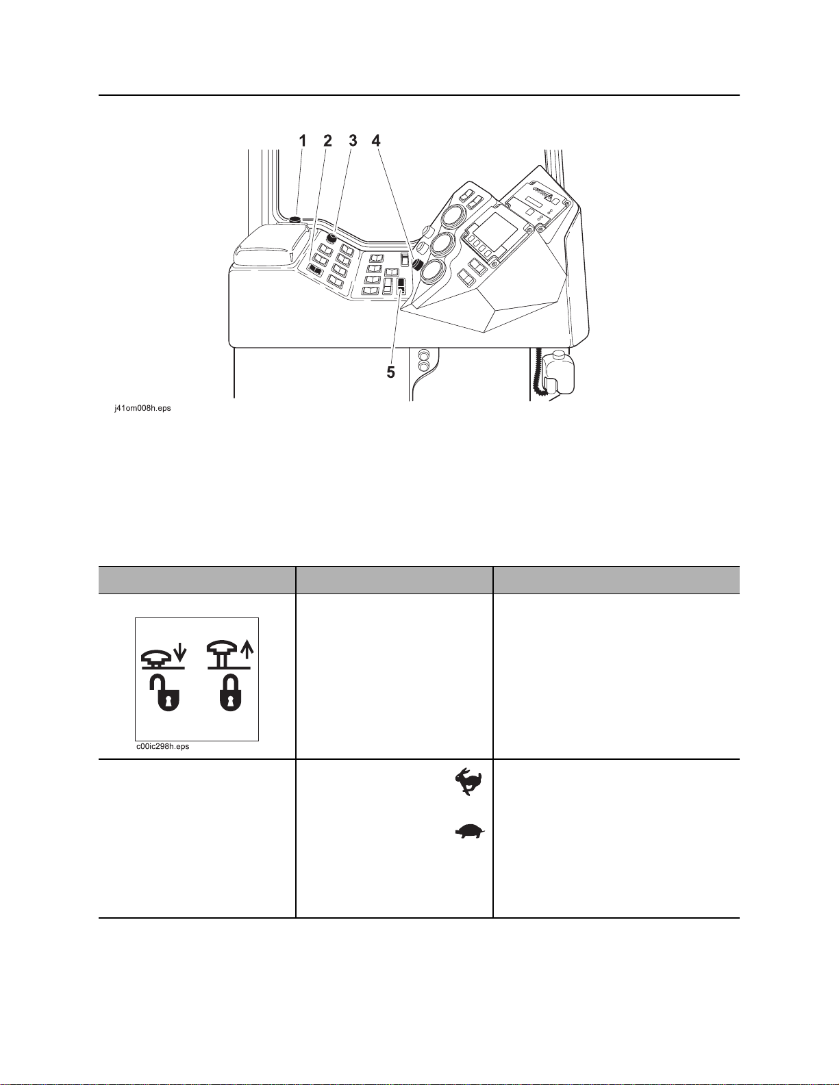
1. Cab pivot lock
2. Engine throttle switch
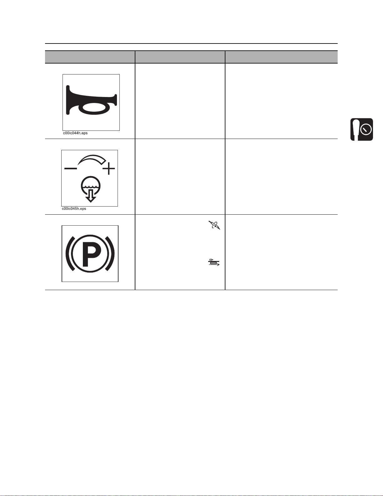
3. Horn
Item Description Notes
1. Cab pivot lock To move cab into drilling
position, press down and
pivot cab into position.
Lock automatically engages
when cab moves into drive
position.
2. Engine throttle switch To increase engine
speed, press
To decrease engine
speed, press
4. Fluid flow control
5. Drill/drive selector
See “Cab pivot control switch” on
page 35 for more information.
CMW
To further increase or
decrease speed, press
additional times.
©
Page 46
JT100/JT100 All Terrain Operator’s Manual Controls - 45
Left Control Console
Item Description Notes
3. Horn To sound horn, press.
4. Fluid flow control To increase flow, turn
clockwise.
To decrease flow, turn
counterclockwise.
5. Drill/drive selector To drill, press
To set parking brake, move to
center.
To drive, press
c00ic055t.eps
CMW
©
Page 47
Controls - 46 JT100/JT100 All Terrain Operator’s Manual
Left Control Console
Climate Controls
1. Climate fan speed selector
2. Climate control control selector
Item Description Notes
1. Climate control fan
speed selector
2. Climate control selector To start heater, press
To select high fan
speed, press
To select medium speed,
move to center.
To select low speed,
press
To turn climate control off,
move to center.
To start air conditioning,
press
3. Heater temperature control
4. Air conditioner temperature control
CMW
©
Page 48

JT100/JT100 All Terrain Operator’s Manual Controls - 47
Left Control Console
Item Description Notes
3. Heater temperature
control
4. Air conditioner
temperature control
To make air warmer, turn
clockwise.
To make air cooler, turn
counterclockwise.
To make air cooler, turn
clockwise.
To make air warmer, turn
counterclockwise.
CMW
©
Page 49
Controls - 48 JT100/JT100 All Terrain Operator’s Manual
Right Control Console
Right Control Console
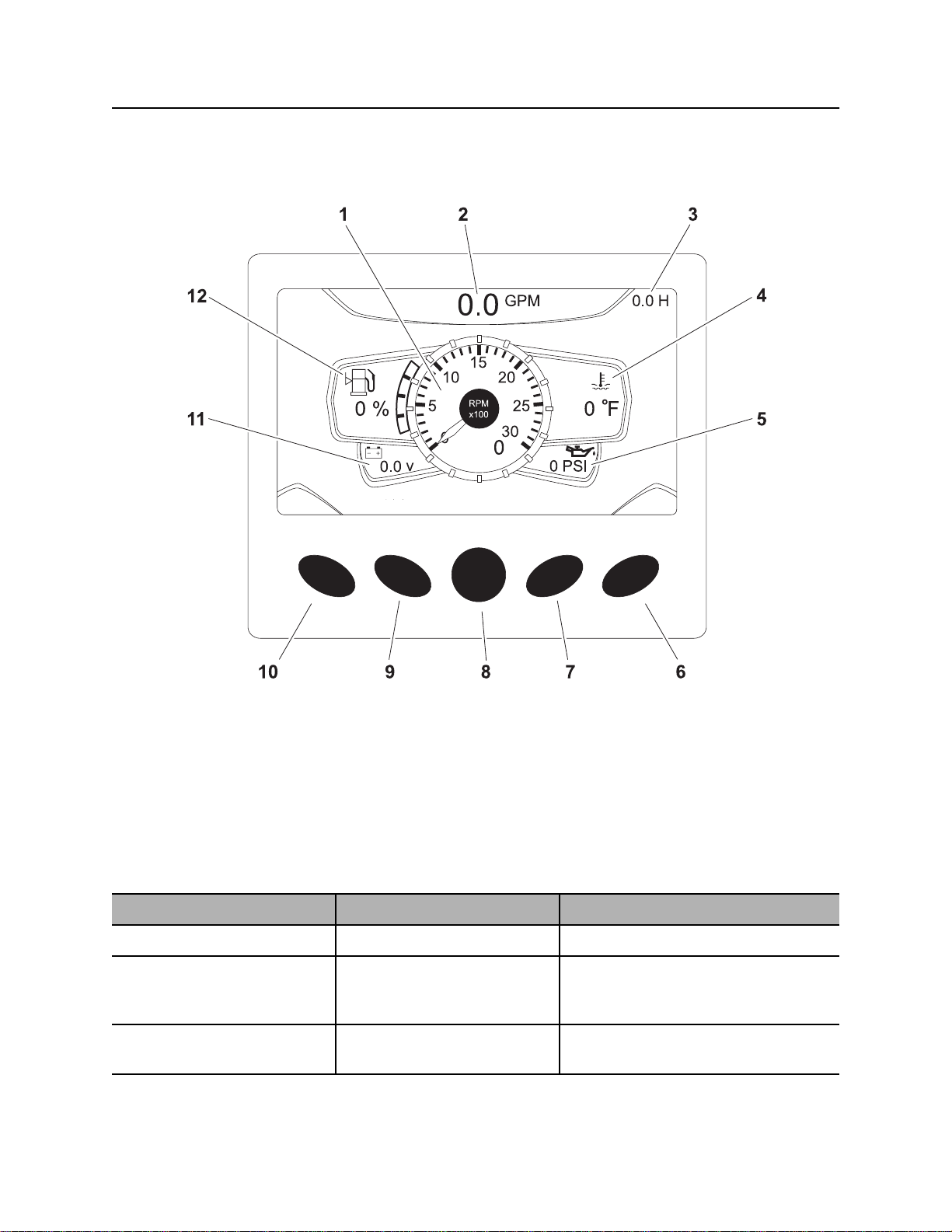
Engine Display
1. Tachometer
2. Drilling fluid flow display
3. Hour meter
4. Engine coolant temperature gauge
5. Engine oil pressure gauge
6. DPF regen mode key
Item Description Notes
1. Tachometer Displays engine speed.
2. Drilling fluid flow
display
3. Hour meter Displays number of hours
©
CMW
Displays the estimated GPM
or LPM of drilling fluid being
pumped.
engine has been running.
7. Soft key
8. Main menu key
9. Soft key
10. Day/Night mode key
11. Voltmeter display
12. Fuel gauge
Page 50

JT100/JT100 All Terrain Operator’s Manual Controls - 49
Right Control Console
Item Description Notes
4. Engine coolant
temperature gauge
5. Engine oil pressure
gauge
6. DPF regen mode key Toggles between automatic
7. Soft key Press to select a soft key
8. Main menu key Press from main screen
9. Soft key Press to select a soft key
10. Day/Night mode key Press from main screen
Displays engine coolant
temperature.
Displays engine oil pressure. Full load reading should be 60-80 psi
(ECU-controlled) and
inhibited DPF regeneration
modes.
command.
(gauges) to select main
menu.
command.
(gauges) to toggle between
day and night modes.
Normal coolant temperature is 180°230° F (82°-110° C).
(4.1-5.5 bar).
Inhibited mode allows the operator to
delay regeneration. The system will
continue to alert the operator that
regeneration is required until the
regeneration is started.
Soft key commands change with each
menu screen and are displayed next
to the key.
Soft key commands change with each
menu screen and are displayed next
to the key.
11. Voltmeter display Shows system voltage. Normal voltage is 13-14V with engine
running.
12. Fuel gauge Displays amount of fuel
remaining in tank.
Most engine display functions are self-explanatory. For more information about functions, see the
manufacturer’s instructions at www.fwmurphy.com.
See “Approved Fuel” on page 189.
Main Menu
IMPORTANT: Soft key commands change with each menu screen and are displayed next to the key.
Item Description Notes
10. System settings key Press to select system
settings menu.
9. User settings key Press to select user settings
menu.
System settings menu displays
information about the system.
Diagnostic information is only
available to dealer technicians.
User settings menu allows user to
change the language and unit
settings, and to set the time and date.
CMW
©
Page 51

Controls - 50 JT100/JT100 All Terrain Operator’s Manual
Right Control Console
Item Description Notes
8. Main screen key Press to return to main
screen (gauges).
7. Engine diagnostics key Press to select engine
diagnostics menu.
6. System operating info Press to show combined
system information screen.
Status Indicators
For dealer technician use only.
For dealer technician use only.
Indicators
DPF Regen inhibited
See engine manual.
DPF Regen indicator
See engine manual.
©
CMW
Hydraulic filter restriction
High hydraulic temperature
Page 52

JT100/JT100 All Terrain Operator’s Manual Controls - 51
Right Control Console
Gauges and Indicators
1. Drilling fluid pressure gauge
2. Thrust pressure gauge
Item Description Notes
1. Drilling fluid pressure
gauge
2. Thrust pressure gauge Displays hydraulic fluid
Displays discharge pressure
of drilling fluid pump.
pressure to thrust motor
during thrust and pullback.
3. Rotation pressure gauge
4. Engine display
IMPORTANT: Monitor this gauge and
drilling fluid flowmeter carefully to see
if values are rising or falling at the
same time. If they are not, nozzle
might be plugged.
CMW
©
Page 53

Controls - 52 JT100/JT100 All Terrain Operator’s Manual
Right Control Console
Item Description Notes
3. Rotation pressure
gauge
4. Engine display Displays engine speed,
Displays hydraulic fluid
pressure to rotation motor
when spindle is turning.
engine data and diagnostic
codes.
See “Engine Display” on page 178
and “Engine Diagnostic Codes” on
page 177 for more information.
CMW
©
Page 54
JT100/JT100 All Terrain Operator’s Manual Controls - 53
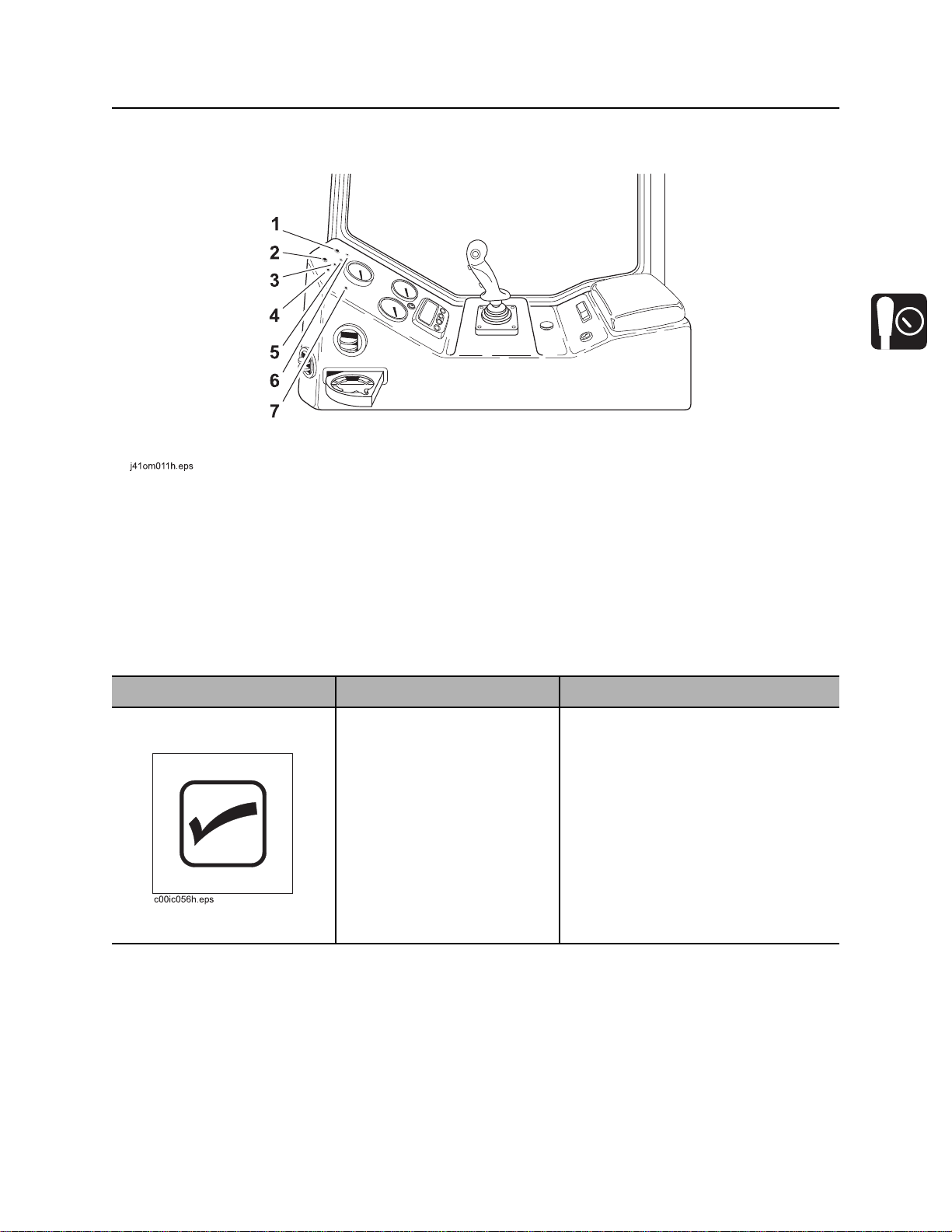
Right Control Console
Lights
1. Control cycle light (green)
2. Diagnostic light (red)
3. Shuttle home status light
4. Rear home status light
Item Description Notes
1. Control cycle light
(green)
If nothing is being controlled,
light is off.
If system is waiting for an
action before starting cycle,
light flashes on and off.
If something is being
controlled, light is on.
If control cycle is interrupted,
light flashes twice quickly.
5. Front home status light
6. Front wrench status light
7. Drilling fluid pump status light
See “Diagnostic Codes” on page 173.
CMW
©
Page 55

Controls - 54 JT100/JT100 All Terrain Operator’s Manual
Right Control Console
Item Description Notes
2. Diagnostic light (red) If system is OK, light is off.
If controller is not getting
power, light is on.
If a non-essential diagnostic
code is recorded, light flashes
on and off for 10 seconds.
If an essential diagnostic
code is recorded, light
continually flashes on for
three seconds and off for half
a second.
See “Diagnostic Codes” on page 173.
3. Shuttle home status
light
4. Rear home status light If carriage is at rear of drill
5. Front home status light If carriage is at front of drill
If shuttle is retracted, light is
on.
If shuttle is extended, light is
off.
frame, light is on.
If carriage is away from rear
of drill frame, light is off.
frame, light is on.
If carriage is away from front
of drill frame, light is off.
IMPORTANT: This light indicates the
shuttle is under the pipe box and out
of the path of the carriage. It does not
mean the shuttle is under the correct
pipe row.
CMW
©
Page 56
JT100/JT100 All Terrain Operator’s Manual Controls - 55
Right Control Console
Item Description Notes
6. Front wrench status
light
7. Drilling fluid pump
status light
If front wrench is closed and
pressured up, light is on.
If front wrench is open or
pressure has dropped, light is
off.
If pump is on, light is on.
If pump is off, light is off.
CMW
©
Page 57

Controls - 56 JT100/JT100 All Terrain Operator’s Manual
Right Control Console
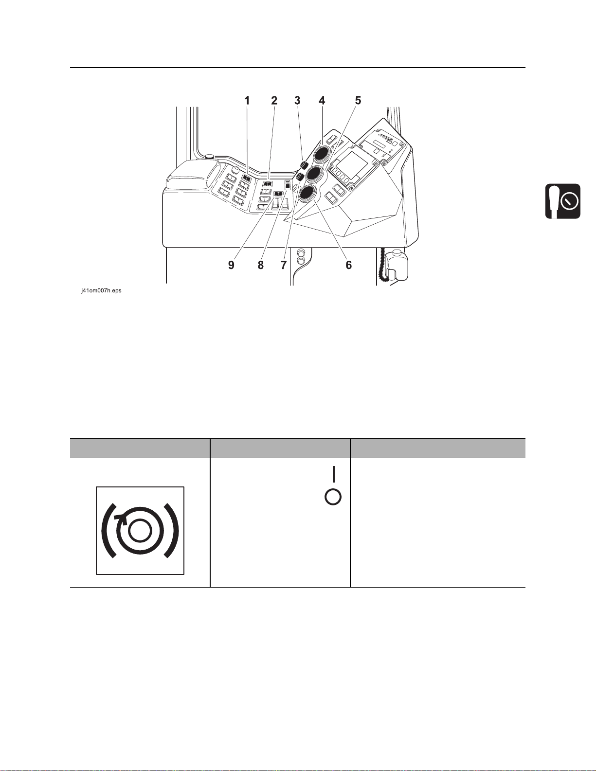
Controls
1. Dual speed carriage control
2. Drilling fluid quick fill switch
3. Drilling fluid pump switch
4. Track and carriage control
Item Description Notes
1. Dual speed carriage
control
To increase carriage travel
speed, push and hold.
To return to normal carriage
speed, release.
5. Shutdown override switch
6. Ignition switch
7. Remote engine stop switch
Use during bore or pullback when no
pipe is in spindle to save time.
IMPORTANT: Drill/drive selector must
be in drill position.
CMW
©
Page 58
JT100/JT100 All Terrain Operator’s Manual Controls - 57
Right Control Console
Item Description Notes
2. Drilling fluid quick fill
switch
3. Drilling fluid pump
switch
4. Track and carriage
control
For full pump flow to fill pipe
with fluid, press and hold.
To return fluid flow to flow
control setting, release.
To turn on, press once.
To turn off, press once.
Track control:
• To move forward, push.
• To move backward, pull.
• To steer, move right or left
while moving.
IMPORTANT: To adjust flow, see
“Fluid flow control” on page 45.
IMPORTANT:
• Drill/drive selector must be in
drive position. See “Steer Unit”
on page 102 for more information.
• Cab must be in drive position.
Carriage control:
• To move carriage
forward, push.
• To move carriage
backward, pull.
• To rotate spindle
counterclockwise
(breakout), move right.
• To rotate spindle
clockwise (makeup),
move left.
IMPORTANT:
• Drill/drive selector must be in drill
position. See “Operate Carriage
Control” on page 115 for more
information.
• Cab can be in either position.
• Shuttle guard bar on outside of
pipe box must be lowered.
CMW
©
Page 59

Controls - 58 JT100/JT100 All Terrain Operator’s Manual
Right Control Console
Item Description Notes
5. Shutdown override
switch
Temporarily override
engine shutdown, press
and hold
c00ic056t.eps
6. Ignition switch To start engine, insert key and
turn clockwise.
To stop engine, turn key
counterclockwise.
7. Remote engine stop
To stop engine, press.
switch
To restart engine, turn ignition
off and then back to start.
IMPORTANT: Restart engine with
ignition switch after it has been turned
off with remote engine stop switch.
IMPORTANT: If this switch is used to
stop drilling unit, be sure to turn
ignition switch off if machine will be
left unattended for long periods of
time. Battery discharge can occur.
CMW
©
Page 60
JT100/JT100 All Terrain Operator’s Manual Controls - 59
j
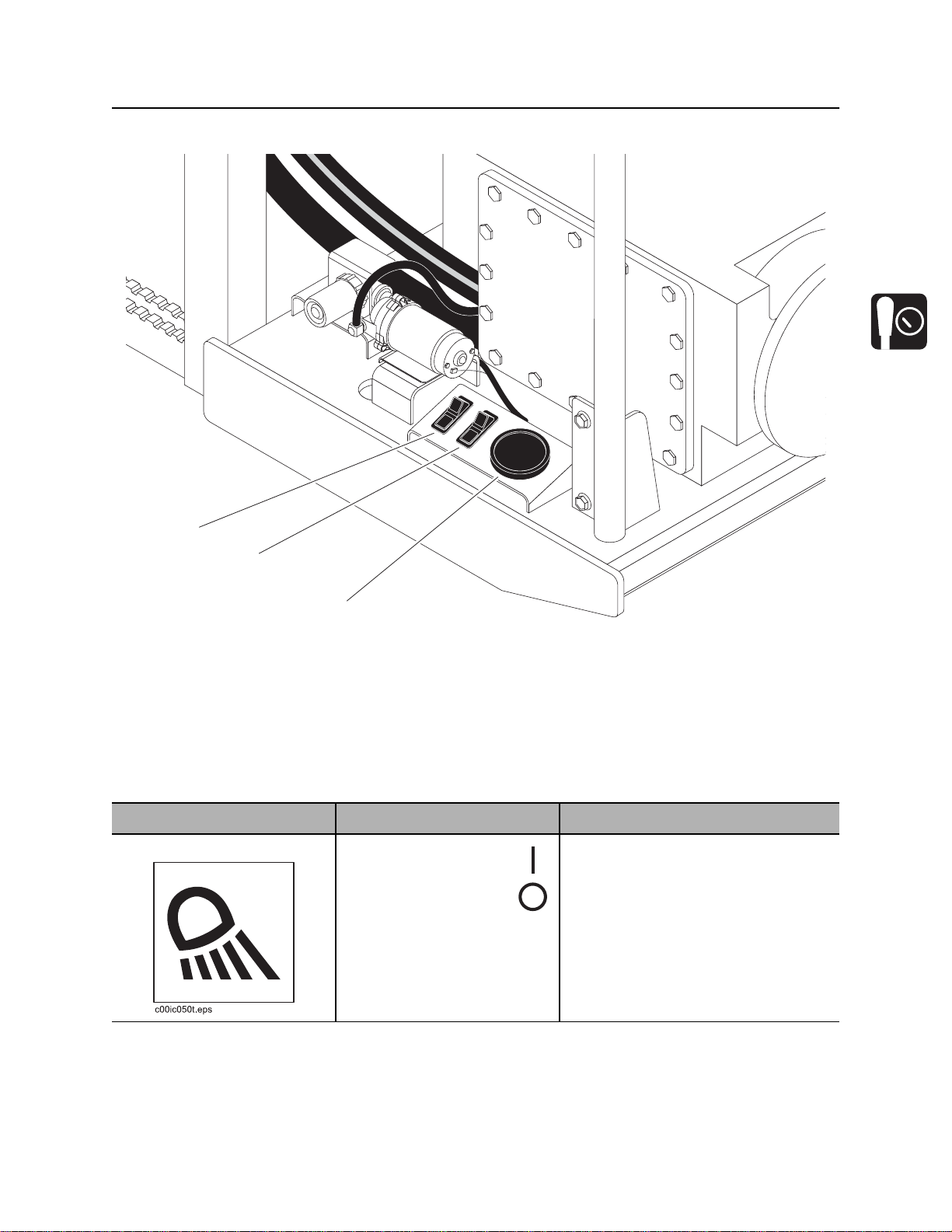
Fluid Pump
Fluid Pump
1
2
3
17om089t.eps
1. Light switch
2. Wash wand switch
Item Description Notes
1. Light switch To turn on, press
To turn off, press
3. Fluid pressure gauge
Controls light at fluid pump work
station.
©
CMW
Page 61
Controls - 60 JT100/JT100 All Terrain Operator’s Manual
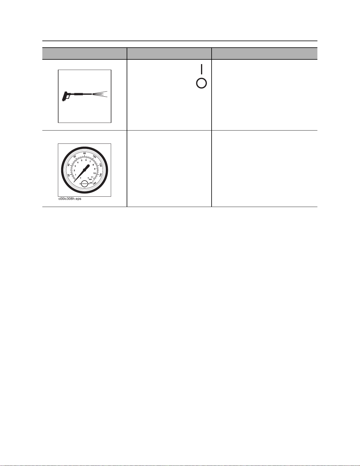
Fluid Pump
Item Description Notes
2. Wash wand switch To spray, press
To turn off, press
c00ic058t.eps
3. Fluid pressure gauge Displays drilling fluid pressure
supplied to the pump.
CMW
©
Page 62
JT100/JT100 All Terrain Operator’s Manual Controls - 61
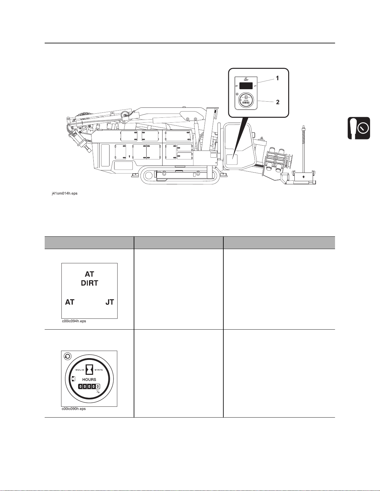
JT/AT System
JT/AT System
1. Mode selector switch 2. Inner rotation hourmeter
Item Description Notes
1. Mode selector switch To select AT mode, press left.
To select AT DIRT mode,
move to center.
To select JT mode, press
right.
2. Inner rotation
hourmeter
Displays inner rotation
operating time.
Use AT or AT DIRT drilling mode
when using AT pipe with inner shaft.
Use JT drilling mode when using JT
pipe without inner shaft.
IMPORTANT: See “Prepare Drilling
Unit” on page 98 for how to set up unit
for each drilling mode.
Use these times to schedule service
for downhole tool and inner shaft. See
“Service” on page 185.
CMW
©
Page 63
Controls - 62 JT100/JT100 All Terrain Operator’s Manual
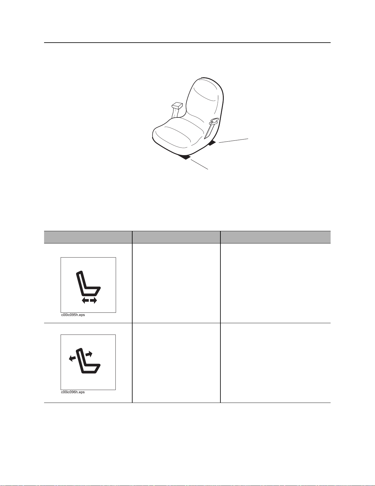
Seat
Seat
2
1
j07om045h.eps
1. Seat slide control 2. Seat recline control
Item Description Notes
1. Seat slide control To slide forward or backward,
move left.
To lock seat in position, move
right.
2. Seat recline control To recline or raise seatback,
lift.
To lock seatback in position,
release.
CMW
©
Page 64

JT100/JT100 All Terrain Operator’s Manual Controls - 63
Emergency Exit
Emergency Exit
Push rear window out and exit to rear of cab.
Override Box
1. Drive override connector
2. Drill override connector
3. Drilling fluid flow override switch
Item Description Notes
1. Drive override
connector
2. Drill override connector Allows drill function override
3. Drilling fluid flow
override switch
Allows drive function override
when box is attached.
when box is attached.
To turn fluid on, move right.
To turn fluid off, move left.
4. Thrust/pullback or right track override switch
5. Rotation or left track override switch
Use switches 4 and 5 to control
tracks.
Use switches 3, 4 and 5 to control drill
functions.
Connect to drill connector (2) to
control fluid flow.
CMW
©
Page 65

Controls - 64 JT100/JT100 All Terrain Operator’s Manual
Override Box
Item Description Notes
4. Thrust/pullback or right
track override switch
5. Rotation or left track
override switch
For thrust or to move track
forward, move up.
For pullback or to move track
backward, move down.
For counterclockwise rotation
or to move track forward,
move up.
For clockwise rotation or to
move track backward, move
down.
Connect to drill connector (2) to
control thrust/pullback.
Connect to drive connector (1) to
control right track.
Connect to drill connector (2) to
control rotation.
Connect to drive connector (1) to
control left track.
CMW
©
Page 66

JT100/JT100 All Terrain Operator’s Manual Controls - 65
Miscellaneous Controls
Miscellaneous Controls
1
23
j28om014t.eps
Item Description Notes
1. Auxiliary outlets Supplies power to work lights
or other 12V devices.
2. Auxiliary outlet Supplies power to 12V
devices.
3. Driver/Loader enable
switch
To enable, press
To disable, press
1
Outlet has power only when ignition
switch is on.
Enables tethered driver/loader
controls to function.
IMPORTANT: Disable driver/loader
when not in use.
CMW
©
Page 67

Controls - 66 JT100/JT100 All Terrain Operator’s Manual
Engine Diagnostic Connector
Engine Diagnostic Connector
Item Description Notes
Engine diagnostic connector Connects diagnostic test
equipment to unit.
CMW
©
Page 68
JT100/JT100 All Terrain Operator’s Manual Controls - 67
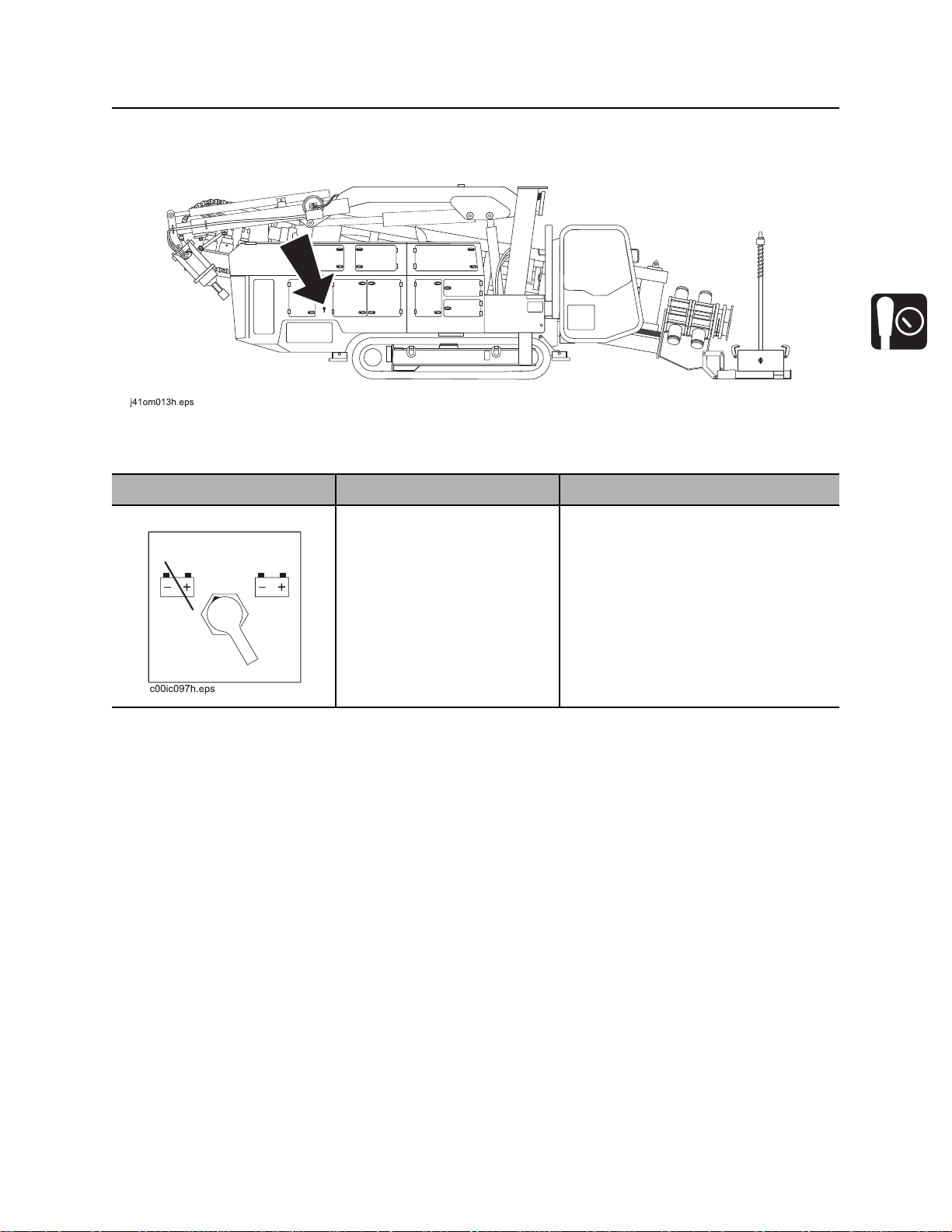
Battery
Battery
Item Description Notes
Battery disconnect switch To connect, move switch so
that indicator points right.
To disconnect, move switch
so that indicator points left.
Use when servicing unit and during
long-term storage.
CMW
©
Page 69
Controls - 68 JT100/JT100 All Terrain Operator’s Manual
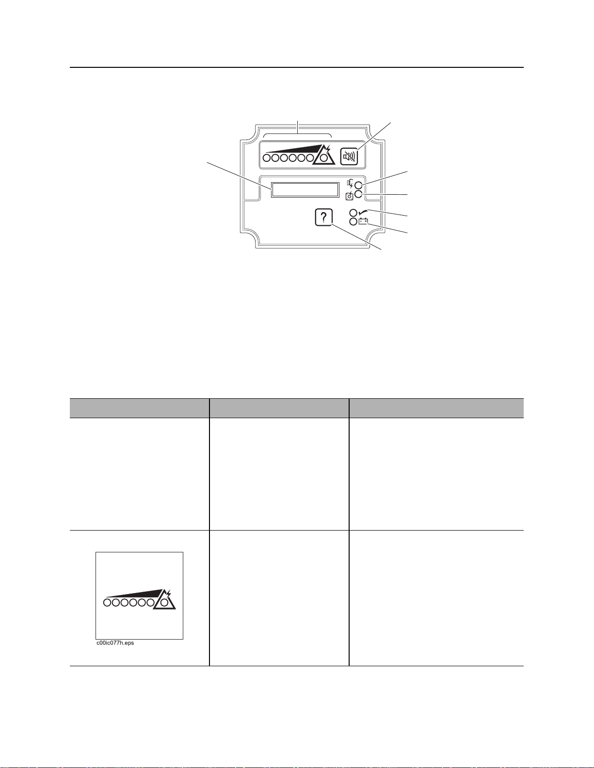
ESID
ESID
23
1
j07om042h.eps
1. Alphanumeric display
2. Strike indicator
3. Alarm interrupt button
4. Voltage problem indicator
Item Description Notes
1. Alphanumeric display Display amount of current
and voltage being detected
as a percentage of strike
condition.
5. Current problem indicator
6. OK indicator
7. Electrical power supply indicator
8. Self test button
4
5
6
7
8
The line with the “V” shows
voltage reading and the line
with the “A” shows current
reading.
2. Strike indicator Red lights come on as values
in display increase.
Light in triangle represents
strike warning condition and
will trigger alarm(s) and
strobe(s).
Remember that system can
go from one or two lights to
an electric strike immediately.
©
CMW
NOTICE: The ESID does not indicate
proximity to electric lines. System will
activate only when voltage and/or
amperage detected at the drilling unit
are above threshold minimum limits.
Page 70

JT100/JT100 All Terrain Operator’s Manual Controls - 69
ESID
Item Description Notes
3. Alarm interrupt button To turn off strike alarm at
drilling unit, press.
4. Voltage problem
indicator
5. Current problem
indicator
6. OK indicator Green light means system
Red light indicates a voltage
indicator problem.
Red light indicates a current
indicator problem.
self test detected no
problems.
See “Troubleshoot Strike System” on
page 148.
See “Troubleshoot Strike System” on
page 148.
Strike system is operating.
CMW
©
Page 71

Controls - 70 JT100/JT100 All Terrain Operator’s Manual
ESID
Item Description Notes
7. Electrical power supply
indicator
8. Self test button To start manual self test,
Green light means control
box has sufficient electrical
power for operation.
Strike system is operating if
OK indicator is also on.
press.
To reset system after a strike
has been detected, press.
Checks all systems and circuits
except voltage limiter.
NOTICE: See “If an Electric Line is
Damaged” on page 18.
CMW
©
Page 72

JT100/JT100 All Terrain Operator’s Manual Operation Overview - 71
Operation Overview
Chapter Contents
Planning. . . . . . . . . . . . . . . . . . . . . . . . . . . . . . . . . . 72
Setting Up at Jobsite . . . . . . . . . . . . . . . . . . . . . . . 72
Drilling . . . . . . . . . . . . . . . . . . . . . . . . . . . . . . . . . . . 73
Backreaming . . . . . . . . . . . . . . . . . . . . . . . . . . . . . . 74
Leaving Jobsite. . . . . . . . . . . . . . . . . . . . . . . . . . . . 74
Storing Equipment . . . . . . . . . . . . . . . . . . . . . . . . . 74
CMW
©
Page 73

Operation Overview - 72 JT100/JT100 All Terrain Operator’s Manual
Planning
Planning
1. Gather information about jobsite. See page 77.
2. Inspect jobsite. See page 78.
3. Classify jobsite. See page 80.
4. Plan bore path. See page 83.
5. Check supplies and prepare equipment. See page 95.
6. Load equipment. See page 107.
Setting Up at Jobsite
1. Prepare jobsite. See page 94.
2. Unload drilling unit from trailer. See page 109.
3. Assemble drill string. See page 117.
4. Position drilling unit and frame. See page 113.
5. Assemble strike system. See page 146.
6. Anchor drilling unit. See page 135.
7. Connect fluid system. See page 113.
8. Calibrate tracker with beacon that will be installed in beacon housing. See tracker operator’s manual.
CMW
©
Page 74

JT100/JT100 All Terrain Operator’s Manual Operation Overview - 73
Drilling
Drilling
1. Start system. See page 114.
2. Engage tracker control if desired. See page 157.
3. Drill first pipe. See page 120.
• JT mode
• AT dirt mode
• AT mode
4. Swab the hole to remove cuttings (AT mode only). See page 121.
5. Record bore path. See page 126.
6. Enable automated pipeloader system. See page 121.
7. Add pipe. See page 122.
8. Drill remaining pipes in pipe box.
• Correct direction. See page 124.
• Engage cruise control. See page 172.
9. Remove empty pipe box and add full box (see page 139) to complete bore.
10. Surface drill head. See page 127.
• Remove drill head.
• Grease downhole tool (AT mode). See page 191.
CMW
©
Page 75

Operation Overview - 74 JT100/JT100 All Terrain Operator’s Manual
Backreaming
Backreaming
1. Assemble backream string. See page 128.
2. Start drilling unit and adjust throttle.
3. Set drilling fluid flow. Check that fluid flows through all nozzles. See page 160.
4. Remove pipe from bore. See page 130.
5. Remove full pipe box and add empty box (see page 139) to complete backream.
6. Remove pullback device. See page 132.
Backreaming Tips
• Plan backreaming job before drilling. Plan bore path as straight as possible. Check bend limits of
pullback material. Check that appropriate pullback devices are on hand.
• Keep all bends as gradual as possible.
• Drilling fluid quality is a key factor in backreaming success. Contact your Ditch Witch® dealer for
information on testing water, selecting additives, and mixing drilling fluid.
• Backreaming requires more fluid than drilling. Make sure enough fluid is used.
Leaving Jobsite
1. Remove anchors. See page 135.
2. Rinse unit and downhole tools. See page 181.
3. Disassemble strike system (see page 146) and disconnect from fluid system (see page 183).
4. Stow tools. See page 183.
5. Load unit onto trailer. See page 107.
Storing Equipment
1. For cold weather storage, antifreeze drilling unit. See page 180.
2. For long-term storage, disconnect battery disconnect switch.
CMW
©
Page 76

JT100/JT100 All Terrain Operator’s Manual Prepare - 75
Prepare
Chapter Contents
Gather Information . . . . . . . . . . . . . . . . . . . . . . . . . 77
• Review Job Plan . . . . . . . . . . . . . . . . . . . . . . . . . . . . . . . . . . . . . . . . . . 77
• Notify One-Call Services. . . . . . . . . . . . . . . . . . . . . . . . . . . . . . . . . . . . 77
• Examine Pullback Material . . . . . . . . . . . . . . . . . . . . . . . . . . . . . . . . . . 77
• Arrange for Traffic Control. . . . . . . . . . . . . . . . . . . . . . . . . . . . . . . . . . . 77
• Plan for Emergency Services . . . . . . . . . . . . . . . . . . . . . . . . . . . . . . . . 77
Inspect Site . . . . . . . . . . . . . . . . . . . . . . . . . . . . . . . 78
• Identify Hazards . . . . . . . . . . . . . . . . . . . . . . . . . . . . . . . . . . . . . . . . . . 78
• Select Start and End Points . . . . . . . . . . . . . . . . . . . . . . . . . . . . . . . . . 79
Classify Jobsite. . . . . . . . . . . . . . . . . . . . . . . . . . . . 80
• Inspect Jobsite . . . . . . . . . . . . . . . . . . . . . . . . . . . . . . . . . . . . . . . . . . . 80
• Select a Classification. . . . . . . . . . . . . . . . . . . . . . . . . . . . . . . . . . . . . . 80
• Apply Precautions. . . . . . . . . . . . . . . . . . . . . . . . . . . . . . . . . . . . . . . . . 81
Plan Bore Path . . . . . . . . . . . . . . . . . . . . . . . . . . . . 83
• Recommended Bend Limits . . . . . . . . . . . . . . . . . . . . . . . . . . . . . . . . . 84
• Entry Pitch. . . . . . . . . . . . . . . . . . . . . . . . . . . . . . . . . . . . . . . . . . . . . . . 89
• Minimum Setback . . . . . . . . . . . . . . . . . . . . . . . . . . . . . . . . . . . . . . . . . 90
• Minimum Depth. . . . . . . . . . . . . . . . . . . . . . . . . . . . . . . . . . . . . . . . . . . 90
• Bore Path Calculator. . . . . . . . . . . . . . . . . . . . . . . . . . . . . . . . . . . . . . . 91
CMW
©
Page 77

Prepare - 76 JT100/JT100 All Terrain Operator’s Manual
Prepare Jobsite. . . . . . . . . . . . . . . . . . . . . . . . . . . . 94
• Mark Bore Path. . . . . . . . . . . . . . . . . . . . . . . . . . . . . . . . . . . . . . . . . . . 94
• Prepare Entry Point. . . . . . . . . . . . . . . . . . . . . . . . . . . . . . . . . . . . . . . . 94
Check Supplies and Prepare Equipment . . . . . . . 95
• Check Supplies. . . . . . . . . . . . . . . . . . . . . . . . . . . . . . . . . . . . . . . . . . . 95
• Prepare Equipment. . . . . . . . . . . . . . . . . . . . . . . . . . . . . . . . . . . . . . . . 96
• Select Drilling Mode . . . . . . . . . . . . . . . . . . . . . . . . . . . . . . . . . . . . . . . 97
• Prepare Drilling Unit . . . . . . . . . . . . . . . . . . . . . . . . . . . . . . . . . . . . . . . 98
• Assemble Accessories . . . . . . . . . . . . . . . . . . . . . . . . . . . . . . . . . . . . . 99
CMW
©
Page 78

JT100/JT100 All Terrain Operator’s Manual Prepare - 77
Gather Information
Gather Information
A successful job begins before the bore. The first step in planning is reviewing information already
available about the job and jobsite.
Review Job Plan
Review blueprints or other plans and make sure you have taken bore enlargement during backreaming
and pullback into account. Check for information about existing or planned structures, elevations, or
proposed work that may be taking place at the same time.
Notify One-Call Services
Contact your local One-Call (811 in USA) or the One-Call referral number (888-258-0808 in USA and
Canada) to have underground utilities located before digging. Also contact any utilities that do not
participate in the One-Call service.
Examine Pullback Material
Ask for a sample of the material you will be pulling back. Check its weight and stiffness. Contact the
manufacturer for bend radius information. Check that you have appropriate pullback devices.
Arrange for Traffic Control
If working near a road or other traffic area, contact local authorities about safety procedures and
regulations.
Plan for Emergency Services
Have the telephone numbers for local emergency and medical facilities on hand. Check that you will have
access to a telephone.
CMW
©
Page 79

Prepare - 78 JT100/JT100 All Terrain Operator’s Manual
Inspect Site
Inspect Site
Inspect jobsite before transporting equipment. Check for the following:
• overall grade or slope
• changes in elevation such as hills or open trenches
• obstacles such as buildings, railroad crossings, or streams
• signs of utilities (See “Inspect Jobsite” on page 80.)
• traffic
• access
• soil type and condition
• water supply
• sources of locator interference (rebar, railroad tracks, etc.)
Take soil samples from several locations along bore path to determine best bit and backreamer
combinations.
Identify Hazards
Identify safety hazards and classify jobsite. See “Classify Jobsite” on page 80.
Jobsite hazards could cause death or serious injury. Use
correct equipment and work methods. Use and maintain proper safety
equipment.
To help avoid injury:
• Wear personal protective equipment including hard hat, safety eye wear, and hearing protection.
• Do not wear jewelry or loose clothing.
• Notify One-Call and companies which do not subscribe to One-Call.
• Comply with all utility notification regulations before digging or drilling.
• Verify location of previously marked underground hazards.
• Mark jobsite clearly and keep spectators away.
Remember, jobsite is classified by hazards in place -- not by line being installed.
CMW
©
Page 80

JT100/JT100 All Terrain Operator’s Manual Prepare - 79
Inspect Site
Select Start and End Points
Select one end to use as a starting point. Consider the following when selecting a starting point:
Slope
Fluid system should be parked on a level site. Consider how slope will affect drilling unit setup, bending
pipe, and fluid flow out of hole.
Traffic
Vehicle and pedestrian traffic must be a safe distance from drilling equipment. Allow at least 10’ (3 m)
buffer zone around equipment.
Space
Check that starting and ending points allow enough space for gradual pipe bending. See “Minimum
Setback” on page 90.
Check that there is enough space to work and to set up electric strike system.
Comfort
Consider shade, wind, fumes, and other site features.
Drill downhill when possible so fluid will flow away from drilling unit.
CMW
©
Page 81

Prepare - 80 JT100/JT100 All Terrain Operator’s Manual
Classify Jobsite
Classify Jobsite
Inspect Jobsite
• Follow U.S. Department of Labor regulations on excavating and trenching (Part 1926, Subpart P) and
other similar regulations.
• Contact your local One-Call (811 in USA) or the One-Call referral number (888-258-0808 in USA and
Canada) to have underground utilities located before digging. Also contact any utilities that do not
participate in the One-Call service.
• Inspect jobsite and perimeter for evidence of underground hazards, such as:
– “buried utility” notices
– utility facilities without overhead lines
– gas or water meters
– junction boxes
– drop boxes
– light poles
– manhole covers
– sunken ground
• Have an experienced locating equipment operator sweep area within 20’ (6 m) to each side of bore
path. Verify previously marked line and cable locations.
• Mark location of all buried utilities and obstructions.
• Classify jobsite.
Select a Classification
Jobsites are classified according to underground hazards present.
If working. . . then classify jobsite as . . .
within 10’ (3 m) of a buried electric line electric
within 10’ (3 m) of a natural gas line natural gas
in sand or granite which is capable of producing crystalline silica
(quartz) dust
within 10’ (3 m) of any other hazard other
NOTICE: If you have any doubt about jobsite classification, or if jobsite might contain unmarked
hazards, take steps outlined previously to identify hazards and classify jobsite before working.
crystalline silica (quartz) dust
CMW
©
Page 82

JT100/JT100 All Terrain Operator’s Manual Prepare - 81
Classify Jobsite
Apply Precautions
Once classified, precautions appropriate for jobsite must be taken.
Electric Jobsite Precautions
Electric shock will cause death or serious injury. Stay
away.
In addition to using a directional drilling system with an electric strike system, use one or both of these
methods.
• Expose line by careful hand digging or soft excavation. Use beacon to track bore path. Have someone
observe clearance between drill head and backreamer when crossing a line.
• Have service shut down while work is in progress. Have electric company test lines before returning
them to service.
Natural Gas Jobsite Precautions
Fire or explosion possible. Fumes could ignite and cause
burns. No smoking, no flame, no spark.
In addition to using a directional drilling system and positioning equipment upwind from gas lines, use one
or both of these methods.
• Expose lines by careful hand digging or soft excavation. Use beacon to track bore path. Have
someone observe clearance between drill head and backreamer when crossing a line.
• Have gas shut off while work is in progress. Have gas company test lines before returning them to
service.
CMW
©
Page 83

Prepare - 82 JT100/JT100 All Terrain Operator’s Manual
Classify Jobsite
Crystalline Silica (Quartz) Dust Precautions
Use breathing protection when exposed to silica dust.
Follow OSHA or other guidelines for exposure to crystalline silica when trenching, sawing or drilling
through material that might produce dust containing crystalline silica (quartz).
Other Jobsite Precautions
You may need to use different methods to safely avoid other underground hazards. Talk with those
knowledgeable about hazards present at each site to determine which precautions should be taken or if
job should be attempted.
CMW
©
Page 84

JT100/JT100 All Terrain Operator’s Manual Prepare - 83
Plan Bore Path
Plan Bore Path
Plan the bore path, from entry to end, before drilling begins. The Ditch Witch® Trac Management System
Plus is available for planning your bore path. This special software can be run in the field using a laptop
computer equipped with Windows® 95 or higher operating system. See your Ditch Witch dealer for details.
If not using Trac Management System Plus, mark the bore path on the ground with spray paint or flags, or
record it on paper for operator reference.
For complicated bores, consult an engineer. Have the jobsite surveyed and bore path calculated. Be sure
the engineer knows minimum entry pitch, bend limits of drill pipe, bend and tension limits of pullback
material, pipe lengths, and location of all underground utilities.
For less complicated bores, plan the bore based on four measurements:
• recommended bend limit
• entry pitch
• minimum setback
• minimum depth
IMPORTANT: See the following pages for more information about these measurements. If not using
Trac Management System Plus, see “Bore Path Calculator - Power Pipe®” on page 91 and use these
measurements to help plan your bore.
CMW
©
Page 85

Prepare - 84 JT100/JT100 All Terrain Operator’s Manual
Plan Bore Path
Recommended Bend Limits
Ditch Witch drill pipes are designed to bend slightly during operation. Slight bending allows for steering and
correcting direction. Bending beyond recommended limits will cause damage that might not be visible. This
damage adds up and will later lead to sudden drill pipe failure.
IMPORTANT: Consider recommended bend limits during any bend, not just during bore entry.
Pipe Pitch
Ditch Witch® drill pipe is tested to bend at a maximum
percent pitch.
• For JT100 Power Pipe® drill pipe, make sure pitch
(A) changes no more than 7% over the full length
of each pipe.
• For JT100 Power Pipe Forged drill pipe, make
sure pitch (A) changes no more than 7.6% over
the full length of each pipe.
• For JT100 All Terrain drill pipe, make sure pitch
(A) changes no more than 7% over the full length
of each pipe.
NOTICE: Bending drill pipe more sharply than recommended will damage pipe and cause failure
over time. Changes in pitch must be equally distributed over the length of a pipe. Maximum
changes in pitch within 1-2’ (300-600 mm) of pipe create sharp bends that will damage pipe.
Monitor the pitch of each pipe with the remote display on the operator’s console. See tracker manual.
CMW
©
Page 86

JT100/JT100 All Terrain Operator’s Manual Prepare - 85
Plan Bore Path
Bend Radius
JT100 Power Pipe® drill pipes have a tested minimum
bend radius of 205’ (62.5 m). This means that a 90°
bend in the bore path:
• has a radius (A) of 205’ (62.5 m)
• requires approximately 325’ (99 m) of drill pipe
(B).
JT100 Power Pipe Forged drill pipes have a tested
minimum bend radius of 197’ (60 m). This means that
a 90° bend in the bore path:
• has a radius (A) of 197’ (60 m)
• requires approximately 310’ (94.5 m) of drill
pipe (B).
JT100 All Terrain drill pipes have a tested minimum bend radius of 205’ (62.5). This means that a 90° bend
in the bore path:
• has a radius (A) of 205’ (62.5 m)
• requires approximately 325’ (99 m) of drill pipe (B).
NOTICE: Bending drill pipe more sharply than recommended will damage the pipe and cause failure
over time.
• If bend radius is reduced, drill pipe life is reduced.
• If bend radius is increased, drill pipe life is increased.
IMPORTANT: Use the charts on the next page to keep bends within safe limits.
CMW
©
Page 87

Prepare - 86 JT100/JT100 All Terrain Operator’s Manual
Plan Bore Path
Pipe-By-Pipe Bend Limits - Power Pipe
Pipe
(C)
1 14 ft 9 in (4.5 m) 0 ft 6 in (0.2 m) 12 155 ft 11 in (47.5 m) 71 ft 11 in (21.9 m)
2 29 ft 5 in (9.0 m) 2 ft 1 in (0.6 m) 13 165 ft 1 in (50.3 m) 83 ft 6 in (25.4 m)
3 43 ft 11 in (13.4 m) 4 ft 9 in (1.5 m) 14 173 ft 5 in (52.9 m) 95 ft 8 in (29.2 m)
4 58 ft 3 in (17.8 m) 8 ft 5 in (2.6 m) 15 180 ft 10 in (55.1 m) 108 ft 5 in (33.1 m)
5 72 ft 3 in (22 m) 13 ft 2 in (4.0 m) 16 187 ft 4 in (57.1 m) 121 ft 8 in (37.1 m)
6 85 ft 10 in (26.2 m) 18 ft 10 in (5.7 m) 17 192 ft 10 in (58.8 in) 135 ft 5 in (41.3 m)
7 99 ft 0 in (30.2 m) 25 ft 6 in (7.8 m) 18 197 ft 4 in (60.1 m) 149 ft 5 in (45.6 m)
8 111 ft 8 in (34 m) 33 ft 1 in (10.1 m) 19 200 ft 10 in (61.2 m) 163 ft 9 in (49.9 m)
9 123 ft 9 in (37.7 m) 41 ft 7 in (12.7 m) 20 203 ft 3 in (62.0 m) 178 ft 4 in (54.4 m)
10 135 ft 2 in (41.2 m) 50 ft 11 in (15.5 m) 21 204 ft 8 in (62.4 m) 193 ft 0 in (58.8 m)
11 145 ft 11 in (44.5 m) 61 ft 0 in (18.6 m) 22 205 ft 0 in (62.5 m) 205 ft 0 in (62.5 m)
Forward (B) Deflection (A) Pipe
®
Forward (B) Deflection (A)
(C)
j28om149t.eps
22
C
11
B
44.5m
145ft. 11in.
1
18.6m
61ft.
A
Pipe 11 is illustrated.
CMW
©
Page 88

JT100/JT100 All Terrain Operator’s Manual Prepare - 87
Plan Bore Path
Pipe-By-Pipe Bend Limits - Power Pipe® Forged
Pipe
(C)
1 0 ft 7 in (0.2 m) 14 ft 12 in (4.6 m) 12 76 ft 8 in (23.4 m) 155 ft 12 in (47.5 m)
2 2 ft 3 in (0.7 m) 29 ft 11 in (9.1 m) 13 88 ft 11 in (27.1 m) 164 ft 8 in (50.2 m)
3 5 ft 1 in (1.6 m) 44 ft 7 in (13.6 m) 14 101 ft 9 in (31 m) 172 ft 5 in (52.6 m)
4 9 ft 1 in (2.8 m) 59 ft 1 in (18 m) 15 115 ft 1 in (35.1 m) 179 ft 2 in (54.6 m)
5 14 ft 1 in (4.3 m) 73 ft 2 in (22.3 m) 16 128 ft 12 in (39.3 m) 184 ft 11 in (56.4 m)
6 20 ft 2 in (6.2 m) 86 ft 11 in (26.5 m) 17 143 ft 3 in (43.7 m) 189 ft 6 in (57.8 m)
7 27 ft 4 in (8.3 m) 100 ft 1 in (30.5 m) 18 157 ft 10 in (48.1 m) 193 ft 1 in (58.8 m)
8 35 ft 5 in (10.8 m) 112 ft 9 in (34.4 m) 19 172 ft 7 in (52.6 m) 195 ft 6 in (59.6 m)
9 44 ft 6 in (13.6 m) 124 ft 8 in (38 m) 20 187 ft 7 in (57.2 m) 196 ft 9 in (59.9 m)
10 54 ft 8 in (16.6 m) 135 ft 11 in (41.4 m) 21 197 ft 0 in (60 m) 197 ft 0 in (60 m)
11 65 ft 2 in (19.9 m) 146 ft 4.5 in (44.6 m)
Forward (B) Deflection (A) Pipe
(C)
Forward (B) Deflection (A)
Pipe 10 is illustrated.
CMW
©
Page 89

Prepare - 88 JT100/JT100 All Terrain Operator’s Manual
Plan Bore Path
Pipe-By-Pipe Bend Limits - All Terrain Pipe
Pipe
(C)
1 14 ft 1 in (4.3 m) 0 ft 6 in (0.1 m) 13 160 ft 0 in (48.8 m) 76 ft 11 in (23.4 m)
2 28 ft 2 in (8.6 m) 1 ft 11 in (0.6 m) 14 168 ft 6 in (51.4 m) 88 ft 2 in (26.9 m)
3 42 ft 1 in (12.8 m) 4 ft 4 in (1.3 m) 15 176 ft 1 in (53.7 m) 100 ft 1 in (30.5 m)
4 55 ft 9 in (17.0 m) 7 ft 9 in (2.4 m) 16 182 ft 11 in (55.8 m) 112 ft 6 in (34.3 m)
5 69 ft 3 in (21.1 m) 12 ft 1 in (3.7 m) 17 188 ft 10 in (57.6 m) 125 ft 3 in (38.2 m)
6 82 ft 4 in (25.1 m) 17 ft 3 in (5.3 m) 18 193 ft 11 in (59.1 in) 138 ft 6 in (42.2 m)
7 95 ft 1 in (29 m) 23 ft 5 in (7.1 m) 19 198 ft 0 in (60.4 m) 152 ft 0 in (46.3 m)
8 107 ft 4 in (32.7 m) 30 ft 4 in (9.3 m) 20 201 ft 2 in (61.3 m) 165 ft 9 in (50.5 m)
9 119 ft 2 in (36.3 m) 38 ft 2 in (11.6 m) 21 203 ft 5 in (62.0 m) 179 ft 8 in (54.8 m)
10 130 ft 4 in (39.7 m) 46 ft 9 in (14.3 m) 22 204 ft 8 in (64.5 m) 193 ft 9 in (59.1 m)
11 140 ft 11 in (43 m) 56 ft 1 in (17.1 m) 23 205 ft 0 in (62.5 m) 205 ft 0 in (62.5 m)
12 150 ft 10 in (46 m) 66 ft 2 in (20.2 m)
Forward (B) Deflection (A) Pipe
(C)
Forward (B) Deflection (A)
23
j28om148t.eps
1
23.4m
76ft. 11in.
C
13
62.5m
205ft.
A
Pipe 13 is illustrated.
48.8m
160ft.
62.5m
205ft.
B
CMW
©
Page 90

JT100/JT100 All Terrain Operator’s Manual Prepare - 89
Plan Bore Path
Entry Pitch
Entry pitch is the slope of the drill frame compared with the slope of the ground. Determine entry pitch one
of two ways:
1. With Pitch Beacon
• Lay pitch beacon on the ground and read
pitch.
• Lay pitch beacon on drill frame and read pitch.
• Subtract ground pitch from drilling unit pitch.
2. With Measurements
• Measure from the ground to front end of drill
frame (H1).
• Measure from the ground to back end of frame
(H2).
• Subtract (H1) from (H2). Record this number.
• Measure the distance between front and back
points (C).
• Divide (H2-H1) by (C), then multiply by 100.
This is your pitch.
IMPORTANT: A shallow entry pitch (A1) allows you
to reach horizontal sooner and with less bending.
Increasing entry pitch (A2) makes bore path longer
and deeper.
CMW
©
Page 91

Prepare - 90 JT100/JT100 All Terrain Operator’s Manual
Plan Bore Path
Minimum Setback
Setback is the distance from the entry point to where
pipe becomes horizontal (B1).
NOTICE: If setback is too small (B2), you will
exceed bend limits and damage the pipe.
Minimum Depth
Because you must bend pipe gradually, entry pitch and
bend limits determine how deep the pipe will be when
it becomes horizontal. This is called the minimum
depth.
• To reduce minimum depth (D1), reduce entry
pitch. This also increases setback.
• To increase minimum depth (D2), increase
entry pitch. This also reduces setback.
CMW
©
Page 92
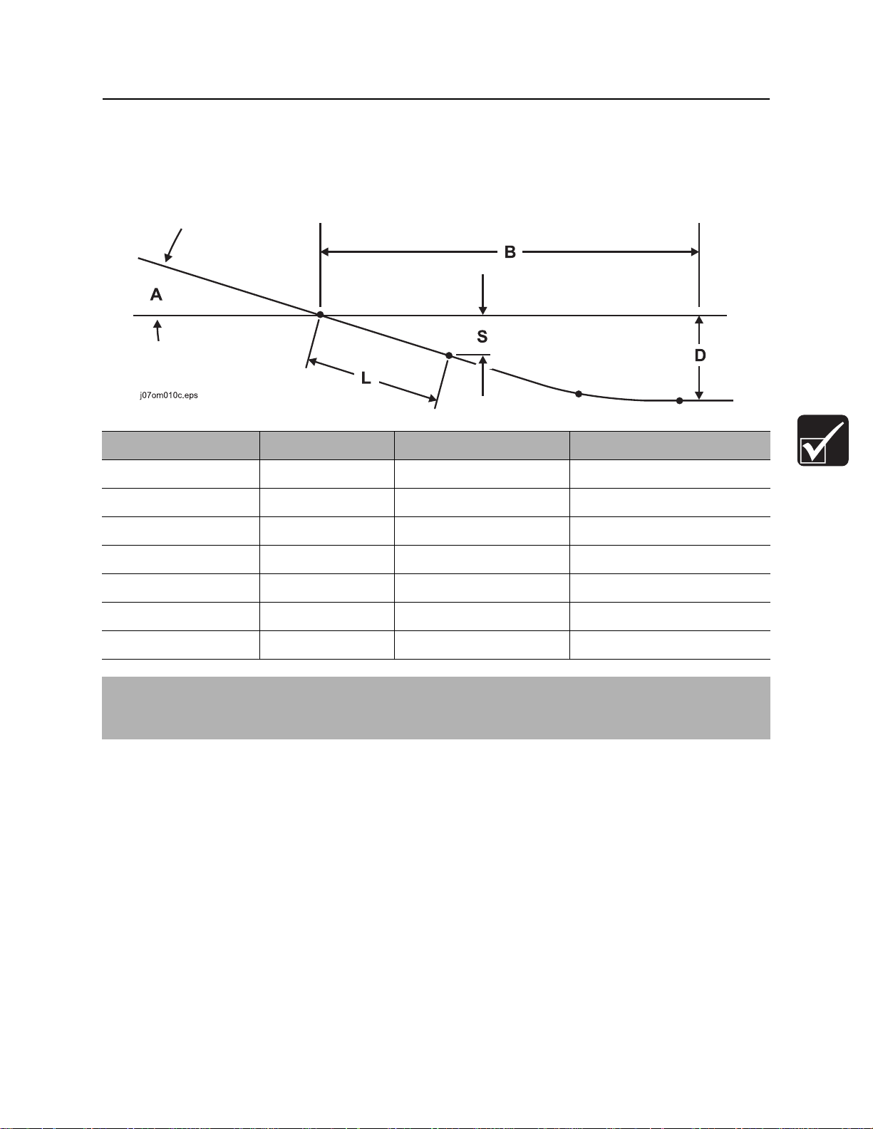
JT100/JT100 All Terrain Operator’s Manual Prepare - 91
Plan Bore Path
Bore Path Calculator - Power Pipe®
Entry pitch, setback, and minimum depth work together with bend limits to determine the bore path. To find
the setback (B) and entry pitch (A) that will take you to the desired minimum depth (D), use the chart
below.
Minimum depth (D) Entry pitch (A) Setback (B) Depth to begin steering (S)
6 ft 10 in (2.08 m) 11.3° / -20% 54 ft 6 in (16.61 m) 2 ft 10 in (0.86 m)
7 ft 11 in (2.41 m) 12.4° / -22% 58 ft 3 in (17.75 m) 3 ft 2 in (0.97 m)
9 ft 1 in (2.77 m) 13.5° / -24% 62 ft 0 in (18.90 m) 3 ft 5 in (1.04 m)
10 ft 3 in (3.12 m) 14.6° / -26% 65 ft 8 in (20.02 m) 3 ft 8 in (1.12 m)
11 ft 6 in (3.51 m) 15.6° / -28% 69 ft 4 in (21.13 m) 3 ft 11 in (1.19 m)
12 ft 10 in (3.91 m) 16.7° / -30% 72 ft 10 in (22.20 m) 4 ft 2 in (1.27 m)
14 ft 2 in (4.32 m) 17.7° / -32% 76 ft 4 in (23.27 m) 4 ft 5 in (1.35 m)
IMPORTANT: Numbers in table based on 205’ (62.5 m) minimum bend radius, and beacon housing,
EZ-Connect, transition sub, and half of first drill pipe (L, totaling 14’ 7” [4.45 m]) in the ground before
steering.
CMW
©
Page 93
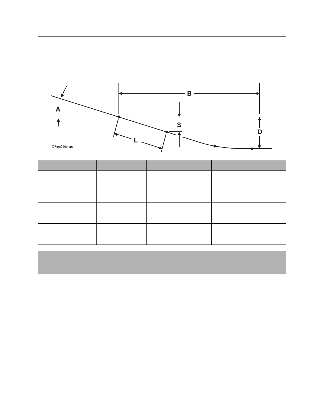
Prepare - 92 JT100/JT100 All Terrain Operator’s Manual
Plan Bore Path
Bore Path Calculator - Power Pipe® Forged
Entry pitch, setback, and minimum depth work together with bend limits to determine the bore path. To find
the setback (B) and entry pitch (A) that will take you to the desired minimum depth (D), use the chart
below.
Minimum depth (D) Entry pitch (A) Setback (B) Depth to begin steering (S)
5 ft 3 in (1.52 m) 10.0° / -18% 46 ft 10 in (14.27 m) 2 ft 3 in (0.69 m)
6 ft 0 in (1.83 m) 10.8° / -19% 49 ft 8 in (15.14 m) 2 ft 5 in (0.74 m)
6 ft 8 in (2.03 m) 11.7° / -21% 52 ft 5 in (15.98 m) 2 ft 8 in (0.81 m)
7 ft 6 in (2.29 m) 12.5° / -22% 55 ft 2 in (16.81 m) 2 ft 10 in (0.86 m)
8 ft 4 in (2.54 m) 13.3° / -24% 57 ft 11 in (11.65 m) 3 ft 0 in (0.91 m)
9 ft 2 in (2.79 m) 14.2° / -25% 60 ft 8 in (18.49 m) 3 ft 2 in (0.97 m)
10 ft 1 in (3.07 m) 15° / -27% 63 ft 5 in (19.33 m) 3 ft 4 in (1.02 m)
IMPORTANT: Numbers in table based on 197’ (60 m) minimum bend radius, and beacon housing,
EZ-Connect, transition sub, and half of first drill pipe (L, totaling 14’ 8” [4.47 m]) in the ground before
steering.
CMW
©
Page 94

JT100/JT100 All Terrain Operator’s Manual Prepare - 93
Plan Bore Path
Bore Path Calculator - All Terrain Pipe
Entry pitch, setback, and minimum depth work together with bend limits to determine the bore path. To find
the setback (B) and entry pitch (A) that will take you to the desired minimum depth (D), use the chart
below.
Minimum depth (D) Entry pitch (A) Setback (B) Depth to begin steering (S)
6 ft 7 in (2.01 m) 11.3° / -20% 53 ft 4 in (16.26 m) 2 ft 7 in (0.79 m)
7 ft 8 in (2.34 m) 12.4° / -22% 57 ft 1 in (17.40 m) 2 ft 10 in (0.86 m)
8 ft 9 in (2.67 m) 13.5° / -24% 60 ft 10 in (18.54 m) 3 ft 1 in (0.94 m)
10 ft 0 in (3.05 m) 14.6° / -26% 64 ft 6 in (19.66 m) 3 ft 4 in (1.02 m)
11 ft 2 in (3.40 m) 15.6° / -28% 68 ft 2 in (20.78 m) 3 ft 7 in (1.09 m)
12 ft 6 in (3.81 m) 16.7° / -30% 71 ft 9 in (21.87 m) 3 ft 10 in (1.17 m)
13 ft 10 in (4.22 m) 17.7° / -32% 75 ft 3 in (22.94 m) 4 ft 1 in (1.24 m)
IMPORTANT: Numbers in table based on 205’ (62.5 m) minimum bend radius, Rockmaster™
housing, 6.25-in bit, and half of first drill pipe (L, totaling 13.5’ [4.1 m]) in the ground before steering.
CMW
©
Page 95
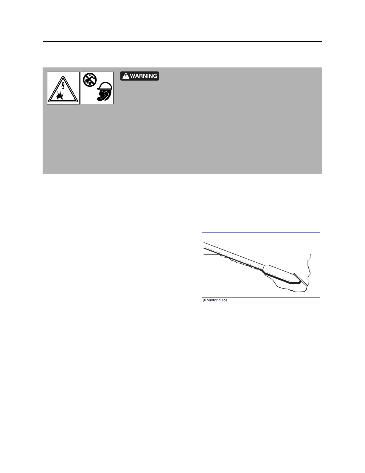
Prepare - 94 JT100/JT100 All Terrain Operator’s Manual
Prepare Jobsite
Prepare Jobsite
Jobsite hazards could cause death or serious injury. Use
correct equipment and work methods. Use and maintain proper safety
equipment.
To help avoid injury:
• If jobsite classification is in question or if the possibility of unmarked electric utilities exists, classify
jobsite as electric.
• Expose lines by hand before digging. Cutting high voltage cable can cause electrocution.
• All vegetation near operator’s station must be removed. Contact with trees, shrubs, or weeds during
electrical strike could result in electrocution.
Mark Bore Path
Mark your planned bore path and all located utility lines with flags or paint.
Prepare Entry Point
For bore to be successful, first pipe must be straight as
it enters the ground.
To help ensure that the first pipe does not bend, dig a
small starting hole so that the first pipe is drilled into a
vertical surface.
To prevent bending or straining pipe, position drilling
unit for straight entry.
CMW
©
Page 96

JT100/JT100 All Terrain Operator’s Manual Prepare - 95
Check Supplies and Prepare Equipment
Check Supplies and Prepare Equipment
Check Supplies
• receiver/transmitter or tracker with spare batteries
• beacons with new and spare batteries
• two-way radios with new and spare batteries
• hydraulic wrench (see “Hydratong Wrenches” on page 165)
• transition sub
• anchoring equipment and accessories
• bits, screens, nozzles (see “Downhole Tools” on page 160)
• adapters, pipe, beacon housings
• marking flags or paint
• water and additional hoses
• fuel
• drilling fluid additives (see “Drilling Fluid” on page 152)
• spare fuses
• keys
• backreamers, swivels, pulling devices (see “Backreamers” on page 162)
• wash down hose and spray gun
• duct tape
• spray lubricant
• tool joint compound (see “Recommended Lubricants/Service Key” on page 188)
• electrically insulating boots and gloves. Boots must have high tops and meet the electric hazard
protection requirements of ASTM F2413 when tested at 14,000 volts. Tuck legs of pants completely
inside boots.
• personal protective equipment, such as hard hat and safety glasses
• notepad and pencil
CMW
©
Page 97

Prepare - 96 JT100/JT100 All Terrain Operator’s Manual
Check Supplies and Prepare Equipment
Prepare Equipment
Fluid Levels
• fuel
• hydraulic fluid
• engine coolant
• battery charge
• engine oil
Condition and Function
• filters (air, oil, hydraulic)
• fluid pump
• couplers
• tires and tracks
• pumps and motors
• drilling fluid mixer
• hoses and valves
• water tanks
CMW
©
Page 98

JT100/JT100 All Terrain Operator’s Manual Prepare - 97
Check Supplies and Prepare Equipment
Select Drilling Mode
Three drilling setups are available with this unit:
• AT mode
• AT dirt mode
• JT mode
Select the best setup based on jobsite conditions.
Mode Situation used Downhole tools Capabilities
AT Rock, soft rock, other non-compressible
soils. Any other situation with difficult
steering because of hard soil
conditions.
AT
dirt
JT Soft or intermittent soft rock or other
Once drilling mode has been selected, configure drilling unit to match mode.
When one bore out of several can be
better or more quickly done with
conventional downhole tools. This bore
is such that changing to JT pipe is not
practical.
compressible soils.
• All Terrain drill pipe
• Rockmaster™ tool
• All Terrain drill pipe
• beacon housing
• transition sub
(p/n 400-1383)
• standard JT tools
• JT drill pipe
• standard JT tools
• 70,000 lb (311 kN)
of thrust
• dither
• inner rotation
• 70,000 lb (311 kN)
of thrust
• dither
• no inner rotation
• 70,000 lb (311 kN)
of thrust
• no dither
• no inner rotation
CMW
©
Page 99

Prepare - 98 JT100/JT100 All Terrain Operator’s Manual
Check Supplies and Prepare Equipment
Prepare Drilling Unit
AT Mode
• Verify unit has not been converted to JT mode. Ensure All Terrain saver sub, shuttle stop, roller, and
roller pin are installed.
• Inspect Rockmaster™ tool and select bit based on jobsite conditions.
• Use appropriate anchors for jobsite conditions.
• Load All Terrain pipe and pipe box onto unit.
• Move mode selector switch to AT position.
AT Dirt Mode
• Verify unit has not been converted to JT mode. Ensure All Terrain saver sub, shuttle stop, roller, and
roller pin are installed.
• Use transition sub (p/n 400-1383) between All Terrain pipe and beacon housing. Select soil bit based
on jobsite conditions.
• Use appropriate anchors for jobsite conditions.
• Load All Terrain pipe and pipe box onto unit.
• Move mode selector switch to AT DIRT position.
CMW
©
Page 100

JT100/JT100 All Terrain Operator’s Manual Prepare - 99
JT Mode
IMPORTANT: Use conversion kit (p/n 190-1548).
• Install saver sub, shuttle stop, roller, and roller pin for Mach 1 pipe.
• Use standard transition sub and beacon housing. Select soil bit based on jobsite conditions.
• Use auger type anchors.
• Load JT pipe and pipe box onto unit.
IMPORTANT: Do not put JT pipe into a large All Terrain pipe box. Pipe can jam and box can be
damaged. Use JT pipe box.
• Move mode selector switch to JT position.
Assemble Accessories
Fire Extinguisher
If required, mount a fire extinguisher near the power unit but away from possible points of ignition. The fire
extinguisher should always be classified for both oil and electric fires. It should meet legal and regulatory
requirements.
Lighting Kit
If you will need additional light, plug lighting kit into provided outlet. Contact your Ditch Witch® dealer for
further information.
CMW
©
 Loading...