

Page 1

FX50
Operator’s
Manual
CMW
®
Issue 1.0
053-2545
Page 2

FX50 Operator’s Manual Overview - 1
Overview
Chapter Contents
Serial Number Location . . . . . . . . . . . . . . . . . . . . . . 2
Intended Use . . . . . . . . . . . . . . . . . . . . . . . . . . . . . . . 2
Equipment Modification . . . . . . . . . . . . . . . . . . . . . 3
Unit Components . . . . . . . . . . . . . . . . . . . . . . . . . . . 3
Operator Orientation. . . . . . . . . . . . . . . . . . . . . . . . . 6
About This Manual . . . . . . . . . . . . . . . . . . . . . . . . . . 6
• Bulleted Lists. . . . . . . . . . . . . . . . . . . . . . . . . . . . . . . . . . . . . . . . . . . . . . 6
• Numbered Lists. . . . . . . . . . . . . . . . . . . . . . . . . . . . . . . . . . . . . . . . . . . . 6
CMW
Page 3
Overview - 2 FX50 Operator’s Manual
Serial Number Location
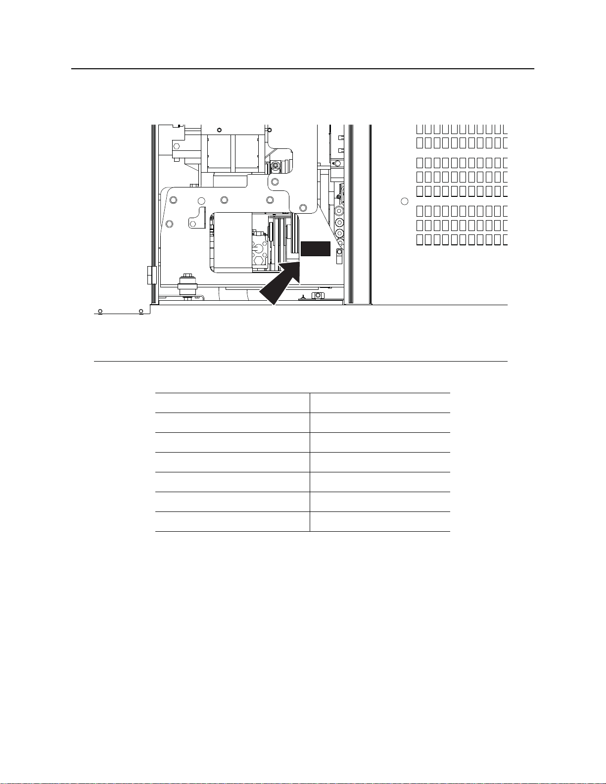
Serial Number Location
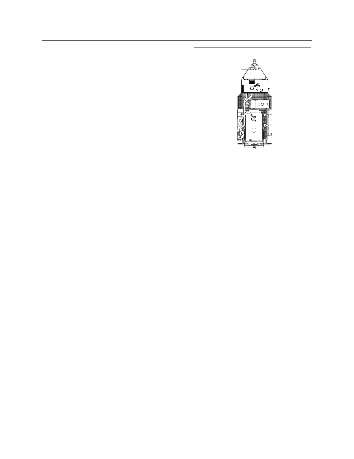
Record serial numbers and date of purchase in spaces provided. FX50 serial number is located as shown.
j36om071w.eps
Date of manufacture
Date of purchase
FX50 serial number (shown)
Engine serial number
Blower serial number
Water pump serial number
Trailer serial number
Intended Use
The FX50 is a self-contained vacuum excavation unit capable of vacuuming a wide variety of nonhazardous, non-flammable liquid and solid debris. It is designed to perform efficient soft excavation,
including exposing utilities for visual verification and/or potholing. The optional reverse flow system allows
for spoils transfer to another tank. The FX50 is intended for operation in ambient temperatures from 0° to
115°F (-18° to 46°C). Use in any other way is considered contrary to the intended use.
The FX50 should be operated, serviced, and repaired only by persons familiar with its particular
characteristics and acquainted with the relevant safety procedures.
CMW
Page 4
FX50 Operator’s Manual Overview - 3
j35om001h.eps
1
2
33445
6
7
8
10
9
11
12
Equipment Modification
Equipment Modification
This equipment was designed and built in accordance with applicable standards and regulations.
Modification of equipment could mean that it will no longer meet regulations and may not function properly
or in accordance with the operating instructions. Modification of equipment should only be made by
competent personnel possessing knowledge of applicable standards, regulations, equipment design
functionality/requirements and any required specialized testing.
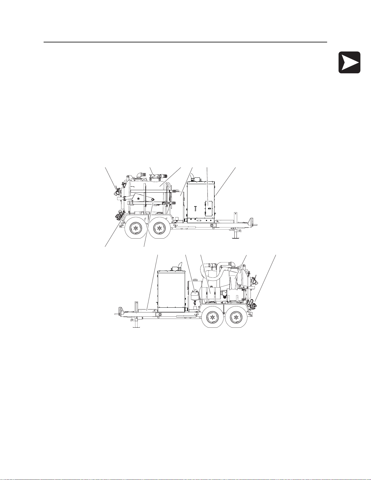
Unit Components
300-Gallon Tank
1
7
2
8
5
9
10
11
6
1312
j36om075w.eps
1. Inlet valve
2. Vacuum tank
3. Primary shut-off valve
4. Water tank
5. Operator’s station
6. Power unit
7. Hose reel
8. Potholing tools
9. Tool storage
10. Antifreeze tank
11. Vacuum filter
12. Cyclonic separator
13. Drain/outlet valve
CMW
Page 5
Overview - 4 FX50 Operator’s Manual
1
2
3
4
5
6
7
8
10
9
11
12
j
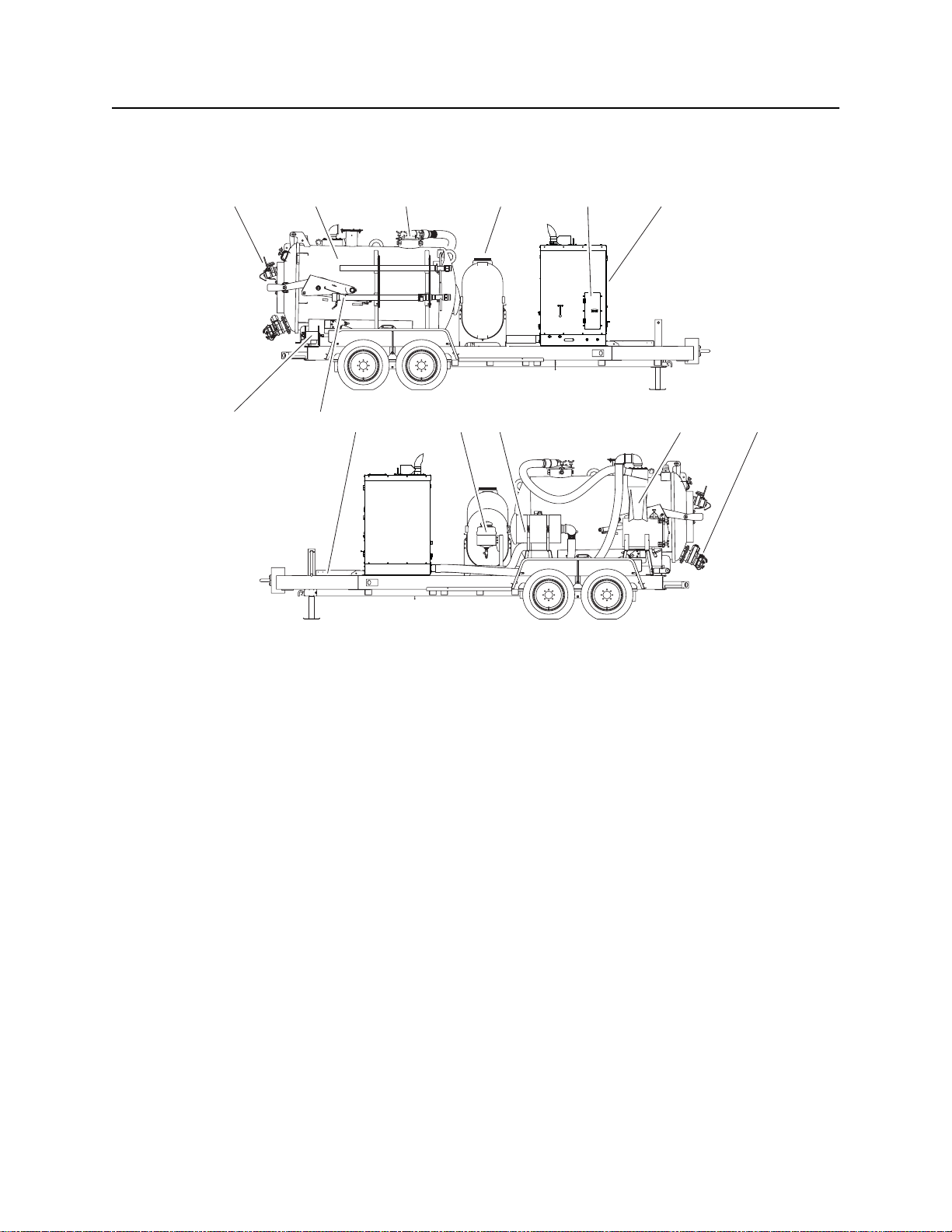
Unit Components
800-Gallon Tank
36om002w.eps
1
7
2
9
8
3
10
11
4
5
6
1312
1. Inlet valve
2. Vacuum tank
3. Primary shut-off valve
4. Water tank
5. Operator’s station
6. Power unit
7. Hose reel
8. Potholing tools
9. Tool storage
10. Antifreeze tank
11. Vacuum filter
12. Cyclonic separator
13. Drain/outlet valve
CMW
Page 6
FX50 Operator’s Manual Overview - 5
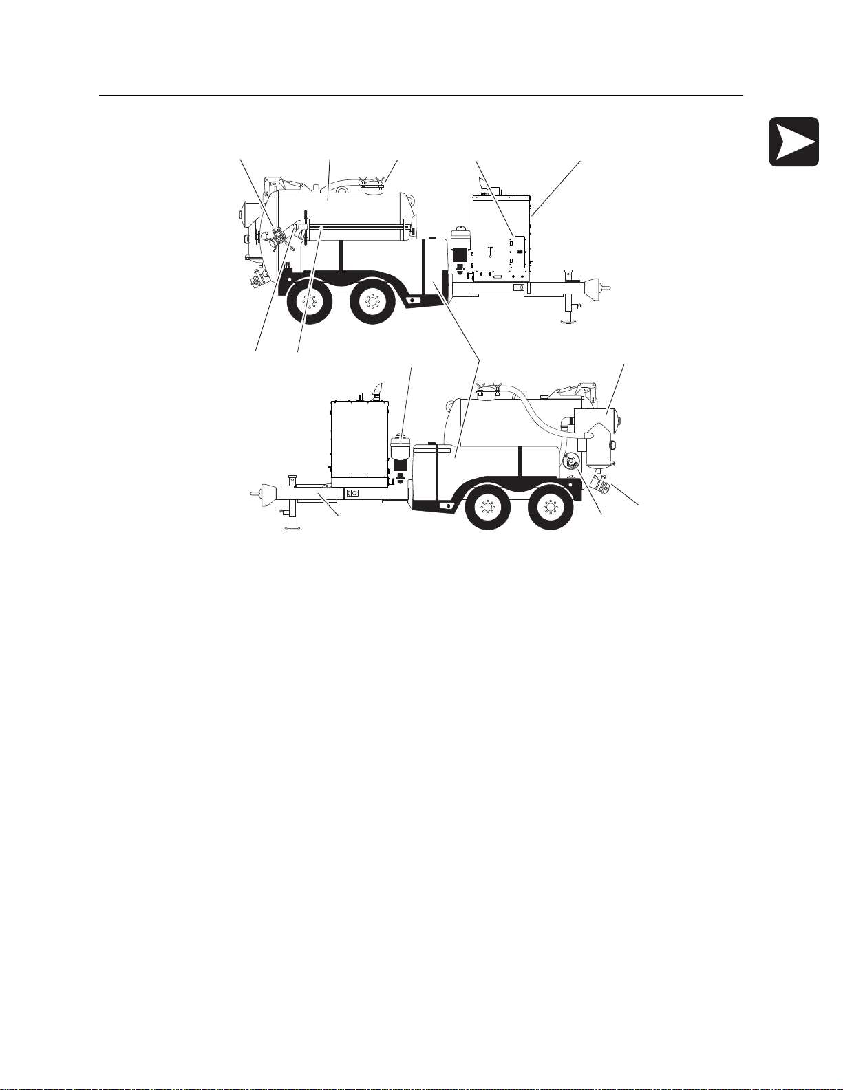
Unit Components
1200-Gal (4542-L)Tank
234 51
j36om077w.eps
1. Inlet valve
2. Vacuum tank
3. Primary shutoff valve
4. Operator’s station
5. Power unit
6. Potholing tools
7. Water lance
76
8 10
9
11
1213
8. Antifreeze tank
9. Water tanks
10. Vacuum filter/secondary shutoff valve
11. Drain/Outlet valve
12. Hose reel
13. Tool storage
CMW
Page 7
Overview - 6 FX50 Operator’s Manual
1
2
3
4
Operator Orientation
Operator Orientation
1. Front of unit
2. Right of unit
Right and left sides of machine are determined by
facing towing vehicle.
3. Rear of unit
4. Left of unit
4
j36om003w.eps
1
2
3
About This Manual
This manual contains information for the proper use of this machine. See Operation Overview for basic
operating procedures. Cross references such as “See page 50” will direct you to detailed procedures.
Bulleted Lists
Bulleted lists provide helpful or important information or contain procedures that do not have to be
performed in a specific order.
Numbered Lists
Numbered lists contain illustration callouts or list steps that must be performed in order.
CMW
Page 8

FX50 Operator’s Manual Foreword - 7
Reporting Safety Defects
Foreword
This manual is an important part of your equipment. It provides safety information and operation
instructions to help you use and maintain your Ditch Witch equipment.
Read this manual before using your equipment. Keep it with the equipment at all times for future reference.
If you sell your equipment, be sure to give this manual to the new owner.
If you need a replacement copy, contact your Ditch Witch dealer. If you need assistance in locating a
dealer, visit our website at www.ditchwitch.com or write to the following address:
The Charles Machine Works, Inc.
Attn: Marketing Department
PO Box 66
Perry, OK 73077-0066
USA
The descriptions and specifications in this manual are subject to change without notice. The Charles
Machine Works, Inc. reserves the right to improve equipment. Some product improvements may have
taken place after this manual was published. For the latest information on Ditch Witch equipment, see your
Ditch Witch dealer.
Thank you for buying and using Ditch Witch equipment.
Reporting Safety Defects
If you believe that your vehicle has a defect which could cause a crash or could cause injury or death, you
should immediately inform the National Highway Traffic Safety Administration (NHTSA) in addition to
notifying The Charles Machine Works, Inc, Attn: Product Safety Coordinator.
If NHTSA receives similar complaints, it may open an investigation, and if it finds that a safety defect exists
in a group of vehicles, it may order a recall and remedy campaign. However, NHTSA cannot become
involved in any individual problems between you, your Ditch Witch dealer, or The Charles Machine Works,
Inc.
To contact NHTSA you may either call the Auto Safety Hotline toll-free at 1-800-424-9393 (366-0123 in
Washington, DC area) or write to:
NHTSA
U.S. Department of Transportation
400 7th Street SW (NSA-11)
Washington, DC 20590
You can also obtain other information about motor vehicle safety from the Hotline.
CMW
Page 9

Foreword - 8 FX50 Operator’s Manual
Works, Inc.
FX50
Operator’s Manual
Issue number 1.0/OM-9/12
Part number 053-2545
Copyright 2012
by The Charles Machine Works, Inc.
, Ditch Witch, and CMW are registered trademarks of The Charles Machine
U.S. patents pending.
CMW
Page 10
FX50 Operator’s Manual Contents - 9
Contents
Overview
machine serial number, information about the type of work this machine is designed
to perform, basic machine components, and how to use this manual
Foreword
part number, revision level, and publication date of this manual, and factory contact
information
Safety
machine safety alerts and emergency procedures
Controls
machine controls, gauges, and indicators and how to use them
Operation Overview
an overview for completing a job with this machine: planning, setting up, vacuuming,
potholing, and restoring the jobsite; with cross references to detailed procedures
Prepare
procedures for inspecting and classifying the jobsite, and preparing the jobsite for
work
Transport
procedures for lifting and hauling
1
7
11
21
37
41
47
Vacuum and Pothole
procedures for removing debris and potholing utility locations
Complete the Job
procedures for restoring the jobsite and rinsing and storing equipment
Service
service intervals and instructions for this machine including lubrication, replacement
of wear items, and basic maintenance
Specifications
machine specifications including weights, measurements, power ratings, and fluid
capacities
Support
the warranty policy for this machine, and procedures for obtaining warranty
consideration and training
51
69
73
115
127
CMW
Page 11

Contents - 10 FX50 Operator’s Manual
Service Record
a record of major service performed on the machine
Appendix
Information regarding tire safety
131
133
CMW
Page 12

FX50 Operator’s Manual Safety - 11
Safety
Chapter Contents
Guidelines . . . . . . . . . . . . . . . . . . . . . . . . . . . . . . . . 12
Safety Alert Classifications . . . . . . . . . . . . . . . . . . 13
Safety Alerts . . . . . . . . . . . . . . . . . . . . . . . . . . . . . . 14
Emergency Procedures . . . . . . . . . . . . . . . . . . . . . 17
• Electric Strike Description. . . . . . . . . . . . . . . . . . . . . . . . . . . . . . . . . . . 17
• If an Electric Line is Damaged . . . . . . . . . . . . . . . . . . . . . . . . . . . . . . . 18
• If a Gas Line is Damaged . . . . . . . . . . . . . . . . . . . . . . . . . . . . . . . . . . . 19
• If a Fiber Optic Cable is Damaged . . . . . . . . . . . . . . . . . . . . . . . . . . . . 20
• If Machine Catches on Fire. . . . . . . . . . . . . . . . . . . . . . . . . . . . . . . . . . 20
CMW
Page 13

Safety - 12 FX50 Operator’s Manual
Guidelines
Guidelines
Follow these guidelines before operating any jobsite equipment:
• Complete proper training and read operator’s manual before using equipment.
• Contact your local One-Call (811 in USA) or the One-Call referral number (888-258-0808 in USA and
Canada) to have underground utilities located before digging. Also contact any utilities that do not
participate in the One-Call service.
• Classify jobsite based on its hazards and use correct tools and machinery, safety equipment, and work
methods for jobsite.
• Mark jobsite clearly and keep spectators away.
• Wear personal protective equipment.
• Review jobsite hazards, safety and emergency procedures, and individual responsibilities with all
personnel before work begins. Safety videos are available from your Ditch Witch dealer.
• Replace missing or damaged safety shields and safety signs.
• Use equipment carefully. Stop operation and investigate anything that does not look or feel right.
• Do not operate unit where flammable gas may be present.
• Contact your Ditch Witch dealer if you have any question about operation, maintenance, or equipment
use.
CMW
Page 14

FX50 Operator’s Manual Safety - 13
Safety Alert Classifications
Safety Alert Classifications
These classifications and the icons defined on the following pages work together to alert you to situations
which could be harmful to you, jobsite bystanders or your equipment. When you see these words and
icons in the book or on the machine, carefully read and follow all instructions. YOUR SAFETY IS AT
STAKE.
Watch for the three safety alert levels: DANGER, WARNING and CAUTION. Learn what each level
means.
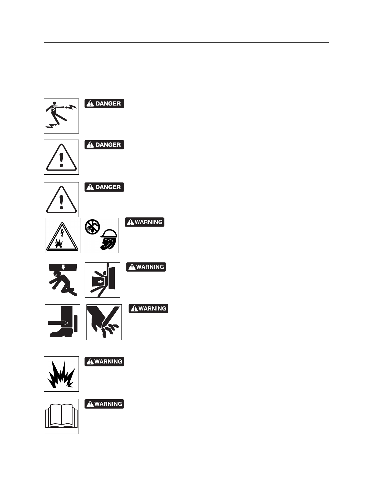
indicates a hazardous situation that, if not avoided, will result in death or serious injury.
This signal word is to be limited to the most extreme situations.
indicates a hazardous situation that, if not avoided, could result in death or serious injury.
indicates a hazardous situation that, if not avoided, could result in minor or moderate
injury.
Watch for two other words: NOTICE and IMPORTANT.
NOTICE indicates information considered important, but not hazard-related (e.g., messages relating to
property damage).
IMPORTANT can help you do a better job or make your job easier in some way.
CMW
Page 15
Safety - 14 FX50 Operator’s Manual
Safety Alerts
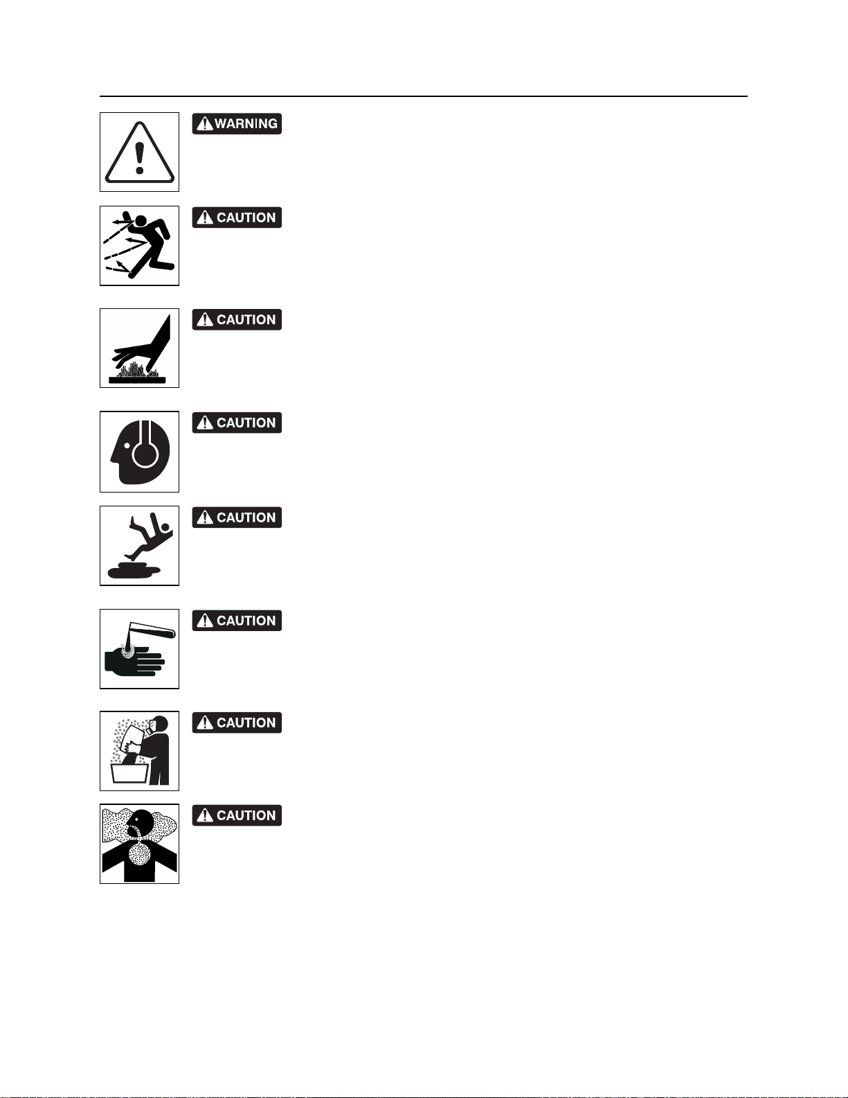
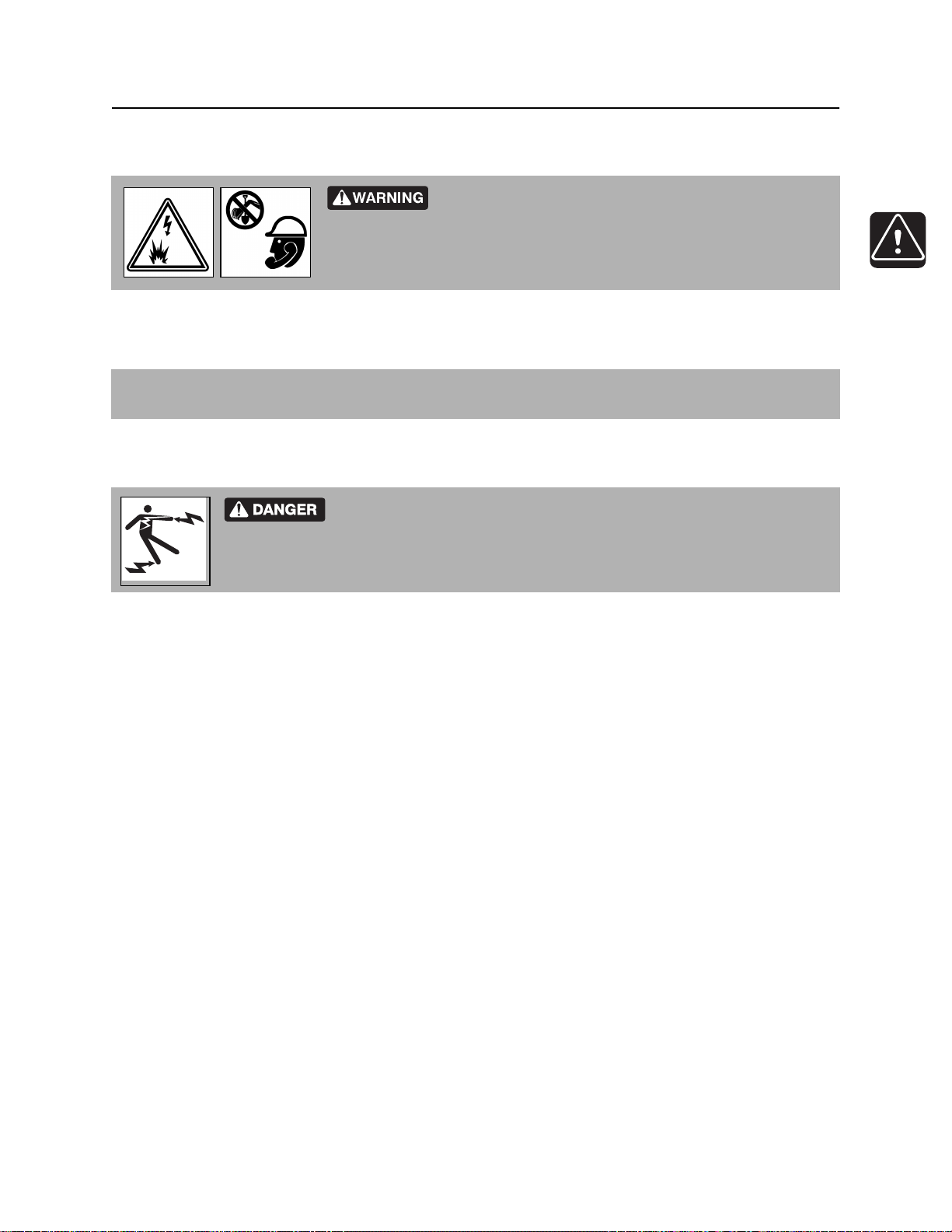
Safety Alerts
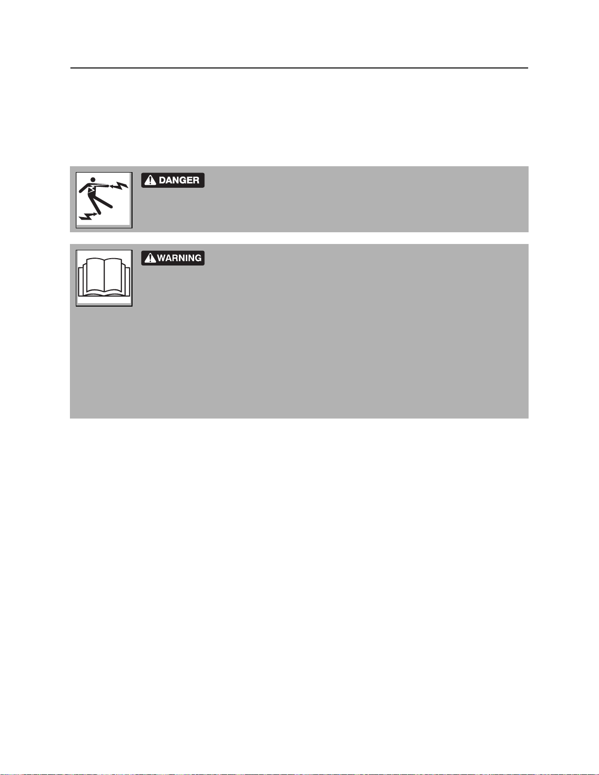
Electric shock. Contacting electric lines will cause death or serious injury.
Know location of lines and stay away.
Confined space will cause suffocation. Use proper procedures for entering
or stay away.
Vacuum will suffocate. Maintain distance between face and vacuum inlets.
correct equipment and work methods. Use and maintain proper safety
equipment.
proper procedures and equipment or stay away.
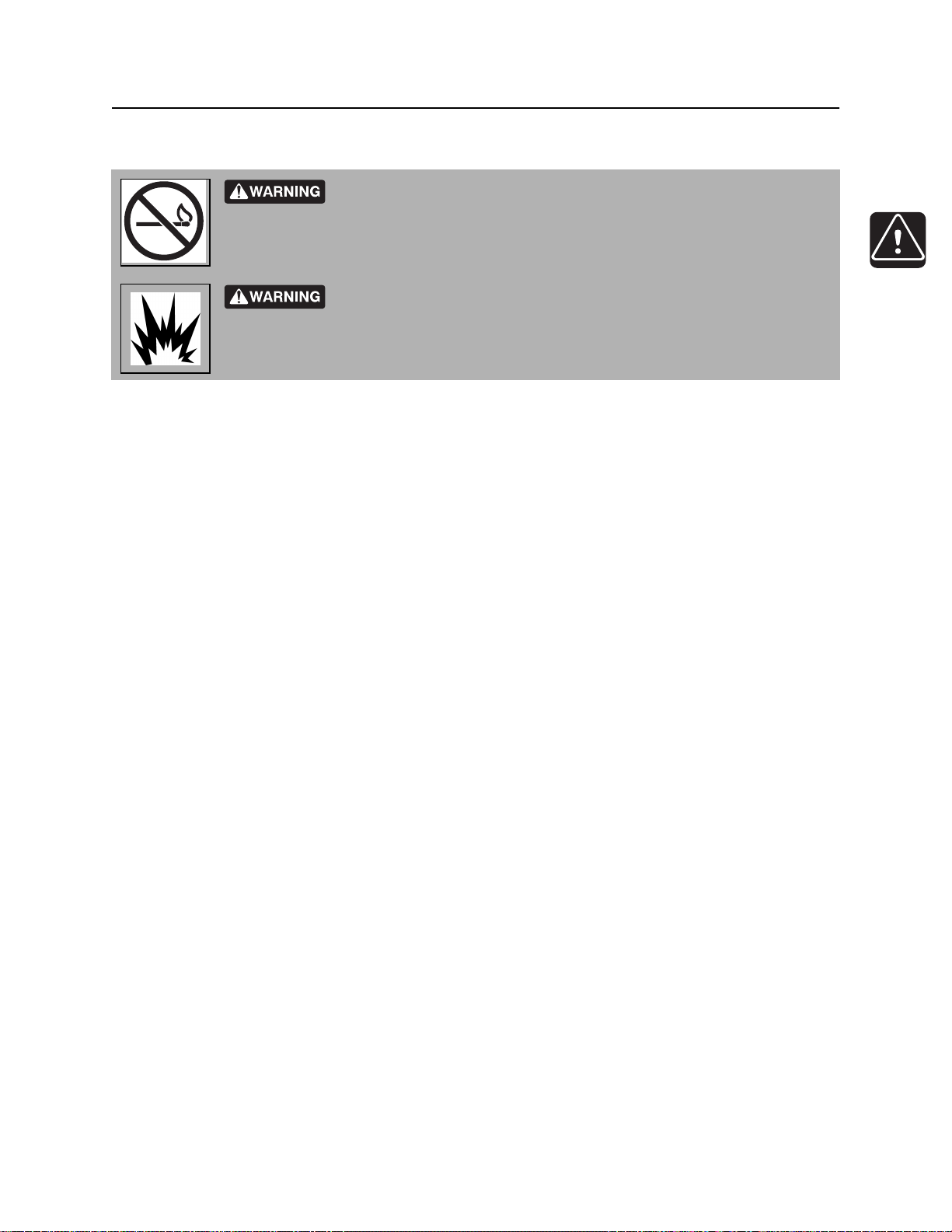
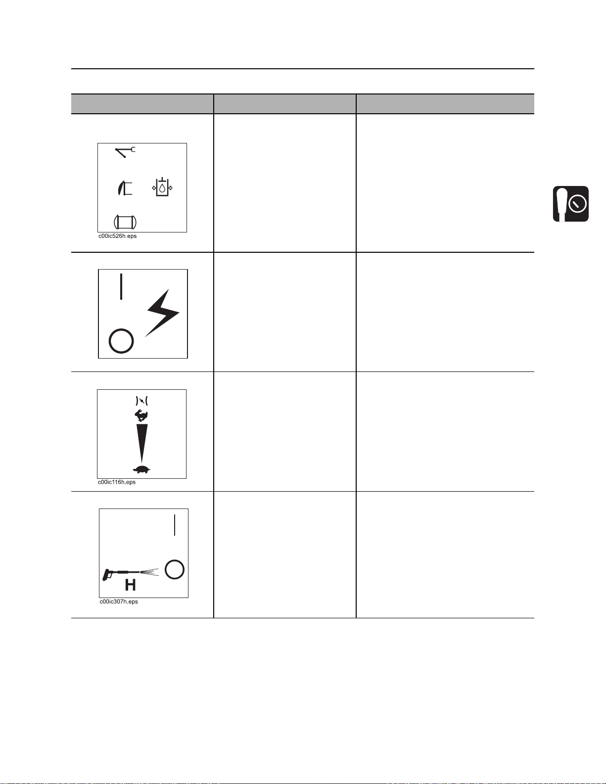
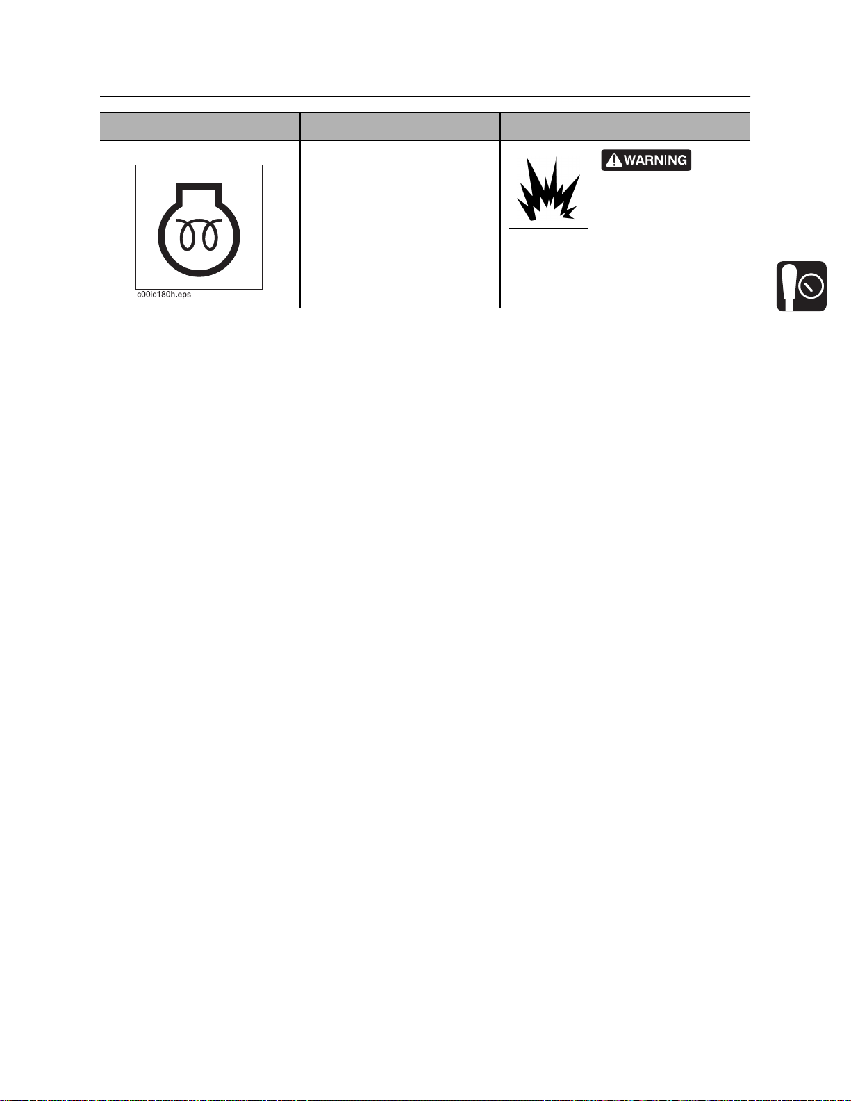
Explosion possible. Serious injury or equipment damage could occur.
Follow directions carefully.
Jobsite hazards could cause death or serious injury. Use
Crushing weight could cause death or serious injury. Use
Moving parts could cut off hand or foot. Stay away.
CMW
Incorrect procedures could result in death, injury, or property damage.
Learn to use equipment correctly.
Page 16
FX50 Operator’s Manual Safety - 15
Safety Alerts
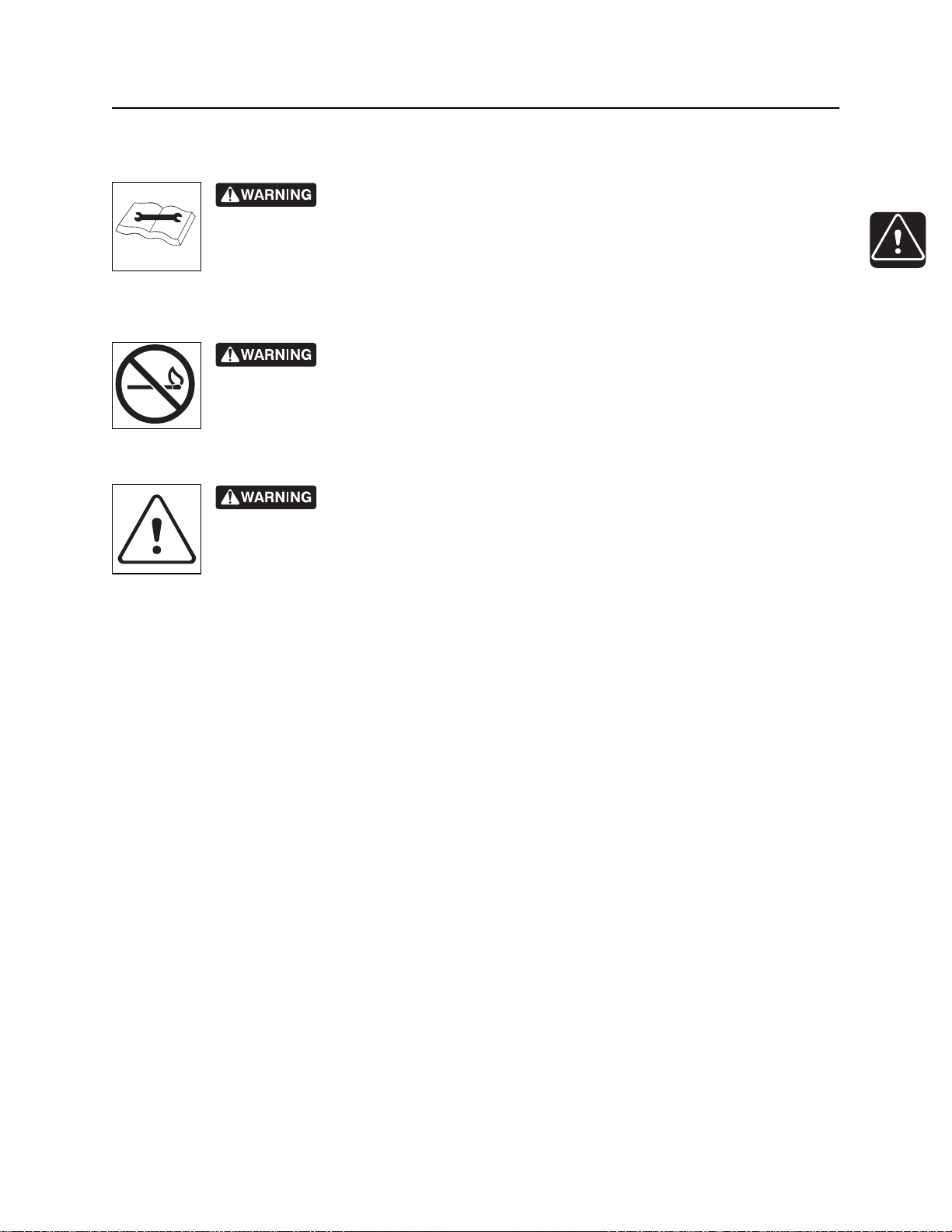
Improper control function could cause death or serious injury. If control does
not work as described in instructions, stop machine and have it serviced.
Fire or explosion possible. Fumes could ignite and cause burns. No
smoking, no flame, no spark.
Moving traffic - hazardous situation. Death or serious injury could result.
Avoid moving vehicles, wear high visibility clothing, post appropriate warning signs.
CMW
Page 17
Safety - 16 FX50 Operator’s Manual
Safety Alerts
Hot pressurized cooling system fluid could cause serious burns. Allow to
cool before servicing.
Flying objects may cause injury. Wear hard hat and safety glasses.
Hot parts may cause burns. Do not touch until cool.
Exposure to high noise levels may cause hearing loss. Wear hearing
protection.
Fall possible. Slips or trips may result in injury. Keep area clean.
Battery acid may cause burns. Avoid contact.
Improper handling or use of chemicals may result in illness, injury, or
equipment damage. Follow instructions on labels and in material safety data sheets
(MSDS).
Breathing crystalline silica dust may cause lung disease. Cutting, drilling, or
working materials such as concrete, sand, or rock containing quartz may result in exposure
to silica dust. Use dust control methods or appropriate breathing protection when exposed
to silica dust.
CMW
Page 18
FX50 Operator’s Manual Safety - 17
Emergency Procedures
Emergency Procedures
Jobsite hazards could cause death or serious injury. Use
correct equipment and work methods. Use and maintain proper safety
equipment.
Before operating any equipment, review emergency procedures and check that all safety precautions have
been taken.
EMERGENCY SHUTDOWN - Turn ignition switch to stop position or push remote engine stop button (if
equipped).
Electric Strike Description
Electric shock. Contacting electric lines will cause death or serious injury.
Know location of lines and stay away.
When working near electric cables, remember the following:
• Electricity follows all paths to ground, not just path of least resistance.
• Pipes, hoses, and cables will conduct electricity back to all equipment.
• Low voltage current can injure or kill. Many work-related electrocutions result from contact with less
than 440 volts.
Most electric strikes are not noticeable, but indications of a strike include:
• power outage
• smoke
• explosion
• popping noises
• arcing electricity
If any of these occur, assume an electric strike has occurred.
CMW
Page 19

Safety - 18 FX50 Operator’s Manual
Emergency Procedures
If an Electric Line is Damaged
If you suspect an electric line has been damaged and you are on truck or trailer, DO NOT MOVE.
Remain on truck or trailer and take the following actions. The order and degree of action will depend on the
situation.
• Warn people nearby that an electric strike has occurred. Instruct them to leave the area and contact
utility.
• Do not allow anyone into area until given permission by utility company.
• Do not allow anyone to touch equipment.
If you suspect an electric line has been damaged and you are off truck or trailer, DO NOT TOUCH
EQUIPMENT. Take the following actions. The order and degree of action will depend on the situation.
• LEAVE AREA. The ground surface may be electrified so take small shuffle steps with feet close
together to reduce the hazard of being shocked from one foot to the other.
• Contact utility company to shut off power.
• Do not return to area or allow anyone into area until given permission by utility company.
CMW
Page 20
FX50 Operator’s Manual Safety - 19
Emergency Procedures
If a Gas Line is Damaged
Fire or explosion possible. Fumes could ignite and cause burns. No
smoking, no flame, no spark.
Explosion possible. Serious injury or equipment damage could occur.
Follow directions carefully.
If you suspect a gas line has been damaged, take the following actions. The order and degree of action will
depend on the situation.
• Immediately shut off engine(s), if this can be done safely and quickly.
• Remove any ignition source(s), if this can be done safely and quickly.
• Warn others that a gas line has been cut and that they should leave the area.
• Leave jobsite as quickly as possible.
• Immediately call your local emergency phone number and utility company.
• If jobsite is along street, stop traffic from driving near jobsite.
• Do not return to jobsite until given permission by emergency personnel and utility company.
CMW
Page 21

Safety - 20 FX50 Operator’s Manual
Emergency Procedures
If a Fiber Optic Cable is Damaged
Do not look into cut ends of fiber optic or unidentified cable. Vision damage can occur.
If Machine Catches on Fire
Perform emergency shutdown procedure and then take the following actions. The order and degree of
action will depend on the situation.
• Immediately move battery disconnect switch (if equipped and accessible) to disconnect position.
• If fire is small and fire extinguisher is available, attempt to extinguish fire.
• If fire cannot be extinguished, leave area as quickly as possible and contact emergency personnel.
CMW
Page 22

FX50 Operator’s Manual Controls - 21
Controls
Chapter Contents
Power Pack . . . . . . . . . . . . . . . . . . . . . . . . . . . . . . . 22
• Controls and Connectors . . . . . . . . . . . . . . . . . . . . . . . . . . . . . . . . . . . 22
• Gauges and Indicators . . . . . . . . . . . . . . . . . . . . . . . . . . . . . . . . . . . . . 25
• Miscellaneous . . . . . . . . . . . . . . . . . . . . . . . . . . . . . . . . . . . . . . . . . . . 28
Tank . . . . . . . . . . . . . . . . . . . . . . . . . . . . . . . . . . . . . 30
• Tethered Controller . . . . . . . . . . . . . . . . . . . . . . . . . . . . . . . . . . . . . . . 30
• Machine Controls . . . . . . . . . . . . . . . . . . . . . . . . . . . . . . . . . . . . . . . . . 31
Vacuum Boom (optional) . . . . . . . . . . . . . . . . . . . . 34
CMW
Page 23
Controls - 22 FX50 Operator’s Manual
Power Pack
Power Pack
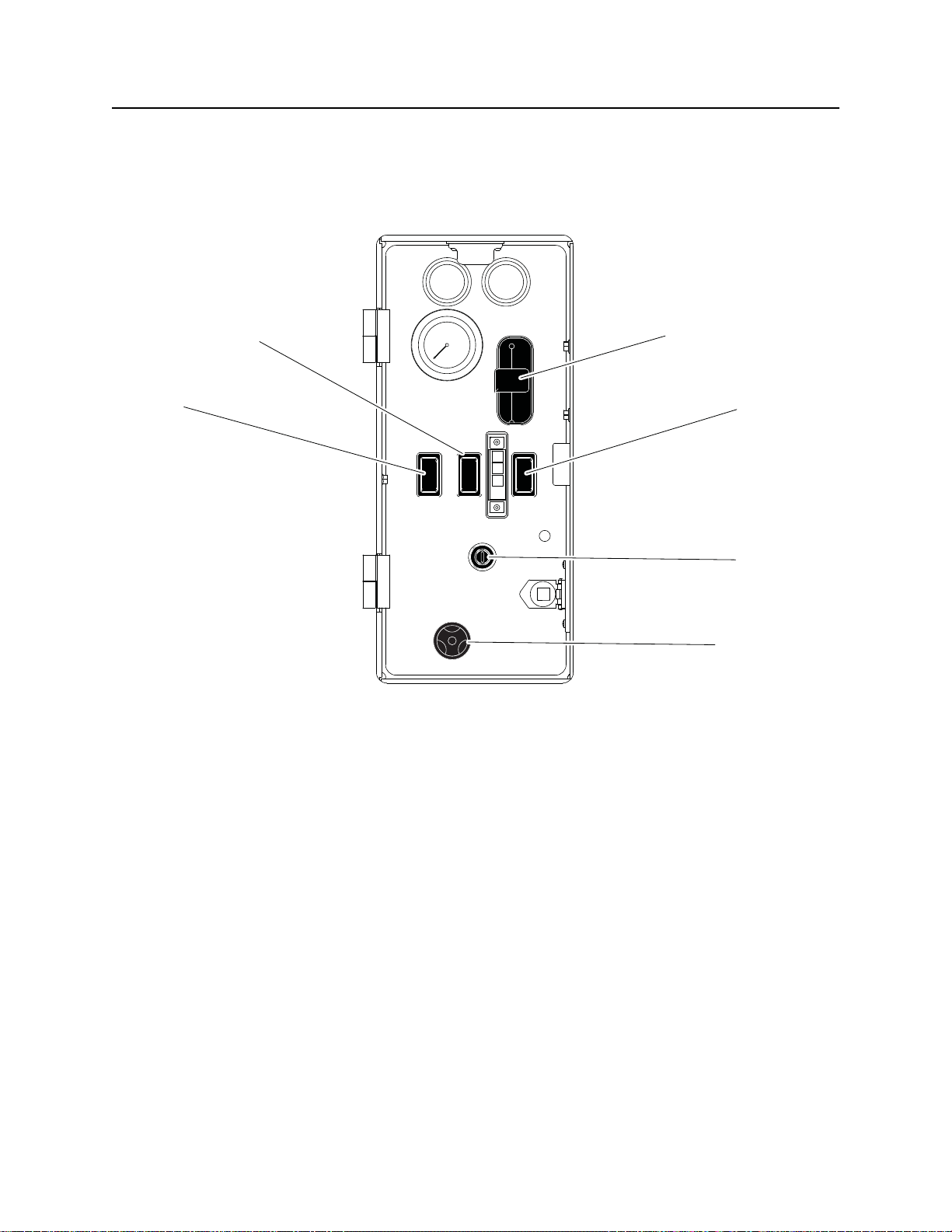
Controls and Connectors
23
1
j36om016w.eps
1. Hydraulic function switch
2. Auxiliary outlet switch
3. Throttle
4
5
6
4. Water pressure switch
5. Ignition switch
6. Water pressure control
CMW
Page 24
FX50 Operator’s Manual Controls - 23
Power Pack
Item Description Notes
1. Hydraulic function
switch
2. Auxiliary outlet switch To turn on, press top.
c00ic061t.eps
3. Throttle To increase engine speed,
To direct hydraulic power to
the optional boom function,
press top.
To direct hydraulic power to
the door function, move to
center position.
To direct hydraulic power to
the tank tilt function, press
bottom.
To turn off, press bottom.
push up.
IMPORTANT: Keep switch in off
position unless in use.
To decrease engine speed,
pull down.
4. Water pressure switch To turn on water pump, press
top.
To turn off water pump, move
to center position.
To bypass low water
indication, press bottom.
Water pump will operate for
60 seconds.
Use bypass to feed antifreeze into
system when freshwater tank is
empty. See “Add Antifreeze” on
page 70.
CMW
Page 25
Controls - 24 FX50 Operator’s Manual
Power Pack
Item Description Notes
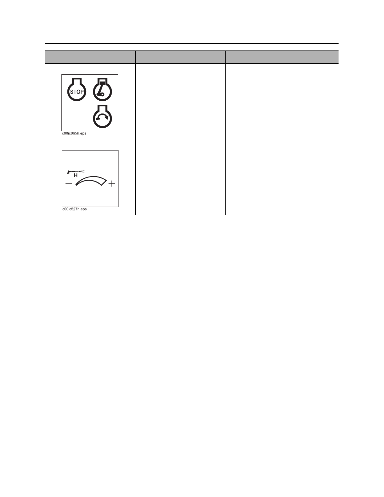
5. Ignition switch To start engine, insert key and
turn clockwise.
To stop engine, turn key
counterclockwise.
6. Water pressure control To increase water pressure,
turn clockwise.
To decrease water pressure,
turn counterclockwise.
IMPORTANT:
• When engine is on, blower
operates and vacuum is present
at tank inlet.
• All indicators should light briefly at
startup.
CMW
Page 26
FX50 Operator’s Manual Controls - 25
Power Pack
Gauges and Indicators
23
1
4
5
6
1. Water pressure gauge
2. Fuel gauge
3. Hourmeter
Item Description Notes
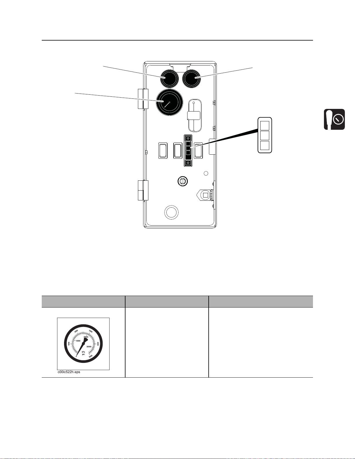
1. Water pressure gauge Displays water pressure
when water pressure switch
is on and water lance is in
use.
4. Engine oil pressure indicator
5. Engine oil temperature indicator
6. Cold start wait indicator
CMW
Page 27
Controls - 26 FX50 Operator’s Manual
Power Pack
Item Description Notes
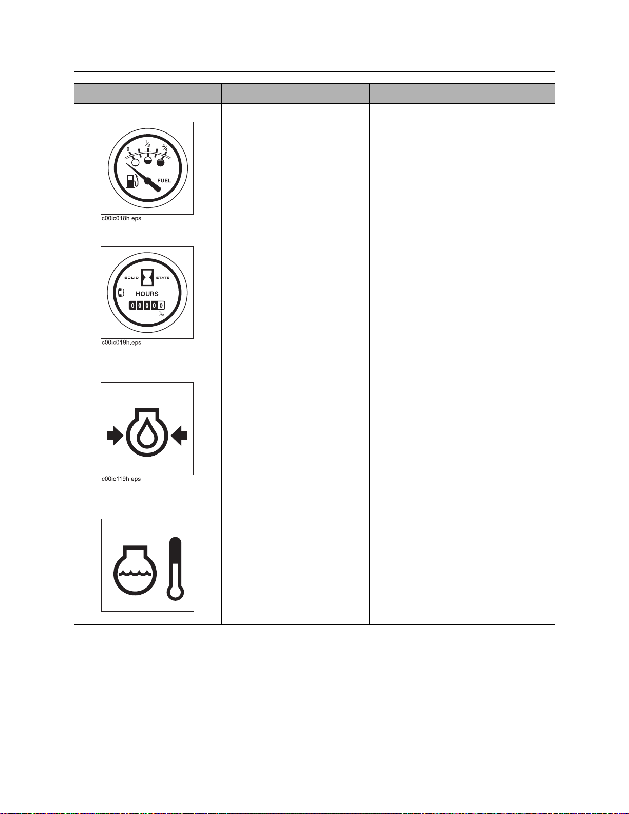
2. Fuel gauge Displays fuel level in tank. NOTICE: Use low sulfur or ultra low
sulfur diesel fuel only.
In temperatures below 32° F
(0° C), use #1 diesel fuel.
Tank holds 19 gal (72 L).
3. Hourmeter Displays engine operating
time.
4. Engine oil pressure
indicator
Indicates engine oil pressure
is too low.
Also lights briefly when
engine is started.
4. Engine oil temperature
indicator
Indicates engine oil
temperature is too high.
Hourmeter runs when ignition switch
is on.
Use these times to schedule service.
Engine will stop.
1. Check oil level.
2. Check for leaks before starting
engine.
3. If pressure is still low, consult
engine manual.
Engine will stop.
1. Let engine cool.
CMW
2. Check fan belt tension.
3. Check engine oil level.
4. Check cooling fins for dirt and
debris.
c00ic120h.eps
Page 28
FX50 Operator’s Manual Controls - 27
Power Pack
Item Description Notes
5. Cold start wait indicator Indicates intake air preheater
is operating.
Wait until light goes off before
starting engine. See “Cold
Start Procedure” on page 57.
Explosion possible.
Serious injury or
equipment damage
could occur.
To help avoid injury: do not use
ether or starting fluid
CMW
Page 29
Controls - 28 FX50 Operator’s Manual
Power Pack
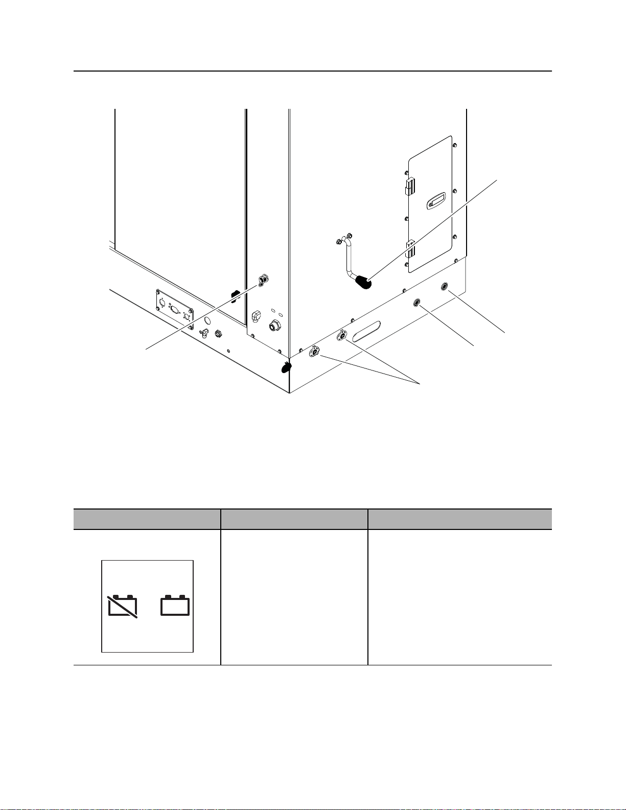
Miscellaneous
2
3
1
4
1. Battery disconnect
2. Flow direction control (optional)
3. Hydraulic fluid drain
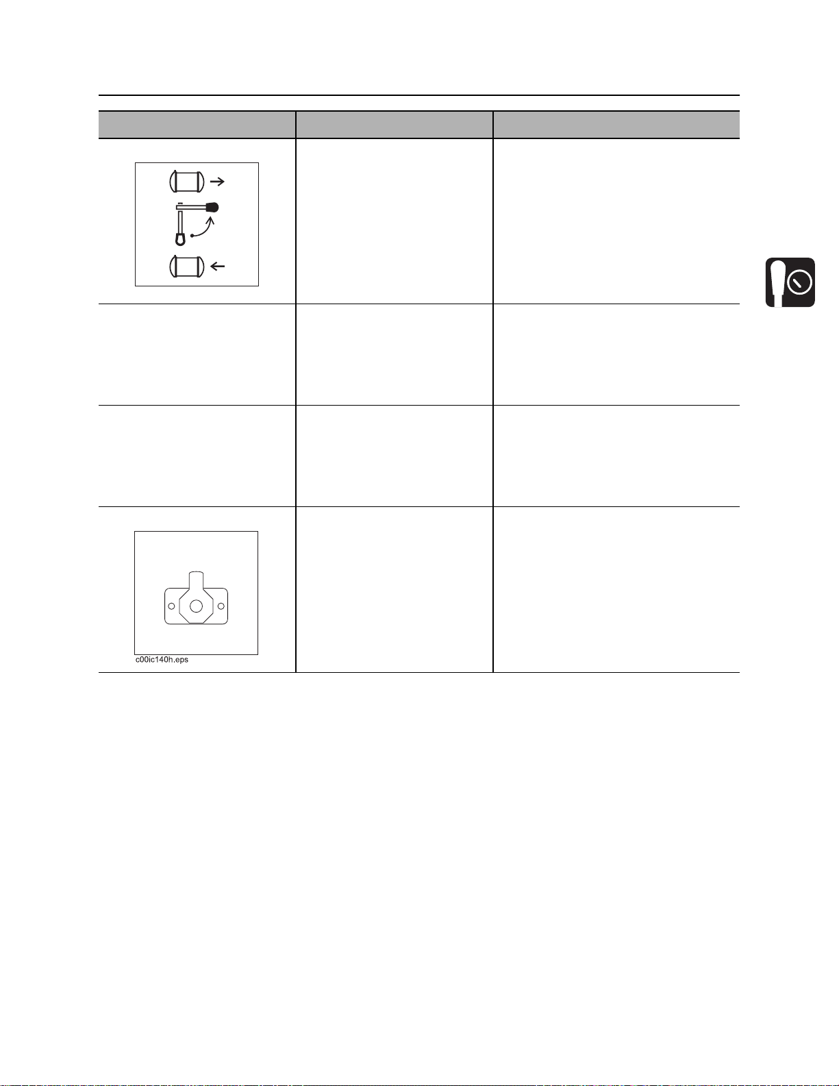
Item Description Notes
1. Battery disconnect
switch
_
c00ic063t.eps
+
_
+
To connect, turn clockwise.
To disconnect, turn
counterclockwise.
4. Engine oil drain
5. Auxiliary outlets
IMPORTANT: Use battery disconnect
switch when servicing, welding, and
during long-term storage.
5
CMW
Page 30
FX50 Operator’s Manual Controls - 29
Power Pack
Item Description Notes
2. Flow direction control To operate in reverse flow
mode, turn counterclockwise.
To operate in vacuum mode,
turn clockwise.
c00ic605h.eps
3. Hydraulic fluid drain To drain:
• Remove plug.
• Replace plug when drain
pan is empty.
4. Engine oil drain To drain:
• Remove plug.
• Replace plug when drain
pan is empty.
5. Auxiliary outlets To operate work lights or
other 12V devices, plug into
outlet.
Use reverse flow to unload tank
contents to another tank. Operate in
reverse flow mode only when drain/
outlet valve is open.
Outlet has power only when ignition
switch is on.
Device can be turned on and
off with auxiliary power
switch.
CMW
Page 31

Controls - 30 FX50 Operator’s Manual
Tank
Tank
Tethered Controller
1
UP
DOWN
j36om018w.eps
Item Description Notes
1. Up To raise tank, set hydraulic
function switch to the tank
position and press UP.
To open tank door, set
U P
c00ic064t.eps
hydraulic function switch to
the door position and press
UP.
Note: The vacuum boom uses a
different tethered controller. See
page 34.
2
2. Down To lower tank, set hydraulic
function switch to the tank
position and press DOWN.
To close tank door, set
DOWN
c00ic065t.eps
CMW
hydraulic function switch to
the door position and press
DOWN.
Page 32

FX50 Operator’s Manual Controls - 31
1
2
3
4
5
6
Tank
Machine Controls
j36om005w.eps
1
4
2
5
3
6
7
8
1. Inlet valve
2. Water tank drain
3. Water tank supply valve
4. Vacuum gauge
Item Description Notes
1. Inlet valve To close valve (stop suction),
rotate up.
To open valve (start suction),
rotate down.
5. Antifreeze tank supply valve
6. Flow direction control (optional)
7. Drain/Outlet valve
8. Reverse flow gauge (optional)
CMW
Page 33

Controls - 32 FX50 Operator’s Manual
Tank
Item Description Notes
2. Water tank drain To drain tank, open valve.
Close valve when tank is
empty.
c00ic604h.eps
3. Water tank supply valve To open valve (send water
from the water tank through
the pump and water lance),
rotate counterclockwise.
To close valve (stop water
flow), rotate clockwise.
c00ic603h.eps
4. Vacuum gauge Displays blower vacuum
reading in inches of mercury.
Vacuum relief valve opens
when vacuum reaches 16”
(406 mm).
5. Antifreeze tank supply
valve
To open valve (send
antifreeze through pump and
water lance), rotate
counterclockwise.
IMPORTANT: Water tank supply
valve or antifreeze supply valve must
be open when pump is running or
pump will be damaged.
IMPORTANT: Water tank supply
valve or antifreeze supply valve must
be open when pump is running or
pump will be damaged.
CMW
To close valve (stop
antifreeze flow), rotate
clockwise.
c00ic603h.eps
Page 34

FX50 Operator’s Manual Controls - 33
Tank
Item Description Notes
6. Flow direction control To operate in reverse flow
mode, turn counterclockwise.
To operate in vacuum mode,
turn clockwise.
c00ic605h.eps
7. Drain/Outlet valve To drain tank, rotate down.
To close drain, rotate up.
8. Reverse flow gauge Displays reverse flow
pressure.
Use reverse flow to unload tank
contents to another tank. Operate in
reverse flow mode only when drain/
outlet valve is open.
CMW
Page 35

Controls - 34 FX50 Operator’s Manual
j35om053h.eps
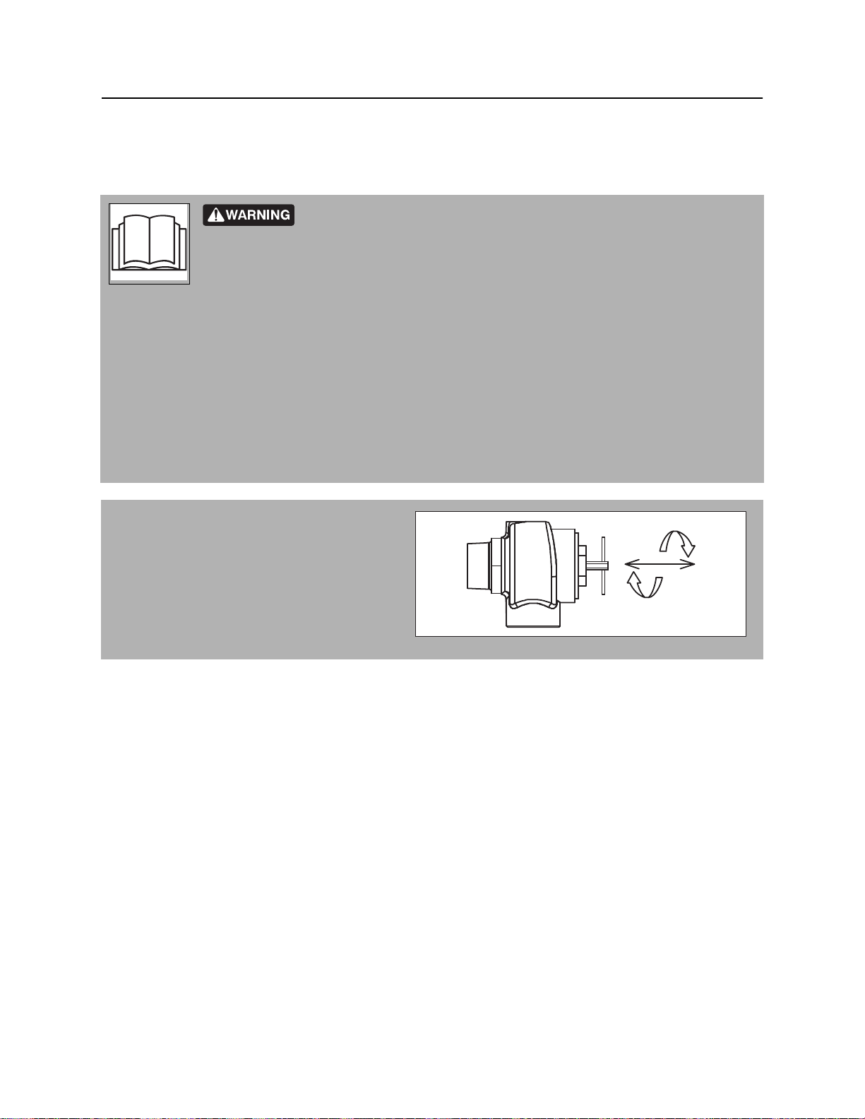
Vacuum Boom (optional)
Vacuum Boom (optional)
5
j35om053h.eps
1. Boom latch
2. Boom up
3. Boom down
Item Description Notes
1. Boom latch Pull cable to open latch and
3
4
2
4. Boom retract
5. Boom extend
release boom from saddle.
1
Push boom into latch to lock
boom into saddle.
CMW
Page 36

FX50 Operator’s Manual Controls - 35
Vacuum Boom (optional)
Item Description Notes
2. Boom up To raise boom, set hydraulic
function switch to the optional
boom position and press UP.
To stop movement, release.
3. Boom down To lower boom, set hydraulic
function switch to the optional
boom position and press UP.
To stop movement, release.
4. Boom retract To retract boom, set hydraulic
function switch to the optional
boom position and press IN.
To stop movement, release.
NOTICE: Do not use boom to raise or
lower objects.
NOTICE: Do not use boom to raise or
lower objects.
5. Boom extend To extend boom, set hydraulic
function switch to the optional
boom position and press
OUT.
To stop movement, release.
CMW
Page 37

Controls - 36 FX50 Operator’s Manual
Vacuum Boom (optional)
CMW
Page 38

FX50 Operator’s Manual Operation Overview - 37
Operation Overview
Chapter Contents
Planning . . . . . . . . . . . . . . . . . . . . . . . . . . . . . . . . . 38
Setting Up at Jobsite . . . . . . . . . . . . . . . . . . . . . . . 38
Vacuuming . . . . . . . . . . . . . . . . . . . . . . . . . . . . . . . 38
Potholing . . . . . . . . . . . . . . . . . . . . . . . . . . . . . . . . 39
Leaving Jobsite . . . . . . . . . . . . . . . . . . . . . . . . . . . 39
Storing Equipment . . . . . . . . . . . . . . . . . . . . . . . . . 39
CMW
Page 39

Operation Overview - 38 FX50 Operator’s Manual
Planning
Planning
1. Gather information about jobsite (page 42).
2. Inspect jobsite (page 43).
3. Check supplies and prepare equipment (page 45).
Setting Up at Jobsite
1. Prepare jobsite (page 44).
2. Position vacuum excavation unit.
3. Leave unit hitched to towing vehicle or properly stabilized.
4. Block trailer wheels.
Vacuuming
1. Connect hoses (page 52).
2. Start unit (page 56).
3. Position optional vacuum boom (page 58).
4. Remove debris (page 59).
5. Disconnect hoses (page 71).
6. Drain tank (page 62) or unload to another tank (page 64)
CMW
Page 40

FX50 Operator’s Manual Operation Overview - 39
Potholing
Potholing
1. Connect hoses (page 52).
2. Start unit (page 56).
3. Pothole (page 60).
4. Disconnect hoses (page 71).
5. Drain tank (page 62).
Leaving Jobsite
1. Rinse unit and tools (page 71).
2. Stow tools (page 72).
Storing Equipment
1. For cold weather storage, antifreeze vacuum excavation unit (page 70).
2. For long-term storage, disconnect battery disconnect switch (page 29).
CMW
Page 41

Operation Overview - 40 FX50 Operator’s Manual
Storing Equipment
CMW
Page 42

FX50 Operator’s Manual Prepare - 41
Prepare
Chapter Contents
Gather Information . . . . . . . . . . . . . . . . . . . . . . . . . 42
• Arrange for Traffic Control . . . . . . . . . . . . . . . . . . . . . . . . . . . . . . . . . . 42
• Prepare for Working Near Existing Utilities . . . . . . . . . . . . . . . . . . . . . 42
• Plan for Emergency Services . . . . . . . . . . . . . . . . . . . . . . . . . . . . . . . . 42
Inspect Jobsite . . . . . . . . . . . . . . . . . . . . . . . . . . . . 43
Prepare Jobsite . . . . . . . . . . . . . . . . . . . . . . . . . . . 44
• Prepare Excavation Point . . . . . . . . . . . . . . . . . . . . . . . . . . . . . . . . . . . 44
Check Supplies and Prepare Equipment . . . . . . . 45
• Assemble Accessories . . . . . . . . . . . . . . . . . . . . . . . . . . . . . . . . . . . . . 45
• Check Supplies . . . . . . . . . . . . . . . . . . . . . . . . . . . . . . . . . . . . . . . . . . 45
• Prepare Equipment . . . . . . . . . . . . . . . . . . . . . . . . . . . . . . . . . . . . . . . 46
CMW
Page 43

Prepare - 42 FX50 Operator’s Manual
Gather Information
Gather Information
A successful job begins before the excavation. The first step in planning is reviewing information already
available about the job and jobsite.
Arrange for Traffic Control
If working near a road or other traffic area, contact local authorities about safety procedures and
regulations.
Prepare for Working Near Existing Utilities
If jobsite may contain electrical lines, wear protective boots and gloves meeting the following standards:
• Boots must have high tops and meet the electric hazard protection requirements of ASTM F2413 or
ASTM F1117, when tested at 14,000 volts. Tuck legs of pants completely inside boots.
• Gloves must have 17,000 AC maximum use voltage, according to ASTM specification D120.
If working around higher voltage, use gloves and boots with appropriately higher ratings.
Plan for Emergency Services
Have the telephone numbers for local emergency and medical facilities on hand. Check that you will have
access to a telephone.
CMW
Page 44

FX50 Operator’s Manual Prepare - 43
Inspect Jobsite
Inspect Jobsite
• Follow U.S. Department of Labor regulations on excavating and trenching (Part 1926, Subpart P) and
other similar regulations.
• Contact your local One-Call (811 in USA) or the One-Call referral number (888-258-0808 in USA and
Canada) to have underground utilities located before digging. Also contact any utilities that do not
participate in the One-Call service..
• Inspect jobsite and perimeter for evidence of underground hazards, such as:
– “Buried utility” notices
– Utility facilities without overhead lines
– Gas or water meters
– Junction boxes
– Drop boxes
– Light poles
– Manhole covers
– Sunken ground
• Mark location of all buried utilities and obstructions.
CMW
Page 45

Prepare - 44 FX50 Operator’s Manual
Prepare Jobsite
Prepare Jobsite
Jobsite hazards could cause death or serious injury. Use
correct equipment and work methods. Use and maintain proper safety
equipment.
To help avoid injury:
• If jobsite classification is in question or if the possibility of unmarked electric utilities exists, classify
jobsite as electric.
• Expose lines by hand before digging. Cutting high voltage cable can cause electrocution.
• All vegetation near operator’s station must be removed. Contact with trees, shrubs, or weeds during
electrical strike could result in electrocution.
Prepare Excavation Point
• Clear the area to be excavated. Remove rocks or branches too large for vacuum hose.
• If excavating fluids while drill string is moving, clear area of trees, shrubs, and weeds.
• Select a solid area to stand on while excavating.
CMW
Page 46

FX50 Operator’s Manual Prepare - 45
Check Supplies and Prepare Equipment
Check Supplies and Prepare Equipment
Assemble Accessories
Fire Extinguisher
If required, mount a fire extinguisher near the power unit but away from possible points of ignition. The fire
extinguisher should always be classified for both oil and electric fires. It should meet legal and regulatory
requirements.
Lighting Kit
If you will need additional light, plug lighting kit into provided outlet. Contact your Ditch Witch dealer for
further information.
Check Supplies
• water and additional hoses
• fuel
• keys
• spray lubricant
• personal protective equipment, such as hard hat and safety glasses
CMW
Page 47

Prepare - 46 FX50 Operator’s Manual
Check Supplies and Prepare Equipment
Prepare Equipment
Fluid Levels
• fuel
• hydraulic fluid
• engine coolant
• battery charge
• engine oil
• blower oil
Condition and Function
• filters (air, oil, hydraulic)
• belts
• hydraulic pump
• blower
• tires
• hoses and valves
• couplers and fittings
• water tanks
CMW
Page 48

FX50 Operator’s Manual Transport - 47
Transport
Chapter Contents
Lift . . . . . . . . . . . . . . . . . . . . . . . . . . . . . . . . . . . . . . 48
• Points . . . . . . . . . . . . . . . . . . . . . . . . . . . . . . . . . . . . . . . . . . . . . . . . . . 48
• Procedure . . . . . . . . . . . . . . . . . . . . . . . . . . . . . . . . . . . . . . . . . . . . . . . 48
Haul . . . . . . . . . . . . . . . . . . . . . . . . . . . . . . . . . . . . . 49
• Inspect Trailer . . . . . . . . . . . . . . . . . . . . . . . . . . . . . . . . . . . . . . . . . . . 49
• Hitch Trailer . . . . . . . . . . . . . . . . . . . . . . . . . . . . . . . . . . . . . . . . . . . . . 50
• Unhitch Trailer . . . . . . . . . . . . . . . . . . . . . . . . . . . . . . . . . . . . . . . . . . . 50
CMW
Page 49

Transport - 48 FX50 Operator’s Manual
Lift
Lift
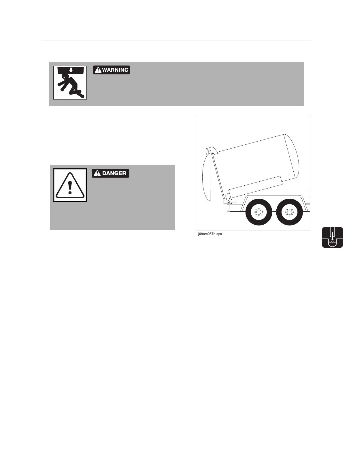
Crushing weight. If load falls or moves it could kill or crush you. Use
proper procedures and equipment or stay away.
Points
Lifting points are identified by lifting decals. Lifting at other points is unsafe
and can damage machinery.
Procedure
Power Pack
Use a crane capable of supporting 3000 lb (1360 kg).
Use top lift point as shown.
Tank
Use crane capable of supporting 2500 lb (1134 kg). Use
top lift point (1) as shown. Use end lift point (2) to drain
tank if machine is disabled.
NOTICE:
• Relieve pressure in tank before storing or
transporting.
• Only lift empty water or spoils tanks.
• Do not lift tank by vacuum boom, if installed.
CMW
Page 50

FX50 Operator’s Manual Transport - 49
Haul
Haul
Crushing weight. If load falls or moves it could kill or crush you. Use
proper procedures and equipment or stay away.
To help avoid injury:
• Do not haul or move trailer unless tank is fully lowered and horizontal. Damage to machine or injury
to personnel could occur.
• Do not haul or move trailer unless optional vacuum boom is secured by boom latch. Damage to
machine or injury to personnel could occur.
Inspect Trailer
• Check hitch for wear and cracks. Lubricate if needed.
• Check battery for 12 volt charge.
• Inspect lights for cleanliness and correct operation. Inspect reflectors and replace if needed.
• Check tire pressure. Check lug nut torque with a torque wrench.
• Ensure trailer brakes are adjusted to come on in synchronization with tow vehicle brakes.
• Check ramps (if equipped) and trailer bed for cracks.
CMW
Page 51

Transport - 50 FX50 Operator’s Manual
TrailerHitchAdjust_T18.eps
Haul
Hitch Trailer
1. Back tow vehicle to trailer.
2. Put manual transmission into first or reverse gear or automatic transmission into park. Turn off ignition.
Set parking brake.
3. Connect trailer drawbar, lunette or coupler to
tow vehicle hitch and lock in place with lock
pin. If needed, adjust drawbar, lunette or
coupler height (shown) to level load.
4. Connect safety chains to tow vehicle chain
keepers (cross-shaped slots on bumper of
tow vehicle). Attach left chain to right side of
tow vehicle and vice versa to cradle hitch. Do
not connect to pintle hook or hitch ball.
5. Connect breakaway switch cable to tow
vehicle. Do not connect to pintle hook or hitch
ball.
6. Plug trailer electrical connector into tow
vehicle connector.
7. Use jack crank to raise jack base and stow.
TrailerHitchAdjust_T18.eps
8. Remove wheel blocks.
Unhitch Trailer
1. Stop tow vehicle and trailer on level ground.
2. Put manual transmission into first or reverse gear or automatic transmission into park. Turn off ignition.
Set parking brake.
3. Block trailer wheels.
4. To unhitch trailer from tow vehicle, reverse “Hitch Trailer“ steps.
CMW
Page 52

FX50 Operator’s Manual Vacuum and Pothole - 51
Vacuum and Pothole
Chapter Contents
Connect Hoses . . . . . . . . . . . . . . . . . . . . . . . . . . . . 52
Determine Tank Fill Level . . . . . . . . . . . . . . . . . . . 53
• 300-gal Vacuum Tank on T9SE6 or T9SH6 Trailer . . . . . . . . . . . . . . . 53
• 800-gal Vacuum Tank on T18S Trailer . . . . . . . . . . . . . . . . . . . . . . . . 54
• 1200-gal Vacuum Tank on T26S Trailer . . . . . . . . . . . . . . . . . . . . . . . 55
Start Unit . . . . . . . . . . . . . . . . . . . . . . . . . . . . . . . . . 56
• Standard Procedure . . . . . . . . . . . . . . . . . . . . . . . . . . . . . . . . . . . . . . . 56
• Cold Start Procedure . . . . . . . . . . . . . . . . . . . . . . . . . . . . . . . . . . . . . . 57
Position Vacuum Boom . . . . . . . . . . . . . . . . . . . . . 58
Remove Debris . . . . . . . . . . . . . . . . . . . . . . . . . . . . 59
• Procedure . . . . . . . . . . . . . . . . . . . . . . . . . . . . . . . . . . . . . . . . . . . . . . . 59
Pothole . . . . . . . . . . . . . . . . . . . . . . . . . . . . . . . . . . 60
Drain Tank . . . . . . . . . . . . . . . . . . . . . . . . . . . . . . . 62
Unload to Another Tank . . . . . . . . . . . . . . . . . . . . 64
Open/Close Tank Door . . . . . . . . . . . . . . . . . . . . . 66
CMW
Page 53

Vacuum and Pothole - 52 FX50 Operator’s Manual
Connect Hoses
Connect Hoses
1. Remove vacuum hoses from storage.
2. If potholing, remove 2-in-1 potholing tool or basic potholing tool from storage.
3. Connect hoses. Secure all locking clamps.
4. Ensure drain/outlet valve is closed.
5. If potholing, connect water pressure hose.
2-in-1 Tool Basic Tool
CMW
Page 54

FX50 Operator’s Manual Vacuum and Pothole - 53
Determine Tank Fill Level
Determine Tank Fill Level
Use these reference charts to help determine how full of various materials the vacuum tank can be without
overloading trailer. Exceeding the maximum fill level will overload the trailer.
Never exceed the trailer capacity. You can exceed the vacuum tank lifting capacity if you drain the tank
down to the lifting capacity before lifting tank.
To use these charts, first select the appropriate table based on trailer and vacuum tank size. Next find the
material being excavated. If the material being excavated is not listed, find a material with similar density.
Then, determine the maximum fill level based on the amount of water in the water tank.
IMPORTANT: For all materials, the vacuum tank should be no more than half full when lifting the tank.
300-gal Vacuum Tank on T9S Trailer
Material Maximum Vacuum Tank
Fill Level
Water tank fill level full (80 gal) empty (0 gal)
wood chips (dry) 100% 100%
snow (dry) 100% 100%
water 76% 99%
light weight mud (8-10 lb/gal) 70% 92%
earth (dry, loose) 66% 86%
caliche 61% 79%
earth, loam 61% 79%
medium weight mud (10-12 lb/gal) 57% 75%
limestone (crushed) 49% 65%
asphalt 47% 62%
sand (dry) 47% 62%
earth (wet, excavated) 47% 62%
heavy weight mud (12-15 lb/gal) 47% 61%
gravel (dry) 46% 60%
shale, riprap 45% 59%
sand (wet) 36% 48%
CMW
Page 55

Vacuum and Pothole - 54 FX50 Operator’s Manual
Determine Tank Fill Level
800-gal Vacuum Tank on T18S Trailer
Material Maximum Vacuum Tank Fill Level
Water tank fill level full (200 gal) full (300 gal) empty (0 gal)
wood chips (dry) 100% 100% 100%
snow (dry) 100% 100% 100%
water 100% 93% 100%
light weight mud (8-10 lb/gal) 96% 86% 100%
earth (dry, loose) 90% 81% 100%
caliche 83% 74% 100%
earth, loam 83% 74% 100%
medium weight mud (10-12 lb/gal) 79% 70% 95%
limestone (crushed) 68% 61% 82%
asphalt 65% 58% 79%
sand (dry) 65% 58% 78%
earth (wet, excavated) 65% 58% 78%
heavy weight mud (12-15 lb/gal) 64% 57% 78%
gravel (dry) 63% 56% 76%
shale, riprap 62% 55% 75%
sand (wet) 50% 45% 61%
CMW
Page 56

FX50 Operator’s Manual Vacuum and Pothole - 55
Determine Tank Fill Level
1200-gal Vacuum Tank on BT26 Trailer
Material Maximum Vacuum Tank
Fill Level
Water tank fill level full (500 gal) empty (0 gal)
wood chips (dry) 100% 100%
snow (dry) 100% 100%
water 94% 100%
light weight mud (8-10 lb/gal) 87% 100%
earth (dry, loose) 82% 100%
caliche 75% 100%
earth, loam 75% 100%
medium weight mud (10-12 lb/gal) 71% 99%
limestone (crushed) 61% 85%
asphalt 59% 81%
sand (dry) 59% 81%
earth (wet, excavated) 59% 81%
heavy weight mud (12-15 lb/gal) 58% 81%
gravel (dry) 57% 79%
shale, riprap 56% 78%
sand (wet) 48% 63%
CMW
Page 57

Vacuum and Pothole - 56 FX50 Operator’s Manual
Start Unit
Start Unit
EMERGENCY SHUTDOWN: Turn ignition switch to STOP.
Standard Procedure
IMPORTANT: If power pack is not connected to external tank control
valves, connect a -04 hose with a minimum working pressure rating of
3000 psi (207 bar) from pressure (1) to power beyond (2) connections
on power pack.
j36om006w.eps
1. Open tank inlet valve.
NOTICE: Avoid idling engine with inlet valve closed.
2. If equipped with reverse flow, ensure vacuum is in “vacuum” mode before starting.
3. Insert key.
4. Turn key clockwise.See page 24 for more information.
NOTICE: If engine turns but does not start within 10 seconds, allow starter to cool before trying to
start engine again.
5. Run engine at low throttle for 5 minutes.
CMW
Page 58

FX50 Operator’s Manual Vacuum and Pothole - 57
Start Unit
Cold Start Procedure
Explosion possible. Serious injury or equipment damage could occur.
Follow directions carefully.
To help avoid injury: do not use ether or starting fluid.
1. Open tank inlet valve.
NOTICE: Avoid idling engine with inlet valve closed.
2. If equipped with reverse flow, ensure vacuum is in “vacuum” mode before starting.
3. Insert key.
4. Turn key clockwise to “run” position (key on, engine off). See page 24 for more information. Cold start
wait indicator will light.
5. Wait for cold start wait indicator to go off.
6. Turn key all the way clockwise to start engine.
NOTICE: If engine turns but does not start within 10 seconds, allow starter to cool before trying to
start engine again.
7. Run engine at low throttle for 5 minutes.
CMW
Page 59
Vacuum and Pothole - 58 FX50 Operator’s Manual
Position Vacuum Boom
Position Vacuum Boom
The vacuum boom is optional equipment. Contact your Ditch Witch dealer to add this option.
Procedure
Electric shock. Contacting electric lines will cause death or serious injury.
Know location of lines and stay away.
Incorrect procedures could result in death, injury, or property damage.
Learn to use equipment correctly.
To help avoid injury:
• Latch boom before tilting tank.
• Do not unlatch boom when tank is tilted up.
• If unit is parked on a slope, control boom so it does not swing freely when released.
• Do not use boom to lift or move objects. Using boom in an inappropriate way may damage
equipment or injure personnel.
See “Controls” on page 21 to become familiar with the power pack controls and the tethered boom
controller.
1. Start engine.
2. Set hydraulic function switch to “boom” position.
3. Remove vacuum hoses from storage.
4. Pull boom latch cable to release boom.
5. Use tethered boom controller to:
• raise boom until it clears saddle.
• extend/retract boom to desired length.
• raise/lower boom to desired height.
6. Rotate boom by manually swinging it left or right.
CMW
Page 60

FX50 Operator’s Manual Vacuum and Pothole - 59
Remove Debris
Remove Debris
EMERGENCY SHUTDOWN: Turn ignition switch to STOP.
Procedure
1. Position vacuum hose in area to be excavated.
2. Start engine.
Vacuum will suffocate. Maintain distance between face and
vacuum inlets.
Fire or explosion possible. Do not vacuum flammable or
combustible substances.
3. Open inlet valve if necessary to begin excavation.
Incorrect procedures could result in death, injury, or property
damage. Learn to use equipment correctly.
To help avoid injury: Do not excavate hazardous or toxic materials. Unit is designed to
excavate only soil cuttings, drilling fluids, and other non-toxic waste.
4. Use sight glasses to monitor debris level in tank. Vacuum will shut off when tank is full but always heed
trailer and tank lifting capacities as indicated on page 53. Engine will remain running.
CMW
Page 61

Vacuum and Pothole - 60 FX50 Operator’s Manual
Pothole
Pothole
EMERGENCY SHUTDOWN: Turn ignition switch to STOP.
1. Start engine.
Vacuum will suffocate. Maintain distance between face and
vacuum inlets.
Fire or explosion possible. Do not vacuum flammable or
combustible substances.
2. Open water tank valve.
3. Move water pump switch to on.
4. Open inlet valve if necessary.
5. Position tool over area to be excavated and begin pothole.
Electric shock. Contacting electric lines will cause death or
serious injury. Know location of lines and stay away.
To help avoid injury: Do not direct water lance at overhead lines. Water conducts electricity.
2-in-1 Tool Basic Tool
• Squeeze water pressure lever to start
water pressure.
• Work pressurized water in a rocking or
circular motion to loosen and excavate
soil until hole is at the desired diameter
and depth.
• First use water lance to loosen soil.
• Work tool in a rocking or circular motion to
excavate soil.
• Use water lance and tool alternately until
hole is at the desired diameter and depth.
CMW
Page 62

FX50 Operator’s Manual Vacuum and Pothole - 61
Pothole
6. Adjust water pressure as needed to match soil conditions and/or material of utility being exposed.
Jobsite hazards could cause death or serious injury. Use
correct equipment and work methods. Use and maintain proper safety
equipment.
To help avoid injury: Test water pressure on a sample of the material to be located. Adjust
pressure until no damage occurs to the material. High pressure water can cut utility lines.
7. Ensure that water sprays from nozzle in a fan pattern. If it does not, nozzle may be clogged and pump
will not function properly. Clean or replace nozzle as necessary.
8. When freshwater tank is empty, stop operation and turn water pump switch to off.
NOTICE: Do not continue to operate with freshwater tank empty. Running water pump with no
water will damage pump.
CMW
Page 63

Vacuum and Pothole - 62 FX50 Operator’s Manual
Drain Tank
Drain Tank
EMERGENCY SHUTDOWN: Turn ignition switch to STOP.
1. Ensure that unit is hitched to vehicle. See “Hitch Trailer” on page 50.
2. Haul unit to approved dumping area.
Incorrect procedures could result in death, injury, or property
damage. Learn to use equipment correctly.
To help avoid injury:
• Do not unhitch unit from tow vehicle before or during dumping. A freestanding unit can
become unstable when tilting tank.
• Do not unlatch door with tank tilted up.
• Do not unlatch vacuum boom (optional) with tank tilted up.
Breathing crystalline silica dust may cause lung disease. Cutting,
drilling, or working materials such as concrete, sand, or rock containing quartz may
result in exposure to silica dust. Use dust control methods or appropriate breathing
protection when exposed to silica dust.
NOTICE: Do not drive with tank or door raised.
3. Open drain/outlet valve and inlet valve.
4. Allow tank to drain in the horizontal position until
tank is approximately half drained. Monitor sight
glasses.
5. When tank is half drained, start engine and run at
low idle.
6. Tilt tank up to help flush solids from tank.
7. Lower tank to the full horizontal position.
8. Close drain/outlet valve and inlet valve.
CMW
Page 64
FX50 Operator’s Manual Vacuum and Pothole - 63
Drain Tank
9. If further draining is necessary, open tank door. See “Open/Close Tank Door” on page 66.
Crushing weight could cause death or serious injury. Use proper
procedures and equipment or stay away.
To help avoid injury: Use tools (provided with unit) if unit must be serviced with
tank door up.
10. Tilt tank up. Allow tank to drain completely.
11. Connect water pressure hose to water lance.
12. Turn water pump switch on. Adjust water pressure.
13. Use water lance to thoroughly rinse inside of tank
and around door seal.
Confined space
will cause suffocation. Use
proper procedures for entering
or stay away.
To help avoid injury: Enter tank only if
necessary. Follow U.S. Department of Labor
guidelines for entering confined spaces.
14. Return tank to the fully lowered horizontal position.
15. Close tank door. See “Open/Close Tank Door” on page 66.
CMW
Page 65
Vacuum and Pothole - 64 FX50 Operator’s Manual
Unload to Another Tank
Unload to Another Tank
Optional reverse flow mode can be used to transfer vacuumed material to another tank or disposal site.
Incorrect procedures could result in death, injury, or property damage.
Learn to use equipment correctly.
To help avoid injury:
• Keep unit in “vacuum” mode unless pressure is needed.
• Restrain hose prior to pressurization. Unrestrained hose may cause property damage, injury or
death.
• Do not open fitting cams or valves when tank is pressurized. Flying debris, plugs and doors can
cause injury or death.
• Do not open tank door while tank is pressurized.
• Do not use pressure to clear clogs in vacuum hose.
IMPORTANT: Check relief valves as shown
before each use.
j33om059h.eps
1. Throttle down completely and turn off engine. Securely connect transfer hose to FX tank. Ensure drain/
outlet valve on FX tank is closed.
2. Securely connect other end of transfer hose to offboard tank. Ensure inlet valve on offboard tank is
closed and tank is vented.
3. Open FX tank drain/outlet valve. Material will flow into transfer hose.
4. Open offboard tank inlet valve.
CMW
Page 66

FX50 Operator’s Manual Vacuum and Pothole - 65
Unload to Another Tank
5. Move valve handle counterclockwise to engage “reverse flow” mode and start engine. Material will flow
into offboard tank.
6. Increase throttle as desired to transfer material.
7. When transfer is complete, throttle down completely and turn off engine. Close FX tank drain/outlet
valve.
8. Close offboard tank inlet valve and disconnect hose from offboard tank inlet valve.
9. Move handle clockwise to “vacuum” mode and turn on engine.
10. Open FX tank drain/outlet valve. Material will empty from transfer hose.
11. Close FX tank drain/outlet valve, throttle down and turn off engine.
12. Disconnect transfer hose from FX tank.
CMW
Page 67

Vacuum and Pothole - 66 FX50 Operator’s Manual
Open/Close Tank Door
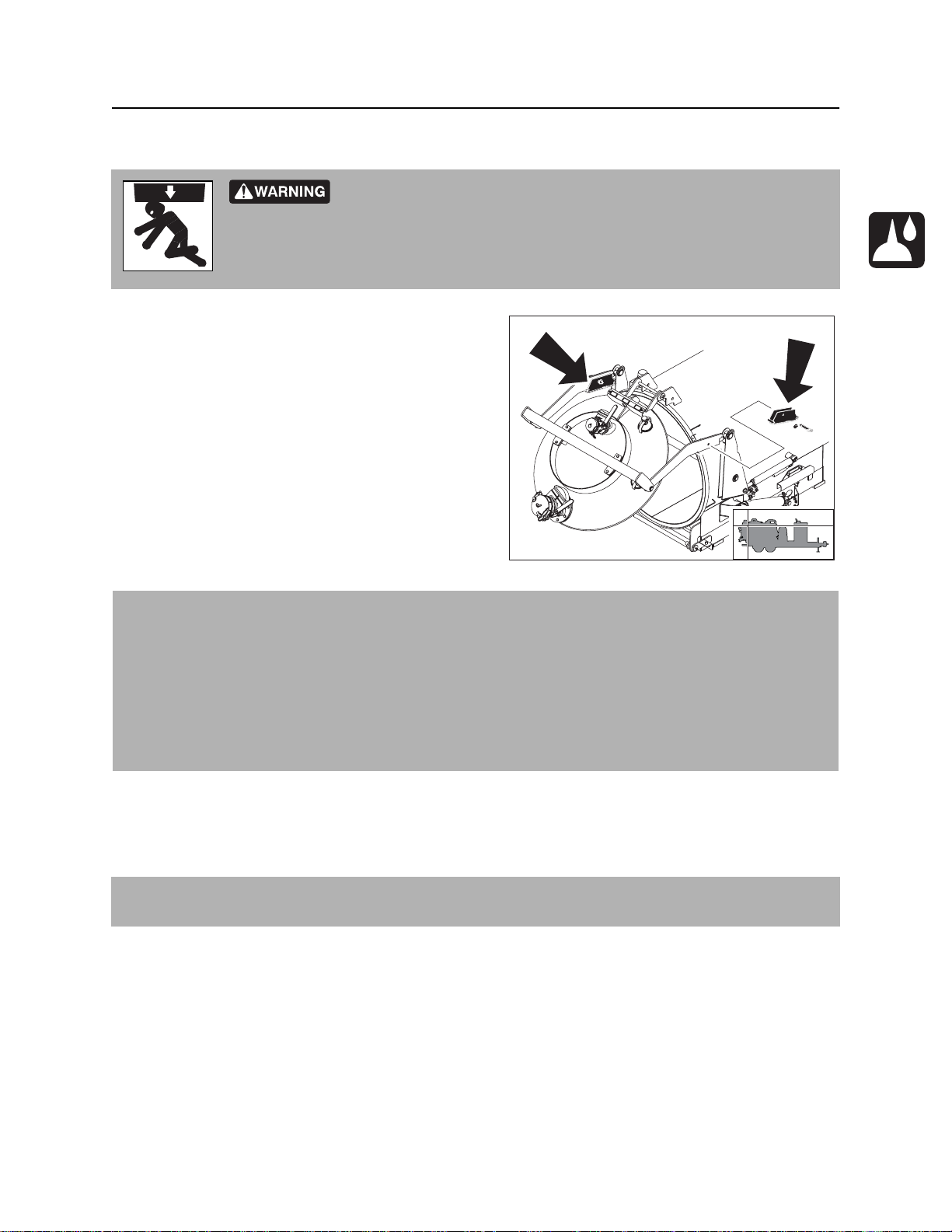
Open/Close Tank Door
Crushing weight could cause death or serious injury. Use proper
procedures and equipment or stay away.
To help avoid injury: Use tools (provided with unit) if unit must be serviced with tank
door up.
To help avoid injury: Do not raise tank with door held closed only by vacuum. Door may suddenly
open and possibly injure someone.
NOTICE: Do not drive with tank or door raised.
IMPORTANT: Depressurize tank before emptying cyclonic canister, cleaning filter, clearing hoses or
opening any doors.
300 or 800 Tank:
Open
1. If tank is tilted, lower tank fully before opening door.
2. Open tank inlet valve.
3. Set hydraulic function switch to door position.
4. Press OPEN on tethered control.
Close
1. Press CLOSE on tethered control until the linkage on both sides of the tank is fully collapsed.
2. Close tank inlet valve.
CMW
Page 68

FX50 Operator’s Manual Vacuum and Pothole - 67
Open/Close Tank Door
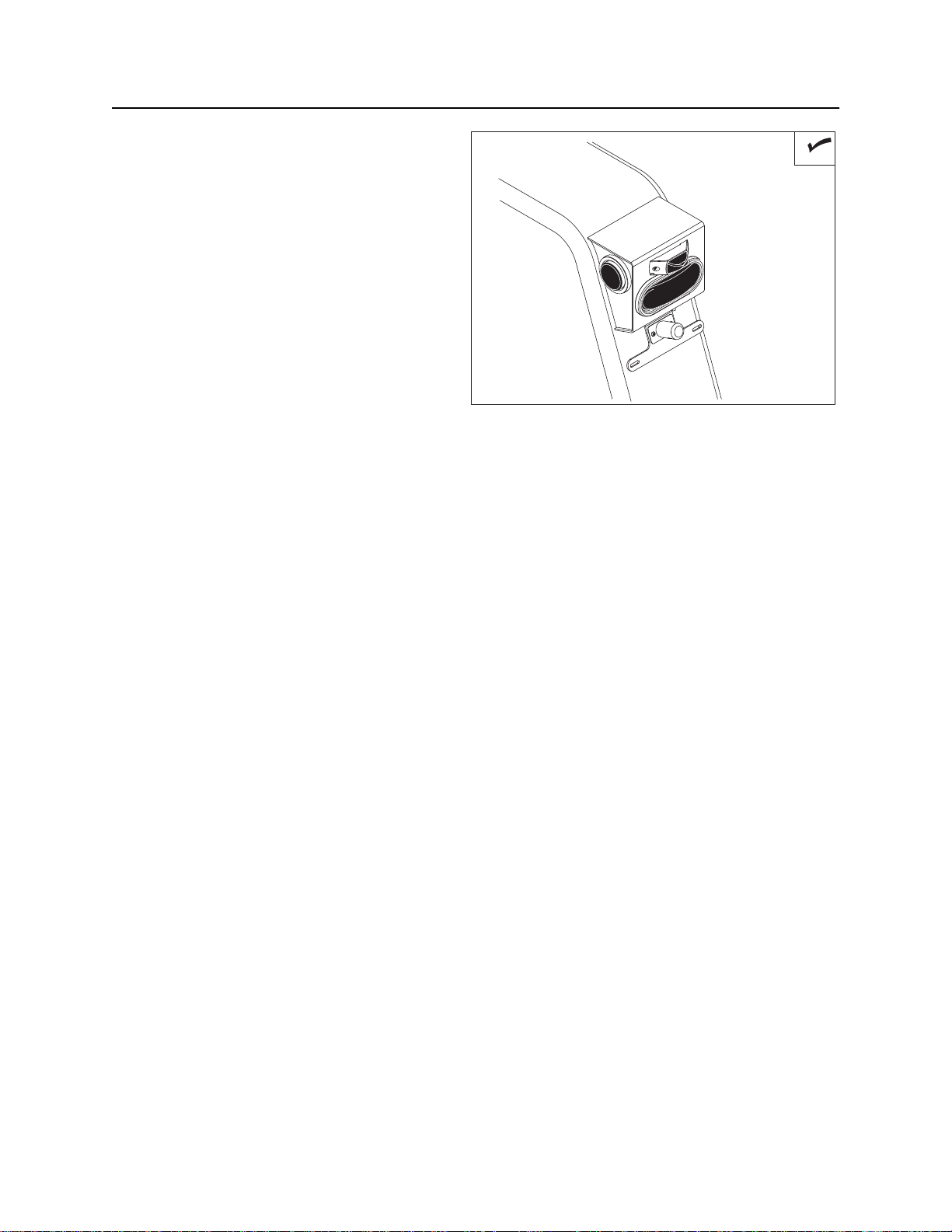
1200 Tank:
Open
1. Push door seal control to SEAL.
2. Turn tank door lock counterclockwise.
3. Pull door seal control to RELEASE.
4. Turn door handle to DISENGAGE and pull out.
5. Push door lift control to OPEN.
6. Ensure door lift latch (1) engages properly.
Door lift latch (1) should be fully seated on pin
(2).
NOTICE: If door latch is not fully seated on
pin, door will close and possibly injure
someone.
Close
1. Fully open door to disengage door lift latch (1)
from pin (2). Latch cover (3) must be down for
tank door to close.
2. Pull door lift control to CLOSE.
3. Turn door handle to DISENGAGE, push in and
turn to ENGAGE.
4. Push door seal control to SEAL.
om0663h.eps
1
2
1
2
3
5. Turn tank door lock clockwise until it stops to
lock.
6. Pull door seal control to RELEASE.
om0664h.eps
CMW
Page 69

Vacuum and Pothole - 68 FX50 Operator’s Manual
Open/Close Tank Door
CMW
Page 70

FX50 Operator’s Manual Complete the Job - 69
Complete the Job
Chapter Contents
Antifreeze Fluid Excavation Unit . . . . . . . . . . . . . 70
• Add Antifreeze . . . . . . . . . . . . . . . . . . . . . . . . . . . . . . . . . . . . . . . . . . . 70
• Reclaim Antifreeze . . . . . . . . . . . . . . . . . . . . . . . . . . . . . . . . . . . . . . . . 70
Rinse Equipment . . . . . . . . . . . . . . . . . . . . . . . . . . 71
Disconnect . . . . . . . . . . . . . . . . . . . . . . . . . . . . . . . 71
Stow Tools . . . . . . . . . . . . . . . . . . . . . . . . . . . . . . . 72
CMW
Page 71

Complete the Job - 70 FX50 Operator’s Manual
Antifreeze Fluid Excavation Unit
Antifreeze Fluid Excavation Unit
Add Antifreeze
Follow these steps for overnight or long-term storage of unit during cold weather.
1. Fill antifreeze tank with a propylene-glycol based antifreeze.
2. Ensure that water tank valve is closed.
3. Open antifreeze tank valve.
4. Connect water pressure hose to water lance.
5. Start engine.
6. Move water pump switch to on. If freshwater tank is empty, move to bypass.
7. Squeeze water lance handle and run until antifreeze runs through the water lance.
8. Move water pump switch to off.
9. Close antifreeze tank supply valve.
10. Turn ignition switch to off.
11. Drain water tank completely.
Reclaim Antifreeze
1. Turn water pressure down.
2. Move water pump switch to on.
3. Put end of water lance in antifreeze tank.
4. Squeeze water lance handle and run until water comes out of lance.
5. Move water pump switch to off.
CMW
Page 72

FX50 Operator’s Manual Complete the Job - 71
Rinse Equipment
Rinse Equipment
Spray water onto equipment to remove dirt and mud. Use water lance. Thoroughly rinse inside of tank and
around door seal.
Confined space will cause suffocation. Use proper procedures for
entering or stay away.
To help avoid injury: Enter tank only if necessary. Follow U.S. Department of Labor guidelines for
entering confined spaces.
NOTICE: Do not spray water onto operator’s console. Electrical components could be damaged. Wipe
down instead.
Disconnect
Disconnect and store the following hoses and cables (if used):
• vacuum hoses
• water pressure hose
CMW
Page 73

Complete the Job - 72 FX50 Operator’s Manual
Stow Tools
Stow Tools
Make sure optional vacuum boom, potholing tools, water lance, and other tools are properly stowed.
CMW
Page 74

FX50 Operator’s Manual Service - 73
Service
Chapter Contents
Precautions . . . . . . . . . . . . . . . . . . . . . . . . . . . . . . 74
Recommended Lubricants/Service Key . . . . . . . 76
Each Use . . . . . . . . . . . . . . . . . . . . . . . . . . . . . . . . . 78
10 Hour . . . . . . . . . . . . . . . . . . . . . . . . . . . . . . . . . . 81
25 Hour . . . . . . . . . . . . . . . . . . . . . . . . . . . . . . . . . . 90
50 Hour . . . . . . . . . . . . . . . . . . . . . . . . . . . . . . . . . . 91
100 Hour . . . . . . . . . . . . . . . . . . . . . . . . . . . . . . . . . 95
250 Hour . . . . . . . . . . . . . . . . . . . . . . . . . . . . . . . . . 96
500 Hour . . . . . . . . . . . . . . . . . . . . . . . . . . . . . . . . . 97
1000 Hour . . . . . . . . . . . . . . . . . . . . . . . . . . . . . . . . 98
2000 Hour . . . . . . . . . . . . . . . . . . . . . . . . . . . . . . . . 99
As Needed . . . . . . . . . . . . . . . . . . . . . . . . . . . . . . 101
200 Mile . . . . . . . . . . . . . . . . . . . . . . . . . . . . . . . . . 108
3000 Mile . . . . . . . . . . . . . . . . . . . . . . . . . . . . . . . . 110
12,000 Mile . . . . . . . . . . . . . . . . . . . . . . . . . . . . . . 112
CMW
Page 75

Service - 74 FX50 Operator’s Manual
FX_Tank_Raised.eps
Precautions
Precautions
Incorrect procedures could result in death, injury, or property damage.
Learn to use equipment correctly.
To help avoid injury:
• Unless otherwise instructed, all service should be performed with engine off.
• Refer to engine manufacturer’s manual for engine maintenance instructions.
Working Under Raised Debris Tank
Crushing weight could cause death or serious injury. Use proper
procedures and equipment or stay away.
To help avoid injury: Use tools (provided with unit) if hydraulic system must be serviced
with tank tilted up.
1. Raise vacuum tank.
2. Remove cylinder lockout tool and place over
extended cylinder rod.
3. Lower vacuum tank until load is supported by
cylinder lockout tool.
FX_Tank_Raised.eps
CMW
Page 76
FX50 Operator’s Manual Service - 75
Precautions
Working Under Raised Tank Door
Crushing weight could cause death or serious injury. Use proper
procedures and equipment or stay away.
To help avoid injury: Use tools (provided with unit) if unit must be serviced with tank
door up.
1. Locate door lock tools in tool storage area and bring
to rear of tank.
2. Raise tank door completely.
3. Pin door lock tools into place as shown.
4. Lower tank lid until load is supported by door lock
tools.
Welding Precaution
NOTICE: Welding can damage electronics.
• Disconnect battery to prevent damage to battery. Do not turn off battery disconnect switch with
engine running, or alternator and other electronic devices may be damaged.
• Connect welder ground clamp close to welding point and make sure no electronic components are
in the ground path.
• Always disconnect the Engine Control Unit ground connection from the frame, harness connections
to the ECU, and other electronic components prior to welding on machine or attachments.
j36om019w.eps
Washing Precaution
NOTICE: Water can damage electronics. When cleaning equipment, do not spray electrical components
with water.
CMW
Page 77

Service - 76 FX50 Operator’s Manual
Recommended Lubricants/Service Key
Recommended Lubricants/Service Key
Item Description
DEO Diesel engine oil meeting or exceeding CH-4 per the API service classification or E5
per the European Automobile Manufacturer’s Association (ACEA) and SAE viscosity
recommended by engine manufacturer (SAE 15W40)
HTG NGLI #2 premium grade, petroleum-based grease with high temperature resistance
and good mechanical stability
NDO SAE30 non-detergent oil
SGL Synthetic gear oil, ISO 100, p/n 256-044. See blower manual for more information.
MPL Multipurpose gear oil meeting API service classification GL-5 (SAE 80W90)
THF Tractor hydraulic fluid, similar to Phillips 66 HG, Mobilfluid 423, Chevron Tractor
Hydraulic Fluid, Texaco TDH Oil, or equivalent
MPG Multipurpose grease meeting ASTM D217 and NLGI 5
DOT DOT 3 or 4 brake fluid
Check level of fluid or lubricant
Check condition
Filter
Change, replace, adjust, service or test
Proper lubrication and maintenance protects Ditch Witch equipment from damage and failure. Service
intervals listed are for minimum requirements. Use only recommended lubricants. Fill to capacities listed in
“Specifications” on page 115.
For more information on engine lubrication and maintenance, see your engine manual.
NOTICE:
• Use only genuine Ditch Witch parts, filters, approved lubricants, TJC, and approved coolants to
maintain warranty.
• Use the “Service Record” on page 131 to record all required service to your machine.
CMW
Page 78

FX50 Operator’s Manual Service - 77
Recommended Lubricants/Service Key
Engine Oil Temperature Chart
Temperature range anticipated before next oil change
See engine manual for more information about oil viscosity and operation in arctic conditions.
Approved Fuel
This engine is designed to run on diesel fuel. Use only high quality fuel meeting ASTM D975 No. 2D,
EN590, or equivalent. At temperatures below 32° F (0° C) winter fuel blends are acceptable. See the
engine operation manual for more information.
IMPORTANT: Fuel sulfur content should be less than 5000 ppm (0.5%). Worldwide, fuel sulfur
regulations vary widely. Fuel used should always comply with local regulations. If using lube oil meeting
API CJ-4, (or other low SAPS equivalent) and fuel with sulfur content above 15 ppm (0.0015%), ULSD
in the U.S.), reduce oil change interval to 250 hours.
Biodiesel blends up to 5% (B5) are approved for use in this unit. The fuel used must meet the
specifications for diesel fuel shown above. In certain markets, higher blends may be used if certain steps
are taken. Extra attention is needed when using biodiesel, especially when operating in cold weather or
storing fuel. Contact your Ditch Witch dealer or the engine manufacturer for more information.
CMW
Page 79

Service - 78 FX50 Operator’s Manual
Each Use
Each Use
Location Task Notes
Trailer Check torque of hitch bolts
Check hydraulic brake actuator bolts If equipped
Check hydraulic brake fluid level If equipped; DOT 3 or 4
Check trailer battery
Check tire pressure and lug nut torque
Check lights and reflectors
Trailer
Check Torque of Hitch Bolts
Check torque of hitch bolts. Torque varies by
trailer model. Refer to “Specifications” on
page 115.
Check Hydraulic Brake Actuator Bolts
Check hydraulic brake actuator bolts. Tighten if
loose.
j36om020w.eps
CMW
j36om021w.eps
Page 80

FX50 Operator’s Manual Service - 79
Each Use
Check Hydraulic Brake Fluid Level
Check hydraulic brake fluid level at master
cylinder each use. Fluid should be visible a top of
master cylinder. Add DOT 3 or DOT 4 brake fluid
and bleed brakes as needed. See page 107.
j36om022w.eps
Check Trailer Battery
Check battery connections for wear or corrosion.
Keep connections clean and tight. Batteries
supplied by factory are maintenance-free. Service
replacement batteries according to
manufacturer’s instructions.
Check Tire Pressure and Lug Nut
Torque
Check tire pressure (2) and lug nut (1) torque.
See below for correct pressure and torque.
Trailer Pressure Torque
T9S 80 psi (5.5 bar) 95 ft•lb (129 N•m)
T18S 125 psi (8.6 bar) 300 ft•lb (407 N•m)
T26S 110 psi (7.6 bar) 271 ft•lb (271 N•m)
j36om023w.eps
1
2
j36om051w.eps
CMW
Page 81
Service - 80 FX50 Operator’s Manual
j33om013h.eps
Each Use
Check Lights and Reflectors
Check lights and reflectors for correct operation
and cleanliness.
j33om013h.eps
CMW
Page 82

FX50 Operator’s Manual Service - 81
10 Hour
10 Hour
Location Task Notes
Vacuum
System
Debris Tank Check vacuum tank hoses
Check engine oil level
Inspect belts (water pump, blower and fan)
Check air filter service indicator
Check hydraulic fluid level THF
Check hydraulic hoses
Check blower oil level SGL
Check blower
Check water pump oil level NDO
Check water pump
Check water pump regulator
Clean water pump filter
Clean vacuum air filter
Check spray nozzle
Drain cyclonic separator canister
Check strobe light
Check vacuum tank door seals/fittings
Check tank deflector
CMW
Page 83

Service - 82 FX50 Operator’s Manual
10 Hour
Vacuum System
Check Engine Oil Level
Check engine oil at dipstick (2) before operation
and every 10 hours thereafter. Check with unit on
level surface and at least 15 minutes after
stopping engine. Add DEO at fill (1) as necessary
to keep oil level at highest line on dipstick.
Inspect Belts
Check fan (2), blower (1), and water pump (3)
belts every 10 hours for damage or wear.
1
2
j36om009w.eps
1
2
CMW
3
j36om058w.eps
Page 84

FX50 Operator’s Manual Service - 83
10 Hour
Check Air Filter Indicator and Clean
Dust Trap
Check air filter indicator (2) and inspect dust trap
(1) for cracks every 10 hours. Change filter
elements when indicator reaches red zone.
NOTICE: Only open the air filter canister when
air restriction is indicated. Change the elements,
do not attempt to clean them.
• Compressed air or water may damage filter
elements.
12
• Tapping filter elements to loosen dirt may
damage filter seals.
Check Hydraulic Fluid Level
With frame level, check oil at indicator every 10
hours. Add THF at fill (1) as necessary. Clean dust
from cap by blowing with low-pressure air.
j36om007w.eps
1
j36om010w.eps
CMW
Page 85

Service - 84 FX50 Operator’s Manual
10 Hour
Check Hydraulic Hoses
Check hoses every 10 hours for wear or damage.
Replace as needed.
Fluid or air pressure could pierce skin and cause injury or
death. Stay away.
To help avoid injury:
• Before disconnecting a hydraulic line, turn engine off and operate all controls to relieve pressure.
Lower, block, or support any raised component with a hoist. Cover connection with heavy cloth and
loosen connector nut slightly to relieve residual pressure. Catch all fluid in a container.
• Before using system, check that all connections are tight and all lines are undamaged.
• Fluid leaks can be hard to detect. Use a piece of cardboard or wood, rather than hands, to search
for leaks.
• Wear protective clothing, including gloves and eye protection.
• If you are injured, seek immediate medical attention from a doctor familiar with this type of injury.
CMW
Page 86

FX50 Operator’s Manual Service - 85
10 Hour
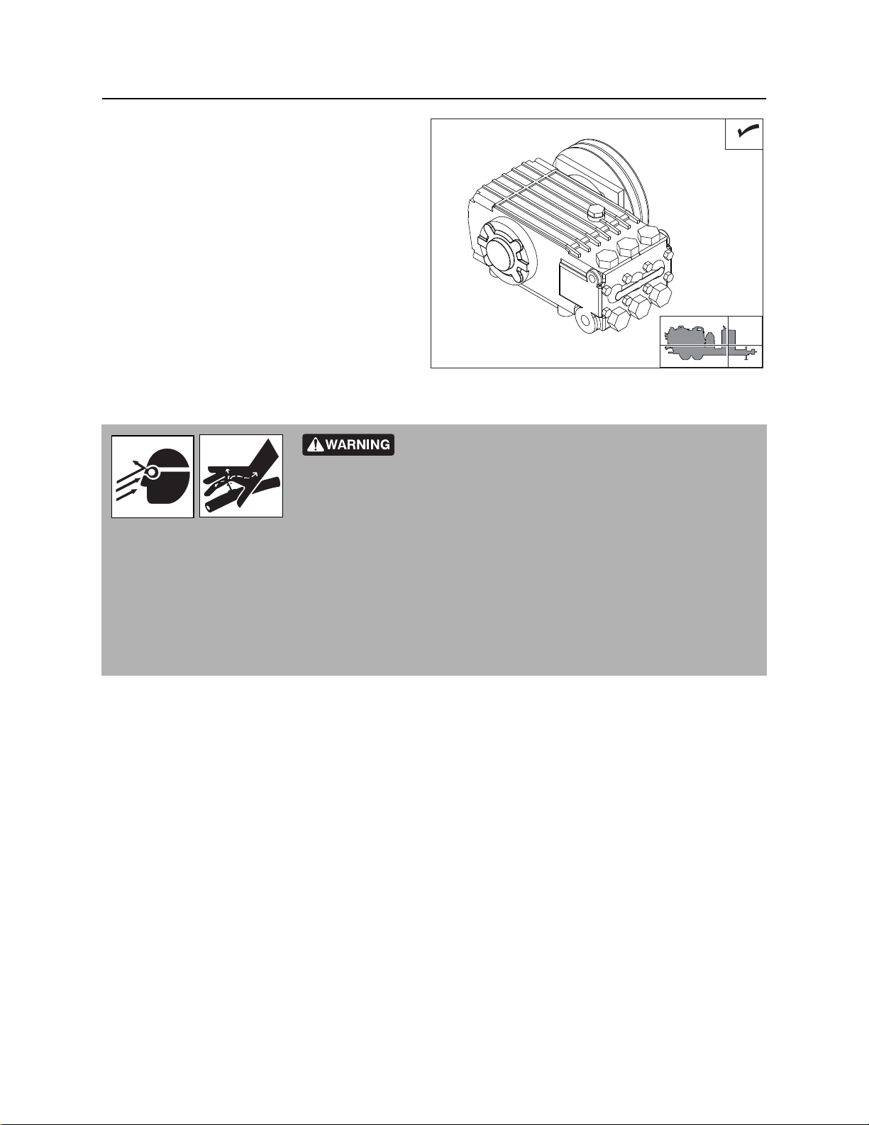
Check Blower Oil Level
1
With frame level, check blower oil at sight glass
(2) every 10 hours. Add SGL at breather (1) as
necessary to maintain oil level at halfway point on
sight glass (2). Do not overfill.
2
j36om011w.eps
Check Blower
Check blower every 10 hours for unusual noise or
vibration. If malfunction is detected:
1. Stop engine.
2. Consult blower repair manual.
Check Water Pump Oil Level
With frame level, check water pump oil at dipstick
every 10 hours. Oil should be [where?] on sight
glass (2). Add NDO at fill (1) as necessary to keep
oil at full mark on dipstick.
j36om024w.eps
1
2
j36om013w.eps
CMW
Page 87
Service - 86 FX50 Operator’s Manual
10 Hour
Check Water Pump
Check water pump unit every 10 hours for leaks,
loose fittings, unusual noise or vibration. Repair if
necessary.
j36om025w.eps
Fluid or air pressure could pierce skin and cause injury or
death. Stay away.
To help avoid injury:
• Before using system, check that all connections are tight and all lines are undamaged.
• Use a piece of cardboard or wood, rather than hands, to search for leaks. Fluid leaks can be hard to
detect.
• Wear protective clothing, including gloves and eye protection.
CMW
Page 88

FX50 Operator’s Manual Service - 87
10 Hour
Check Water Pump Regulator
Check for proper operation of regulator every 10
hours.
To check:
1. Start engine.
2. Connect water pressure hose to water lance.
3. Move water pressure switch to on.
4. Squeeze water lance handle. Water pump
should engage.
5. Release water lance handle. Water pump
should disengage.
If pump does not engage and disengage with movement of water lance handle, water pump control system
is not functioning properly. See water pump manual for more information.
j36om062w.eps
Clean Water Pump Filter
Clean water pump filter every 10 hours and
replace as needed.
1. Open filter housing.
2. Remove element and rinse housing
thoroughly with water.
3. Inspect element for signs of collapse and for
brittle or broken rubber seals on the ends of
the element. Replace as needed. See
page 103.
4. Replace element and close filter housing.
j36om026w.eps
CMW
Page 89

Service - 88 FX50 Operator’s Manual
10 Hour
Clean Vacuum Air Filter
Clean filter every 10 hours or as needed.
To clean filter:
1. Remove filter from canister.
2. Run low pressure water into inside of filter.
NOTICE: Do not use high pressure water
to clean filter. Filter will be damaged.
3. Allow filter to dry completely before returning
to canister.
j36om027w.eps
Check Spray Nozzle
Check spray nozzle every 10 hours. Ensure that
water sprays from nozzle in a fan pattern. Clean
or replace nozzle as necessary.
Drain Cyclonic Separator Canister
IMPORTANT: Depressurize tank before
emptying cyclonic canister, cleaning filter,
clearing hoses or opening any doors.
Drain canister at drain (2) every 10 hours or when
water is visible in sight glass (1).
CMW
j36om029w.eps
1
2
j36om028w.eps
Page 90

FX50 Operator’s Manual Service - 89
10 Hour
Debris Tank
Check Vacuum Tank Hoses
Check hoses every 10 hours for wear or damage.
Replace as needed.
j36om034w.eps
Check Strobe Light
Check strobe light for proper function every 10
hours. When ignition is on, strobe light should be
flashing. Repair if necessary.
Check Vacuum Tank Door Seals and
Fittings
Check door seal every 10 hours for wear or
damage. Repair if necessary. Check for leaks and
loose fittings every 10 hours. Repair or replace if
necessary.
j36om035w.eps
j36om036w.eps
CMW
Page 91

Service - 90 FX50 Operator’s Manual
25 Hour
Check Tank Deflector
Check tank deflector every 10 hours for buildup,
wear, or damage. Clean or replace as needed.
j36om037w.eps
25 Hour
Location Task Notes
Vacuum
System
Change water pump oil Initial service, NDO
Vacuum System
Change Water Pump Oil
Change oil after the first 25 hours of operation and
every 100 hours thereafter. Change oil more
frequently if working in dusty conditions.
• Drain at drain plug (3) while oil is warm.
• Add NDO at fill (1) until oil is at halfway mark
on sight glass (2).
1
3
2
j36om015w.eps
CMW
Page 92
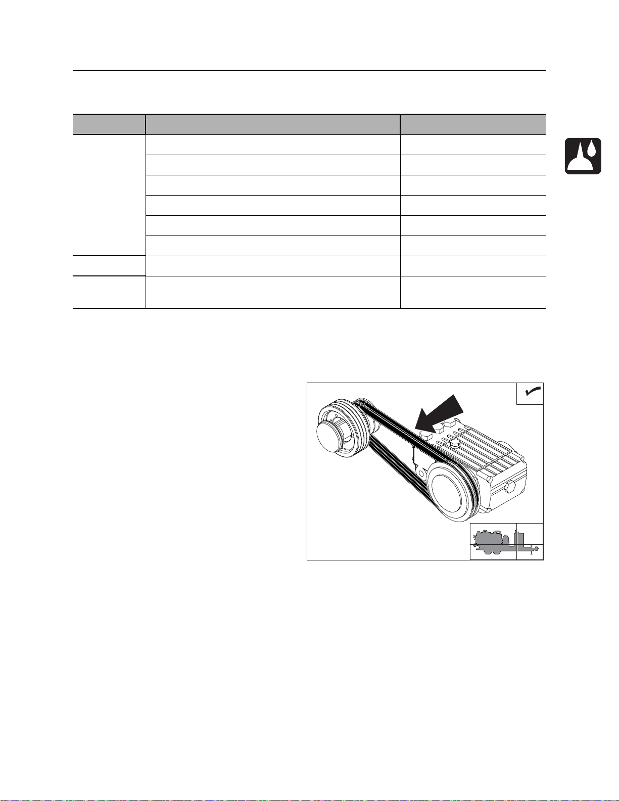
FX50 Operator’s Manual Service - 91
50 Hour
50 Hour
Location Task Notes
Vacuum
System
Debris Tank Lube tank pivot pins
Vacuum
Boom
Check water pump belt tension
Check fan belt tension
Check blower belt tension
Inspect cooling fan
Check blower relief valve
Check water pressure hoses
Lube boom pivot Boom is optional equipment
Vacuum System
Check Water Pump Belt Tension
Check belt every 10 hours for correct tension,
damage or wear. Replace worn belt. Tighten as
needed. See “Adjust Water Pump Belt Tension”
on page 103.
To check
1. Turn ignition to STOP and remove key.
2. Apply moderate thumb pressure to belt
between pulleys.
Belt is properly tensioned when deflection is
about .2-.3” (5-8 mm).
j36om014w.eps
CMW
Page 93

Service - 92 FX50 Operator’s Manual
50 Hour
Check Fan Belt Tension
Check fan belt tension every 50 hours. Belt is
properly tensioned when it moves about 3/8” (10
mm) when pushed at the long span (shown).
Adjust as needed. See “Adjust Fan Belt Tension”
on page 102.
j36om073w.eps
Check Blower Belt Tension
Check belt every 10 hours for correct tension,
damage or wear. Replace worn belt. Both ends of
tube must touch spring caps for belt to be
correctly tensioned. Tighten as needed. See
“Adjust Blower Belt Tension” on page 103.
Inspect Cooling Fan
Check for cracks, loose rivets, and bent or loose
blades. Check mounting screws and tighten if
needed.
j36om012w.eps
j36om060w.eps
CMW
Page 94

FX50 Operator’s Manual Service - 93
50 Hour
Check Blower Relief Valve
Check relief valve for proper operation every 50
hours.
To check:
1. Ensure that vacuum inlet valve and drain
valve are both closed.
2. Start engine. Vacuum will start to build.
3. When vacuum goes over relief, check for
suction at the bottom of the relief air filter.
If suction is not present, stop engine and
check relief valve.
Check Water Pressure Hoses
Check hoses every 50 hours for wear or damage.
Replace as needed.
j36om068w.eps
j36om030w.eps
CMW
Page 95

Service - 94 FX50 Operator’s Manual
50 Hour
Debris Tank
Lube Tank Pivot Pins
Lube two pins every 50 hours with MPG.
j36om032w.eps
Vacuum Boom
Lube Boom Pivot
Lube six zerks every 50 hours with MPG.
j36om033w.eps
CMW
Page 96

FX50 Operator’s Manual Service - 95
100 Hour
100 Hour
Location Task Notes
Vacuum
System
Debris Tank Check tank mounting bolts
Vacuum
Boom
Change water pump oil NDO
Lube blower bearings HTG
Check structure
Vacuum System
Change Water Pump Oil
Change oil after the first 25 hours of operation and
every 100 hours thereafter. Change oil more
frequently if working in dusty conditions.
• Drain at drain plug (3) while oil is warm.
• Add NDO at fill (1) until oil is at halfway mark
on sight glass (2).
1
3
Lube Blower Bearings
Wipe two zerks (1) clean and lube every 100
hours with HTG. Inject grease into zerk until clean
grease comes out of relief fittings (2).
NOTICE: Do not inject grease too quickly. Drive
shaft seal damage could occur.
2
j36om015w.eps
1
2
j36om070w.eps
CMW
Page 97

Service - 96 FX50 Operator’s Manual
250 Hour
Debris Tank
Check Tank Mounting Bolts
Check vacuum tank mounting bolts (shown, on
both sides) every 100 hours for looseness and
damage. Tighten or replace as needed.
Vacuum Boom
j36om038w.eps
Check Structure
Check boom elbow every 100 hours. Replace as needed.
250 Hour
Location Task Notes
Vacuum
System
Vacuum System
Inspect Air Intake System
Inspect intake piping for cracked hoses, loose
clamps, or punctures. Tighten or replace parts as
necessary.
Inspect air intake system
CMW
j36om040w.eps
Page 98

FX50 Operator’s Manual Service - 97
500 Hour
500 Hour
Location Task Notes
Vacuum
System
Change engine oil and filter DEO
Change fuel filter and clean filter screen
Vacuum System
Change Engine Oil and Filter
Change oil and filter every 500 hours.
1. Drain crankcase through drain (1) while oil is
warm.
2. Replace filter (2) each time oil is changed.
3. Add 8 qt (7.5L) of DEO at fill neck (4).
4. Verify correct oil level at dipstick (3).
1
j36om041w.eps
2
3
4
Change Fuel Filter
Replace fuel filter (4) and clean filter screen every
500 hours for normal service. See parts manual or
contact your Ditch Witch dealer for correct
replacement filter.
To clean filter screen:
1. Close fuel shut-off valve.
2. Unscrew nut (1).
3. Remove fuel strainer cover (2).
4. Clean fuel strainer (2) with diesel fuel.
Replace if necessary.
5. Place seal (3) in position.
6. Mount fuel strainer cover (2). Tighten screw (1).
7. Check for leaks.
4
1
23
j36om042w.eps
CMW
Page 99

Service - 98 FX50 Operator’s Manual
1000 Hour
1000 Hour
Location Task Notes
Vacuum
System
Change blower oil SGL
Change hydraulic fluid THF
Vacuum System
Change Blower Oil
Change oil every 1000 hours. Change oil more
frequently if working in dusty conditions.
• Drain at drain plug (3) while oil is warm.
• Add SGL at breather (1) until oil is at halfway
point on sight glass (2).
1
2
3
j36om064w.eps
Change Hydraulic Fluid
Drain hydraulic fluid (2) and add (1) THF every
1000 hours. Change fluid every 500 hours if
jobsite temperature exceeds 100°F (38°C) more
than 50% of the time.
1
2
j36om065w.eps
CMW
Page 100

FX50 Operator’s Manual Service - 99
2000 Hour
2000 Hour
Location Task Notes
Vacuum
System
Replace water pump belt
Replace blower belt
Replace fan belt
Vacuum System
Replace Water Pump Belt
Replace belt every 2000 hours.
Replace Blower Belt
Replace belt every 2000 hours.
j36om043w.eps
j36om044w.eps
CMW
 Loading...