


FX20
Operator’s
Manual
CMW
®
Issue 1.1
053-1270

FX20 Operator’s Manual Overview - 1
Overview
Chapter Contents
Serial Number Location . . . . . . . . . . . . . . . . . . . . . . 2
Intended Use . . . . . . . . . . . . . . . . . . . . . . . . . . . . . . . 2
Unit Components . . . . . . . . . . . . . . . . . . . . . . . . . . . 3
Operator Orientation. . . . . . . . . . . . . . . . . . . . . . . . . 4
About This Manual . . . . . . . . . . . . . . . . . . . . . . . . . . 4
• Bulleted Lists. . . . . . . . . . . . . . . . . . . . . . . . . . . . . . . . . . . . . . . . . . . . . . .4
• Numbered Lists. . . . . . . . . . . . . . . . . . . . . . . . . . . . . . . . . . . . . . . . . . . . .4
CMW
Overview - 2 FX20 Operator’s Manual
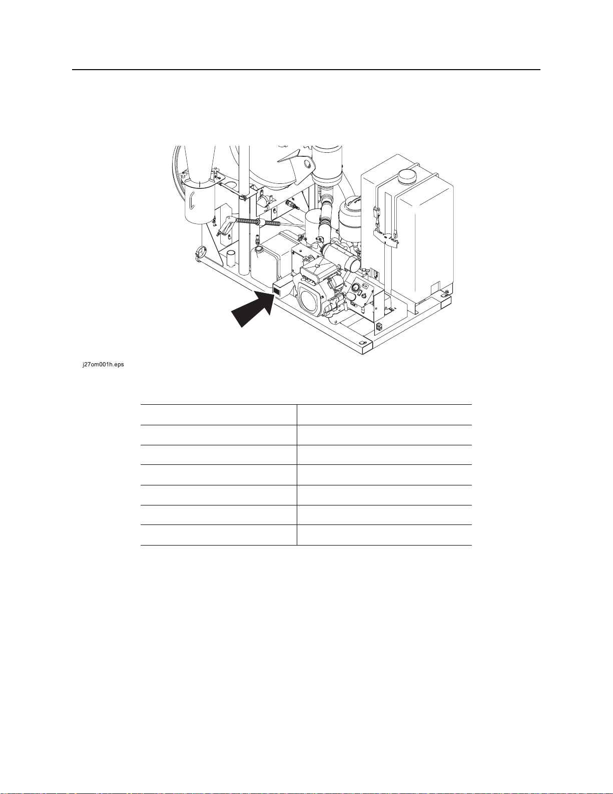
Serial Number Location
Serial Number Location
Record serial numbers and date of purchase in spaces provided. FX20 serial number is located as shown.
Date of manufacture
Date of purchase
FX20 serial number (shown)
Engine serial number
Blower serial number
Water pump serial number
Trailer serial number
Intended Use
The FX20 is a self-contained vacuum excavation unit capable of vacuuming a wide variety of nonhazardous, non-flammable liquid and solid debris. It is designe d to perform efficient soft excavation,
including exposing utilities for visual verification and/or potholing, and is intended for operation in ambient
temperatures from 0° to 115°F (-18° to 46°C). Use in any other way is considered contrary to the intended
use.
The FX20 should be operated, serviced, and repaired only by persons familiar with its particular
characteristics and acquainted with the relevant safety procedures.
CMW
FX20 Operator’s Manual Overview - 3
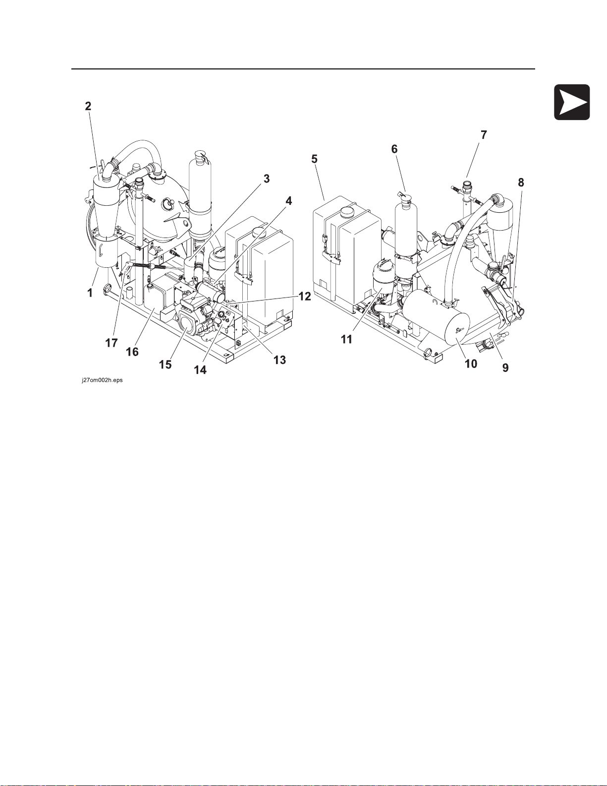
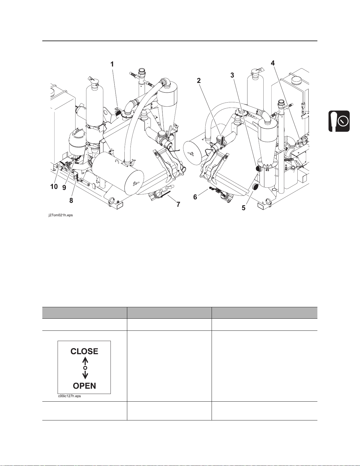
Unit Components
Unit Components
1. Cyclonic filter reservoir
2. Cyclonic filter
3. Air pre-filter
4. Blower
5. Water tank
6. Blower silencer
7. Potholing tools
8. Door prop
9. Vacuum tank
10. Vacuum filter
11. Antifreeze tank
12. Battery
13. Water pump
14. Operator’s station
15. Engine
16. Fuel tank
17. Wash wand
CMW
Overview - 4 FX20 Operator’s Manual
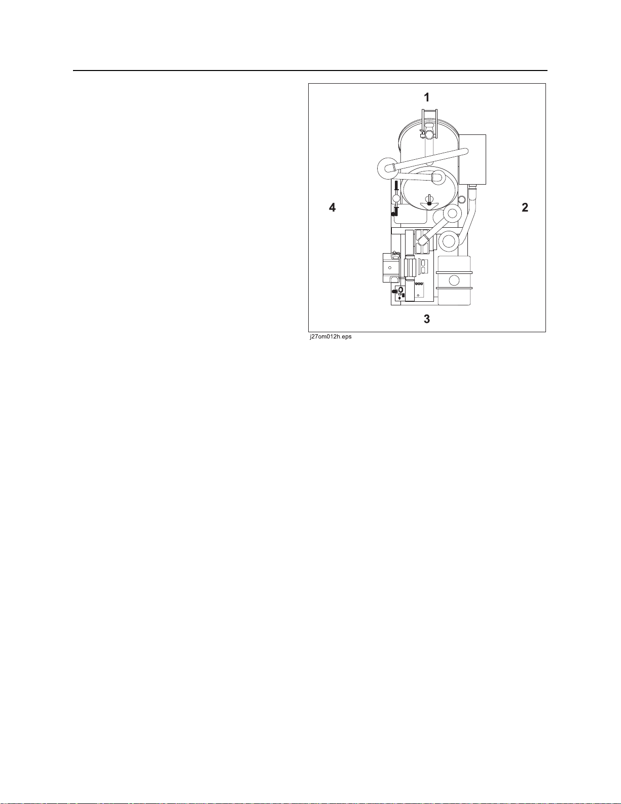
Operator Orientation
Operator Orientation
1. Rear of unit
2. Left of unit
Right and left sides of machine are determined
by facing towing vehicle.
3. Front of unit
4. Right of unit
About This Manual
This manual contains information for the proper use of this machine. See Operation Overview for basic
operating procedures. Cross references such as “See page 50” will direct you to detailed procedures.
Bulleted Lists
Bulleted lists provide helpful or important information or contain procedures that do not have to be
performed in a specific order.
Numbered Lists
Numbered lists contain illustration callouts or list steps that must be performed in order.
CMW

FX20 Operator’s Manual Foreword - 5
Reporting Safety Defects (Trailer-Mounted Units)
Foreword
This manual is an important part of your equipment. It provides safety information and operation
instructions to help you use and maintain your Ditch Witch equipment.
Read this manual before using your equipment. Keep it with the equipmen t at all times for future reference.
If you sell your equipment, be sure to give this manual to the new owner.
If you need a replacement copy, contact your Ditch Witch dealer. If you need assistance in locating a
dealer, visit our website at www.ditchwitch.com or write to the following address:
The Charles Machine Works, Inc.
Attn: Marketing Department
PO Box 66
Perry, OK 73077-0066
USA
The descriptions and specifications in this manual are subject to change without notice. The Charles
Machine Works, Inc. reserves the right to improve equipment. Some product improvements may have
taken place after this manual was publishe d. For the latest information on Ditch Witch equipment, see your
Ditch Witch dealer.
Thank you for buying and using Ditch Witch equipment.
Reporting Safety Defects (Trailer-Mounted Units)
If you believe that your vehicle has a defect which could cau se a cr ash o r co uld ca use injury or death, you
should immediately inform the National Highway Traffic Safety Administration (NHTSA) in addition to
notifying the Product Safety Coordinator at The Charles Machine Works, Inc.
If NHTSA receives similar complaints, it may open an investigation, and if it finds that a safety defect exists
in a group of vehicles, it may order a recall and remedy campaign. However, NHTSA cannot become
involved in any individual problems between you, your Ditch Witch dealer, or The Charles Machine Works,
Inc.
To contact NHTSA you may either call the Auto Safety Hotline toll-free at 1-888-327-4236 (TTY: 1-800424-9153), go to http://www.safercar.gov, or write to:
Administrator
NHTSA
1200 New Jersey Avenue S.E.
Washington, DC 20590
You can also obtain other information about motor vehicle safety from http://www.safe rcar.gov.
CMW

Foreword - 6 FX20 Operator’s Manual
FX20
Operator’s Manual
Issue number 1.1/OM-6/08
Part number 053-1270
Copyright 2008
by The Charles Machine Works, Inc.
, Ditch Witch, CMW, AutoCrowd, Jet Trac, Roto Witch, Subsite, Fluid Miser,
Power Pipe, Super Witch, Pierce Airrow, The Underground, The Underground Authority Worldwide, and
Zahn are registered trademarks of The Ch ar les Mac hin e Works, Inc.
U.S. patents pending.
CMW
FX20 Operator’s Manual Contents - 7
Content s
Overview
machine serial number, information about the type of work this machine is designed
to perform, basic machine components, and how to use this manual
Foreword
part number, revision level, and publication date of this manual, and factory contact
information
Safety
machine safety alerts and emergency procedures
Controls
machine controls, gauges, and indicators and how to use them
Operation Overview
an overview for completing a job with this machine: planning, setting up, vacuuming,
potholing, and restoring the jobsite; with cross references to detailed procedures
Prepare
procedures for inspecting and classifying the jobsite, and preparing the jobsite for
work
Transport
procedures for lifting and hauling
1
5
9
19
27
31
37
Vacuum and Pothole
procedures for removing debris and potholing utility locations
Complete the Job
procedures for restoring the jobsite and rinsing and storing equipment
Service
service intervals and instructions for this machine including lubrication, replacement
of wear items, and basic maintenance
Specifications
machine specifications including weights, measurements, power ratings, and fluid
capacities
Support
the warranty policy for this machine, and procedures for obtaining warranty
consideration and training
43
51
55
81
87
CMW

Contents - 8 FX20 Operator’s Manual
Service Record
a record of major service performed on the machine
91
CMW

FX20 Operator’s Manual Safety - 9
Safety
Chapter Contents
Guidelines . . . . . . . . . . . . . . . . . . . . . . . . . . . . . . . . 10
Safety Alert Classifications . . . . . . . . . . . . . . . . . . 11
Safety Alerts . . . . . . . . . . . . . . . . . . . . . . . . . . . . . . 12
Emergency Procedures . . . . . . . . . . . . . . . . . . . . . 15
• Electric Strike Description. . . . . . . . . . . . . . . . . . . . . . . . . . . . . . . . . . . .15
• If an Electric Line is Damaged . . . . . . . . . . . . . . . . . . . . . . . . . . . . . . . .16
• If a Gas Line is Damaged . . . . . . . . . . . . . . . . . . . . . . . . . . . . . . . . . . . .17
• If a Fiber Optic Cable is Damaged . . . . . . . . . . . . . . . . . . . . . . . . . . . . .17
• If Machine Catches on Fire. . . . . . . . . . . . . . . . . . . . . . . . . . . . . . . . . . .17
CMW

Safety - 10 FX20 Operator’s Manual
Guidelines
Guidelines
Follow these guidelines before operating any jobsite equipment:
• Complete proper training and read operator’s manual before using equipment.
• Contact your local One-Call (811 in USA) or the One-Call referral number (888-258-0808 in USA and
Canada) to have underground utilities located before digging. Also contact any utilities that do not
participate in the One-Call service.
• Classify jobsite based on its hazards and use cor rect tools and machin ery, safety equipment, and work
methods for jobsite.
• Mark jobsite clearly and keep spectators away.
• Wear personal protective equipment.
• Review jobsite hazards, safety and emergency procedures, and individual responsibilities with all
personnel before work begins. Safety videos are available from your Ditch Witch dealer.
• Replace missing or damaged safety shields and safety signs.
• Use equipment carefully. Stop operation and investigate anything that does not look or feel right.
• Do not operate unit where flammable gas may be present.
• Contact your Ditch Witch dealer if you have any question about operation, ma intenance, or equipment
use.
CMW
FX20 Operator’s Manual Safety - 11
Safety Alert Classifications
Safety Alert Classifications
These classifications and the icons defined on the following pages work together to alert you to situations
which could be harmful to you, jobsite bystanders or your equipment. When you see these words and
icons in the book or on the machine, carefully read and follow all instructions. YOUR SAFETY IS AT
STAKE.
Watch for the three safety alert levels: DANGER, WARNING and CAUTION. Learn what each level
means.
indicates an imminently hazardous situation which, if not avoided, will result in death or
serious injury.
indicates a potentially hazardous situation which, if not avoided, could result in death or
serious injury.
indicates a potentially hazardous situation which, if not avoided, may result in minor or
moderate injury.
Watch for two other words: NOTICE and IMPORTANT.
NOTICE can keep you from doing something that might damage the machine or someone's property. It
can also alert you against unsafe practices.
IMPORTANT can help you do a better job or make your job easier in some way.
CMW
Safety - 12 FX20 Operator’s Manual
Safety Alerts
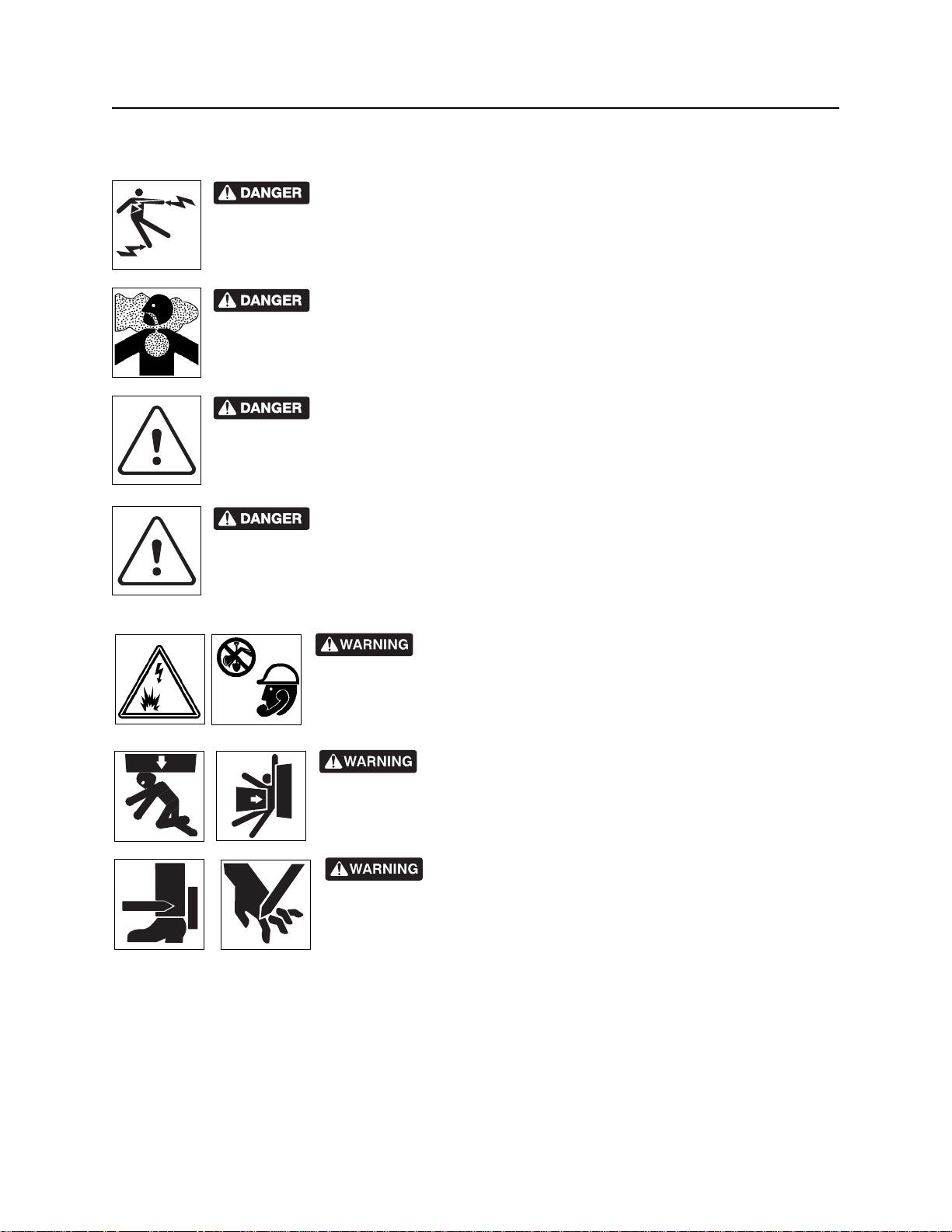
Safety Alerts
Electric shock. Contacting electric lines will cause death or serious injury.
Know location of lines and stay away.
Deadly gases. Lack of oxygen or presence of gas will cause sickness or
death. Provide ventilation.
Confined space will cause suffocation. Use proper procedures for entering
or stay away.
Vacuum will suffocate. Maintain distance between face and vacuum inlets.
Jobsite hazards could cause death or serious injury. Use
correct equipment and work methods. Use and maintain proper safety
equipment.
Crushing weight could cause death or seriou s injur y. Use
proper procedures and equipment or stay away.
Moving parts could cut off hand or foot. Stay away.
CMW
FX20 Operator’s Manual Safety - 13
Safety Alerts
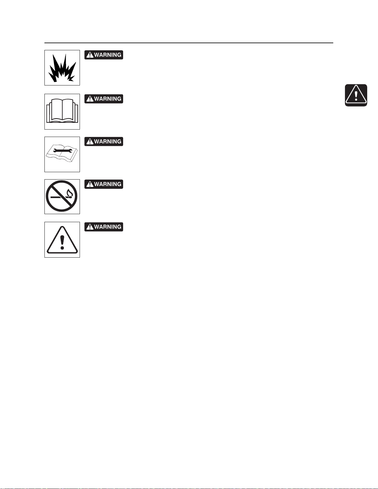
Explosion possible. Serious injury or equipment damage could occur.
Follow directions carefully .
Incorrect procedures could result in death, injury, or property damage.
Learn to use equipment correctly.
Improper control function could cause death or serious injury. If control does
not work as described in instructions, stop machine and have it serviced.
Fire or explosion possible. Fumes could ignite and cause burns. No
smoking, no flame, no spark.
Moving traffic - hazardous situation. Death or serious injury could result.
Avoid moving vehicles, wear high visibility clothing, post appropriate warning signs.
CMW
Safety - 14 FX20 Operator’s Manual
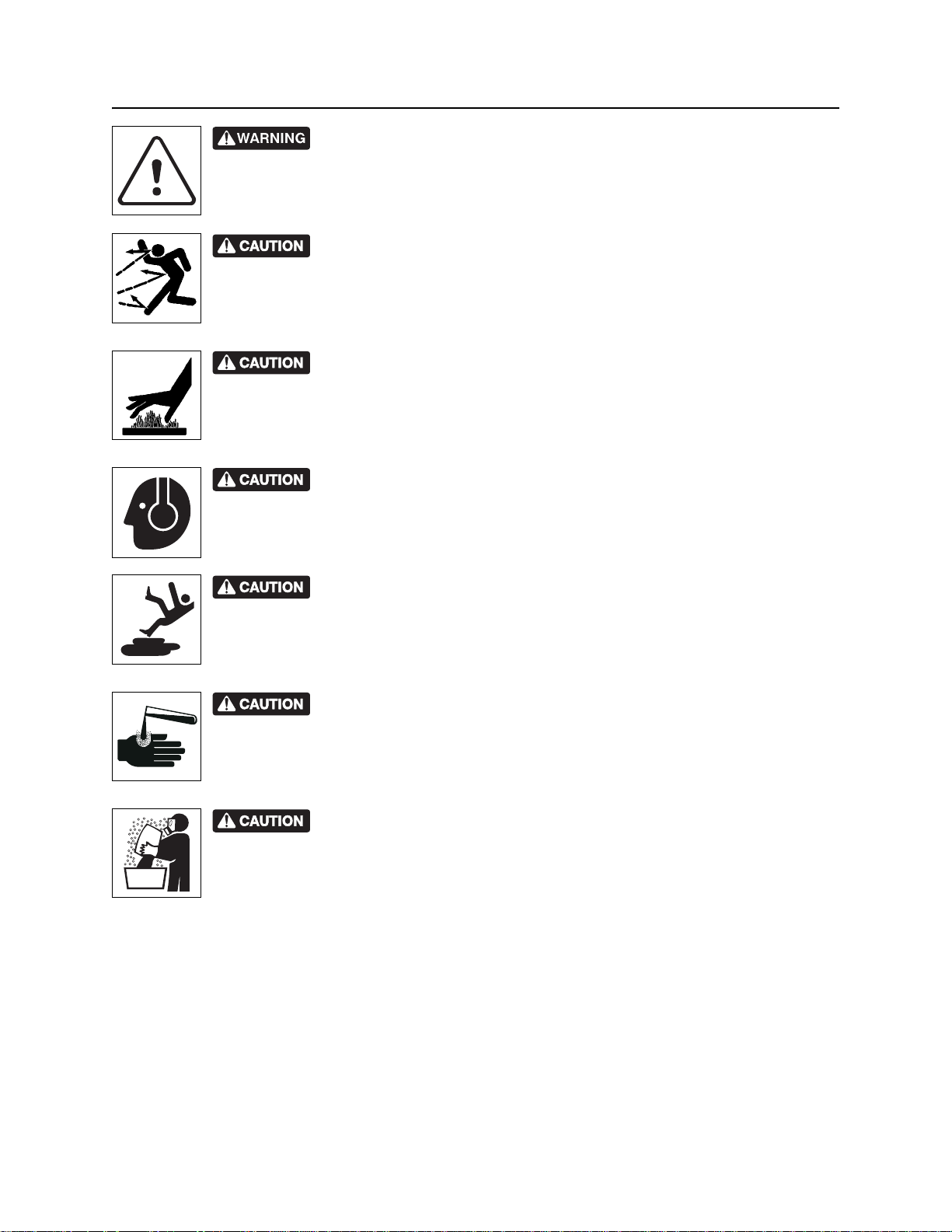
Safety Alerts
Hot pressurized cooling system fluid could cause serious burns. Allow to
cool before servicing.
Flying objects may cause injury. Wear hard hat and safety glasses.
Hot parts may cause burns. Do not touch until cool.
Exposure to high noise levels may cause hearing loss. Wear hearing
protection.
Fall possible. Slips or trips may result in injury. Keep area clean.
Battery acid may cause burns. Avoid contact.
Improper handling or use of chemicals may result in illness, injury, or
equipment damage. Follow instructions on labels and in material safety data sheets
(MSDS).
CMW
FX20 Operator’s Manual Safety - 15
Emergency Procedures
Emergency Procedures
Jobsite hazards could cause death or serious injury. Use
correct equipment and work methods. Use and maintain proper safety
equipment.
Before operating any equipment, review emergency proc edures and check that all safety precau tions have
been taken.
EMERGENCY SHUTDOWN - Turn ignition switch to stop position or push remote e ngine stop button ( if
equipped).
Electric Strike Description
Electric shock. Contacting electric lines will cause death or serious injury.
Know location of lines and stay away.
When working near electric cables, remember the following:
• Electricity follows all paths to ground, not just path of least resistance.
• Pipes, hoses, and cables will conduct electricity back to all equipment.
• Low voltage current can injure or kill. Almost one-third of work-related electrocutions result from
contact with less than 440 volts.
Most electric strikes are not noticeable, but indications of a strike include:
• power outage
•smoke
•explosion
• popping noises
• arcing electricity
If any of these occur, assume an electric strike has occurred.
CMW

Safety - 16 FX20 Operator’s Manual
Emergency Procedures
If an Electric Line is Damaged
If you suspect an electric line has been damaged and you are on truck or trailer, DO NOT MOVE.
Remain on truck or trailer and take the following actions. The order and degree of action will depend on the
situation.
• Warn people nearby that an electric strike has occurred. Instruct them to leave the area and contact
utility.
• Do not allow anyone into area until given permission by utility company.
• Do not allow anyone to touch equipment.
If you suspect an electric line has been damaged and you are off truck or trailer, DO NOT TOUCH
EQUIPMENT. Take the following actions. The order and degree of action will depend on the situation.
• LEAVE AREA.
• Contact utility company to shut off power.
• Do not return to area or allow anyone into area until given permission by utility company.
CMW
FX20 Operator’s Manual Safety - 17
Emergency Procedures
If a Gas Line is Damaged
Fire or explosion possible. Fumes could ignite and cause burns. No
smoking, no flame, no spark.
Explosion possible. Serious injury or equipment damage could occur.
Follow directions carefully.
If you suspect a gas line has been damaged, take the following actions. The order and degree of action will
depend on the situation.
• Immediately shut off engine(s), if this can be done safely and quickly.
• Remove any ignition source(s), if this can be done safely and quickly.
• Warn others that a gas line has been cut and that they should leave the area.
• Leave jobsite as quickly as possible.
• Immediately call your local emergency phone number and utility company.
• If jobsite is along street, stop traffic from driving near jobsite.
• Do not return to jobsite until given permission by emergency personnel and utility company.
If a Fiber Optic Cable is Damaged
Do not look into cut ends of fiber optic or unidentified cable. Vision damage can occur.
If Machine Catches on Fire
Perform emergency shutdown procedure and then take the following actions. The order and degree of
action will depend on the situation.
• Immediately move battery disconnect switch (if equipped) to disconnect position.
• If fire is small and fire extinguisher is available, attempt to extinguish fire.
• If fire cannot be extinguished, leave area as quickly as possible and contact emergency personnel.
CMW

Safety - 18 FX20 Operator’s Manual
Emergency Procedures
CMW

FX20 Operator’s Manual Controls - 19
Controls
Chapter Contents
Engine/Operator’s Station . . . . . . . . . . . . . . . . . . . 20
Machine Controls . . . . . . . . . . . . . . . . . . . . . . . . . . 23
CMW
Controls - 20 FX20 Operator’s Manual
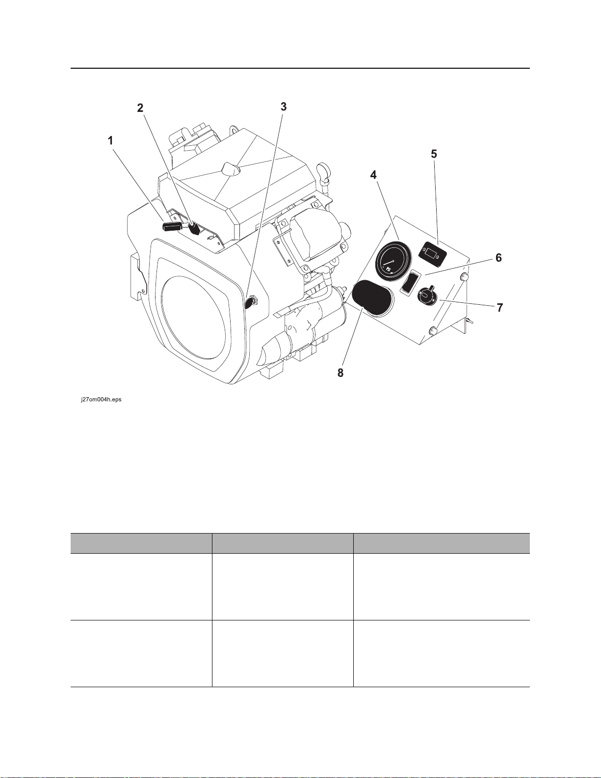
Engine/Operator’s Station
Engine/Operator ’s Station
1. Throttle
2. Choke
3. Ignition switch
4. Water pressure gauge
Item Description Notes
1. Throttle To increase engine speed,
move left.
To decrease engine speed,
move right.
2. Choke To choke cold engine, move
left.
To operate normally, move
right.
5. Hourmeter
6. Water pump switch
7. Auxiliary outlet
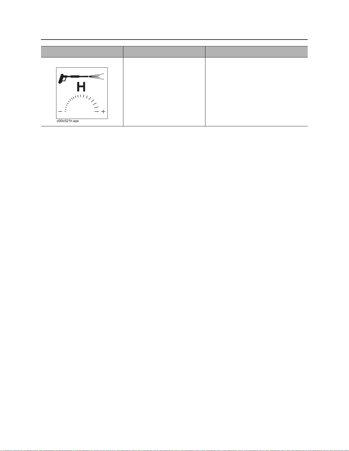
8. Water pressure control
NOTICE: Set engine speed to full
throttle before turning off engine.
CMW
FX20 Operator’s Manual Controls - 21
Engine/Operator’s Station
Item Description Notes
3. Ignition switch T o star t engine, insert key and
turn clockwise.
To stop engine, turn key
counterclockwise.
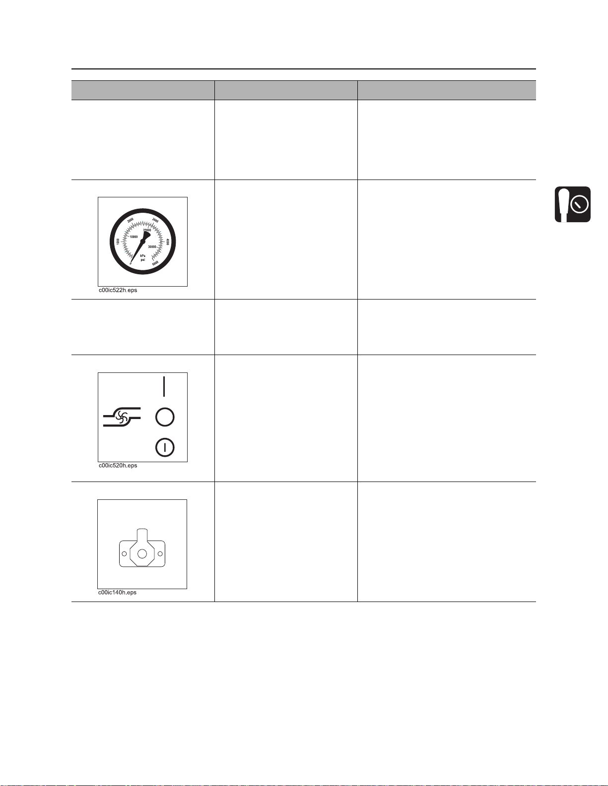
4. Water pressure gauge Displays water pressure
when water pressure switch
is on and water lance is in
use.
5. Hourmeter Displays engine operating
time.
6. Water pump switch To turn on water pump, press
top.
IMPORTANT: When engine is on,
blower operates and vacuum is
present at tank inlet.
NOTICE: Set engine speed to full
throttle before turning off engine.
Hourmeter runs when ignition switch
is on.
Use these times to schedule service.
To turn off water pump, move
to center position.
To bypass low water
indication, press bottom.
7. Auxiliary outlets To operate work lights or
other 12V devices, plug into
outlet.
Use bypass to feed antifreeze into
system when freshwater tank is
empty. See “Add Antifreeze” on
page 52.
Outlet has power only when ignition
switch is on.
CMW
Controls - 22 FX20 Operator’s Manual
Engine/Operator’s Station
Item Description Notes
8. Water pressure control To increase water pressure,
turn clockwise.
To decrease water pressure,
turn counterclockwise.
CMW
FX20 Operator’s Manual Controls - 23
Machine Controls
Machine Controls
1. Debris tank sight glass
2. Inlet valve
3. Cyclonic filter sight glass
4. Battery disconnect switch
5. Vacuum gauge
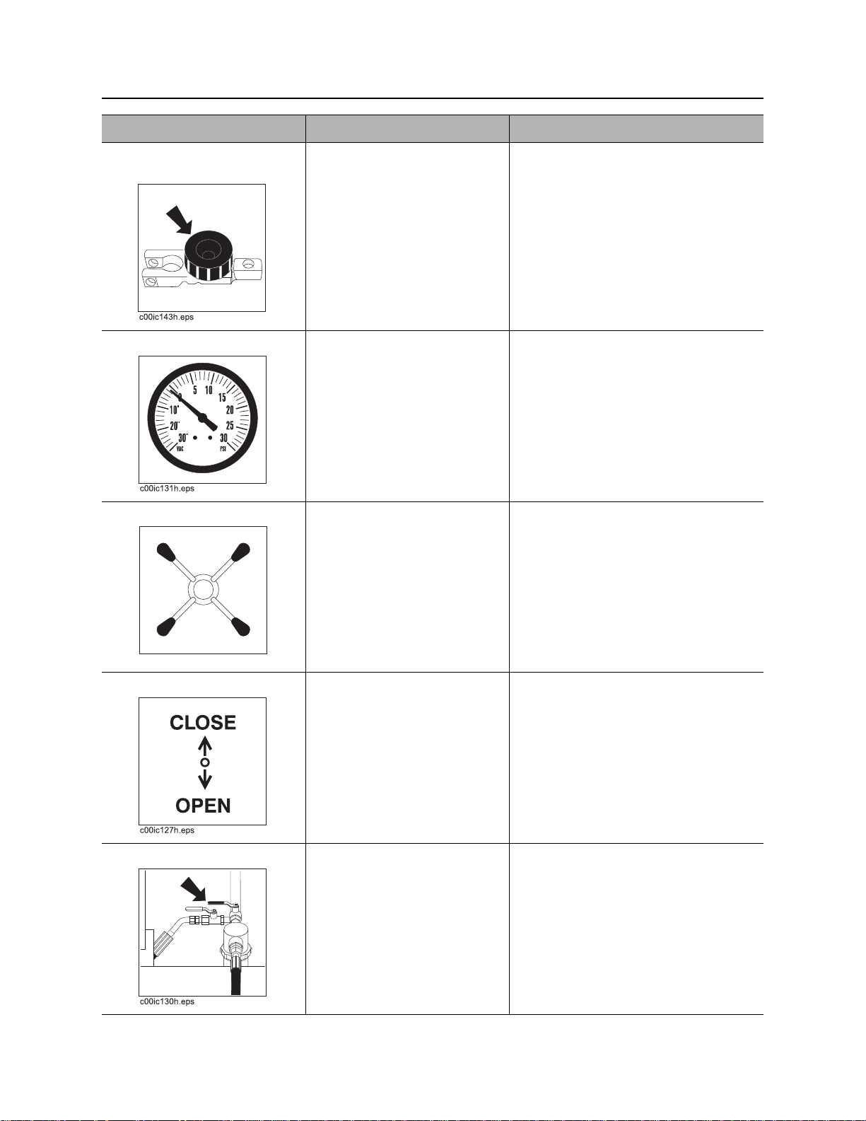
Item Description Notes
1. Debris tank sight glass
2. Inlet valve To close valve (stop suction),
rotate up.
To open valve (start suction),
rotate down.
3. Cyclonic filter sight
glass
6. Tank door handle
7. Drain valve
8. Water tank drain valve
9. Antifreeze tank supply valve
10. Water tank supply valve
CMW
Controls - 24 FX20 Operator’s Manual
Machine Controls
Item Description Notes
4. Battery disconnect
To connect, turn clockwise.
switch
To disconnect, turn
counterclockwise.
5. Vacuum gauge Displays blower vacuum
reading in inches of mercury.
Vacuum relief valve opens
when vacuum reaches 15”
(381 mm).
6. Tank door handle To close tank door, turn
clockwise several times.
To open tank door, turn
counterclockwise several
times.
IMPORTANT: Use battery disconnect
switch when servicing, welding, and
during long-term storage.
IMPORTANT: Do not push on door
when closing with handle.
c00ic176h.eps
7. Drain valve To drain tank, rotate down.
To close drain, rotate up.
8. Water t ank supply va lve To open valve (send water
from the water tank through
the pump and water lance),
rotate counterclockwise.
To close valve (stop water
flow), rotate clockwise.
CMW
IMPORTANT: Water tank supply
valve or antifreeze supply valve must
be open when pump is running or
pump will be damaged.
FX20 Operator’s Manual Controls - 25
Machine Controls
Item Description Notes
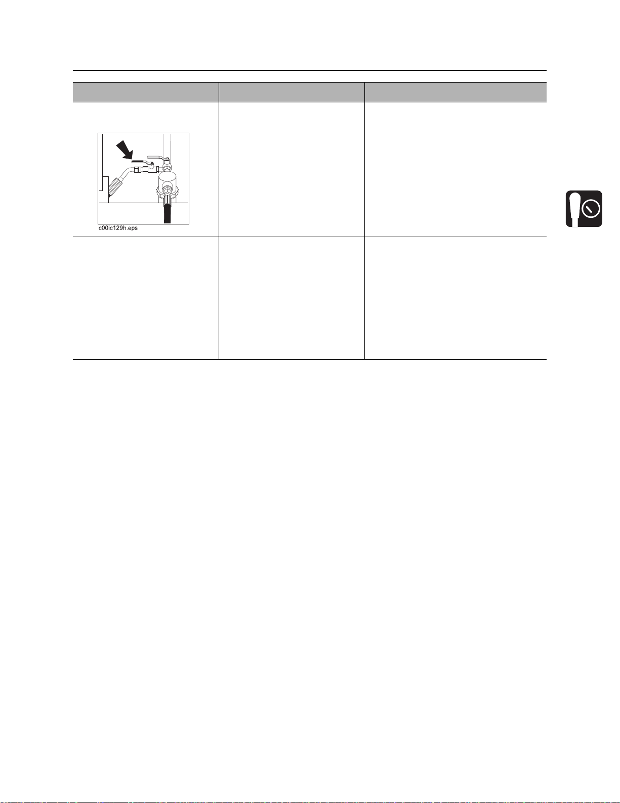
9. Antifreeze tank supply
valve
10. Water tank drain valve To drain tank, open valve.
To open valve (send
antifreeze through pump and
water lance), rotate
counterclockwise.
To close valve (stop
antifreeze flow), rotate
clockwise.
Close valve when tank is
empty.
IMPORTANT:
• Water tank supply valve or
antifreeze supply valve must be
open when pump is running or
pump will be damaged.
• Close supply valve when using
antifreeze valve.
CMW

Controls - 26 FX20 Operator’s Manual
Machine Controls
CMW

FX20 Operator’s Manual Operation Overview - 27
Operation Overview
Chapter Contents
Planning . . . . . . . . . . . . . . . . . . . . . . . . . . . . . . . . . 28
Setting Up at Jobsite . . . . . . . . . . . . . . . . . . . . . . . 28
Vacuuming . . . . . . . . . . . . . . . . . . . . . . . . . . . . . . . 28
Potholing . . . . . . . . . . . . . . . . . . . . . . . . . . . . . . . . 29
Leaving Jobsite . . . . . . . . . . . . . . . . . . . . . . . . . . . 29
Storing Equipment . . . . . . . . . . . . . . . . . . . . . . . . . 29
CMW

Operation Overview - 28 FX20 Operator’s Manual
Planning
Planning
1. Gather information about jobsite (page 32).
2. Inspect jobsite (page 33).
3. Check supplies and prepare equipment (page 35).
Setting Up at Jobsite
1. Prepare jobsite (page 34).
2. Position vacuum excavation unit.
3. Leave unit hitched to towing vehicle or properly stabilized if trailer-mounted unit.
4. Block trailer wheels if trailer-mounted unit.
Vacuuming
1. Connect hoses (page 44).
2. Start unit (page 44).
3. Remove debris (page 45).
4. Disconnect hoses.
5. Drain tank (page 48).
CMW

FX20 Operator’s Manual Operation Overview - 29
Potholing
Potholing
1. Connect hoses (page 44).
2. Start unit (page 44).
3. Pothole (page 46).
4. Disconnect hoses.
5. Drain tank (page 48).
Leaving Jobsite
1. Rinse unit and tools (page 53).
2. Stow tools (page 53).
Storing Equipment
1. For cold weather storage, antifreeze vacuum excavation unit (page 52) .
2. For long-term storage, disconnect battery disconnect switch (page 23).
CMW

Operation Overview - 30 FX20 Operator’s Manual
Storing Equipment
CMW

FX20 Operator’s Manual Prepare - 31
Prep are
Chapter Contents
Gather Information . . . . . . . . . . . . . . . . . . . . . . . . . 32
• Arrange for Traffic Control . . . . . . . . . . . . . . . . . . . . . . . . . . . . . . . . . . .32
• Prepare for Working Near Existing Utilities . . . . . . . . . . . . . . . . . . . . . .32
• Plan for Emergency Services . . . . . . . . . . . . . . . . . . . . . . . . . . . . . . . . .32
Inspect Jobsite . . . . . . . . . . . . . . . . . . . . . . . . . . . . 33
Prepare Jobsite . . . . . . . . . . . . . . . . . . . . . . . . . . . 34
• Prepare Excavation Point . . . . . . . . . . . . . . . . . . . . . . . . . . . . . . . . . . . .34
Check Supplies and Prepare Equipment . . . . . . . 35
• Assemble Accessories . . . . . . . . . . . . . . . . . . . . . . . . . . . . . . . . . . . . . .35
• Check Supplies . . . . . . . . . . . . . . . . . . . . . . . . . . . . . . . . . . . . . . . . . . .35
• Prepare Equipment . . . . . . . . . . . . . . . . . . . . . . . . . . . . . . . . . . . . . . . .36
CMW

Prepare - 32 FX20 Operator’s Manual
Gather Information
Gather Information
A successful job begins before the excavation. The first step in planning is reviewing information already
available about the job and jobsite.
Arrange for Traffic Control
If working near a road or other traffic area, contact local authorities about safety procedures and
regulations.
Prepare for Working Near Existing Utilities
If jobsite may contain electrical lines, wear protective boots and gloves meeting the following standards:
• Boots must have high tops and meet the electric hazard protection requirements of ANSI Z-41, 1991,
when tested at 14,000 volts. Tuck legs of pants completely inside boots.
• Gloves must have 17,000 AC maximum use voltage, according to ASTM spec ifica tio n D12 0-8 7.
If working around higher voltage, use gloves and boots with appropriately higher ratings.
Plan for Emergency Services
Have the telephone numbers for local emergency and medical facilities on hand. Check that you will have
access to a telephone.
CMW

FX20 Operator’s Manual Prepare - 33
Inspect Jobsite
Inspect Jobsite
• Follow U.S. Department of Labor regulations on excavating and trenching (Part 1926, Subpar t P) and
other similar regulations.
• Contact your local One-Call (811 in USA) or the One-Call referral number (888-258-0808 in USA and
Canada) to have underground utilities located before working. Also contact any utilities that do not
participate in the One-Call service.
• Inspect jobsite and perimeter for evidence of underground hazards, such as:
– “Buried utility” notices
– Utility facilities without overhead lines
– Gas or water meters
– Junction boxes
– Drop boxes
– Light poles
– Manhole covers
– Sunken ground
• Mark location of all buried utilities and obstructions.
CMW

Prepare - 34 FX20 Operator’s Manual
Prepare Jobsite
Prepare Jobsite
Jobsite hazards could cause death or serious injury. Use
correct equipment and work methods. Use and maintain proper safety
equipment.
NOTICE:
• If jobsite classification is in question or if the possibility of unmarked electric utilities exists, classify
jobsite as electric.
• Cutting high voltage cable can cause electrocution. Expose lines by hand before using unit.
• All vegetation near operator’s station must be removed. Conta ct with trees, shrubs, or weeds during
electrical strike could result in electrocution.
Prepare Excavation Point
• Clear the area to be excavated. Remove rocks or branches too large for vacuum hose.
• If excavating fluids while drill string is moving, clear area of trees, shrubs, and weeds.
• Select a solid area to stand on while excavating.
CMW

FX20 Operator’s Manual Prepare - 35
Check Supplies and Prepare Equipment
Check Supplies and Prepare Equipment
Assemble Accessories
Fire Extinguisher
If required, mount a fire extinguisher near the power unit but away from possible points of ignition. The fire
extinguisher should always be classified for both oil and electric fires. It should meet legal and regulatory
requirements.
Lighting Kit
If you will need additional light, plug lighting kit into provided outlet. Contact your Ditch Witch dealer for
further information.
Check Supplies
• water and additional hoses
•fuel
•keys
• spray lubricant
• personal protective equipment, such as hard hat and safety glasses
CMW

Prepare - 36 FX20 Operator’s Manual
Check Supplies and Prepare Equipment
Prepare Equipment
Fluid Levels
•fuel
•battery
• engine oil
• blower oil
Condition and Function
• filters (air, oil)
•belts
• blower
•tires
• hoses and valves
• couplers and fittings
• water tanks
• trailer parking brake (trailer-mounted unit)
CMW

FX20 Operator’s Manual Transport - 37
Transport
Chapter Contents
Lift . . . . . . . . . . . . . . . . . . . . . . . . . . . . . . . . . . . . . . 38
• Points . . . . . . . . . . . . . . . . . . . . . . . . . . . . . . . . . . . . . . . . . . . . . . . . . . .38
• Procedure . . . . . . . . . . . . . . . . . . . . . . . . . . . . . . . . . . . . . . . . . . . . . . . .38
Attach Skid to Trailer . . . . . . . . . . . . . . . . . . . . . . . 39
Attach Skid to Truck Bed . . . . . . . . . . . . . . . . . . . . 39
Haul . . . . . . . . . . . . . . . . . . . . . . . . . . . . . . . . . . . . . 40
• Inspect Trailer . . . . . . . . . . . . . . . . . . . . . . . . . . . . . . . . . . . . . . . . . . . .40
• Hitch Trailer . . . . . . . . . . . . . . . . . . . . . . . . . . . . . . . . . . . . . . . . . . . . . .40
• Unhitch Trailer . . . . . . . . . . . . . . . . . . . . . . . . . . . . . . . . . . . . . . . . . . . .41
CMW

Transport - 38 FX20 Operator’s Manual
Lift
Lift
Crushing weight. If load falls or moves it could kill or crush you. Use
proper procedures and equipment or st ay away.
Points
Lifting points are identified by lifting decals. Lifting at other points is unsafe
and can damage machinery.
Procedure
Use a crane capable of supporting the
equipment's size and weight. See “S pecifications”
on page 81 or measure and weigh equipment
before lifting. Use top lift point as shown.
IMPORTANT: Lift unit only when debris and
water tanks are empty.
CMW

FX20 Operator’s Manual Transport - 39
Attach Skid to Trailer
Attach Skid to Trailer
Bolt skid to S4S trailer at 4 locations. Use bolt and
nut (1,2) to secure. Tighten to 200-225 ft•lb (270305 N•m). Install light strip to rear of tank using
bolts and nuts (3,4). Connect wiring harness from
light strip to connector (5).
IMPORTANT: See parts manual for correct bolt
size and grade.
Attach Skid to Truck Bed
Use indicated tiedowns to secure skid to truck
bed. Be sure to tie down both front and rear of
unit. The skid can also be bolted to a truck bed
using the 4 holes indicated above.
NOTICE: Use a chain, not a strap, if using the
lift/tiedown point on top of the tank.
CMW

Transport - 40 FX20 Operator’s Manual
Haul (Trailer-Mounted Unit)
Haul (Trailer-Mounted Unit)
Crushing weight. If load falls or moves it could kill or crush you. Use
proper procedures and equipment or st ay away.
Inspect Trailer
• Check hitch for wear and cracks. Lubricate if needed.
• Inspect lights for cleanliness and correct operation. Inspect reflectors and replace if needed.
• Check tire pressure. Check lug nut torque with a torque wrench.
Hitch Trailer
1. Back tow vehicle to trailer.
2. Put manual transmission into first or reverse gear or automatic transmission into park. Turn off ignition.
Set parking brake.
3. Connect trailer coupler to tow vehicle hitch and lock in place with lock pin. If needed, adjust coupler
height to level load.
4. Connect safety chains to tow vehicle chain
keepers (cross-shaped slots on bumper of
tow vehicle). Attach left chain to right side of
tow vehicle and vice versa to cradle hitch. Do
not connect to pintle hook or hitch ball.
5. Connect emergency parking brake cable to
tow vehicle and pull handle back as shown.
6. Plug trailer electrical connector into tow
vehicle connector.
7. Use jack crank to raise jack base and stow.
8. Remove wheel blocks.
CMW

FX20 Operator’s Manual Transport - 41
Haul (Trailer-Mounted Unit)
Unhitch Trailer
1. Stop tow vehicle an d trailer on level ground.
2. Put manual transmission into first or reverse gear or automatic transmission into park. Turn off ignition.
Set parking brake.
3. Block trailer wheels or set trailer emergency parking brake.
4. To unhitch trailer from tow vehicle, reverse “Hitch Trailer“ steps.
CMW

Transport - 42 FX20 Operator’s Manual
Haul (Trailer-Mounted Unit)
CMW

FX20 Operator’s Manual Vacuum and Pothole - 43
Vacuum and Pothole
Chapter Contents
Connect Hoses . . . . . . . . . . . . . . . . . . . . . . . . . . . . 44
Start Unit . . . . . . . . . . . . . . . . . . . . . . . . . . . . . . . . . 44
Remove Debris . . . . . . . . . . . . . . . . . . . . . . . . . . . . 45
• Procedure . . . . . . . . . . . . . . . . . . . . . . . . . . . . . . . . . . . . . . . . . . . . . . . .45
Pothole . . . . . . . . . . . . . . . . . . . . . . . . . . . . . . . . . . 46
Drain Tank . . . . . . . . . . . . . . . . . . . . . . . . . . . . . . . . 48
CMW

Vacuum and Pothole - 44 FX20 Operator’s Manual
Connect Hoses
Connect Hoses
1. Remove vacuum hoses from storage.
2. If potholing, remove potholing tool from storage.
3. Connect hoses. Secure all locking clamps.
4. Ensure inlet and drain valves are closed.
5. If potholing, connect water pressure hose (shown).
Start Unit
EMERGENCY SHUTDOWN: Turn ignition switch to STOP.
1. Insert key.
2. Choke engine if necessary. See page 20 for more information.
3. Turn key clockwise. See page 21 for more information.
4. Run engine at low throttle for 5 minutes.
IMPORTANT: Engine will not run at low idle when inlet valve is closed.
CMW

FX20 Operator’s Manual Vacuum and Pothole - 45
Remove Debris
Remove Debris
EMERGENCY SHUTDOWN: Turn ignition switch to STOP.
Procedure
1. Position vacuum hose in area to be excavated.
2. Start engine.
Vacuum will suffocate. Maintain distance between face and
vacuum inlets.
Fire or explosion possible. Do not vacuum flammable or
combustible substances.
3. Open inlet valve if necessary to begin exc avation.
Incorrect procedures could result in death, injury, or property
damage. Learn to use equipment correctly.
NOTICE: Do not excavate hazardous or toxic materials. Unit is designed to excavate only soil
cuttings, drilling fluids, and other non-toxic waste.
4. Use sight glass to monitor liquid debris level in tank. Vacuum will shut off when tank is full. Engine will
remain running.
Watch debris tank and cyclone sight glasses to determine when tank is full of dry debris. Shut off
engine.
IMPORTANT: Do not overfill debris tank.
CMW

Vacuum and Pothole - 46 FX20 Operator’s Manual
Pothole
Pothole
EMERGENCY SHUTDOWN: Turn ignition switch to STOP.
1. Start engine.
Vacuum will suffocate. Maintain distance between face and
vacuum inlets.
Fire or explosion possible. Do not vacuum flammable or
combustible substances.
2. Open water tank valve.
3. Move water pump switch to on. It might be necessary to prime the pump if water level is low. See
“Prime Water Pump” o n page 47.
4. Open inlet valve if necessary.
5. Position tool over area to be excavated and begin pothole.
Electric shock. Contacting electric lines will cause death or
serious injury. Know location of lines and stay away.
NOTICE: Do not direct water lance at overhead lines. Water conducts electricity.
• First use water lance to loosen soil.
• Work tool in a rocking or circular motion to excavate soil.
• Use water lance and tool alternately until hole is at the desired diameter and depth.
CMW

FX20 Operator’s Manual Vacuum and Pothole - 47
Pothole
6. Adjust water pressure as needed to match soil conditions and/or material of utility being exposed.
Jobsite hazards could cause death or serious injury. Use
correct equipment and work methods. Use and maintain proper safety
equipment.
NOTICE: High pressure water can cut utility lines. Test water pressure on a sample of the
material to be located. Adjust pressure until no damage occurs to the material.
7. Ensure that water sprays from nozzle in a fan pattern. If it does not, nozzle may be clogged and pump
will not function properly. Clean or replace nozzle as necessary.
8. Water pump will shut off when freshwater tank is empty.
Prime Water Pump
Loosen joint (shown) to start water flow. Tighten
after water begins flowing.
CMW

Vacuum and Pothole - 48 FX20 Operator’s Manual
Drain Tank
Drain Tank
EMERGENCY SHUTDOWN: Turn ignition switch to STOP.
1. Ensure that unit is hitched to vehicle for trailer-mounted units. See “Hitch Trailer” on page40.
2. Haul unit to approved dumping area.
3. Open drain valve and inlet valve.
4. Open tank door.
• Turn t ank door handle (1)
counterclockwise to loosen door.
• Turn off engine. Tank door will open when
vacuum is relieved.
• Pull door open and guide door prop (2)
until it engages stop as shown.
CMW

FX20 Operator’s Manual Vacuum and Pothole - 49
Drain Tank
5. Allow tank to drain completely.
6. Connect water pressure hose to water lance.
7. Turn water pump switch on. Adjust water pressure.
8. Use water lance to thoroughly rinse inside of tank and around door seal.
Confined space will cause suffocation. Use proper procedures
for entering or stay away.
NOTICE: Enter tank only if necessary. Follow U.S. Department of Labor
guidelines for entering confined spaces.
9. Close tank door.
• Lift door until door prop (3) clears stop
(2). Slide prop to stowed position as
shown.
• Start engine. This will pull a vacuum and
cause door to pull toward tank.
• Turn door handle (1) clockwise 9-1 1 turns
to tighten door against seal.
IMPORTANT: Do not lean on door, prop
or other handles when tightening door to
avoid misalignment.
CMW

Vacuum and Pothole - 50 FX20 Operator’s Manual
Drain Tank
CMW

FX20 Operator’s Manual Complete the Job - 51
Complete the Job
Chapter Contents
Antifreeze Vacuum Excavation Unit . . . . . . . . . . . 52
• Add Antifreeze . . . . . . . . . . . . . . . . . . . . . . . . . . . . . . . . . . . . . . . . . . . .52
• Reclaim Antifreeze . . . . . . . . . . . . . . . . . . . . . . . . . . . . . . . . . . . . . . . . .52
Rinse Equipment . . . . . . . . . . . . . . . . . . . . . . . . . . 53
Disconnect . . . . . . . . . . . . . . . . . . . . . . . . . . . . . . . 53
Stow Tools . . . . . . . . . . . . . . . . . . . . . . . . . . . . . . . 53
CMW

Complete the Job - 52 FX20 Operator’s Manual
Antifreeze Vacuum Excavation Unit
Antifreeze Vacuum Excavation Unit
Add Antifreeze
Follow these steps for overnight or long-term storage of unit during cold weather.
1. Open water tank valve and drain valve to drain all water from water tank.
2. Fill antifreeze tank with a propylene-glycol based antifreeze.
3. Close water tank valve and drain other valve.
4. Open antifreeze tank valve.
5. Connect water pressure hose to water lance.
6. Start engine.
7. Move water pump switch to on. If freshwater tank is empty, hold water pump switch in bypass position.
8. Squeeze water lance handle and run until antifreeze runs through the water lance.
9. Move water pump switch to off.
10. Close antifreeze tank supply valve.
11. Turn ignition switch to off.
12. Drain water tank completely.
Reclaim Antifreeze
1. Turn water pressure down.
2. Move water pump switch to on. If water tank is not full, use bypass position.
3. Put end of water lance in antifreeze tank.
4. Squeeze water lance handle and run until water comes out of lance.
5. Move water pump switch to off.
CMW

FX20 Operator’s Manual Complete the Job - 53
Rinse Equipment
Rinse Equipment
Spray wate r onto equipmen t to remove d irt and mud. Us e water lance . Thoroughly rins e inside of tank and
around door seal.
Confined space will cause suffocation. Use proper procedures for
entering or stay away.
NOTICE: Enter tank only if necessary. Follow U.S. Department of Labor guidelines for
entering confined spaces.
NOTICE: Do not spray water onto operator’s console. Electrical components could be damaged. Wipe
down instead.
Disconnect
Disconnect and store vacuum hose and water pressure hose.
Stow Tools
Make sure potholing tools, water lance, and other tools ar e properly stowed.
CMW

Complete the Job - 54 FX20 Operator’s Manual
Stow Tools
CMW

FX20 Operator’s Manual Service - 55
Service
Chapter Contents
Precautions . . . . . . . . . . . . . . . . . . . . . . . . . . . . . . 56
Recommended Lubricants/Service Key . . . . . . . . 56
Each Use . . . . . . . . . . . . . . . . . . . . . . . . . . . . . . . . . 58
10 Hour . . . . . . . . . . . . . . . . . . . . . . . . . . . . . . . . . . 59
25 Hour . . . . . . . . . . . . . . . . . . . . . . . . . . . . . . . . . . 65
50 Hour . . . . . . . . . . . . . . . . . . . . . . . . . . . . . . . . . . 66
100 Hour . . . . . . . . . . . . . . . . . . . . . . . . . . . . . . . . . 69
200 Hour . . . . . . . . . . . . . . . . . . . . . . . . . . . . . . . . . 71
500 Hour . . . . . . . . . . . . . . . . . . . . . . . . . . . . . . . . . 72
1000 Hour . . . . . . . . . . . . . . . . . . . . . . . . . . . . . . . . 72
2000 Hour . . . . . . . . . . . . . . . . . . . . . . . . . . . . . . . . 73
300 Mile . . . . . . . . . . . . . . . . . . . . . . . . . . . . . . . . . . 74
3000 Mile . . . . . . . . . . . . . . . . . . . . . . . . . . . . . . . . . 75
12,000 Mile . . . . . . . . . . . . . . . . . . . . . . . . . . . . . . . 76
As Needed . . . . . . . . . . . . . . . . . . . . . . . . . . . . . . . 77
CMW

Service - 56 FX20 Operator’s Manual
Precautions
Precautions
Incorrect procedures could result in death, injury, or property damage.
Learn to use equipment correctly.
NOTICES:
• Unless otherwise instructed, all service should be performed with engine off.
• Refer to engine manufacturer’s manual for engine maintenance instructions.
Recommended Lubricants/Service Key
Item Description
GEO Gasoline engine oil meeting or exceeding SG, SH, or SJ per the API service
classifications and SAE viscosity recommended by engine manufacturer (SAE 10W30)
HTG NGLI #2 premium grade, petroleum-based grease with high temperature resistance
and good mechanical stability
NDO SAE30 non-detergent oil
SGL Synthetic gear oil, ISO 100, p/n 256-044. See blower manual for more information.
MPL Multipurpose gear oil meeting API service classification GL-5 (SAE 80W90)
MPG Multipurpose grease meeting ASTM D217 and NLGI 5
Check level of fluid or lubricant
Check condition
Filter
Change, replace, adjust, service or test
Proper lubrication and maintenance protects Ditch Witch equipment from damage and failure. Service
intervals listed are for minimum requirements. In ex treme conditions, service machine more frequently.
Use only recommended lubricants. Fill to capacities listed in “Specifications” on page 121.
CMW

FX20 Operator’s Manual Service - 57
Recommended Lubricants/Service Key
For more information on engine lubrication and maintenance, see your engine manual.
NOTICE:
• Use only genuine Ditch Witch parts, filters, approved lubricants, TJC, and approved coolants to
maintain warranty.
• Use the “Service Record” on page 91 to record all required service to your machine.
Engine Oil Temperature Chart
Temperature range anticipated before next oil change
See engine manual for more information about oil viscosity and operation in arctic conditions.
CMW

Service - 58 FX20 Operator’s Manual
Each Use
Each Use
Location Task Notes
Vacuum
System
Trailer Check torque of hitch bolts 271 ft•lb (367 N•m)
Check battery
Check tire pressure and lug nut torque 65 psi (4.5 bar)
95 ft•lb (129 N•m)
Check lights and reflectors
Check strobe light
Vacuum System
Check Battery
Check battery connections for wear or corrosion.
Keep connections clean and tight. Batteries
supplied by factory are maintenance-free. Service
replacement batteries according to
manufacturer’s instructions.
Trailer
Check Torque of Hitch Bolts
Check torque of hitch bolts. Tighten bolts to 271 ft•lb (367 N•m).
Check Tire Pressure and Lug Nut Torque
Check tire pressure and lug nut torque. Inflate tires to 65 psi (4.5 bar) and tighten lug nuts to 95 ft•lb (129
N•m).
Check Lights and Reflectors
Check lights and reflectors for correct operation and cle anliness.
CMW

FX20 Operator’s Manual Service - 59
10 Hour
Check Strobe Light
Check strobe light for proper function every 10
hours. When ignition is on, strobe light should be
flashing. Repair if necessary.
10 Hour
Location Task Notes
Vacuum
System
Debris Tank Check vacuum tank hoses
Check engine oil level GEO
Check engine air filter
Check blower oil level SGL
Check blower
Check water pump oil level
Check water pump NDO
Check water pump regulator
Clean water pump filter
Clean vacuum air filter
Check cyclonic filter canister
Check spray nozzle
Check vacuum tank door seals/fittings
CMW

Service - 60 FX20 Operator’s Manual
10 Hour
Vacuum System
Check Engine Oil Level
Check engine oil at dipstick (2) before operation
and every 10 hours thereafter. Check with unit on
level surface and at least 15 minutes after
stopping engine. Add GEO at fill (1) as necessary
to keep oil level at highest line on dipstick.
Check Engine Air Filter
Check air filter every 10 hours. Change filter
element as needed.
Check Blower Oil Level
With frame level, check blower oil level at sight
glass (2) every 10 hours. Add SGL at breather (1 )
as necessary to maintain oil level at halfway point
on sight glass (2). Do not overfill.
CMW

FX20 Operator’s Manual Service - 61
10 Hour
Check Blower
Check blower every 10 hours for unusual noise or
vibration. If malfunction is detected:
1. Stop engine.
2. Consult blower repair manual.
Check Water Pump Oil Level
With frame level, check water pump oil at dipsitck
every 10 hours. Oil should be at full mark on
dipstick. Add NDO at fill as necessary to keep oil
at full mark on dipstick.
Check Water Pump
Check water pump unit every 10 hours for leaks,
loose fittings, unusual noise or vibration. Repair if
necessary.
CMW

Service - 62 FX20 Operator’s Manual
10 Hour
Check Water Pump Regulator
Check for proper operation of regulator every 10
hours.
To check:
1. Ensure there is water in tank.
2. Start engine.
3. Connect water pressure hose to water lance.
4. Move water pressure switch to on.
5. Squeeze water lance handle. Water pump
should engage.
6. Release water lance handle. Water pump
should disengage.
If pump does not engage and disengage with movement of water lance handle, water pump control system
is not functioning properly. See water pump manual for more information.
Clean Water Pump Filter
1. Open filter housing.
2. Remove element and rinse housing
thoroughly with water.
3. Replace element and close filter housing.
CMW

FX20 Operator’s Manual Service - 63
10 Hour
Clean Vacuum Air Filter
Clean filter every 10 hours or as needed.
To clean filter:
1. Remove filter from canister.
2. Run low pressure water into inside of filter.
NOTICE: Do not use high pressure water to
clean filter. Filter will be damaged.
3. Allow filter to dry completely before returning
to canister.
Drain Cyclonic Filter Canister
Drain filter canister at drain every 10 hours or as
needed. Drain when water is visible in sight glass
(1).
NOTICE: Follow p rocedure below to avoid seal
damage.
To remove
1. Loosen back knob.
2. Loosen front knob (2).
3. Remove canister.
To install
1. Slide canister into place.
2. Tighten front knob.
3. Tighten rear knob.
CMW

Service - 64 FX20 Operator’s Manual
10 Hour
Check Spray Nozzle
Check spray nozzle every 10 hours. Ensure that
water sprays from nozzle in a fan pattern. Clean
or replace nozzle as necessary.
Fluid or air pressure could pierce skin and cause injury or
death. Stay away.
NOTICE: Escaping pressurized fluid can cause injury or pierce skin and poison.
• Before using system, check that all connections are tight and all lines are undamaged.
• Fluid leaks can be hard to detect. Use a piece of cardboard or wood, rather than hands, to search
for leaks.
• Wear protective clothing, including gloves and eye protection.
Debris Tank
Check Vacuum Tank Hoses
Check hoses every 10 hours for wear or dam age.
Replace as needed.
CMW

FX20 Operator’s Manual Service - 65
25 Hour
Check Vacuum Tank Door Seals and
Fittings
Check door seal every 10 hours for wear or
damage. Repair if necessary . Check for leaks and
loose fittings every 10 hours. Repair or replace if
necessary.
25 Hour
Vacuum System
Change Water Pump Oil
Change oil after the first 25 hours of operation
and every 100 hours thereafter. Change oil more
frequently if working in dusty conditions.
• Drain at drain plug (2) while oil is warm.
• Refill with NDO at fill (1) until oil is at full mark
on dipstick or at halfway point on sight glass.
CMW

Service - 66 FX20 Operator’s Manual
50 Hour
50 Hour
Location Task Notes
Vacuum
System
Debris Tank Lube door ha nd le scr ew
Check water pump belt tension
Check blower belt tension
Check blower relief valve
Lube blower bearings MPG
Check water pressure hoses
Check vacuum air filter and hoses
Vacuum System
Check Water Pump Belt Tension
Check belt every 50 hours for correct tension,
damage or wear. Replace worn belt. Tighten as
needed. See “Adjust Water Pump Belt Tension”
on page 78.
To check
1. Turn ignition to STOP and remove key.
2. Apply moderate thumb pressure to belt
between pulleys.
3. Belt is properly tensioned when deflection is
about 1/4” (5-8 mm).
CMW

FX20 Operator’s Manual Service - 67
50 Hour
Check Blower Belt Tension
Check belt every 50 hours for correct tension,
damage or wear . Replace worn belt. Both en ds of
tube must touch spring caps for belt to be
correctly tensioned. Tighten as needed. See
“Adjust Blower Belt Tension” on page 77.
Check Blower Relief Valve
Check relief valve for proper operation every 50
hours.
To check:
1. Ensure that vacuum inlet valve and drain
valve are both closed.
2. Start engine. Vacuum will start to build.
3. When vacuum goes over relief, check for
suction at the bottom of the relief air filter.
4. If suction is not present, stop engine and
check relief valve.
Lube Blower Bearings
Wipe two zerks clean and lube every 50 hours
with MPG. Inject grease into zerk until clean
grease comes out of relief fittings.
NOTICE: Do not inject grease too quickly.
Drive shaft seal damage could occur.
CMW

Service - 68 FX20 Operator’s Manual
50 Hour
Check Water Pressure Hoses
Check hoses every 50 hours for wear or dam age.
Replace as needed.
Check Vacuum Air Filter and Hoses
Check filter and suction hose (shown) every 50
hours for wear or holes. Check more often if
working in dusty conditions. Clean or replace filter
if necessary.
Debris Tank
Lube Door Handle Screw
Lube every 50 hours with MPG.
CMW

FX20 Operator’s Manual Service - 69
100 Hour
100 Hour
Location Task Notes
Vacuum
System
Debris Tank Check tank deflector
Change water pump oil NDO
Check blower drive components
Change engine oil GEO
Vacuum System
Change Water Pump Oil
Change oil after the first 25 hours of operation
and every 100 hours thereafter. Change oil more
frequently if working in dusty conditions.
• Drain at drain plug (2) while oil is warm.
• Refill with NDO at fill (1) until oil is at halfway
mark on dipstick.
Check Blower Drive Components
Check drive components every 100 hours. Adjust
and tighten if necessary.
CMW

Service - 70 FX20 Operator’s Manual
100 Hour
Change Engine Oil
Change engine oil every 100 hours. Remove
drain cap, push and turn 1/4 to open. Drain oil (2)
and add 1.7-1.9 qt (1.6-1.8 L) of GEO at fill (1).
IMPORTANT: Use oil specified in “Engine Oil
Temperature Chart” on page 57.
Debris Tank
Check Tank Deflector
Check tank deflector every 100 hours for wear or
damage. Replace as needed.
CMW

FX20 Operator’s Manual Service - 71
200 Hour
200 Hour
Change Engine Oil and Filter
Change engine oil every 200 hours. Drain oil (2)
and replace filter (shown below). Add 1.7-1.9 qt
(1.6-1.8 L) of GEO at fill (1).
IMPORTANT: Use oil specified in “Engine Oil
Temperature Chart” on page 57.
CMW

Service - 72 FX20 Operator’s Manual
500 Hour
500 Hour
Vacuum System
Change Fuel Filter
Replace fuel filter every 500 hours for normal
service. If you refuel from cans, replace filter
more often. See parts manual or contact your
Ditch Witch dealer for correct replacement filter.
1000 Hour
Vacuum System
Change Blower Oil
Change oil every 1000 hours. Change oil more
frequently if working in dusty conditions.
• Drain at drain plug (2) while oil is warm.
• Add SGL at breather (1) until oil is at halfway
point on sight glass.
CMW

FX20 Operator’s Manual Service - 73
2000 Hour
2000 Hour
Location Task Notes
Vacuum
System
Replace water pump belt
Replace blower belt
Vacuum System
Replace Water Pump Belt
Replace belt every 2000 hours.
Replace Blower Belt
Replace belt every 2000 hours.
1. Turn off engine.
2. Remove covers.
3. Loosen 4 bolts from underneath skid.
4. Loosen u-bolt (4) to allow blower to slide.
5. Slide pump and remove belt.
6. Install new belt.
7. Insert prybar in hole (3) and move blower
until belt is tight.
8. Tighten 4 bolts and u-bolt.
9. Loosen bolt on tensioner (1) and apply wrench to large nut.
10. Tighten tensioner until the fixed bar is 3.5 lines from the bottom of the scale on the tensioner arm.
11. Install covers.
CMW

Service - 74 FX20 Operator’s Manual
300 Mile
300 Mile
Location Task Notes
Trailer Adjust brakes Initial
Adjust parking brake
Trailer
Adjust Brakes (Initial)
Adjust brakes after 300 miles (500 km).
1. Place adequate jack stands under frame ra ils.
2. Remove cover from adjusting slot on bottom
of backing plate.
3. Rotate adjuster starwheel with screwdriver or
brake spoon to expand brake shoes. Adjust
until drum is very difficult to turn by hand.
4. Rotate starwheel the other direction until
drum turns with slight drag.
5. Replace adjusting slot cover and replace
wheel.
6. Repeat procedure for all remaining brakes.
7. Remove jack stands and lower wheels to
ground.
Adjust Parking Brake
Adjust brakes after 300 miles (500 km).
NOTICE: Do not overtighten brake.
With brake released, turn adjusting knob on end
of hand lever clockwise until at least 90 lb (0.4
kN) but not more than 170 lb (0.76 kN) of force is
needed to apply parking brake. Do not exceed .
When properly adjusted, brake pulls over center
with a distinct click.
CMW

FX20 Operator’s Manual Service - 75
3000 Mile
3000 Mile
Trailer
Adjust Brakes
Adjust brakes every 3000 miles (5000 km).
1. Place adequate jack stands under frame ra ils.
2. Remove cover from adjusting slot on bottom
of backing plate.
3. Rotate adjuster starwheel with screwdriver or
brake spoon to expand brake shoes. Adjust
until drum is very difficult to turn by hand.
4. Rotate starwheel the other direction until
drum turns with slight drag.
5. Replace adjusting slot cover and replace
wheel.
6. Repeat procedure for all remaining brakes.
7. Remove jack stands and lower wheels to
ground.
CMW

Service - 76 FX20 Operator’s Manual
12,000 Mile
12,000 Mile
Location Task Notes
Trailer Inspect brake shoes and linings
Adjust and lubricate bearings
Trailer
Inspect brake shoes and linings
Inspect shoes and linings every 12 months or
12,000 miles (20 000 km) for wear . When lining is
worn to 1/16” (2 mm) or less, replace linings.
Replace shoe and lining if contaminated by oil.
Adjust and Lubricate Bearings
1. Place adequate jack stands under frame rails
and remove wheels.
2. Remove rubber plug from end of grease cap
(1).
3. Place grease gun onto grease fitting (shown).
4. Pump grease into fitting. Old grease will
come out of fitting. Stop adding grease when
new grease comes out of fitting.
IMPORTANT: Rotate hub while adding
grease.
5. Remove grease gun, wipe off excess grease and install rubber cap.
CMW

FX20 Operator’s Manual Service - 77
As Needed
As Needed
Location Task Notes
Vacuum
System
Debris Tank Clean primary shutoff valve
Adjust water pump belt tension
Change water pump filter
Adjust blower belt tension
Lube blower for longterm storage
Change blower relief air filter
Vacuum System
Adjust Blower Belt Tension
1. Turn off engine.
2. Loosen 4 bolts (2) from underneath skid.
3. Loosen u-bolt (4) to allow blower to slide.
4. Insert prybar in hole (3) and move blower
until belt is tight.
5. Apply moderate thumb pressure to belt
between pulleys. Belt is properly tensioned
when deflection is about 1/4” (5-8 mm).
6. Tighten 4 bolts and u-bolt.
7. Verify tensioner (1) is set with the fixed bar
3.5 lines from the bottom of the scale on the
tensioner arm.
NOTICE: Over-tightening blower drive belts may result in premature blower shaft or engine bearing
failure. Follow recommended procedure to ensure maximum component life.
CMW

Service - 78 FX20 Operator’s Manual
As Needed
Change Water Pump Filter
1. Open filter housing.
2. Remove element and rinse housing
thoroughly with water.
3. Replace element.
NOTICE: Be sure filter element is
properly seated.
4. Close filter housing.
Adjust Water Pump Belt Tension
1. Turn off engine and remove key.
2. Apply moderate thumb pressure to belt
between pulleys. Belt is properly tensioned
when deflection is about 1/4” (5-8 mm).
3. If needed, loosen four bolts (1).
4. Turn adjustment screw (2) clockwise or
counterclockwise until tube touches bracket.
5. Tighten four bolts.
CMW

FX20 Operator’s Manual Service - 79
As Needed
Lube Blower for Long-term Storage
Lubricate blower before long-term storage to h elp
prevent rust and lockup.
1. Remove plug from fitting at filter.
2. Start engine.
3. Spray light oil into port and run unit for 1-2
minutes.
4. Turn off engine.
Change Blower Relief Air Filter
Check air filter whenever vacuum gauge goes
over 15” (381 mm) of mercury. Change as
needed.
NOTICE: Operating system above 15” (381
mm) of mercury may result in blower damage.
1. Remove clamp.
2. Remove filter and discard.
3. Install new filter.
4. Replace clamp.
CMW

Service - 80 FX20 Operator’s Manual
As Needed
Debris Tank
Clean Primary Shutoff Valve
Clean primary shutoff valve as needed. Replace primary shutoff valve as needed.
To clean:
1. Open tank door. See “Drain Tank” on page 48.
2. Spray valve housing inside vacuum tank with high-pressure water.
3. Store water pressure hose.
4. Close tank door. See “Drain Tank” on page 48.
To remove:
1. Disconnect hose from elbow.
2. Remove bolts (1) and pull out valve housing
3. Remove ball (3).
4. Clean ball and housing with high-pressure
5. Replace ball and housing.
6. Tighten nuts.
(2).
water.
CMW

FX20 Operator’s Manual Specifications - 81
Specifications
Dimensions (Skid Package) U.S. Metric
A Length 109 in 2.8 m
B Height 74 in 1.9 m
C Width 63 in 1.6 m
Dry weight 1594 lb 723 kg
Weight with empty water tank and spoils tank filled with water 2724 lb 1236 kg
Weight with full water tank and empty spoils tank 2244 lb 1018 kg
Weight with full water tank and spoils tank filled with water 3374 lb 1530 kg
CMW

Specifications - 82 FX20 Operator’s Manual
Dimensions (S4S Trailer Package) U.S. Metric
A Length 174 in 4.4 m
B Height 93 in 2.4 m
C Width 86 in 2.2 m
Dry weight 2576 lb 1168 kg
Weight with empty water tank and full spoils tank 3583 lb 1625 kg
Weight with full water tank and empty spoils tank 3160 lb 1433 kg
Weight with full water tank and spoils tank 4233 lb 1920 kg
Tongue weight
Empty 406 lb 184 kg
Weight with empty water tank and full spoils tank 303 lb 137 kg
Weight with full water tank and empty spoils tank 660 lb 299 kg
Weight with full water tank and spoils tank 563 lb 255 kg
Power U.S. Metric
Kohler CH740S Gasoline
CMW

FX20 Operator’s Manual Specifications - 83
Power U.S. Metric
Cooling medium air
Fuel delivery carburetor
Aspiration natural
Number of cylinders 2
Displacement
44 in
3
725 cc
Bore 3.27 in 83 mm
Stroke 2.64 in 67 mm
Engine manufacturer’s gross power rating (per SAE J1940) 27 hp 20.1 kW
Rated engine speed 3600 rpm 3600 rpm
* Exceeding these operating angles will cause engine damage. This DOES NOT IMPLY machine is stable to maximum angle of
safe engine operation.
Battery
SAE res. cap. 41 min; SAE cold crank @ 0°F (-18°C) 340A, 12V
Noise levels
Operator 84 dBA sound pressure per ISO 6394, at operator ear 10’ (3 m) behind vacuum tank.
Exterior 110 dBA sound power per ISO 6393.
Vacuum system U.S. Metric
Drive type belt
Displacement, 2-lobe blower (calculated) 540 cfm
15.3 m
3
/min
Maximum vacuum 15 in Hg 381 mm Hg
Vacuum tank capacity 150 gal 568 L
Tank dump angle, fixed 45°
Full opening rear door diameter 32 in 813 mm
Outlet valve size 4 in 102 mm
Inlet valve size 4 in 102 mm
Primary shutoff (ball type) 4 in 102 mm
Filter type washable polyester
CMW

Specifications - 84 FX20 Operator’s Manual
Vacuum system U.S. Metric
Filter area
74 ft
2
6.9 m
2
Cyclonic filter trap capacity 4.5 gal 17 L
Suction hose size (standard) 3 in 76 mm
Suction hose length (total) 25 ft 7.6 m
Water system U.S. Metric
Water pump pressure (maximum) 3000 psi 207 bar
Water pump flow 2.6 gpm 9.8 L/min
Hose 50 ft 15.2 m
Antifreeze: 50/50 water/antifreeze mix
Clutch type: electric with auto de-clutch and low-water shutdown
Fluid capacities U.S. Metric
Engine oil with filter 1.7-1.9 qt 1.6-1.8 L
Fuel tank 10 gal 38 L
Vacuum pump 22.8 oz 674 mL
Water pump 14 oz 414 mL
Water tank 80 gal 303 L
CMW

FX20 Operator’s Manual Specifications - 85
Trailer - S4S U.S. Metric
Dimensions
Adj. coupler height 16 in 406 mm
Width between fenders 64 in 2.2 m
Width outside fenders 86 in 2.2 m
General
Number of axles 2
Coupler (bolt-on adjustable) 2”, 2 5/16”, 3” lunette
Type of brakes electric
Lug nut torque 95 ft•lb 129 N•m
Hitch bolt torque 160 ft•lb 217 N•m
Electrical system 12V DC
Tire
ST225/75R15 load range D 65 psi 4.5 bar
Load rating
Tongue weight (empty) 406 lb 184 kg
Tongue weight (full water) 563 lb 255 kg
Max tongue load 1500 lb 680 kg
GVWR (gross vehicle weight rating) 4500 lb 2041 kg
GAWR (gross axle weight rating) 4500 lb 2041 kg
Load ratings for speeds up to 65 mph (104 km/h).
Specifications are called out according to SAE recommended practices. Specifications are general and
subject to change without notice. If exact measurements are required, equipment should be weighed and
measured. Due to selected options, delivered equipment may not match that shown.
CMW

Specifications - 86 FX20 Operator’s Manual
CMW

Operator’s Manual Support - 87
Procedure
Support
Procedure
Notify your dealer immediately of any malfunction or failure of Ditch Witch equipment.
Always give model, serial number, and approximate date of your equipment purchase. This information
should be recorded and placed on file by the owner at the time of purchase.
Return damaged parts to dealer for inspection and warranty consideration if in warranty time frame.
Order genuine Ditch Witch replacement or repair parts from your authorized Ditch Witch dealer. Use of
another manufacturer's parts may void warranty consideration.
Resources
Publications
Contact your Ditch Witch dealer for publications and videos covering safety, operation, service, and repair
of your equipment.
Ditch Witch Training
For information about on-site, individualized training, contact your Ditch Witch dealer.
CMW

Warranty - 88 Operator’s Manual
Warranty
Ditch Witch Equipment and Replacement Parts
Limited Warranty Policy
Subject to the limitation and exclusions herein, free replacement parts will be provided at any authorized Ditch Witch dealership for
any Ditch Witch equipment or parts manufactured by The Charles Machine Works, Inc. (CMW) that fail due to a defect in material or
workmanship within one (1) year of first commercial use (Exception: 2 years for all SK5 attachments). Free labor will be provided at
any authorized Ditch Witch dealership for installation of parts under this warranty during the first year following “initial commercial”
use of the serial-numbered Ditch Witch equipment on which it is installed. The customer is responsible for transporting their
equipment to an authorized Ditch Witch dealership for all warranty work.
Exclusions from Product Warranty
• All incidental or consequential damages.
• All defects, damages, or injuries caused by misuse, abuse, improper installation, alteration, neglect, or uses other than those for
which products were intended.
• All defects, damages, or injuries caused by improper training, operation, or servicing of products in a manner inconsistent with
manufacturer’s recommendations.
• All engines and engine accessories (these are covered by original manufacturer’s warranty).
• Tires, belts, and other parts which may be subject to another manufacturer’s warranty (such warranty will be available to
purchaser).
• ALL IMPLIED WARRANTIES NOT EXPRESSLY STATED HEREIN, INCLUDING ANY WARRANTY OF FITNESS FOR A
PARTICULAR PURPOSE AND MERCHANTABILITY.
IF THE PRODUCTS ARE PURCHASED FOR COMMERCIAL PURPOSES, AS DEFINED BY THE UNIFORM COMMERCIAL
CODE, THEN THERE ARE NO WARRANTIES WHICH EXTEND BEYOND THE FACE HEREOF AND THERE ARE NO IMPLIED
WARRANTIES OF ANY KIND WHICH EXTEND TO A COMMERCIAL BUYER. ALL OTHER PROVISIONS OF THIS LIMITED
WARRANTY APPLY INCLUDING THE DUTIES IMPOSED.
Ditch Witch products have been tested to deliver acceptable performance in most conditions. This does not imply they will deliver
acceptable performance in all conditions. Therefore, to assure suitability, products should be operated under anticipated working
conditions prior to purchase.
Defects will be determined by an inspection within thirty (30) days of the date of failure of the product or part by CMW or its authorized
dealer. CMW will provide the location of its inspection facilities or its nearest authorized dealer upon inquiry. CMW reserves the right
to supply remanufactured replacements parts under this warranty as it deems appropriate.
Extended warranties are available upon request from your local Ditch Witch dealer or CMW.
Some states do not allow exclusion or limitation of incidental or consequential damages, so above limitation of exclusion may not
apply. Further, so me states do not allow exclusion of or limitation of how long an implied warranty lasts, so the above limitation may
not apply. This limited warranty gives product owner specific legal rights and the product owner may also have other rights which vary
from state to state.
For information regarding this limited warranty, contact CMW’s Product Support department, P.O. Box 66, Perry, OK 73077-0066, or
contact your local Ditch Witch dealer.
First version: 1/91; Latest version: 7/05
CMW


Operator’s Manual Service Record - 91
Service Record
Service Performed Date Hours
CMW

Service Record - 92
Service Performed Date Hours
Operator’s Manual
CMW

TIRE SAFETY INFORMATION
1.1. STEPS FOR DETERMINING CORRECT LOAD LIMIT – TRAILER
Determining the load limits of a trailer includes more than understanding the load limits of the tires
alone. On all trailers there is a Federal certification/VIN label that is located on the forward half of
the left (road) side of the unit. This certification/VIN label will indicate the trailer’s Gross Vehicle
Weight Rating (GVWR). This is the most the fully loaded trailer can weigh. It will also provide the
Gross Axle Weight Rating (GAWR). This is the most a particular axle can weigh. If there are
multiple axles, the GAWR of each axle will be provided.
If your trailer has a GVWR of 10,000 pounds or less, there is a vehicle placard located in the
same location as the certification label described above. This placard provides tire and loading
information. In addition, this placard will show a statement regarding maximum cargo capacity.
Cargo can be added to the trailer, up to the maximum weight specified on the placard. The
combined weight of the cargo is provided as a single number. In any case, remember: the total
weight of a fully loaded trailer can not exceed the stated GVWR.
When loading your cargo, be sure it is distributed evenly to prevent overloading front to back and
side to side. Heavy items should be placed low and as close to the axle positions as reasonable.
Too many items on one side may overload a tire. The best way to know the actual weight of the
trailer is to weigh it at a public scale. Talk to your dealer to discuss the weighing methods needed
to capture the various weights related to the trailer. This would include the weight empty or
unloaded, weights per axle, wheel, hitch or king-pin, and total weight.
Excessive loads and/or underinflation cause tire overloading and, as a result, abnormal tire
flexing occurs. This situation can generate an excessive amount of heat within the tire. Excessive
heat may lead to tire failure. It is the air pressure that enables a tire to support the load, so proper
inflation is critical. The proper air pressure may be found on the certification/VIN label and/or on
the Tire Placard. This value should never exceed the maximum cold inflation pressure stamped
on the tire.
1.1.1. TRAILERS 10,000 POUNDS GVWR OR LESS
Tire and Loading Information Placard – Figure 1-1
1. Locate the statement, “The weight of cargo should never exceed XXX kg or XXX lbs.,” on
your trailer’s placard. See figure 1-1.
2. This figure equals the available amount of cargo load capacity.
3. Determine the combined weight of cargo being loaded on the trailer. That weight may not
safely exceed the available cargo load capacity.

The Tire Information Placard is attached adjacent to or near the trailer’s VIN (Certification) label
at the left front of the trailer.
1.1.2. TRAILERS OVER 10,000 POUNDS GVWR (NOTE: These trailers are not required to have
a tire information placard on the trailer.)
1. Determine the empty weight of your trailer by weighing the trailer using a public scale or
other means. This step does not have to be repeated.
2. Locate the GVWR (Gross Vehicle Weight Rating) of the trailer on your trailer’s VIN
(Certification) label.
3. Subtract the empty weight of your trailer from the GVWR stated on the VIN label. That
weight is the maximum available cargo capacity of the trailer and must not be exceeded.
1.2. STEPS FOR DETERMINING CORRECT LOAD LIMIT – TOW VEHICLE
1. Locate the statement, “The combined weight of occupants and cargo should never
exceed XXX lbs.,” on your vehicle’s placard.
2. Determine the combined weight of the driver and passengers who will be riding in your
vehicle.
3. Subtract the combined weight of the driver and passengers from XXX kilograms or XXX
pounds.
4. The resulting figure equals the available amount of cargo capacity. For example, if the
“XXX” amount equals 1400 lbs. and there will be five 150 lb. passengers in your vehicle,
the amount of available cargo and luggage capacity is 650 lbs. (1400-750 (5 x 150) = 650
lbs.).
5. Determine the combined weight of cargo being loaded on the vehicle. That weight must
not exceed the available cargo capacity calculated in Step # 4.
6. If your vehicle will be towing a trailer, load from your trailer will be transferred to your
vehicle. Consult the tow vehicle’s manual to determine how this weight transfer reduces
the available cargo and luggage capacity of your vehicle.
1.3. GLOSSARY OF TIRE TERMINOLOGY
Bead - the part of the tire that is made of steel wires, wrapped or reinforced by ply cords
and that is shaped to fit the rim.
Bead separation - the breakdown of the bond between components in the bead.
Bias ply tire - a pneumatic tire in which the ply cords that extend to the beads are laid at
alternate angles substantially less than 90 degrees to the centerline of the tread.
Carcass - the tire structure, except tread and sidewall rubber which, when inflated, bears
the load.
Chunking - the breaking away of pieces of the tread or sidewall.
Cold inflation pressure - the pressure in the tire before you drive.
Cord - the strands forming the plies in the tire.
Cord separation - the parting of cords from adjacent rubber compounds.
Cracking - any parting within the tread, sidewall, or inner liner of the tire extending to
cord material.
Curb weight - the weight of a vehicle with standard equipment.
Groove - the space between two adjacent tread ribs.
Gross Axle Weight Rating (GAWR) - the maximum weight that any axle can support, as
published on the Certification / VIN label on the front left side of the trailer. Actual weight
determined by weighing each axle on a public scale, with the trailer attached to the
towing vehicle.
Gross Vehicle Weight Rating (GVWR) - the maximum weight of the fully loaded trailer,
as published on the Certification / VIN label. Actual weight determined by weighing trailer
on a public scale, without being attached to the towing vehicle.
Tongue Weight - the downward force exerted on the hitch ball or lunette by the trailer
coupler.
Innerliner - the layer(s) forming the inside surface of a tubeless tire that contains the
inflating medium within the tire.

Innerliner separation - the parting of the innerliner from cord material in the carcass.
Light truck (LT) tire - a tire designated by its manufacturer as primarily intended for use
on lightweight trucks or multipurpose passenger vehicles.
Load rating - the maximum load that a tire is rated to carry for a given inflation pressure.
Maximum load rating - the load rating for a tire at the maximum permissible inflation
pressure for that tire.
Maximum permissible inflation pressure - the maximum cold inflation pressure to
which a tire may be inflated.
Maximum loaded vehicle weight - the sum of curb weight, accessory weight, vehicle
capacity weight, and production options weight.
Outer diameter - the overall diameter of an inflated new tire.
Overall width - the linear distance between the exteriors of the sidewalls of an inflated
tire, including elevations due to labeling, decorations, or protective bands or ribs.
Ply - a layer of rubber-coated parallel cords.
Ply separation - a parting of rubber compound between adjacent plies.
Pneumatic tire - a mechanical device made of rubber, chemicals, fabric and steel or
other materials, that, when mounted on an automotive wheel, provides the traction and
contains the gas or fluid that sustains the load.
Radial ply tire - a pneumatic tire in which the ply cords that extend to the beads are laid
at substantially 90 degrees to the centerline of the tread.
Recommended inflation pressure - the inflation pressure provided by the vehicle
manufacturer on the Tire Information label and on the Certification / VIN tag.
Rim - a metal support for a tire or a tire and tube assembly upon which the tire beads are
seated.
Rim diameter - the nominal diameter of the bead seat.
Rim size designation - the rim diameter and width.
Rim type designation - the industry of manufacturer’s designation for a rim by style or
code.
Rim width - the nominal distance between rim flanges.
Sidewall - that portion of a tire between the tread and bead.
Sidewall separation - the parting of the rubber compound from the cord material in the
sidewall.
Special Trailer (ST) tire - the "ST" is an indication the tire is for trailer use only.
Tread - that portion of a tire that comes into contact with the road.
Tread rib - a tread section running circumferentially around a tire.
Tread separation - pulling away of the tread from the tire carcass.
Treadwear indicators (TWI) - the projections within the principal grooves designed to
give a visual indication of the degrees of wear of the tread.
Vehicle maximum load on the tire - the load on an individual tire that is determined by
distributing to each axle its share of the maximum loaded vehicle weight and dividing by
two.
Vehicle normal load on the tire - the load on an individual tire that is determined by
distributing to each axle its share of the curb weight and dividing by 2.

1.4. TIRE SAFETY - EVERYTHING RIDES ON IT
The National Traffic Safety Administration (NHTSA) has published a brochure (DOT HS 809 361)
that discusses all aspects of Tire Safety, as required by CFR 575.6. This brochure is reproduced
in part below. It can be obtained and downloaded from NHTSA, free of charge, from the following
web site: http://www.nhtsa.dot.gov/cars/rules/TireSafety/ridesonit/tires_index.html
Studies of tire safety show that maintaining proper tire pressure, observing tire and trailer load
limits (not carrying more weight in your trailer than your tires or trailer can safely handle), avoiding
road hazards, and inspecting tires for cuts, slashes, and other irregularities are the most
important things you can do to avoid tire failure, such as tread separation or blowout and flat tires.
These actions, along with other care and maintenance activities, can also:
◊ Improve vehicle handling
◊ Help protect you and others from avoidable breakdowns and accidents
◊ Improve fuel economy
◊ Increase the life of your tires.
This booklet presents a comprehensive overview of tire safety, including informa t ion on the
following topics:
◊ Basic tire maintenance
◊ Uniform Tire Quality Grading System
◊ Fundamental characteristics of tires
◊ Tire safety tips.
Use this information to make tire safety a regular part of your trailer maintenance routine.
Recognize that the time you spend is minimal compared with the inconvenience and safety
consequences of a flat tire or other tire failure.
1.5. SAFETY FIRST–BASIC TIRE MAINTENANCE
Properly maintained tires improve the steering, stopping, traction, and load-carrying capability of
your trailer. Underinflated tires and overloaded vehicles are a major cause of tire failure.
Therefore, as mentioned above, to avoid flat tires and other types of tire failure, you should
maintain proper tire pressure, observe tire and trailer load limits, avoid road hazards, and
regularly inspect your tires.
1.5.1. FINDING YOUR TRAILER'S RECOMMENDED TIRE PRESSURE AND LOAD LIMITS
Tire information placards and vehicle certification labels contain information on tires and load
limits. These labels indicate the vehicle manufacturer's information including:
◊ Recommended tire size
◊ Recommended tire inflation pressure
◊ Vehicle capacity weight
◊ Front and rear gross axle weight ratings
Both placards and certification labels are permanently attached to the trailer near the left front.

1.5.2. UNDERSTANDING TIRE PRESSURE AND LOAD LIMITS
Tire inflation pressure is the level of air in the tire that provides it with load-carrying capacity and
affects the overall performance of the trailer. The tire inflation pressure is a number that indicates
the amount of air pressure– measured in pounds per square inch (psi) or kilopascals (kpa) –a tire
requires to be properly inflated.
This number based on the trailer's design load limit, that is, the greatest amount of weight a trailer
can safely carry and the tire size. The proper tire pressure for your trailer is referred to as the
"recommended cold inflation pressure." (As you will read below, it is difficult to obtain the
recommended tire pressure if your tires are not cold.)
Because tires are designed to be used on more than one type of vehicle, tire manufacturers list
the "maximum permissible inflation pressure" on the tire sidewall. This number is the greatest
amount of air pressure that should ever be put in the tire under normal driving conditions.
1.5.3. CHECKING TIRE PRESSURE
It is important to check your trailer's tire pressure at least once a month for the following reasons:
◊ Most tires may naturally lose air over time.
◊ Tires can lose air suddenly if you drive over a pothole or other object or if you strike the
curb when parking.
◊ With radial tires, it is usually not possible to determine underinflation by visual inspection.
For convenience, purchase a tire pressure gauge to keep with your trailer. Gauges can be
purchased at tire dealerships, auto supply stores, and other retail outlets.
The recommended tire inflation pressure that manufacturers provide reflects the proper psi when
a tire is cold. The term cold does not relate to the outside temperature. Rather, a cold tire is one
that has not been driven on for at least three hours. When you drive, your tires get warmer,
causing the air pressure within them to increase. Therefore, to get an accurate tire pressure
reading, you must measure tire pressure when the tires are cold or compensate for the extra
pressure in warm tires.
1.5.4. STEPS FOR MAINTAINING PROPER TIRE PRESSURE
Step 1: Locate the recommended tire pressure on the trailer's tire information placard,
certification label, or in the owner's manual.
Step 2: Record the tire pressure of all tires.
Step 3: If the tire pressure is too high in any of the tires, slowly release air by gently
pressing on the tire valve stem with the edge of your tire gauge until you get to the
correct pressure.
Step 4: If the tire pressure is too low, note the difference between the measured tire
pressure and the correct tire pressure. These "missing" pounds of pressure are what you
will need to add.
Step 5: Add the missing pounds of air pressure to each tire that is underinflated.
Step 6: Check all the tires to make sure they have the same air pressure (except in cases
in which the front and rear tires are supposed to have different amounts of pressure).
If you have been towing your trailer and think that a tire is underinflated, fill it to the recommended
cold inflation pressure indicated on your trailer's tire information placard or certification label.
While your tire may still be slightly underinflated due to the extra pounds of pressure in the warm
tire, it is safer to drive with air pressure that is slightly lower than the recommended cold inflation
pressure than to drive with a significantly underinflated tire. Since this is a temporary fix, don't
forget to recheck and adjust the tire's pressure when you can obtain a cold reading.

1.5.5. TIRE SIZE
To maintain tire safety, purchase new tires that are the same size as the trailer's original tires or
another size recommended by the manufacturer. Look at the tire information placard, the owner's
manual, or the sidewall of the tire you are replacing to find this information. If you have any doubt
about the correct size to choose, consult with your dealer.
1.5.6. TIRE TREAD
The tire tread provides the gripping action and traction that prevent your trailer from slipping or
sliding, especially when the road is wet or icy. In general, tires are not safe and should be
replaced when the tread is worn down to 1/16 of an inch. Tires have built-in treadwear indicators
that let you know when it is time to replace your tires. These indicators are raised sections
spaced intermittently in the bottom of the tread grooves. When they appear "even" with the
outside of the tread, it is time to replace your tires. Another method for checking tread depth is to
place a penny in the tread with Lincoln's head upside down and facing you. If you can see the top
of Lincoln's head, you are ready for new tires.
1.5.7. TIRE BALANCE AND WHEEL ALIGNMENT
To avoid vibration or shaking of the trailer when a tire rotates, the tire must be properly balanced.
This balance is achieved by positioning weights on the wheel to counterbalance heavy spots on
the wheel-and-tire assembly. A wheel alignment adjusts the angles of the wheels so that they are
positioned correctly relative to the trailer's frame. This adjustment maximizes the life of your tires.
These adjustments require special equipment and should be performed by a qualified technician.
1.5.8. TIRE REPAIR
The proper repair of a punctured tire requires a plug for the hole and a patch for the area inside
the tire that surrounds the puncture hole. Punctures through the tread can be repaired if they are
not too large, but punctures to the sidewall should not be repaired. Tires must be removed from
the rim to be properly inspected before being plugged and patched.
1.5.9. TIRE FUNDAMENTALS
Federal law requires tire manufacturers to place standardized information on the sidewall of all
tires. This information identifies and describes the fundamental characteristics of the tire and also
provides a tire identification number for safety standard certification and in case of a recall.
1.5.9.1. UTQGS Information
Treadwear Number - indicates the tire's wear rate. The higher the treadwear number is, the
longer it should take for the tread to wear down. For example, a tire graded 400 should last twice
as long as a tire graded 200.
Traction Letter - indicates a tire's ability to stop on wet pavement. A higher graded tire should
allow you to stop your car on wet roads in a shorter distance than a tire with a lower grade.
Traction is graded from highest to lowest as "AA","A", "B", and "C".
Temperature Letter - indicates a tire's resistance to heat. The temperature grade is for a tire that
is inflated properly and not overloaded. Excessive speed, underinflation or excessive loading,
either separately or in combination, can cause heat build-up and possible tire failure. From
highest to lowest, a tire's resistance to heat is graded as "A", "B", or "C".

1.5.9.2. Information on Light Truck Tires
Please refer to the diagram below.
Tires for light trucks have other markings besides those found on the sidewalls of passen ger tires.
LT - indicates the tire is for light trucks or trailers.
ST - indicates the tire is for trailer use only.
Max. Load Dual kg (lbs) at kPa (psi) Cold - indicates the maximum load and tire pressure when
the tire is used as a dual, that is, when four tires are put on each axle.
Max. Load Single kg (lbs) at kPa (psi) Cold - indicates the maximum load and tire pressure
when the tire is used as a single.
Load Range - identifies the tire's load-carrying capabilities and its inflation limits.
1.6. TIRE SAFETY TIPS
Preventing Tire Damage
◊ Slow down if you have to go over a pothole or other object in the road.
◊ Do not run over curbs or other foreign objects in the roadway, and try not to strike the
curb when parking.
Tire Safety Checklist
◊ Check tire pressure regularly (at least once a month), including the spare (if equipped).
◊ Inspect tires for uneven wear patterns on the tread, cracks, foreign objects, or other signs
of wear or trauma.
◊ Remove bits of glass and foreign objects wedged in the tread.
◊ Make sure your tire valves have valve caps.
◊ Check tire pressure before going on a long trip.
◊ Do not overload your trailer. Check the Tire Information and Loading Placard or Owner’s
Manual for the maximum recommended load for the trailer.
 Loading...