

Page 1
FT5 - SERVICE
SERIAL NUMBER
SERVICE
SERIAL NUMBER
Record the serial numbers and date of purchase of your
equipment in the spaces below.
1
Date of Manufacture:
Serial Number:
Date of Purchase:
Page 2

2
FT5 - SERVICE
SUPPORT PROCEDURE
SUPPORT PROCEDURE
Notify your dealer immediately of any malfunction or failure of
Ditch Witch equipment.
Always give model, serial number, and approximate date of your
equipment purchase. This information should be recorded and
placed on file by the owner at the time of purchase.
Return damaged parts to dealer for inspection and warranty
consideration if in warranty time frame.
Order genuine Ditch Witch replacement or repair parts from your
authorized Ditch Witch dealer. Use of another manufacturer's
parts may void warranty consideration.
RESOURCES
Publications
Contact your Ditch Witch dealer for publications covering the
operation, service, and repair of your equipment.
Ditch Witch Training
For information about on-site, individualized training, contact your
Ditch Witch dealer.
Page 3

FT5 - FOREWO RD
RESOURCES
FOREWORD
This manual is an important part of your equipment. It provides
safety information and operation instructions to help you use and
maintain your Ditch Witch equipment.
Read this manual before using your equipment. Keep it with the
equipment at all times for future ref erence. If you sell your
equipment, be sure to give this manual to the new owner.
If you need a replacement copy, contact your Ditch Witch dealer.
If you need assistance in locating a dealer, visit our website at
www.ditchwitch.com
or write to the following address:
The Charles Machine Works, Inc.
Attn: Marketing Department
PO Box 66
Perry, OK 73077-0066
USA
3
The descriptions and specifications in this manual are subject to
change. The Charles Machine Works, Inc. reserves the right to
improve equipment. Some product improv ements may hav e t aken
place after this manual was published. For the latest information
on Ditch Witch equipment, see your Ditch Witch dealer.
Thank you for buy ing and using Ditch Witch equipment .
Page 4

4
FT5 - FOREWORD
RESOURCES
Operator's Manual
FT5
Issue No.1.0/OP-3/99
Part Number 054-058
Copyright 1999
by The Charles Machine Works, Inc.,
Perry, Oklahoma
, Ditch Witch, Jet Trac, Pro Tech, Fluid Miser, Perma-Soil,
Modularmatic, Roto Witch, AutoCrowd, and Subsite are
registered trademarks of The Charles Machine Works, Inc.
Pierce Airrow is a registered trademark of Oklahoma Airrow, Inc.
Page 5

FT5 - CONTENTS
RESOURCES
CONTENTS
SERVICE . . . . . . . . . . . . . . . . . . . . . . . . . . . . . . . . . . . . . . .1
Serial Number. . . . . . . . . . . . . . . . . . . . . . . . . . . . . . . .1
Support Procedure . . . . . . . . . . . . . . . . . . . . . . . . . . . .2
Resources. . . . . . . . . . . . . . . . . . . . . . . . . . . . . . . . . . .2
FOREWORD . . . . . . . . . . . . . . . . . . . . . . . . . . . . . . . . . . . . 3
CONTROLS . . . . . . . . . . . . . . . . . . . . . . . . . . . . . . . . . . . . .7
Overview. . . . . . . . . . . . . . . . . . . . . . . . . . . . . . . . . . . . 7
Descriptions. . . . . . . . . . . . . . . . . . . . . . . . . . . . . . . . . .8
SAFETY . . . . . . . . . . . . . . . . . . . . . . . . . . . . . . . . . . . . . . .11
Safety Alert Classifications . . . . . . . . . . . . . . . . . . . . .12
5
Safety Alerts and Notices . . . . . . . . . . . . . . . . . . . . . .13
LIFT . . . . . . . . . . . . . . . . . . . . . . . . . . . . . . . . . . . . . . . . . .15
Points . . . . . . . . . . . . . . . . . . . . . . . . . . . . . . . . . . . . . 15
Procedure . . . . . . . . . . . . . . . . . . . . . . . . . . . . . . . . . .15
SETUP . . . . . . . . . . . . . . . . . . . . . . . . . . . . . . . . . . . . . . . .17
Check Equipment . . . . . . . . . . . . . . . . . . . . . . . . . . . .17
Select Drilling Fluid . . . . . . . . . . . . . . . . . . . . . . . . . . .18
Plan Drilling Fluid Requ ire m e nts. . . . . . . . . . . . . . . . .20
Page 6

6
FT5 - CONTENTS
RESOURCES
OPERATION . . . . . . . . . . . . . . . . . . . . . . . . . . . . . . . . . . . 21
Mix Drilling Fluid . . . . . . . . . . . . . . . . . . . . . . . . . . . . . 21
Pump Fluid to Boring Unit. . . . . . . . . . . . . . . . . . . . . . 23
Operate in Cold Weather . . . . . . . . . . . . . . . . . . . . . . 2 4
LUBRICATION AND MAINTENANCE . . . . . . . . . . . . . . . 25
Lubrication . . . . . . . . . . . . . . . . . . . . . . . . . . . . . . . . . 25
Maintenance . . . . . . . . . . . . . . . . . . . . . . . . . . . . . . . . 25
Troubleshooting . . . . . . . . . . . . . . . . . . . . . . . . . . . . . 2 6
SPECIFICATIONS. . . . . . . . . . . . . . . . . . . . . . . . . . . . . . . 27
Page 7
FT5 - CONTROLS
OVERVIEW
OVERVIEW
7
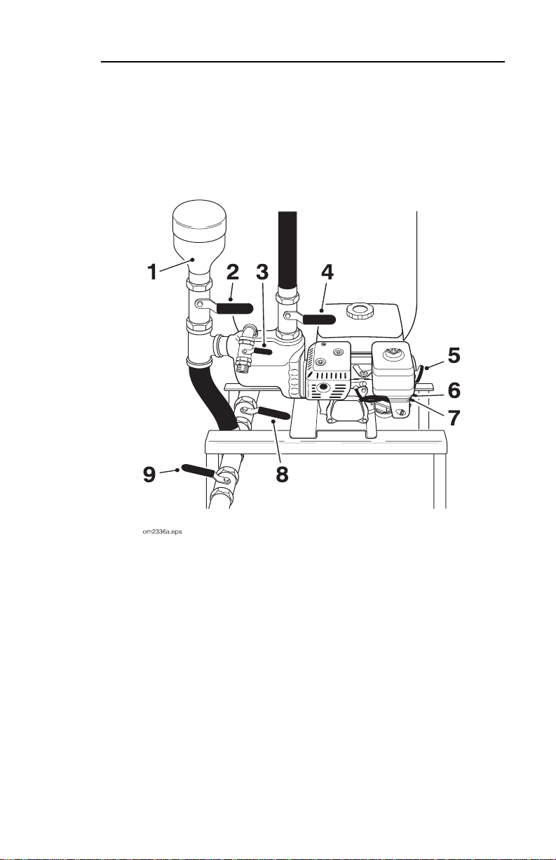
CONTROLS
1. Filler neck
2. Mixing valve
3. Discharge valve
4. Circulation valve
5. Rope start
6. Throttle
7. Choke
8. Tank discharge valve
9. Drain valve
Page 8

8
FT5 - CONTROLS
DESCRIPTIONS
DESCRIPTIONS
Filler Neck
Remove cap to add additives t o drilling fluid mixture. Replace cap
when finished.
Mixing Valve
Controls flow from filler neck to pump. Open only when pouring
additives into filler neck for mixing. Close when finished.
IMPORTANT:
Do not open valve unless pump is running.
Discharge Valve
Controls flow from FT5 to fluid pump on boring unit.
Circulation Valve
Controls flow from pump to tank. Open to circulate fluid between
pump and tank while mixing.
Page 9

FT5 - CONTROLS
Rope Start
Cranks engine for starting. Pull to start engine.
Throttle
Controls engine speed. Increasing engine speed also increases
pump flow.
Choke
Regulates air/fuel mixture in engine.
Tank Discharge Valve
This valve must be open while unit is running.
Open this valve and the drain valve to drain fluid from tank. If
drawing water into tank from an external source, open the drain
valv e and close this valve.
9
Drain Valve
Open this valve and tank discharge valve to drain fluid from tank.
If drawing water into tank from an external source, open this valve
and close tank discharge valve.
Page 10

10
FT5 - CONTROLS
Page 11

FT5 - SAFETY
11
SAFETY
For additional precautions and guidelines, consult boring unit
operator’ s manual before beginning bore. In addition, follow these
guidelines before operating any jobsite equipment:
• Do not operate any equipment unless you have completed
proper training and read the operator’ s manual.
• Wear personal protective equipment.
• Replace missing or damaged safety shields and safety signs.
• Do not operate unit where flammable gas is present.
• Use equipment carefully. Stop operation and invest igate
anything that does not look or feel right.
• Contact your Ditch Witch dealer if you have any question
about operation, maintenance, or equipment use.
Page 12

12
SAFETY ALERT CLASSIFICATIONS
FT5 - SAFETY
SAFETY ALERT CLASSIFICATIONS
These classifications and the icons defined on the following
pages work together to alert you to situations which could be
harmful to you, jobsite bystanders or your equipment. When you
see these words and icons in the book or on the machine,
carefully read and follow all instructions. YOUR SAFETY IS AT
STAKE.
Watch for the three safety alert levels:
CAUTION
. Learn what each level means.
DANGER, WARNING
and
indicates an imminently hazardous situation
which, if not avoided, will result in death or serious injury.
indicates a potentially hazardous situation which,
if not avoided, could result in death or serious injury.
indicates a potentially hazardous situation which,
if not avoided, may result in minor or moderate injury.
Watch for two other words:
NOTICE
can keep you from doing something that might damage
NOTICE
and
IMPORTANT
.
the machine or someone's property. It can also alert you against
unsafe practices.
IMPORT ANT
can help you do a better job or make your job
easier in s ome way.
Page 13

FT5 - SAFETY
SAFETY ALERTS AND NOTICES
SAFETY ALERTS AND NOTICES
Electric shock. Contacting electric
lines will cause death or serious injury. Know
location of lines and stay away.
Deadly gases. Lack of oxygen or
presence of gas will cause sickness or death.
Provide ventilation.
13
Fire or explosion possible. Fumes
could ignite and cause burns. No smoking, no
flame, no spark.
Page 14

14
FT5 - SAFETY
Improper handling or use of
chemicals may result in illness, injury, or
equipment damage. Follow instructions on labels
and in material safety data sheets (MSDS).
Fall possible. Slips or trips may
result in injury. Keep area clean.
Hot parts may cause burns. Do not
touch until cool.
Page 15

FT5 - LIFT
POINTS
Crushing weight could cause
death or serious injury. Use proper procedures
and equipment or stay away.
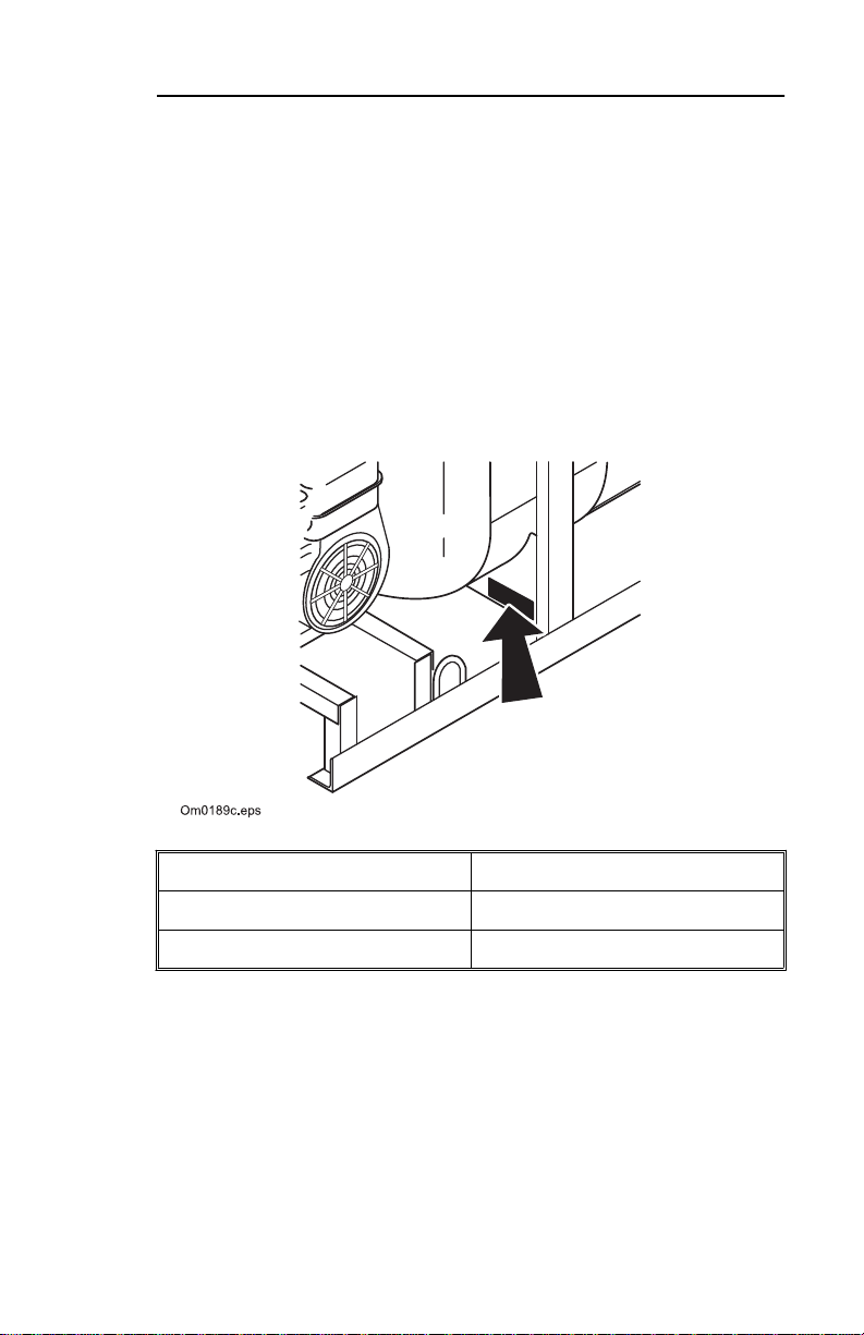
POINTS
Lifting Po int s
Lifting points are identified by lifting
decals. Lifting at any other point is
unsafe and can damage machinery.
15
LIFT
PROCEDURE
Lifting Skid
Lift skid by attaching chains to
designated lift points on sides of
skid.
IMPORTANT:
lifting.
Empty tank before
Page 16

16
FT5 - LIFT
PROCEDURE
Page 17

FT5 - SETUP
CHECK EQUIPMENT
17
SETUP
CHECK EQUIPMENT
Check the following before each day ’s work. Refer to
LUBRICATION AND MAINTENANCE
and locations.
• General appearance of equipment.
• Safety sign location and readability.
• All guard and shield locations. Replace if missing or worn.
• Condition of all wear items such as filters, hoses, and clamps.
• Drilling fluid hose s and electric cables for signs of leakage,
wear, or other damage.
• Engine crankcase oil level. Keep oil lev el at the highest line on
dipstick. Do not overf ill.
for additional information
• Fuel level. Fuel tank should be filled at the end of the day to
reduce condensation.
• All nuts and bolts. Tighten if necessary.
Page 18

18
FT5 - SETUP
SELECT DRILLING FLUID
SELECT DRILLING FLUID
For productive boring and equipment protection, use these
recommended Baroid
dealer.
®
products, available from your Ditch Witch
•Quik-Gel
•E-Z Mud
• Liqui-Trol
• Quik-Trol
• Bore-Gel
• Con-Det
•Poly-Bore
TM
dry powder bentonite (P/N 259-804)
TM
liquid polymer (P/N 259-805)
TM
liquid polymer suspension (P/N 259-808)
TM
dry powder polymer (P/N 259-809)
TM
drilling fluid (P/N 259-807)
TM
water-soluble cleaning solution (P/N 259-810)
TM
borehole stabilizing agent (P/N 259-820)
Guidelines
Match drillin g fluid to soil type. Although s pecif ic conditions at
each jobsite vary, use the following guidelines when selecting a
drilling fluid.
If soil is . . . use . . .
smooth, flowing sand bentonite + medium-chain polymer
coarse sand or light soil bentonite
heavy clay long-chain polymer
swelling c lay long-chain polymer
For recommended mixture to reach desired drilling fluid viscosity
or thickness, contact your Ditch Witch dealer.
Baroid and all Baroid products mentioned on this page are trademarks of Dresser Industries, Inc.
Page 19

FT5 - SETUP
SELECT DRILLING FLUID
Bentonite
19
IMPORTANT:
Before adding bentonite to drilling fluid, be sure
boring unit is equipped to use a bentonite mixture.
Bentonite is a dry powder. When properly mixed with water, it
cakes on bore walls, lubricating the bore, keeping it open, and
holding fluid in the bore.
Some things to remember when mixing bentonite:
• Use clean water free of salt, calcium, or excess ive chlorine.
• Use water with a pH level between 7.5 and 10.
• Do not use bentonite containing sand.
• Mix bentonite thoroughly or it will settle in tank.
• Do not mix bentonite to a funnel viscosity of over 50.
For information on measuring funnel viscosity, read “Measuring
Funnel Viscosity” in
OPERATION
.
Polymer
This drilling fluid additive provides excellent lubrication and
increase s vi sco s ity. In swelling clay, polymer c a n reduce swelling
that traps pipe in the bore.
There are two types of polymer:
• long-chain such as Baroid E-Z Mud.
• medium-chain such as Baroid Quik Trol.
Page 20

20
PLAN DRILLING FLUID REQUIREMENTS
FT5 - SETUP
Mixtures
Bentonite does not mix well in water containing polymer. To use
both, mix bentonite first, then add polymer.
Bore-Gel contains premixed bentonite, polymer, and soda ash.
Use 15 lb/100 gal (6.8 kg/378.5 L) in normal boring conditions
and up to 45 lb/100 gal (20.4 kg/378.5 L) in sand or gravel.
PLAN DRILLING FLUID REQUIREMENTS
1. Determine boring co nditions and choos e appropriate drilling
fluid mix.
2. Estimate amounts of supplies needed and check availability:
• drilling fluid
• water supply. If more water than can be carried with the
unit will be needed, arrange to transport additional water.
• bentonite and/or polymer
3. Check water quality.
• Using litmus paper, perform a pH test on water.
• If pH is below 5.0, add 1 cup (.25 L) soda ash per tank.
• Test and repeat until pH is between 7.5 and 10.
Page 21

FT5 - OPERATION
MIX DRILLING FLUID
21
OPERATION
Jobsite hazards
could cause death or serious injur y.
Use correct equipment and work
methods. Use and maintain proper
safety equipment.
NOTICES:
• Wear personal protective equipment including hard hat, safety
eye wear, and hearing protection.
• Do not wear jewelry or loose clothing.
MIX DRILLING FLUID
1. Fill fluid tank with water. Allow room for additives.
2. Open circulation valve and tank discharge valve.
3. Start engine and run at half throttle or higher.
4. Open mixing valve.
5. Remove filler neck cap and pour bentonite, polymer and other
additives into filler neck.
IMPORTANT:
sure boring unit is equipped to use a bentonite mixture.
6. Close mixing valve and replace filler nec k cap.
7. Mix well.
Before adding bentonite to drilling fluid, be
Page 22

22
FT5 - OPERATION
Measuring Funnel Viscosity
Fluid thickness is called viscosity. The higher the viscosity, the
harder the fluid is to push through the system.
To determine viscosit y, you will need a viscosity funnel and a
measuring cup, available from your Ditch Witch dealer.
1. Take a fresh sample from
the drilling fluid tank. The
sample must be more than 1
qt (.95 L).
2. Hold funnel over 1-qt (.95-L)
measuring cup and place a
finger over the outlet.
3. Pour test sample into top of
funnel. Fill to screen.
4. Remove finger and time
flow. Count the number of seconds it takes for 1 qt (.95 L) of
liquid to pass through the funnel. The number of seconds is
the viscosity.
See your Ditch Witch dealer for i nformation on matching viscosity
to soil type.
Page 23

FT5 - OPERATION
PUMP FLUID TO BORING UNIT
PUMP FLUID TO BORING UNIT
Electric shock. Contacting electric
lines will cause death or serious injury. Know
location of lines and stay away.
23
NOTICE:
If electrical strike occurs while fluid hose is connected
to boring unit, fluid system also will become electrif ied.
1. Connect hose from mixing pump to boring unit.
2. Open discharge valve and adjust engine throttle to give
desired flow rate to boring unit (approximately half throttle).
IMPORTANT:
If using bentonite in fluid mixture, leave
circulation valve approximately half open to allow continuous
mixing while boring.
A higher throttle setting is necessary if recirculating fluid
through the pump.
Page 24

24
FT5 - OPERATION
OPERATE IN COLD WEATHER
OPERATE IN COLD WEATHER
For successful operation in cold weather, follow these
procedures.
• Use pump to keep drilling fluid circulating at all times, ev en
when traveling to and from the jobsite.
• If possible, use all drilling fluid in tank before transporting the
unit away from the jobsite.
• To prepare unit for storage in cold weather, open all valves
and drain tank. Open drain valve on pump and drain pump.
Page 25

FT5 - LUBRICATION AND MAINTENANCE
LUBRICATION
LUBRICATION AND
MAINTENANCE
LUBRICATION
Check oil level in engine daily. Fill as needed with SAE 10 W40
engine oil. See manufact urer’s manual for lubrication schedule.
MAINTENANCE
Check filler neck daily. Filler neck should be clean and free of
obstructions.
25
Page 26

26
FT5 - LUBRICATION AND MAINTENANCE
TROUBLESHOOTING
Problem Possible solutions
TROUBLESHOOTING
poor drilling fluid mix
characteristics
Test water pH and treat if necessary (see
OPERATION
Residual polymer may be present in
tank. Drain tank and remix fluid, adding
bentonite first.
low yield properties Test water pH.
Try a different brand of drilling fluid
additive.
Add polymer to drilling fluid tank only
after bentonite has been yielded out.
for instructions).
Page 27

FT5 - SPECIFICATIONS
TROUBLESHOOTING
SPECIFICATIONS
Dimens ions U.S. Metric
L1, length (without hose and valve) 73 in 1.85 m
L2, leng th (with hose and valve) 84 in 2.13 m
W, width 32 in 0.81 m
H, height 53.5 i n 1.36 m
Weight with e mpty fluid tank 402 lb 182 kg
Weight with full fluid tank 2071 lb 939 kg
Fluid System U.S. Metric
Fluid t ank 200 gal 757 L
Fluid Capacities U.S. Metric
Fuel tank 1 gal 3.6 L
Engine oil with filter 0.63 qt 0.6 L
Engine U.S. Metric
Honda GX160, gasoline
Flywheel power @ 3600 rpm 5.4 hp 4 .0 kW
27
Page 28

28
FT5 - SPECIFICATIONS
 Loading...