


FM25
Operator’s
Manual
CMW
®
Issue 1.0
053-1187

FM25 Operator’s Manual Overview - 1
Overview
Chapter Contents
Serial Number Location . . . . . . . . . . . . . . . . . . . . . . 2
Intended Use . . . . . . . . . . . . . . . . . . . . . . . . . . . . . . 2
Unit Components . . . . . . . . . . . . . . . . . . . . . . . . . . . 3
About This Manual . . . . . . . . . . . . . . . . . . . . . . . . . . 3
• Bulleted Lists . . . . . . . . . . . . . . . . . . . . . . . . . . . . . . . . . . . . . . . . . . . . . .3
• Numbered Lists . . . . . . . . . . . . . . . . . . . . . . . . . . . . . . . . . . . . . . . . . . . .3
CMW
Overview - 2 FM25 Operator’s Manual
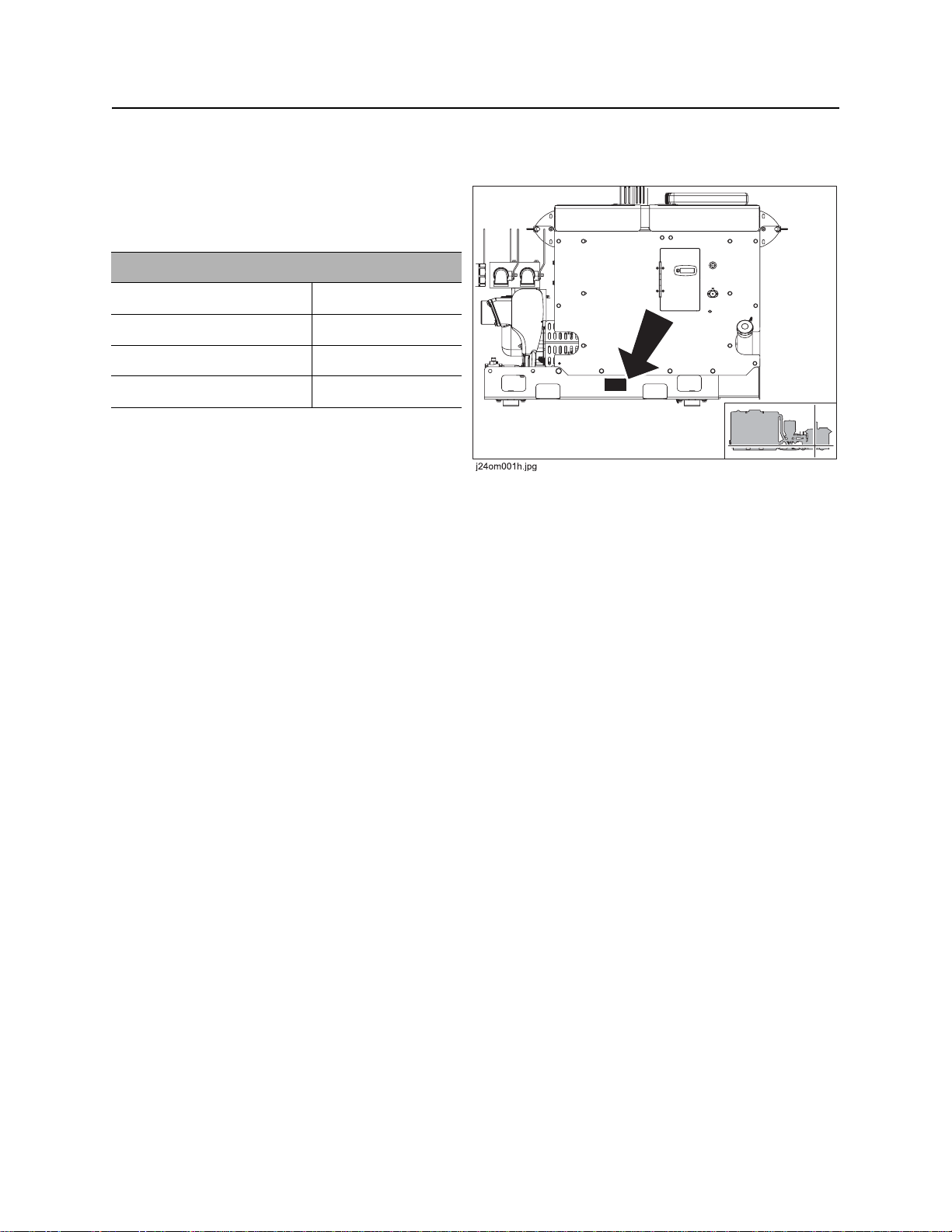
Serial Number Location
Serial Number Location
Record serial numbers and date of purchase in
spaces provided. Fluid unit serial number is
located as shown.
Item
date of manufacture
date of purchase
fluid unit serial number
engine serial number
Intended Use
The FM25 is a self-contained drilling fluid unit capable of mixing up to 1000 gal (3785 L) of drilling fluid per
tank and transferring fluid under pressure to the drilling unit. It is intended for operation in ambient
temperatures from 0° to 115°F (-18° to 46°C). Use in any other way is considered contrary to the intended
use.
The FM25 can be used with Ditch Witch drilling units and locating equipment. It should be operated,
serviced, and repaired only by persons familiar with its particular characteristics and acquainted with the
relevant safety procedures.
CMW
FM25 Operator’s Manual Overview - 3
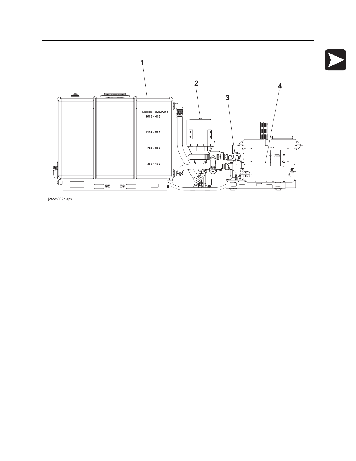
Unit Components
Unit Components
1. tank
2. hopper
3. pumps
4. power unit
About This Manual
This manual contains information for the proper use of this machine. See the beige Operation Overview
pages for basic operating procedures. Cross references such as “See page 50” will direct you to detailed
procedures.
Bulleted Lists
Bulleted lists provide helpful or important information or contain procedures that do not have to be
performed in a specific order.
Numbered Lists
Numbered lists contain illustration callouts or list steps that must be performed in order.
CMW

Overview - 4 FM25 Operator’s Manual
CMW

FM25 Operator’s Manual Foreword - 5
Foreword
This manual is an important part of your equipment. It provides safety information and operation
instructions to help you use and maintain your Ditch Witch equipment.
Read this manual before using your equipment. Keep it with the equipmen t at all times for future reference.
If you sell your equipment, be sure to give this manual to the new owner.
If you need a replacement copy, contact your Ditch Witch dealer. If you need assistance in locating a
dealer, visit our website at www.ditchwitch.com or write to the following address:
The Charles Machine Works, Inc.
Attn: Marketing Department
PO Box 66
Perry, OK 73077-0066
USA
The descriptions and specifications in this manual are subject to change without notice. The Charles
Machine Works, Inc. reserves the right to improve equipment. Some product improvements may have
taken place after this manual was publishe d. For the latest information on Ditch Witch equipment, see your
Ditch Witch dealer.
Thank you for buying and using Ditch Witch equipment.
CMW

Foreword - 6 FM25 Operator’s Manual
FM25
Operator’s Manual
Issue number 1.0/OM-10/07
Part number 053-1187
Copyright 2007
by The Charles Machine Works, Inc.
, Ditch Witch, CMW, AutoCrowd, Modularmatic, Jet Trac, Roto Witch, Subsite,
Fluid Miser, Perma-Soil, Power Pipe, Super Witch, Super Witch II, Pierce Airrow, The Underground, and
The Underground Authority Worldwide are registered trademarks of The Charles Machine Works, Inc.
Zahn and InterChange are pending trademarks of The Charles Machine Works, Inc.
CMW
FM25 Operator’s Manual Contents - 7
Content s
Overview
machine serial number, information about the type of work this machine is designed
to perform, basic machine components, and how to use this manual
Foreword
part number, revision level, and publication date of this manual, and factory contact
information
Safety
machine safety alerts and emergency procedures
Controls
machine controls, gauges, and indicators and how to use them
Operation Overview
an overview for completing a job with this machine: planning, setting up, handling
drilling fluid, and leaving the jobsite; with cross references to detailed procedures
Prepare
procedures for inspecting the jobsite and preparing the jobsite fo r work
Transport
procedures for lifting and hauling
1
5
9
17
25
29
33
Drilling Fluid Concepts
procedures for selecting fluid additives, determining fluid requirements, and
measuring viscosity
Complete the Job
procedures for rinsing and storing equipment
Service
service intervals and instructions for this machine including lubrication, replacement
of wear items, and basic maintenance
Specifications
machine specifications including weights, measurements, power ratings, and fluid
capacities
Support
the warranty policy for this machine, and procedures for obtaining warranty
consideration and training
Service Record
a record of major service performed on the machine
37
43
45
57
61
65
CMW

Contents - 8 FM25 Operator’s Manual
CMW

FM25 Operator’s Manual Safety - 9
Safety
Chapter Contents
Guidelines . . . . . . . . . . . . . . . . . . . . . . . . . . . . . . . . 10
Safety Alert Classifications . . . . . . . . . . . . . . . . . . 11
Safety Alerts . . . . . . . . . . . . . . . . . . . . . . . . . . . . . . 12
Emergency Procedures . . . . . . . . . . . . . . . . . . . . . 14
• Electric Strike Description. . . . . . . . . . . . . . . . . . . . . . . . . . . . . . . . . . . .14
• If an Electric Line is Damaged . . . . . . . . . . . . . . . . . . . . . . . . . . . . . . . .15
• If a Gas Line is Damaged . . . . . . . . . . . . . . . . . . . . . . . . . . . . . . . . . . . .16
• If a Fiber Optic Cable is Damaged . . . . . . . . . . . . . . . . . . . . . . . . . . . . .16
• If Machine Catches on Fire. . . . . . . . . . . . . . . . . . . . . . . . . . . . . . . . . . .16
CMW

Safety - 10 FM25 Operator’s Manual
Guidelines
Guidelines
Follow these guidelines before operating any jobsite equipment:
• Complete proper training and read operator’s manual before using equipment.
• Contact One-Call (888-258-0808) and any utility companies which do not subscribe to One-Call. Have
all underground pipes and cables located and marked before operating equipment. If you damage a
utility, contact utility company.
• Classify jobsite based on its hazards and use cor rect tools and machin ery, safety equipment, and work
methods for jobsite.
• Mark jobsite clearly and keep spectators away.
• Wear personal protective equipment.
• Review jobsite hazards, safety and emergency procedures, and individual responsibilities with all
personnel before work begins. Safety videos are available from your Ditch Witch dealer.
• Replace missing or damaged safety shields and safety signs.
• Use equipment carefully. Stop operation and investigate anything that does not look or feel right.
• Do not operate unit where flammable gas is present.
• Contact your Ditch Witch dealer if you have any question about operation, ma intenance, or equipment
use.
CMW

FM25 Operator’s Manual Safety - 11
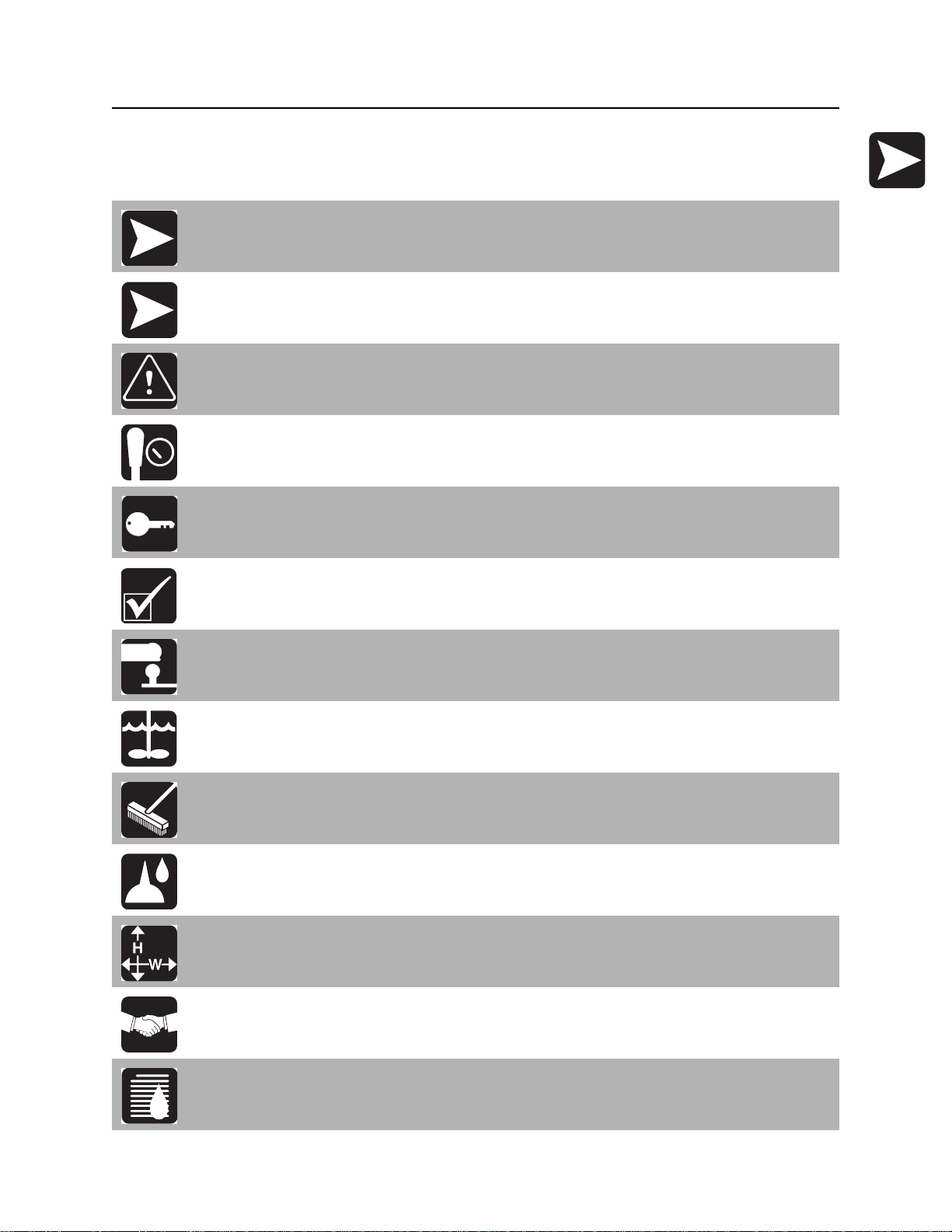
Safety Alert Classifications
Safety Alert Classifications
These classifications and the icons defined on the following pages work together to alert you to situations
which could be harmful to you, jobsite bystanders or your equipment. When you see these words and
icons in the book or on the machine, carefully read and follow all instructions. YOUR SAFETY IS AT
STAKE.
Watch for the three safety alert levels: DANGER, WARNING and CAUTION. Learn what each level
means.
indicates an imminently hazardous situation which, if not avoided, will result in death or
serious injury.
indicates a potentially hazardous situation which, if not avoided, could result in death or
serious injury.
indicates a potentially hazardous situation which, if not avoided, may result in minor or
moderate injury.
Watch for two other words: NOTICE and IMPORTANT.
NOTICE can keep you from doing something that might damage the machine or someone's property. It
can also alert you against unsafe practices.
IMPORTANT can help you do a better job or make your job easier in some way.
CMW
Safety - 12 FM25 Operator’s Manual
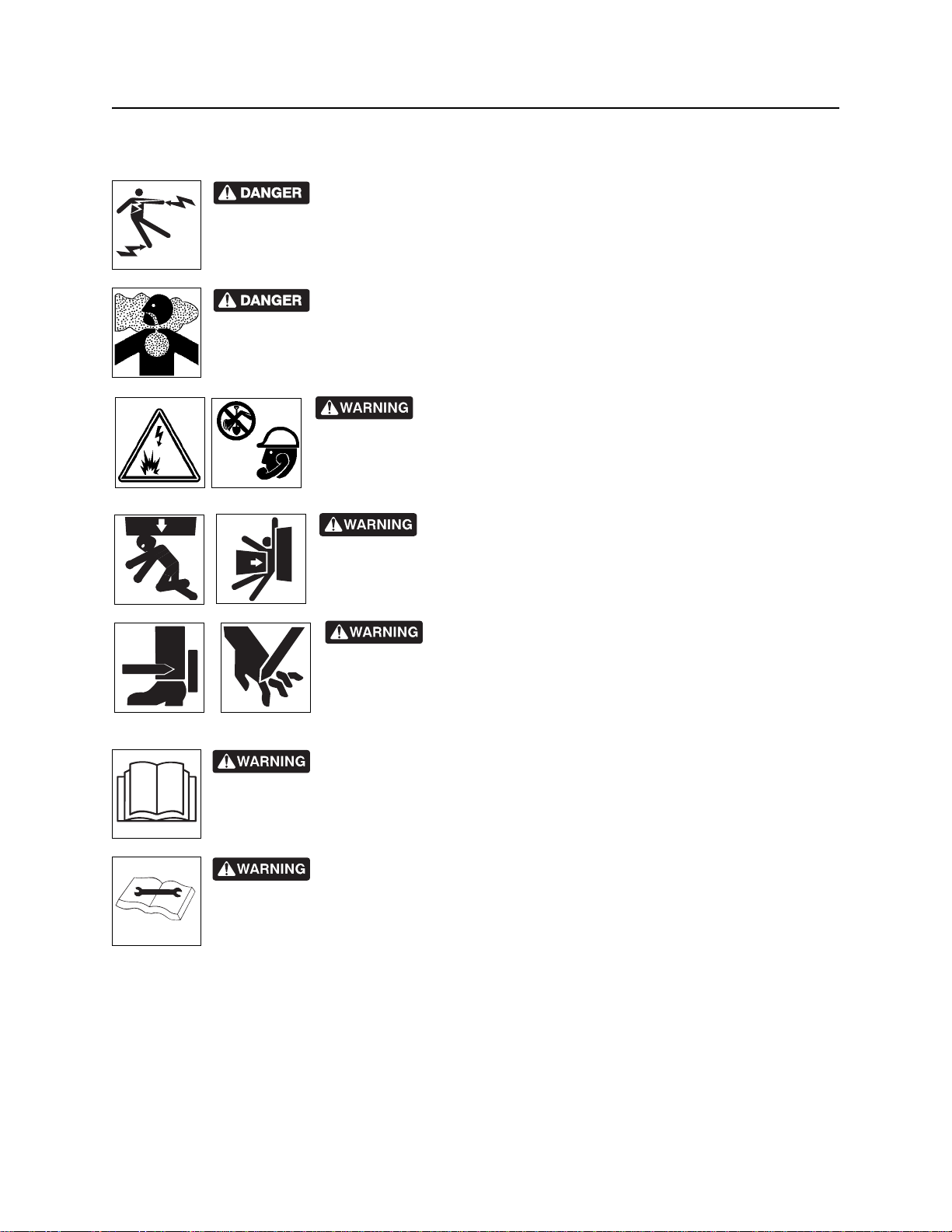
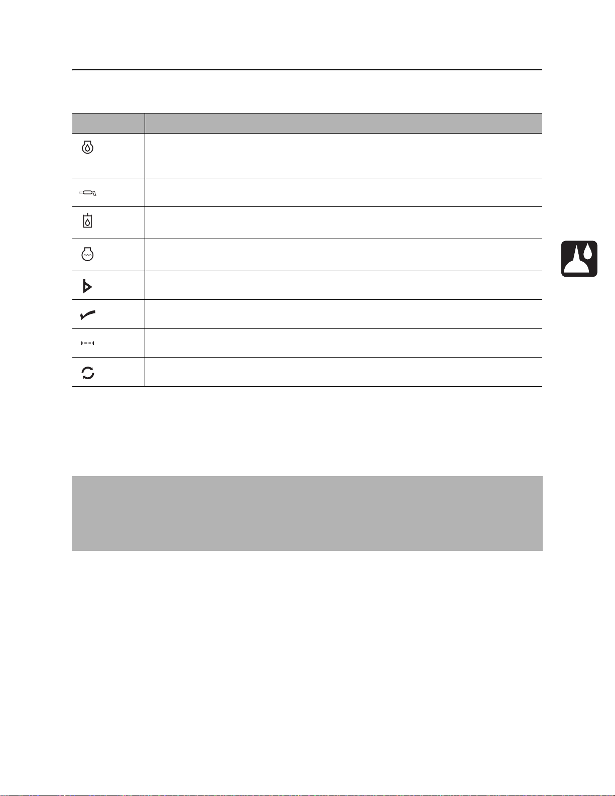
Safety Alerts
Safety Alerts
Electric shock. Contacting electric lines will cause death or serious injury.
Know location of lines and stay away.
Deadly gases. Lack of oxygen or presence of gas will cause sickness or
death. Provide ventilation.
Jobsite hazards could cause death or serious injury. Use
correct equipment and work methods. Use and maintain proper safety
equipment.
Crushing weight could cause death or seriou s injur y. Use
proper procedures and equipment or stay away.
Moving parts could cut off hand or foot. Stay away.
Incorrect procedures could result in death, injury, or property damage.
Learn to use equipment correctly.
Improper control function could cause death or serious injury. If control does
not work as described in instructions, stop machine and have it serviced.
CMW
FM25 Operator’s Manual Safety - 13
Safety Alerts
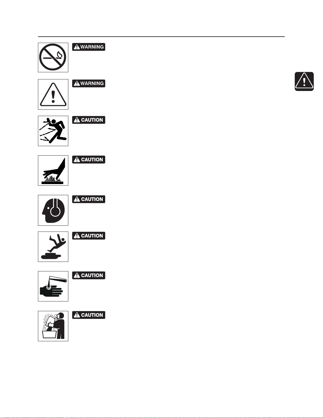
Fire or explosion possible. Fumes could ignite and cause burns. No
smoking, no flame, no spark.
Moving traffic - hazardous situation. Death or serious injury could result.
Avoid moving vehicles, wear high visibility clothing, post appropriate warning signs.
Flying objects may cause injury. Wear hard hat and safety glasses.
Hot parts may cause burns. Do not touch until cool.
Exposure to high noise levels may cause hearing loss. Wear hearing
protection.
Fall possible. Slips or trips may result in injury. Keep area clean.
Battery acid may cause burns. Avoid contact.
Improper handling or use of chemicals may result in illness, injury, or
equipment damage. Follow instructions on labels and in material safety data sheets
(MSDS).
CMW

Safety - 14 FM25 Operator’s Manual
Emergency Procedures
Emergency Procedures
Before operating any equipment, review emergency proc edures and check that all safety precau tions have
been taken.
EMERGENCY SHUTDOWN - Turn ignition switch to stop position or push remote e ngine stop button ( if
equipped).
Electric Strike Description
When working near electric cables, remember the following:
• Electricity follows all paths to ground, not just path of least resistance.
• Pipes, hoses, and cables will conduct electricity back to all equipment.
• Low voltage current can injure or kill. Almost one-third of work-related electrocutions result from
contact with less than 440 volts.
Most electric strikes are not noticeable, but indications of a strike include:
• power outage
•smoke
•explosion
• popping noises
• arcing electricity
If any of these occur, assume an electric strike has occurred.
CMW

FM25 Operator’s Manual Safety - 15
Emergency Procedures
If an Electric Line is Damaged
If you suspect an electric line has been damaged and you are on truck or trailer, DO NOT MOVE.
Remain on truck or trailer and take the following actions. The order and degree of action will depend on the
situation.
• Warn people nearby that an electric strike has occurred. Instruct them to leave the area and contact
utility.
• Contact utility company to shut off power.
• Do not return to area or allow anyone into area until given permission by utility company.
If you suspect an electric line has been damaged and you are off truck or trailer, DO NOT TOUCH
EQUIPMENT. Take the following actions. The order and degree of action will depend on the situation.
• LEAVE AREA.
• Contact utility company to shut off power.
• Do not return to area or allow anyone into area until given permission by utility company.
CMW

Safety - 16 FM25 Operator’s Manual
Emergency Procedures
If a Gas Line is Damaged
If you suspect a gas line has been damaged, take the following actions. The order and degree of action will
depend on the situation.
• Immediately shut off engine(s), if this can be done safely and quickly.
• Remove any ignition source(s), if this can be done safely and quickly.
• Warn others that a gas line has been cut and that they should leave the area.
• Leave jobsite as quickly as possible.
• Immediately call your local emergency phone number and utility company.
• If jobsite is along street, stop traffic from driving near jobsite.
• Do not return to jobsite until given permission by emergency personnel and utility company.
If a Fiber Optic Cable is Damaged
Do not look into cut ends of fiber optic or unidentified cable. Vision damage can occur.
If Machine Catches on Fire
Perform emergency shutdown procedure and then take the following actions. The order and degree of
action will depend on the situation.
• Immediately move battery disconnect switch (if equipped) to disconnect position.
• If fire is small and fire extinguisher is available, attempt to extinguish fire.
• If fire cannot be extinguished, leave area as quickly as possible and contact emergency personnel.
CMW

FM25 Operator’s Manual Controls - 17
Controls
Chapter Contents
Power Unit . . . . . . . . . . . . . . . . . . . . . . . . . . . . . . . 18
Mixing Unit . . . . . . . . . . . . . . . . . . . . . . . . . . . . . . . 23
CMW
Controls - 18 FM25 Operator’s Manual
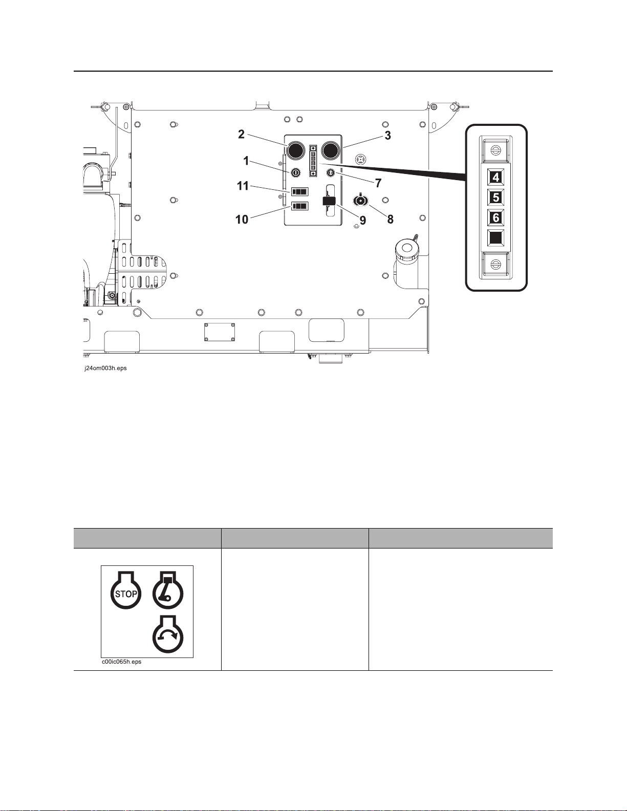
Power Unit
Power Unit
1. Ignition
2. Fuel gauge
3. Hourmeter
4. Engine oil pressure indicator
5. Coolant temperature indicator
6. Glow plug wait indicator
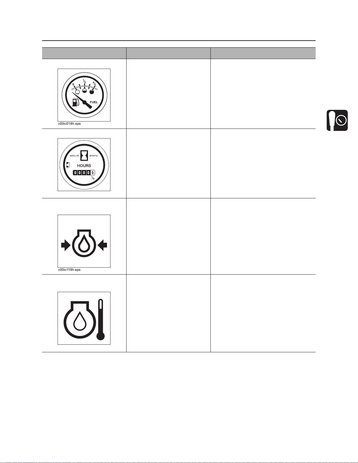
Item Description Notes
1. Ignition T o star t engine, insert key and
turn clockwise.
To stop engine, turn key
counterclockwise.
7. Glow plug button
8. Auxiliary outlet
9. Throttle
10. Pump 2 control
11. Pump 1 control
CMW
FM25 Operator’s Manual Controls - 19
Power Unit
Item Description Notes
2. Fuel gauge Displays fuel level in tank. Use #2 diesel fuel.
In temperatures below 40° F
(4° C), use #1 diesel fuel.
Tank holds 9.2 gal (35 L).
3. Hourmeter Displays engine operating
time.
c00ic259h.eps
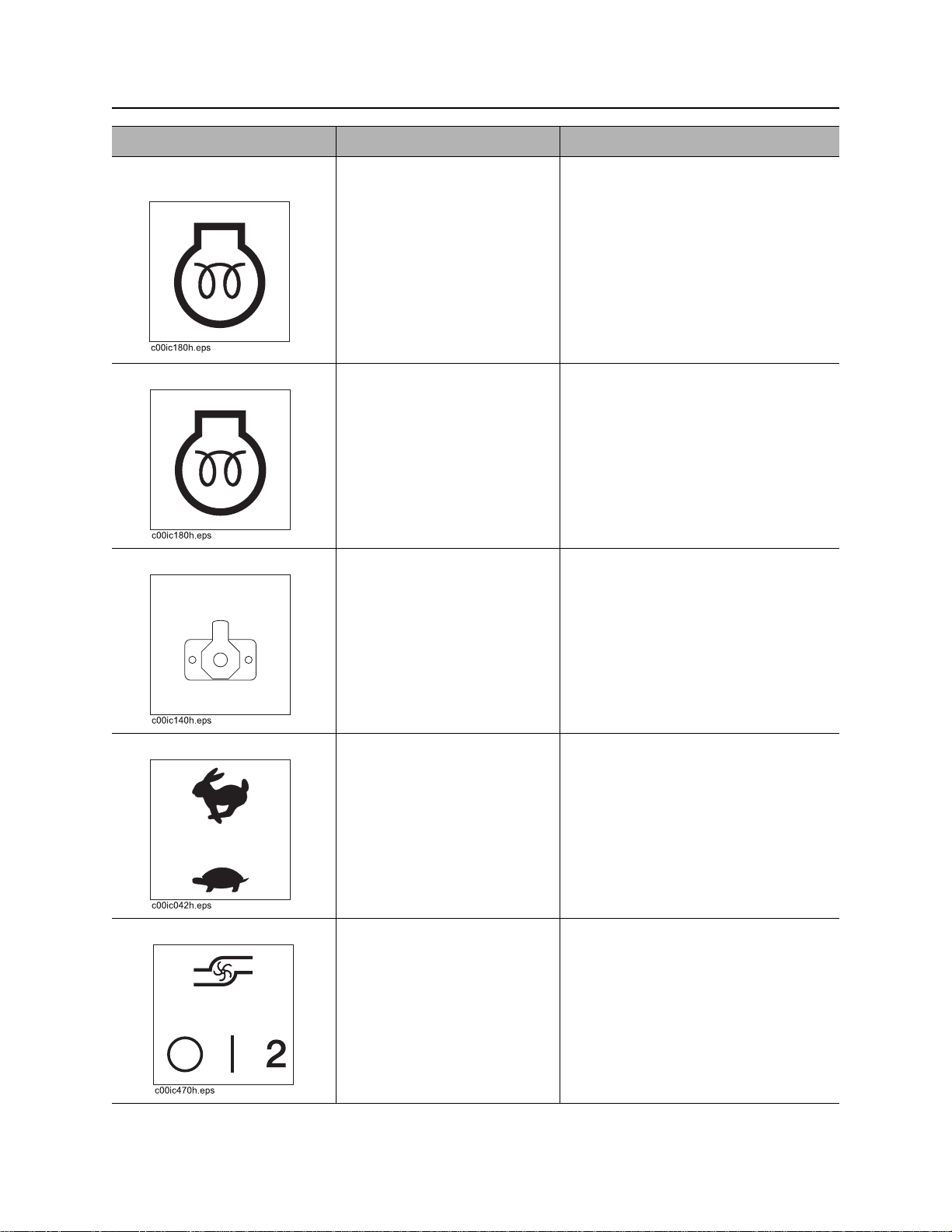
4. Engine oil pressure
indicator
Indicates engine oil pressure
is low.
Also lights briefly when
engine is started.
5. Coolant temperature
indicator
Lights when engine coolant
temperature is over 210°F
(100°C).
Hourmeter runs when ignition switch
is on.
Use these times to schedule service.
Engine will stop.
1. Check oil level.
2. Check for leaks before starting
engine.
• Allow engine to cool.
• Check coolant level.
c00ic232h.eps
CMW
Controls - 20 FM25 Operator’s Manual
Power Unit
Item Description Notes
6. Glow plug wait
indicator
7. Glow plug button To activate glow plugs, press. IMPORTANT: Wait until glow plug
8. Auxiliary outlet To operate work lights or
Lights when intake air preheater is operating.
Wait until light goes of f before
starting engine.
other 12V devices, plug into
outlet.
wait indicator goes off before starting
engine.
Outlet has power only when ignition
switch is on.
9. Throttle To increase engine speed,
move up.
To decrease engine speed,
move down.
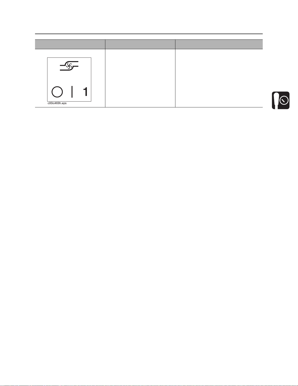
10. Pump 2 control To turn on pump, press right
side of switch.
To turn off pump, press left
side of switch.
CMW
FM25 Operator’s Manual Controls - 21
Power Unit
Item Description Notes
11. Pump 1 control To turn on pump, press right
side of switch.
To turn off pump, press left
side of switch.
CMW
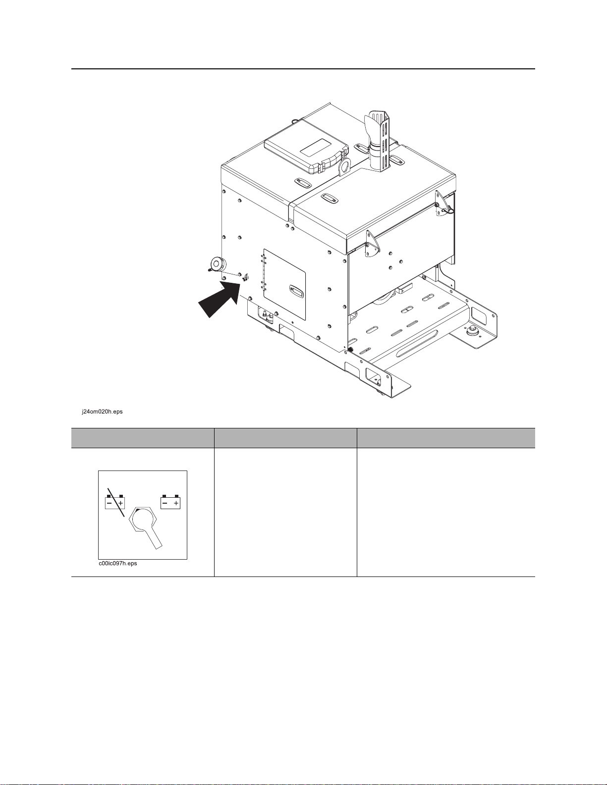
Controls - 22 FM25 Operator’s Manual
Item Description Notes
Battery disconnect switch To connect, move clockwise.
To disconnect, move
counterclockwise.
CMW
FM25 Operator’s Manual Controls - 23
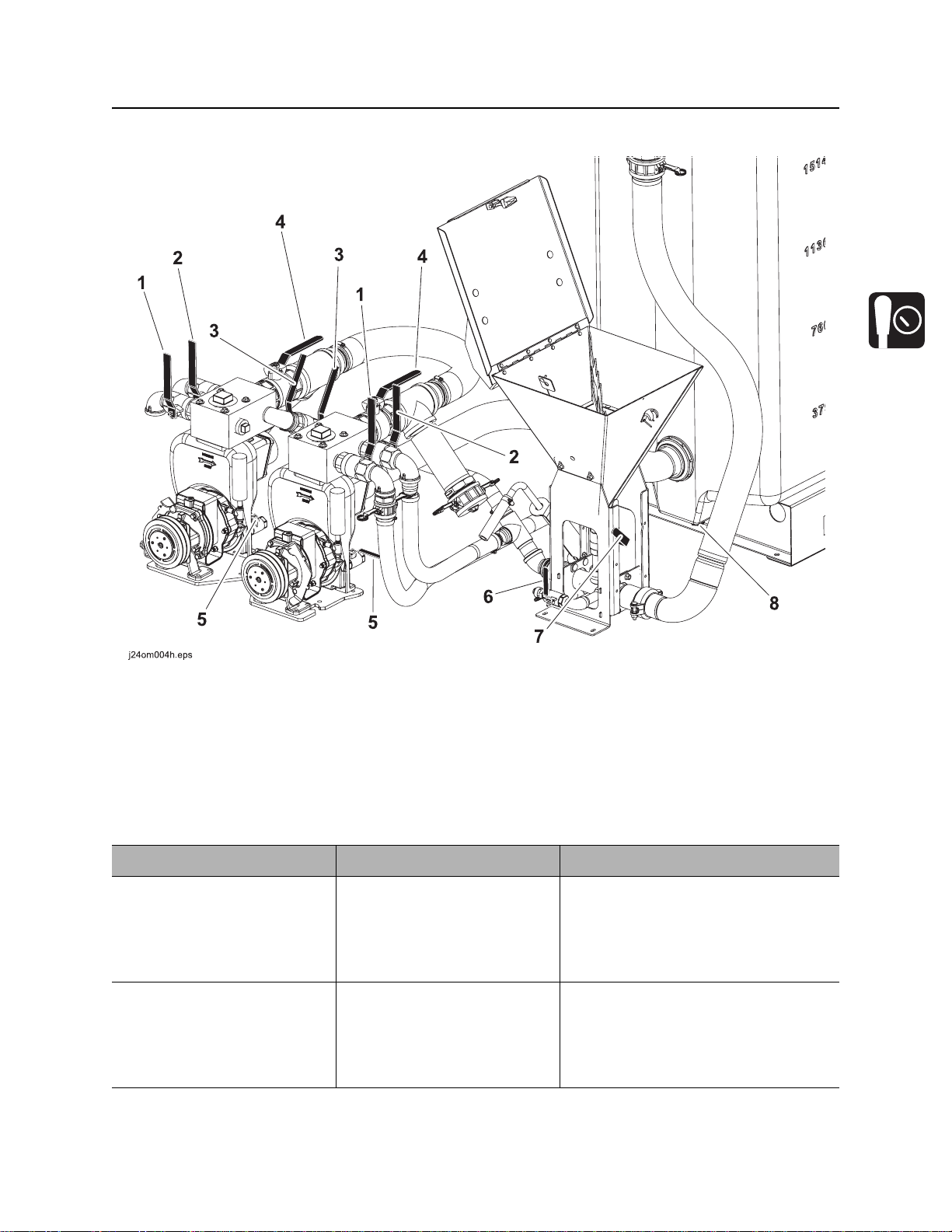
Mixing Unit
Mixing Unit
1. Mixing jet valve
2. Circulation valve
3. Transfer valve
4. Discharge valve
Item Description Notes
1. Mixing jet valve To allow flow from pump to
tank jets, open valve.
To stop flow from pump to
tank jets, close valve.
2. Circulation valve T o circulate fluid while mixing,
open valve.
To stop circulation, close
valve.
5. Pump drain valve
6. Liquid additive pickup valve
7. Hopper valve
8. Drain plug
See “Operation Overview” on page 25
for information about how to use this
control.
CMW

Controls - 24 FM25 Operator’s Manual
Mixing Unit
Item Description Notes
3. Transfer valve To allow flow from pump to
pump, open valve.
To stop flow from pump to
pump, turn off engine.
4. Discharge valve To allow flow from pump to
drilling unit, open valve.
To stop flow from pump to
drilling unit, close valve.
5. Pump drain valve To drain pump, open valve.
To use pump, close valve.
6. Liquid additive pickup
valve
7. Hopper valve To allow flow from hopper to
8. Tank drain plug To drain fluid from tank,
To allow liquid additives to
flow into mixture, open valve.
To stop flow of liquid
additives, close valve.
mixing venturi, open valve.
To stop flow from hopper to
mixing venturi, close valve.
remove plug.
Replace plug before refilling
tank.
IMPORTANT: Do not open valve
unless pump is running and mixing
venturi valve is open. Fluid could flow
back into hopper.
IMPORTANT:
• Open valve only when pouring
additives into hopper for mixing.
Close valve when finished.
• Do not open valve unless pump is
running and mixing venturi valve
is open. Fluid could flow back into
hopper.
CMW

FM25 Operator’s Manual Operation Overview - 25
Operation Overview
Chapter Contents
Planning . . . . . . . . . . . . . . . . . . . . . . . . . . . . . . . . . 26
Setting Up at Jobsite . . . . . . . . . . . . . . . . . . . . . . . 26
Mixing Fluid . . . . . . . . . . . . . . . . . . . . . . . . . . . . . . 27
Transferring Fluid . . . . . . . . . . . . . . . . . . . . . . . . . 28
Operating in Cold Weather . . . . . . . . . . . . . . . . . . 28
Leaving Jobsite . . . . . . . . . . . . . . . . . . . . . . . . . . . 28
CMW

Operation Overview - 26 FM25 Operator’s Manual
Planning
Planning
1. Gather information about jobsite (page 30).
2. Inspect jobsite (page 30).
3. Check supplies and prepare equipment (page 32).
Setting Up at Jobsite
1. Prepare jobsite (page 31).
2. Position fluid unit and connect to drilling unit. See drilling unit operator’s manual.
IMPORTANT: Leave unit hitched to towing vehicle or properly stabilized.
3. Block trailer wheels.
CMW

FM25 Operator’s Manual Operation Overview - 27
Mixing Fluid
Mixing Fluid
Jobsite hazards could cause death or serious injury. Use
correct equipment and work methods. Use and maintain proper safety
equipment.
NOTICE:
• Wear personal protective equipment including hard hat, safety eye wear, and hearing protection.
• Do not wear jewelry or loose clothing.
1. Verify that hopper throat is not plugged before mixing.
2. Fill fluid tank with water. Allow room for additives.
3. Open circulation valve and tank discharge valve.
4. Start engine and run at half throttle or higher.
5. Turn pump on.
6. Open hopper valve that corresponds to that pum p .
IMPORTANT: Do not open valve unless pump is running and mixing venturi va lve is open. Fluid
could flow back into hopper.
7. Open hopper lid and pour in bentonite. See page 39.
IMPORTANT: Before adding bentonite to drilling fluid, be sure drilling unit is equipped to use a
bentonite mixture.
8. Close hopper valve and close hopper lid.
9. Mix well.
10. Open liquid additives pickup valve to add liquid additives to mixture.
IMPORTANT: Run clean water through liquid additives pickup tube after each use.
CMW

Operation Overview - 28 FM25 Operator’s Manual
Transferring Fluid
Transferring Fluid
Electric shock. Contacting electric lines will cause death or serious injury.
Know location of lines and stay away.
NOTICE: If electrical strike occurs while fluid hose is connected to drilling unit, fluid system will also
become electrified.
1. Connect hose from mixing pump to drilling unit.
2. Open hopper and discharge valves.
IMPORTANT: If drilling fluid contains bentonite, leave circulation valve approximately half open
to allow continuous mixing while drilling.
3. Adjust engine throttle to maintain positive head at pump when unit is pum ping flu i d.
• Half throttle is recommended for most drilling situations.
• A higher throttle setting is required when recirculating fluid to maintain the mix in the tank.
Operating in Cold Weather
For successful operation in cold weather, follow these procedures.
• Use pump to keep drilling fluid circulating at all times, even during transport to and from the jobsite.
• If possible, use all drilling fluid in tank before transporting unit.
• For cold weather storage, drain tank and ensure all fluid system valves are open. Also open drain
valve on pump.
Leaving Jobsite
1. Rinse unit and tools (page 44).
2. Disconnect hoses (page 44).
CMW

FM25 Operator’s Manual Prepare - 29
Prep are
Chapter Contents
Gather Information . . . . . . . . . . . . . . . . . . . . . . . . . 30
• Arrange for Traffic Control . . . . . . . . . . . . . . . . . . . . . . . . . . . . . . . . . . .30
• Prepare for Working Near Existing Utilities . . . . . . . . . . . . . . . . . . . . . .30
• Plan for Emergency Services . . . . . . . . . . . . . . . . . . . . . . . . . . . . . . . . .30
Inspect Jobsite . . . . . . . . . . . . . . . . . . . . . . . . . . . . 30
Prepare Jobsite . . . . . . . . . . . . . . . . . . . . . . . . . . . 31
Check Supplies and Prepare Equipment . . . . . . . 32
• Assemble Accessories . . . . . . . . . . . . . . . . . . . . . . . . . . . . . . . . . . . . . .32
• Check Supplies . . . . . . . . . . . . . . . . . . . . . . . . . . . . . . . . . . . . . . . . . . .32
• Prepare Equipment . . . . . . . . . . . . . . . . . . . . . . . . . . . . . . . . . . . . . . . .32
CMW

Prepare - 30 FM25 Operator’s Manual
Gather Information
Gather Information
A successful job begins before the excavation. The first step in planning is reviewing information already
available about the job and jobsite.
Arrange for Traffic Control
If working near a road or other traffic area, contact local authorities about safety procedures and
regulations.
Prepare for Working Near Existing Utilities
If jobsite may contain electrical lines, wear protective boots and gloves meeting the following standards:
• Boots must have high tops and meet the electric hazard protection requirements of ANSI Z-41, 1991,
when tested at 14,000 volts. Tuck legs of pants completely inside boots.
• Gloves must have 17,000 AC maximum use voltage, according to ASTM spec ifica tio n D12 0-8 7.
If working around higher voltage, use gloves and boots with appropriately higher ratings.
Plan for Emergency Services
Have the telephone numbers for local emergency and medical facilities on hand. Check that you will have
access to a telephone.
Inspect Jobsite
• Follow U.S. Department of Labor regulations on excavating and trenching (Part 1926, Subpar t P) and
other similar regulations.
• Contact your local One-Call (811 in USA) or the One-Call referral number (888-258-0808 in USA and
Canada) to have underground utilities located before digging. Also contact any utilities that do not
participate in the One-Call service.
• Inspect jobsite and perimeter for evidence of underground hazards, such as:
– “Buried utility” notices
– Utility facilities without overhead lines
– Gas or water meters
– Junction boxes
– Drop boxes
– Light poles
– Manhole covers
– Sunken ground
• Mark location of all buried utilities and obstructions.
CMW

FM25 Operator’s Manual Prepare - 31
Prepare Jobsite
Prepare Jobsite
Jobsite hazards could cause death or serious injury. Use
correct equipment and work methods. Use and maintain proper safety
equipment.
NOTICE:
• If jobsite classification is in question or if the possibility of unmarked electric utilities exists, classify
jobsite as electric.
• Cutting high voltage cable can cause electrocution. Expose lines by hand before digging.
• All vegetation near operator’s station must be removed. Conta ct with trees, shrubs, or weeds during
electrical strike could result in electrocution.
CMW

Prepare - 32 FM25 Operator’s Manual
Check Supplies and Prepare Equipment
Check Supplies and Prepare Equipment
Assemble Accessories
Fire Extinguisher
If required, mount a fire extinguisher near the power unit but away from possible points of ignition. The fire
extinguisher should always be classified for both oil and electric fires. It should meet legal and regulatory
requirements.
Check Supplies
• water and additional hoses
•fuel
• drilling fluid additives, such as bentonite and polymer
Prepare Equipment
Fluid Levels
•fuel
• engine oil
Condition and Function
• filters (air, oil)
•tires
• hoses and valves
• couplers and fittings
• water tank
CMW

FM25 Operator’s Manual Transport - 33
Transport
Chapter Contents
Lift . . . . . . . . . . . . . . . . . . . . . . . . . . . . . . . . . . . . . . 34
• Points . . . . . . . . . . . . . . . . . . . . . . . . . . . . . . . . . . . . . . . . . . . . . . . . . . .34
• Procedure . . . . . . . . . . . . . . . . . . . . . . . . . . . . . . . . . . . . . . . . . . . . . . . .34
Haul . . . . . . . . . . . . . . . . . . . . . . . . . . . . . . . . . . . . . 35
CMW
Transport - 34 FM25 Operator’s Manual
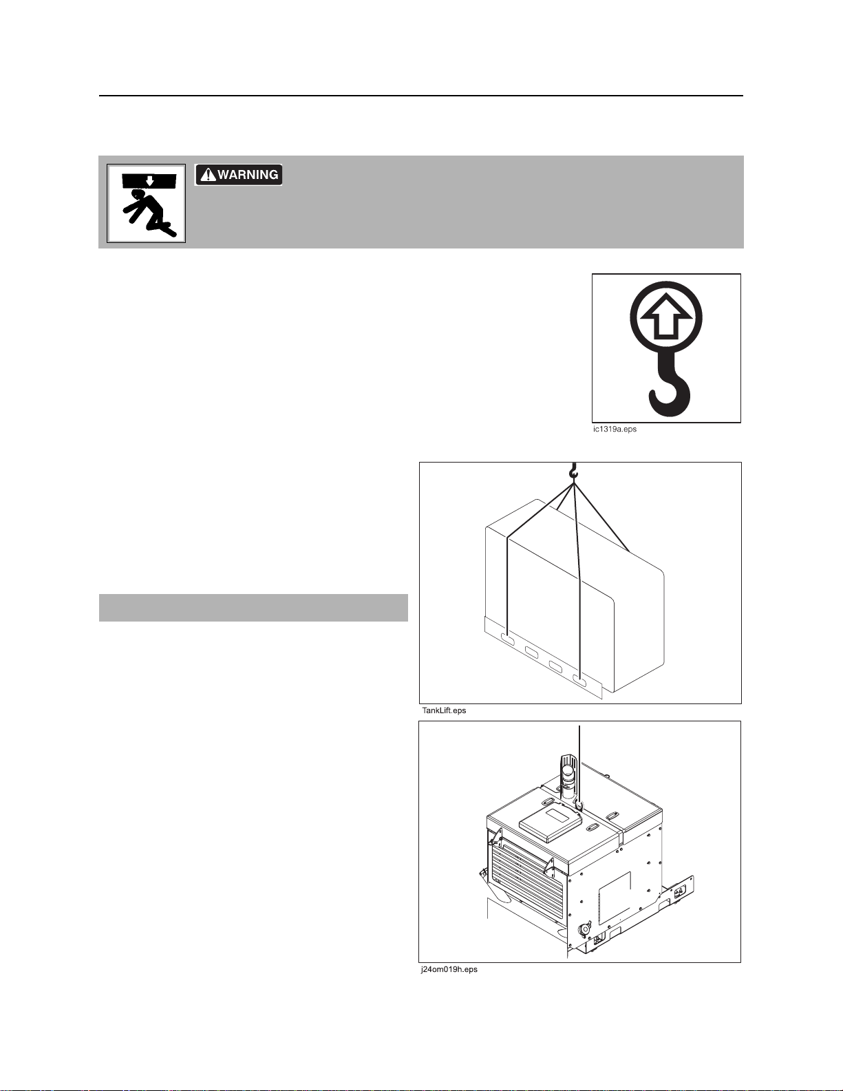
Lift
Lift
Crushing weight. If load falls or moves it could kill or crush you. Use
proper procedures and equipment or st ay away.
Points
Lifting points are identified by lifting decals. Lifting at other points is unsafe
and can damage machinery.
Procedure
Tank
Use crane capable of supporting the equipment's
size and weight. See “Specificatio ns” on page 57
or measure and weigh equipment before lifting. Lif t
mixing tank by attaching lif ting de vices at lift points
and joining at a common lift point.
IMPORTANT: Empty tank before lifting.
Power Unit
Use crane capable of supporting the equipment's
size and weight. See “Specificatio ns” on page 57
or measure and weigh equipment before lifting. Lif t
power unit by attaching lifting device at lift point.
CMW

FM25 Operator’s Manual Transport - 35
Haul
Haul
IMPORTANT: For trailer information, see the trailer manufacturer’s manual.
CMW

Transport - 36 FM25 Operator’s Manual
Haul
CMW

FM25 Operator’s Manual Drilling Fluid Concepts - 37
Drilling Fluid Concepts
Chapter Contents
Recommended Products . . . . . . . . . . . . . . . . . . . . 38
Guidelines . . . . . . . . . . . . . . . . . . . . . . . . . . . . . . . . 38
Polymer . . . . . . . . . . . . . . . . . . . . . . . . . . . . . . . . . . 39
Bentonite . . . . . . . . . . . . . . . . . . . . . . . . . . . . . . . . 39
Mixtures . . . . . . . . . . . . . . . . . . . . . . . . . . . . . . . . . 40
• General mixing order . . . . . . . . . . . . . . . . . . . . . . . . . . . . . . . . . . . . . . .40
• Basic fluid recipes . . . . . . . . . . . . . . . . . . . . . . . . . . . . . . . . . . . . . . . . .41
Drilling Fluid Requirements. . . . . . . . . . . . . . . . . . 42
Funnel Viscosity . . . . . . . . . . . . . . . . . . . . . . . . . . 42
CMW

Drilling Fluid Concepts - 38 FM25 Operator’s Manual
Recommended Products
Recommended Products
For productive drilling and equipment protection, use these recommended Baroid® products, available
from your Ditch Witch dealer.
• Soda ash
• Quik-Gel™ dry powder bentonite (p/n 259-804)
• E-Z Mud™ liquid polymer (p/n 259-805)
• Liqui-Trol™ liquid polymer suspension (p/n 259-808)
• Quik-Trol™ dr y powder polymer (p/n 259-809)
• Bore-Gel™ drilling fluid (p/n 259-807)
• Con-Det™ water-soluble cleaning solution (p/n 259-810)
Guidelines
Match drilling fluid to soil type. This chart is meant as a guideline only . See your local Ditch Witch dealer for
soil conditions and drilling fluid recommendations for your area. Also see our interactive Drilling Fluid
Formulator at www.ditchwitch.com.
Soil type Drilling fluid recommendation
smooth, flowing sand bentonite or Bore-Gel + medium chain polymer
coarse sand or light soil bentonite or Bore-Gel
heavy clay long chain polymer + Con-Det
swelling clay long chain polymer + Con-Det
rock Bore-Gel
CMW

FM25 Operator’s Manual Drilling Fluid Concepts - 39
Polymer
Polymer
This drilling fluid additive provides excellent lubrication and increases viscosity in average soils and heavy
clay. In swelling clay, polymer can reduce swelling that traps pipe in the bore.
There are two types of polymer:
• long chain such as Baroid EZ-Mud
• medium chain such as Baroid Quik-Trol
Bentonite
Bentonite is a dry powder. When properly mixed with water, it forms a thin cake on bore walls, lubricating
the bore, keeping it open, and holding fluid in the bore.
Some things to remember when mixing bentonite:
• Use clean water free of salt, calcium, or excessive chlorine.
• Use water with pH level between 9 and 10.
• Use water with hardness of less than 120 ppm.
• Do not use bentonite containing sand.
• Mix bentonite thoroughly or it will settle in tank.
• Do not mix bentonite to a funnel viscosity of over 50.
For information on measuring funnel viscosity, see “Funnel Viscosity” on page 42.
CMW

Drilling Fluid Concepts - 40 FM25 Operator’s Manual
Mixtures
Mixtures
NOTICE: Bentonite does not mix well in water containing polymer. To use both, mix bentonite first, then
add polymer.
• If chemicals are added in the wrong order, they will not mix properly and will form clumps.
• If tank contains bentonite/polymer mix and more drilling fluid is needed, completely empty tank and
start with fresh water before mixing another batch.
General mixing order
1. Soda ash
2. Bentonite
3. Polymer
4. Con-Det
Bore-Gel contains premixed bentonite, polymer, and soda ash. Follow guidelines below to ensure proper
drilling fluid viscosity for expected drilling conditions.
Conditions Amount to Use
normal drilling 15 lb/100 gal 7 kg/380 L
sand or gravel up to 45 lb/100 gal up to 21 kg/380 L
rock up to 50 lb/100 gal up to 23 kg/380
CMW

FM25 Operator’s Manual Drilling Fluid Concepts - 41
Mixtures
Basic Fluid Recipes
Soil type Mixture/100 gal (378 L) of water Notes
fine sand 35 lb (16 kg) Bore-Gel
coarse sand 35 lb (16 kg) Bore-Gel
.5 lb (225 g) No-Sag
fine sand below water
table
coarse sand below
water table
gravel 50 lb (23 kg) Bore-Gel
cobble 50 lb (23 kg) Bore-Gel
sand, gravel, clay or
shale
clay .5 lb (225 g) Poly Bore
swelling/sticky clay .75 - 1 lb (340-450 g) Poly Bore
40 lb (18 kg) Bore-Gel
.75 lb (340 g) Quik-Trol
40 lb (18 kg) Bore-Gel
.75 lb (340 g) Quik-Trol
.75 lb (340 g) No-Sag
.75 lb (340 g) Quik-Trol
.75 lb (340 g) No-Sag
.75 lb (340 g) Quik-Trol
.75 lb (340 g) No-Sag
35 - 40 lb (16-18 kg) Bore-Gel
.5 pt (235 mL) EZ-Mud
.5 gal (2 L) Con-Det
.5 gal (2 L) Con-Det
.5 - 1 gal (2-4 L) Con-Det
Add .5 lb (225 g) of Quik-Trol for
additional filtrate control
Add .5 - 1 gal (2-4 L) of Dinomul in high
torque situations
Add .5 - 1 gal (2-4 L) of Dinomul in high
torque situations
Add .5 lb (225 g) of Barolift to reduce loss
of returns
Add .5 lb (225 g) of Barolift to reduce loss
of returns
Vary mixture according to percentage of
sand and clay
Flow rate should be 3-5 parts fluid to 1
part soil. May use .25 - .5 gal (1-2 L) of
Penetrol instead of Con-Det
Flow rate should be 3-5 parts fluid to 1
part soil. May use .25 - .5 gal (1-2 L) of
Penetrol instead of Con-Det
solid rock (shale) 40 lb (18 kg) Bore-Gel Use .5 pt (235 mL) of No Sag for large
diameter or longer bores
solid rock (other than
shale)
rock/clay mixture 40 - 50 lb (18-23 kg) Bore-Gel
rock/sand mixture 40 - 50 lb (18-23 kg) Bore-Gel Use .5 pt (235 mL) of No Sag for large
fractured rock 50 lb (23 kg) Bore-Gel
40 - 50 lb (18-23 kg) Bore-Gel Use .5 pt (235 mL) of EZ-Mud in reactive
shales
.5 pt (235 mL) EZ-Mud
diameter or longer bores
Use .5 lb (225 g) of Barolift to reduce fluid
.5 - 1lb (225-450 g) No-Sag
loss to formation
CMW
Drilling Fluid Concepts - 42 FM25 Operator’s Manual
Drilling Fluid Requirements
Drilling Fluid Requirements
1. Determine drilling conditions and choose appropriate drilling fluid mix.
2. Estimate amount of supplies needed and check availability.
• Drilling fluid
• Water supply. If more water than can be carried with the unit will be needed, arrange to transport
additional water.
• Bentonite and/or polymer
3. Check water quality.
• Use meter or pH test strips to test pH of water. If pH is below 9.0, add 1 lb (454 g) soda ash per
tank. Test and repeat until pH is between 9 and 10.
• Check water hardness using hardness test strips. Treat with soda ash if hardness exceeds 125
ppm.
Funnel Viscosity
Viscosity is the measure of internal resistance of a fluid to flow; the greater the resistance, the higher the
viscosity. Viscosity of drilling fluids must be controlled.
To determine viscosity, you will need a Marsh funnel (p/n 259-267) and a measuring cup, available from
your Ditch Witch dealer.
IMPORTANT: Make sure Marsh funnel is clean and free of obstruction and that you have a stopwatch
available for timing the viscosity.
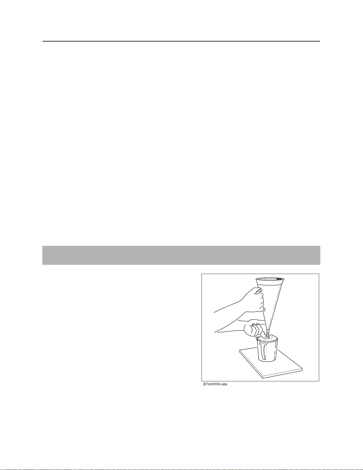
1. Using wash hose and a clean container, take a fresh
sample of drilling fluid. The sample must be at least
1.5 qt (1.4 L).
2. With finger over bottom of funnel, fill with fluid from
the container through the screen until fluid reaches
the bottom of the screen.
3. Move funnel over 1 qt (.95 L) container.
4. Remove finger from bottom of funnel and use the
stopwatch to count the number of seconds it t akes for
1 qt (.95 L) of fluid to pass through the funnel. The
number of seconds is the viscosity.
5. Thoroughly rinse measuring cup and Marsh funnel.
CMW

FM25 Operator’s Manual Complete the Job - 43
Complete the Job
Chapter Contents
Rinse Equipment . . . . . . . . . . . . . . . . . . . . . . . . . . 44
Disconnect . . . . . . . . . . . . . . . . . . . . . . . . . . . . . . . 44
CMW

Complete the Job - 44 FM25 Operator’s Manual
Rinse Equipment
Rinse Equipment
Spray water onto equipment to remove dirt and mud.
Disconnect
Disconnect and store hoses and cables.
CMW

FM25 Operator’s Manual Service - 45
Service
Chapter Contents
Service Precautions . . . . . . . . . . . . . . . . . . . . . . . . 46
• Welding Precaution . . . . . . . . . . . . . . . . . . . . . . . . . . . . . . . . . . . . . . . .46
• Washing Precaution . . . . . . . . . . . . . . . . . . . . . . . . . . . . . . . . . . . . . . . .46
Recommended Lubricants/Service Key . . . . . . . . 47
• Engine Oil Temper atur e Char t . . . . . . . . . . . . . . . . . . . . . . . . . . . . . . . .48
• Approved Coolant . . . . . . . . . . . . . . . . . . . . . . . . . . . . . . . . . . . . . . . . .48
10 Hour . . . . . . . . . . . . . . . . . . . . . . . . . . . . . . . . . . 49
50 Hour . . . . . . . . . . . . . . . . . . . . . . . . . . . . . . . . . . 50
100 Hour . . . . . . . . . . . . . . . . . . . . . . . . . . . . . . . . . 52
150 Hour . . . . . . . . . . . . . . . . . . . . . . . . . . . . . . . . . 53
250 Hour . . . . . . . . . . . . . . . . . . . . . . . . . . . . . . . . . 53
500 Hour . . . . . . . . . . . . . . . . . . . . . . . . . . . . . . . . . 54
2000 Hour . . . . . . . . . . . . . . . . . . . . . . . . . . . . . . . . 55
As Needed . . . . . . . . . . . . . . . . . . . . . . . . . . . . . . . 56
CMW

Service - 46 FM25 Operator’s Manual
Service Precautions
Service Precautions
Incorrect procedures could result in death, injury, or property damage.
Learn to use equipment correctly.
NOTICES:
• Unless otherwise instructed, all service should be performed with engine off.
• Refer to engine manufacturer’s manual for engine maintenance instructions.
Welding Precaution
NOTICE: Welding can damage electronics.
• Welding currents can damage electronic components. Connect welder ground close to welding
point and make sure no electronic comp on en ts are in the gro u nd path. .
• Disconnect battery at battery disconnect switch before welding to prevent damage to battery.
• Do not turn off battery disconnect switch with engine running, or alternator and other electronic
devices may be damaged.
Washing Precaution
NOTICE: W ater can damage electronics. When clean ing equipment, do not spray electrical component s
with water.
CMW
FM25 Operator’s Manual Service - 47
Recommended Lubricants/Service Key
Recommended Lubricants/Service Key
Item Description
DEO Diesel engine oil meeting or exceeding CH-4 per the API service classification or E5
per the European Automobile Manufacturer’s Association (ACEA) and SAE viscosity
recommended by engine manufacturer (SAE 10W30)
MPG Multipurpose grease meeting ASTM D217 and NLGI 5
THF Tractor hydraulic fluid, similar to Phillips 66 HG, Mobilfluid 423, Chevron Tractor
Hydraulic Fluid, Texaco TDH Oil, or equivalent
DEAC Diesel engine antifreeze/coolant meeting ASTM D5345 (prediluted) or D4985
(concentrate)
Check level of fluid or lubricant
Check condition
Filter
Change, replace, adjust, service or test
Proper lubrication and maintenance protects Ditch Witch equipment from damage and failure. Service
intervals listed are for minimum requirements. In ex treme conditions, service machine more frequently.
Use only recommended lubricants. Fill to capacities listed in “Fluid Capacities” on page 92.
For more information on engine lubrication and maintenance, see your Kubota
NOTICE:
• Use only genuine Ditch Witch parts, filters, approved lubricants, TJC, and approved coolants to
maintain warranty.
• Use the “Service Record” on page 65 to record all required service to your machine.
®
engine manual.
CMW
Service - 48 FM25 Operator’s Manual
Recommended Lubricants/Service Key
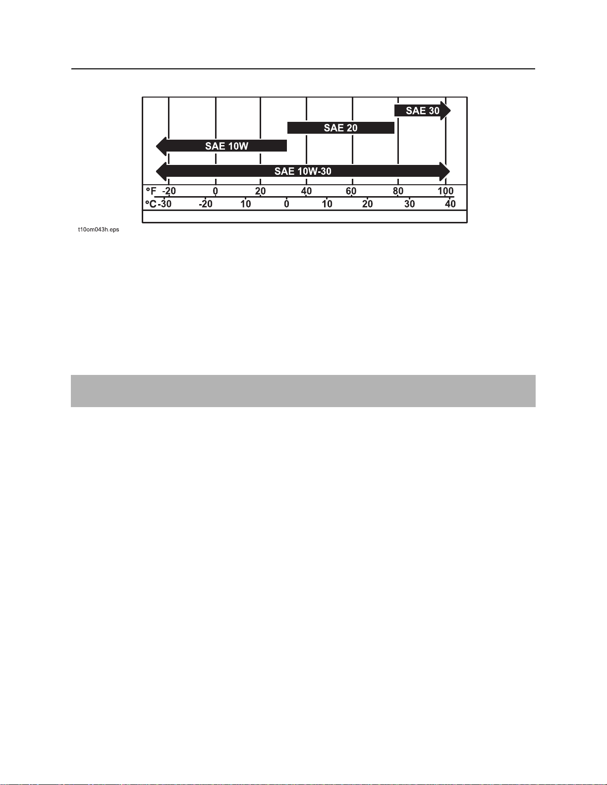
Engine Oil Temperature Chart
Temperature range anticipated before next oil change
Approved Coolant
Any coolant is approved for use with this unit. However, it was filled with John Deere Cool-Gard coolant
before shipment from factory. Add only Cool-Gard (p/n 255-006) or any fully-formulated, ethylene glycol
based, low-silicate, heavy-duty diesel engine coolant meeting ASTM specification D5345 (prediluted) or
D4985 (concentrate). Before using any other kind of coolant, completely flush radiator.
NOTICE: Do not mix heavy-duty diesel engine coolant and automotive-type coolant. This will lead
coolant breakdown and engine damage.
CMW
FM25 Operator’s Manual Service - 49
10 Hour
10 Hour
Location Task Notes
Check coolant level DEAC
Check engine oil level DEO
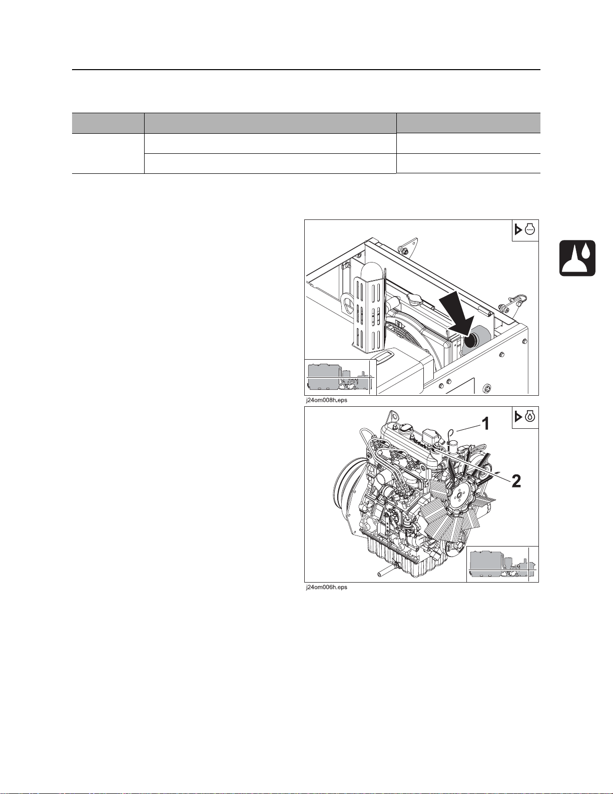
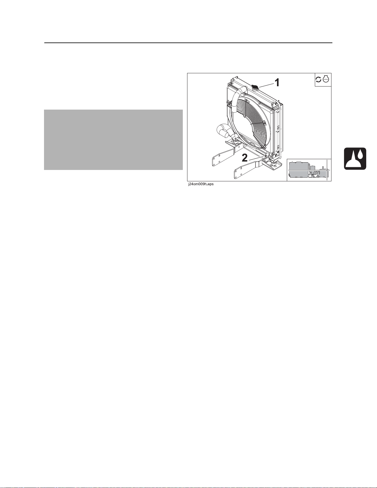
Check Coolant Level
Check coolant level every 10 hours. Add coolant at
cap (shown) as needed to maintain level between
LOW and FULL on overflow tank.
Check Engine Oil Level
Check engine oil level at dipstick (1) every 10
hours. Add DEO at fill (2) as needed to maintain oil
level at highest line on dipstick.
CMW
Service - 50 FM25 Operator’s Manual
50 Hour
50 Hour
Location Task Notes
Check air filter
Check battery
Change engine oil and filter Initial, DEO
Lube pump
Check radiator
Check Air Filter
Check air filter every 50 hours. Replace as
needed.
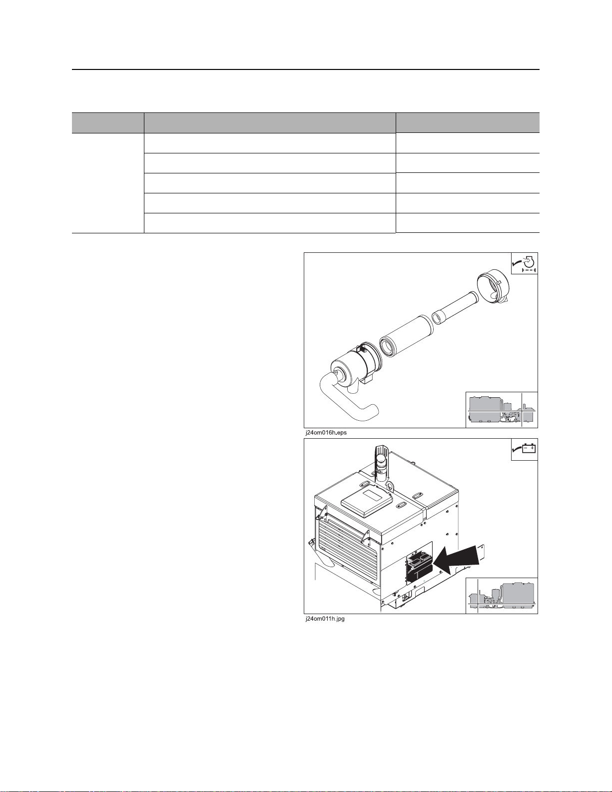
Check Battery
Check battery connections for corrosion every 50
hours. Keep connections clean and tight. Batteries
supplied by the factory are maintenance fr ee .
Service replacement batteries according to
manufacturer’s instructions.
CMW
FM25 Operator’s Manual Service - 51
50 Hour
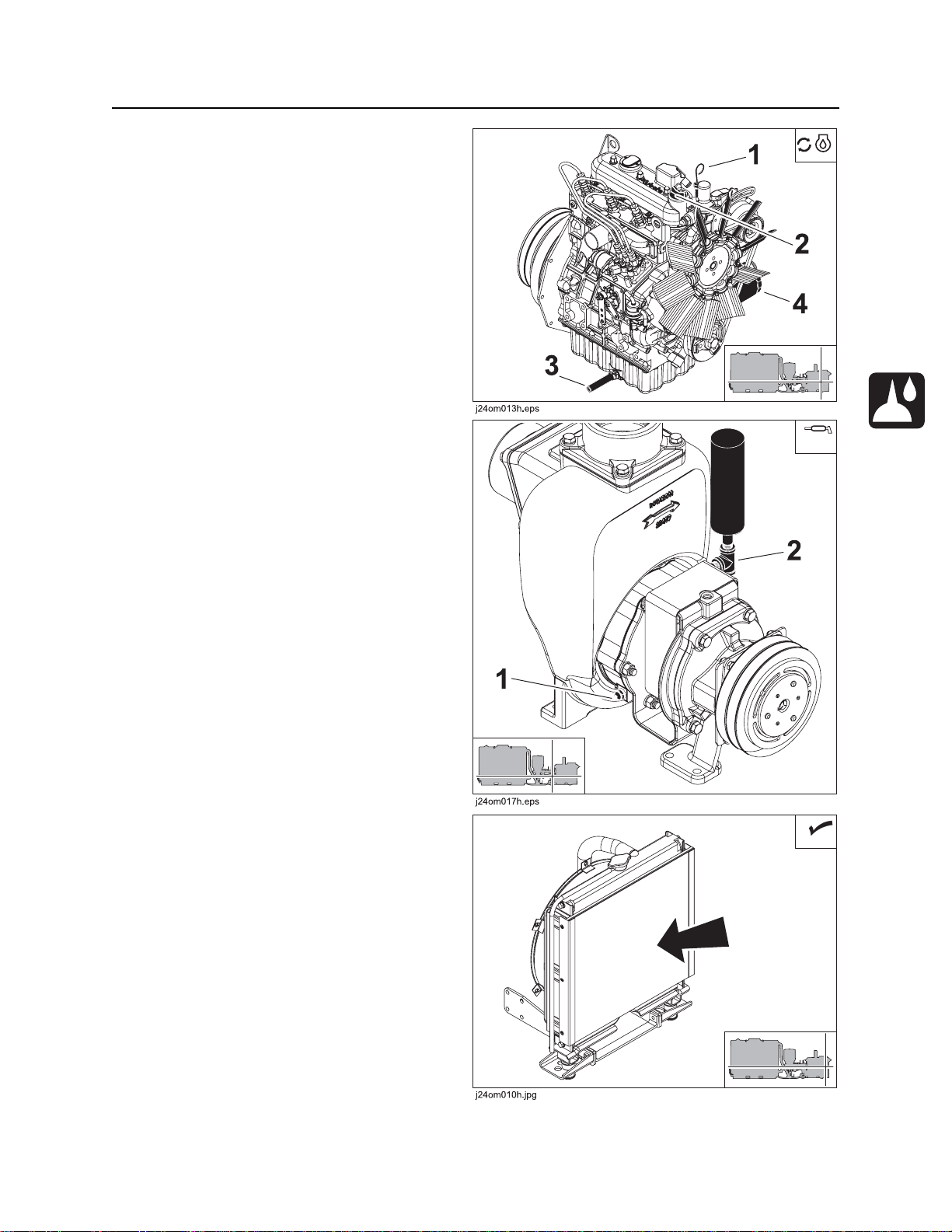
Change Engine Oil and Filter (Initial)
Change engine oil after 50 hours while oil is warn
and with unit parked on level ground.
1. Open drain (3).
2. Replace filter (4).
3. Close drain.
4. Add DEO at fill (2) until oil level is at highest
line on dipstick (1).
Lube Pump
Lube zerk (2) with MPG every 50 hours. Grease
cavity is full when grease escapes from grease
cylinder relief valve (1).
Check Radiator
Check radiator for dirt, grass, and other foreign
matter every 50 hours. Clean out with compressed
air or spray wash if required. Be careful not to
damage fins with high-pressure air or water . Check
more often if operating in dusty or grassy
conditions.
CMW

Service - 52 FM25 Operator’s Manual
100 Hour
100 Hour
Location Task Notes
Change fuel filters
Check fan belt tension
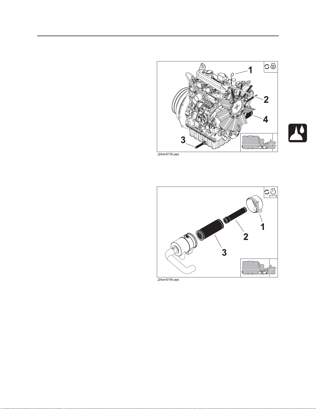
Change Fuel Filters
Change fuel filter (1) and inline fuel filter (2) every
100 hours.
1. Remove filters.
2. Fill new filter with clean fuel.
3. Apply fuel oil over the gasket and hand-tighten.
Check Fan Belt Tension
Check pump drive belt tension every 100 hours.
1. Turn off engine and remove key.
2. Apply moderate thumb pressure to top of belt.
Belt is properly tensioned when deflection (A)
is 1/4-1/2” (5-13 mm). To adjust, see page 56.
CMW
FM25 Operator’s Manual Service - 53
150 Hour
150 Hour
Change Engine Oil and Filter
Change engine oil every 150 hours while oil is
warn and with unit parked on level ground.
1. Open drain (3).
2. Drain crankcase while oil is warm.
3. Replace filter (4).
4. Close drain.
5. Add DEO at fill (2) until oil level is at highest
line on dipstick (1).
250 Hour
Change Air Filter
Change air filter every 250 hours.
1. Open air filter housing at latches (1).
2. Remove primary (2) and secondary (3)
elements.
3. Wipe inside of housing and wash end cup.
4. Insert new primary and secondary elements.
5. Close air filter case.
CMW
Service - 54 FM25 Operator’s Manual
500 Hour
500 Hour
Location Task Notes
Replace fan belt
Replace pump drive belt
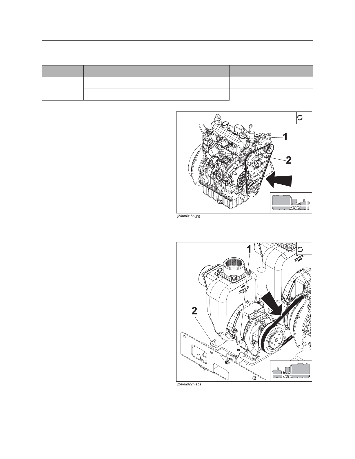
Replace Fan Belt
Replace fan belt (shown) every 500 hours.
To replace
1. Loosen bolts (1, 2) and remove belt.
2. Install new belt and adjust properly. See
page 56.
Replace Pump Drive Belt
Replace pump drive belt (shown) every 500 hours.
To replace
1. Loosen three bolts (1, 2; third bolt is on other
side of pump mount plate) and remove belt.
2. Install new belt and adjust properly. See
page 56.
CMW
FM25 Operator’s Manual Service - 55
2000 Hour
2000 Hour
Change Engine Coolant
Drain cooling system at drain (2). Add approved
coolant at fill (1) every two years or 2000 hours.
NOTICE:
• The use of non-approved coolant may lead
to engine damage or premature engine
failure and will void engine warranty.
• See “Approved Coolant” on page 48. for list
of approved coolants.
CMW

Service - 56 FM25 Operator’s Manual
As Needed
As Needed
Location Task Notes
Adjust fan belt
Adjust pump drive belt
Adjust Fan Belt
Adjust fan belt as needed.
1. Turn off engine and remove key.
2. Apply moderate thumb pressure to belt
between pulleys where shown.
Belt is properly tensioned when deflection is
about 1/4-3/8” (7-9 mm).
3. If needed, loosen alternator bolts (shown) and
pull alternator out until correct tension is
reached.
Adjust Pump Drive Belt
Adjust pump drive belt as needed.
1. Loosen two bolts (1, other bolt is on other side
of pump mount plate) until pump slides freely.
2. Adjust bolt (2) to increase or decrease tension.
When washer is aligned with cutout and
dimension A (shown) is 3/4” (19 mm), tension
is correct.
3. Once tension is set, tighten bolts.
CMW
FM25 Operator’s Manual Specifications - 57
Specifications
Component weights U.S. Metric
Pumping/power unit 1150 lb 520 kg
Mixing hopper (each) 100 lb 50 kg
500-gal (1892-L) tank and hoses (each) 500 lb 230 kg
500-gal (1892-L) tank and hoses (w/500 gal/1892 L water) 4650 lb 2100 kg
1000-gal (3785-L) tank and hoses (each) 1050 lb 480 kg
1000-gal (3785-L) tank and hoses (w/990 gal/3748 L water) 9250 lb 4200 kg
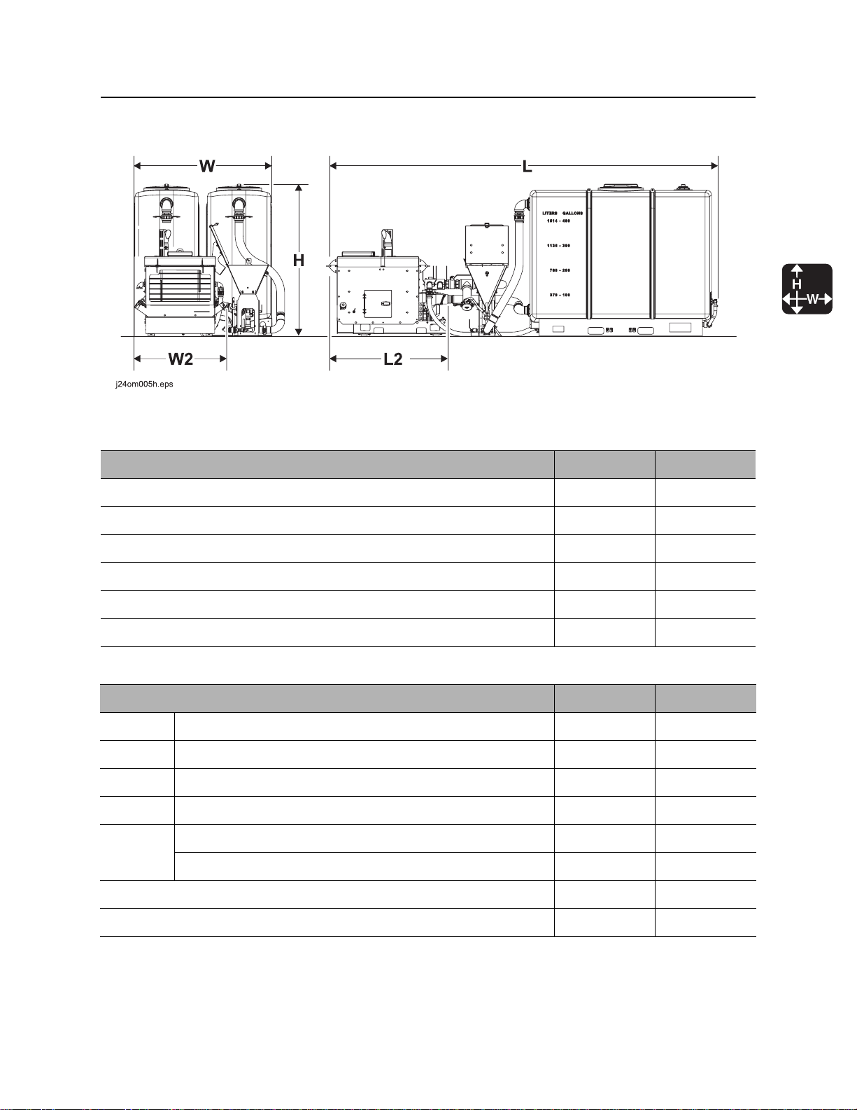
Dimensions with two 1000-gal (3785-L) tanks U.S. Metric
L Length 205 in 5.21 m
L2 Length, power unit
W Width 96 in 2.44 m
W2 Width, power unit
H Height, without fill pipe 72 in 1.83 m
Height, with fill pipe 80 in 2.03 m
Weight, dry 3450 lb 1570 kg
System weight, with fluid (990 gal/3748 L per tank) 19,850 lb 9000 kg
CMW

Specifications - 58 FM25 Operator’s Manual
Dimensions with two 500-gal (1892-L) tanks (not shown) U.S. Metric
L Length, overall 175 in 4.45 m
W Width, overall 92 in 2.34 m
H Height, without fill pipe 68 in 1.73 m
Height, with fill pipe 75 in 1.91 m
Weight, dry 2350 lb 1070 kg
System weight, with fluid (500 gal/1892 L per tank) 10, 650 lb 4830 kg
Performance U.S. Metric
Centrifugal pump suction port diameter 3 in 76 mm
Centrifugal pump discharge port diameter 3 in 76 mm
Maximum fluid pressure 50 psi 3.4 bar
Maximum pump discharge rate (each pump) 300 gpm 1135 L/min
Flow rate to drilling unit (42 viscosity fluid @ 30 psi/2.1 bar) 10-200 gpm 38-750 L/min
Drilling fluid tank capacity (nominal, each tank) 500/1000 gal 1892/3785 L
Solids addition rate with metering plate 30 lb/min 14 kg/min
Solids addition rate without metering plate 75 lb/min 34 kg/min
Dry mixing hopper capacity
1 ft
3
28 L
Typical tank mixing time 7-10 min
CMW

FM25 Operator’s Manual Specifications - 59
Engine U.S. Metric
Kubota D1105, diesel
Cooling medium water
Injection indirect
Aspiration natural
Number of cylinders 3
Displacement
68.5 in
3
1.12 L
Bore 3.07 in 78.0 mm
Stroke 3.09 in 78.4 mm
Manufacturer’s gross power (per SAE J1995) 2 4.8 hp 18.5 kW
Estimated net power rating (per SAE J1349) 21.6 hp 16.1 kW
Rated speed 3000 rpm 3000 rpm
* Exceeding these operating angles will cause engine damage. This DOES NOT IMPLY machine is stable to maximum angle of
safe engine operation.
CMW

Specifications - 60 FM25 Operator’s Manual
Fluid Capacities U.S. Metric
Fuel tank 9.2 gal 35 L
Engine oil, including filter 4.2 qt 4 L
Noise levels
Operator 88 dBA sound pressure per ISO 6394.
Exterior 101 dBA sound power per ISO 6393.
Specifications are called out according to SAE recommended practices. Specifications are general and
subject to change without notice. If exact measurements are required, equipment should be weighed and
measured. Due to selected options, delivered equipment may not match that shown.
CMW

FM25 Operator’s Manual Support - 61
Procedure
Support
Procedure
Notify your dealer immediately of any malfunction or failure of Ditch Witch equipment.
Always give model, serial number, and approximate date of your equipment purchase. This information
should be recorded and placed on file by the owner at the time of purchase.
Return damaged parts to dealer for inspection and warranty consideration if in warranty time frame.
Order genuine Ditch Witch replacement or repair parts from your authorized Ditch Witch dealer. Use of
another manufacturer's parts may void warranty consideration.
Resources
Publications
Contact your Ditch Witch dealer for publications and videos covering safety, operation, service, and repair
of your equipment.
Ditch Witch Training
For information about on-site, individualized training, contact your Ditch Witch dealer.
CMW

Warranty - 62 FM25 Operator’s Manual
Warranty
Ditch Witch Equipment and Replacement Parts
Limited Warranty Policy
Subject to the limitation and exclusions herein, free replacement parts will be provided at any authorized Ditch Witch dealership for
any Ditch Witch equipment or parts manufactured by The Charles Machine Works, Inc. (CMW) that fail due to a defect in material or
workmanship within one (1) year of first commercial use (Exception: 2 years for all SK attachments). Free labor will be provided at
any authorized Ditch Witch dealership for installation of parts under this warranty during the first year following “initial commercial”
use of the serial-numbered Ditch Witch equipment on which it is installed. The customer is responsible for transporting their
equipment to an authorized Ditch Witch dealership for all warranty work.
Exclusions from Product Warranty
• All incidental or consequential damages.
• All defects, damages, or injuries caused by misuse, abuse, improper installation, alteration, neglect, or uses other than those for
which products were intended.
• All defects, damages, or injuries caused by improper training, operation, or servicing of products in a manner inconsistent with
manufacturer’s recommendations.
• All engines and engine accessories (these are covered by original manufacturer’s warranty).
• Tires, belts, and other parts which may be subject to another manufacturer’s warranty (such warranty will be available to
purchaser).
• ALL IMPLIED WARRANTIES NOT EXPRESSLY STATED HEREIN, INCLUDING ANY WARRANTY OF FITNESS FOR A
PARTICULAR PURPOSE AND MERCHANTABILITY.
IF THE PRODUCTS ARE PURCHASED FOR COMMERCIAL PURPOSES, AS DEFINED BY THE UNIFORM COMMERCIAL
CODE, THEN THERE ARE NO WARRANTIES WHICH EXTEND BEYOND THE FACE HEREOF AND THERE ARE NO IMPLIED
WARRANTIES OF ANY KIND WHICH EXTEND TO A COMMERCIAL BUYER. ALL OTHER PROVISIONS OF THIS LIMITED
WARRANTY APPLY INCLUDING THE DUTIES IMPOSED.
Ditch Witch products have been tested to deliver acceptable performance in most conditions. This does not imply they will deliver
acceptable performance in all conditions. Therefore, to assure suitability, products should be operated under anticipated working
conditions prior to purchase.
Defects will be determined by an inspection within thirty (30) days of the date of failure of the product or part by CMW or its authorized
dealer. CMW will provide the location of its inspection facilities or its nearest authorized dealer upon inquiry. CMW reserves the right
to supply remanufactured replacements parts under this warranty as it deems appropriate.
Extended warranties are available upon request from your local Ditch Witch dealer or CMW.
Some states do not allow exclusion or limitation of incidental or consequential damages, so above limitation of exclusion may not
apply. Further, so me states do not allow exclusion of or limitation of how long an implied warranty lasts, so the above limitation may
not apply. This limited warranty gives product owner specific legal rights and the product owner may also have other rights which vary
from state to state.
For information regarding this limited warranty, contact CMW’s Product Support department, P.O. Box 66, Perry, OK 73077-0066, or
contact your local Ditch Witch dealer.
First version: 1/91; Latest version: 7/05
CMW

FM25 Operator’s Manual Service Record - 65
Service Record
Service Performed Date Hours
CMW

Service Record - 66 FM25 Operator’s Manual
Service Performed Date Hours
CMW
 Loading...