

FM13V - SERVICE 1
SERIAL NUMBER
SERVICE
SERIAL NUMBER
Record the serial numbers and date of purchase of your
equipment in the spaces below.
Date of manufacture:
Date of purchase:
Fluid mixing unit serial
number:

2 FM13V - SERVICE
SUPPORT PROCEDURE
SUPPORT PROCEDURE
Notify your dealer immediately of any malfunction or failure of
Ditch Witch equipment.
Always give model, serial number, and approximate date of your
uipment purchase. This information should be recorded and
eq
placed on file by the owner at the time of purchase.
Return damaged parts to dealer for inspection and Warranty
eration if in warranty time frame.
consid
Order genuine Ditch Witch replacement or repair parts from your
thorized Ditch Witch dealer. Use of another manufacturer's
au
parts may void warranty consideration.
RESOURCES
Publications
Contact your Ditch Witch dealer for publications and videos
covering safety, operation, service, and repair of your equipment.
Ditch Witch Training Center
For information about on-site, individualized training, contact your
Ditch Witch dealer.

FM13V - FOREWORD 3
RESOURCES
FOREWORD
This manual is an important part of your equipment. It provides
safety information and operation instructions to help you use and
maintain your Ditch Witch equipment.
Read this manual before using your equipment. Keep it with the
uipment at all times for future reference. If you sell your
eq
equipment, be sure to give this manual to the new owner.
If you need a replacement copy, conta
ct your Ditch Witch dealer.
If you need assistance in locating a dealer, visit our website at
www.ditchwitch.com or write to the following address:
The Charles Machine W
orks, Inc.
Attn: Marketing Department
PO Box 66
Perry, OK 73077-0066
USA
The descriptions and specifications in this manual are subject to
ge. The Charles Machine Works, Inc. reserves the right to
chan
improve equipment. Some product improvements may have
taken place after this manual was published. For the latest
information on Ditch Witch equipment, see your Ditch Witch
dealer.
Thank you for buying and using
Ditch Witch equipment.

4 FM13V - FOREWORD
RESOURCES
Operator's Manual
13V
FM
Issue No. 1.0/OP-1/07
t Number 053-1125
Par
Copyright 2007
by The
Charles Machine Works, Inc.,
Perry, Oklahoma
, Ditch Witch, CMW, AutoCrowd,
Modularmatic, Jet Trac, Roto Witch, Subsite, Fluid Miser, PermaSoil, Power Pipe, Super Witch, Super Witch II, Pierce Airrow, The
Underground, and The Underground Authority Worldwide are
registered trademarks of The Charles Machine Works, Inc.

FM13V - CONTENTS 5
RESOURCES
CONTENTS
SERVICE . . . . . . . . . . . . . . . . . . . . . . . . . . . . . . . . . . . . . . . 1
Serial Number . . . . . . . . . . . . . . . . . . . . . . . . . . . . . . . 1
Support Procedure . . . . . . . . . . . . . . . . . . . . . . . . . . . . 2
Resources . . . . . . . . . . . . . . . . . . . . . . . . . . . . . . . . . . 2
FOREWORD . . . . . . . . . . . . . . . . . . . . . . . . . . . . . . . . . . . . 3
OVERVIEW . . . . . . . . . . . . . . . . . . . . . . . . . . . . . . . . . . . . . 7
CONTROLS . . . . . . . . . . . . . . . . . . . . . . . . . . . . . . . . . . . . . 9
Overview . . . . . . . . . . . . . . . . . . . . . . . . . . . . . . . . . . . . 9
Descriptions. . . . . . . . . . . . . . . . . . . . . . . . . . . . . . . . . 10
SAFETY . . . . . . . . . . . . . . . . . . . . . . . . . . . . . . . . . . . . . . . 17
Accessories . . . . . . . . . . . . . . . . . . . . . . . . . . . . . . . . 18
Safety Alert Classifications . . . . . . . . . . . . . . . . . . . . . 19
Safety Alerts . . . . . . . . . . . . . . . . . . . . . . . . . . . . . . . . 20
LIFT . . . . . . . . . . . . . . . . . . . . . . . . . . . . . . . . . . . . . . . . . . 23
PREPARATION . . . . . . . . . . . . . . . . . . . . . . . . . . . . . . . . . 25
Check Equipment . . . . . . . . . . . . . . . . . . . . . . . . . . . . 26
Select Drilling Fluid . . . . . . . . . . . . . . . . . . . . . . . . . . . 26

6 FM13V - CONTENTS
RESOURCES
OPERATION . . . . . . . . . . . . . . . . . . . . . . . . . . . . . . . . . . . 29
Mix Drilling Fluid. . . . . . . . . . . . . . . . . . . . . . . . . . . . . 30
Pump Fluid to Drilling Unit . . . . . . . . . . . . . . . . . . . . . 33
LUBRICATION AND MAINTENANCE . . . . . . . . . . . . . . . 37
Overview . . . . . . . . . . . . . . . . . . . . . . . . . . . . . . . . . . 38
Engine Oil. . . . . . . . . . . . . . . . . . . . . . . . . . . . . . . . . . 39
Air Filter . . . . . . . . . . . . . . . . . . . . . . . . . . . . . . . . . . . 40
Pump . . . . . . . . . . . . . . . . . . . . . . . . . . . . . . . . . . . . . 40
TROUBLESHOOTING . . . . . . . . . . . . . . . . . . . . . . . . . . . 41
SPECIFICATIONS . . . . . . . . . . . . . . . . . . . . . . . . . . . . . . 43
FM13V . . . . . . . . . . . . . . . . . . . . . . . . . . . . . . . . . . . . 43
Drilling Fluid Tanks. . . . . . . . . . . . . . . . . . . . . . . . . . . 45
FM13V - OVERVIEW 7
RESOURCES
OVERVIEW
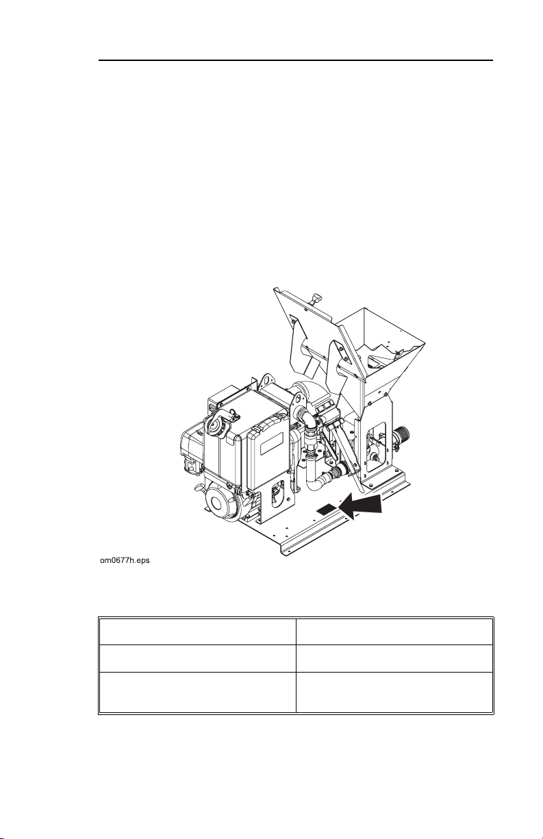
The FM13V is a platform mounted venturi mixing system which
mixes drilling fluid quickly and efficiently. It transfers drilling fluid
for use with directional drilling systems. The FM13V has two
available drilling fluid mixing tank sizes: 500 gal (1892 L) and
1000 gal (3785 L).
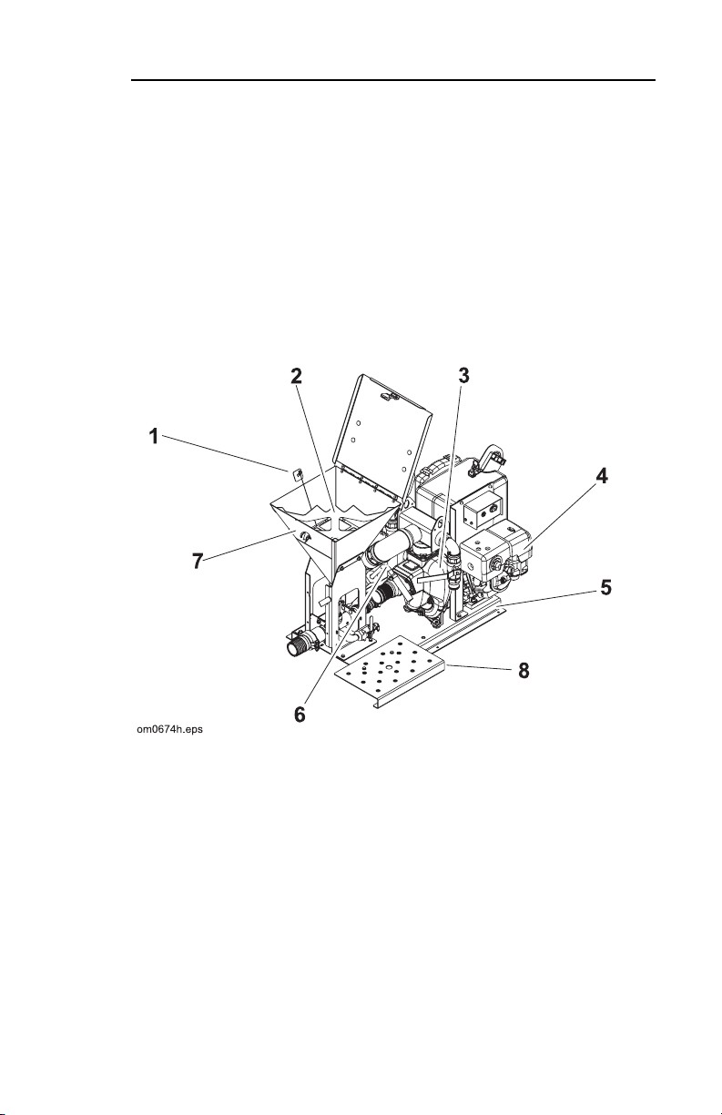
1. metering plate 5. base
2. bag ripper 6. suction wand
3. pump 7. dry chemical hopper
4. engine 8. platform

8 FM13V - OVERVIEW
RESOURCES

FM13V - CONTROLS 9
OVERVIEW
CONTROLS
OVERVIEW
Switches and Gauges
1. ignition switch 6. choke
2. auxiliary outlet (12VDC) 7. manual fuel shut-off valve
3. hourmeter 8. engine stop switch
4. throttle 9. battery disconnect
5. rope start
10 FM13V - CONTROLS
OVERVIEW
DESCRIPTIONS
Ignition Switch
This switch has three positions.
• Insert key and turn clockwise to the “ON” position.
• Turn switch all the way clockwise to the “Start” position.
• Release when engine starts. K
ey will return to on position.
• Turn counterclockwise to STOP to stop engine.
IMPORTANT Turn ignition s
witch to the STOP position any time
the engine stops running.
Auxiliary Outlet
This outlet provides auxiliary power
to electrical accessories. To
operate work lights or other 12V devices, plug into outlet.
Notice En
gine alternator is capable of delivering 3 Amps at 3600
RPM. Running engine at part throttle while using electrical
accessories, or using accessories that use more than 3 amps for
an extended time may discharge battery.
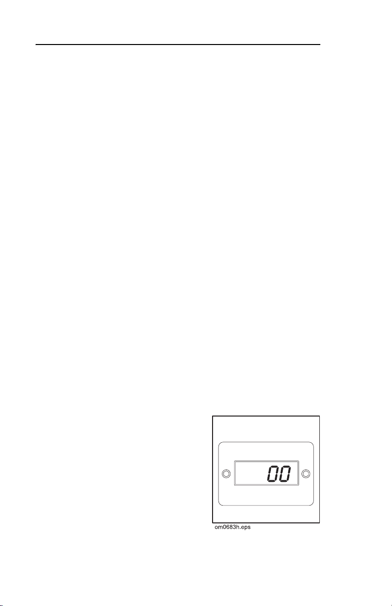
Tachometer/Hourmeter
This gauge records engine
operating time. Use these times
to schedule lubrication and
maintenance.
When engine is operating,
gine rpm is displayed.
en
When engine is not operating,
gine operating time is
en

FM13V - CONTROLS 11
OVERVIEW
displayed.
Throttle
This lever adjusts engine speed during mixing process.
• Move lever to the right to increase engine speed.
• Move lever to the left to decrease engine speed.
Rope Start
This rope is used as a backup method to start engine if electric
st
art fails. Pull rope to start engine.
Choke
This valve regulates air/fuel mixture. To help start cold engine,
close valve.

12 FM13V - CONTROLS
OVERVIEW
Manual Fuel Shut-off Valve
This valve stops the flow of fuel fro
m the fuel tank to the engine
when unit is transported or stored.
• To open valve, turn lever
to the right.
• To close valve, turn lever to the left.
Engine Stop Switch
This switch controls power to the ignition system.
• To turn power on, turn clockwise.
• To turn power off, turn counterclockwise.
Note The ig
nition switch is the preferred method of stopping
engine. For normal operation, leave this switch on all the time
and use ignition switch to stop and start unit. Turn key to the off
position when engine is not running.
Battery Disconnect
This switch connects/disconnects
power from battery during
service and long-term storage.
• To connect, move switch so that
indicator points left.
• To disconnect, move switch so that indicator point
s right.
FM13V - CONTROLS 13
DESCRIPTIONS
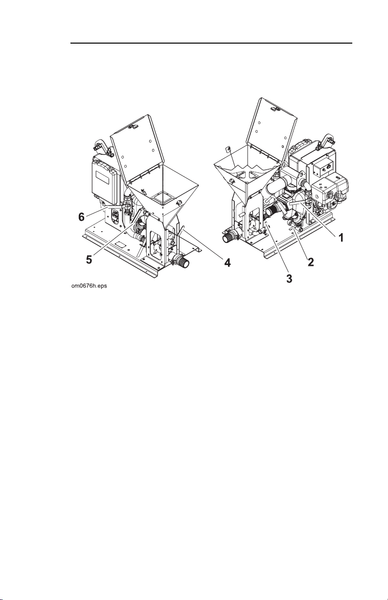
Valves
1. mixing jet valve 4. dry chemical hopper valve
2. pump drain valve 5. discharge valve
3. liquid chemical valve 6. mixing venturi valve
DESCRIPTIONS
Mixing Jet Valve
This valve controls the flow of fluid fr
tank.
• Turn valve handle counterclockwise 1/4 turn to open valve.
• Turn valve handle clockwise 1/4 turn to close valve.
om pump to the mixing jets in

14 FM13V - CONTROLS
DESCRIPTIONS
Pump Drain Valve
This valve drains fluid from pump and some fluid lines.
• Turn handle counterclockwise 1/4 turn to open.
• Turn clockwise 1/4 turn to close.
Liquid Chemical Hopper Valve
This valve controls the flow of poly
mers or wetting agents to the
mixing system.
• Turn handle counterclockwise 1/4 turn to open valve.
• Turn handle clockwise 1/4 turn to close valve.
Dry Chemical Hopper Valve
This valve controls flow of dry chem
icals into mixing venturi.
• Turn handle to left (counterclockwise) to open valve.
• Move handle to right (clockwise) to close valve.
IMPORTANT Do
not open valve unless pump is running and
mixing venturi valve is open. Fluid could flow back into hopper.
Discharge Valve
This valve controls the flow of drilling fluid from
mixing tank to
drilling unit.
• Turn handle counterclockwise 1/4 turn to open valve.
• Turn handle clockwise 1/4 turn to close valve.

FM13V - CONTROLS 15
DESCRIPTIONS
Mixing Venturi Valve
This valve controls flow of flu
id though mixing venturi at the
bottom of the dry hopper.
• Turn handle counterclockwise 1/4 turn to open.
• Turn handle clockwise 1/4 turn to close.

16 FM13V - CONTROLS
DESCRIPTIONS

FM13V - SAFETY 17
SAFETY
Follow these guidelines before operating any jobsite equipment:
• Complete proper training and read operator’s manual before
sing equipment.
u
• Contact One-Call (888-258-0808) and any utility
which do not subscribe to One-Call. Have all underground
pipes and cables located and marked before operating
equipment. If you damage a utility, contact utility company.
• Classify jobsite based on its hazards and use correct tools
d machinery, safety equipment, and work methods for
an
jobsite.
• Mark jobsite clearly and keep
• Wear personal protective equipment.
• Review jobsite hazards, safety and emergency procedures,
and indiv
begins. Safety videos are available from your Ditch Witch
dealer.
• Replace missing or damaged safety shields and safety signs.
• Use equipment carefully. Stop operation and investigate
an
• Do not operate unit where flammable gas is present.
• Contact your Ditch Witch dealer
about operation, maintenance, or equipment use.
idual responsibilities with all personnel before work
ything that does not look or feel right.
spectators away.
if you have any question
companies

18 FM13V - SAFETY
ACCESSORIES
ACCESSORIES
Fire Extinguisher
If required, a fire extinguisher should be mounted near the power
unit but away from possible points of ignition. The fire
extinguisher should always be classified for both oil and electric
fires. It should meet legal and regulatory requirements.

FM13V - SAFETY 19
SAFETY ALERT CLASSIFICATIONS
SAFETY ALERT CLASSIFICATIONS
These classifications and the icons defined on the following
pages work together to alert you to situations which could be
harmful to you, jobsite bystanders or your equipment. When you
see these words and icons in the book or on the machine,
carefully read and follow all instructions. YOUR SAFETY IS AT
STAKE.
Watch for the three safe
ty alert levels: DANGER, WARNING and
CAUTION. Learn what each level means.
indicates an imminently hazardous situation
which, if not avoided, will result in death or s
erious injury.
indicates a potentially hazardous situation which,
if not avoided, could result in death or serious injury.
indicates a potentially hazardous situation which,
if not avoided, may result in minor or moderate injury.
Watch for two other words: NOTIC
NOTICE
can keep you from doing something that might damage
E and IMPORTANT.
the machine or someone's property. It can also alert you against
unsafe practices.
IMPORTANT
can help you do a better job or make your job
easier in some way.

20 FM13V - SAFETY
SAFETY ALERTS
SAFETY ALERTS
Electric shock. Contacting electric
lines will cause death or serious injury. Know
location
presence of gas will cause sickness or death.
Pro
of lines and stay away.
Deadly gases. Lack of oxygen or
vide ventilation.
could cause death or serious injury.
correct equipment and work
Use
methods. Use and maintain proper
safety equipment.
Jobsite hazards
Crushing weight
could cause death or serious
ry. Use proper procedures and
inju
equipment or stay away.

FM13V - SAFETY 21
SAFETY ALERTS
Incorrect procedures could result
in death, injury, or property damage. Learn to use
uipment correctly.
eq
Fire or explosion possible. Fumes
could ignite and cause burn
s. No smoking, no
flame, no spark.
Moving traffic - hazardous
situation. Death or serious injury could result.
oid moving vehicles, wear high visibility clothing,
Av
post appropriate warning signs.
Improper control function could
cause death or serious injury. If control does not
as described in instructions, stop machine
work
and have it serviced.
Hot parts may cause burns. Do not
touch until cool.

22 FM13V - SAFETY
SAFETY ALERTS
Exposure to high noise levels may
cause hearing loss. Wear hearing protection.
Fall possible. Slips or trips may
result in injury. Keep area clean.
Improper handling or use of
chemicals may result in illness, injury, or
uipment damage. Follow instructions on labels
eq
and in material safety data sheets (MSDS).

FM13V - LIFT 23
LIFT
LIFT
Crushing weight. If load falls or
moves it could kill or crush you. Use proper
ocedures and equipment or stay away.
pr
LIFT
Points
Lifting points are identified by lifting
decals. Lifting at other points is
unsafe and can damage machinery.
Mixing Unit
Lift mixing unit by attaching
chains to lift points on top of
pump.
Bolt base to truck or trailer bed
sing provided holes.
u
If mounting without a base,
ure pump coupler is covered.
ens

24 FM13V - LIFT
LIFT
Tank
Lift fluid tank by attaching sling to
lift points located on side of tank.
IMPORTANT: Em
lifting.
pty tank before

FM13V - PREPARATION 25
CHECK EQUIPMENT
PREPARATION
CHECK EQUIPMENT
Check the following before starting each day’s work. Refer to
LUBRICATION AND MAINTENANCE for additional information
and locations.
• General appearance of equipment
• Safety sign location and readability
• All guard and shield locations. Replace if missing or worn.
• Condition of all wear items such as
and clamps
• Drilling fluid hoses, and electric c
wear, or other damage.
• Engine crankcase oil level. Keep
dipstick. Do not overfill.
• Fuel level. Fuel tank should be filled
reduce condensation.
• All nuts and bolts. Tighten if necessary.
strainers, filters, hoses,
ables for signs of leakage,
oil level at the highest line on
at the end of the day to

26 FM13V - PREPARATION
SELECT DRILLING FLUID
SELECT DRILLING FLUID
For productive drilling and equipment protections, use these
®
recommended Baroid
Dealer.
• Quik-Gel™ dry powder bentonite (p/n 259-804)
• E-Z Mud™ liquid polymer (p/n 259-805)
• Liqui-Trol™ liquid polymer suspension (p/n 259-808)
• Quik-Trol™ dry powder polymer (p/n 259-809)
• Bore-Gel™ drilling fluid (p/n 259-807)
• Con-Det™ water-soluble cleaning solution (p/n 259-810)
Guidelines
Match drilling fluid to soil type. Although specific conditions at
each jobsite vary, use the following guidelines when selecting a
drilling fluid.
products, available from your Ditch Witch
If soil is... use...
Smooth, flowing sand Bentonite + medium chain
po
lymer
Coarse sand or light soil Bentonite
Heavy clay Long chain polymer
Swelling clay Long chain polymer
Rock Bore-Gel
For recommended mixture to reach desired
drilling fluid viscosity
or thickness, contact your Ditch Witch dealer.

FM13V - PREPARATION 27
SELECT DRILLING FLUID
Bentonite
Bentonite is a dry powder. When properly mixed with water, it
cakes on bore walls, lubricating the bore, keeping it open, and
holding fluid in the bore.
Some things to remember when mixing bentonite:
• Use clean water free of salt, calcium, or excessive chlorine.
• Use water with pH level between 7.5 and 10.
• Do not use bentonite containing sand.
• Mix bentonite thoroughly or
it will settle in tank.
• Do not mix bentonite to a funnel viscosity of over 50.
For information on measuring funnel viscosity, read “Measuring
Funnel Viscosity
” in OPERATION.
Polymer
This drilling fluid additive provides excellent lubrication and
increases viscosity in average soils and heavy clay. In swelling
clay, polymer can reduce swelling that traps pipe in the bore.
There are two types of polymer:
• Long chain such as Baroid EZ-Mud
• Medium chain such as Baroid
Quik-Trol
Mixtures
Bentonite does not mix well in water containing polymer. To use
both, mix bentonite first, then add polymer.
Bore-Gel
Use 15 lb/100 gal (6.8 kg/378.5 L) in normal drilling conditions, up
to 45 lb/100 gal (20.4/378.5 L) in sand or gravel and up to 50 lb/
100 gal (22.6/378.5 L) in rock.
contains premixed bentonite, polymer, and soda ash.

28 FM13V - PREPARATION
SELECT DRILLING FLUID
Planning Drilling Fluid Requirements
1. Determine drilling conditions and choose appropriate drilling fluid mix.
2. Estimate amount of supplies
needed and check availability.
• Drilling fluid
• Water supply. If more water than can be carried with the
unit will be needed, arrange to trans
port additional water.
• Bentonite and/or polymer
3. Check water quality.
• Visually perform pH test on water. If pH is below 5.0, add
.25 L) soda ash per tank. Test and repeat until pH
1 cup (
is between 7.5 and 10.

FM13V - OPERATION 29
SELECT DRILLING FLUID
OPERATION
This section covers basic operation. For questions about specific
situations, contact your Ditch Witch dealer.
Jobsite hazards
could cause death or serious injury.
Use cor
methods. Use and maintain proper
safety equipment.
NOTICES:
• Wear personal protective equipment including hard hat,
safety e
ye wear, and hearing protection.
• Do not wear jewelry or loose clothing.
rect equipment and work

30 FM13V - OPERATION
Mix Drilling Fluid
Mix Drilling Fluid
1. Ensure valve in suction line and at least one valve on the pressure side of the pump is open.
2. If necessary, choke cold engine.
3. Move throttle to half open.
4. Turn ignition switch to start position and release when engine
st
arts.
IMPORTANT If battery
is dead, turn key to ON and pull start
rope.

FM13V - OPERATION 31
Mix Drilling Fluid
5. Open choke after engine is warm.
EMERGENCY SHUTDOWN Turn ignition sw
itch to STOP.
NOTICES:
• If chemicals are added in the wrong order, they w
ill not mix
properly and will form clumps. See “Mixtures” in Preparation.
• If tank contains bentonite/polyme
r mix and more drilling fluid
is needed, completely empty tank and start with fresh water
before mixing another batch.
6. Open tank jet valve (3) and mixing venturi valve (6).
7. Start engine on mixing pump.
8. Partially open dry chemical hopper valve (4). Listen for a
n
oticeable “suction” sound.
IMPORTANT Ad
d polymers at a very slow rate.
9. For dry chemicals, open sack using bag ripper located inside
y chemical hopper and pour chemicals into hopper.
dr
NOTICE
Metering plate can be seated in bottom of dry chemical
hopper to allow dry chemicals to be added at a slower rate.
• Approximate feed rate with meter
ing plate, 50 lb : 1.5 minutes.
• Approximate feed rate without metering plate, 50 lb : 0.7
min
utes.
10. Open dry chemical valve (4) slowly.
11. For liquid polymer and other liquid chemicals, pour needed
am
ount of additive into a suitable container, insert wand into
container.
12. Open liquid chemical valve (3) slowly.
13. Open fillwell on top of tank and c
heck fluid in tank to ensure
that chemicals are mixed correctly.
14. If clumps of chemical or polymer can be seen in fluid tank,
re
duce the rate at which materials are added.

32 FM13V - OPERATION
Mix Drilling Fluid
Measuring Funnel Viscosity
Viscosity is the measure of internal resistance of a fluid to flow;
the greater the resistance, the higher the viscosity. Viscosity of
drilling fluids must be controlled.
To determine viscosity, you
will need a Marsh funnel and a
measuring cup, available from your Ditch Witch Dealer.
1. Take a fresh sample from the
drilling fluid tank. The sample
st be more than 1 qt
mu
(.95 L).
2. Hold funnel over 1 qt (.95 L) measuring cup and place a finger over outlet.
3. Pour test sample into top of
el through screen to
funn
ensure no large particles
enter the funnel that might
alter the measurement. Fill to screen.
4. Remove finger and time flow. Co
unt the number of seconds
necessary for 1 qt (.95 L) of fluid to pass through funnel. The
number of seconds is the viscosity.
5. Thoroughly rinse measuring cup and Marsh funnel with water.

FM13V - OPERATION 33
PUMP FLUID TO DRILLING UNIT
PUMP FLUID TO DRILLING UNIT
Electric shock. Contacting electric
lines will cause death or serious injury. Know
location
of lines and stay away.
NOTICE: If ele
ctrical strike occurs while fluid hose
is connected to drilling unit, fluid system will also
become electrified.
1. Connect mixing pump hose to drilling unit.
NOTICE To prevent damage
to the drilling fluid pump, make sure
y-strainer is used in-line between mixing unit and drilling unit.
2. Open discharge valve of mixing pump, adjust engine throttle
to purge all air from the line when starting drilling fluid
to full
pump on drilling unit. After flow is stable, adjust throttle to
give desired flow rate to drilling unit (approximately half
throttle).
IMPORTANT:
• To reduce agitation in tank when us
ing polymer-based drilling
fluids, partially close the tank jet valve.
• Overmixing of polymer-based
drilling fluids can reduce fluid
viscosity.
• Close venturi valve when dry chemical hopper is not in use.

34 FM13V - OPERATION
DRAIN SYSTEM
DRAIN SYSTEM
Drain system under the following circumstances:
• Temperature is expected to be 32°F (0°C) or below.
• System is not going to be used for several days.
• System is going to be used on a different job requiring
ent chemicals.
differ
1. Pump as much fluid as possible out of tanks.
2. Shut off pumps and open all valves (sho
wn). Disconnect tank
jet hose.
3. Lower suction wand to allow fluid to drain from hose and mixing venturi.
4. Allow fluid to drain into suitable containers.
5. Recycle or properly dispose of fluid.
6. If needed, drain any remaining fluid in tank by removing plug
o
n bottom of tank’s suction end.

FM13V - OPERATION 35
DRAIN SYSTEM
7. When finished, pull up the ground wire and grounding stake (if used). Store in secure place.

36 FM13V - OPERATION
DRAIN SYSTEM

FM13V - LUBRICATION AND MAINTENANCE 37
DRAIN SYSTEM
LUBRICATION AND
MAINTENANCE
Fluid under pressure can pierce
skin and cause injury or death. Stay away.
NOTICES:
• Before using system, check that a
all lines are undamaged.
• Fluid leaks can be hard to detect. Use a piece of cardboard or
wood
, rather than hands, to search for leaks.
• Wear protective clothin
• If you are injured, seek im
moves, death or serious injury can result. Use
oper procedures and equipment or stay away.
pr
NOTICE: Unless otherwis
should be performed with the engine(s) shut off.
g and eye protection.
mediate medical attention.
Crushing weight. If load falls or
e instructed, all service in this chapter
ll connections are tight and

38 FM13V - LUBRICATION AND MAINTENANCE
OVERVIEW
OVERVIEW
Interval Task Page no.
daily check engine oil 39
50 hours grease pump 40
100 hours change engine oil 39
change air filter element 40
Lubricant chart:
GEO Gasoline engine oil (see chart for
NLGI #1 Polyurea based NLGI #1
meeting API engine service classification SD
appropriate SAE viscosity rating)

FM13V - LUBRICATION AND MAINTENANCE 39
ENGINE OIL
ENGINE OIL
Check Oil
Check engine oil at dipstick before
h operation. Add GEO at fill
eac
neck as necessary to keep oil level
at highest line on dipstick.
Change
Oil
Change oil every 100 hours with
.
GEO
• Pull drain plug and drain
ase while oil is still
crankc
warm.
• Refill at fill neck with 2.3 pt
(1.1 L) of GEO.

40 FM13V - LUBRICATION AND MAINTENANCE
AIR FILTER
AIR FILTER
Change foam air filter element
every 100 hours. Do not allow dirt
to fall into carburetor.
PUMP
Lube grease fitting with
Lubra-plate -630-AA every 50
urs.
ho
Grease cavity is full when grease
es from grease cylinder
escap
relief valve.

FM13V - TROUBLESHOOTING 41
PUMP
TROUBLESHOOTING
The FM13V has a metering plate in the bottom of the dry
chemical hopper sized to match material flow to fluid volume
going through venturi. This plate helps each unit maintain the
approximate time required to feed 50 lb (22.7 kg) of material into
tank when engine is running at full speed. Changing material flow
rate by removing or resizing plate will affect mixing results.
Problem Possible solutions
Slow feed rate from
opper
h
Poor drilling fluid
m
ix characteristics
Clumps in drilling
fluid
tank
Run engine at full speed
Place control valves in recommended
mixing positions
.
Clear obstructions from metering plate
nd check that screen is in place.
a
Remove build-up from venturi chamber.
Clean plugged hoses and fittings. Repair
o
r replace damaged hoses and fittings.
See pump instructions for procedure on
chec
king flow.
Test water pH and treat if necessary (see
PREPARATION for instructions).
Check feed rate.

42 FM13V - TROUBLESHOOTING
PUMP
Problem Possible solutions
Low yield properties Check feed rate.
Make sure screen is in strainer.
Check water pH.
Try different brand of drilling fluid
a
dditive.
Add polymer to drilling fluid tank only
a
fter bentonite has been yielded out.
Hourmeter does not
work.
Replace hourmeter. Contact your local
Ditch
Witch dealership for replacement
parts.
• Mount with provided screws.
• Wrap pick-up wire around spark plug
e no more than four times. Ensure
wir
that pick-up wire does not come in
contact with spark plug and is not
near a heat source (i.e. muffler).
• Attach ground wire to an engine
lock bolt.
b
Important:
Ensure that hourmeter is
not placed too close to a sound
source other than the engine. Failure
to do so will result in inaccurate
readings.

FM13V - SPECIFICATIONS 43
FM13V
SPECIFICATIONS
FM13V
Dimensions U.S. Metric
Length 60 in 1.5 m
Height 43 in 1.1 m
Width 26 in 660 mm
Weight 450 lb 204 kg
Drilling fluid system U.S. Metric
Maximum flow rate at 26 viscosity 300 gpm 1135 L/m
Mixing hopper capacity 1.0 cu ft 28 L
Drilling fluid/mixing tank 500/1000 gal 1892/3785 L
Mixing time for 50 lb (22.7 kg) 0.7 min 0.7 min
Mixing time for 100 lb (45 kg) 1.5 min 1.5 min
Fluid capacities U.S. Metric
Fuel tank 6.0 gal 22.7 L
Engine oil 2.3 pt 1.1 L

44 FM13V - SPECIFICATIONS
FM13V
Engine U.S. Metric
Engine: Honda GX390
Fuel: gasoline
Cooling medium: air
Number of cylinders: one
Displacement 23.7 cu in 389 cu cm
Bore 3.53 in 90 mm
Stroke 2.52 in 64 mm
Gross power @ 3600 rpm 13 hp 9.7 kW
Noise Level:
Operator 92 dbA sound pressure per ISO 6394.
Exterior 105 dbA sound power per ISO 6393.

FM13V - SPECIFICATIONS 45
DRILLING FLUID TANKS
DRILLING FLUID TANKS
500 gal (1893 L) tank
Dimensions U.S. Metric
Length 93 in 2.36 m
Height (H1) 68 in 1.73 m
Height (H
) 75 in 1.91 m
2
Width 30 in 800 mm
Weight (empty) 550 lb 250 kg
Weight (full of water) 4720 lb 2141 kg

46 FM13V - SPECIFICATIONS
DRILLING FLUID TANKS
1000 gal (3786 L) tank
Dimensions U.S. Metric
Length 125 in 3.18 m
Height (H1) 72 in 1.83 m
Height (H
) 79 in 2.01 m
2
Width 42 in 1.07 m
Weight (empty) 1000 lb 454 kg
Weight (full of water) 9350 lb 4241 kg
 Loading...