


C16x/C24x/C30x
Operator’s
Manual
Issue 1.1
Original Instruction
053-2869

C16x/C24x/C30x Operator’s Manual Overview - 1
Overview
Chapter Contents
Serial Number Location . . . . . . . . . . . . . . . . . . . . . . 2
Intended Use . . . . . . . . . . . . . . . . . . . . . . . . . . . . . . . 3
Equipment Modification . . . . . . . . . . . . . . . . . . . . . . 3
Unit Components . . . . . . . . . . . . . . . . . . . . . . . . . . . 4
Operator Orientation. . . . . . . . . . . . . . . . . . . . . . . . . 5
Operating Area . . . . . . . . . . . . . . . . . . . . . . . . . . . . . 5
About This Manual . . . . . . . . . . . . . . . . . . . . . . . . . . 6
• Bulleted Lists. . . . . . . . . . . . . . . . . . . . . . . . . . . . . . . . . . . . . . . . . . . . . . .6
• Numbered Lists. . . . . . . . . . . . . . . . . . . . . . . . . . . . . . . . . . . . . . . . . . . . .6

Overview - 2 C16x/C24x/C30x Operator’s Manual
Serial Number Location
Serial Number Location
Record serial numbers and date of purchase in spaces provided. Trencher serial number is located as
shown.
Item
date of manufacture
date of purchase
trencher serial number
trailer serial number
engine serial number

C16x/C24x/C30x Operator’s Manual Overview - 3
Intended Use
Intended Use
The C16x, C24x and C30x pedestrian trenchers are designed to install buried cable and pipe. The
maximum trenching depth is 36” (915 mm) for C16x and C24x and 48” (1220 mm) for C30x. The maximum
trenching width is 6” (200 mm). These un its are inte nded for operation in ambient temperatures from 2 0° to
115°F (-7° to 46°C). Use in any other way is considered contrary to the intended use.
C16x, C24x and C30x units should be used with genuine Ditch Witch
should be operated, serviced, and repaired only by persons familiar with their particular characteristics and
acquainted with the relevant safety procedures.
®
chain, teeth, and sprockets. They
Equipment Modification
This equipment was designed and built in accordance with applicable standards and regulations.
Modification of equipment could mean that it will no longer meet regulations and may not function properly
or in accordance with the operating instructions. Modification of equipment should only be made by
competent personnel possessing knowledge of applicable standards, regulations, equipment design
functionality/requirements and any required specialized testing.

Overview - 4 C16x/C24x/C30x Operator’s Manual
Unit Components
Unit Components
1. Control console
2. Engine
3. Digging boom and chain
4. Track drive

C16x/C24x/C30x Operator’s Manual Overview - 5
Operator Orientation
Operator Orientation
1. Front of unit
2. Right side of unit
3. Rear of unit
4. Left side of unit
Operating Area
The operating area (A) is at the rear of the
machine, behind the control console.
Any other area less than 6 ft (2 m) from the
machine is a danger area (B). Stay away.
6ft/2m
you to fall. Stay away.
Moving digging teeth can kill. Trench cave-in can cause
To help avoid injury:
• Keep everyone from danger area (B) during operation.
• If someone enters danger area (B) during operation, use emergency shutdown.

Overview - 6 C16x/C24x/C30x Operator’s Manual
About This Manual
About This Manual
This manual contains information for the proper use of this machine. See the beige Operation Overview
pages for basic operating procedures. Cross references such as “See page 50” will direct you to detailed
procedures.
Bulleted Lists
Bulleted lists provide helpful or important information or contain procedures that do not have to be
performed in a specific order.
Numbered Lists
Numbered lists contain illustration callouts or list steps that must be performed in order.

C16x/C24x/C30x Operator’s Manual Foreword - 7
Foreword
This manual is an important part of your equipment. It provides safety information and operation
®
instructions to help you use and maintain your Ditch Witch
Read this manual before using your equipment. Keep it with the equipmen t at all times for future reference.
If you sell your equipment, be sure to give this manual to the new owner.
If you need a replacement copy, contact your Ditch Witch dealer. If you need assistance in locating a
dealer, visit our website at www.ditchwitch.com or write to the following address:
The Charles Machine Works, Inc.
Attn: Marketing Department
PO Box 66
Perry, OK 73077-0066
USA
The descriptions and specifications in this manual are subject to change without notice. The Charles
Machine Works, Inc. reserves the right to improve equipment. Some product improvements may have
taken place after this manual was publishe d. For the latest information on Ditch Witch equipment, see your
Ditch Witch dealer.
equipment.
Thank you for buying and using Ditch Witch equipment.

Foreword - 8 C16x/C24x/C30x Operator’s Manual
C16x/C24x/C30x
Operator’s Manual
Machine Works, Inc.
Issue number 1.1/OM-02/16
Part number 053-2869
Copyright 2016
by The Charles Machine Works, Inc.
, Ditch Witch, CMW and Roto Witch are registered trademarks of The Charles
This product and its use may be covered by one or more patents at http://patents.charlesmachine.works.

C16x/C24x/C30x Operator’s Manual Contents - 9
Content s
Overview
machine serial number, information about the type of work this machine is designed
to perform, basic machine components, and how to use this manual
Foreword
part number, revision level, and publication date of this manual, and factory contact
information
Safety
machine safety alerts and emergency procedures
Operation Overview
an overview for completing a job with this machine: planning, setting up, installing
product, and restoring the jobsite; with cross references to detailed procedures
Controls
machine controls, gauges, and indicators and how to use them
Prepare
procedures for inspecting and classifying the jobsite, planning the installation path,
and preparing the jobsite for work
Drive
procedures for startup, cold start, driving, and shutdown
1
7
11
21
23
33
39
Transport
procedures for lifting, hauling, and towing
Trench
procedures for trenching
Drill
procedures for drilling
Systems and Equipment
chain, teeth, sprockets, and optional equipment
Complete the Job
procedures for backfilling and restoring the jobsite and rinsing and storing
equipment
45
51
57
71
79

Contents - 10 C16x/C24x/C30x Operator’s Manual
Service
service intervals and instructions for this machine including lubrication, replacement
of wear items, and basic maintenance
Specifications
machine specifications including weights, measurements, power ratings, and fluid
capacities
Support
the warranty policy for this machine, and procedures for obtaining warranty
consideration and training
Service Record
a record of major service performed on the machine
81
105
115
119

C16x/C24x/C30x Operator’s Manual Safety - 11
Safety
Chapter Contents
Guidelines . . . . . . . . . . . . . . . . . . . . . . . . . . . . . . . . 12
California Proposition 65 Warning . . . . . . . . . . . . 12
Emergency Procedures . . . . . . . . . . . . . . . . . . . . . 13
• Electric Strike Description. . . . . . . . . . . . . . . . . . . . . . . . . . . . . . . . . . . .13
• If an Electric Line is Damaged . . . . . . . . . . . . . . . . . . . . . . . . . . . . . . . .14
• If a Gas Line is Damaged . . . . . . . . . . . . . . . . . . . . . . . . . . . . . . . . . . . .15
• If a Fiber Optic Cable is Damaged . . . . . . . . . . . . . . . . . . . . . . . . . . . . .16
• If Machine Catches on Fire. . . . . . . . . . . . . . . . . . . . . . . . . . . . . . . . . . .16
Safety Alert Classifications . . . . . . . . . . . . . . . . . . 17
Machine Safety Alerts . . . . . . . . . . . . . . . . . . . . . . 18
Attachment Safety Alerts . . . . . . . . . . . . . . . . . . . 20
• Roto Witch® Drilling Attachment. . . . . . . . . . . . . . . . . . . . . . . . . . . . . . .20

Safety - 12 C16x/C24x/C30x Operator’s Manual
Guidelines
Guidelines
Follow these guidelines before operating any jobsite equipment:
• Complete proper training and read operator’s manual before using equipment.
• Contact your local One-Call (811 in USA) or the One-Call referral number (888-258-0808 in USA and
Canada) to have underground utilities located before digging. Also contact any utilities that do not
participate in the One-Call service. Mark proposed p ath with white paint prior to cont acting One- Call or
utilities.
• Classify jobsite based on its hazards and use cor rect tools and machin ery, safety equipment, and work
methods for jobsite.
• Mark jobsite clearly and keep spectators away.
• Wear personal protective equipment.
• Review jobsite hazards, safety and emergency procedures, and individual responsibilities with all
personnel before work begins. Safety videos are available from your Ditch Witch
www.ditchwitch.com/safe.
• Fully inspect equipment before operating. Repair or replace any worn or damaged parts. Replace
missing or damaged safety shields and safety signs. Contact your Ditch Witch dealer for assistance.
®
dealer or at
• Use equipment carefully. Stop operation and investigate anything that does not look or feel right.
• Do not operate unit where flammable gas may be present.
• Only operate equipment in well-ventilated areas.
• Contact your Ditch Witch dealer if you have any question about operation, ma intenance, or equipment
use.
• Complete the equipment checklist located at www.ditchwitch.com/safe.
California Proposition 65 Warning
This product may contain chemicals known to the State of California to cause cancer, birth defects, or
other reproductive harm.
• battery posts, terminals and related accessories
• engine exhaust
• ethylene glycol

C16x/C24x/C30x Operator’s Manual Safety - 13
Emergency Procedures
Emergency Procedures
Jobsite hazards could cause death or serious injury. Use
correct equipment and work methods. Use and maintain proper safety
equipment.
Before operating any equipment, review emergency proc edures and check that all safety precau tions have
been taken.
EMERGENCY SHUTDOWN: Release controls and turn ignition switch to OFF position.
Electric Strike Description
Electric shock. Contacting electric lines will cause death
or serious injury. Know location of lines and stay away.
When working near electric cables, remember the following:
• Electricity follows all paths to ground, not just path of least resistance.
• Pipes, hoses, and cables will conduct electricity back to all equipment.
• Low voltage current can injure or kill. Many work-related electrocutions result from contact with less
than 440 volts.
Most electric strikes are not noticeable, but indications of a strike include:
• power outage
•smoke
•explosion
• popping noises
• arcing electricity
If any of these occur, assume an electric strike has occurred.

Safety - 14 C16x/C24x/C30x Operator’s Manual
Emergency Procedures
If an Electric Line is Damaged
If you suspect an electric line has been damaged and you are near pedestrian unit, DO NOT MOVE and
do not touch unit. Take the following actions. The order and degree of action will depend upon the
situation.
• Warn people nearby that an electric strike has occurred. Instruct them to leave the area and contact
utility.
• Do not allow anyone into area until given permission by utility company.
• Do not allow anyone to touch equipment.

C16x/C24x/C30x Operator’s Manual Safety - 15
Emergency Procedures
If a Gas Line is Damaged
Fire or explosion possible. Fumes could ignite and cause
burns. No smoking, no flame, no spark.
Explosion possible. Serious injury or equipment damage could occur.
Follow directions carefully.
If you suspect a gas line has been damaged, take the following actions. The orders and degree of action
will depend on the situation.
• Immediately shut off engine(s), if this can be done safely and quickly.
• Remove any ignition source(s), if this can be done safely and quickly.
• Warn others that a gas line has been cut and that they should leave the area.
• Leave jobsite as quickly as possible.
• Immediately call your local emergency phone number and utility company.
• If jobsite is along street, stop traffic from driving near jobsite.
• Do not return to jobsite until given permission by emergency personnel and utility company.

Safety - 16 C16x/C24x/C30x Operator’s Manual
Emergency Procedures
If a Fiber Optic Cable is Damaged
Do not look into cut ends of fiber optic or unidentified cable. Vision damage can occur. Contact utility
company.
If Machine Catches on Fire
Perform emergency shutdown procedure and then take the following actions. The order and degree of
action will depend on the situation.
• Immediately move battery disconnect switch (if equipped and accessible) to disconnect position.
• If fire is small and fire extinguisher is available, attempt to extinguish fire.
• If fire cannot be extinguished, leave area as quickly as possible and contact emergency personnel.

C16x/C24x/C30x Operator’s Manual Safety - 17
Safety Alert Classifications
Safety Alert Classifications
These classifications and the icons defined on the following pages work together to alert you to situations
which could be harmful to you, jobsite bystanders or your equipment. When you see these words and
icons in the book or on the machine, carefully read and follow all instructions. YOUR SAFETY IS AT
STAKE.
Watch for the three safety alert levels: DANGER, WARNING and CAUTION. Learn what each level
means.
indicates a hazardous situation that, if not avoided, will result in death or serious injury.
This signal word is to be limited to the most extreme situations.
indicates a hazardous situation that, if not avoided, could result in death or serious injury.
indicates a hazardous situation that, if not avoided, could result in minor or moderate
injury.
Watch for two other words: NOTICE and IMPORTANT.
NOTICE indicates information considered important, but not hazard-related (e.g., messages relating to
property damage).
IMPORTANT can help you do a better job or make your job easier in some way.

Safety - 18 C16x/C24x/C30x Operator’s Manual
6ft/2m
Machine Safety Alerts
Machine Safety Alerts
Lift point. See Transport chapter for more information.
274-442
1
Moving digging teeth can kill. Trench cave-in can
2
cause you to fall. Stay away.
270-6900
Jobsite hazards could cause death or serious
3
injury. Use correct equipment and work methods. Use and
maintain proper safety equipment.
700-133
Read operator’s manual. Follow safety rules and
4
know how to use all controls. Your safety is at stake.
273-475

C16x/C24x/C30x Operator’s Manual Safety - 19
Machine Safety Alerts
Exposure to high noise levels may cause hearing
5
6
7A*
7B**
loss. Wear hearing protection.
Tiedown location. See Transport chapter for more information.
274-318
Fire or explosion possible. Fumes could ignite
and cause burns. No smoking, no flame, no spark.
Fire or explosion possible. Fumes could ignite
and cause burns. No smoking, no flame, no spark.
700-009 (2P)
275-419 (2P)
275-419 (2P)
8
9
* C16x
** C24x, C30x
Tip over possible. When loading/unloading run
at low idle and keep boom low.
Moving digging teeth can kill. Trench cave-in can
cause you to fall. Stay away.
270-6704

Safety - 20 C16x/C24x/C30x Operator’s Manual
Attachment Safety Alerts
Attachment Safety Alerts
Roto Witch® Drilling Attachment
197
Rotating shaft will kill or seriously injure. Stay away. 275-

C16x/C24x/C30x Operator’s Manual Operation Overview - 21
Operation Overview
Chapter Contents
Plan . . . . . . . . . . . . . . . . . . . . . . . . . . . . . . . . . . . . . 22
Trench . . . . . . . . . . . . . . . . . . . . . . . . . . . . . . . . . . . 22
Leave Jobsite . . . . . . . . . . . . . . . . . . . . . . . . . . . . . 22

Operation Overview - 22 C16x/C24x/C30x Operator’s Manual
Plan
Plan
1. Gather information about jobsite. See page 33.
2. Inspect jobsite. See page 35.
3. Classify jobsite. See page 36.
4. Select best chain type and tooth pattern for your application. See page 72.
5. Consider optional equipment, if necessary. See page 74.
6. Check supplies and prepare equipment. See page 38.
7. Load unit onto trailer. See page 47.
Trench
1. Unload unit from trailer. See page 50.
2. Leave optional backfill blade, if equipped, in stowed position with digging boom low to ground. See
page 75.
3. Start unit. See page 40.
4. Drive to starting point of trench. See page 41.
5. Dig the trench. See page 54.
6. Shut down unit. See page 43.
Leave Jobsite
1. Restore the jobsite. See page 80.
2. Rinse unit and stow tools. See page 80.
3. Load unit onto trailer. See page 47.

C16x/C24x/C30x Operator’s Manual Controls - 23
Controls
Chapter Contents
Control Console . . . . . . . . . . . . . . . . . . . . . . . . . . . 24
C16x Engine Controls. . . . . . . . . . . . . . . . . . . . . . . 27
C24x Engine Controls. . . . . . . . . . . . . . . . . . . . . . . 29
C30x Engine Controls. . . . . . . . . . . . . . . . . . . . . . . 31

Controls - 24 C16x/C24x/C30x Operator’s Manual
Control Console
Control Console
1. Boom lift control
®
2. Digging chain/Roto Witch
Item Description Notes
1. Boom lift control To lower boom, push.
control
To raise boom, pull.
3. Speed/Direction controls
4. Hourmeter/Tachometer (C16x and C30x only)

C16x/C24x/C30x Operator’s Manual Controls - 25
Control Console
Item Description Notes
2. Digging chain control To start digging chain, pull
toward operator, then push
down to dig position.
T o stop digging chain, rele ase
control.
To dislodge a rock or other
obstruction, pull up on control
to reverse chain.
IMPORTANT: This control
changes function when
equipped with optional Roto
®
Witch
In drill mode:
To drill clockwise, push down.
To stop drill rotation, release
control.
To drill counterclockwise, pull
up.
.
Trenching movement is always
backward (toward you).
NOTICE: Do not attempt to travel with
digging chain control pulled up (chain
in reverse position).
3. Speed/direction
controls
To drive straight forward,
push BOTH controls slowly
forward.
To drive straight in reverse,
pull BOTH controls slowly
rearward.
To turn left, move RIGHT
speed/direction control for
forward or reverse.
To turn right, move LEFT
speed/direction control for
forward or reverse.
To go faster in any direction,
move controls farther from
neutral position.
To stop, release controls.
Trenching movement is always
backward (toward you).

Controls - 26 C16x/C24x/C30x Operator’s Manual
Control Console
Item Description Notes
4. Hourmeter/tachometer Displays engine operating
time and engine speed.
Use engine operating times to
schedule service.

C16x/C24x/C30x Operator’s Manual Controls - 27
c00ic243h.eps
C16x Engine Controls
C16x Engine Controls
1. Throttle control
2. Choke control
Item Description Notes
1. Throttle control To increase engine speed,
pull up.
To decrease engine speed,
push down.
3. Ignition switch
4. Fuel shut-off valve

Controls - 28 C16x/C24x/C30x Operator’s Manual
C16x Engine Controls
Item Description Notes
2. Choke control To close choke valve, pull
choke control.
3. Ignition switch To start engine, turn key all
the way clockwise. Release
key as engine starts.
To stop engine, turn key
counterclockwise.
4. Fuel shut-off valve To stop fuel flow from fuel
tank to engine, turn valve
clockwise.
To allow fuel flow, turn valve
counterclockwise.
Close valve to enrich air/fuel mixture
and help start cold engine.
Open choke valve after engine runs
for a few seconds.
Close valve when transporting unit to
or from jobsite, or whenever machine
is parked.

C16x/C24x/C30x Operator’s Manual Controls - 29
C24x Engine Controls
C24x Engine Controls
1. Throttle control
2. Choke control
3. Ignition switch
Item Description Notes
1. Throttle control To increase engine speed,
pull up.
To decrease engine speed,
push down.
4. Oil pressure indicator
5. Hourmeter

Controls - 30 C16x/C24x/C30x Operator’s Manual
C24x Engine Controls
Item Description Notes
2. Choke control To close choke valve, pull
choke control.
3. Ignition switch To start engine, turn key all
the way clockwise. Release
key as engine starts.
To stop engine, turn key
counterclockwise.
4. Oil alert Indicator Lights when oil level is too
low. Engine will not start.
Close valve to enrich air/fuel mixture
and help start cold engine.
Open choke valve after engine runs
for a few seconds.
Check oil level. Add oil as needed.
5. Hourmeter Displays number of hours
engine has operated.

C16x/C24x/C30x Operator’s Manual Controls - 31
c00ic243h.eps
C30x Engine Controls
C30x Engine Controls
1. Throttle control
2. Choke control
Item Description Notes
1. Throttle control To increase engine speed,
pull up.
To decrease engine speed,
push down.
3. Ignition switch

Controls - 32 C16x/C24x/C30x Operator’s Manual
C30x Engine Controls
Item Description Notes
2. Choke control To close choke valve, pull
choke control.
3. Ignition switch To start engine, turn key all
the way clockwise. Release
key as engine starts.
To stop engine, turn key
counterclockwise.
Close valve to enrich air/fuel mixture
and help start cold engine.
Open choke valve after engine runs
for a few seconds.

C16x/C24x/C30x Operator’s Manual Prepare - 33
Prep are
Chapter Contents
Gather Information . . . . . . . . . . . . . . . . . . . . . . . . . 34
• Review Job Plan . . . . . . . . . . . . . . . . . . . . . . . . . . . . . . . . . . . . . . . . . . .34
• Notify One-Call Services. . . . . . . . . . . . . . . . . . . . . . . . . . . . . . . . . . . . .34
• Arrange for Traffic Control. . . . . . . . . . . . . . . . . . . . . . . . . . . . . . . . . . . .34
• Plan for Emergency Services . . . . . . . . . . . . . . . . . . . . . . . . . . . . . . . . .34
Inspect Site . . . . . . . . . . . . . . . . . . . . . . . . . . . . . . . 35
• Identify Hazards . . . . . . . . . . . . . . . . . . . . . . . . . . . . . . . . . . . . . . . . . . .35
Classify Jobsite. . . . . . . . . . . . . . . . . . . . . . . . . . . . 36
• Inspect Jobsite . . . . . . . . . . . . . . . . . . . . . . . . . . . . . . . . . . . . . . . . . . . .36
• Select a Classification. . . . . . . . . . . . . . . . . . . . . . . . . . . . . . . . . . . . . . .36
• Apply Precautions. . . . . . . . . . . . . . . . . . . . . . . . . . . . . . . . . . . . . . . . . .37
Check Supplies and Prepare Equipment . . . . . . . 38
• Supplies . . . . . . . . . . . . . . . . . . . . . . . . . . . . . . . . . . . . . . . . . . . . . . . . .38
• Fluid Levels. . . . . . . . . . . . . . . . . . . . . . . . . . . . . . . . . . . . . . . . . . . . . . .38
• Condition and Function. . . . . . . . . . . . . . . . . . . . . . . . . . . . . . . . . . . . . .38
• Accessories. . . . . . . . . . . . . . . . . . . . . . . . . . . . . . . . . . . . . . . . . . . . . . .38

Prepare - 34 C16x/C24x/C30x Operator’s Manual
Gather Information
Gather Information
A successful job begins before you dig. The first step in planning is revie wing information already available
about the job and jobsite.
Review Job Plan
Review blueprints or other plans. Check for information about exi sting or planned structur es, elevations, or
proposed work that may be taking place at the same time.
Notify One-Call Services
Contact your local One-Call (811 in USA) or the One-Call referral number (888-258-0808 in USA and
Canada) to have underground utilities located before digging. Also contact any utilities that do not
participate in the One-Call service.
Arrange for Traffic Control
If working near a road or other traffic area, contact local authorities about safety procedures and
regulations.
Plan for Emergency Services
Have the telephone numbers for local emergency and medical facilities on hand. Check that you will have
access to a telephone.

C16x/C24x/C30x Operator’s Manual Prepare - 35
Inspect Site
Inspect Site
Inspect jobsite before transporting equipment. Check for the following:
• changes in elevation such as hills or other open trenches
• obstacles such as buildings, railroad crossings, or streams
• signs of utilities. See “Inspect Jobsite” on page 36.
•traffic
•access
• soil type and condition
Identify Hazards
Identify safety hazards and classify jobsite. See “Classify Jobsite” on page 36.
Jobsite hazards could cause death or serious injury. Use
correct equipment and work methods. Use and maintain proper safety
equipment.
To help avoid injury:
• Wear personal protective equipment including hard hat, safety glasses and hearing protection.
• Do not wear jewelry or loose clothing.
• Notify One-Call and companies which do not subscribe to One-Call.
• Comply with all utility notification regulations before digging or drilling.
• Verify location of previously marked underground hazards.
• Mark jobsite clearly and keep spectators away.
Remember, jobsite is classified by hazards in place -- not by line being installed.

Prepare - 36 C16x/C24x/C30x Operator’s Manual
Classify Jobsite
Classify Jobsite
Inspect Jobsite
• Follow U.S. Department of Labor regulations on excavating and trenching (Part 1926, Subpar t P) and
other similar regulations.
• Contact your local One-Call (811 in USA) or the One-Call referral number (888-258-0808 in USA and
Canada) to have underground utilities located before digging. Also contact any utilities that do not
participate in the One-Call service.
• Inspect jobsite and perimeter for evidence of underground hazards, such as:
– “buried utility” notices
– utility facilities without overhead lines
– gas or water meters
– junction boxes
– drop boxes
– light poles
– manhole covers
– sunken ground
• Have an experienced locating equipment operator sweep area within 20’ (6 m) to each side of trench
path. Verify previously marked line and cable locations.
• Mark location of all buried utilities and obstructions.
• Classify jobsite.
Select a Classification
Jobsites are classified according to underground hazards present.
If working... then classify jobsite as...
within 10’ (3 m) of a buried electric line electric
within 10’ (3 m) of a natural gas line natural gas
in sand or granite which is capable of producing crystalline silica
(quartz) dust
within 10’ (3 m) of any other hazard other
IMPORTANT: If you have any doubt about jobsite classification, or if jobsite might contain unmarked
hazards, take steps outlined previously to identify hazards and classify jobs ite be fo re wor kin g.
crystalline silica (quartz) dust

C16x/C24x/C30x Operator’s Manual Prepare - 37
Classify Jobsite
Apply Precautions
Once classified, precautions appropriate for jobsite must be taken.
Electric Jobsite Precautions
Use one or both of these methods.
• Expose line by careful hand digging or soft excavation.
• Have service shut down while work is in progress. Have electric company test lines before returning
them to service.
Natural Gas Jobsite Precautions
In addition to positioning equipment upwind from gas lines, use one or both of these methods.
• Expose lines by careful hand digging or soft excavation.
• Have gas shut off while work is in progress. Have gas company test lines before returning them to
service.
Crystalline Silica (Quartz) Dust Precautions
Crystalline silica dust is a naturally occurring substance found in soil, sand, concrete, granite, and quartz.
Breathing silica dust particles while cutting, drilling, or working materials may cause lung disease or
cancer. To reduce exposure:
• Use water spray or other means to control dust.
• Refer to U.S. Department of Labor Occupational Safety and Health Administration guidelines to learn
more about appropriate breathing protection and permissible exposure limits.
Other Jobsite Precautions
You may need to use different methods to safely avoid other underground hazards. Talk with those
knowledgeable about hazards present at each site to determine which precautions should be taken or if
job should be attempted.

Prepare - 38 C16x/C24x/C30x Operator’s Manual
Check Supplies and Prepare Equipment
Check Supplies and Prepare Equipment
Supplies
•fuel
•keys
• personal protective equipment, such as hard hat and safety glasses
Fluid Levels
•fuel
• hydraulic fluid
• battery charge
• engine oil
Condition and Function
• digging chain and teeth
• filters (air, oil, hydraulic, and fuel if equipped)
• tires and tracks
• pumps and motors
• hoses and valves
• signs, guards, and shields
Accessories
Fire Extinguisher
If required, mount a fire extinguisher near the power unit but away from possible points of ignition. The fire
extinguisher should always be classified for both oil and electric fires. It should meet legal and regulatory
requirements.

C16x/C24x/C30x Operator’s Manual Drive - 39
Drive
Chapter Contents
Start . . . . . . . . . . . . . . . . . . . . . . . . . . . . . . . . . . . . . 40
Drive. . . . . . . . . . . . . . . . . . . . . . . . . . . . . . . . . . . . . 41
Drive on a Slope . . . . . . . . . . . . . . . . . . . . . . . . . . . 42
Shut Down. . . . . . . . . . . . . . . . . . . . . . . . . . . . . . . . 43

Drive - 40 C16x/C24x/C30x Operator’s Manual
Start
Start
1. Ensure all controls are in neutral.
2. If necessary, use choke control to start cold engine.
Fire or explosion possible.
To help avoid injury: Do not use starter fluid.
3. Move throttle to 1/4 open.
4. Turn ignition switch to START position to crank engine.
5. Release key when engine starts.
IMPORTANT: If engine does not start, turn ignition switch to OFF position and check for fuel
blockage or electrical system problems .
6. Run engine at half throttle or less for five minutes before operating trencher.
7. During warm-up, do a check of all controls. Ensure they operate correctly.
Incorrect control function can cause death or serious
injury.
To help avoid injury:
If controls do not operate as given in instructions:
• Shut down machine immediately.
• Have machine repaired.
EMERGENCY SHUTDOWN: Release controls and turn ignition switch to OFF position.

C16x/C24x/C30x Operator’s Manual Drive - 41
Drive
Drive
1. Remove parking pin from parking position (2)
and insert it in drive position (1).
2. Pull boom control to raise digging boom.
3. Move throttle to 3/4 open.
4. Move speed/direction control in direction of
preferred travel. Ground speed increases with
control movement.

Drive - 42 C16x/C24x/C30x Operator’s Manual
Drive on a Slope
Drive on a Slope
Machine can tip over and crush you.
To help avoid injury:
• Operate from uphill side of machine.
• Keep digging boom low.
• Drive cautiously at all times.
• Never jerk control levers. Use a steady even motion.
If the machine tips over, there is a risk of fuel leakage.
Fire or explosion can cause death or serious injuries.
To help avoid injury: If the machine tips over, turn ignition switch to OFF
position or close the fuel shutoff valve.
Driving safely on a slope depends upon many factors including:
• Distribution of machine weight (weight of machine may change due to configuration)
• Even or rough ground conditions
• Potential for ground giving way causing unplanned tilt forward, reverse or sideways
• Nearness of ditches, ruts, stumps or other obstructions and sudden changes in slope
• Speed
• Turning
• Operator skill
These varying factors make it impractical to specify a maximum safe operating angle in this manual. It is
therefore important for the operator to be awa re of these conditions and adjust operation accordingly.
Maximum engine angle and braking performance are two absolute limits which must never be exceeded.
These maximums are stated below since they are design limits. These design limits usually exceed the
operating limits and must never be used alone to establish safe operating angle for variable conditions.
Maximum engine lubrication angle – 20°
Maximum service brake retarding force – equal to traction of both tracks
Maximum secondary brake retarding force – equal to traction of one track

C16x/C24x/C30x Operator’s Manual Drive - 43
Shut Down
Shut Down
1. Release speed/direction controls.
2. Push boom control to lower digging boom, if
space allows.
3. Insert parking pin in the correct parking
hole (2).
IMPORTANT: The stopping position of
the gear (3) determines the correct
parking hole.
4. Run engine at low throttle for three minutes to
cool.
5. Turn ignition switch to OFF position.
6. If present, close fuel shut-off valve.
7. Remove key.
8. If you park machine on a slope: block tracks with wooden blocks and engage parking pin.

Drive - 44 C16x/C24x/C30x Operator’s Manual
Shut Down

C16x/C24x/C30x Operator’s Manual Transport - 45
Transport
Chapter Contents
Lift . . . . . . . . . . . . . . . . . . . . . . . . . . . . . . . . . . . . . . 46
• Lifting points . . . . . . . . . . . . . . . . . . . . . . . . . . . . . . . . . . . . . . . . . . . . . .46
• Lift . . . . . . . . . . . . . . . . . . . . . . . . . . . . . . . . . . . . . . . . . . . . . . . . . . . . .46
Haul . . . . . . . . . . . . . . . . . . . . . . . . . . . . . . . . . . . . . 47
• Load . . . . . . . . . . . . . . . . . . . . . . . . . . . . . . . . . . . . . . . . . . . . . . . . . . . .47
• Tie down . . . . . . . . . . . . . . . . . . . . . . . . . . . . . . . . . . . . . . . . . . . . . . . . .48
• Unload. . . . . . . . . . . . . . . . . . . . . . . . . . . . . . . . . . . . . . . . . . . . . . . . . . .50
Retrieve . . . . . . . . . . . . . . . . . . . . . . . . . . . . . . . . . . 50

Transport - 46 C16x/C24x/C30x Operator’s Manual
Lift
Lift
Crushing weight could cause death or serious injury. Stay
away.
To help avoid injury:
• Use applicable lifting device and lifting equipment.
• Only use approved lifting points.
• Stay away from lifted load.
Lifting points
Lifting points are identified by lifting decals.
Lift
Use a hoist and lifting accessories adapted to the size and weight of the
machine. See “S pecification s” on p age 105 or measure and weigh machine
before lifting.
1. Use approved methods to attach lifting accessories.
2. Use lifting device to carefully tension lifting slings.
3. Slowly lift machine.

C16x/C24x/C30x Operator’s Manual Transport - 47
Haul
Haul
Load
IMPORTANT: Use Ditch Witch S2B trailer for transport. If you use a different trailer, obey additional
instructions from the manufacturer. Load trencher as far to the front of the trailer as possible.
Prepare trailer
1. Attach trailer to vehicle.
2. Park vehicle with trailer on level and firm ground.
Load machine
Crushing weight could cause death or serious injury. Stay
away.
To help avoid injury:
• Keep boom as low as possible during loading procedure.
• Ensure ten to fifteen percent of total weight (machine plus trailer) is on tongue of trailer.
1. If equipped, put backfill blade in stowed position. See “Backfill Blade” on page 75.
2. Remove parking pin from parking position.
3. Start engine.
4. Pull boom control to slightly raise digging boom.
5. Move machine to rear of trailer. Have boom face ramps. Align tracks with ramps and machine with
center of trailer bed.
6. Set engine to low throttle.
7. Move speed/direction control slowly and push to appropriate speed.
8. Drive unit onto trailer, digging boom first, until tiedown position is reached.
9. If space allows, push boom control to lower digging boom onto trailer.
10. Engage parking pin in parking position and shut down unit. If present, turn fuel shut-off to off position.

Transport - 48 C16x/C24x/C30x Operator’s Manual
Haul
Tie Down
Crushing weight could cause death or serious injury. Stay
away
To help avoid injury:
• Only use approved tiedown points.
• Use applicable tiedown equipment.
Tiedown points
Tiedown points are identified by tiedown decals.
Procedure
With Tie-Down Kit on S2B Trailer
1. Use pins to secure front and rear of machine to trailer.
2. Secure rear latch in lower holes as shown in inset when latch is not in use.

C16x/C24x/C30x Operator’s Manual Transport - 49
Haul
Without Tie-Down Kit
1. Loop tiedowns around unit at tie-down points.
2. Ensure tiedowns are tight before transport.

Transport - 50 C16x/C24x/C30x Operator’s Manual
Retrieve
Unload
IMPORTANT: Use Ditch Witch S2B trailer for transport. If you use a different trailer, obey additional
instructions from the manufacturer.
Prepare trailer
1. Park vehicle with trailer on level and firm ground.
2. Ensure trailer is correctly attached to vehicle.
Unload machine
Crushing weight could cause death or serious injury. Stay
away.
To help avoid injury:
• Keep all persons away from machine and trailer.
• Keep boom as low as possible during unloading procedure.
1. Lower trailer or ramps.
2. Remove tiedowns.
3. If present, open fuel shut-off valve.
4. Start engine and set to low throttle.
5. Remove parking pin from parking position.
6. Pull boom control to raise digging boom, but keep it as low as possible.
7. Slowly back unit down trailer or ramps.
Retrieve
NOTICE: Machine is not approved for towing. Towing can damage components.
• Do not tow machine.
1. If machine becomes defective, repair on location or use lifting procedure to retrieve machine.
2. If machine cannot be repaired or lifted, contact customer support.

C16x/C24x/C30x Operator’s Manual Trench - 51
Trench
Chapter Contents
Precautions . . . . . . . . . . . . . . . . . . . . . . . . . . . . . . . 52
Set Up. . . . . . . . . . . . . . . . . . . . . . . . . . . . . . . . . . . . 53
Operate . . . . . . . . . . . . . . . . . . . . . . . . . . . . . . . . . . 54
• Dig Trench. . . . . . . . . . . . . . . . . . . . . . . . . . . . . . . . . . . . . . . . . . . . . . . .54
• Remove Objects from Digging Chain . . . . . . . . . . . . . . . . . . . . . . . . . . .55
Finish Job . . . . . . . . . . . . . . . . . . . . . . . . . . . . . . . . 55

Trench - 52 C16x/C24x/C30x Operator’s Manual
Precautions
Precautions
Electric shock will cause death or serious injury.
To help avoid injury:
• Know location of electrical lines and stay away.
• Carefully expose lines by hand before digging.
Read operator’s manual. Know how to use all controls.
Your safety is at stake.
Jobsite hazards could cause death or serious injury.
To help avoid injury:
• Comply with all utility notification regulations before digging or drilling.
• Notify companies that do not subscribe to One-Call.
• Set up warning barriers and keep people away from machine and jobsite.
Cutting, drilling, or working materials such as concrete,
sand, or rock containing quartz can result in exposure to silica dust.
Breathing silica dust can cause lung disease.
To help avoid injury:
• Use water spray or other appropriate means to control dust.
• Use appropriate breathing protection when exposed to silica dust.
Flying objects thrown by machine may strike people.
To help avoid injury: Wear hard hat and safety glasses.

C16x/C24x/C30x Operator’s Manual Trench - 53
Set Up
Set Up
1. Ensure all preparatory tasks have been
done correctly. See “Prepare” on page 33.
2. Ensure engine is shut down.
3. Ensure restraint bar is installed correctly:
• Danger word must be facing up, as
shown.
• Restraint bar must be in correct
position. See “Check Restraint Bar
Position” on page 93.
IMPORTANT: Trench cleaner shown
installed on restraint bar is optional.
4. If equipped, remove backfill blade. See
“Backfill Blade” on page 75.
5. Install correct counterweight configuration.
See “Counterweights” on page 76.

Trench - 54 C16x/C24x/C30x Operator’s Manual
Operate
Operate
Dig Trench
6ft/2m
To help avoid injury:
• Keep everyone at least 6’ (2 m) from machine, digging boom, and their range of movement.
• Allow 3’ (1 m) between end of chain and obstacle. Machine may move when chain starts to dig.
• St and b ack from co nsole an d ho ld con trols lo osel y. Digging chain on top side of boom can catch on
root or rock, forcing handlebar down suddenly.
1. Start engine. See “Start” on page 40.
2. Drive machine to starting point. Move in
line with planned trench.
3. Move throttle to half open.
4. Push boom control to lower digging boom
to just above ground.
5. Push digging chain control to dig position.
• DIGGING CHAIN WILL MOVE.
you to fall. Stay away.
Moving digging teeth can kill. Trench cave-in can cause
• Trenching movement is toward you.
EMERGENCY STOP: Release controls
and turn ignition switch to OFF position.
6. Increase engine speed to full throttle.
7. Slowly push boom control to lower digging
boom to desired trench depth.
8. Slowly move speed/direction control to
desired speed.
NOTICE: Incorrect use will damage
machine.
• Do not make sharp turns.
• Lower boom to full depth when
turning.

C16x/C24x/C30x Operator’s Manual Trench - 55
Finish Job
Remove Objects from Digging Chain
If object becomes lodged in chain:
1. Move attachment speed/direction control to neutral.
2. Slightly raise boom.
3. Reverse chain direction.
If object stays lodged in chain:
1. Shut down machine. See “Shut Down” on page 43.
2. Engage parking pin in parking position.
6ft/2m
To help avoid injury:
• Wait until digging chain is completely stopped.
• Wear safety gloves.
3. Carefully remove object by hand.
cause you to fall. Stay away.
Moving digging teeth can kill. Trench cave-in can
Finish Job
1. When trench is complete, release speed/direction controls.
2. Move throttle to half open.
3. Pull boom control to raise digging boom to top of trench.
4. Release digging chain control.
5. Install backfill blade in work position for backfilling.
6. When backfilling is completed, position blade in upright “stowed” position for transporting, keeping
digging boom low to ground. See “Backfill Blade” on page 75.
7. Drive away from trench.
8. Shut down machine. See “Shut Down” page 41.

Trench - 56 C16x/C24x/C30x Operator’s Manual
Finish Job

C16x/C24x/C30x Operator’s Manual Drill - 57
Drill
Chapter Contents
Set up. . . . . . . . . . . . . . . . . . . . . . . . . . . . . . . . . . . . 58
• Dig Approach Trench . . . . . . . . . . . . . . . . . . . . . . . . . . . . . . . . . . . . . . .58
• Dig Target Trench . . . . . . . . . . . . . . . . . . . . . . . . . . . . . . . . . . . . . . . . . .58
• Install Drill String. . . . . . . . . . . . . . . . . . . . . . . . . . . . . . . . . . . . . . . . . . .59
• Install Drilling Attachment . . . . . . . . . . . . . . . . . . . . . . . . . . . . . . . . . . . .60
• Connect Hydraulic Lines. . . . . . . . . . . . . . . . . . . . . . . . . . . . . . . . . . . . .60
Operate . . . . . . . . . . . . . . . . . . . . . . . . . . . . . . . . . . 61
• Drill . . . . . . . . . . . . . . . . . . . . . . . . . . . . . . . . . . . . . . . . . . . . . . . . . . . . .62
• Start Bore with Drill String Guide. . . . . . . . . . . . . . . . . . . . . . . . . . . . . . .63
• Add Rod . . . . . . . . . . . . . . . . . . . . . . . . . . . . . . . . . . . . . . . . . . . . . . . . .64
• Backream . . . . . . . . . . . . . . . . . . . . . . . . . . . . . . . . . . . . . . . . . . . . . . . .65
• Pull Product. . . . . . . . . . . . . . . . . . . . . . . . . . . . . . . . . . . . . . . . . . . . . . .66
• Remove Rod. . . . . . . . . . . . . . . . . . . . . . . . . . . . . . . . . . . . . . . . . . . . . .67
Finish Job . . . . . . . . . . . . . . . . . . . . . . . . . . . . . . . . 69
• Disassemble Drill String . . . . . . . . . . . . . . . . . . . . . . . . . . . . . . . . . . . . .69
• Remove Drilling Attachment . . . . . . . . . . . . . . . . . . . . . . . . . . . . . . . . . .69

Drill - 58 C16x/C24x/C30x Operator’s Manual
Set up
Set up
Read operator’s manual. Know how to use all controls.
Your safety is at stake.
Jobsite hazards could cause death or serious injuries.
To help avoid injury:
• Comply with all utility notification regulations before digging or drilling.
• Set up warning barriers and keep people away from machine and jobsite.
• Do not operate drilling attachment if bore path is less than 10’ (3 m) from any underground hazard.
Dig Approach Trench
1. Mark path where you intend to drill.
2. Dig an approach trench (1) along the
intended bore path.
IMPORTANT: Ensure that approach trench is:
• deep enough for pipe to lay flat and enter
soil at correct angle;
• at least 20’ (6 m) long;
• at least 4” (10 cm) wide.
Dig Target Trench
1. Select a completion point for the bore.
2. Dig a target trench (2) across the intended
completion point.
IMPORTANT: Ensure that target trench is:
• deep enough for drill bit to enter slightly above the trench floor;
• long enough to allow for drift of unguided drill string. Accuracy of bore decreases with length and
varies with soil conditions.

C16x/C24x/C30x Operator’s Manual Drill - 59
Set up
Install Drill String
1. Assemble at least 20’ (6 m), but not more than 30’ (9 m), of rod sections.
2. Install drill bit at the cutting end of the drill string.
3. Put drill string in approach trench and align with intended bore path.
NOTICE: Incorrect installation can cause rod sections to bend.
• Have more than half of drill string length inside trench.
• If necessary, remove rod sections or increase length of trench.
4. Start engine and set to low throttle. See “Start” on page 40.
5. Lower boom in parallel position to ground.
6. Move machine toward approach trench.
7. Shut down engine. See “Shut Down” on page 43.

Drill - 60 C16x/C24x/C30x Operator’s Manual
Set up
Install Drilling Attachment
The operating position of the Roto Witch®
drilling attachment is on the right side of the
machine.
1. Ensure engine is shut down.
2. Remove attachment from storage position.
For storage position, see “Remove Drilling
Attachment” on page 69.
3. Fully insert mount pin (3) in cylinder of
attachment plate (1) at correct angle:
drilling attachment must be aligned with
drill string.
4. Secure the assembly with pin (2).
5. Use slip latch to attach drill string to drilling
attachment.
Connect Hydraulic Lines
1. Ensure engine is shut down.
2. Remove dust covers from connectors (A)
and (B).
3. Disconnect hydraulic connector (1) and
connect with connector (A).
4. Disconnect hydraulic connector (2) and
connect with connector (B).

C16x/C24x/C30x Operator’s Manual Drill - 61
Operate
Operate
Electric shock. Contacting electric lines will cause death
or serious injury. Know location of lines and stay away.
Cutting, drilling, or working materials such as concrete,
sand, or rock containing quartz can result in exposure to silica dust.
Breathing silica dust can cause lung disease.
To help avoid injury:
• Use water spray or other appropriate means to control dust.
• Use appropriate breathing protection when exposed to silica dust.
Read operator’s manual. Know how to use all controls.
Your safety is at stake.

Drill - 62 C16x/C24x/C30x Operator’s Manual
Operate
Drill
Rotating shaft will kill or seriously injure. Stay away.
To help avoid injury:
• Keep everybody at least 10’ (3 m) away from drill string and machine.
• If a person enters the danger zone, use emergency shutdown.
• Wear close-fitting clothing and the applicable personal protective equipment.
1. Evaluate jobsite conditions. If you determine it is necessary, have helper use drill string guide to align
drill string as it enters the soil. See “Start Bore with Drill String Guide” on page 63.
2. Start engine and set to low throttle. See “Start” on page 40.
3. Operate drilling attachment controls to start clockwise rotation.
4. Slowly move machine forward while maintaining rotation:
• When length of bore is more than 5’ (1.5 m), you may carefully and slowly increase speed.
• Always use lowest speed necessary.
5. Carefully monitor progress of bore:
• If rod section starts to bow, stop forward movement of machine and back machine slightly until rod
straightens.
• If drill string becomes blocked, rotate drill string counterclockwise to back up slightly.
NOTICE: Incorrect drilling will damage drilling equipment.
• Do not drill too quickly. Drilling bit will drift off course and rod sections may bow or break.
• Do not drill with bent rod section.
6. When drill bit enters target trench, stop rotation immediately.
IMPORTANT: When initial bore has been dr ille d , cho os e the ne xt task:
• Backream to enlarge bore. See “Backream” on page 65.
• Pull drill string to install product. See “Pull Product” on page 66.

C16x/C24x/C30x Operator’s Manual Drill - 63
Operate
Start Bore with Drill String Guide
If jobsite conditions make it necessary, ask a helper to follow the instructions below to operate the drill
string guide at start of bore.
Rotating shaft will kill or seriously injure. Stay away.
To help avoid injury:
• Use only the approved Ditch Witch
• Do not straddle trench or drill string. Do not enter trench.
• Keep hands and feet away from drill string and drilling attachment.
• Do not use drill string guide during backreaming or when drill string is being pulled back.
• Only use drill string guide on left side of approach trench.
®
drill string guide (p/n 118-079).
1. Stand on left side of approach trench.
2. Put drill string guide in correct position:
• at least 3’ (1 m) behind drill bit
• hook side toward bore
• cradle side toward machine
3. When drill string guide is in correct position, signal machine operator to start bore.
4. Use drill string guide to control the first 5’ (1.5 m) of the bore path.
5. When length of bore is 5’ (1.5 m), have machine operator stop machine.
6. When drill string has stopped, remove drill string guide and leave danger area.

Drill - 64 C16x/C24x/C30x Operator’s Manual
Operate
Add Rod
If more length is needed, ask a helper to add a rod section.
Rotating shaft will kill or seriously injure. Stay away.
To help avoid injury: Only access drilling attachment with hands when
engine is shut down.
Disconnect Drill String from Drilling Attachment
1. Operate controls to stop rotation of drilling attachment.
2. To loosen drill string in ground: operate ground drive controls to move mac hine rearward 6” (15 cm).
3. Shut down engine.
4. Disconnect drill string from drilling attachment with applicable special tool (p/n 351-272). See
“Disassemble Drill String” on page 69.
5. Start engine.
6. Operate ground drive controls to move unit rearward, slightly more than length of rod section.
Add Rod Section
1. Shut down engine.
2. Have helper connect new rod section to drilling attachment.
3. Start engine and set to low throttle.
4. Slowly move machine forward until new rod section and drill string are about 1’ (30 cm) apart.
5. Rotate drilling attachment to align slip latches of new rod section and drill string.
6. Have helper lightly hold new rod section and drill string so that they are aligned.
Pinch point. Crushing will cause serious injury.
To help avoid injury:
• Keep hands at least 6” (15 cm) from ends of rod section and drill string.
• Support rods from underneath with open palms. Do not grip rods.
7. Move unit forward slowly. As soon as new rod section engages drill string, have helper move hands
clear.
8. Slightly move forward until slip latch connection is correctly latched.

C16x/C24x/C30x Operator’s Manual Drill - 65
Operate
Backream
After drill bit enters target trench, the bore hole may be enlarged by changing the drill bit to a reamer and
pulling it back through the initial bore.
NOTICE: Incorrect use may damage components and increase wear.
• Do not try to increase hole size too much in one pass. Make several passes using successively
larger reamers.
• Keep drill string straight and aligned with drilling attachment. Sharp bow of drill string at drilling
attachment can cause rod failure.
• Never have more than 30’ (9 m) of exposed rod outside the bore. Remove rods as necessary.
Single pass
1. Shut down engine.
2. Remove drill bit and install applicable reamer.
3. Start engine and begin clockwise rotation.
IMPORTANT: Always rotate clockwise during backreaming. Rotate counterclockwise only if drill bit
or reamer is blocked in bore.
4. Slowly back up machine while maintaining rotation.
IMPORTANT: If length of rod outside the bore reaches 3 0’ (9 m), remove r od section. See “Remove
Rod” on page 67.
5. When reamer exits approach trench, stop rotation immediately.
Multiple passes
1. Do a single pass.
2. Install drill bit.
3. Push drill string through bore. Do not rotate.
4. Do a single pass. At final pass, pull product. See “Pull Product” on page 66.

Drill - 66 C16x/C24x/C30x Operator’s Manual
Operate
Pull Product
To install product, pull it through the bore after drilling or at final pass of backreaming.
Rotating shaft will kill or seriously injure. Stay away.
To help avoid injury: Ensure no one is in ta rget trench or near product
being installed. If swivel malfunctions, material can rotate.
After drilling
1. Remove drill bit and attach applicable
swivel (2) to drill string (1). Ensure
swivel (2) swivels correctly.
2. Use shackle (3) to attach pipe pulling
adapter (4) or pulling grip (5) to swivel (2).
3. Attach material to pipe pulling adapter (4)
or pulling grip (5).
4. Set engine to low throttle.
5. Slowly back up machine. If there is a
blockage, begin counterclockwise rotation.
IMPORTANT: If length of rod outside the
bore reaches 30’ (9 m), remove rod
section. See “Remove Rod” on page 67.
6. When product exits approach trench, stop
machine immediately.
When backreaming
1. Attach applicable swivel (2) to reamer (1).
Ensure swivel (2) swivels correctly.
2. Use shackle (3) to attach pipe pulling
adapter (4) or pulling grip (5) to swivel (2).
3. Attach material to pipe pulling adapter (4)
or pulling grip (5).
4. Backream. See “Backream” on page 65.

C16x/C24x/C30x Operator’s Manual Drill - 67
Operate
Remove Rod
If the length of rod outside the bore reaches 30’ (9 m), ask a helper to remove rod sections as needed.
Rotating shaft will cause death or serious injury.
To help avoid injury:
• Only access drill string with hands when engine is shut down.
• Always remove second rod section (as shown). Leave first rod section attached to drilling
attachment.
Remove Rod Section
1. Operate controls to stop rotation of drilling attachment.
2. Shut down engine.
3. Disconnect and remove applicable rod section with applicable special tool (p/n 351-272). See
“Disassemble Drill String” on page 69.
Reconnect Drill String
1. Start engine and set to low throttle.
2. Slowly move machine forward until attached rod section and drill string are about 1’ (30 cm) apart.
3. Operate drilling attachment controls to align slip latches of attached rod section and drill string.

Drill - 68 C16x/C24x/C30x Operator’s Manual
Operate
4. Have helper lightly hold attached rod section and drill string so that they are aligned.
Pinch point. Crushing will cause serious injury.
To help avoid injury:
• Keep hands at least 6” (15 cm) from ends of rod section and drill string.
• Support rods from underneath with open palms. Do not grip rods.
5. Move unit forward slowly. As soon as attached rod section engages drill string, have helper move
hands clear.
6. Slightly move forward until slip latch connection is correctly latched.

C16x/C24x/C30x Operator’s Manual Drill - 69
Finish Job
Finish Job
Disassemble Drill String
1. Shut down engine.
2. Disconnect drill string from drilling
attachment.
3. Remove drill bit.
4. Disconnect rod sections:
• Press tab through hole in female side
of joint (1) using special tool (p/n 351-
272).
• Pull rod sections apart (2).
Remove Drilling Attachment
When not in use, install the Roto Witch®
drilling attachment in storage position on left
side of console.
1. Ensure engine is shut down.
2. Disconnect hydraulic lines.
3. Install dust covers on hydraulic connectors
of drilling attachment.
4. Engage mount pin (3) in bore of
console (1).
5. Secure the assembly with pin (2).

Drill - 70 C16x/C24x/C30x Operator’s Manual
Finish Job

C16x/C24x/C30x Operator’s Manual Systems and Equipment - 71
Systems and Equipment
Chapter Contents
Chain, Teeth, and Sprockets . . . . . . . . . . . . . . . . . 72
• Chain and Tooth Maintenance . . . . . . . . . . . . . . . . . . . . . . . . . . . . . . . .72
• Chain Types . . . . . . . . . . . . . . . . . . . . . . . . . . . . . . . . . . . . . . . . . . . . . .72
• Chain Selection. . . . . . . . . . . . . . . . . . . . . . . . . . . . . . . . . . . . . . . . . . . .73
Optional Equipment . . . . . . . . . . . . . . . . . . . . . . . . 74
• Backfill blade. . . . . . . . . . . . . . . . . . . . . . . . . . . . . . . . . . . . . . . . . . . . . .75
• Drilling attachment . . . . . . . . . . . . . . . . . . . . . . . . . . . . . . . . . . . . . . . . .75
• Counterweights. . . . . . . . . . . . . . . . . . . . . . . . . . . . . . . . . . . . . . . . . . . .76

Systems and Equipment - 72 C16x/C24x/C30x Operator’s Manual
Chain, Teeth, and Sprockets
Chain, Teeth, and Sprockets
Chain and Tooth Maintenance
• Always replace sprockets at the same time you replace the digging chain. Sprockets and chain are
designed to work together. Replacing one without the other will cause premature wear of the new part.
• Keep digging teeth sharp. Using dull, worn teeth will decrease production and increase shock load to
other trencher components. It can also cause chain stretch, which leads to premature chain wear and
failure.
• Maintain the proper amount of tension on the digging chain. Overtightening will cause chain stretch
and loss of machine performance.
• Use the tooth pattern most appropriate for your digging conditions. If you move to a different soil type,
contact your Ditch Witch
Chain Types
Chain type Features
®
dealer for information about the most effective chain type and tooth pattern.
4-pitch standard chain
2-pitch more teeth for smoother cutting
alternating side bar prevents spoil compaction on chain
bolt-on adapters allow easy configuration changes
®
Shark
combination provides pick and shovel effect
II chain
versatile, virtually maintenance-free

C16x/C24x/C30x Operator’s Manual Systems and Equipment - 73
Chain, Teeth, and Sprockets
Chain Selection
These charts are meant as a guideline only. No one chain type works well in all conditions. See your
®
Ditch Witch
Teeth, and Sprockets Parts Catalog.
• 1 = best
• 2 = better
• 3 = good
• 4 = not recommended
dealer for soil conditions and chain recommendations for your area. Ask for the latest Chain,
Chain Sandy
Soil
4-pitch cup tooth 3 1 2 3 4 1
2-pitch cup tooth 2 3 1 1 3 4
bolt-on adaptor, 2-pitch 4 4 3 2 1 4
bolt-on adaptor/cup tooth
combo
®
Shark
alternating side bar 4 4 4 4 4 1
Soil Description
sandy soil sugar sand, blow sand, or other soils where sand is the predominant component
soft soil sandy loam
medium soil loams, loamy clays
hard soil packed clays, gumbo, all compacted soils
II chain
432124
432114
Soft Soil Medium
Soil
Hard Soil Rocky
Soil
Sticky
Soil
rocky soil chunk rock, glacial till, cobble, rip rap, gravel
sticky soil gumbo, sticky clays

Systems and Equipment - 74 C16x/C24x/C30x Operator’s Manual
Optional Equipment
Optional Equipment
See your Ditch Witch® dealer for more information about the following optional equipment.
NOTICE: Adding or removing optional equipment changes counterweight requirement. Use applicable
chart on page 77 or page 78 to ensure you have the correct counterweights for your configuration.
Equipment Description
booms provide depth options of 18” (457mm), 24” (610 mm), 30” (760 mm), 36”
(915 mm) or 48” (1220 mm); each length is available with an adjustment
screw for tensioning the digging chain
mechanical trench cleaner removes spoils from the trench floor
backfill blade cover trench using machine
drilling attachment drill under sidewalks and driveways
counterweights provide unit balance in various configurations
10-tooth sprocket slows digging chain speed to allow teeth time to penetrate into the ground
and increase performance in rocky or extremely hard soil

C16x/C24x/C30x Operator’s Manual Systems and Equipment - 75
Optional Equipment
Backfill Blade
The optional backfill blade must be in position
related to the job at hand.
Stowed position
Install the backfill blade in stowed position for
transport and drilling.
1. Shut down engine.
2. Insert backfill blade in upright position onto
mounting stub (2).
3. Secure with pin (1).
IMPORTANT: Completely remove backfill
blade for trenching.
Work position
Install the backfill blade in work position for
backfilling only.
1. Shut down engine.
2. Insert backfill blade in work position onto
mounting stub (2).
3. Secure with pin (1).
Drilling Attachment
The optional Roto Witch® drilling attachment
can be used to drill under obstructions such as
sidewalks and driveways. For operational
information, see “Drill” on page 57.

Systems and Equipment - 76 C16x/C24x/C30x Operator’s Manual
Optional Equipment
Counterweights
Select the applicable counterweight configuration
to balance the machine.
IMPORTANT: Do not add more counterweights
than indicated.
1. Use the applicable chart to determine the
correct number of counterweights.
2. Install applicable counterweight configuration
on console.

C16x/C24x/C30x Operator’s Manual Systems and Equipment - 77
Optional Equipment
Counterweight configurations for C16x and C24x
Tool type Boom length Tooth type Number of counterweights
18 in
19K Chain 24 in
30 in
36 in
24 in
35K Chain 30 in
Duratooth
Duratooth
Duratooth
Duratooth
Duratooth
Duratooth
Duratooth
Duratooth
Duratooth
Duratooth
®
Shark
II
Duratooth
Duratooth
®
Cup
®
Combos (Shark®/Alligator)
®
®
Combos (Shark®/Alligator)
®
®
Combos (Shark®/Alligator)
®
®
Combos (Shark®/Alligator)
®
Cup
®
Combos (Shark®/Alligator)
®
Cup
®
Combos (Shark®/Alligator)
0
0
0
0
0
0
0
0
0
0
0
0
0
Drilling
attachment
36 in
®
Shark
II
Duratooth
Duratooth
®
Shark
II (4 and 6” width)
®
Cup
®
Combos (Shark®/Alligator)
0
0
0
8 (4 left, 4 right)
-- 0

Systems and Equipment - 78 C16x/C24x/C30x Operator’s Manual
Optional Equipment
Counterweight configurations for C30x
Tool type Boom length Tooth type Number of counterweights
18 in
19K Chain 24 in
30 in
36 in
24 in
30 in
Duratooth
Duratooth
Duratooth
Duratooth
Duratooth
Duratooth
Duratooth
Duratooth
Duratooth
Duratooth
®
Shark
II
Duratooth
Duratooth
®
Cup
®
Combos (Shark®/Alligator)
®
®
Combos (Shark®/Alligator)
®
®
Combos (Shark®/Alligator)
®
®
Combos (Shark®/Alligator)
®
Cup
®
Combos (Shark®/Alligator)
®
Cup
®
Combos (Shark®/Alligator)
0
0
0
0
0
0
0
0
0
0
0
0
0
35K Chain
Drilling
attachment
36 in
48 in
®
Shark
II
Duratooth
Duratooth
®
Shark
II (4 and 6” width)
Duratooth
Duratooth
®
Shark
II (4 and 6” width)
®
Cup
®
Combos (Shark®/Alligator)
®
Cup
®
Combos (Shark®/Alligator)
0
0
0
8 (4 left, 4 right)
9 (4 left, 5 right)
9 (4 left, 5 right)
12 (6 left, 6 right)
-- 0

C16x/C24x/C30x Operator’s Manual Complete the Job - 79
Complete the Job
Chapter Contents
Restore Jobsite. . . . . . . . . . . . . . . . . . . . . . . . . . . . 80
Rinse Equipment . . . . . . . . . . . . . . . . . . . . . . . . . . 80
Stow Tools . . . . . . . . . . . . . . . . . . . . . . . . . . . . . . . 80

Complete the Job - 80 C16x/C24x/C30x Operator’s Manual
Restore Jobsite
Restore Jobsite
After product is installed, return spoils to the trench with optional backfill blade, shovels, or small earthmoving equipment. See “Backfill Blade” on page 75.
Rinse Equipment
Spray water onto equipment to remove dirt and mud.
NOTICE: Water can damage electrical components.
• Do not spray water onto operator’s console.
• Wipe with dry cloth.
Stow Tools
Ensure all bits, pullback devices, and other tools are loaded and properly secured on trailer.

C16x/C24x/C30x Operator’s Manual Service - 81
Service
Chapter Contents
Precautions . . . . . . . . . . . . . . . . . . . . . . . . . . . . . . . 82
Recommended Lubricants/Service Key . . . . . . . . 83
Oil Temperature Chart . . . . . . . . . . . . . . . . . . . . . . 84
Each Use . . . . . . . . . . . . . . . . . . . . . . . . . . . . . . . . . 85
10 Hour . . . . . . . . . . . . . . . . . . . . . . . . . . . . . . . . . . 91
50 Hour . . . . . . . . . . . . . . . . . . . . . . . . . . . . . . . . . . 94
100 Hour . . . . . . . . . . . . . . . . . . . . . . . . . . . . . . . . . 95
250 Hour . . . . . . . . . . . . . . . . . . . . . . . . . . . . . . . . . 98
As Needed . . . . . . . . . . . . . . . . . . . . . . . . . . . . . . . 99

Service - 82 C16x/C24x/C30x Operator’s Manual
Precautions
Precautions
Read operator's manual. Know how to use all controls.
Your safety is at stake.
To help avoid injury:
• Unless otherwise instructed, do all service tasks with engine off.
• Refer to engine manufacturer’s manual for engine maintenance instructions.
• Lower unstowed attachments to ground before servicing equipment.
Welding Precaution
NOTICE: Welding can damage electro nics.
• Disconnect battery at battery disconnect switch before welding to prevent damage to battery.
• Connect welder ground clamp close to welding point and ensure no electronic components are in
the ground path.
Cleaning Precaution
NOTICE: Water can damage electrical components.
• When cleaning equipment, do not spray electrical components with water.

C16x/C24x/C30x Operator’s Manual Service - 83
Recommended Lubricants/Service Key
Recommended Lubricants/Service Key
Item Description
DEO Diesel engine oil meeting API service classification CF-4 or E1-96 and SAE viscosity
recommended by engine manufacturer (SAE15W40)
GEO Gasoline engine oil meeting or exceeding API SJ. See oil temperature chart for
recommended viscosity grade for each model.
MPL Multipurpose gear oil meeting API service classification GL-5 (SAE 80W90)
THF
Check condition
Proper lubrication and maintenance protects Ditch Witch® equipment from damage and failure. Service
intervals listed are for minimum requirements. In ex treme conditions, service machine more frequently.
Use only genuine Ditch Witch parts, filters, approved lubricants, TJC, and approved coolants to maintain
warranty. Fill to capacities listed in “Specifications” on page 105.
For more information on engine lubrication and maintenance, see your engine manual.
IMPORTANT: Use the “Service Record” on page 119 to record all required service to your machine.
Tractor hydraulic fluid, similar to Phillips 66
Hydraulic Fluid, Texaco
Check level of fluid or lubricant
Filter
Change, replace, adjust, service or test
®
TDH Oil, or equivalent
®
HG, Mobilfluid® 423, Chevron® Tractor

Service - 84 C16x/C24x/C30x Operator’s Manual
Temperature range anticipated before next oil change
Temperature range anticipated before next oil change
Engine Oil Temperature Chart
Engine Oil Temperature Chart
C16x and C30x Briggs & Stratton
C24x Honda GX690
®
®
*Below 40°F (4°C) the use of SAE 30 will result in hard starting.
** Above 80°F (27°C) the use of 10W30 may cause increased oil consumption. Check oil level more
frequently.

C16x/C24x/C30x Operator’s Manual Service - 85
Each Use
Each Use
Location Task Notes
Engine Check engine oil level GEO
Check air filter elements
Trencher Check hydraulic fluid level THF
Check hydraulic fluid cooler
Check hydraulic hoses
Check lug nut torque 65 ft•lb (88 N•m)
Check parking pin
Check Engine Oil Level
C16x: Briggs & Stratton® VanguardTM
16 HP
Check engine oil before each use.
1. Check engine oil at dipstick (1).
2. If low, add GEO at oil fill (2) until oil level is at
FULL mark on dipstick.
IMPORTANT: For more information on engine
oil, see “Recommended Lubricants/Service
Key” on page 83 or see engine manual.

Service - 86 C16x/C24x/C30x Operator’s Manual
Each Use
C24x: Honda® GX690
Check engine oil before each use.
NOTICE: Too much oil will damage the engine.
• Do not overfill.
• Keep oil level at FULL mark.
1. Check engine oil at dipstick (1).
2. If low, add GEO at oil fill (2) until oil level is at
FULL mark on dipstick.
IMPORTANT: For more info rm a tio n on eng in e
oil, see “Recommended Lubricants/Service
Key” on page 83 or see engine manual.
C30x: Briggs & Stratton® VanguardTM
31 HP
Check engine oil before each use.
1. Check engine oil at dipstick (1).
2. If low, add GEO at oil fill (2) until oil level is at
FULL mark on dipstick.
IMPORTANT: For more info rm a tio n on eng in e
oil, see “Recommended Lubricants/Service
Key” on page 83 or see engine manual.

C16x/C24x/C30x Operator’s Manual Service - 87
Each Use
Check Air Filter Elements
C16x
Check air filter element before each use. Replace
element if it is dirty or damaged.
1. Remove wing nuts and cover.
2. Remove filter element, do a visual check and
replace if dirty.
NOTICE: Cleaning can damage the filter
elements.
• Do not tap filter elements to loosen dirt.
• Do not use compressed air or water.
• Replace the elements.
C24x and C30x
Press dust ejector valve to release dust every
10 hours.

Service - 88 C16x/C24x/C30x Operator’s Manual
Each Use
Check Hydraulic Fluid Level
Check hydraulic fluid level before each use.
Contents under pressure. Relieve pressure before
opening. Death or injury could occur.
To help avoid injury:
• Wear gloves and safety glasses.
• Wait until cool to decrease pressure in hydraulic reservoir.
• To release remaining pressure, slowly open hydraulic reservoir.
1. Ensure digging boom is fully raised.
2. Check hydraulic fluid at sight glass (1).
3. If low, add appropriate fluid until fluid level is
at mid-level in sight glass.
4. To clean dust from cap (2), blow with low
pressure air.
Check Hydraulic Fluid Cooler
Check hydraulic fluid cooler before each use.
1. Check hydraulic fluid cooler.
2. If dirty, blow with low pressure air.
3. For extensive cleaning, remove grill.

C16x/C24x/C30x Operator’s Manual Service - 89
Each Use
Check Hydraulic Hoses
Check hydraulic hoses for leaks and hydraulic connections for tightness before each use and every 10 hours. Replace any damaged part.
Fluid under pressure can pierce skin and cause death or
serious injury.
To help avoid injury:
• Do not use hands to search for leaks. Use a piece of cardboard or wood.
• Wear the necessary personal protective equipment, including gloves and safety glasses.
If you are injured, seek immediate medical attention from a doctor familiar with this type of injury.
To replace parts from the hydraulic system:
1. Turn engine off.
2. To release pressure, operate all controls.
3. If there is a raised component, lower , block or
support with a hoist.
4. Cover connection with heavy cloth.
5. To release remaining pressure, loosen
connector nut slightly.
6. Use appropriate container to collect all fluid.
7. Replace the damaged part.
8. Reconnect to the correct torque.

Service - 90 C16x/C24x/C30x Operator’s Manual
Each Use
Check Lug Nut Torque
Check track lug nut torque before each use.
Tighten to 65 ft•lb (88 N•m).
Check Parking Pin
Check parking pin for condition before each use.

C16x/C24x/C30x Operator’s Manual Service - 91
10 Hour Service
10 Hour Service
Location Task Notes
Engine Change engine oil Initial, GEO
Trencher Check digging chain tension
Check restraint bar position
Check trench cleaner position
Change Engine Oil
C16x: Briggs & Stratton® VanguardTM 16 HP
Change engine oil and filter after the first
10 hours of operation and every 50 hours
thereafter.
1. Drain at plug (2) while oil is still warm.
2. Replace plug.
3. Change oil filter (3).
4. Slowly add GEO at fill cap (1) until level rises
to FULL mark on dipstick.
5. Tighten fill cap.
NOTICE: Engine oil capacity is 47 oz (1.47 L).
Too much oil will damage the engine.
• Do not overfill.
C24x: Honda® GX690
Change engine oil after the first 10 hours of
operation and every 100 hours therea fter.
1. Drain at plug (1) while oil is still warm.
2. Replace plug.
3. Slowly add GEO at fill (2).
NOTICE: Engine oil capacity is 1.8 qt (1.7 L).
Too much oil will damage the engine.
• Do not overfill.

Service - 92 C16x/C24x/C30x Operator’s Manual
10 Hour Service
C30x: Briggs & Stratton® VanguardTM
31 HP
Change engine oil after the first 10 hours of
operation and every 100 hours therea fter.
1. Drain at plug (1) while oil is still warm.
2. Replace plug.
3. Slowly add GEO at fill cap (2) until level rises
to FULL mark on dipstick.
4. Tighten dipstick.
NOTICE: Engine oil capacity is 78 oz (2.3 L).
Too much oil will damage the engine.
• Do not overfill.
Check Digging Chain Tension
Check digging chain tension every 10 hours and
adjust as needed.
NOTICE: Overtightening will cause chain
stretch, loss of machine performance, and
possible premature chain failure.
• Use correct chain tension.
To check:
1. Move boom in horizontal position.
2. Measure distance A from bottom of boom to
chain:
• When 35K chain is correctly tensioned,
distance A is 1.5-2.0” (38-51 mm).
• When 19K chain is correctly tensioned,
distance A is 1-1.5” (25-38 mm).
To adjust tension with adjustment screw:
1. Loosen jam nut on adjustment screw.
2. To tighten digging chain, turn adjustment
screw clockwise. To loosen digging chain,
turn counterclockwise.
3. When proper tension is reached, tighten jam
nut.

C16x/C24x/C30x Operator’s Manual Service - 93
10 Hour Service
Check Restraint Bar Position
Check restraint bar position every 10 hours and
after each adjustment or replacement of the
digging chain. The restraint bar is correctly
positioned when the end of bar extends between
the center of the tail roller/sprocket and the end of
the digging chain.
Check Trench Cleaner Position
Check trench cleaner position every 10 hours and
after each adjustment or replacement of the
digging chain. The trench cleaner is correctly
positioned when there is 3-4 in (76-102 mm)
between the digging teeth and the inside of the
trench cleaner shoe (A).

Service - 94 C16x/C24x/C30x Operator’s Manual
50 Hour Service
50 Hour Service
Location Task Notes
Engine Change engine oil and filter C16x only, GEO
Change Engine Oil and Filter
C16x: Briggs & Stratton® VanguardTM
16 HP
Change engine oil and filter every 50 hours.
1. Drain at plug (2) while oil is still warm.
2. Replace plug.
3. Change oil filter (3).
4. Slowly add GEO at fill cap (1) until level rises
to FULL mark on dipstick.
5. Tighten fill cap.
NOTICE: Engine oil capacity is 47 oz (1.47 L).
Too much oil will damage the engine.
• Do not overfill.

C16x/C24x/C30x Operator’s Manual Service - 95
100 Hour Service
100 Hour Service
Location Task Notes
Engine Change engine oil and filter Honda GX690, Vanguard
31HP, GEO
Change air filter elements
Check spark plug
Change Engine Oil and Filter
C24x: Honda® GX690
Change engine oil after the first 10 hours of
operation and every 100 hours therea fter.
1. Drain at plug (1) while oil is still warm.
2. Replace plug.
3. Change spin-on oil filter (3).
4. Slowly add GEO at fill (2).
NOTICE: Engine oil capacity is 1.8 qt (1.7 L).
Too much oil will damage the engine.
• Do not overfill.
C30x: Briggs & Stratton® VanguardTM
31 HP
Change engine oil after the first 10 hours of
operation and every 100 hours therea fter.
1. Drain at plug (1) while oil is still warm.
2. Replace plug.
3. Change oil filter (3).
4. Slowly add GEO at fill cap (2) until level rises
to FULL mark on dipstick.
5. Tighten fill cap.
NOTICE: Engine oil capacity is 78 oz (2.3 L).
Too much oil will damage the engine.
• Do not overfill.

Service - 96 C16x/C24x/C30x Operator’s Manual
100 Hour Service
Change Air Filter Elements
C16x
Change air filter element every 100 hours.
To change:
1. Remove wing nuts and air cleaner cover.
2. Remove filter element and replace it.
NOTICE: Cleaning can damage the filter
elements.
• Do not tap filter elements to loosen dirt.
• Do not use compressed air or water.
• Replace the elements.
3. Install air cleaner cover.
4. Tighten wing nuts.
C24x and C30x
Change air filter element every 100 hours.
To change:
1. Remove air filter cover.
2. Remove filter elements and replace them.
NOTICE: Cleaning can damage the filter
elements.
• Do not tap filter elements to loosen dirt.
• Do not use compressed air or water.
• Replace the elements.
3. Install air filter cover.

C16x/C24x/C30x Operator’s Manual Service - 97
100 Hour Service
Check Spark Plug
Check spark plug gap every 100 hours. Correct
spark plug gap (A) is 0.030” (0.76 mm).
See engine service manual for specific procedure
and recommended replacement spark plugs.
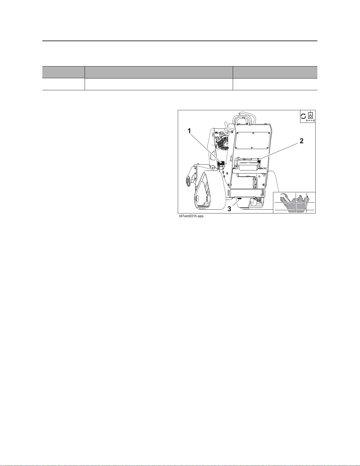
Service - 98 C16x/C24x/C30x Operator’s Manual
500 Hour Service
500 Hour Service
Location Task Notes
Trencher Change hydraulic fluid and filter THF
Change Hydraulic Fluid and Filter
Change hydraulic fluid and filter every 500 hours.
1. Place an appropriate container below
2. To drain fluid: remove drain plug (3).
3. Remove and clean strainer.
4. Install strainer.
hydraulic drain (3).
5. Change filter (2).
6. To fill hydraulic reservoir, add fluid at fill
cap (1) until correct level on sight glass is
reached.

C16x/C24x/C30x Operator’s Manual Service - 99
As Needed
As Needed
Location Task Notes
Engine Replace in-line fuel filter
Adjust wheel track tension
Check battery
Replace In-Line Fuel Filter
See engine service manual for procedure.
Adjust Wheel Track Tension
Adjust wheel track tension on both sides when
tracks are replaced.
To adjust:
1. Park machine on level and firm ground.
2. Lay straight edge on top of track, spanning
from sprocket to front idler roller.
3. Tighten bolt(2):
• Loosen jam nut (1).
• Turn bolt (2) counterclockwise until
distance between track and straight edge
is 1/4” (6 mm).
• Tighten jam nut (1).
To test:
Drive forward one track length and check tension
with straight edge:
• If tension is too loose, tighten bolt (2).
• If tension is too tight, loosen bolt (2).
 Loading...