

Page 1
All Terrain Air Hammer
Attachment Operator’s Manual
Publication number: ID0273478; page 1 of 11
Foreword
This guide is an important part of your attachment. It
provides safety, operation, parts, and maintenance
information to help you use and maintain your Ditch
Witch equipment.
Read this manual and the unit operator’s manual before
using your attachment. Keep it with the equipment at all
times for future reference. If you sell your equipment, be
sure to give this manual to the new owner.
If you need a replacement copy, contact your Ditch Witch
dealer. If you need assistance in locating a dealer, visit
our website at www.ditchwitch.com or write to the
following address:
The Charles Machine Works, Inc.
Attn: Marketing Department
PO Box 66
Perry, OK 73077-0066
USA
The descriptions and specifications in this manual are
subject to change without notice. The Charles Machine
Works, Inc. reserves the right to improve equipment.
Some product improvements may have taken place after
this manual was published. For the latest information on
Ditch Witch equipment, see your Ditch Witch dealer.
Thank you for buying and using Ditch Witch equipment.
Safety
• Read and follow all safety precautions.
• Contact One-Call (888-258-0808) or your local utility company.
Have all underground lines and cable located and marked before
operating equipment. Know appropriate actions to take in case
you damage a utility. If you damage a utility, contact utility
company.
• Mark jobsite clearly and keep spectators away.
• Wear personal protective equipment. Do not wear jewelry or loose
clothing that can catch on controls.
• Use equipment carefully. Stop operation and investigate anything
that does not look or feel right.
• Contact your Ditch Witch dealer if you have any question about
operation, maintenance, or equipment use.
Jobsite hazards could cause death or
serious injury. Use correct equipment and work
methods. Use and maintain proper safety
equipment.
Improper control function could cause death or
serious injury. If control does not work as described in
instructions, stop machine and have it serviced.
Incorrect procedures could result in death, injury,
or property damage. Learn to use equipment correctly.
Moving parts could cut off hand or foot.
Stay away.
All Terrain Air Hammer Attachment
Operation and Parts Manual
Issue number 2.0 OM-1/12
Part number ID0273478
Copyright 2011, 2012
by The Charles Machine Works, Inc.
Ditch Witch, CMW, and Jet Trac are registered
trademarks of The Charles Machine Works,
Inc.
cause death or serious injury. Know location of lines and
Electrical shock. Contacting electrical lines will
stay away.
Crushing weight could cause death or
serious injury. Use proper procedures and
equipment or stay away.
Flying objects may cause injury. Wear hard hat
and safety glasses.
Exposure to high noise levels may cause hearing
loss. Wear hearing protection.
Pressurized fluid or air could pierce
skin and cause injury or death. Stay away.
Hot parts may cause burns. Do not touch until
cool.
Moving tools will kill or injure. Shut off drill string
power when anyone can be struck by moving or thrown
tools. Never use pipe wrenches on drill string.
CMW
®
Page 2
All Terrain Air Hammer
Attachment Operator’s Manual
Publication number: ID0273478; page 2 of 11
Improper handling or use of chemicals may
result in illness, injury, or equipment damage. Follow
instructions on labels and in material safety data sheets
(MSDS).
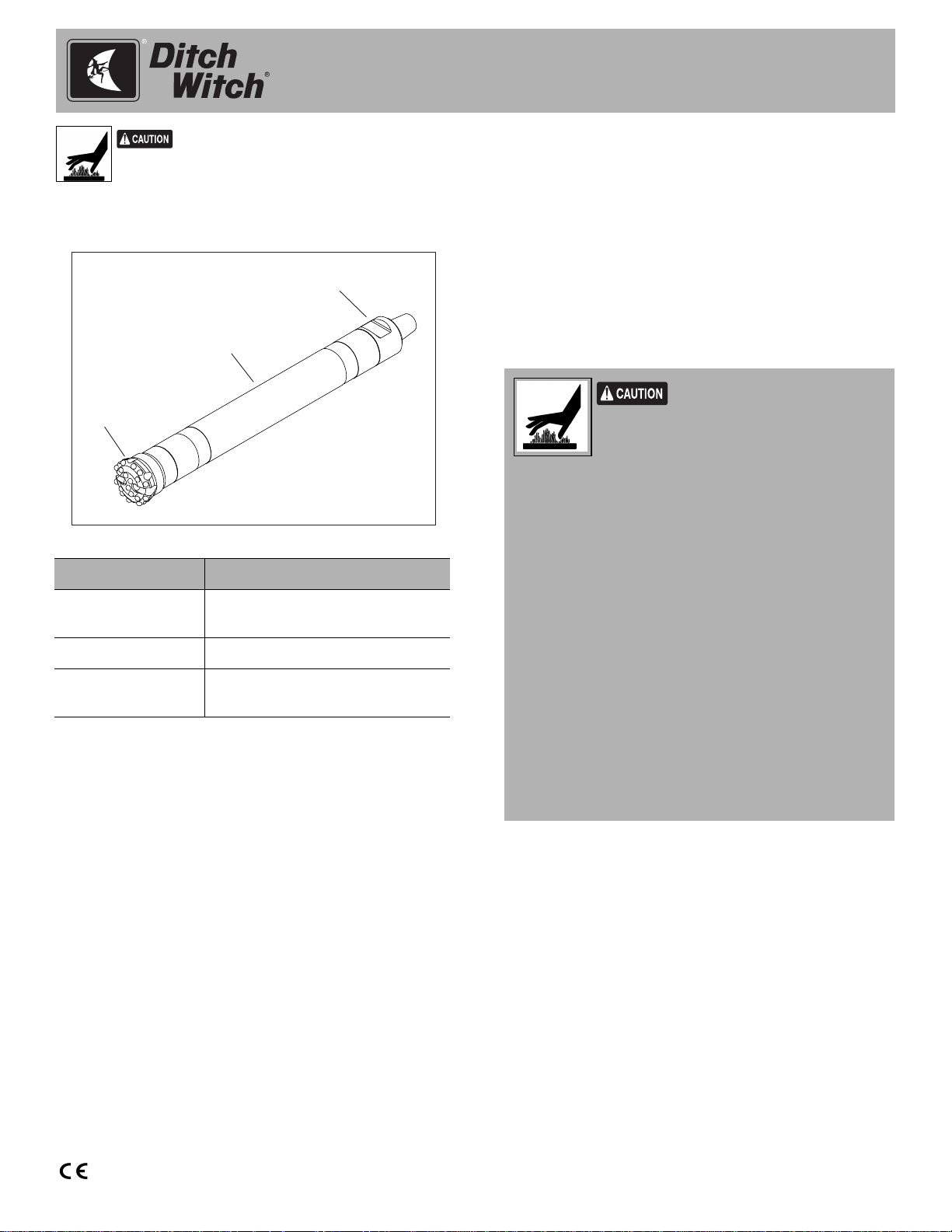
Overview
3
2
1
a38om001t.eps
Component Description
1. Bit holds cutting teeth that chip rock
at impact
2. Hammer houses the percussion piston
3. Hydrocyclone separates pressurized air from
water in foam mix
The All Terrain Air Hammer is designed for use on
directional drills in hard rock applications. The air
hammer uses air pressure to create percussive force,
which drives cutting inserts into rock. After the “drive” air
has produced impact, it is expelled as “return” air that
removes cuttings. Foam mix injected into the bore
through the drill string is used to suppress dust and clean
the bore.
Prepare Foam Mix
The manufacturer recommends the use of Baroid QuikFoam® foaming agent (p/n 255-1023) to improve holecleaning capability of the airstream and reduce dust
during drilling.
As a general guideline, use 0.25-1 gal (0.9-3.8 L) of foam
agent for each 100 gal (379 L) of water.
For more information, see the instructions for foam
drilling system mixtures included with the foaming agent
or contact your Ditch Witch dealer.
Improper handling or use of
chemicals may result in illness, injury, or
equipment damage. Follow instructions
on labels and in material safety data
sheets (MSDS).
To help avoid injury:
• Flammable.
• Do not allow QuikFoam to enter sewer, water way,
or low area. Contain all product and dispose
properly.
• Quik-Foam may cause eye, skin, and respiratory
irritation. May cause headache, dizziness, and
other central nervous system affects. May be
absorbed through the skin. May be harmful if
swallowed. Repeated overexposure may cause
liver and kidney effects.
• Use appropriate protective equipment.
• See Quik-Foam MSDS (available on
www.ditchwitch.com) for more information.
CMW
®
Page 3
All Terrain Air Hammer
Attachment Operator’s Manual
Publication number: ID0273478; page 3 of 11
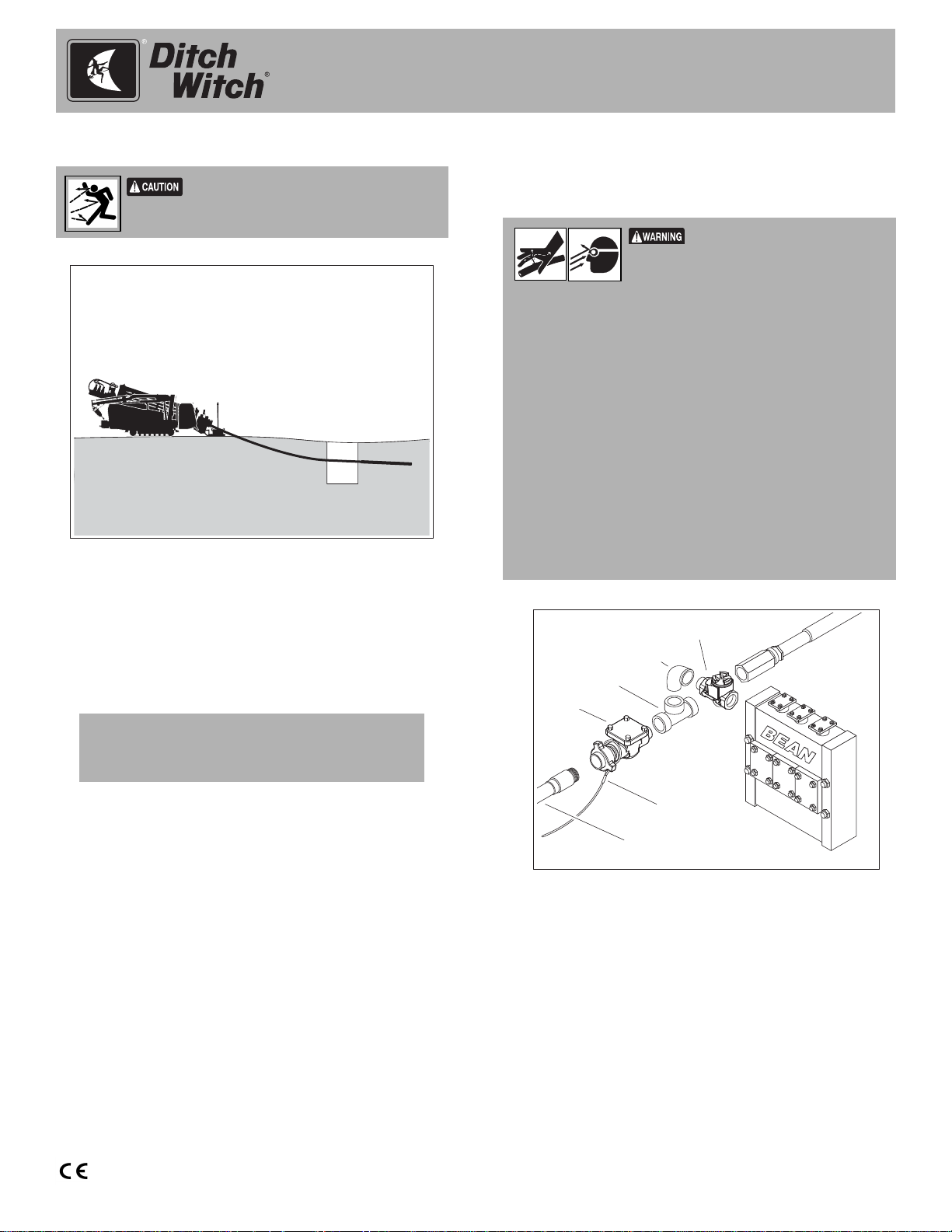
Prepare Entry Point
Flying objects may cause injury. Wear hard
hat and safety glasses.
a38om005t.eps
1. Dig an entry pit approximately 10-15 ft (3-4.5 m) in
front of the drilling unit to collect spoils and foam
blowback. The pit should be approximately 6 ft (1.8
m) long, 3 ft (0.9 m) wide, and deep enough to
expose the drill string.
2. Drill into the ground, through the entry pit, and
continue bore.
IMPORTANT: It may be necessary to cover the
entry pit with a sheet of plywood or other
durable material to contain blowback material.
Connect Air Adaptor
To operate the air hammer, modify the drilling fluid pump
onboard the drilling unit to provide air flow to the hammer.
Pressurized fluid or air could pierce
skin and cause injury or death. Stay away.
To help avoid injury:
• Escaping pressurized fluid or air can cause injury or pierce skin
and poison.
• Before disconnecting a hydraulic line or pressurized air line,
turn engine off and operate all controls to relieve pressure.
Lower, block, or support any raised component with a hoist.
Cover connection with heavy cloth and loosen connector nut
slightly to relieve residual pressure.
• Before using system, check that all connections are tight and
all lines are undamaged.
• Fluid and air leaks can be hard to detect. Use a piece of
cardboard or wood, rather than hands, to search for leaks.
• Wear protective clothing, including gloves and eye protection.
• If you are injured, seek immediate medical attention from a
doctor familiar with this type of injury.
4
3
2
1
6
5
a38om003t.eps
Note: See parts pages for a complete list of parts.
1. Disconnect washwand from drilling fluid pump inlet.
2. Install check valve (4) in drilling fluid pump inlet.
3. Connect elbow and T-fitting (3, 2) to check valve.
4. Connect air adaptor (1) to rear of T-fitting.
5. Connect whip check cable (6) and air compressor
hose (5) to air adaptor.
CMW
®
Page 4
All Terrain Air Hammer
Attachment Operator’s Manual
Publication number: ID0273478; page 4 of 11
Connect Air Hammer
IMPORTANT: The procedures below require the use of
a Hydratong wrench to tighten connections. See “Use
Hydratong Wrenches” on page 4.
Install Bit
1. Lubricate bit splines and chuck threads with copper
or zinc based tool joint compound.
2. Slide chuck over bit splines and secure with retaining
rings.
3. Thread bit/chuck assembly into hammer housing.
4. Use appropriate bit ring and chrome pins included
with air hammer with Hydratong wrench. Place chain
tongs no less than 6.5” (152 mm) and no more than
17” (432 mm) from chuck.
NOTICE: Using wrench tongs to grip the
hammer casing in the wrong location can
damage threads or distort the casing.
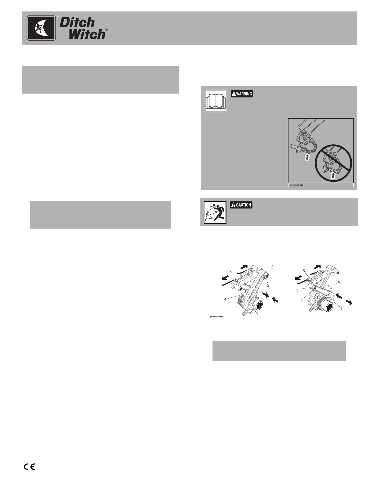
Use Hydratong Wrenches
To attach or remove downhole tools, use the Hydratong
wrenches to join or break the joint.
Incorrect procedures could result in death,
injury, or property damage. Learn to use equipment
correctly.
To help avoid injury:
• Ensure only chain tongs and
chain are in contact with pipe
(shown) and that chain is
correctly wrapped. Do not
use Hydratong with chain
bushing pin touching pipe
(shown).
• Stand away from the
Hydratong when using it.
Moving tools will kill or injure. Shut off drill
string power when anyone can be struck by moving or
thrown tools. Never use pipe wrenches on drill string.
5. Tighten to 6000 ft•lb (8135 N•m).
Assemble Drill String
1. Connect air hammer to Rockmaster beacon housing
using Hydratong wrench and air hammer wrench
insert.
2. Follow the instructions in your drilling unit operator’s
manual to prepare and calibrate the beacon before
drilling.
3. Connect air hammer/beacon assembly to drill string.
1. To join, apply tool joint compound to threads and
hand tighten joint.
2. Attach Hydratong in either the join or break position.
Join Break
IMPORTANT: Ensure arms are crossed
before using wrench.
• Attach chain tongs (1) to both sides of joint.
Place tongs as close to joint as possible.
• Remove snapper pins (2) from slide pins (3), and
insert slide pins into wrench handles (4).
• Attach each end of hydraulic cylinder (5) to slide
pins and insert snapper pins.
3. Remove all slack from wrench and joint.
CMW
®
Page 5

All Terrain Air Hammer
Attachment Operator’s Manual
Publication number: ID0273478; page 5 of 11
4. To join, scribe
straight line across
joint on both sides
of separating line
(A).
5. To join, scribe
second line (B) on
A
B
A
B
AA
moveable side of
joint in the opposite
direction of
tightening action.
j07om071h.eps
Refer to table for
correct dimension.
6. Connect Hydratong
power pack.
• Attach hoses
from power
pack to
cylinder.
• Attach leads (4)
to 12V battery.
7. To tighten or loosen
joint, move shuttle valve handle (2) toward gauge (3)
and press power switch (1).
8. To reposition chain tongs and continue tightening or
loosening joint, move handle away from gauge, then
back toward gauge, and then press power switch.
9. Monitor gauge and refer to decal to achieve
approximately 4000 ft•lb (5420 N•m) of torque. Then
tighten joint until second line (B) meets first (A).
Operate Air Hammer
Wear hearing and eye
protection when operating air
hammer.
To start hammering, turn on the drill fluid pump. Air will
enter the drill string.
IMPORTANT: The air hammer requires resistance to
fire. If the bit is not next to hard rock air will simply flow
through the hammer without triggering percussion.
Monitor Gauges
Drill Fluid
Maintain drill fluid flow at 2-10 gpm (7.5-38 L/min)
depending on the hole size, rate of penetration, and type
of material being drilled. The ideal drill fluid flow produces
a thin foam that allows cuttings to be cleared from the
hole without sticking to drill pipe.
Rotation
The correct rotation speed produces the best penetration
rate, the longest drill bit life, and smooth operation.
1. For a 6.5” (165 mm) bit with spherical inserts, begin
with inner rotation of 25 rpm.
2. Adjust rotation until penetration is approximately
3/8-5/8” (9.5-116 mm) per revolution.
IMPORTANT: Gauge gives an estimate of
torque. Use scribe line to get exact torque.
10. Move handle to center (neutral) position to relieve
pressure.
11. Disconnect hoses and remove Hydratong
components.
Thrust
Maintain thrust at about 3200 lbf (14 kN) when operating
at maximum power. This is theoretically 600-800 psi (4055 bar) as measured by the thrust pressure gauge on the
drilling unit.
Note: Some operators increase thrust until rotation
pressure begins to pulse, then reduce thrust slightly until
rotation is smooth.
CMW
®
Page 6

All Terrain Air Hammer
Attachment Operator’s Manual
Publication number: ID0273478; page 6 of 11
Monitor Cuttings
Monitor spoils leaving the bore at the entry pit. If cuttings
are not clearing the hole, a different drill fluid mixture
might be needed to seal the bore.
Set Cruise Control
Once bore is established, set cruise control. (See drilling
unit operator’s manual for instructions.)
Add Pipe
Pressurized fluid or air could
pierce skin and cause injury or death.
Stay away.
Drill string contains pressurized air and water. Before
breaking joints to add pipe, stop drilling fluid flow and wait
for the reading on the drill fluid pressure gauge to drop.
Storage
If the air hammer will not be used for 48 hours after
drilling, coat the inside of the hammer with oil.
To add oil, choose one of the methods below:
• If the hammer is connected to the drill string, turn off
drilling fluid supply to the drilling unit. Operate
hammer to push remaining fluid out of hammer.
Break joint and pour 1 pint (0.5 L) of oil into the last
drill pipe. Operate hammer to blow oil through the
hammer components.
• If the hammer is not connected to the drill string,
remove bit and pour oil into the hammer housing.
Rotate hammer housing so that oil coats the inside.
Store air hammer in a clean, dry place. Cover air hammer
to keep it clean. For long-term storage, place tool
vertically.
Service
Each Use
Inspect Hydrocyclone
Inspect hydrocyclone after each bore to ensure that
backhead ports are passing air.
10-Hour
Grease Rockmaster Beacon Housing
Install zerk and pump multi-purpose grease into lube
point at the beginning of each bore and every 10 hours of
operation.
Every 15, 000 ft (4575 m)
Check Air Hammer
Disassemble air hammer and inspect inner components
every 15, 000 ft (4575 m) of use. Replace components as
needed and reassemble tool.
CMW
®
Page 7

Disassemble
16
2
a38om006t.eps
1. Break joint at bit (2). Do not remove bit and chuck.
2. Break backhead joint and remove backhead (16).
All Terrain Air Hammer
Attachment Operator’s Manual
Publication number: ID0273478; page 7 of 11
a38om008t.eps
5. Remove valve cap/valve/distributor/air cylinder
assembly (shown).
15
14
13
a38om007t.eps
3. Remove dart valve (15) and spring (14) assembly.
4. Remove make-up spacer (13).
8
a38om023t.eps
6. Remove bit/chuck assembly from casing (8).
8
4
3
2
1
a38om021t.eps
7. Disassemble bit (1) from chuck (2) by removing oring (4) from around bit lock (3).
CMW
®
Page 8

All Terrain Air Hammer
Attachment Operator’s Manual
Publication number: ID0273478; page 8 of 11
or serious injury. Use proper procedures and
equipment or stay away.
To help avoid injury:
• Use proper lifting equipment and lifting procedures.
• Use team lifting when necessary.
Crushing weight could cause death
7
6
5
a38om010t.eps
5. bit bearing
6. lock ring
7. piston
a38om012t.eps
10. Slam remaining parts of valve/distributor/cylinder
assembly on piston (7) until valve and distributor
8
separate from the inner air cylinder.
Assemble
8. Remove bit bearing/lock ring/piston assembly by
slamming casing (8) on a block of wood.
Disassemble parts as shown.
a38om011t.eps
9. Using a pry bar or screwdriver, pry up on the valve
cap where shown on both sides to remove.
12
11
a38om013t.eps
1. Press valve (11) firmly into valve cap (12).
10
9
a38om014t.eps
2. Press distributor (10) firmly into inner air cylinder (9).
CMW
®
Page 9

a38om015t.eps
3. Press valve assembly firmly into distributor/cylinder
assembly.
All Terrain Air Hammer
Attachment Operator’s Manual
Publication number: ID0273478; page 9 of 11
8
6
5
a38om019t.eps
5. Click lock ring (6) into place and then install bit
bearing (5) into casing (8). Use a bar to tap bearing
until it is seated. Use bit lock as spacing guide.
a38om016t.eps
Verify valve has approximately 0.05 in (1.3 mm) of
free movement, as shown.
8
7
a38om018t.eps
4. Insert piston assembly (7) into casing (8).
8
a38om017t.eps
6. Slide valve assembly into opposite end of casing (8).
7. Install make-up spacer, spring, and dart valve.
16
8
a38om020t.eps
8. Install backhead (16) into casing (8).
9. Install bit. “Change Air Hammer Bits” on page 10
CMW
®
Page 10

All Terrain Air Hammer
Attachment Operator’s Manual
Publication number: ID0273478; page 10 of 11
As Needed
Change Air Hammer Bits
8
4
3
2
1
a38om021t.eps
Change air hammer bits whenever inserts are worn.
To remove:
1. Break joint at chuck and remove bit/chuck assembly.
2. Remove o-ring (4) from bit lock (3).
3. Remove bit (1) from chuck (2).
To install:
Specifications
L3
D
L2
L
a38om004t.eps
General U.S. Metric
Standard drill pipe connection 3.5 in API Reg Pin
Shank style QL 60
D Outside diameter 5.4 in 138,2 mm
L1 Length without bit shoulder to
shoulder
L2 Length with bit extended 49.5 in 1256,3 mm
L3 Length with bit retracted 48.1 in 1220,7 mm
44.6 in 1131,8 mm
1. Slide bit (1) into chuck (2).
2. Assemble bit lock (3) over end of bit and secure with
o-ring (4).
3. Install bit/chuck assembly into casing (8) and tighten
to 6000 ft•lb (8124 N•m).
Weight without bit 200 lb 90,9 kg
Backhead across flats 2x4 AF
Recommended air pressure 350 psi 24,1 bar
Make-up torque 6000 ft•lb 8124,0 N•m
Recommended fluid flow 3-4 gpm
Air volume 973 cfm 458 L/sec
Blows per minute 1770 1770
CMW
®
Page 11

All Terrain Air Hammer
Attachment Operator’s Manual
Publication number: ID0273478; page 11 of 11
Support
Procedure
Notify your dealer immediately of any malfunction or
failure of Ditch Witch equipment.
Always give model, serial number, and approximate date
of your equipment purchase. This information should be
recorded and placed on file by the owner at the time of
purchase.
Return damaged parts to dealer for inspection and
warranty consideration if in warranty time frame.
Order genuine Ditch Witch replacement or repair parts
from your authorized Ditch Witch dealer. Use of another
manufacturer's parts may void warranty consideration.
Resources
Publications
Contact your Ditch Witch dealer for publications and
videos covering safety, operation, service, and repair of
your equipment.
Ditch Witch Training
For information about on-site, individualized training,
contact your Ditch Witch dealer.
Warranty
Ditch Witch Equipment and Replacement Parts
Limited Warranty Policy
Subject to the limitation and exclusions herein, free replacement parts
will be provided at any authorized Ditch Witch dealership for any Ditch
Witch equipment or parts manufactured by The Charles Machine
Works, Inc. (CMW) that fail due to a defect in material or workmanship
within one (1) year of first commercial use (Exception: 2 years for all SK
attachments). Free labor will be provided at any authorized Ditch Witch
dealership for installation of parts under this warranty during the first
year following “initial commercial” use of the serial-numbered Ditch
Witch equipment on which it is installed. The customer is responsible
for transporting their equipment to an authorized Ditch Witch dealership
for all warranty work.
Exclusions from Product Warranty
• All incidental or consequential damages.
• All defects, damages, or injuries caused by misuse, abuse,
improper installation, alteration, neglect, or uses other than those
for which products were intended.
• All defects, damages, or injuries caused by improper training,
operation, or servicing of products in a manner inconsistent with
manufacturer’s recommendations.
• All engines and engine accessories (these are covered by original
manufacturer’s warranty).
• Tires, belts, and other parts which may be subject to another
manufacturer’s warranty (such warranty will be available to
purchaser).
• ALL IMPLIED WARRANTIES NOT EXPRESSLY STATED
HEREIN, INCLUDING ANY WARRANTY OF FITNESS FOR A
PARTICULAR PURPOSE AND MERCHANTABILITY.
IF THE PRODUCTS ARE PURCHASED FOR COMMERCIAL
PURPOSES, AS DEFINED BY THE UNIFORM COMMERCIAL CODE,
THEN THERE ARE NO WARRANTIES WHICH EXTEND BEYOND
THE FACE HEREOF AND THERE ARE NO IMPLIED WARRANTIES
OF ANY KIND WHICH EXTEND TO A COMMERCIAL BUYER. ALL
OTHER PROVISIONS OF THIS LIMITED WARRANTY APPLY
INCLUDING THE DUTIES IMPOSED.
Ditch Witch products have been tested to deliver acceptable
performance in most conditions. This does not imply they will deliver
acceptable performance in all conditions. Therefore, to assure
suitability, products should be operated under anticipated working
conditions prior to purchase.
Defects will be determined by an inspection within thirty (30) days of the
date of failure of the product or part by CMW or its authorized dealer.
CMW will provide the location of its inspection facilities or its nearest
authorized dealer upon inquiry. CMW reserves the right to supply
remanufactured replacements parts under this warranty as it deems
appropriate.
Extended warranties are available upon request from your local Ditch
Witch dealer or CMW.
Some states do not allow exclusion or limitation of incidental or
consequential damages, so above limitation of exclusion may not apply.
Further, some states do not allow exclusion of or limitation of how long
an implied warranty lasts, so the above limitation may not apply. This
limited warranty gives product owner specific legal rights and the
product owner may also have other rights which vary from state to
state.
For information regarding this limited warranty, contact CMW’s Product
Support department, P.O. Box 66, Perry, OK 73077-0066, or contact
your local Ditch Witch dealer.
First version: 1/91; Latest version: 7/05
CMW
®
 Loading...