

Page 1
© 2005
Instruction Manual
TCD 2012 L04/06 4V
TCD 2013 L04/06 4V
Page 2

© 2005
Read and observe the information in this
instruction manual. You will avoid accidents,
retain the manufacturer’s warranty and have
a fully functional, ready to use engine at your
disposal.
z This engine is exclusively for the purpose
according to the scope of delivery - defined
and built by the equipment manufacturer (use
for the intended purpose) Any use above and
beyond this is considered improper use. The
manufacturer will not be liable for damages
resulting from this. The user will bear the sole
risk in this case.
z Use for the intended purpose also includes
observance of the operating, maintenance
and repair instructions specified by the
manufacturer. The engine may only be used,
maintained and repaired by persons who are
familiar with it and instructed in the dangers.
z Maintenance/cleaning work on the engine
may only be carried out when the engine is not
running and has cooled down.
When doing this, make sure that the electrical
system is switched off (remove ignition key).
The specifications for accident prevention
with electrical systems (e.g. VDE-0100/-0101/
-0104/-0105 Electrical protective measures
against dangerous touch voltages) must be
observed.
Cover all electrical components tightly when
cleaning with liquids.
z Do not work on the fuel system while the
engine is running - Danger to life.
- Wait (1 minute) for the engine to come to a
standstill (pressure release), as system is
under high pressure: there is a - Danger to
life.
During the first trial run do not stand in the
danger area of the engine (danger due to high
pressure of leaks) - Danger to life.
- In case of leaks immediately contact the
workshop.
- When working on the fuel system
ensure that the engine is not unintentionally
started during repairs. Danger to life.
z The pertinent rules for the prevention of
accidents and other generally recognised
safety and industrial medicine rules must be
observed.
z When the engine is running there is a danger
of injury caused by:
- rotating / hot components
- engines with extraneous ignition
- ignition systems (high electrical voltage)
Contact must be avoided!
z The manufacturer will not be liable for damages
resulting from unauthorised modification to the
engine.
Equally, manipulations to the injection and control
system can affect the engine’s performance
and the exhaust characteristics. Compliance
with environmental regulations will no longer
be guaranteed in this case.
z Do not alter, obstruct or block the area of the
cool air supply to the fan.
The manufacturer will accept no liability for
damages resulting from this.
z Only DEUTZ original parts may be used when
carrying out maintenance/repair work on the
engine. These have been designed especially
for your engine and ensure a trouble-free
operation.
Failure to observe this will lead to voiding of the
warranty!
Page 3

© 2005
Instruction Manual
TCD 2012 L04/06 4V
TCD 2013 L04/06 4V
0312 2443 en
Engine number:
Please enter the engine number here. This
will simplify the handling of customer service,
repair and spare parts queries (see Section
2.1).
Illustrations and data in this instruction manual
are subject to technical changes in the course
of improvements to the engines. Reprinting
and reproductions of any kind, even in part,
require our written permission.
Page 4

© 2005
Foreword
Dear customer,
The liquid-cooled engines made by DEUTZ are
developed for a wide variety of applications.
An extensive range of variants ensures that
the respective special requirements are met.
Your engine is equipped according to the
installation, i.e. not all the parts and
components described in this instruction
manual are installed on your engine.
We have done our best to clearly identify the
differences, so that you can easily find the
operating, maintenance and repair
instructions relevant to your engine.
Please read these instructions before you
start your engine and observe the operating
and maintenance instructions.
We are at your service for any questions you
may have in this matter.
Your
DEUTZ AG
Page 5

© 2005
Contents
1. General
2. Engine description
2.1 Engine type
2.1.1 Company plate
2.1.2 Location of company plate
2.1.3 Engine number
2.1.4 Cylinder numbering
2.2.1 Operation side
TDC 2012 L04 4V
2.2 Engine diagrams
2.2.2 Starter side
TDC 2012 L04 4V
2.2.3 Operation side
TDC 2012 L06 4V
2.2.4 Starter side
TDC 2012 L06 4V
2.2.5 Operation side
TDC 2013 L06 4V
2.2.6 Starter side
TDC 2013 L06 4V
2.2.7 Operation side
Agri Power
2.2.8 Starter side
Agri Power
2.2 Engine diagrams
2.3.1 Lube oil diagram
TCD 2013 L06 4V (example)
2.4 Fuel circuit
2.4.1 Fuel diagram
2.5 Coolant circuit
2.5.1 Coolant diagram
2.5.2 Exhaust gas recirculation diagram
2.6 Electrics
2.6.1 Electrical cable connections for
monitoring
3. Operation
3.1 Initial commisioning
3.1.1 Filling engine oil
3.1.2 Filling fuel
3.1.3 Filling / bleeding cooling system
3.1.4 Other preparations
3.2 Starting
3.2.1 Electrical starting
3.3 Operation monitoring
3.3.1 Engine oil pressure
3.3.2 Coolant temperature
3.3.3 Coolant level
3.3.4 Lube oil level
3.4 Shutting down
3.4.1 Electrical shutdown
3.5 Operating conditions
3.5.1 Winter operation
3.5.2 High ambient temperature,
high altitude
4. Operating substances
4.1 Lube oil
4.1.1 Quality
4.1.2 Viscosity
4.2 Fuel
4.2.1 Quality
4.2.2 Winter fuel
4.3 Coolant
4.3.1 Water quality for coolant
4.3.2 Coolant preparation
4.3.3 Cooling system preservative
5. Maintenance
5.1 Maintenance schedule
5.2 Maintenance diagram
5.3 Maintenance work carried out
6. Care and maintenance
work
6.1 Lubrication system
6.1.1 Oil change intervals
6.1.2 Checking oil level, changing engine oil
6.1.3 Changing oil filter insert
6.1.4 Cleaning / changing oil filter (cup) fehlt
6.2 Fuel system
6.2.1 Changing fuel filter
6.2.2 Cleaning / changing fuel filter (cup)
6.2.3 Changing / bleeding fuel pre-filter, filter
insert
6.3 Cooling system
6.3.1 Cleaning intervals
6.3.2 Cleaning cooling system
6.3.3
Emptying / filling / bleeding cooling
isystem
6.4 Combustion air filter
6.4.1 Cleaning intervals
6.4.2 Emptying cyclone pre-separator
6.4.3 Dry air filter
6.5 Belt drive
6.5.1 Checking V-rib belt
6.5.2 Changing V-rib belt
6.5.3 Checking wear limit of v-rib belt fehlt
6.6 Setting work
6.6.1 Checking valve clearance, setting if
necessary
6.6.2 Checking control piston clearance at
engine brake, setting if necessary
6.7 Add-on parts
6.7.1 Battery
6.7.2 Three-phase current generator
6.7.3 Transportation suspension
Page 6

© 2005
7. Faults, causes and remedies
7.1 Fault table
7.2 Engine management
7.2.1 Engine protection function of the
electronic engine controller EMR3
7.2.2 Using the diagnosis button
7.2.3 Table of fault blink codes
8. Engine corrosion protection
8.1 Corrosion protection
9. Technical data
9.1 Engine and setting data
9.2 Screw tightening torques
9.3 Tools
10. Service
Contents
Page 7
© 2005
Page 8
1
© 2005
General
DEUTZ engines Maintenance and care
This symbol is used for all safety
instructions which, if not
observed, present a direct
danger to life and limb for the
person involved. Observe these
carefully. Also pass on the
safety instructions to your operating
personnel. Furthermore, the legislation for
„general regulations for safety and the
prevention of accidents“ must be observed.
Service
Please consult one of our service
representatives responsible for operating
faults and spare parts questions. Our trained
specialist personnel ensures fast,
professional repairs using original parts in
the event of damage.
The Technical Circulars listed in this operating
manual are obtainable from your DEUTZ
partner.
Please turn to the end of this manual for
further service information.
Take care when the engine is
running
Only carry out maintenance work or repairs
with the engine switched off. Ensure that the
engine cannot be started unintentionally danger of accidents!
Re-install any removed protective equipment
upon completion of the work.
Observe industrial safety regulations when
operating the engine in enclosed spaces or
underground.
When working on the running engine, work
clothing must be close fitting.
Only re-fuel with the engine switched off.
are decisive for whether the engine
satisfactorily meets the demands put on it.
Compliance with the prescribed maintenance
times and the careful execution of
maintenance and care work are therefore
essential. Difficult operating conditions
deviating from normal operation must be
observed especially.
Warning
Danger for component/engine.
Failure to comply can lead to
destruction of the component/
engine. Must be observed.
Danger
are the product of years of research and
development. The profound know-how
gained in connection with high quality
requirements is the guarantee for
manufacturing of engines with a long life,
high reliability and low fuel consumption.
Naturally the high requirements for protection
of the environment are also met.
Page 9

2
Engine description
© 2005
2.1 Engine type
2.2 Engine diagrams
2.3 Lube oil circuit
2.4 Fuel circuit
2.5 Coolant circuit
2.6 Electrics
Page 10
2
Engine description
© 2005
© 35 985 0
© 38 986 0
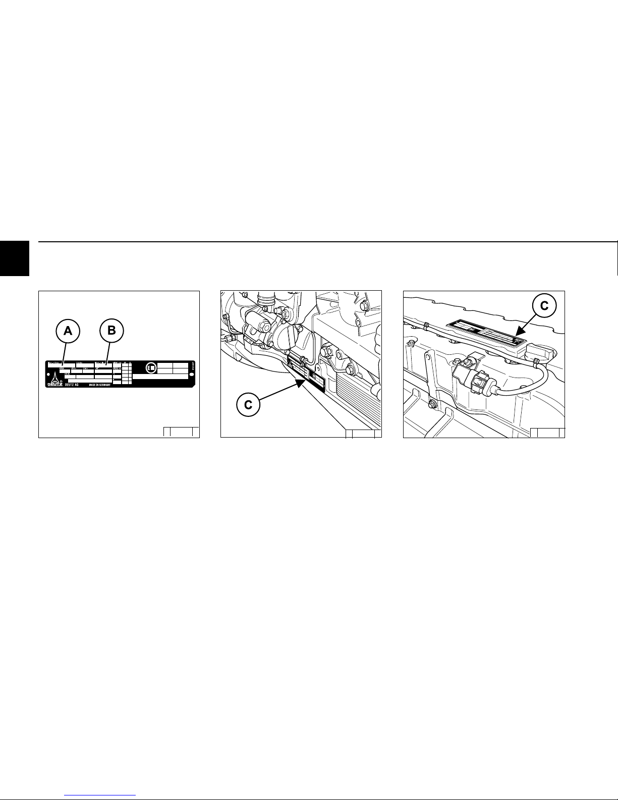
2.1 Engine type
2.1.1 Company plate
The engine type A, engine numberB and the
power data are stamped on the company plate.
The engine type and number must be stated
when purchasing spare parts.
2.1.2 Location of company plate
The company plate C is fixed on the crankcase.
© 38 987 0
Or company plate C is fixed on the cylinder head
cover.
Or both plates are attached.
Page 11
2
Engine description
© 2005
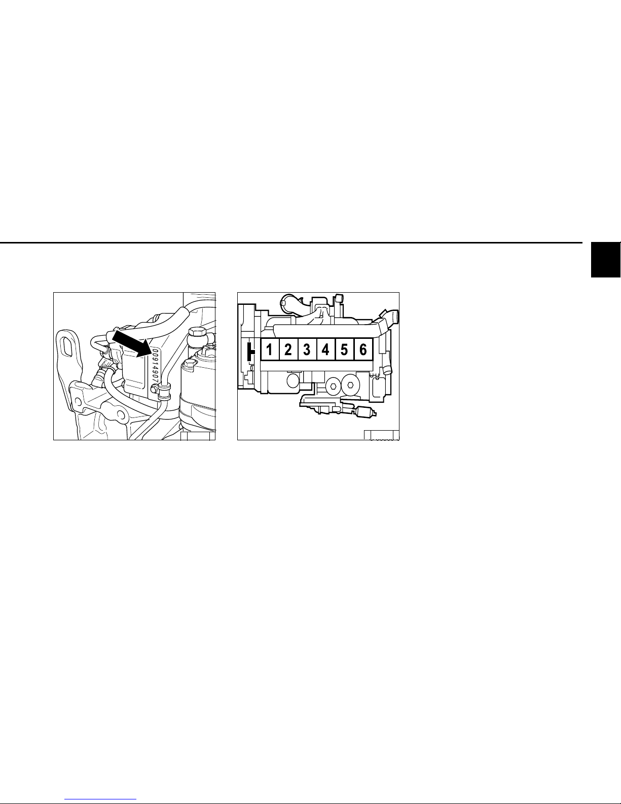
© 38 988 0
© 38989 0
2.1 Engine type
2.1.4 Cylinder numbering
The cylinders are counted consecutively, starting
from the flywheel.
2.1.3 Engine number
The engine number is stamped on the crankcase
(arrow) and on the company plate.
Page 12
2
Engine description
© 2005
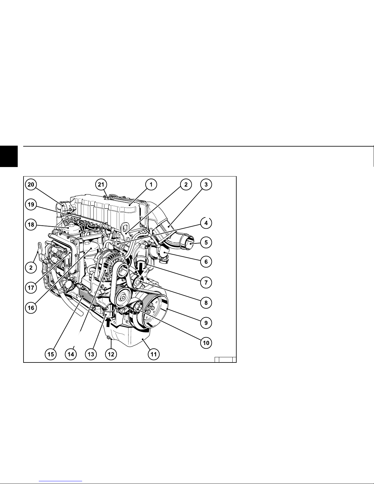
© 38 980 1
2.2 Engine diagrams
2.2.1 Operation side
TCD 2013 L04 4V
1 Cylinder head cover
2 Transportation eyelets
3 Heating flange
4 Cabin heater connection
5 Intake elbow to charge air cooler
6 Connection to air filter
7 Coolant outlet adapter
8 Deflection pulley
9 Belt pulley on crankshaft
10 Tension pulley
11 Oil tray
12 Oil drain screw
13 Coolant inlet adapter
14 Generator
15 Oil cooler
16 Exchangeable lube oil filter
17 Engine control unit
18 Exchangeable fuel filter
19 Rail with pressure reducing valve and pressure
sensor
20 Crankcase ventilation (open system)
21 Oil filler neck
Page 13
2
Engine description
© 2005
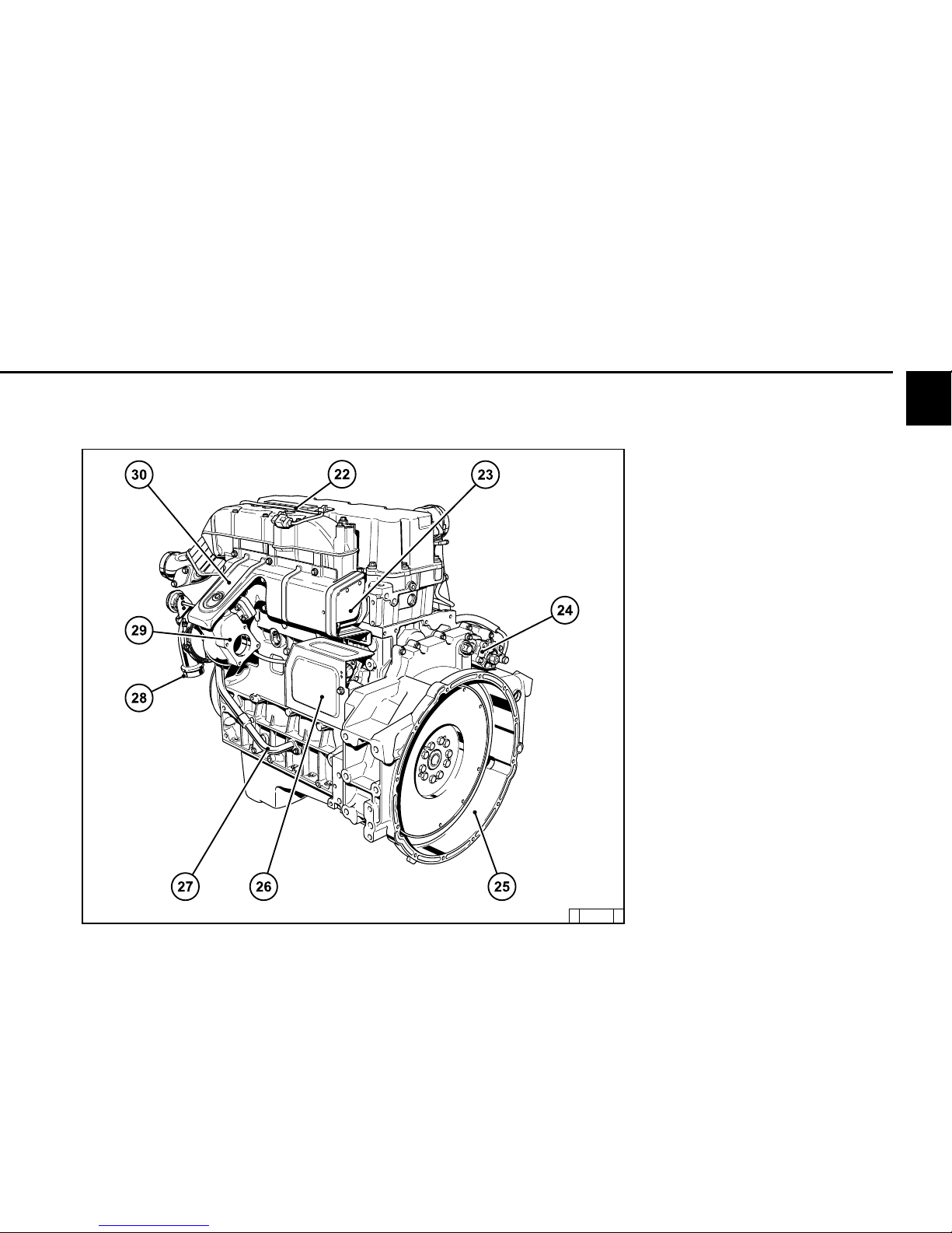
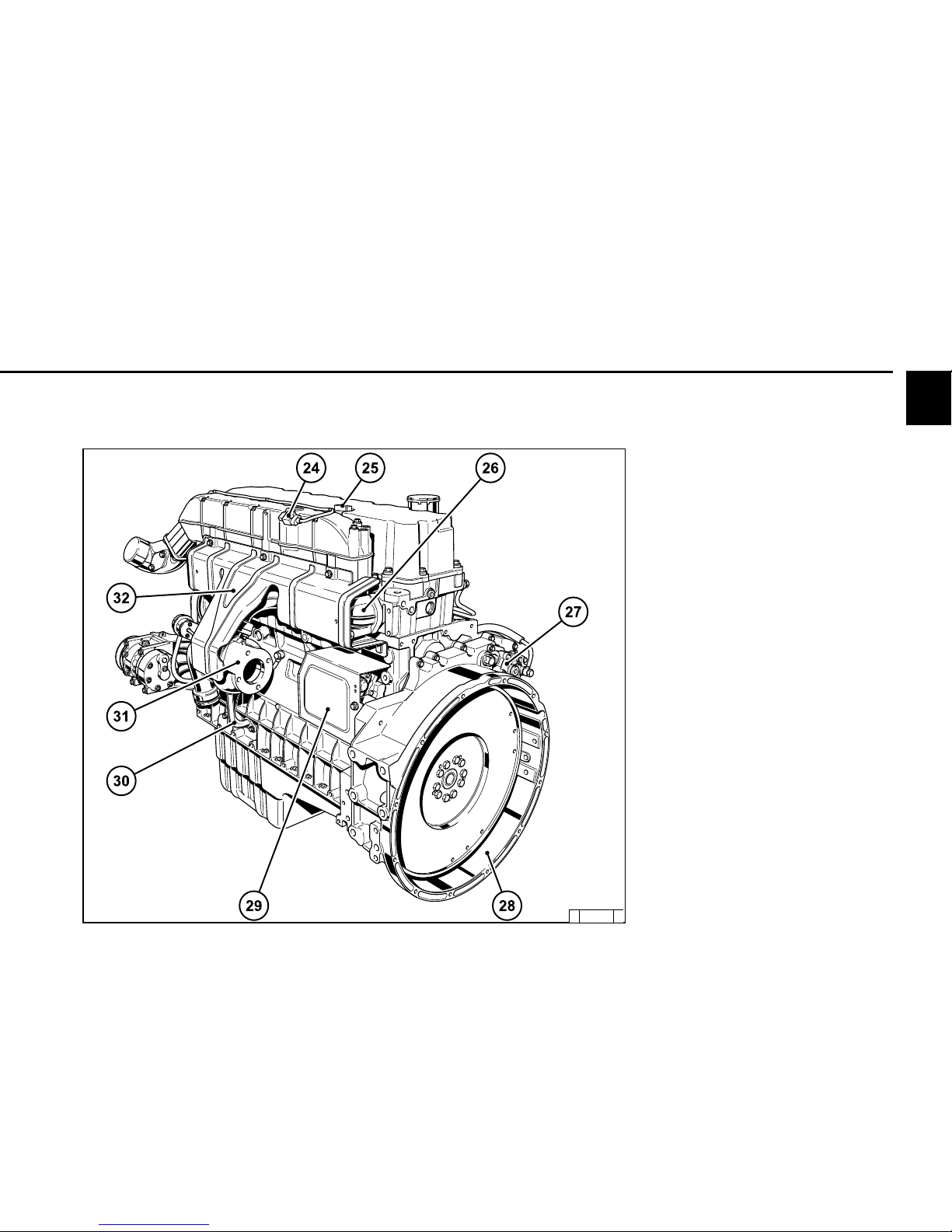
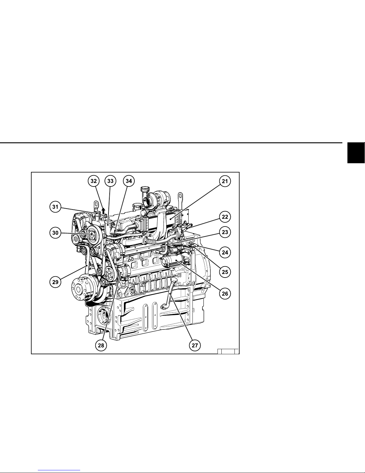
© 38 981 1
2.2 Engine diagrams
2.2.6 Starter side
TCD 2013 L04 4V
22 Charge air temperature line to transmitter
23 Exhaust manifold
24 Compressor (optional)
25 SAE housing
26 Starter cover
27 Oil return line from turbocharger
28 Inlet combustion air turbocharger
29 Turbocharger exhaust gas outlet
30 Screening plate (thermal protection)
Page 14
2
Engine description
© 2005
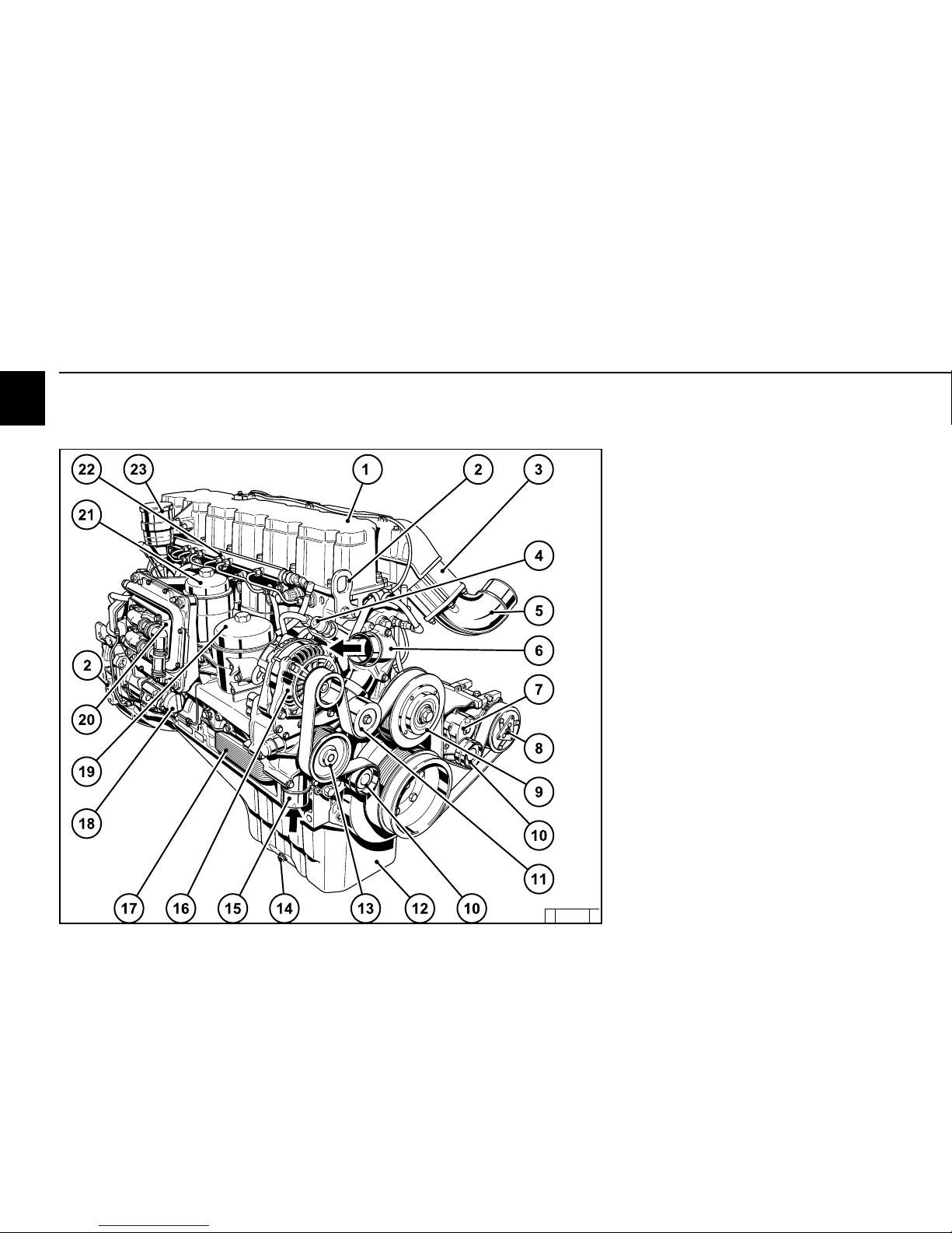
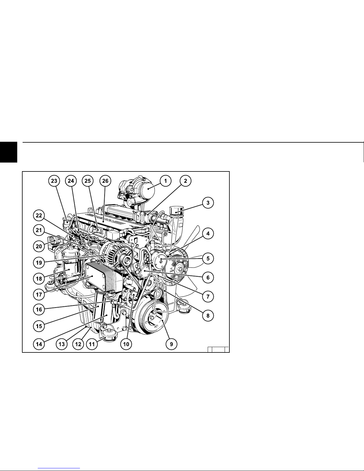
© 38 982 0
2.2 Engine diagrams
1 Cylinder head cover
2 Transportation eyelets
3 Heating flange
4 Cabin heater connection
5 Intake elbow from charge air cooler
6 Thermostat housing (coolant outlet)
7 Spring-loaded tension pulley
8 Compressor (optional)
9 Belt pulley for fan attachment
10 Tension pulley (s)
11 Deflection pulley
12 Oil tray
13 Belt pulley coolant pump
14 Oil drain screw
15 Coolant inlet adapter
16 Generator
17 Oil cooler
18 Hydraulic pump or compressor installation
(optional)
19 Exchangeable lube oil filter
20 Engine control unit with fuel cooling
21 Exchangeable fuel filter
22 Rail with pressure reducing valve and pressure
sensor
23 Crankcase ventilation (open system)
2.2.3 Operation side
TCD 2013 L06 4V
Page 15
2
Engine description
© 2005
© 38 983 0
2.2 Engine diagrams
2.2.4 Starter side
TDC 2013 L06 4V
2 4 P r e s s u r e a n d t e m p e r a t u r e t r a n s m i t t e r, c h a r g e a i r
25 Oil filler neck
26 Exhaust manifold
27 Compressor (optional)
28 SAE housing
29 Starter cover
30 Oil return line from turbocharger
31 Exhaust turbocharger
32 Screening plate (thermal protection).
Page 16
2
Engine description
© 2005
© 43 895 0
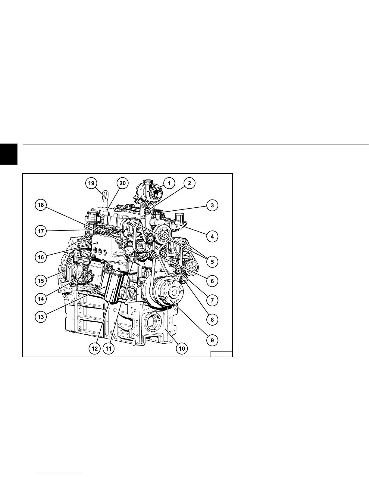
2.2 Engine diagrams
2.2.5 Operation side Agri Power
TCD 2012 L04 4V
1 Exhaust turbocharger
2 EGR exhaust gas recirculation
3 Intake elbow from charge air cooler
4 Coolant return from cooler
5 Coolant pump
6 Fuel supply pump
7 Spring-loaded tension pulley
8 V-rib belt
9 Belt pulley for drive
10 Coolant inlet adapter from cooler
11 Mounting foot (engine suspension)
12 Oil tray
13 Oil drain screw
14 Fuel filter
15 Lube oil filter
16 Fuel connection from tank
17 Lube oil cooler
18 Fuel pre-filter
19 Generator
20 Central connector
21 ECU ElectronicControl Unit
22 High-pressure pump
23 Crankcase ventilation
24 Rail with pressure reducing valve
25 Charge air sensor
26 Cylinder head cover
Page 17
2
Engine description
© 2005
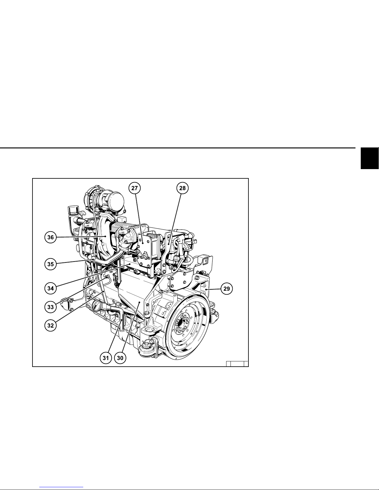
2.2 Engine diagrams
27 EGR exhaustgasRecirculation
Throttle lever for exhaustgasrecirculation
28 Transportation eyelets
29 SAE housing
30 Starter with cover
31 Lube oil filler neck
32 Lube oil return from turbocharger
33 Oil pressure pipe to turbocharger
34 Exhaust manifold
35 Cooling line to exhaust gas recirculation
system
36 Exhaust manifold
2.2.6 Operation side Agri Power
TCD 2012 L04 4V
© 43 896 0
Page 18
2
Engine description
© 2005
© 43 826 0
2.2 Engine diagrams
2.2.7 Operation side
TCD 2013 L06 4V Agri Power
1 Exhaust turbocharger
2 Coolant return from heater
3 Coolant outlet to cooler
4 Intake elbow from charge air cooler
5 Generator
6 Coolant pump
7 Spring-loaded tension pulley
8 Deflection pulley
9 Front power takeoff
10 Oil tray
11 Coolant inlet adapter from cooler
12 Lube oil filter
13 Fuel filter
14 Compressor (optional)
15 SAE housing
16 Lube oil cooler
17 Crankcase ventilation socket
18 Coolant outlet adapter to heater
19 Engine suspension
20 Cylinder head cover
Page 19
2
Engine description
© 2005
© 43 827 0
2.2 Engine diagrams
21 EGR exhaustgasrecirculation system
22 Throttle lever for exhaustgasrecirculation
23 Cooling line to exhaust gas recirculation
system
24 Fuel inlet to engine
25 Fuel outlet to fuel container
26 Starter
27 Lube oil filler neck
28 Compressor
29 V-rib belt
30 Fan bearing /coolant pump
31 Thermostat housing coolant outlet
to cooler
32 Ventilation line to cooler
33 Charge air supply to charge air cooler
34 Coolant return from EGR
2.2.8 Starter side
TCD 2013 L06 4V Agri Power
Page 20
2
Engine description
© 2005
© 39 012 3
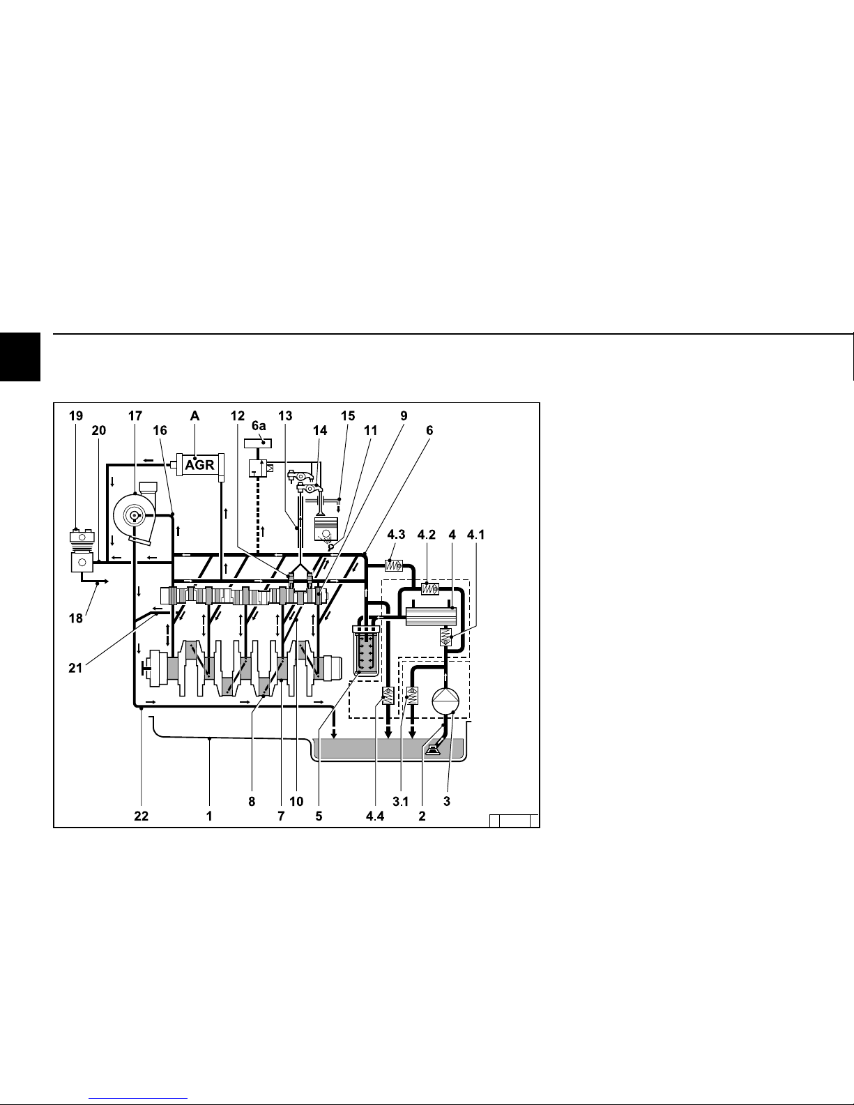
2.3 Lube oil circuit
2.3.1 Lube oil diagram
TCD 2013 L06 4V (example)
1 Oil tray
2 Intake pipe
3 Lube oil pump
3.1 Safety valve
4 Lube oil cooler
4.1 Reverse lock valve
4.2 By-pass valve
4.3 By-pass valve
4.4 Control valve
5 Exchangeable lube oil filter
6 Main oil pipe
6a Engine brake lubrication
A Exhaustgasrecirculation (EGR) lubrication
7 Crankshaft bearing
8 Con rod bearing
9 Camshaft bearing
10 Line to injection nozzle
11 Injection nozzle for piston cooling
12 Tappet with rocker arm pulse lubrication
13 Stop rod, oil supply for rocker arm
lubrication
14 Rocker arm
15 Return line to oil tray
16 Oil line to exhaust turbocharger
17 Exhaust turbocharger
18 Oil line to compressor or hydraulic pump
19 Compressor or hydraulic pump
20 Return line from compressor
21 Return line from cylinder head
22 Exhaust turbocharger return to crankcase
Page 21
2
Engine description
© 2005
© 38 991 0
© 38 992 2
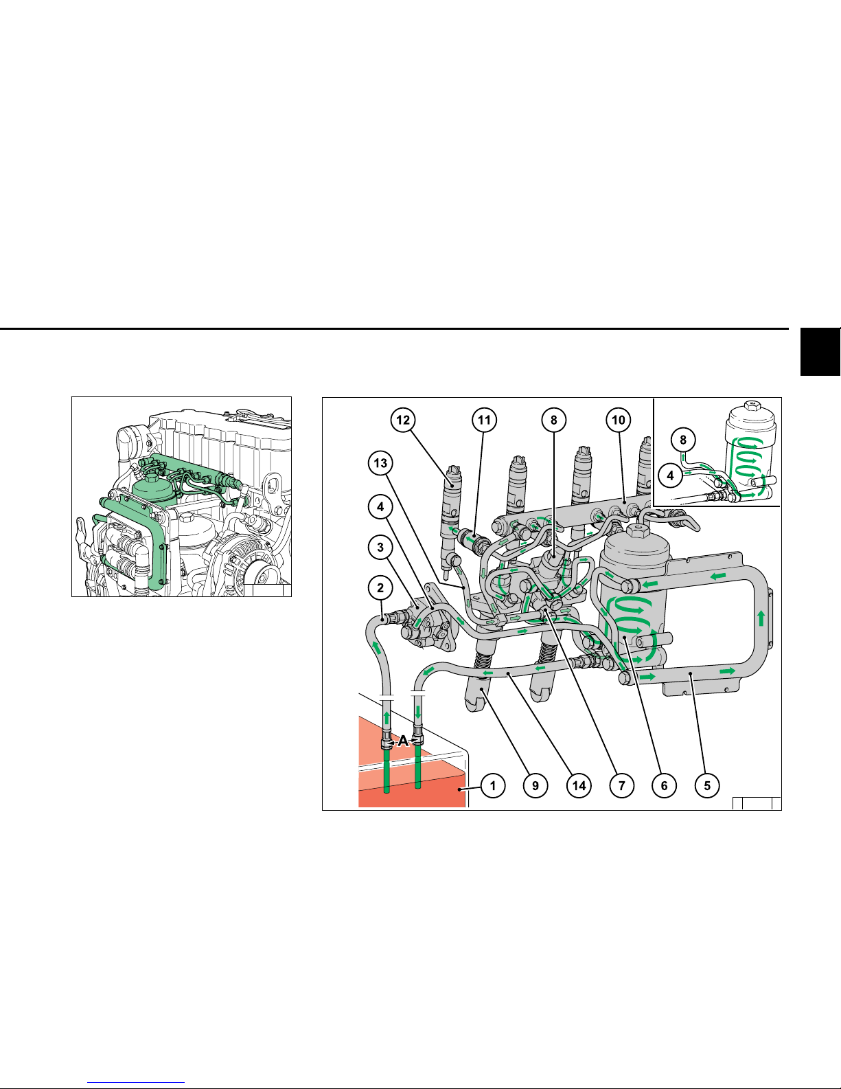
2.4 Fuel circuit
2.4.1 Fuel diagram
1 Fuel container
2 Line to fuel pump
3 Fuel pump
4 Line to fuel filter
5 Fuel cooling for engine control unit
(without cooler, upper right in diagram)
6 Fuel filter
7 Line to injection pumps
8 Fuel to control unit
9 Tappet rollers on camshaft
10 DCR Rail
11 Injection line to injection valve
12 Injectors
13 Fuel leak oil line
14 Return line to container
A Keep distance as large as possible
Page 22
2
Engine description
© 2005
© 39 982 3
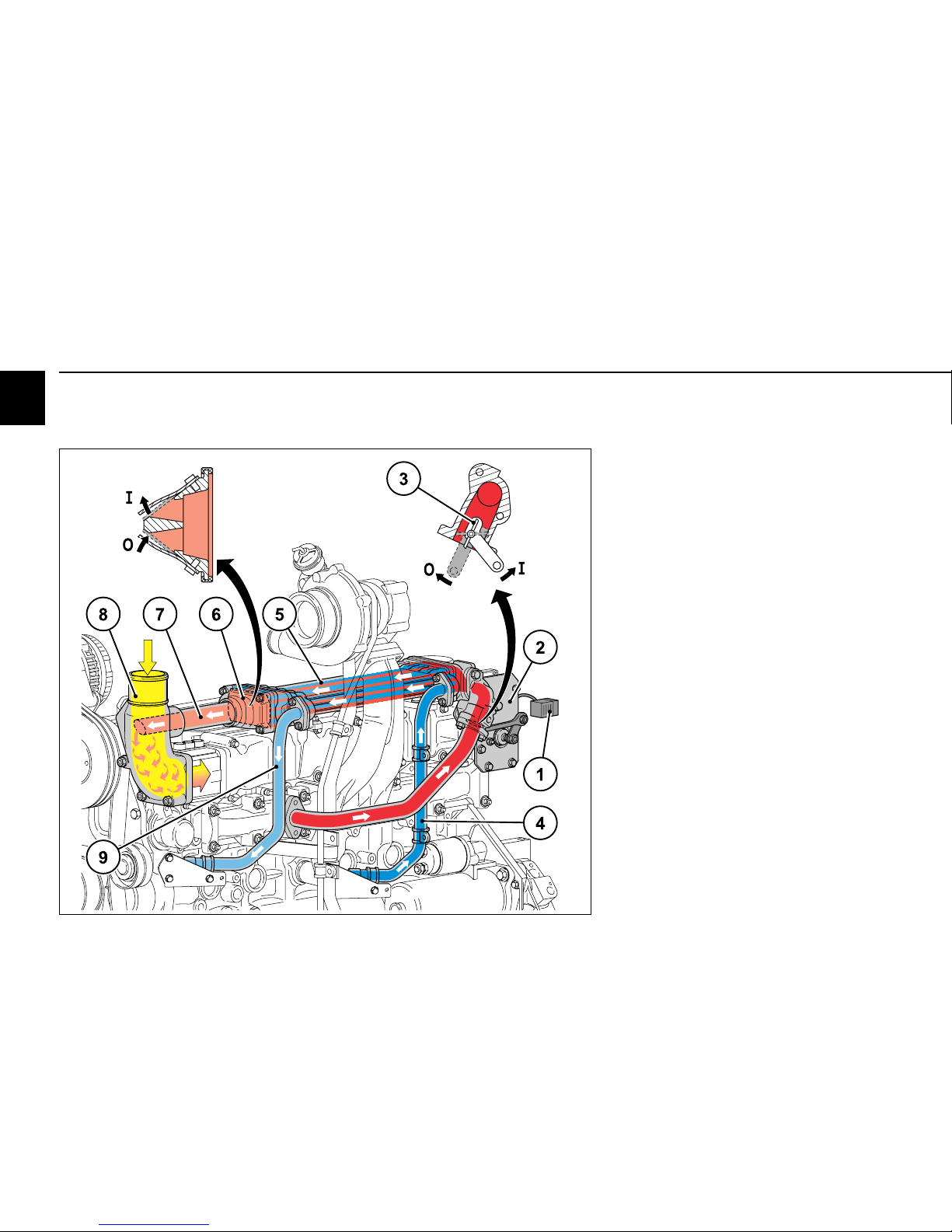
2.5 Coolant circuit
Page 23

2
Engine description
© 2005
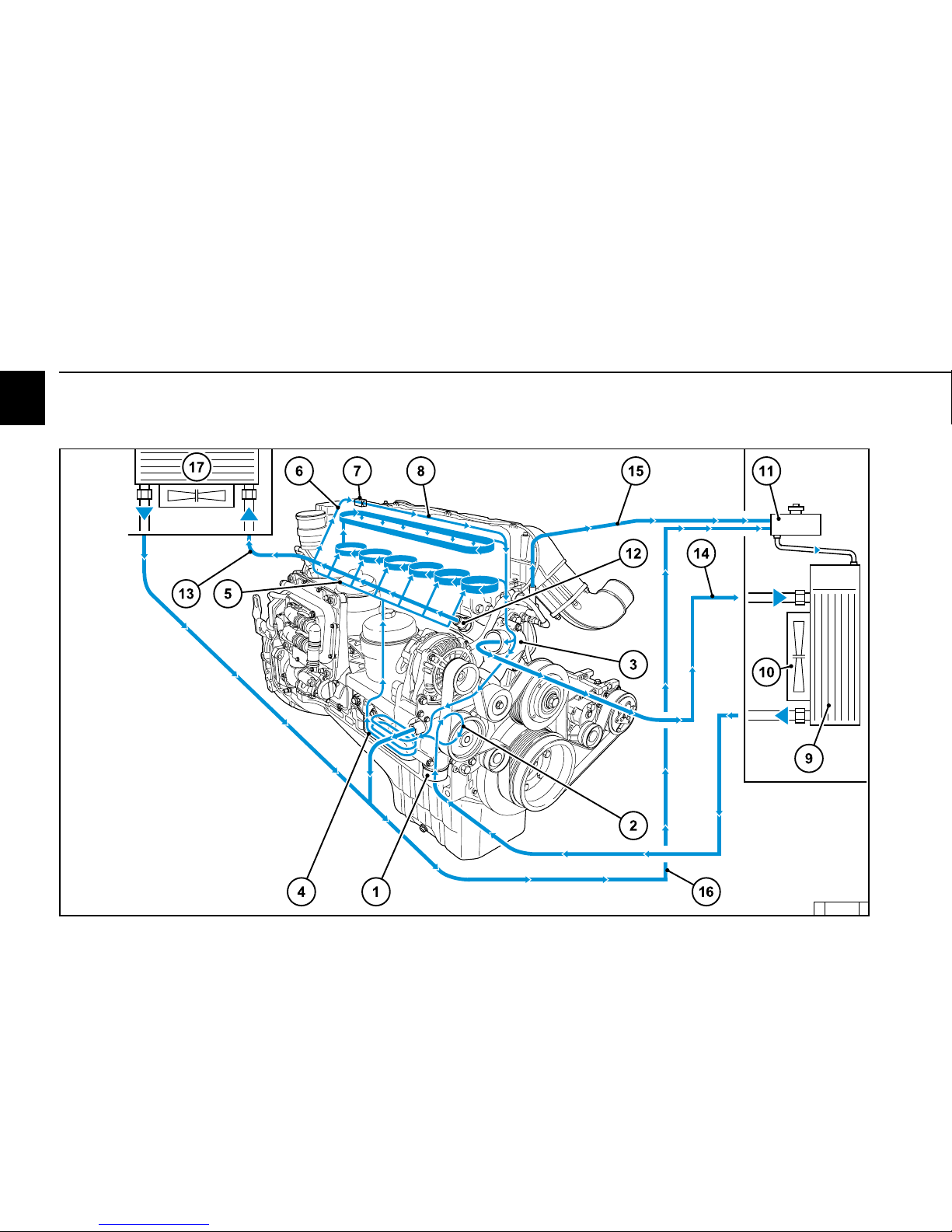
2.5 Coolant circuit
1 Coolant inlet to engine
2 Coolant pump
3 Thermostat housing
4 Lube oil cooler (plate cooling)
5 Cylinder head cooling and EGR cooling
6 Coolant supply to engine brake
7 Engine brake cooling
8 Return line to thermostat
9 Heat exchanger (customer)
10 Fan (customer)
11 Compensation tank (customer)
12 Heating connection
13 Compensation tank return line
to heater connection
14 Thermostat compensation tank return
15 Engine ventilation to compensation tank
16 Return line from engine heat exchanger
Page 24
2
Engine description
© 2005
2.5 Coolant circuit
1 Coolant inlet to engine
2 Coolant pump
3 Thermostat housing
4 Lube oil cooler (plate cooling)
5 Cylinder head cooling and EGR cooling
6 Coolant supply to engine brake
7 Engine brake cooling
8 Return line to thermostat
9 Heat exchanger (customer)
10 Fan (customer)
11 Compensation tank (customer)
12 Heating connection
13 Compensation tank return line
to heater connection
14 Thermostat compensation tank return
15 Engine ventilation to compensation tank
16 Return line from engine heat exchanger
2.6.1 Exhaust gas recirculation
diagram
Page 25
2
Engine description
© 2005
© 39 010 0
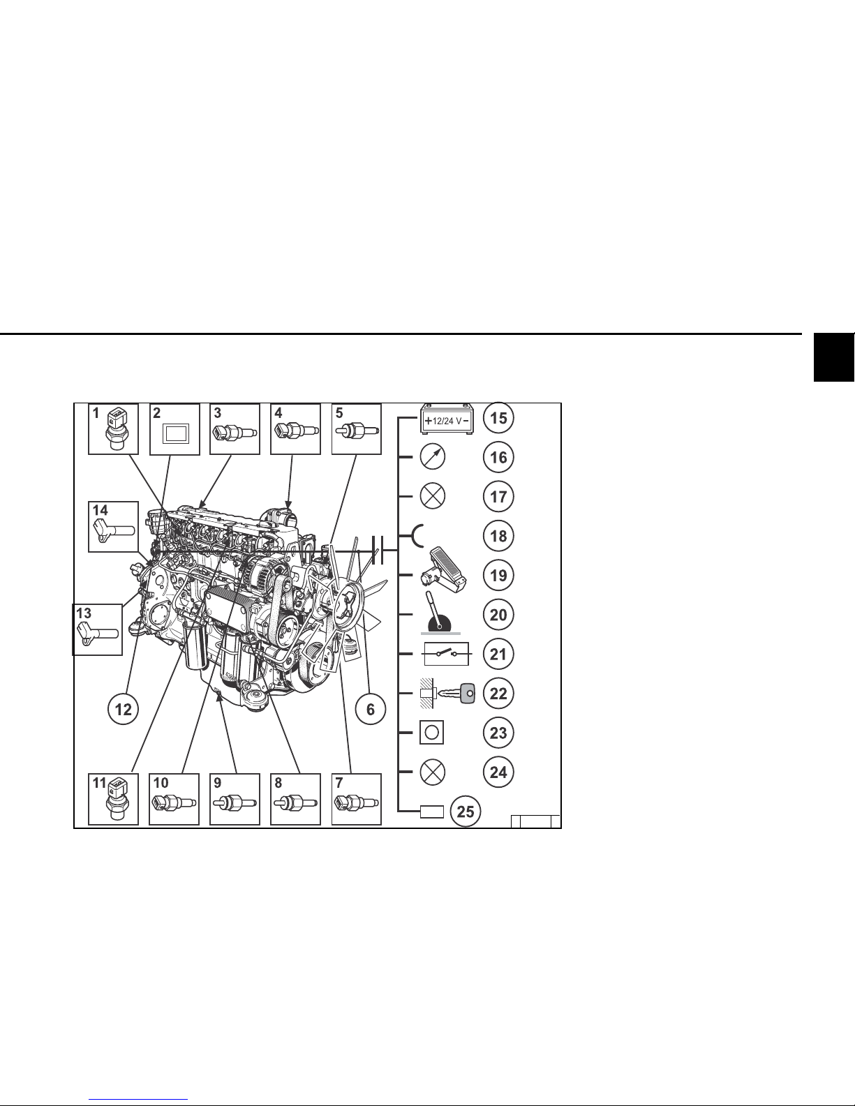
2.6 Electrics
2.6.1 Electrical cable connections
for monitoring (example)
1 Fuel pressure
2 Shutdown magnet (solenoid valve) example
3 Charge air pressure/temperature sensor
4 Coolant temperature
5 Cold start aid
6 Rail pressure (fuel pressure)
8 Oil temperature transmitter engine pre-heating
heating
7 Oil pressure transmitter
9 Oil level transmitter
10 Oil pressure sensor
11 Injectors engine brake (optional)
1 2 E.M.S II
13 Pick-up on SAE housing
14 Speed sensor
15 Energy supply
16 Multifunction displays
17 Outputs (configurable)
18 Inputs (configurable)
(PWM/digital/analogue)
19 Accelerator pedal
20 Hand throttle (optional)
21 Switch functions
22 Key switch
Start/stop
23 Diagnosis button
24 Fault light with blink code
25 Diagnosis interface/
CAN-Bus
Page 26

© 2005
Operation
3
3.1 Initial commissioning
3.2 Starting
3.3 Operation monitoring
3.4 Shutting down
3.5 Operating conditions
Page 27
3
© 2005
Operation
3.1 Initial commissioning
3.1.3 Filling / bleeding cooling
system
zz
zz
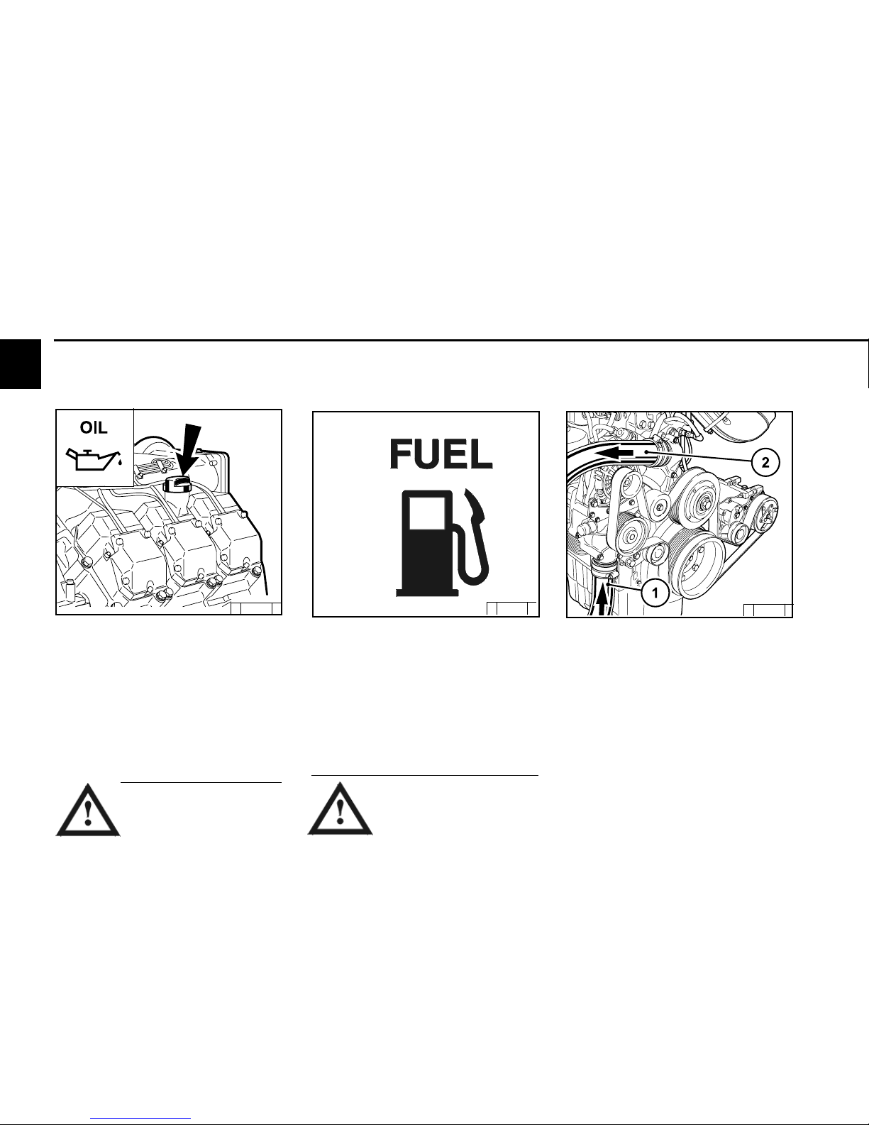
z Connect the coolant outlet 2 and coolant inlet
1 to the cooling system. Connect the lead line
from the compensation tank to the water pump
or to coolant inlet pipe 1.
z Connect vent lines from the engine and if
necessary from the cooler to the compensation
tank.
z Fill the cooling system through the
compensation tank
z Close the compensation tank with the valve.
z Start the engine and warm up until the
thermostat opens (line 2 heats up).
z Run engine run with open thermostat for
2 –3 minutes.
© 39 8 50 0
© 26 397 0
3.1.1 Filling engine oil
The engines are generally supplied without
oil filling.
Fill engine with lube oil through the oil filler (1)
on the cylinder head cover. Alternatively, you
can fill on the wheel box (2) or on the side of
the crankcase.
For oil filling amount see 9.1.
For quality and viscosity of oil see 4.1.
3.1.2 Filling fuel
Oil may not be filled into the
dust collecting tank of the
pre-separator, if this is
present.
Only use clean, standard, branded diesel fuel.
For fuel quality see 4.2.
Depending on the outdoor temperature, use
either summer or winter diesel fuel.
Only re-fuel when the engine is
not running!
Pay attention to cleanliness!
Do not spill any fuel!
© 26 398 0
Page 28
© 2005
Operation
3
3.1 Initial commissioning
3.1.4 Other preparations
z Check battery and cable connections, see
6.7.1.
z Trial run
- After preparations carry out a short
trial run of approx. 10 min. Do not fully load the
engine.
During and after the trial run
- Check engine for tightness.
With engine not running
- Check oil level, re-fill oil if necessary, see
6.1.2.
- Re-tighten V-belts, see 6.5.
z Running-in
It is recommended to check the oil level twice
a day during the running-in phase.
After the running-in phase, checking once a
day is sufficient.
z Check the coolant level in the compensation
tank and top up the coolant if necessary.
z Repeat the process with engine start if
necessary.
Never operate the engine without
coolant (not even briefly).
Page 29
3
© 2005
Operation
3.2 Starting
Start the engine for a maximum of 20 seconds
uninterrupted. If the engine does not start up,
wait for one minute and then repeat the starting
process. If the engine does not start up after
two starting processes, determine the cause
as per fault table (see 7.1).
If the engine does not start and the diagnostic lamp
flashes, the EMR3 system has activated the start
lock to protect the engine.
The start lock is released by switching off the
system with the ignition key for about 30 seconds.
3.2.1 Electrical starting
without cold start aid
Before starting make sure that
there is nobody in the engine/
work machine danger area.
After repairs: Check that all
protective equipment is
mounted and all tools have been removed
from the engine.
When starting with heating plugs/heating
flange, do not use additional start aids (e.g.
injection with start pilot)! Danger of accidents!
z Engine is electronically controlled by
Example: EMR3 (electronic engine control)
- engine is programmed and supplied with
the necessary function configurations.
z As far as possible separate engine from
driven devices by disconnecting.
z Engine connector plug must be connected
by the customer (e.g in driver’s cab/
device) to at least:
- Supply voltage
- Torque output
- Speed output.
z Warm up the engine for approx. 30 seconds
at a low idling speed.
z Do not run up the engine immediately to
high idling speed / full load operation from
cold.
If the starter is connected by a relay on the
EMR3,
- the maximum starting time is limited by
the EMR3.
- the pause between two start attempts
is given by the EMR3.
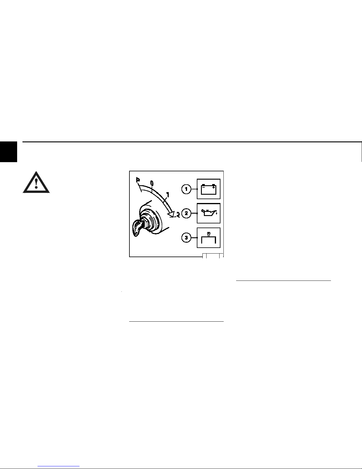
© 26 411 0
z Insert key
- Step 0 = no operating voltage.
z Turn key to the right
- Step 1 = operating voltage,
- Warning lights light up.
z Turn the key further to the right against the
spring load.
- Step 2 = start
z Release key as soon as the engine starts up.
- Warning lights go out.
- If the touch start function is programmed, a
short start command with the ignition key
suffices in position 2 or, if available, by a start
button.
The start is then continued automatically by the
EMR3.
- For special applications, the EMR3 can be
programmed by data record so that the control
unit performs other automatic start attempts if
the engine fails to start.
Start uninterruptedly for max. 20 s. If the engine
does not start, repeat the start procedure after
a 1 minute pause. If the engine has not started
after two attempts, find the cause in the fault
table (see 7.1).
Page 30

© 2005
Operation
3
3.3 Operation monitoring
with cold start aid
Heating plug/heating flange
© 26 411 0
z Insert key.
- Step 0 = no operating voltage.
z Turn key to the right.
- Step 1 = operating voltage,
- Warning lights 1+2+3 light up.
- Pre-heat until heating indicator goes out. If the
pre-heating indicator flashes, there is an
error, e.g. pre-heating relay sticking which
can fully discharge the battery at standstill.
- Engine is ready for operation.
z Turn the key further to the right against the
spring load to
- Step 2 = start
z Release key as soon as the engine starts up.
- Warning lights go out.
Caution: Engine must start within 30 seconds,
if not, repeat the starting process.
Page 31

3
© 2005
Operation
3.3 Operation monitoring
© 25 752 1
© 25 754 0
3.3.1 Engine oil pressure
Oil pressure light
z The oil pressure light comes on for about 2s
after switching on the system.
z The oil pressure light must be off when the
engine is running.
Oil pressure gauge
z Needle of oil pressure measuring instrument
must show the minimum oil pressure (see 9.1).
The EMR3 system monitors the engine condition
and itself.
The states are indicated by the diagnostic
lamp.
Lamp test:
z The diagnostic lamp lights for about 2s after
ignition (ignition lock stage 1).
Steady light:
z There is an error in the system or a variable of
the engine (temperature, pressure, etc.) is in
the warning area. Depending on the error, the
performance of the engine may be reduced by
the EMR3 to protect the engine so that it is not
in danger.
Fast flashing:
z Attention, the engine is in danger and
must be switched off.
z Depending on the application, the
control unit switches the engine off
automatically.
z The control unit may also specify an idle speed
to cool the engine before shutting down.
z There may be a start lock after stopping the
engine.
z Additional control lamps e.g. for oil pressure or
oil temperature may be on.
z The override key can bypass the reduction in
performance to avoid critical situations, as
well as delay the automatic shutdown or
bypass a start lock. This overwriting of the
engine protection functions is logged in the
control unit.
z The start lock is released by switching off the
system with the ignition key for about 30
seconds.
Page 32

© 2005
Operation
3
3.4 Shutting down
min
3.3.3 Coolant level
z Light on coolant level display comes on (contact
is via float switch/ level probe if coolant level
is at minimum):
Switch off the engine and determine the cause
as per fault table (see 7.1).
z Function check of coolant level:
Key in step 1 or 2
(Float switch or level probe)
Warning light comes on for approx. 2 seconds
- Coolant level OK:
Light goes out
- Coolant level not OK:
Light comes on again.
3.3.4 Lube oil level
z Light on lube oil level display comes on (contact
is via float switch / level proble if lube oil level
is at minimum):
Switch off the engine and determine the cause
as per fault table (see 7.1).
z Function check of lube oil level :
Key in step 1 or 2
(Float switch or level probe)
Warning light comes on for approx. 2 seconds
- Lube oil level OK :
Light extinguished.
- Lube oil level not OK :
Light comes on again.
© 26 278 1
© 26 291 1
© 26 246 0
3.3.2 Coolant temperature
z The needle of the temperature display should
always be in the green area, and only as an
exception in the yellow/green area. If the
needle rises into the orange area the engine is
getting too hot. Switch off the engine and
determine the cause as per fault table (see
7.1).
Page 33

3
© 2005
Operation
3.5 Operating conditions
P
1
2
0
+–
1
2
3
3.4.1 Electrical shutdown
© 26 411 0
z Turn the key to the left (to step 0) and
remove. Warning lights go out.
Note:
The control unit remains active for about another
40 seconds to save the system data (lag) and
then switches itself off.
Avoid shutting down from full
load operation if possible (coking/
blockage of the remaining oil in
the turbocharger bearing
housing).
Lube oil is no longer supplied to the
turbocharger!
Run the engine after relieving the load for about
one minute at low idling speed.
Page 34

© 2005
Operation
3
3.5 Operating conditions
z Cold start aids
- When there is a frost, start with heating
flange if if necessary (see 3.2.1).
The heating flange not only lowers the
starting limit temperature, but also
simplifies starting at temperatures which
don’t actually require a starting aid.
z Battery
- A well-charged battery is a
prerequisite for a good cold start,
see 6.7.1.
- Heating the battery to approx. 20 °C
(dismantle and store in a warm room) lowers
the starting limit temperatureby 4-5 °C.
3.5.1 Winter operation
z Lube oil viscosity
- Select the viscosity (SAE class)
according to the ambient temperature
before starting the engine, see 4.1.2.
- Observe shorter oil change times when
operating below -10 °C, see 6.1.1.
z Diesel fuel
- Below 0 °C use winter fuel,see 4.2.2.
z Coolant
- Mixing ratio anti-freeze / water for lowest
temperature (max. - 35 °C), see 4.3.1.
z Additional maintenance work
- Check the fuel container weekly for
contamination, clean if necessary.
- If necessary, adjust the oil filling of the oil
bath air filter (as engine oil) according to
the outside temperature.
© 26 248 0
Page 35

3
© 2005
Operation
3.5.2 High ambient temperature,
high altitude
z When the altitude or ambient temperature
increases, the air density decreases.
This impairs the maximum engine performance,
exhaust quality, temperature level and, in extreme cases, the starting performance.
For transient operation, usage up to
1000 m altitude and a temperature of 30°C is
permissible.
z In case of doubt regarding engine usage, ask
your engine or device supplier whether
necessary fuel stop reduction has been carried
out in the interest of operational safety, service
life and exhaust quality (smoke), or contact
your service representative.
© 25 901 1
Page 36

4
© 2005
Operating substances
4.1 Lube oil
4.2 Fuel
4.3 Coolant
Page 37

4
© 2005
only with engine pre-heating
30 298 1
Operating substances 4.1 Lube oil
4.1.1 Quality
Lube oils are classified by DEUTZ into quality
classes according to their performance
capability. Oils according to other comparable
specifications can be used.
Permissible oils:
Deutz DQC I-02 DQC II-05 DQC III *+DQC IV
#
ACEA E2-96 E3-96/E5-02/ E4- 99/
E7-04 E6-04
API CF/CF-4 CH-4/CG-4 DHD - DHD-1 -
DQC III-05 * Annex 1
DQC IV-05
#
only fully synthetic
The exact assignment of permissible oil quality
and oil change intervals to the engines is
listed in chapter 6.1.1.
In case of doubt, please ask your service
representative.
*For oil change intervals see 6.1.1
For oil filling amounts see 9.1
4.1.2 Viscosity
Since lube oil changes its viscosity (viscidity)
depending on temperature, the ambient
temperature of the location of engine operation
is decisive for the selection of viscosity class
(SAE class). Refer to the oil viscosity diagram
on the right to achieve optimal operating
performance.
Falling below the temperature limits
occasionally can impair the cold start ability,
but will not lead to engine damages. In order
to minimise wear, the operating limits should
not be exceeded over a long period of time.
Oil changes determined by the time of year
can be avoided by using multi-viscosity oils.
Multi-viscosity oils, in particular smooth running
oils, also have the effect of reducing fuel
consumption.
Page 38

4
© 2005
4.1 Lube oil Operating substances
DEUTZ lube oil quality level DQC III Annex 1
Manufacturer Lube oil type SAE class Availability
DEUTZ DEUTZ ÖlTLX-10W40 FE 10W-40 Europe
ADDINOL ADDINOL SuperTruck MD 1048 10W-40 Europe, Asia
ADDINOL Ultra TruckMD 0538 5W-30 Europe, Asia
AGIP Agip SigmaUltra TFE 10W-40 worldwide
Autol Valve UltraFE 10W-40 Germany
ARAL Aral MegaTurboral 10W-40 worldwide
Aral SuperTurboral 5W-30 worldwide
AVIA TURBOSYNTHHT-E 10W-40 Germany
BAYWA BayWa SuperTruck 1040 MC 10W-40 Southern Germany
BayW a Turbo4000 10W-40 Southern Germany
BP OIL International BP Vanellus E7 Plus 10W-40 Europe
BP Vanellus E7Supreme 5W-40 Europe
Castrol CastrolSYNTRUCK 5W-40 Europe, North America, Brazil, Argentina, Australia, South Africa
Castrol Castrol DYNAMAX 7.5W-40 Europe, North America, Brazil, Argentina, Australia, South Africa
CEPSA EUROTRANSSHPD 10W-40 Spain, Portugal
CHEVRON Chevron Delo400 Synthtic 5W-40 North America
DEA DEA CronosSynth 5W-30 Germany, Europe
DEA Cronos PremiumLD 10W-40 Germany, Europe
DEA Cronos PremiumLD 10W-40 Europe
ESSO EssolubeXTS 501 10W-40 Europe
FUCHS EUROPE Fuchs Titan Cargo MC 10W-40 worldwide
Fuchs Titan UnicPlus MC 10W-40 worldwide
MOBIL OIL Mobil Delvac 1 SHC 5W-40 Europe, SE Asia, Africa
Mobil De lva c 15W-40 worldwide
Mobil Delvac XHP Extra 10W-40 Europe, SE Asia
Lube oil refinery Wintershall TFG 10W-40 Europe, Salzbergen
Shell International ShellMyrina TX / 5W-30 Europe, code
Shell Rimula Ultra country specific, varies
Shell MyrinaTX / 10W-40 Europe, code
Shell Rimula Ultra country specific, varies
Texaco Ursa Super TDX 10W-40 10W-40 Europe
Ursa Premium FE 5W-30 5W-30 Europe
TOTALFINA ELF TOTAL RUBIA TIR 8600 10W-40 worldwide
ELF PERFORMANCE 10W-40 worldwide
EXPERTY MX 1010
ELF PERFORMANCE 10W-40 Germany, Benelux,
EXPERTY MX 1012 Scandinavia, Austria
FINA KAPPA FIRST 5W-30 Europe
FINA KAPPA ULTRA 10W-40 Europe
This table will be extended if necessary.
Page 39

4
© 2005
Operating substances 4.2 Fuel
4.2.1 Quality
Use standard diesel fuels with a sulphur content
of less than 0.5 %. If the sulphur content is higher,
the oil change intervals must be reduced (see
6.1.1).
The following fuel specifications are
permitted:
zz
zz
z Diesel fuels
- DIN EN 590
zz
zz
z JIS K 2204 grade 1 and 2 *
zz
zz
z ASTM D 975-88; 1-D and 2-D *
* as long as the lubrication properties
correspond to diesel fuel EN 590 (positive
test results are necessary)
(see TR 0199-99-3005)
If other fuels are used which do not meet the
requirements of the technical circular, the
warranty will be voided.
Technical circular is obtainable from the DEUTZ
Service Organisation.
The certification measurements for the
observance of legal emission limits are carried
out with the test fuels defined by legislation.
These correspond to the diesel fuels
described in section 1 in accordance with EN
590 and ASTM D 975. Emission values cannot
be guaranteed with the other fuels described
in this circular.
4.2.2 Winter fuel
At low ambient temperatures paraffin
discharges can lead to blockages in the fuel
system and cause operating faults. Use winter
fuel at outside temperatures below 0 °C (to
-20 °C) (generally offered by petrol stations
in good time before the cold season begins).
z Paraffin should be added at temperatures
below -20 °C. The mixing ratios required
are as per the diagram on the right.
z Special diesel fuels can be used for arctic
climates to -44 °C.
Íf it is necessary to use summer diesel fuel
under 0 °C, paraffin can also be added by up
to 30% as per the diagram on the right.
Only carry out mixing in the tank!
First pour in the necessary
amount of paraffin, then the
diesel fuel.
Diagram key:
I Summer diesel fuel
I I Winter diesel fuel
A Outside temperature
B Paraffin mixing proportion
© 43 923 0
For the engines TCD 2013 4V
and fuel according to ASTM D
975 1-D/2-D, adding paraffin
is not permissible.
Generally, sufficient resistance to cold can
also be achieved by adding a flow ameliorant.
For questions regarding this please contact
your DEUTZ partner.
Page 40

4
© 2005
.
4.3 Coolant Operating substances
Contact your local waterworks for information
regarding the water quality.
4.3.2 Coolant preparation
Particular attention should be paid to preparing
and inspecting the coolant in liquid-cooled
engines, as otherwise corrosion, cavitation
and freezing damages can occur on the
engine.
Preparation of the coolant involves mixing a
cooling system preservative to the cooling
water.
The cooling system must be monitored
regularly, see 5.1. This includes checking the
concentration of the cooling system
preservative, as well as inspecting the coolant
level.
The inspection of the concentration of cooling
system preservative can be carried out with
standard testing devices. (Example: gefo
glycomat R ).
Mixing cooling system
preservatives of a nitrite
base with substances of an
amine basis forms harmful
nitrosamines.
4.3.3 Cooling system preservative
Using the cooling system preservative, order
no. 01011490/ 01016416/12211500 (nitrite,
amine and phosphate free, available in 5/ 20/
210 litre containers), provides effective
protection against corrosion, cavitation and
freezing.
The cooling system preservative in the coolant
must not fall below or exceed the following
concentrations:
Cooling system Water Cold protection
preservative proportion to
proportion
min. 35 % 65% -22 °C
40 % 60% -28 °C
max. 45 % 55% -35 °C
For filling amounts see the table overleaf in
combination with the information in chapter
9.1.
The use of other cooling system
preservatives, e.g. chemical corrosion
preservatives, is possible in exceptional
cases, consult DEUTZ Service.
Order the cooling system preservative from:
DEUTZ AG
4.3.1 Water quality for coolant
The following values may not be exceeded or
fallen short of.
A test case can be requested from DEUTZ
Service under the order no. 1213 0382 for
checking your water quality.
Analysis values min. max.
ph value at 20 °C 6.5 8.5
Chloride ion content[mg/dm3] - 100
Sulphate ion content[mg/dm3] - 100
Total hardness [°dGH] 3 20
* Carbonate hardness proportion of total
hardness min 3 dGH
Cooling system preservatives
must be disposed of in an
environmentally friendly manner.
Page 41

© 2005
5
Maintenance
5.1 Maintenance schedule
5.2 Maintenance diagram
5.3 Maintenance work carried out
Page 42

© 2005
5
Activity
Maintenance 5.1 Maintenance schedule
check= z set= clean=L renew=
Industrial engines
The engine maintenance times given are maximum permissible job
times. Depending on the usage circumstances, shorter maintenance
times may be necessary. Observe the instruction manual of the
equipment manufacturer.
# Maintenance only to be carried out by authorised service personnel
Section
⇓ check 2x daily before or during the 1st trial run, during the running-in phase or
when commissioning new and overhauled engines.
⇓ every 10 oh or daily
in operating hours (oh) every year(s)
E10 E20 E30 E40 E45 E50 E60 E70
500 1,000 1,500 3,000 6,000 12,000 1 2
EGR* exhaust gas recirculation (system); If the warning system (light/siren) is activated, the fuel pre-filter must be emptied immediately.
1)
The intervals can be reduced, depending on the degree of soiling of the fuel used.
zz
z
z
1)
zz
zzz
zz
zz L
L
z
L
z
z
zz
zz
z
zz
zz
zz
Lube oil level, if necessary re-fill 6.1.2
Lube oil (oil change intervals depending on engine application and oil quality), see TR 0199-99-3002
6.1.1/ 6.1.2
Oil filter cartridge 6.1.3
Fuel filter cartridge 6.2.1
Electronic injector check via EMR3
#
Fuel filter insert1) (fuel pre-filter) 4.2
Coolant (additive concentration) 4.3.1/2/3
Coolant level –
Intake air filter
(if available, maintenance as per maintenance display)
6.4.3 /6.4.4
Charge air cooler (drain lube oil/condensation)
EGR(option)* Check non-return valve (option)
EGR (option) Check cap and adjustment mechanism for clearance, renew if necessary.
Cooler EGR(option)
Check function of heating flange
Battery and cable connections 6.7.1
Engine monitoring, warning system 3.3
#
Valve clearance 6.6.1
V-belt/tension pulley (renew when wear limit reached) 6.5.1/6.5.3
Crankcase pressure bleed valve (option)
#
Engine tightness (visual inspection for leaks). –
Engine mounting (renew in case of damage) 9.2
Fastenings, hose connections / clamps –
General overhaul
#
Page 43

© 2005
5
Activity
5.1 Maintenance schedule Maintenance
check= z set= clean= L renew=
max. permissible job times in operating hours (oh) every
⇓
check 2x daily before or during the 1st trial run, during the running-in phase or
when commissioning new and overhauled engines.
⇓ every 10 oh or daily
in operating hours (oh) every
E10 E30 E40 E70
500 6.000 12.000 1 2
Enhancements or modifications for engines with
EPA acceptance
The engine maintenance times given are maximum
permissible job times. Depending on the usage
circumstances, shorter maintenance times may be
necessary. Observe the instruction manual of the
equipment manufacturer. # Maintenance only to be
carried out by authorised service personnel
Section
Charge air cooler (drain lube oil/condensation)
#
Charge air cooler inlet surface (clean if necessary) #
Crankcase pressure bleed valve (option)
#
z L
z L
L
Page 44

Maintenance 5.1 Maintenance schedule
Lube oil level, if necessary re-fill 6.1.2
Lube oil (oil change intervals depending on engine application and oil quality), see TR 0199-99-3002
6.1.1/ 6.1.2
Oil filter cartridge 6.1.3
Fuel filter cartridge 6.2.1
Electronic injector check via EMR3
#
Fuel filter insert1) (fuel pre-filter) 4.2
Coolant (additive concentration) 4.3.1/2/3
Coolant level –
Intake air filter
(if available, maintenance as per maintenance display)
6.4.3 /6.4.4
Charge air cooler (drain lube oil/condensation)
EGR(option)* Check non-return valve (option)
EGR (option) Check cap and adjustment mechanism for clearance, renew if necessary.
Cooler EGR(option)
Check function of heating flange
Battery and cable connections 6.7.1
Engine monitoring, warning system & 3.3
#
Valve clearance 6.6.1
V-belt/tension pulley (renew when wear limit reached) 6.5.1/6.5.3
Crankcase pressure bleed valve (option)
#
Engine tightness (visual inspection for leaks). –
Engine mounting (renew in case of damage) 9.2
Fastenings, hose connections / clamps –
General overhaul
#
Service Yearly op. Average
group performance
Drive
speed
km
approx.km/h
I <30 000 20
II >30 to 100 000 40
III >100 000 60
Vehicle engines
Service group I <30 000km 20
approx.km/h
The engine maintenance times given are maximum permissible
job times. Depending on the usage circumstances, shorter
maintenance times may be necessary. Observe the instruction
manual of the equipment manufacturer.
#
Maintenance only
to be carried out by authorised service personnel
Section
EGR* Exhaust gas recirculation (system); If the warning system (light/siren) is activated, the fuel pre-filter must be emptied immediately.
1)
The intervals can be reduced, depending on the degree of soiling of the fuel used.
⇓ check 2x daily before or during the 1st trial run, during the running in phase or when commissioning new and overhauled engines.
⇓ every 200 km or daily
OPERATIONAL PERFORMANCE IN (km) ye a r(s)
E10 E20 E30 E40 E45 E50 E60 E70
Activity
check= z set= clean= L renew=
5,000
10.000
20.000
30.000
120..000
240.0 0 0
1
2
zz
z
z
1)
zz
zz z
zz
zz L
L
z
L
z
z
zz
zz
z
zz
zz
zz
5
Page 45

5.1 Maintenance schedule Maintenance
Lube oil level, if necessary re-fill 6.1.2
L
ube oil (oil change intervals depending on engine application and oil quality), see TR 0199-99-3002
6.1.1/ 6.1.2
Oil filter cartridge 6.1.3
Fuel filter cartridge 6.2.1
Electronic injector check via EMR3
#
Fuel filter insert1) (fuel pre-filter) 4.2
Coolant (additive concentration) 4.3.1/2/3
Coolant level –
Intake air filter
(if available, maintenance as per maintenance display)
6.4.3 /6.4.4
Charge air cooler (drain lube oil/condensation)
EGR(option)* Check non-return valve (option)
EGR (option) Check cap and adjustment mechanism for clearance, renew if necessary.
Cooler EGR(option)
Check function of heating flange
Battery and cable connections 6.7.1
Engine monitoring, warning system & 3.3
#
Valve clearance 6.6.1
V-belt/tension pulley (renew when wear limit reached) 6.5.1/6.5.3
Crankcase pressure bleed valve (option)
#
Engine tightness (visual inspection for leaks). –
Engine mounting (renew in case of damage) 9.2
Fastenings, hose connections / clamps –
General overhaul
#
check= zset= clean= L renew=
Vehicle engines
Service group Il 100 000km 40approx.km/h
The engine maintenance times given are maximum permissible
job times. Depending on the usage circumstances, shorter
maintenance times may be necessary. Observe the instruction
manual of the equipment manufacturer. # Maintenance only to be
carried out by authorised service personnel
Section
Activity
EGR* Exhaust gas recirculation (system); If the warning system (light/siren) is activated, the fuel pre-filter must be emptied immediately.
1)
The intervals can be reduced, depending on the degree of soiling of the fuel used.
20,000
40,000
50,000
240,000
480,000
1
2
⇓ check 2x daily before or during the 1st trial run, during the runningin phase or when commissioning new and overhauled engines.
⇓ every 200 km or daily
OPERATIONAL PERFORMANCE IN (km) ye a r(s)
E10 E20 E30 E40 E40 E50 E60 E70
Service Yearly op. Average
gro up performance
Drive
speed
km
approx.km/h
I <30 000 20
II >30 to 100 000 40
III >100 000 60
zz
z
z
1)
zz
zz z
zz
zz L
L
z
L
z
z
zz
zz
z
zz
zz
zz
5
Page 46

© 2005
5
Maintenance
5.1 Maintenance schedule
check= zset= clean= L renew=
ServiceYearly op. Average
gro up performance
Drive
speed
km
approx.km/h
I <30 000 20
II >30 to 100 000 40
III >100 000 60
Vehicle engines
Service group Ill >100 000 km 60approx.km/h
The engine maintenance times given are maximum
permissible job times. Depending on the usage circumstances,
shorter maintenance times may be necessary. Observe the
instruction manual of the equipment manufacturer.
# Maintenance only to be carried out by authorised service personnel
Section
30.000
60.000
90.000
120.000
360.000
1000.000
1
2
EGR* Exhaust gas recirculation (system); If the warning system (light/siren) is activated, the fuel pre-filter must be emptied immediately.
1)
The intervals can be reduced, depending on the degree of soiling of the fuel used.
Activity
⇓
check 2x daily before or during the 1st trial run, during the running-in phase
or when commissioning new and overhauled engines
⇓ every 200 km or daily
OPERATIONAL PERFORMANCE IN (km) every
Service group III year(s)
E10 E20 E30 E40 E45 E50 E60 E70
zz
z
z
1)
zz
zz z
zz
zz L
L
z
L
z
z
zz
zz
z
zz
zz
zz
Lube oil level, if necessary re-fill 6.1.2
L
ube oil (oil change intervals depending on engine application and oil quality), see TR 0199-99-3002
6.1.1/ 6.1.2
Oil filter cartridge 6.1.3
Fuel filter cartridge 6.2.1
Electronic injector check via EMR3
#
Fuel filter insert1) (fuel pre-filter) 4.2
Coolant (additive concentration) 4.3.1/2/3
Coolant level –
Intake air filter
(if available, maintenance as per maintenance display)
6.4.3/6.4.4
Charge air cooler (drain lube oil/condensation)
EGR(option)* Check non-return valve (option)
EGR (option) Check cap and adjustment mechanism for clearance, renew if necessary.
Cooler EGR(option)
Check function of heating flange
Battery and cable connections 6.7.1
Engine monitoring, warning system & 3.3
#
Valve clearance 6.6.1
V-belt/tension pulley (renew when wear limit reached) 6.5.1
Crankcase pressure bleed valve (option)
#
Engine tightness (visual inspection for leaks). –
Engine mounting (renew in case of damage) 9.2
Fastenings, hose connections / clamps –
General overhaul
#
Page 47

5
© 2005
Maintenance 5.1 Maintenance schedule
5.1.1 Standard maintenance schedule
Intervals Deutz maintenance and Activity Execution by:
at/after service schedules
50 oh E 10 after commissioning and E 50-E 70 autho rised specialists
daily E 20 daily inspection round the user / authorised specialists
500 o h E 30 inspection authorised specialists
1000 oh E 40 intermediate overhaul authorised specialists
1500 oh E 45 extended intermediate overhaul authorised specialists
3 000 oh E 60 partial overhaul authorised specialists
6000 oh E 60 partial overhaul authorised specialists
10 000 oh (2012) E 70 overhaul authorised specialists
13 000 oh (2013) E 70 overhaul authorised specialists
*) approximate value, depends on the type of engine application and/or regular engine maintenance.
Please contact your responsible DEUTZ Service partner.
Page 48

5
© 2005
All maintenance work should
only be carried out when the
engine is not running.
The maintenance diagram shown on this
page is supplied with every engine in selfadhesive form. It should be stuck onto a well
visible location on the engine or equipment.
Check that this is the case!
If not, request a replacement from your engine
or equipment supplier!
The maintenance schedule is decisive for
standard maintenance, see 5.1.
5.2 Maintenance diagram Maintenance
Page 49

Date
Op. hrs.
Signature / stamp Op. hrs. Date
Signature / stamp
5
© 2005
-
250
500
750
1000
1250
1500
1750
2000
2250
2500
2750
50-150
*
125
375
625
875
1125
1375
1625
1875
2115
2375
* after commissioning new and overhauled engines
The maintenance work carried out methodically can be recorded in the table and confirmed.
5.3 Maintenance work carried out Maintenance
Page 50

Op. hrs.
Date
Date Signature / stamp
Op. hrs. Signature / stamp
5
© 2005
Maintenance 5.3 Maintenance work carried out
2875
3125
3375
3625
3875
4125
4375
4625
4875
5125
5375
5625
The maintenance work carried out methodically can be recorded in the table and confirmed.
3000
3250
3500
3750
4000
4250
4500
4750
5000
5250
5500
5750
Page 51

Date
Op. hrs.
Signature / stamp Op. hrs. Date
Signature / stamp
5
© 2005
The maintenance work carried out methodically can be recorded in the table and confirmed.
5875
6125
6375
6625
6875
7125
7375
7625
7825
8125
8375
8625
6000
6250
6500
6750
7000
7250
7500
7750
8000
8250
8500
8750
5.3 Maintenance work carried out Maintenance
Page 52

Op. hrs.
Date
Date Signature / stamp
Op. hrs. Signature / stamp
5
© 2005
Maintenance 5.3 Maintenance work carried out
8875
9125
9375
9625
9875
10125
10375
10625
10875
10125
10375
10625
9000
9250
9500
9750
10000
10250
10500
10750
10000
10250
10500
10750
The maintenance work carried out methodically can be recorded in the table and confirmed.
Page 53

6
© 2005
Care and maintenance work
6.1 Lubrication system
6.2Fuel system
6.3Cooling system
6.4Combustion air filter
6.5 Belt drive
6.6Setting work
6.7Add-on parts
Page 54

6
© 2005
Care and maintenance work 6.1Lubrication system
6.1.1 Oil change intervals
z The oil change times depend on the engine
application and the quality of the lube oil.
z If the oil change times are not reached
within a year, the oil change should be
carried out at least 1x yearly.
z The following conditions apply for the table
– Sulphur content max. 0.5 % of weight for
diesel fuel.
– Constant ambient temperature ³ -10 °C
(+14 °F)
z For fuels
– with sulphur content > 0.5 to 1%
or
– Constant ambient temperatures < -10 °C
(+14 °F)
or
– with bio-diesel fuels according to DIN
51606- FAME the oil change times
should be halved.
z For fuels with a sulphur content higher
than 1% ask your responsible
service representative.
Carry out oil changes on warm engine when the
engine is not running (lube oil temperature < 80 °C).
z If the lube oil change intervals are planned
in terms of operating hours, the lube oil
change intervals for installed engines
6.1.1.1 apply.
Page 55

6
© 2005
6.1 Lubrication system Care and maintenance work
6.1.1.1 Lube oil change intervals for installed engines
Lube oil quality
Deutz lube oil quality class DQC I-02 DQC II-05 DQC III-05 DQC iV-05
ACEA specificat ion E2-96 E3-96/E5-02/E07-04 E4-99/E6-04 E4-99/E6-04
see 6.1.1.3 only fully synthetic
API specification CF/CF-4 CG-4/CH-4/ CI-4 - worldwide specification - DHD-1 - special DEUTZ release list - - see chap. 4.1.2.1 Standard lubricant code designation EO... EO...C - for building machines and building vehicles EO...A, EO...B
Engine Engine version Lube oil change intervals in oh
series
TCD All engines with:
2012 Crankcase ventilation:
L04/06 4V open - 500 500 500
closed - - 500 500
2013 Crankcase ventilation:
L04/06 4V open - 500 500 500
closed - - 500 500
Page 56

6
© 2005
average driving speed km/h
Care and maintenance work 6.1 Lubrication system
6.1.1.2 Lube oil change intervals for vehicle engines
Lube oil quality
Deutz lube oil quality class DQC I-02 DQC II-05 DQC III-05 DQC iV-05
ACEA specificat ion E2-96 E3-96/E5-02/E07-04 E4-99/E6-04 E4-99/E6-04
see 6.1.1.3 only fully
synthetic
API specification CF/CF-4 CG-4/CH-4/ CI-4 - worldwide specification - DHD-1 - special DEUTZ release list - - see chap. 4.1.2.1 -
Application
Engine version Crankcase
TCD 2012/2013 L04/ 06 4V ventilation Lube oil change intervals in km
Building site
TCD
2012 4V open - 20 000 20 000 20 000
closed - - 20 000 20 000
vehicles /
TCD 2013 L06 4V
city buses/ Coach bus closed - 30 000 50 000 50 000
25 Inter city bus closed - 20 000 30 000 30 000
City busbus closed - 15 000 20 000 20 000
City TCD 2013 L04 4V closed - 25 000 45 000 45 000
transport TCD 2013 L06 4V closed - 30 000 50 000 50 000
TCD
2012 4V open - 30 000 30 000 30 000
closed - - 30 000 30 000
Local transport 4 0 TCD 2013 L04 4V closed - 40 000 60 000 60 000
TCD 2013 L06 4V closed - 50 000 75 000 75 000
TCD
2012 4V open - 40 000 40 000 40 000
Long distance
60 closed - - 40 000 40 000
transport
TCD 2013 L04 4V closed - 60 000 80 000 80 000
TCD 2013 L06 4V closed - 75 000 100 000 100 000
Page 57

6
© 2005
© 25 729 0
© 26 02 2 0
© 26 02 3 0
6.1 Lubrication system Care and maintenance work
6.1.2 Checking oil level / changing
engine oil
6.1.2.1Checking oil level
z Position the engine or vehicle so as to be level.
z – Engine warm:
Switch off the engine, wait for 5 minutes and
check oil level.
z – Engine cold:
Check oil level.
z Extract oil dipstick.
z Wipe with a fibre-free, clean cloth.
z Insert until it stops and extract again.
z Check oil level and re-fill to „MAX“ if necessary.
– If the oil level lies just above the „MIN“-
line marking, re-filling is necessary.
6.1.2.2 Changing engine oil
z Warm up engine.
z Position the engine or vehicle so as to be level.
– Lube oil temperature approx. 80 °C.
z Switch off engine.
z Position oil drip cup under the engine.
z Unscrew oil drain screw.
z Drain off oil.
z Screw in oil drain screw with new sealing ring
and tighten. (For tightening torque
see 9.2).
z Pour in lube oil.
– For quality / viscosity data see 4.1.
– For filling quantities, see 9.1.
z Check oil level, see 6.1.2.1.
Caution when draining
hot oil: danger of scalding!
Collect the used oil, do not allow to
seep into floor!
Dispose of according to instructions!
The oil level may not fall short of the „MIN“ line
marking.
Page 58

6
© 2005
© 25 882 0
© 25 881 0
© 25 880 0
Care and maintenance work 6.1 Lubrication system
6.1.3 Changing oil filter insert
z When anti-rotation lock is installed:
Loosen clamping screws and remove tightening clamps from below.
z Loosen lube oil filter cartridge with stan-
dard tool and unscrew.
z Collect any oil which may run out.
z Clean the sealing surface of the filter sup-
port for any possible dirt.
z Lightly oil the rubber seal of the new lube
oil cartridge.
z Screw on the cartridge by hand until the
seal makes contact.
Careful with hot oil:
danger of scalding!
z Tighten lube oil filter cartridge three quarters
of a turn (approx. 10 Nm).
z If there is an anti-rotation lock:
Position the tightening clamps and tighten
with clamping screws.
z Check oil level, see 6.1.2.
z Check oil pressure, see 3.3.1.
z Check the seal of the lube oil filter cartridge
for tightness.
Page 59

6
© 2005
6.1 Lubrication system Care and maintenance work
6.1.4 Cleaning / changing oil filter
(cup)
© 30 0 74 1
z Switch off engine.
z Loosen lube oil filter cover 1 with two or three
turns and wait for 30 seconds.
z Unscrew lube oil filter cover 1 with paper filter
cartridge 5 in anti-clockwise direction.
z Carefully loosen paper filter cartridge 5 from
the guide 4, which is inserted in the housing 3,
from above.
z Collect any lube oil which may run out.
z Crease the paper filter cartridge 5 in the
collection vessel slightly at the side until the
cartridge is released from the clip 6.
z Clean the sealing surface of the filter support
and the lube oil filter cover 1 as well as the guide
4 of any dirt there may be
Careful with hot oil:
Danger of scalding
Dispose of used oil in an
environmentally friendly way.
© 43 937 0 © 300 74 0
z Change the round sealing ring 2 and lightly oil.
z Press new paper filter cartridge 5 into the clip
6 and insert carefully in the guide 4 together.
z Screw the lube oil filter cover 1 tight in clock-
wise direction (25 Nm).
z Start the engine.
z Check lube oil filter assembly for leaks.
z Check engine oil level and top up if necessary.
Page 60

6
© 2005
© 25 882 0
© 25 880 0
© 25 881 0
Care and maintenance work 6.2 Fuel system
6.2.1 Changing fuel filter
z Screw on the cartridge by hand until the seal
makes contact.
z Tighten the fuel filter cartridge with one more
half turn.
z Open fuel stopcock.
z Check for tightness.
Only work on the fuel system
when the engine is switched off.
Wait at least 30 seconds. No open
fire! Do not smoke!
Pay attention to cleanliness as the
fuel system (Rail) is very sensitive!!!
It is necessary to bleed the fuel
system.
z Close fuel stopcock.
z Loosen fuel filter cartridge with standard tool
and unscrew.
z Collect any fuel which may run out.
z Clean the sealing surface of the filter support
for any dirt there may be.
z Lightly oil the rubber seal of the new DEUTZ
original fuel filter cartridge or wet with diesel
fuel.
Page 61

6
© 2005
6.2 Fuel system Care and maintenance work
© 300 74 0
Only work on the fuel system
when the engine is switched off
(at least 30 seconds).
No open fire! Do not smoke!
Dispose of used fuel in an
environmentally friendly
manner.
6.2.2 Cleaning / changing fuel filter
(cup)
z Change the rubber seal 2 and lightly oil.
z Carefully place new paper filter cartridge 3 in
the guide 4.
z Tighten the fuel filter cover 1 in clockwise
direction (25 Nm).
z Start engine.
z Check fuel filter attachment for tightness.
z Switch off engine
z Loosen fuel filter cover 1 and unscrew in anti-
clockwise direction.
z Carefully loosen paper filter cartridge 3 from
the guide 4 from above.
z Collect any fuel which may run out.
z Change paper filter cartridge 3.
z Clean the sealing surface of the filter support
and the fuel filter cover 1 as well as the guide4
of any dirt there may be.
Page 62

6
© 2005
© 43 848 1
6.2.3 Changing / bleeding
fuel pre-filter, filter insert
z Clean any dirt from the sealing surface of the
new filter cartridge (5) and the reverse side
of the filter head
z Wet the sealing surfaces of the filter cartridge
(5) slightly with fuel and screw back onto the
filter head in clockwise direction (17-18 Nm)
z Open the fuel stopcock and bleed the system
(see „Bleeding fuel system“).
z Dispose of collected fuel and old filter cartridge
(5) properly.
Bleeding fuel system:
z Unlock the bayonet plug of the fuel hand
pump (3) by pressing and turning
anti-clockwise at the same time. The pump
plunger is now pushed out through the spring.
Turn the shutdown lever of the thermostat valve (4) by approx. 45° in
clockwise direction until it is felt to
engage.
z Pump until a very strong resistance is felt and
pumping becomes very slow.
z Now pump a few more times.
(The return line must be filled).
z Turn the shutdown lever of the thermostat
valve (4) by approx. 45° in anti-clockwise
direction until it is felt to engage.
z Lock the bayonet plug of the fuel hand pump
(3) by pressing and turning clockwise at the
same time.
Filter change:
z Close fuel stopcock (for high tanks).
z Position fuel collecting vessel beneath fuel pre-filter.
z Loosen drain cock (7) and drain water + fuel
completely.
z Unscrew filter cartridge (5) together with
water collecting vessel (8) in anti-clockwise
direction and remove.
z Loosen water collecting vessel (8) from old
filter cartridge (5) in anti-clockwise direction
and remove.
z Empty remaining fuel into the fuel collecting
vessel and clean water collecting vessel (8).
z Screw water collecting vessel (8) onto the
new filter cartridge (5) in clockwise direction.
1 Fuel supply to pump
2 Fuel return from control block FCU
(
Fuel Control Unit)
3 Fuel hand pump with bayonet plug for
locking and unlocking
4 Thermostat valve with shutdown lever
5 Filter cartridge
6 Connection facility for electrical
water level sensor
7 Drain cock
8 Water collecting vessel (bowl)
9 Fuel inlet from fuel tank
10 Fuel return to fuel tank
Care and maintenance work 6.2 Fuel system
Only work on the fuel system
when the engine is switched off.
No open fire! Do not smoke!
Dispose of used fuel in an
environmentally friendly manner.
Page 63

6
© 2005
6.3 Cooling system Care and maintenance work
6.3.1 Cleaning intervals
z The cooling system soiling depends on the
type of engine application.
z The risk of soiling is increased by oil and fuel
residues on the engine. Therefore pay particular
attention to tightness when operating under
high dust exposure.
z Increased soiling occurs, for example, during:
- Building site application from high dust content
of air.
- Harvesting application from high proportion of
chaff and chopped straw, for example, in the
area of the work machine.
z Due to the various application conditions, the
cleaning intervals must be defined according
to each case. Therefore, the cleaning intervals
given in the table below can be used as
guidelines.
Checking or cleaning intervals
Guideline oh
Engine application
2000 Ships, electronic units in
enclosed spaces, pumps.
1000 Vehicles on paved
roads
500 Tractors, fork lift trucks, drivable
electronic units.
250 Vehicles on building sites and
unpaved roads, building
machines, compressors, mining
equipment.
125 Agricultural machinery, tractors
with harvesting application.
Page 64

6
© 2005
Care and maintenance work 6.3 Cooling system
6.3.2 Cleaning cooling system
Cleaning with compressed air
- Blast out the engine wih compressed air. Do not
damage any components.
- Rinse out the loosened dirt with a water jet.
Cleaning with cold cleaner
- Spray the engine with standard cold cleaner
and leave to work for approx. 10 minutes.
- Spray the engine clean with an acute water jet
(do not spray the water jet directly at sensitive
engine parts, e.g. generator, cabling, electronic
components, fan drive).
©39 001 0
© 39 002 0
© 38 999 0
Page 65

6
© 2005
Caution when draining hot coolant:
danger of scalding! Collect coolant
when draining off.
Dispose of according to
instructions!
6.3.3 Emptying / filling / bleeding
cooling system
© 39 851 0
Emptying cooling system:
z Position collecting dish underneath locking
screw 5 and coolant supply 4.
z Remove locking screw 5 on the crankcase
and pull off hose on 4.
z Loosen bleed screw 2.
z Drain off coolant.
z Re-tighten locking screw 5 and hose on 4 and
bleed screw 2.
z If locking screw 3 is not accessible,
emptying may be carried out on the engine
oil cooler (coolant channel).
Filling / bleeding cooling system:
z Open cooler cover.
z Loosen bleed screw item 2.
z Pour in coolant until the maximum mark or the filling
limit (system heating valve must be open, if
present).
z Tighten bleed screw item 2 + locking screw
item 5.
zClose cooler cover.
zStart engine and warm up until the thermostat opens.
zSwitch off engine.
zCheck the coolant level with the engine cold and
re-fill if necessary.
zClose cooler cover item 1.
Bleeding
zThe cooling system, which was built according
to our installation guides, is bled automatically
after filling.
6.3 Cooling system Care and maintenance work
Page 66

6
© 2005
© 25 885 1
Care and maintenance work 6.4Combustion air filter
6.4.1 Cleaning intervals
z The soiling of the combustion air filter
depends on the dust content of the air and
the selected filter size. If a high dust
exposure is to be expected, a cyclone
separator can be connected to the
combustion air filter.
z The cleaning intervals cannot be generally
defined. They must be defined depending
on each case.
z If dry air filters are used, cleaning should only
be carried out according to the maintenance
display or maintenance switch.
z Filter maintenance is required when on the:
- Maintenance display
the red service field 1 is fully
visible when the engine is not running.
- Maintenance switch
the yellow warning light comes on when
the engine is running.
z After completion of the maintenance work
push the reset button on the maintenance
display. The maintenance display is ready
for operation again.
Page 67

6
© 2005
© 25 886 0
6.4 Combustion air filter Care and maintenance work
6.4.2 Emptying cyclone preseparator
z Loosen wing nut 1 and lift housing cover 2.
z Remove the dust container 3 from the base of
the cyclone 4 and empty. Clean foliage, straw
and the like from the cylone base.
z Place the dust container 3 on the base 4 and
tighten the housing cover 2 with wing nut 1.
Never fill the dust container with oil, replace
damaged containers!
Page 68

6
© 2005
© 25 888 2
© 25 889 1
6.4.3 Dry air filter
Dust discharge valve
Filter cartridge
Care and maintenance work 6.4 Combustion air filter
z Empty the dust discharge valve 1 by squeezing
the discharge slot in the direction of the arrow.
z Clean the discharge slot occasionally.
z Remove any stuck on dust residues by
squeezing the upper area of the valve.
Never clean filter cartridge with
petrol or hot liquids!
z Open clamping bracket 1.
z Remove filter hood 2 and pull out filter cartridge 3.
z Clean filter cartridge, renew after a year at the latest.
z Clean filter cartridge 3.
- Blast out from the inside out with dry
compressed air (max. 5 bar), or
- beat out (only in extreme cases). Do not
damage the cartridge, or
- Wash according to manufacturer’s
specifications.
z Check filter cartridge for damage to the filter
paper (shine light through) and check seals.
Exchange if necessary.
z Renew the safety cartridge 4 after 5 filter
maintenances, after 2 years at the latest
(never clean!).
To do t h is :
- Loosen the hexagonal nut 5 and pull out
the cartridge 4.
- Insert new cartridge, re-mount hexagonal
nut and tighten.
z Insert filter cartridge 3, close hood 2 and
secure clamping bracket 1.
Page 69

6
© 2005
© 39 004 0
© 39 005 0
6.5.1 Changing V-belt
V-rib belt
6.5.2 Changing V-belt
V-rib belt
6.5 Belt drive Care and Maintenance work
z Push tension pulley in the direction of the arrow
until V-rib belt is free.
z First remove the V-rib belt from the smallest
pulley.
z Put on new V-rib belt
z Loosen tension pulley in the opposite direction
of the arrow until the V-rib belt is taut
Whilst doing this, check that the V-rib belt is
positioned correctly in your guide.
z Push tension pulley in the direction of the arrow
until V-rib belt is free.
z First remove the V-rib belt from the smallest pulley.
z Put on new V-rib belt
z Loosen tension pulley in the opposite direction
of the arrow until the V-rib belt is taut Whilst
doing this, check that the V-rib belt is
positioned correctly in your guide.
Only check/tighten/change Vbelts when the engine is not
running. If necessary, re-mount
V-belt guard.
6.5.3 Checking V-rib belt
wear limit
z The wear limit of the V-rib belt is checked as
follows:
z Check the distance between the projection
of the moving tension arm and the contact
with the fixed tensioner housing.
z If „a“ is less than 3 mm the V-rib belt should be
changed.
© 43 851 0
Page 70

6
© 2005
Care and maintenance work 6.6 Setting work
6.6.1 Checking valve clearance,
setting if necessary
z Loosen bleed valve and swing aside.
z Remove cylinder head cover.
z Before setting the valve clearance allow the
engine to cool down for at least 30 minutes: Oil
temperature below 80 °C.
z Place the turning device over the fastening
screws of the belt pulley.
z Turn over engine until the valve overlap is
achieved, cylinder no. 1
z Crankshaft setting as per setting diagram, see
6.6.1.1.
Note: Valve overlap means:
Exhaust valve is not yet closed. Inlet valve
begins to open. For valve setting diagram see
6.6.1.1, the table on the right.
Setting instructions:
IN= inlet valve
EX = exhaust valve
z Perform test and setting work on every cylinder.
z Re-mount cylinder head cover (if necessary
with new gasket).
z Swing the bleed valve into position and fasten
© 38 995 0
© 38 996 0
Example: BF4M 2013
Valve clearance setting
1. Work step 1. Set cylinder to overlap, set cylinder 4.
2. Work step 3. Set cylinder to overlap, set cylinder 2.
3. Work step 4. Set cylinder to overlap, set cylinder 1.
4. Work step 2. Set cylinder to overlap, set cylinder 3.
Page 71

6
© 2005
6.6.1.1 Valve clearance setting diagram
© 38 997 0
Setting the valves: (black identification
)
z Perform valve clearance setting on appropria-
te cylinder with valve clearance setting device
part no. 8190.
Loosen all lock nuts 2 of the rocker arm
assembly to be set. Turn setting screw 1 back
with the valve clearance setting device one
turn in anti-clockwise direction.
On the valve to be set, turn setting screw 1 in
clockwise direction so as to be free of clearance.
That means, there must not be any clearance
between the rocker arm and valve and no
pressure may be applied to the valve.
z Set needle of measuring plate to [i| , not
twisting the knurled handle any more.
z Hold the measuring plate exactly in this position
and turn the setting screw 1 in anti-clockwise
direction with the knurled handle until the
needle is on the „in“ or „ex“ marking.
z Hold the knurled handle exactly in this position and
tighten lock nut 2 with a torque wrench (20 Nm).
z Üput on seal (poss. new seal).
z Visual inspection of screws and rubber ele-
ments, renew if necessary.
z Put on valve mechanism cover and tighten
screws according to tightening specification:
9 Nm (see 9.2).
6.6 Setting work Care and maintenance work
Page 72

6
© 2005
© 43 935 0
6.6.2 Checking control piston
clearance at engine brake,
setting if necessary
z After the valve clearance has been set.
- Control unit for engine brake is already
mounted.
z Set the clearance on the control unit as follows.
z Turn engine until reaching the valve overlap
is reached, cylinder no. 1
z Set control piston clearance on every exhaust
valve.
z Proceed as for valve clearance.
Note
Valve overlap means:
Exhaust valve is not yet closed. Inlet valve begins
to open, see valve setting diagram.
z Set control piston clearance if necessary, by:
- Loosening the lock nut 2.
- Mount the control piston clearance X on
setting screw 1 (see 6.6.1) with setting device
in EX and set as follows:
Fix the magnet
Turn the setting device without clearance
until the control piston contacts with the valve
bridge, set scale to „0“.
Then turn back angle degree 432° (by
hand or torque wrench):
EX = exhaust valve 432° for M8 thread
(corresponds to 1.5 mm clearance)
- Tighten lock nut 4.
z Perform test and setting work on every
cylinder.
z Replace cylinder head cover (if necessary
with new gasket).
z Swing the bleed valve into position and
fasten.
IN = Inlet valve
EX = Exhaust valve
1 Setting screw
2 Lock nut
3 Solenoid valve (electronic control)
4 Control board
© 43 936 0
Care and maintenance work 6.6 Setting work
Page 73

6
© 2005
Page 74

6
© 2005
Care and maintenance work 6.7 Add-on parts
© 25 895 0
© 24 232 3 © 25 896 0
6.7.1.1Testing battery and cable
connections
z Keep the battery clean and dry.
z Loosen soiled connection terminals.
z Clean the battery poles (+ and -) and terminals,
and grease with an acid-free and acid-resistant
grease.
z Ensure that the terminal connections contact
well when assembling. Tighten the clamping
screws by hand.
6.7.1.2 Checking the acid level
z Remove sealing cap 1.
z If checking inserts 2 are available:
The liquid level should reach to their bottom.
z Without checking inserts:
The liquid level should reach 10-15 mm above
the upper edge of the plate.
z If necessary, re-fill with distilled water.
z Screw sealing cap back on.
6.7.1.3 Checking acid density
z Measure the acid density of individual cells
with a standard acid testing device.
The measured values (see table overleaf)
indicate the charge status of the battery. The
acid temperature when measuring should be
20 °C if possible.
Page 75

6
© 2005
Tropics
1,23
1,12
1,08
Normal
32
24
16
Tropics
27
16
11
in [kg/ l]
in [°Bé (Baumé degree)*] Charge level
Normal
1,28
1,20
1,12
well charged
half charged, re-charge
discharged, charge immediately
6.7 Add-on parts Care and maintenance work
The gases released by the battery
are explosive! Avoid sparks and
open fire in the vicinity of the
battery! Do not allow acid to get on
skin or clothes!
Wear protective glasses!
Do not place any tools on the
battery!
Acid density
* The data for acid density in °Bé
(Baumé degree) is out of date and rarely
still in use.
Page 76

6
© 2005
© 38 9943 0© 38 994 0
Care and maintenance work 6.7 Add-on parts
6.7.2 Three-phase current
generator
Notes on three-phase current system:
z Do not interrupt the connections between the
battery, generator and governor when the
engine is running.
z If, however, an engine must be started and
operated without battery, the connection
governor / generator is to be separated before
starting.
z Do not swap battery connections.
z Replace defective charging warning light
immediately.
z When cleaning engine: Do not spray water/
steam jet directly at generator!
lWarm up the engine so that the water residues
evaporate.
z Under no circumstances may the voltage of a
three-phase current system be tested by
tapping against the earth cable.
z When carrying out electrical welding work,
clamp the earth terminal of the welding device
directly to the part to be clamped.
6.7.3 Transportation suspension
z Only use the correct suspension equipment
for engine transportation. Suspension
equipment must be adjustable for the engine
centre of gravity.
Only use correct suspension
equipment!
z Fastening devices cannot be fixed safely over
the centre of gravity.
z Fastening devices can slip, engine capsizes.
z Short fastening devices cause bending
moments in the suspension. This can damage
the suspension.
Engine can fall.
Danger to life!
Page 77

7
Faults, causes and remedies
© 2005
7.1 Fault table
7.2 Engine management
Page 78

7
Faults, causes and remedies
© 2005
z Faults are often caused by incorrect operation
or maintenance of the engine.
z For every fault, check whether or not all
operating and maintenance specifications
have been observed.
z A corresponding fault table can be found
overleaf.
z If you cannot recognise the cause of a fault
or cannot remedy a fault yourself, please
contact your DEUTZ Service.
Before starting make sure that
there is nobody in the engine
/ work machine danger area.
For repairs: Caution: Separate battery connection!
Page 79

7
Faults, causes and remedies
© 2005
Engine doesn't start up, or starts up with difficulty
Engine doesn't start up and diagnosis light is blinking
Engines starts up, but runs irregularly or misfires Set S
Engine gets too hot. Temperature warning system is activated Change Ch
Engine lacks power
Engine lacks power and diagnosis light is lit up Clean Cl
Engine doesn't work on all cylinders Fill up F
Engine has no, or too little, oil pressure Lower L
Engine has too high oil consumption
Engine smoulders - blue
- white
- black
Not disconnected (if possible)
Starting limit temperature not reached
Engine shutdown lever is still in stop position (shutdown magnet defective)
Oil level too low
Oil level too high
Engine is tilted too far (only with mech. regulators)
Set throttle to halfway
Air filter soiled / exhaust turbocharger defective
Air filter maintenance switch / display defective
Charge air line leaking
Cool water pump defective (V-rib belt torn or loose)
Charge air cooler soiled
Coolant heat exchanger soiled
V-rib belt torn or loose
(fuel pump in belt drive)
Cool air heating / heat short circuit
Battery defective or not charged
Section
Faults Action
Operation
Combustion air
Cooling system
Electrics
C
C
C
F
L
C / S
C / S
C / Ch
C
C / Ch
C
C / Cl
C / Cl
C / W
C
C
7.1 Fault table
Cause
z
zz
zz
zz
zz zz
zzz
z
zz z
zz z
zz z
z
zz
z
z zzz z
zz
z
Page 80

7
Faults, causes and remedies
© 2005
7.1 Fault table
Electrics
Engine
Operating
substance
Electronics
Faults Action
z
z
zzz zz
zzz z
z
zz
zzzz z zz
zzz z
zzz z
z
zzz
zzz z
z
z
z
z
Starter, circuit cable connections loose or oxidised
Starter defective or pinion doesn't mesh
Valve clearance incorrect
Injection line leaking
Ventilation line blocked (coolant heat exchanger)
Heating plug defective
Injector defective
Air in fuel system
Fuel filter / fuel pre-cleaner soiled
Oil filter defective
Incorrect SAE class or quality of engine lube oil
Fuel quality does not comply with instruction manual
Lack of cooling water
Engine electronics prevent start
Engine electronics reduce power
Engine electronics has detected a system error and activates an equivalent speed
Engine doesn't start up, or starts up with difficulty Check C
Engine doesn't start up and diagnosis light is blinking Set S
Engines starts up, but runs irregularly or misfires Change Ch
Engine gets too hot. Temperature warning system is activated Clean Cl
Engine lacks power Fill up F
Engine lacks power and diagnosis light is lit up Lower L
Speed changes are possible + diagnostic light is lit up Engine electronics E*
Engine has no, or too little, oil pressure * Identify fault by monitoring the
Engine has too high oil consumption blink code or fault memory
Engine has too high oil consumption
Engine smoulders - blue
- white
- black
Cause Section
Page 81

7
Faults, causes and remedies
© 2005
7.2 Engine management
7.2.1 Engine protection function of
the electronic engine
controller EMR3
Depending on the design of the monitoring
functions, the EMR3 can protect the engine from
damage in certain fault situations by monitoring
compliance with important limit values during
operation and checking the correct functioning of
the system components. Depending on the
severity of a detected fault, the engine may
continue running with restrictions, whereby the
fault lamp lights steadily or the fault lamp indicates
a serious system fault by flashing. In this case
the engine must be switched off as soon
as it is safe to do so!
Depending on the engine configuration, the
flashing fault lamp can have the following meaning:
z Request to the operator to shut down
Caution: Failure to heed this will lead to
loss of warranty!
z Autom. switching off of the engine after a short
pre-warning time, possibly in connection with
a start lock
z To cool down the engine before switching off,
forced engine operation at low idling speed,
automatic switch-off if necessary
z Start lock (see also chap. 3.3)
7.2.2 Using the diagnosis button
7.2.3 Table of fault blink codes
With the diagnosis button (1) the fault at hand
can be read out as a blink code. The diagnosis
button (1) and the fault light (2) can be found
on the vehicle driving stand.
Faults are indicated by a blinking or continuous
illumination of the fault light (2). More precise
information regarding all existing faults can be
read out in the form of a blink code, only when
the engine is not running, in the following
manner: After actuating the diagnosis button
(1) for at least one second, the fault light (2)
goes out and the first fault is, after releasing
the key displayed as a blink code. Analyse the
blink code as per the table on the following
page. After the fault blink code has been
displayed the fault light (2) goes out for five
seconds.
Then the next existing fault (i.e. the following
one in the fault memory) can be shown by
actuating the diagnosis button (1) again. If the
last existing fault has been shown, by
actuating the diagnosis button (1) once more
the first fault will be shown again.
The possible blink codes, their meaning and
measures for correcting faults can be found in
the table on the following page. The blink code
values in the first column indicate the number of
preliminary short blink signals (illuminated duration
approx. 0.4 s), the number of subsequent long
blink signals (illuminated duration approx. 0.8 s)
as well as the number of concluding short blink
signals. The code 2-1-4 for the fault "overspeed"
is made up of two short, one long and four short
blink signals, for example. If a fault cannot be
corrected by the measures given in the table
please contact your service representative
responsible.
© 43 929 0
When the fault is corrected the light
goes out. For some faults it is
necessary to switch off the ignition,
wait for 30 s and then switch the
ignition back on.
Page 82

7
Faults, causes and remedies
© 2005
7.2 Engine management
Blinkcode Function / Component Error
Short Long Short
0.4s 0.8s 0.4s
2 1 2 Monitoring camshaft/crankshaft No camshaft signal, no crankshaft signal
2 1 3 Monitoring camshaft/crankshaft Deviation between the camshaft and crankshaft signal
2 1 4 Engine protection: Overspeed/override status implausible
2 1 6 Fuel low pressure sensor Signal faulty
Monitoring fuel low pressure Fuel low pressure outside the nominal range
2 1 9 Output to adjuster exhaust valve engine brake Signal faulty, overtemperature control unit
2 2 2 Input accelerator 1 (PWM) PWM signal faulty
2 2 3 Charge air pressure sensor Signal faulty
Monitoring charge air pressure Charge air pressure outside the nominal range
2 2 4 Oil pressure sensor Signal faulty / implausible
2 2 5 Coolant temperature sensor Signal faulty / implausible in comparison with the oil temperature, CAN signal invalid
2 2 6 Input accelerator 1 (analog) Signal faulty / implausible
2 2 7 Fuel temperature sensor Signal faulty
2 2 8 Water level sensor in the fuel filter Signal faulty
Monitoring fuel filter water level Max. water level exceeded
Page 83

© 2005
8.1 Corrosion protection
Engine corrosion protection
Page 84

8
© 2005
8.1 Corrosion protection
If the engine should be shut down for a long
period of time, corrosion protection will be
necessary in order to prevent rust formation.
The measures described here apply for a
shutdown preiod of up to approx. 6 months.
Before the engine is commissioned again the
corrosion protection should be removed.
z Corrosion protection oils according to
specification:
- MIL-L 21260B
- TL 9150-037/2
- Nato Code C 640 / 642
z Recommended cleaning agent for removal of
corrosion protection:
- Petroleum benzine (hazard class A3)
Protecting engine from corrosion:
z Clean engine (possibly with cold cleaner).
z Warm up the engine and switch off.
z Drain off engine oil, see chapter 6.1.2 and pour
in corrosion protection oil.
z Drain off coolant, see 6.3.3.
z Pour in corrosion protection agent, see above.
z Drain fuel from container (tank).
z Make fuel mixture from 90 % diesel fuel and 10 %
corrosion protection oil and fill up tank.
z Leave the engine running for approx. 10
minutes.
z Switch off engine.
z Turn over the engine manually several times.
When turning over with a starter position the
shutdown lever in the Stop position.
z Remove V-belt 4, pack up and store.
Engine corrosion protection 8.1 Corrosion protection
3 1
2
4
2
5
z Spray the V-belt pulley 5 with corrosion
protection agent.
z Seal intake openings 1 and exhaust openings 3.
z Lightly apply corrosion protection agent to the
coolant nozzle 2 and seal.
z Drain off corrosion protection agent.
Removing engine corrosion protection:
z Remove corrosion protection agent from
grooves of V-belt pulley 5.
z Assemble V-rib belt 4, see 6.5.2.
z Remove plugs from intake opening 1, exhaust
opening 3 and coolant inlet/outlet 2.
z Pour in coolant, see 6.3.3.
z Connect fuel tank / supply line to the engine
paying attention to cleanliness.
z Start up the engine.
© 30 083 0
Note: Fuel tank/supply line to the engine
should also be sealed, so that the
sensitive Rail System is protected
against dirt and dust.
Page 85

9
© 2005
9.1 Engine and setting data
9.2 Screw tightening torques
9.3 Tools
Technical data
Page 86

9
© 2005
Technical data 9.1 Engine and setting data
Engine type ----------------------------- TDC 2012 L04 V4 ---------------- TDC 2012 L06 V4 ---------------------------
Number of cylinders ---------------------------------------- 4 --------------------------------------- 6 --------------------------------------Cyl. arrangement -----------------------------------------------------------In-line --------------------------------------------------------Bore [mm] ------------------------------------------------------------ 101 ---------------------------------------------------------Stroke [mm] ------------------------------------------------------------ 126 ---------------------------------------------------------Total displacement [cm
3
] -------------------------------------- 4038 ---------------------------------- 6057 ------------------------------------
Compression ratio [H] ------------------------------------------------------------- 18 -----------------------------------------------------------
Working principle / combustion procedure -------------------- Four stroke diesel with charging and direct injection ---------------------------------Charge air cooler -------------------------------------- with ----------------------------------- with -----------------------------------Charge air cooler temperature outlet
at rated power [°C] ------------------------------------------------------------- 50 -----------------------------------------------------------
Direction of rotation ----------------------------------------------------- rotation to left ---------------------------------------------------injection system
Deutz Common Rail (DCR) [kPa/bar] ------------------------------------------------------ 140000/1400 ---------------------------------------------------Engine type EP18 --------------------------------------------------------- PF 45 K -------------------------------------------------------Weight TDC 2012 without cooling system
according to DIN 70020-A [approx.kg] --------------------------------------- 450 ------------------------------------ 570 ------------------------------------Engine power [kW] -------------------------------------------------------------
1
). ----------------------------------------------------------Speed max. [rpm] ----------------------------------------------------------- 3000 --------------------------------------------------------Valve clearance inlet / exhaust, see 6.6.1 [mm] --------------------------------------- 0.4/0.5
± 0.05/
/ angle degree 160/195 -----------------------------------
Setting with special tool
Ignition pressure [kPa/bar] ---------------------------------------------------- 1.6000.000/160 -------------------------------------------------Start of pumping [°KW before TDC] -------------------------------------------------------------
1
). ----------------------------------------------------------Engine ignition sequence ------------------------------------ 1-3-4-2 ---------------------------- 1-5-3-6-2-4 -------------------------------
V-rib belt tension : ------------------------------------------- Spring-loaded tension pulley ------------------------------------------
1)
Engine power, speed and start of pumping, among other things, are stamped on the engine company plate, see also 2.1.
Page 87

9
© 2005
9.1 Engine and setting data Technical data
Engine type ----------------------------- TDC 2012 L04 V4 ---------------- TDC 2012 L06 V4 ---------------------------
Cooling ----------------------------------------- Liquid-cooled / cooling system protection --------------------------Coolant quantity
(only engine content without cooler)[approx.ltr.] --------------------------------------- 5.6 ------------------------------------- 7.3 -------------------------------------
Permissible continuous coolant temperature engine outlet [°C] -------------------------------------------------------- max.110 ------------------------------------------------------Temperature difference between
Coolant inlet/outlet [°C] ----------------------------------------------------------- 4 to 8 --------------------------------------------------------Start of thermostat opening at Bus [°C] ---------------------------------------------------------- 86 (75) -------------------------------------------------------Thermostat fully open at [°C] ------------------------------------------------------------ 102 ---------------------------------------------------------Coolant pre-heating -------------------------------------------------------------(4. ------------------------------------------------------------
Lubrication ----------------------------------------------- Forced feed lubrication --------------------------------------------Oil SAE ------------------------------------------------------ see chap. 4 ----------------------------------------------------Maximum oil temperature in oil tray [°C] ------------------------------------------------------------ 125 ---------------------------------------------------------Minimum oil pressure in warm state (114 °C)
and low idling [kPa/bar] -------------------------------------------------------- 8,000/0.8 -----------------------------------------------------Initial oil filling quantity without filter max. [approx.ltr.] ------------------------------------- 8.5
3)
. -------------------------------- 12.5 3). ----------------------------------
min. [approx.ltr.] --------------------------------------- 5
3)
. ----------------------------------- 9.53). ------------------------------------
Initial oil filling quantity with filter max. [approx.ltr.] -------------------------------------- 10
3)
. ----------------------------------- 14 3). ------------------------------------
min. [approx.ltr.] --------------------------------------- 7
3)
. ------------------------------------11 3). ------------------------------------
3)
Approximate values can vary depending on version The upper oil dipstick marking is always decisive.
4)
Only necessary for winter operation, see 3.5.1.
Page 88

9
© 2005
Technical data 9.1 Engine and setting data
Engine type ----------------------------- TDC 2013 L04 V4 ---------------- TDC 2013 L06 V4 ---------------------------
Number of cylinders ---------------------------------------- 4 --------------------------------------- 6 --------------------------------------Cyl. arrangement -----------------------------------------------------------In-line --------------------------------------------------------Bore [mm] ------------------------------------------------------------ 108 ---------------------------------------------------------Stroke [mm] ------------------------------------------------------------ 130 ---------------------------------------------------------Total displacement [cm
3
] -------------------------------------- 4761 ---------------------------------- 7142 ------------------------------------
Compression ratio [H] ------------------------------------------------------------- 18 -----------------------------------------------------------
Working principle / combustion procedure -------------------- Four stroke diesel with charging and direct injection ---------------------------------Charge air cooler (optional) ------------------------------------ without ------------------------------- without ---------------------------------Charge air cooler temperature outlet
at rated power/ (at max. power) [°C] ---------------------------------------------------- 42/ (max. 50°C) --------------------------------------------------
Direction of rotation ----------------------------------------------------- rotation to left ---------------------------------------------------injection system
Deutz Common Rail (DCR) [kPa/bar] ------------------------------------------------------ 160000/1600 ---------------------------------------------------Engine type ----------------------------------------------------------- PF 45 ---------------------------------------------------------
Weight TDC 2013 without cooling system
according to DIN 70020-A [approx.kg] --------------------------------------- 530 ------------------------------------ 620 ------------------------------------Engine power [kW] -------------------------------------------------------------
1
). ----------------------------------------------------------Speed max. [rpm] ----------------------------------------------------------- 3220 --------------------------------------------------------Valve clearance inlet / exhaust, see 6.6.1 [mm] ----------------------------------------------------- 0.35/0.45
± 0,05
. --------------------------------------------------Setting with special tool
Ignition pressure [kPa/bar] ------------------------------------------------------- 17500/175-----------------------------------------------------Start of pumping [°KW before TDC] -------------------------------------------------------------
1
). ----------------------------------------------------------Engine ignition sequence ------------------------------------ 1-3-4-2 ---------------------------- 1-5-3-6-2-4 ------------------------------V-belt tension:
Generator [N] ----------------------------------------------------- 550 / 300
± 50
. ----------------------------------------------------
Fuel pump - coolant pump [N] ------------------------------------------------------ 550 / 300
± 50
. ----------------------------------------------------
Compressor [N] ------------------------------------------------------650 / 400
± 50
. ---------------------------------------------------V-rib belt tension
Oil cooler plate cooling share:: ------------------------------------------- Spring-loaded tension pulley ------------------------------------------
1)
Engine power, speed and start of pumping, among other things, are stamped on the engine company plate, see also 2.1.
Page 89

9
© 2005
9.1 Engine and setting data Technical data
Engine type ----------------------------- TDC 2013 L04 V4 ---------------- TDC 2013 L06 V4 ---------------------------
Cooling ----------------------------------------- Liquid-cooled / cooling system protection --------------------------Coolant quantity
(only engine content without cooler)[approx.ltr.] --------------------------------------- 5.0 ------------------------------------- 6.6 -------------------------------------
Permissible continuous coolant temperature engine outlet [°C] --------------------------------------------------------- max.110 ------------------------------------------------------Temperature difference between
Coolant inlet/outlet [°C] ----------------------------------------------------------- 4 to 8 --------------------------------------------------------Start of thermostat opening at ( Bus ) [°C] ---------------------------------------------------------- 83(75) -------------------------------------------------------Thermostat fully open at [°C] ------------------------------------------------------------ 110 ---------------------------------------------------------Coolant pre-heating -------------------------------------------------------------(4. -----------------------------------------------------------Cooling water pump amount [dm
3
/ min] ------------------------------------------------------------ 295 ----------------------------------------------------------
Delivery pressure in [kPa/bar] ------------------------------------------------------- 120000/1.2 -----------------------------------------------------
Lubrication ----------------------------------------------- Forced feed lubrication --------------------------------------------Oil SAE -------------------------------------------------- 15 W 40 /15 W 30 ------------------------------------------------Maximum oil temperature in oil tray [°C] ------------------------------------------------------------ 125 ---------------------------------------------------------Minimum oil pressure in warm state (114 °C)
and low idling [kPa/bar] ------------------------------------------------------- 150000/1,5 ----------------------------------------------------Initial oil filling quantity without filter max.[approx.ltr.] ------------------------------------ 10
3)
. ---------------------------------- 24 3). ------------------------------------
min. [approx.ltr.] ------------------------------------- 6.5
3)
. ---------------------------------- 19 3). ------------------------------------
Initial oil filling quantity with filter max.[approx.ltr.] ------------------------------------13.5
3)
. -------------------------------- 27.53). -----------------------------------
min. [approx.ltr.] ------------------------------------- 9.5
3)
. -------------------------------- 22.53). ----------------------------------Oil cooler plate cooling share:
Water [Quant.] --------------------------------------- 10 ------------------------------------- 11 -------------------------------------Oil [Quant.] ---------------------------------------- 9 -------------------------------------- 10 --------------------------------------
3)
Approximate values can vary depending on version The upper oil dipstick marking is always decisive.
4)
Only necessary for winter operation, see 3.5.1.
Page 90

9
© 2005
Technical Data 9.2 Screw tightening torques
Installation Pre-tightening Re -t ig htening T ota l Comme nt s
[Nm] 1st step 2nd step 3rd step 4th step
Valve mechanism cover – – – – – 11 ± 1 Nm M6
Rocker arm setting screw – – – – – 20 ± 2 Nm Nut with inner square
Front face mounting foot – – – – – 260 Nm M16 x 85 –10.9
– – – – – 260 Nm M16 x 40 –10.9
Oil drain screw aluminium tray – – – – – 55 Nm M 18x 1.5 with Cu ring
Oil drain screw sheet metal oil tray
– – – – – 55 Nm M 18x 1.5 with Cu ring
Page 91

9
© 2005
TORX Valve clearance
For engines of series 2012/2013, the TORX
screw system BN. 8189, amongst others, is
used.
This system was introduced due to its many
advantages:
z Excellent screw accessibility.
z High transfer of force when loosening and
tightening.
z Slipping or broken wrenches and the risk
of injury associated with this is practically
impossible.
TORX tools can be obtained from:
WILBÄR
Postfach 14 05 80
D-42826 Remscheid
25899 0
9.3 Tools Technical data
30 060 1
Special tool part no. 8190 can be obtained
from:
WILBÄR
Postfach 14 05 80
D-42826 Remscheid
Page 92

9
© 2005
Technical data 9.3 Tools
Socket wrench insert
Order No. 8199
Crow's foot wrench for rotation angle disc
8190 in connection with commercially
available square bar extension.
Crow's foot wrench
© 43 202 1
Rotation angle disc
© 44 306 0 © 44 307 0
Order No. 8193 (5 mm) valve clearance
Order No. 8194 (4 mm) control piston
clearance. Wrench inserts for rotation angle
disc.
Order No. 8190
Rotation angle disc for setting the valve/
control piston clearance.
Page 93

9
© 2005
9.3 Tools Technical data
Order No. 100 330
For turning over the engine (as add-on on
the torsional vibration damper).
© 35 423 1
Turning gear
Order No. 100 330
To turn over the engine on the SAE housing
(Remove cap from SAE housing andmmount
turning gear).
© 43 186 0
Turning gear for valve
clerance setting
Page 94

9
© 2005
Page 95

10
Service
Service
For many years DEUTZ has stood for pioneering
development in engine construction. As an independent manufacturer we offer a complete
palette of diesel and gas engines worldwide. Our
products are perfectly tailored to meet the
requirements of our customers.
More than 1.4 million DEUTZ engines reliably
perform their service all over the world. We want
to preserve the operational readiness of our
engines and with it the satisfaction of our
customers. Therefore we are represented
worldwide by a network of competent partners,
the concentration of whom corresponds to the
regional distribution of our engines.
Thus, DEUTZ is not just a name for innovative
engines. But also for a complete service package
for every aspect of engines, and a service that
you can rely on.
You can find an overview of DEUTZ partners in
your area, their product competencies and their
services on the DEUTZ website (see following
addresses).
Also if there is no direct product competency
specified, your DEUTZ partner will be able to help
you further with professional advice.
Your DEUTZ AG
Deutz-Mülheimer Str. 147-149
D-51063 Cologne
Telephone: 0049-221-822-0
Fax: 0049-221-822-3523
Telex: 8812-0 khd d
http://www.deutz.com
Email: info@deutz.de
Page 96

the engine company
DEUTZ AG
Service-Information Systems
Deutz-Mülheimer Str. 147-149
D-51057 Köln
Tel.: ++49 (0)2 21-8 22-0
Fax: ++49 (0)2 21-8 22-53 58
Internet: www.deutz.de
Printed in Germany
All rights reserved
1st Edition, © 01/06
Order No.: 0312 2443
 Loading...