


MBE 4000 SERVICE MANUAL
REVISION NOTIFICATION
Modifications to this manual are announced in the form of Service Information Bulletins. The bulletins include attachment pages and are posted on the World Wide Web (www.detroitdiesel.com/svc/sibindex.htm).
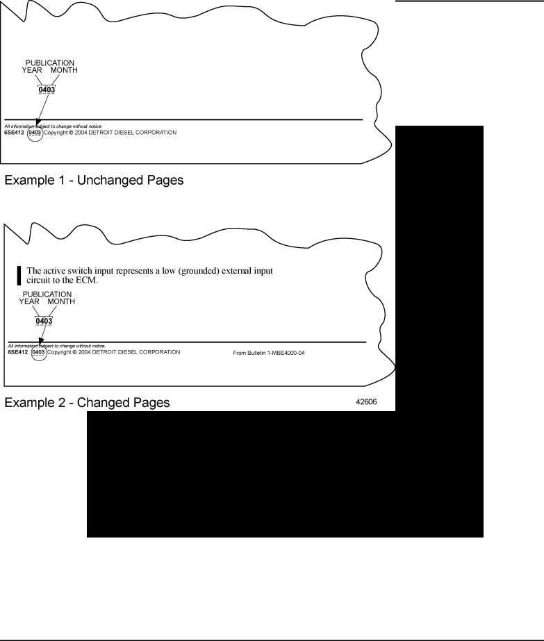
Revisions to this manual will be sent marked with a revision bar (see Example 2). Sections containing revisions will have a third line in the page footer (compare Examples 1 and 2).
ENGINE EXHAUST
Consider the following before servicing engines:
All information subject to change without notice.
6SE412 0403 Copyright © 2004 DETROIT DIESEL CORPORATION |
i |
MBE 4000 SERVICE MANUAL
PERSONAL INJURY
Diesel engine exhaust and some of its constituents are known to the State of California to cause cancer, birth defects, and other reproductive harm.
Always start and operate an engine in a well ventilated area.
If operating an engine in an enclosed area, vent the exhaust to the outside.
Do not modify or tamper with the exhaust system or emission control system.
All information subject to change without notice.
ii |
6SE412 0403 Copyright © 2004 DETROIT DIESEL CORPORATION |

MBE 4000 SERVICE MANUAL
TABLE OF CONTENTS
|
GENERAL INFORMATION ...................................................................... |
1 |
|
SCOPE AND USE OF THIS MANUAL ..................................................... |
3 |
|
GENERAL DESCRIPTION ...................................................................... |
3 |
|
ELECTRONIC ENGINE CONTROL SYSTEM ......................................... |
4 |
|
ENGINE BRAKING POWER .................................................................... |
7 |
|
GENERAL SPECIFICATIONS AND ENGINE VIEWS ............................. |
7 |
|
ENGINE MODEL AND SERIAL NUMBER ............................................... |
14 |
|
EXHAUST GAS RECIRCULATION (EGR) SYSTEM ............................... |
16 |
|
SAFETY INSTRUCTIONS AND PRECAUTIONS .................................... |
20 |
|
ENGLISH TO METRIC CONVERSION .................................................... |
32 |
|
DECIMAL AND METRIC EQUIVALENTS ................................................ |
33 |
|
TORQUE SPECIFICATIONS ................................................................... |
35 |
1 |
ENGINE |
|
1.1 |
CYLINDER HEAD COVER ...................................................................... |
1-3 |
1.2 |
CYLINDER HEAD .................................................................................... |
1-5 |
1.3 |
CYLINDER BLOCK .................................................................................. |
1-24 |
1.4 |
EGR CYLINDER HEAD AND BLOCK ..................................................... |
1-40 |
1.5 |
EGR FRONT AND REAR LIFTER BRACKETS ....................................... |
1-43 |
1.6 |
ENGINE BRAKE ...................................................................................... |
1-45 |
1.7 |
FRONT RADIAL SEAL ............................................................................. |
1-51 |
1.8 |
REAR RADIAL SEAL ............................................................................... |
1-54 |
1.9 |
CRANKSHAFT ASSEMBLY ..................................................................... |
1-57 |
1.10 |
FRONT COVER HOUSING ..................................................................... |
1-82 |
1.11 |
CRANKSHAFT VIBRATION DAMPER ..................................................... |
1-84 |
1.12 |
FLYWHEEL .............................................................................................. |
1-86 |
1.13 |
RING GEAR ............................................................................................. |
1-96 |
1.14 |
PILOT BEARING ...................................................................................... |
1-100 |
1.15 |
ENGINE CRANKING TOOL ..................................................................... |
1-102 |
1.16 |
FLYWHEEL HOUSING ............................................................................. |
1-104 |
1.17 |
PISTON, PISTON RING, AND CONNECTING ROD ............................... |
1-106 |
1.18 |
EGR PISTON, PISTON RING, AND CONNECTING ROD ...................... |
1-135 |
1.19 |
VALVES .................................................................................................... |
1-138 |
1.20 |
EGR VALVES ........................................................................................... |
1-161 |
1.21 |
ROCKER ARM ......................................................................................... |
1-166 |
1.22 |
CAMSHAFT AND CAMSHAFT SENSOR ................................................ |
1-170 |
1.23 |
EGR CAMSHAFT ..................................................................................... |
1-181 |
1.A |
ADDITIONAL INFORMATION .................................................................. |
1-183 |
2 |
FUEL SYSTEM |
|
2.1 |
INJECTOR UNIT PUMP ........................................................................... |
2-3 |
2.2 |
EGR INJECTOR UNIT PUMP .................................................................. |
2-11 |
2.3 |
FUEL INJECTOR LINE ............................................................................ |
2-13 |
All information subject to change without notice.
6SE412 0403 Copyright © 2004 DETROIT DIESEL CORPORATION |
iii |

MBE 4000 SERVICE MANUAL
2.4 |
FUEL INJECTOR NOZZLE ...................................................................... |
2-18 |
2.5 |
EGR FUEL INJECTOR NOZZLE ............................................................. |
2-24 |
2.6 |
PROTECTIVE SLEEVE ........................................................................... |
2-25 |
2.7 |
DDEC ELECTRONIC CONTROL UNIT ................................................... |
2-29 |
2.8 |
FUEL HEAT EXCHANGER ...................................................................... |
2-34 |
2.9 |
FUEL FILTER ........................................................................................... |
2-37 |
2.10 |
EGR FUEL FILTER .................................................................................. |
2-41 |
2.11 |
FUEL PUMP ............................................................................................. |
2-43 |
2.12 |
FUEL SYSTEM INSPECTION ................................................................. |
2-47 |
2.A |
ADDITIONAL INFORMATION .................................................................. |
2-57 |
3 |
LUBRICATION SYSTEM |
|
3.1 |
OIL PAN ................................................................................................... |
3-3 |
3.2 |
OIL SPRAY NOZZLE ............................................................................... |
3-9 |
3.3 |
EGR CAMSHAFT LUBRICATION SPRAYER .......................................... |
3-13 |
3.4 |
OIL PUMP ................................................................................................ |
3-14 |
3.5 |
EGR OIL PUMP AND PICK UP TUBE ..................................................... |
3-21 |
3.6 |
OIL FILTER .............................................................................................. |
3-23 |
3.7 |
OIL HEAT EXCHANGER AND FILTER HOUSING .................................. |
3-26 |
3.8 |
OIL PRESSURE AND TEMPERATURE SENSOR .................................. |
3-32 |
3.A |
ADDITIONAL INFORMATION .................................................................. |
3-35 |
4 |
COOLING SYSTEM |
|
4.1 |
COOLING SYSTEM ................................................................................. |
4-3 |
4.2 |
COOLANT PUMP .................................................................................... |
4-8 |
4.3 |
EGR COOLANT PUMP ............................................................................ |
4-20 |
4.4 |
FRONT IDLER AND TENSIONER SUPPORT ........................................ |
4-22 |
4.5 |
THERMOSTAT ......................................................................................... |
4-25 |
4.6 |
EGR THERMOSTAT HOUSING ............................................................... |
4-30 |
4.7 |
COOLANT TEMPERATURE SENSOR .................................................... |
4-32 |
4.A |
ADDITIONAL INFORMATION .................................................................. |
4-35 |
5 |
FUEL, LUBRICATING OIL, AND COOLANT |
|
5.1 |
FUEL ........................................................................................................ |
5-3 |
5.2 |
LUBRICATING OIL ................................................................................... |
5-5 |
5.3 |
COOLANT ................................................................................................ |
5-7 |
5.A |
ADDITIONAL INFORMATION .................................................................. |
5-13 |
6 |
AIR INTAKE SYSTEM |
|
6.1 |
INTAKE MANIFOLD ................................................................................. |
6-3 |
6.2 |
CHARGE PRESSURE/TEMPERATURE SENSOR ................................. |
6-5 |
6.3 |
TURBOCHARGER ................................................................................... |
6-6 |
6.A |
ADDITIONAL INFORMATION .................................................................. |
6-17 |
7 |
EXHAUST SYSTEM |
|
7.1 |
EXHAUST MANIFOLD ............................................................................. |
7-3 |
7.2 |
EXHAUST BRAKE ASSEMBLY ............................................................... |
7-6 |
7.3 |
EGR EXHAUST MANIFOLD .................................................................... |
7-14 |
7.4 |
EGR COOLER AND COOLER SUPPORT BRACKET ............................ |
7-26 |
7.5 |
EGR CONTROL VALVE, GAS OUTLET PIPE, AND GAS MIXER .......... |
7-43 |
All information subject to change without notice.
iv |
6SE412 0403 Copyright © 2004 DETROIT DIESEL CORPORATION |

MBE 4000 SERVICE MANUAL
7.6EPV (ELECTRONIC PROPORTIONAL VALVE) AND WABCO® AIR
|
SOLENOID VALVE ................................................................................... |
7-51 |
7.7 |
HENGST® BREATHER FILTER ............................................................... |
7-55 |
7.A |
ADDITIONAL INFORMATION .................................................................. |
7-59 |
8 |
ELECTRICAL EQUIPMENT |
|
8.1 |
DRIVE BELTS .......................................................................................... |
8-3 |
8.A |
ADDITIONAL INFORMATION .................................................................. |
8-15 |
9 |
POWER TAKE-OFF |
|
9.1 |
POWER TAKE-OFF ................................................................................. |
9-3 |
10 |
SPECIAL EQUIPMENT |
|
10.1 |
AIR COMPRESSOR ................................................................................ |
10-3 |
10.A |
ADDITIONAL INFORMATION .................................................................. |
10-11 |
11 |
OPERATION AND VERIFICATION |
|
11.1 |
PREPARATION FOR A FIRST TIME START ........................................... |
11-3 |
11.2 |
STARTING THE ENGINE ......................................................................... |
11-7 |
11.3 |
RUNNING THE ENGINE .......................................................................... |
11-10 |
11.4 |
STOPPING THE ENGINE ........................................................................ |
11-12 |
12 |
ENGINE TUNE-UP |
|
12.1 |
VALVE LASH CHECKING ........................................................................ |
12-3 |
12.2 |
ADJUSTING VALVE LASH ....................................................................... |
12-10 |
13 |
PREVENTIVE MAINTENANCE |
|
13.1 |
SCHEDULED INTERVALS ....................................................................... |
13-3 |
14 |
ENGINE STORAGE |
|
14.1 |
PREPARING ENGINE FOR STORAGE ................................................... |
14-3 |
15 |
MECHANICAL TROUBLESHOOTING |
|
15.1TROUBLESHOOTING THE ELECTRONIC ENGINE CONTROL
SYSTEM .................................................................................................. |
15-3 |
15.2 GENERAL TROUBLESHOOTING ........................................................... |
15-4 |
INDEX ................................................................................................. |
Index-1 |
All information subject to change without notice.
6SE412 0403 Copyright © 2004 DETROIT DIESEL CORPORATION |
v |

MBE 4000 SERVICE MANUAL
All information subject to change without notice.
vi |
6SE412 0403 Copyright © 2004 DETROIT DIESEL CORPORATION |

GENERAL INFORMATION
Section |
Page |
SCOPE AND USE OF THIS MANUAL ....................................................... |
3 |
GENERAL DESCRIPTION ......................................................................... |
3 |
ELECTRONIC ENGINE CONTROL SYSTEM ............................................ |
4 |
ENGINE BRAKING POWER ....................................................................... |
7 |
GENERAL SPECIFICATIONS AND ENGINE VIEWS ................................ |
7 |
ENGINE MODEL AND SERIAL NUMBER ................................................. |
14 |
EXHAUST GAS RECIRCULATION (EGR) SYSTEM .................................. |
16 |
SAFETY INSTRUCTIONS AND PRECAUTIONS ....................................... |
20 |
ENGLISH TO METRIC CONVERSION ...................................................... |
32 |
DECIMAL AND METRIC EQUIVALENTS ................................................... |
33 |
TORQUE SPECIFICATIONS ...................................................................... |
35 |

MBE 4000 SERVICE MANUAL
All information subject to change without notice.
2 |
6SE412 0403 Copyright © 2004 DETROIT DIESEL CORPORATION |
MBE 4000 SERVICE MANUAL
SCOPE AND USE OF THIS MANUAL
This manual contains complete instructions on operation, adjustment (tune-up), preventive maintenance, and repair (including complete overhaul) for the MBE 4000 engine. This manual was written primarily for persons servicing and overhauling the engine. In addition, this manual contains all of the instructions essential to the operators and users. Basic maintenance and overhaul procedures are common to all MBE 4000 engines, and apply to all engine models.
This manual is divided into numbered sections. Section one covers the engine (less major assemblies). The following sections cover a complete system such as the fuel system, lubrication system, or air system. Each section is divided into subsections which contain complete maintenance and operating instructions for a specific engine subassembly. Each section begins with a table of contents. Pages and illustrations are numbered consecutively within each section.
Information can be located by using the table of contents at the front of the manual or the table of contents at the beginning of each section. Information on specific subassemblies or accessories within the major section is listed immediately following the section title.
GENERAL DESCRIPTION
The MBE 4000 Engine described in this manual is a water-cooled, four-stroke, direct injection diesel engine. The cylinders are arranged in line. Each cylinder has a separate fuel injection pump (unit pump) with a short injection line to the injection nozzle, which is located in the center of the combustion chamber. The unit pumps are attached to the crankcase and are driven from the camshaft. Each cylinder has two intake valves and two exhaust valves.
Charge-air cooling and an exhaust gas turbocharger are standard equipment on all MBE 4000 engines.
The engine has a fully electronic control system, which regulates the injection quantity and timing using solenoid valves, allowing extremely low-emission operation. The control system consists of an engine-resident pump and nozzle control unit (the DDEC-ECU) and a vehicle control unit (the DDEC-VCU). The two are connected by a proprietary datalink.
Engine braking is controlled by a pneumatically-operated exhaust brake on the turbocharger and by a constant-throttle system. For greater braking power, an optional turbo brake is available.
The cylinder block has integrated oil and water channels. The upper section of the cylinder bore is induction-hardened. The six individual cylinder heads are made of cast iron. The cylinder head gasket is an adjustment-free seal with rubber sealing elements.
The pistons are made of aluminum alloy with ring carriers and a shallow combustion chamber recess. The pistons are cooled by oil spray nozzles.
The crankshaft is precision-forged with seven main bearings and eight custom-forged counter weights, and a vibration damper at the front end.
The camshaft is made of induction-hardened steel and has seven main bearings. Each cylinder has cams for intake and exhaust valves and a unit pump.
The valves are controlled by mushroom tappets, pushrods, and rocker arms. The intake and exhaust valves are opened and closed by a valve-guided bridge.
All information subject to change without notice.
6SE412 0403 Copyright © 2004 DETROIT DIESEL CORPORATION |
3 |

MBE 4000 SERVICE MANUAL
There is a force-feed lubricating oil circuit supplied by a gear-type oil pump. This pump is positioned at the rear of the oil pan and driven by gears from the crankshaft. The oil heat exchanger is located near the front of the crankcase on the right-hand side near the turbocharger.
The gear-type fuel pump is located near the front of the crankcase on the left hand side. The pump is driven from the forward end of the camshaft.
The air compressor, with a power-steering pump attached, is driven by a gear on the camshaft.
The engine is cooled by a closed system using recirculated coolant; temperature is regulated automatically by a thermostat.
There are three drive belts, each with its own automatic belt tensioner. The alternator and coolant pump (and any other accessories) are driven by a main drive belt. The fan and the air conditioner compressor are each driven by their own drive belt.
ELECTRONIC ENGINE CONTROL SYSTEM
The engine is equipped with a fully electronic control system. Besides the engine and its related sensors, this system is composed of the DDEC-ECU, or engine control unit, and the DDEC-VCU, or vehicle control unit. The two control units are connected by a proprietary datalink through which all necessary data and information can be exchanged. The DDEC-VCU then broadcasts all information on the J1587 and J1939 datalinks, where it can be read by minidiag2, Nexiq™ Diagnostic Data Reader (DDR), or Detroit Diesel Diagnostic Link® (DDDL) PC software.
The DDEC-ECU monitors both the engine and the datalink. When a malfunction or other problem is detected, the system selects an appropriate response; for example, the emergency running mode may be activated.
All information subject to change without notice.
4 |
6SE412 0403 Copyright © 2004 DETROIT DIESEL CORPORATION |
MBE 4000 SERVICE MANUAL
DDEC-ECU — Engine-Resident Control Unit
The DDEC-ECU control unit is located on the left-hand side of the engine. See Figure 1. The DDEC-ECU processes the data received from the DDEC-VCU, for example the position of the accelerator pedal, engine brake, etc. These data are evaluated together with the data from the sensors on the engine, such as, charge and oil pressure and coolant and fuel temperature. The data is then compared to the characteristic maps or lines stored in the DDEC-ECU. From these data, quantity and timing of injection are calculated and the unit pumps are actuated accordingly through the solenoid valves.
Figure 1 DDEC-ECU Control Unit Location
NOTE:
To obtain a replacement DDEC-ECU, all the data given on the DDEC-ECU label are required.
All information subject to change without notice.
6SE412 0403 Copyright © 2004 DETROIT DIESEL CORPORATION |
5 |

MBE 4000 SERVICE MANUAL
DDEC-VCU — Vehicle Control Unit
The vehicle control unit (DDEC-VCU) communicates with other electronic control units installed on the vehicle over the J1587 datalink. See Figure 2. Within the DDEC-VCU, sets of data for specific applications are stored. These include idle speed, maximum running speed, and speed limitation.
Figure 2 Vehicle Control Unit (DDEC-VCU)
The DDEC-VCU receives data from the following sources:
The operator (accelerator pedal position, engine brake switch)
Other electronic control units (for example, the antilock brake system)
The DDEC-ECU control unit (data such as oil pressure and coolant temperature)
All information subject to change without notice.
6 |
6SE412 0403 Copyright © 2004 DETROIT DIESEL CORPORATION |

MBE 4000 SERVICE MANUAL
From these data, instructions are computed for controlling the engine and transmitted to the DDEC-ECU via the proprietary datalink. The DDEC-VCU controls various systems, for example, communications with the datalink, the engine brake, and the constant-throttle valves. If the engine control system detects a fault, the appropriate fault code is broadcast on the datalink
and can be read using minidiag2. When there is a fault, the code for the control unit reporting the fault can be read directly on the display.
ENGINE BRAKING POWER
Exhaust Brake/Constant-Throttle Valves
To increase braking performance, the engine is equipped with an exhaust brake on the turbocharger in conjunction with constant-throttle valves on the cylinder head.
NOTE:
The constant-throttle values are activated by engine oil pressure.
The exhaust back-pressure is used by the exhaust brake to increase braking performance.
Optional Turbo Brake
For high braking output, the MBE 4000 engine can be equipped with an optional turbo brake. The turbo brake increases the air mass flow through the engine to provide up to 600 brake horsepower. The turbo brake can be operated either manually or automatically, through the cruise control function.
Because the charge air pressure is maintained at a high level during braking, full throttle response is available immediately, if the operator desires it, without any turbo lag.
The turbo brake is maintenance-free, highly reliable, and adds virtually no weight to the engine.
GENERAL SPECIFICATIONS AND ENGINE VIEWS
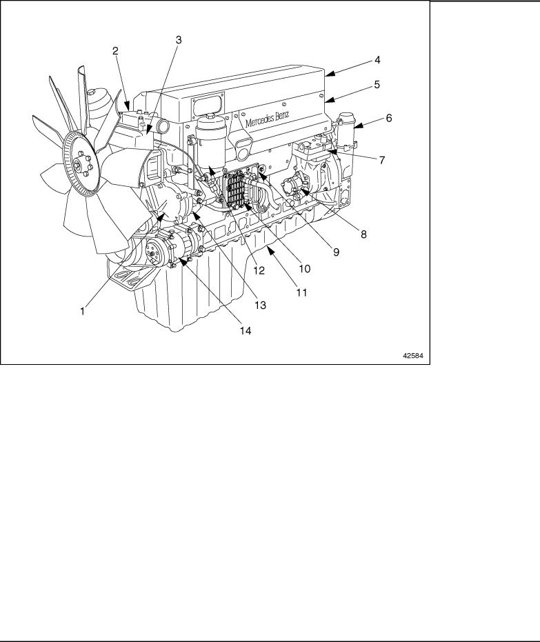
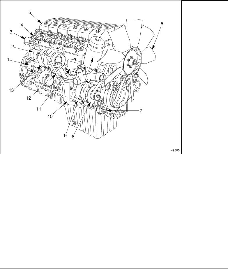
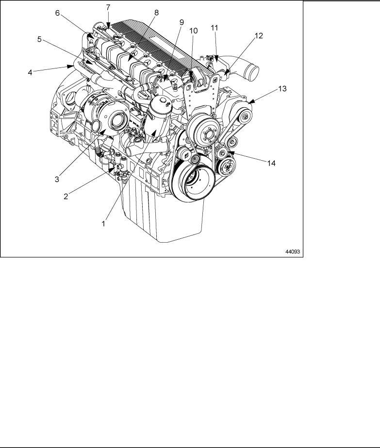
For a general view of the MBE 4000 engine, showing major components, see Figure 3 for the left-hand side, and see Figure 4 for the right-hand side.
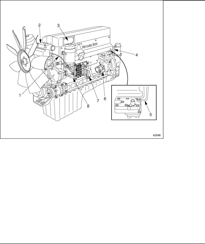
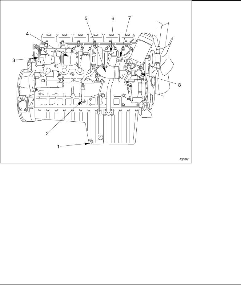
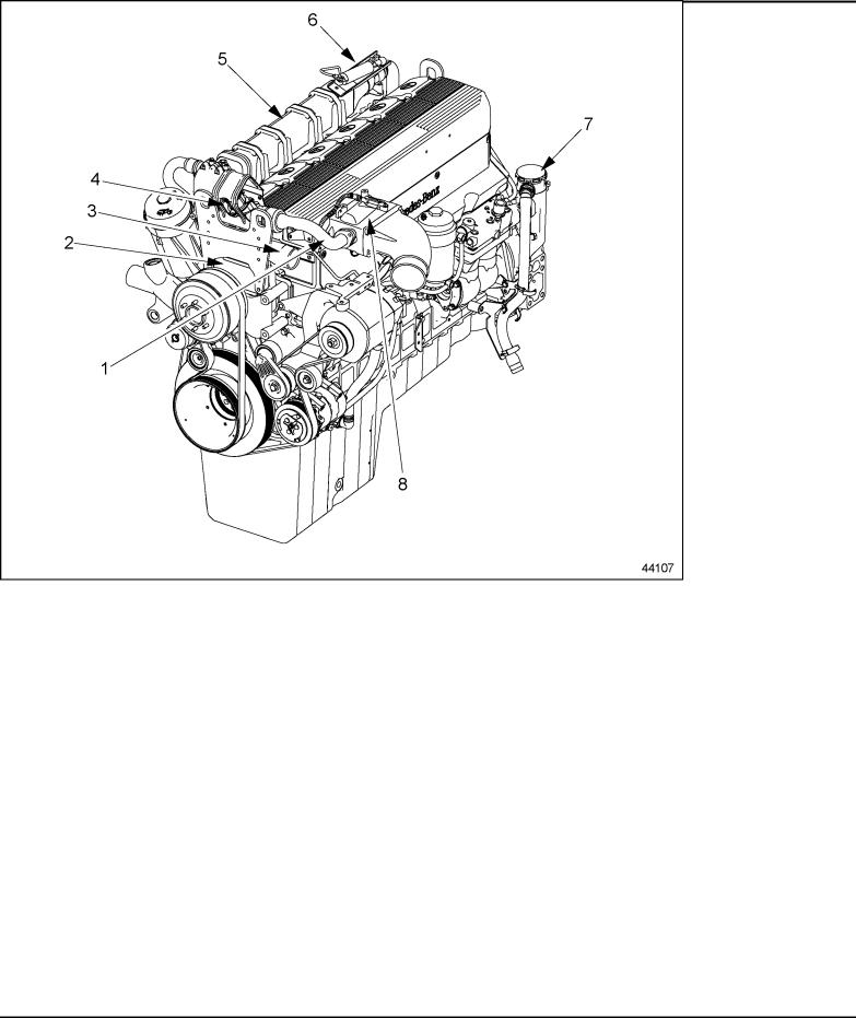
For a general view of the MBE 4000 engine, showing ports and fluid lines, see Figure 5 for the left-hand side and see Figure 6 for the right-hand side.
For a general view of the MBE 4000 engine, showing sensor locations, see Figure 7. Two sensors are not easily visible from the left-hand side of the engine: the charge pressure/temperature sensor, located on the right-hand side of the charge air manifold, and the oil pressure/temperature sensor located at the base of the oil filter.
All information subject to change without notice.
6SE412 0403 Copyright © 2004 DETROIT DIESEL CORPORATION |
7 |
MBE 4000 SERVICE MANUAL
|
|
|
|
1. |
Front Camshaft Cover |
8. Power Steering Pump |
|
2. |
Thermostat Housing |
9. DDEC-ECU Control Unit |
|
3. |
Coolant Pump |
10. |
Fuel Heat Exchanger |
4. |
Charge-Air (Intake) Manifold |
11. |
Oil Pan |
5. |
Engine Trim Cover |
12. |
Fuel Filter |
6. |
Crankcase Breather |
13. |
Fuel Pump |
7. |
Air Compressor |
14. |
Air Conditioner Compressor |
Figure 3 Left Side, Major Engine Components
All information subject to change without notice.
8 |
6SE412 0403 Copyright © 2004 DETROIT DIESEL CORPORATION |
MBE 4000 SERVICE MANUAL
|
|
|
|
1. |
Starter |
8. |
Alternator |
2. |
Exhaust Brake Valve |
9. |
Oil Filter |
3. |
Exhaust Brake Cylinder |
10. |
Oil Fill Tube |
4. |
Exhaust Manifold |
11. |
Oil Heat Exchanger |
5. |
Cylinder Head Cover |
12. |
Oil Dipstick |
6. |
Fan |
13. |
Turbocharger |
7. |
Belt Tensioner |
|
|
Figure 4 Right Side, Major Engine Components
All information subject to change without notice.
6SE412 0403 Copyright © 2004 DETROIT DIESEL CORPORATION |
9 |
MBE 4000 SERVICE MANUAL
|
|
|
|
1. |
Fuel Spill Line |
5. |
Coolant Line (to air compressor) |
2. |
Thermostat Outlet |
6. |
Hydraulic Line (to power steering pump) |
3. |
Charge Air Inlet |
7. |
Electronic Engine Harness Connector |
4. |
Open Breather Tube |
8. |
Fuel Feed Line |
Figure 5 Left Side, Ports and Lines
All information subject to change without notice.
10 |
6SE412 0403 Copyright © 2004 DETROIT DIESEL CORPORATION |
MBE 4000 SERVICE MANUAL
|
|
|
|
1. |
Oil Drain Plug |
5. |
Turbocharger Outlet Pipe |
2. |
Turbo Oil Return Line |
6. |
Dipstick |
3. |
Constant-Throttle Inlet |
7. |
Oil Fill Cap |
4. |
Exhaust Brake Valve Outlet |
8. |
Coolant Pump Inlet Pipe |
Figure 6 Right Side, Ports and Lines
All information subject to change without notice.
6SE412 0403 Copyright © 2004 DETROIT DIESEL CORPORATION |
11 |

MBE 4000 SERVICE MANUAL
1.Intake Manifold Pressure/Temperature Sensor
2.TDC Sensor (on camshaft)
3.Crank Angle Position Sensor
4.Coolant Temperature Sensor
Figure 7 Sensor Locations
5.Barometric Pressure Sensor (integrated into DDEC-ECU)
6.Fuel Temperature Sensor
7.Oil Pressure/Temperature Sensor
All information subject to change without notice.
12 |
6SE412 0403 Copyright © 2004 DETROIT DIESEL CORPORATION |
MBE 4000 SERVICE MANUAL
The general specifications for the MBE 4000 engine are listed in Table 1.
Description |
6–Cylinder Engines |
|
|
Engine Type |
Vertical, inline cylinder block with turbocharger and |
|
charge-air cooler |
|
|
Cooling System |
Liquid Circuit |
|
|
Combustion Principle |
4–Stroke direct-injection diesel |
|
|
Number of Cylinders |
6 |
|
|
Bore |
128 mm (5.03 in.) |
|
|
Stroke |
166 mm (6.53 in.) |
|
|
Displacement |
12.8 liters (781 in.3) |
Compression Ratio |
17.25:1 |
|
|
Starting Speed |
Approximately 100 rpm |
|
|
Direction of Engine Rotation (viewed from flywheel) |
Counterclockwise |
|
|
Starter |
Electric Motor |
|
|
Engine “Dry” Weight |
930 kg (2050 lb) |
|
|
Valve Lash (with engine cool) |
Intake = 0.40 mm (0.016 in.) |
|
|
|
Exhaust = 0.60 mm (0.024 in.) |
|
|
Valve Lift (at maximum valve clearance) |
Intake = 11.546 mm (0.45 in.) |
|
|
|
Exhaust = 11.963 mm (0.47 in.) |
|
|
Minimum Engine Oil Pressure |
At Idle rpm = 50 kPa (7 psi) |
|
|
|
At Maximum rpm = 250 kPa (36 psi) |
|
|
Fuel Injectors |
Minimum Opening Pressure = 27,500 kPa (3989 psi) |
|
|
|
Maximum Opening Pressure = 30,000 kPa (4350 psi) |
|
|
Coolant Thermostat |
Opening Temperature = 81 to 85 C (177 to 185 F) |
|
|
|
Normal Operating Temperature = 95 C (203 F) |
|
|
Table 1 General Technical Information
All information subject to change without notice.
6SE412 0403 Copyright © 2004 DETROIT DIESEL CORPORATION |
13 |
MBE 4000 SERVICE MANUAL
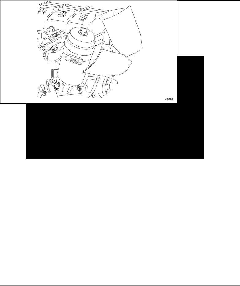
ENGINE MODEL AND SERIAL NUMBER
The engine model number and serial number are located on the engine type plate. It is located on the oil filter housing on the right-hand side of the engine. See Figure 8. The engine type reference and the complete engine serial number appear beside the name of the manufacturer. The engine type reference, OM 460 LA is the production code. The engine serial number contains the type reference followed by a sequential manufacturing number. See Figure 9.
Figure 8 Location of Engine Type Plate
All information subject to change without notice.
14 |
6SE412 0403 Copyright © 2004 DETROIT DIESEL CORPORATION |
MBE 4000 SERVICE MANUAL
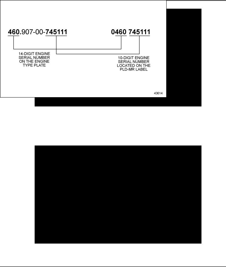
Figure 9 Engine Type Plate Detail
In addition to the fourteen-digit number on the engine type plate, there is a ten-digit number used for warranty and service that is found on the DDEC-ECU label. The ten-digit number is derived from the fourteen-digit number. See Figure 10.
Figure 10 Engine Serial Number
All information subject to change without notice.
6SE412 0403 Copyright © 2004 DETROIT DIESEL CORPORATION |
15 |
MBE 4000 SERVICE MANUAL
EXHAUST GAS RECIRCULATION (EGR) SYSTEM
The purpose of the Exhaust Gas Recirulation (EGR) system is to reduce engine exhaust gas emissions in accordance with EPA regulations.
The EGR system consists of:
EGR Cooler
EGR Control Valves
Reed Valves
EGR Charge Air Mixer
The MBE 4000 engines for on-highway EPA 2004 regulation applications use a cooled EGR system. Part of the exhaust gasses from the front three cylinders are routed from the
exhaust manifold through the EGR cooler, past control and reed valves, and are mixed with the intake manifold charge air. The addition of cooled exhaust gasses back into the combustion airflow reduces the peak in cylinder combustion temperature. Less oxides of nitrogen (NOx) are produced at lower combustion temperatures.
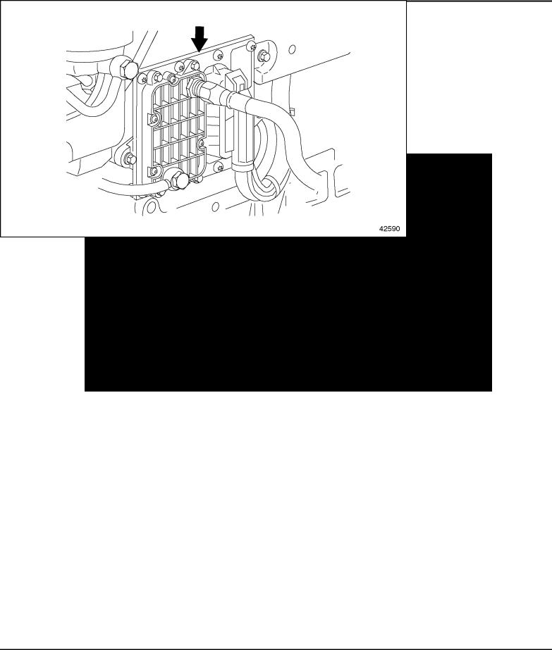
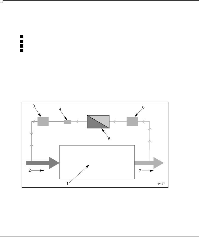
The recycled exhaust gasses are cooled before engine consumption in a tube and shell engine water cooler. See Figure 11.
1. |
Engine |
5. |
EGR Cooler |
2. |
Intake Air |
6. |
EGR Shutoff Valve |
3. |
EGR Modulated Valve |
7. |
Exhaust Air |
4. |
Reed Valves |
|
|
Figure 11 Air flow Diagram through Engine with EGR System
All information subject to change without notice.
16 |
6SE412 0403 Copyright © 2004 DETROIT DIESEL CORPORATION |
MBE 4000 SERVICE MANUAL
For an general view of the MBE 4000 engine with an EGR system, See Figure 12 for a right side view and see Figure 13 for a left side view.
|
|
|
|
|
1. |
Oil Filter |
8. |
EGR Cooler |
|
2. |
Solenoid Valve (Wabco®) |
9. |
Reed Valve Housing |
|
3. |
Turbocharger |
10. |
EGR Modulated Control Valve |
|
4. |
EGR Gas Inlet Pipe (Hot Pipe) |
11. |
EGR Mixer |
|
5. |
Exhaust Manifold |
12. |
EGR Gas Outlet Pipe (Cold Pipe) |
|
6. |
EGR Shutoff Valve |
13. |
Alternator |
|
7. |
EGR Air Cylinder |
14. |
Belt Tensioner |
|
Figure 12 EGR Engine with EGR Components and Revised Parts (Right View)
All information subject to change without notice.
6SE412 0403 Copyright © 2004 DETROIT DIESEL CORPORATION |
17 |
MBE 4000 SERVICE MANUAL
|
|
|
|
1. |
EGR Gas Outlet Pipe |
5. |
EGR Cooler |
2. |
Coolant Pump |
6. |
EGR Shutoff Valve (hidden) |
3. |
Thermostat Housing |
7. |
Crankcase Breather (Hengst filter) |
4. |
EGR Modulated Control Valve |
8. |
EGR Mixer |
Figure 13 EGR Engine with EGR Components and Revised Parts (Left View)
All information subject to change without notice.
18 |
6SE412 0403 Copyright © 2004 DETROIT DIESEL CORPORATION |

MBE 4000 SERVICE MANUAL
EGR Cooler
The EGR Cooler is equipped with a single-pass cooler. Part of the exhaust gasses from the first three cylinders are directed through the EGR shutoff valve and through the cooler and reed valves, past the EGR modulated control valve and the mixer and then back to the cylinder.
EGR Control Valves
There are two EGR valves on the MBE 4000 EGR engine — the EGR shutoff valve and the EGR modulated control valve. The EGR shutoff valve is a pneumatically driven butterfly valve, located at the inlet of the EGR cooler. It closes when the exhaust flap or turbo-brake actuates, avoiding exhaust gas flow and excessive pressure in the EGR cooler and reed valves. The EGR modulated control valve is an electronically actuated butterfly valve located after the EGR cooler and reed valves, controlled by the DDEC-ECU (formerly PLD-MR). This valve controls the exhaust gas flow for the intake manifold.
Reed Valves
The reed valves work like a check valve, allowing flow of gas only in one direction, avoiding gas back flow when the intake pressure is higher than exhaust gas pressure. As the average exhaust pressure is lower than the intake pressure, the gas flow through the reed valves is possible due to exhaust gas pressure peaks — peaks slightly higher than the intake air pressure, which occur as the engine exhaust valves open. During this peak of pressure, the reed valves open and allow gas flow to the EGR modulated valve and mixer.
EGR Mixer
The purpose of the mixer is to ensure good mixing of the cooled EGR gasses with filtered charge air. Once the exhaust gasses are cooled and have completed their cycle through the EGR system, they are released into the EGR mixer. The recycled exhaust gasses are combined with the charged air and directed to the cylinders.
All information subject to change without notice.
6SE412 0403 Copyright © 2004 DETROIT DIESEL CORPORATION |
19 |

MBE 4000 SERVICE MANUAL
SAFETY INSTRUCTIONS AND PRECAUTIONS
The following safety measures are essential when working on the MBE 4000 engine.
To reduce the chance of personal injury and/or property damage, the following instructions must be carefully observed:
Proper service and repair are important to the service technician and the safe, reliable operation of the engine. If part replacement is necessary, the part must be replaced with one of the same part number or with an equivalent part number. Do not use a replacement part of lesser quality.
The service procedures recommended and described in this manual are effective methods of performing repair. Some of these procedures require the use of specially designed tools.
Accordingly, anyone who intends to use a replacement part, procedure or tool that is not recommended, must first determine that neither personal safety nor the safe operation of the engine will be jeopardized by the replacement part, procedure or tool selected.
It is important to note that this manual contains various “Cautions” and “Notices” that must be carefully observed in order to reduce the risk of personal injury during repair or the possibility that improper repair may damage the engine or render it unsafe. It is also important to understand that these “Cautions” and “Notices” are not exhaustive, because it is impossible to warn personnel of the possible hazardous consequences that might result from failure to follow these instructions.
All information subject to change without notice.
20 |
6SE412 0403 Copyright © 2004 DETROIT DIESEL CORPORATION |
MBE 4000 SERVICE MANUAL
Exhaust (Start/Run Engine)
Before starting and running an engine, adhere to the following safety precautions:
PERSONAL INJURY
To avoid injury before starting and running the engine, ensure the vehicle is parked on a level surface, parking brake is set, and the wheels are blocked.
PERSONAL INJURY
Diesel engine exhaust and some of its constituents are known to the State of California to cause cancer, birth defects, and other reproductive harm.
Always start and operate an engine in a well ventilated area.
If operating an engine in an enclosed area, vent the exhaust to the outside.
Do not modify or tamper with the exhaust system or emission control system.
Stands
Safety stands are required in conjunction with hydraulic jacks or hoists. Do not rely on either the jack or the hoist to carry the load. When lifting an engine, ensure the lifting device is fastened securely. Ensure the item to be lifted does not exceed the capacity of the lifting device.
PERSONAL INJURY
To avoid injury when removing or installing a heavy engine component, ensure the component is properly supported and securely attached to an adequate lifting device to prevent the component from falling.
All information subject to change without notice.
6SE412 0403 Copyright © 2004 DETROIT DIESEL CORPORATION |
21 |
MBE 4000 SERVICE MANUAL
Glasses
Select appropriate safety glasses for the job. It is especially important to wear safety glasses when using tools such as hammers, chisels, pullers or punches.
PERSONAL INJURY
To avoid injury when working on or near an operating engine, wear protective clothing, eye protection, and hearing protection.
Work Place
Organize your work area and keep it clean. A fall could result in a serious injury. Eliminate the possibility of a fall by:
Wiping up oil spills
Keeping tools and parts off the floor
After servicing or adjusting the engine:
Reinstall all safety devices, guards or shields
Ensure that all tools and servicing equipment are removed from the engine
All information subject to change without notice.
22 |
6SE412 0403 Copyright © 2004 DETROIT DIESEL CORPORATION |
 Loading...