


 Loading...
®
TECHNICIAN GUIDE
SERIES 4000 COMMON RAIL
FUEL SYSTEM
ATTENTION
This bulletin is a guideline for qualified personnel. The information contained in this bulletin may not be complete and is subject to change without notice.
Cautions
WORK SAFELY
!CAUTION:
The service procedures recommended by Detroit Diesel Corporation and described in this Technicians Guide are effective methods of performing service and repairs. Some of these procedures require the use of tools specially designed for this purpose.
Accordingly, anyone who intends to use a replacement part, service procedure or tool which is not recommended by Detroit Diesel Corporation must first determine that neither their safety nor the safe operation of the engine will be jeopardized by the replacement part, service procedure or tool selected.
This Technician’s Guide contains various work procedures that must be carefully observed in order to reduce the risk of personal injury during service or repair or the possibility that improper service or repair may damage the engine or render it unsafe. It is also important to understand that these work
procedures are not exhaustive, because it is impossible for Detroit Diesel Corporation to warn of all the possible hazardous consequences that might result from failure to follow these instructions.
A service technician can be severely injured if caught in the pulleys, belts or rotating parts of an engine that is accidentally started. To avoid personal injury, take this precaution before starting to work on an engine:
Disconnect the battery from the starting system by removing one or both of the battery cables (disconnect negative [ground] cable first). With the electrical circuit disrupted, accidental contact with the starter button will not produce an engine start.
Follow all lockout procedures as required.
i
Cautions
SAFETY PRECAUTIONS TO OBSERVE WHEN
WORKING ON THE ENGINE
1.Consider the hazards of the job and wear protective gear such as safety glasses, safety shoes, hard hats, hearing protection, etc. to provide adequate protection.
2.When using a lifting device, make sure the lifting device is fastened securely. Be sure the item to be lifted does not exceed the capacity of the lifting device.
3.Always use caution when using power tools.
4.When using compressed air to clean a component, such as flushing a radiator or cleaning an air cleaner element, use a safe amount of air. Too much air can rupture or in some other way damage a component and create a hazardous situation that can lead to personal injury. Always wear adequate eye protection (safety glasses, safety face shield) when working with compressed air.
5.To avoid possible personal injury when working with chemicals, steam and/or hot water, wear adequate protective clothing (face shield, rubber apron, gloves, boots, etc.) work in a well ventilated area, and exercise caution.
6.Avoid the use of carbon tetrachloride, carbon dissolved, methylene, chloride, perchloroethylene and trichloroethylene
as cleaning agents because of harmful vapors they release. Use 1.1.1 – trichlorethane.
However, while less toxic than other chlorinated solvents, use it with caution. Be sure the work area is adequately ventilated and wear protective gloves, goggles or face shield and an apron. Follow chemical manufacturer’s use and safety recommendations.
Mineral spirits or mineral spirits based solvents are highly flammable. They must be stored and used in “No Smoking” areas away from sparks and open flames.
7.Do not weld on or near the diesel fuel tank until it has been thoroughly emptied and ventilated. Possible explosion could result if this precaution is not taken.
8.Failure to inspect parts thoroughly before installation, failure to install the proper parts or failure to install parts properly can result in component or engine mal-function and/or damage and may also result in personal injury.
9.When working on an engine that is running, accidental contact with the hot exhaust manifolds or turbochargers can cause severe burns. Avoid making contact across the two terminals of a battery, which can result in severe arcing.
10.Turbocharger air inlet shields should be used if operation of the turbocharger is necessary without normal piping, to avoid injury.
ii
Series 4000 Fuel System Technician Guide
Table of Contents
|
|
Page |
INTRODUCTION |
1 |
|
SAFETY |
|
1 |
DESCRIPTION OF FUEL SYSTEM |
3 |
|
COMMON RAIL FUEL SYSTEM OPERATION |
5 |
|
DETROIT DIESEL ELECTRONIC CONTROL (DDECIV) |
9 |
|
COMPONENT REVIEW (INDEX) |
15 |
|
• |
HIGH-PRESSURE FUEL PUMP |
17 |
• LOW-PRESSURE DELIVERY FUEL PUMP |
25 |
|
• |
ELECTRONIC UNIT INJECTOR |
31 |
• FUEL RAILS AND LINES |
37 |
|
• |
FLOW LIMITER VALVES |
53 |
• C&I FUEL JUNCTION BLOCK AND SECONDARY FILTERS |
57 |
|
• MARINE SECONDARY FUEL FILTERS |
61 |
|
• ECM COLD PLATE (S) |
63 |
|
• FUEL LEAK MONITOR SYSTEM (MARINE) |
65 |
|
• |
DDEC SENSORS |
67 |
FUEL SYSTEM PLUMBING REQUIREMENTS |
68 |
|
DAVCO FUEL PRO FILTERS |
70 |
|
FUEL SYSTEM PRIMING PROCEDURE |
72 |
|
FUEL SYSTEM TROUBLE SHOOTING |
74 |
|
TORQUE SPECIFICATIONS FOR FUEL SYSTEM COMPONENTS |
78 |
|
SERVICE PUBLICATIONS |
80 |
|
NOTES |
|
|
Series 4000 Fuel System Technician Guide
INTRODUCTION
The purpose of a properly designed fuel system is to provide clean fuel, free from air, water or dirt, and to deliver fuel to the engine at correct amounts for good combustion to provide optimum power, fuel economy and emissions compliance.
A unique feature of the Series 4000 is the common rail fuel injection system. This system relies on a single high-pressure fuel pump that provides a continuous supply of fuel, at injection pressure, to all of the injectors at all times. This common rail fuel system does not require cam driven unit injectors or injection pumps with separate cam driven plungers to make fuel pressure for each injector. The unit injectors in the Series 4000 common rail fuel system do not make fuel pressure. DDECIV Electronics alone control injector timing, the amount of fuel and atomization of fuel being supplied from the high-pressure rails. The Common Rail Fuel System provides the Series 4000 with the most advanced fuel system technology available today.
The Common Rail Fuel System consists of many unusual components not found in other diesel fuel systems. Therefore, the Fuel System Technician Guide is intended to help better understand the Common Rail Fuel System operation and components as well as provide failure analysis to properly maintain this unique system for maximum performance.
This manual is applicable to all engine sizes and product applications of the Series 4000 and is intended to be expanded upon, as additional information becomes available. It is also a good place for the technician to add helpful notes on the fuel system for future reference.
SAFETY
Safety is always our first concern. To guard against safety mishaps while working on the common rail fuel system, there are a couple of areas of caution to be noted:
The common rail fuel system operates at pressures up to 19.6 KPSI (19,000 PSI). Fuel at this pressure can be very hazardous causing bodily injury or fire if proper repair procedures are not followed. Fuel under high pressure creates a very fine spray, which can penetrate the skin or cut! Appropriate safety equipment should be worn to prevent injury. NEVER ATTEMPT REPAIRS OF HIGHPRESSURE FUEL LEAKS WHILE AN ENGINE IS IN OPERATION!
Under certain conditions the high-pressure fuel lines from the high-pressure fuel rail to the injectors can become heated from combustion gases. Care should be taken to prevent the possibility of burns from excessive contact with theses fuel lines.
Page 1
Page 2

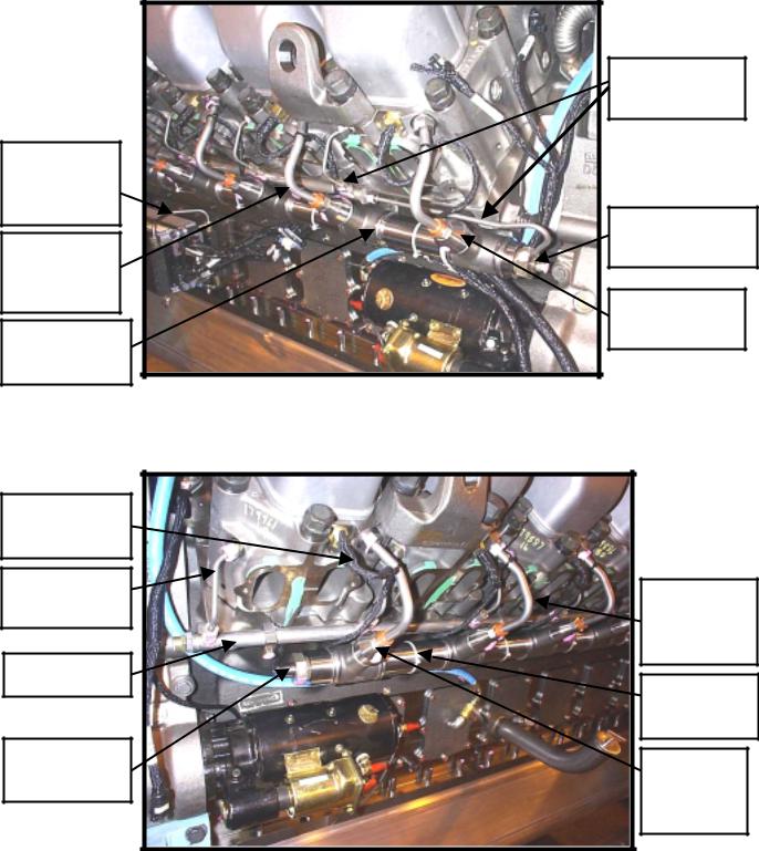
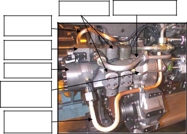
Description of Fuel System
Common Rail Fuel System - A Bank
FUEL RETURN RAIL
HIGH-PRESSURE FUEL LINE TO B BANK RAIL
HIGH-PRESSURE FUEL
PUMP CONTROLLER SOLENOID
HIGH-PRESSURE
FUELPR SSUREPUMP
LOW-PRESSURE FUEL SUPPLY LINE FROM FUEL JUNCTION BLOCK TO HP PUMP CONTROL SOLENOID
HIGH PRESSURE |
INJECTOR FUEL |
LINE |
HIGH-PRESSURE |
FUEL RAIL |
FLOW LIMITER |
VALVE LOCATION |
ECM COLD |
PLATE (S) |
FUEL JUNCTION |
BLOCK AND |
FILTER ADAPTOR |
Fig. 1
HIGH-PRESSURE FUEL |
LOW-PRESSURE FUEL DELIVERY PUMP |
LINE TO A BANK RAIL |
HIGH-PRESSURE PUMP CONTROL SOLENOID
DDEC CONNECTION TO HIGH-PRSSURE PUMP CONTROL SOLENOID
LOW-PRESSURE FUEL SUPPLY TO HP PUMP
HP PUMP RETURN FUEL TO FUEL JUNCTION BLOCK
HIGH-PRESSURE FUEL LINE TO A BANK RAIL
Fuel Delivery System - A Bank
Fig. 2
Page 3
RETURN FUEL RAIL
HIGHPRESSURE FUEL RAIL CONNECTOR
FUEL JUNCTION BLOCK
LOWPRESSURE DELIVERY FUEL PUMP
ECM COLD PLATE CROSSOVER LINE
HIGHPRESSURE INJECTOR FUEL LINE
HIGHPRESSURE FUEL RAIL
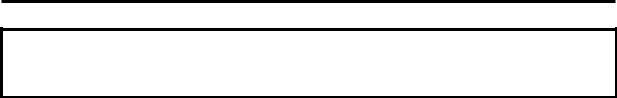
Description of Fuel System
High-pressure Rail - A Bank
|
FUEL RETURN |
|
LINES TO FUEL |
|
RETURN RAIL |
|
HIGH-PRESSURE |
|
RAIL RELIEF |
|
VALVE |
|
FLOW LIMITER |
|
VALVE |
|
LOCATION |
Rear of Engine |
Fig. 3 |
High-pressure Rail B Bank
DDEC WIRING |
|
|
HARNESS TO |
|
|
INJECTOR |
|
|
INJECTOR |
HIGH- |
|
FUEL RETURN |
||
PRESSURE |
||
LINE |
||
INJECTOR |
||
|
||
FUEL |
FUEL LINE |
|
|
||
RETURN RAIL |
HIGH- |
|
|
PRESSURE |
|
|
FUEL RAIL |
|
HIGH- |
FLOW |
|
PRESSURE |
||
LIMITER |
||
RAIL END |
||
VALVE |
||
|
||
|
LOCATION |
|
Rear of Engine |
Fig. 4 |
Page 4
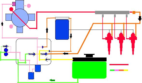
Common Rail Fuel System Operation
Limiter Safety
LP Common Rail Limiting Safety
Valve 19.6 KPSI
HP
Valve 1350 Bar
High |
Flow |
|
Pressure |
Limiter |
|
Pump |
||
|
LT
DDEC IV
ECM
6.8 Bar |
Fuel filter |
2.0 Bar |
|
||
|
Housing |
|
|
|
|
|
1.7 Bar |
|
|
|
.1 Bar |
Fuel filters
Injectors
Fuel Tank
H. Pr Line
L. Pr Line
Pro 40
Fig. 5
The Common Rail Fuel System used on the Series 4000 is a two-stage fuel distribution system. Gear driven fuel pumps maintain constant fuel supply pressure. This pressure is supplied to the common rails then to all injectors. Constant high-pressure is available regardless of crankshaft position or engine speed.
The first stage is the fuel transfer side which brings fuel from the fuel tank, through the filters, and provides low-pressure fuel supply of 65 PSI at idle to 85 PSI at full load to the second stage high pressure system. Additionally, low-pressure fuel is sent to the ECM Cold Plates to protect the ECM's from excessive heat (Refer to page 63). An OEM supplied fuel cooler should be incorporated in the fuel system to assist the cooling function for the ECM’s. Additionally, low-pressure fuel is used for cooling and lubrication in the high-pressure fuel pump. However, unlike other fuel systems, fuel temperature has no affects on engine power or performance due to the extremely high fuel operating pressure, which prevents the fuel from boiling and vaporizing.
The high-pressure system receives the low-pressure fuel at the control regulator and further pressurizes it in the high-pressure pump from (8.3 KPSI at idle to 17.4 KPSI) for non-low flow injectors and (7.25KPSI at idle to 13.1KPSI) for low flow injectors at maximum load conditions to the high-pressure rails. (Refer to page 17). Fuel pressure at Full No-Load averages about 11.4 KPSI. A 19.6 KPSI safety-relief valve on the A-bank rail protects the fuel system components from damage due to excessive pressure.
Page 5
Common Rail Fuel System Operation
High-pressure fuel as received at each injector provides lubrication and cooling of the injectors while awaiting the DDECIV signal from the ECM’s to the injector solenoid to start the injection event. Approximately 90% of the fuel received at the injectors is injected into the engine cylinder for combustion, while 10% of the fuel is returned to the fuel tank under full load conditions.
Washer
C-E Ring
Inlet Filter 
Retaining Nut
Fig. 6
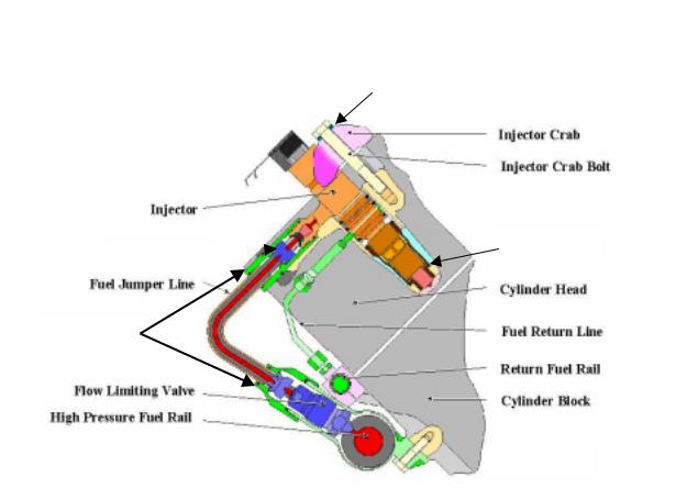
CROSS SECTION VIEW OF FUEL SYSTEM AT CYLINDER HEAD
The high-pressure fuel rails provide continuous pressure at all times to all injectors within the engine. The high-pressure fuel rail at each cylinder location is a port, which is fitted with a flow-limiter valve. High-pressure fuel passes from the stainless steel high-pressure rails through flow limiter valves to the injectors. The flow limiter valves operate by sensing fuel flow differential, which can shut off the flow of fuel to prevent excessive over fueling of a cylinder in the event of a faulty injector (Refer to page 53).
All of the joints from the high-pressure rail to the flow limiter valves to the injectors are conical shaped metal-to-metal sealing (Refer to page 37).
Page 6

Common Rail Fuel System Operation
The high-pressure fuel line to the injectors is double walled with an air gap between the stainless steel inner tube and the outer copper protective tube (Refer to page 44). This air gap is also a vent from the injector providing early warning of poor injector C-E Ring sealing. The injector has a vent hole drilled in the body from below the lower O-ring land out through the injector arm to the high-pressure line joint surface, which aligns with the air gap in the high-pressure fuel line (Refer to page 31).
The injector is retained in the cylinder head hole tube by the injector hold down clamp and retaining bolt. The clamp load provided by this hold down crab and bolt works with the C-E Ring located at the injector nozzle to provide a compression seal with the injector hole tube inner surface. The high-pressure injector fuel line fittings are held in position to the tube by retaining nuts on each end (Refer to page 44). These retaining nuts have reverse threads, which requires a special tool for installation.
At the inlet of the injector, recessed in the arm, is an inlet filter screen. This screen is a safety element intended to trap foreign material, which could find its way to the injector. The injector assembly has three O-ring seals between the injector body and the cylinder head to control the flow of the return fuel from the injector into the cylinder head return passage (Refer to page 31). Unused fuel from the injector exits the injector through the passage between the second and third O- ring land into the return port in the cylinder head. The return fuel then passes through the external return fuel line from the cylinder head to the return fuel rail back to the fuel tank.
Cylinder Head View
VALVE OPERATING
MECHANISM
ELECTRONIC UNIT
INJECTOR
DDEC WIRING
HARNESS TO
INJECTOR HIGH-PRESSURE FUEL LINE TO
INJECTOR
RETURN FUEL
LINE
Fig. 7 Injector Installation in Cylinder Head
Page 7
Page 8
Detroit Diesel Electronic Controls
|
Rail |
|
Pressure |
|
Pressure |
Common Rail |
Limiting |
|
Sensor |
Valve |
|
|
Flow |
|
|
|
Limiter |
|
|
Fuel Tank |
|
|
|
|
|
|
Injectors |
Filter |
|
MDEC |
|
|
|
DDECORIV |
|
Controlled High |
|
ECM |
|
|
DDECI |
|
|
Pressure Pump with |
Sensors |
V |
|
Pre-Supply Pump |
|
Fig. 8
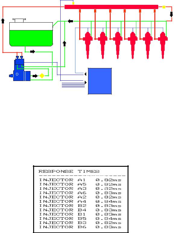
DDECIV electronics control the beginning of injection or timing of the event and the duration of the injection event, which determines the amount of fuel being injected. Timing of the injection event is totally a function of DDECIV and not that of the camshaft lobe profile as in other fuel systems.
DDECIV sends a signal to the injector solenoid to inject fuel into the cylinders. To provide this control, DDECIV electronics utilize state of the art microprocessors to gather information from the engine and its operating environment to be used in determining the optimum schedule of fuel injection. Part of the information gathered is from the fuel system itself. DDECIV receives feedback for the injector solenoids as to their performance in the form of Response Times as seen in the DDEC printout shown in Fig. 9.
Fig. 9 Injector Response Times Printout.
Page 9
Detroit Diesel Electronic Controls
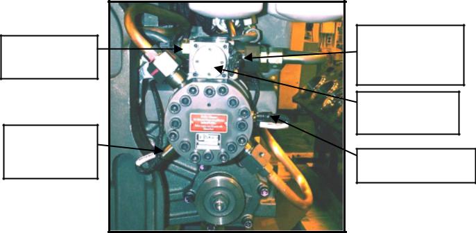
The Common Rail Fuel System consists of several sensors used to evaluate its own performance. These sensors are; high fuel pressure, low fuel pressure and fuel temperature, which are located on the high-pressure fuel pump as shown in Fig. 10.
The low fuel pressure sensor provides information on the availability of lowpressure fuel being supplied to the high-pressure pump. The high fuel pressure sensor provides information on the fuel pressure within the high-pressure rails available for injection. The fuel temperature sensor provides information on the temperature of the fuel being supplied to protect the ECM’s and high-pressure fuel pump.
HIGH-PRESSURE FUEL PUMP
LOW-PRESSURE FUEL PRESSURE SENSOR
HIGH-PRESSURE FUEL RAIL PRESSURE SENSOR
DDEC HARNESS CONNECTION TO HP PUMPCONTROL SOLENOID (24VOLT SUPPLY)
HIGH-PRESSURE PUMP CONTROL SOLENOID
FUEL TEMPERATURE SENSOR
Fig. 10 High-pressure Pump Sensor Locations.
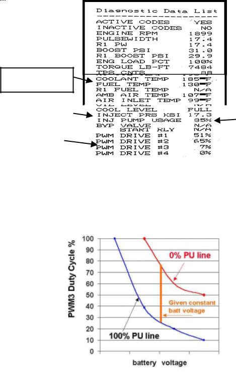
The high-pressure fuel pump receives low-pressure fuel from the fuel delivery pump and controls the high-pressure fuel output with the control solenoid, which receives input from the Master ECM and provides feedback information to the Master ECM. This input and output can be read with a DDR as PWM3 and Injection Pump Usage (Refer to Fig. 11).
The normal PWM3 operating range is 8-52%. Injection pump usage operates between 2% and 98% range. The normal injection pump usage at 100% engine load is in the 45-65% range at 1900 RPM. The control solenoid operates on 24 Volts DC with a fuse located in the OEM supplied power circuit.
Page 10
Detroit Diesel Electronic Controls
FUEL
TEMPERATURE
INJECTION RAIL |
|
|
|
|
|
|
HIGH- |
||
|
|
||||||||
PRESSURE |
|
|
|
|
|
|
PRESSURE |
||
|
|
|
|
|
|
|
|
|
PUMP USAGE |
|
|
|
|
|
|
|
|
||
|
|
|
|
|
|
|
|||
PWM #3 |
|
|
|
|
|
|
|
||
|
|
|
|
|
|
||||
PERCENTAGE |
|
|
|
|
|
|
|
||
|
|
|
|
|
|
|
|
|
|
|
|
|
|
|
Fig. 11 Diagnostic Data List Printout. |
|
|
|
|
|
|
|
|
|
|
|
|
|
|
|
|
|
|
|
|
|
|
|
|
Fig. 12 Relationship Between High-pressure Pump % (Percent) Usage and PWM3.
Page 11
Detroit Diesel Electronic Controls
ELECTRONIC PILOT INJECTION (EPI)
Normal fuel injection has long ignition delays resulting in large quantities of fuel to be injected before the beginning of combustion. With large amounts of fuel at the beginning of combustion, there is a high rate of cylinder pressure rise, white smoke from unburned fuel and excessive combustion noise.
DDEC controlled Electronic Pilot Injection (EPI) provides a small quantity of fuel injection in advance of the normal injection beginning the combustion process. This is followed by the main quantity of fuel injection to complete combustion. EPI is a form of indirect injection reducing the ignition delay period thereby reducing the rate of pressure rise effectively reducing the unburned fuel and cylinder knock during startup.
Significant reduction in fuel consumption, peak cylinder pressure, rate of pressure rise and emissions are all achieved with EPI.
HALF ENGINE IDLE
The half engine idle feature controlled by DDEC enables the engine to maintain higher cylinder temperature during idle to light load operating conditions. Half engine idle is activated depending on the percent of load, air intake temperature and engine coolant temperature. Half engine operation may occur up to 1900-rpm engine speed.
Half engine operation differs with the 12V4000 from the 16V4000 models on the 12V, only the master ECM fires the “A” bank cylinders; with the 16V, both ECM’s control (4) cylinders each for either bank randomly.
Page 12
Detroit Diesel Electronic Controls
Fig. 13
Series 4000 Low Pressure Fuel Limits
70 |
|
|
|
|
|
|
Fuel pressure drop Max |
60 |
|
|
|
|
|
|
|
|
|
|
|
|
|
CEL activated |
|
PSI |
|
|
|
|
|
|
|
50 |
|
|
|
|
|
|
|
40 |
|
|
|
|
|
|
Max Fuel Temperature 140F |
30 |
|
|
|
|
|
|
CEL activates. |
|
|
|
|
|
|
|
|
20 |
|
|
|
|
|
|
Oil pressure |
10 |
|
|
|
|
|
|
|
0 |
|
|
|
|
|
|
|
450 |
650 |
850 |
1050 |
1250 |
1450 |
1650 |
1850 |
|
|
|
Engine Speed |
|
Fig. 14 |
||
|
|
|
|
|
|
|
|
|
|
|
|
|
Page 13 |
||
Page14
COMPONENT REVIEW INDEX
|
|
Page |
• |
HIGH-PRESSURE FUEL PUMP |
17 |
• LOW-PRESSURE FUEL DELIVERY PUMP |
25 |
|
• |
ELECTRONIC UNIT INJECTOR |
31 |
• FUEL RAILS AND LINES |
37 |
|
• |
FLOW LIMITER VALVES |
53 |
• C&I FUEL JUNCTION BLOCK AND |
|
|
|
SECONDARY FUEL FILTERS |
57 |
• MARINE SECONDARY FUEL FILTERS |
61 |
|
• ECM COLD PLATE (S) |
63 |
|
• FUEL LEAK MONITOR SYSTEM (MARINE) |
65 |
|
• |
DDEC SENSORS |
67 |
Page 15
Page 16
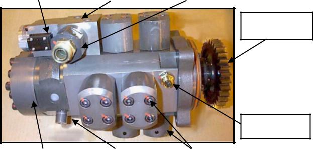
HIGH-PRESSURE FUEL PUMP
The high-pressure fuel pump is mounted on the front side of the gear case and is driven by the A-bank idler gear. The high-pressure pump utilizes a break away driven gear, which disengages itself in the event of a pump failure to prevent engine gear train damage.
HIGH-PRESSURE RAIL SUPPLY LINE, B-BANK
HIGH-PRESSURE PUMP CONTROL SOLENOID
HIGH-PRESSURE PUMP
HIGH-PRESSURE PUMP BODY FUEL RETURN LINE TO JUNCTION BLOCK
HIGH-PRESSURE RAIL SUPPLY LINE, A-BANK
HIGH-PRESSURE PUMPING UNITS
LOW-PRESSURE FUEL SUPPLY LINE
Fig. 15 High-pressure Fuel Pump Installation.
The high-pressure pump receives filtered low-pressure fuel from the fuel delivery pump at the control solenoid. The high-pressure pump control solenoid meters the amount of fuel entry to the high-pressure pump body and pumping units. The control solenoid is 24 volt operated to close against spring pressure in the open direction. (See Page 23).
Part of the fuel received by the high-pressure pump passes to the pump crankcase where it provides lubrication and cooling to the pump camshaft bearings and ceramic rings. The lubrication and cooling fuel exits the highpressure pump body by a fuel return line to the fuel junction block (See Fig. 15).
Page 17
HIGH-PRESSURE FUEL PUMP
24-VOLT POWER |
|
REGULATOR |
|
LOW-PRESSURE FUEL INLET |
SUPPLY CONNECTOR |
|
VALVE |
|
CHECK VALVE AND FILTER |
|
|
|
|
|
DRIVEN GEAR (BREAK AWAY)
FUEL RETURN
PORT
HIGH-PRESSURE |
|
HIGH-PRESSURE |
|
PUMPING UNITS |
ACCUMULATOR |
|
FUEL OUTLET |
|
|
|
Fig. 16 High-pressure Fuel Pump Assembly
The majority of the fuel entering the high-pressure pump is directed to high pressure pumping units for pressurization to the required operating pressure. There are eight pumping units shown in Figure 16, which are operated by the eccentric camshaft rings and controlled by inlet and outlet check valves. Fuel enters the pumping unit through the inlet check valve, pressurized by the piston to the high operating pressure, then exits through the outlet check valve to the accumulator. There are two high-pressure outlet ports for transferring the pressurized fuel to both the A-bank and B-bank high-pressure rails.
Page 18

HIGH-PRESSURE FUEL PUMP
CRANKCASE |
FUEL INLET |
|
SHAFT SEALS |
HIGH PRESSURE |
|
REGULATOR VALVE |
||
DRIVE GEAR |
||
COOLING AND |
||
ENGAGED |
||
|
LUBRICATING FUEL |
DRIVE GEAR |
HIGH PRESSURE ACCUMULATOR |
DISENGAGED |
|
CYLINDER |
CRANKSHAFT BEARING |
ECCENTRIC |
CERAMIC BEARINGS |
PISTON |
|
PISTON SPRING |
|
SIDE CUT AWAY VIEW (Fig. 17)
C Y LIN D ER
C R A NK C A S E
SUPPLY FUEL
CHECK VALVE INLE T
 HIGH PRESSURE FUEL
PISTON

 FOLLOW ER SPRING
 CHECK VALVE OUTLET
CENTER OF CAM
CENTER OF CRANK
CAMSHAFT (ECCENTRIC)
CERAMIC BEARING
END CUT AWAY VIEW (Fig. 18)
Page 19
Page 20
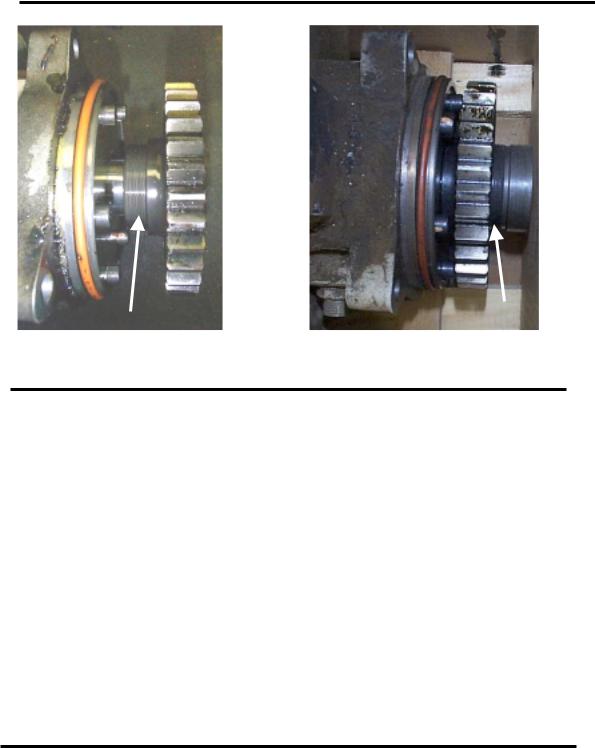
INSPECTION AND ANALYSIS
HIGH-PRESSURE FUEL PUMP
|
|
|
|
Fig. 19 Normal Gear Position |
Fig. 20 Disengaged Gear Position |
||
CONDITION: High-pressure pump seized, drive gear disengaged.
CAUSE: High-pressure fuel pump bearing failure. Low-pressure fuel flow restriction, which starved the high-pressure pump causing a lack of lubrication or cooling condition.
RECOMMENDATION: Replace High-pressure pump assembly and follow
fuel system cleaning procedure in Maintenance Section. Evaluate fuel system for source of low-pressure fuel flow restriction.
REUSE: Do Not Reuse!
NOTICE: Do not disassemble the high-pressure fuel pump for any reason! If the pump fails to rotate, replace the pump assembly. All highpressure fuel pumps are to be returned intact as Reliabilt® cores.
Page 21
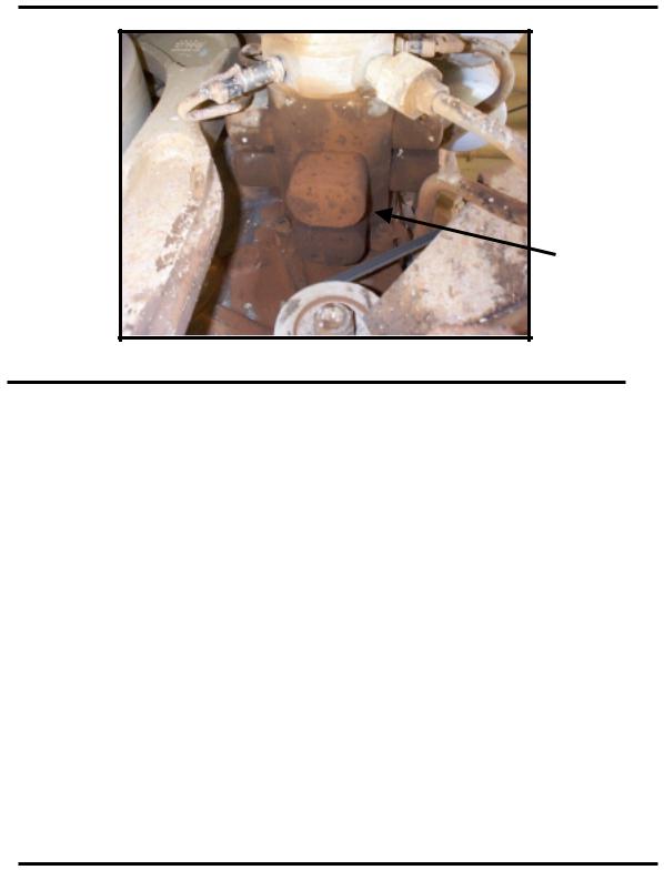
INSPECTION AND ANALYSIS
HIGH-PRESSURE FUEL PUMP
Fig. 21 High-pressure Fuel Pump Leak at Weep hole.
CONDITION: High-pressure pump leak at weep hole. A damp area at the pump weep hole is acceptable for service. Continuous dripping at the weep hole would define a leak and require servicing.
CAUTION: Presence of excessive amount of diesel fuel could present a safety hazard and should be addressed immediately.
CAUSE: Pump drive shaft pump body seal leaking. Fuel system contaminates can contribute to this cause. Excessive fuel temperature or dry operation of the pump may also result in seal damage.
RECOMMENDATION: Replace High-pressure pump assembly. Evaluate fuel condition and condition of equipment fuel system for contributing factors. Review events of dry operation and priming procedures being used.
REUSE: Do Not Reuse!
NOTICE: Do not disassemble the high-pressure fuel pump for any reason! All high-pressure fuel pumps are to be returned intact as Reliabilt® cores.
Page 22
Loading...