


SERIES 92 SERVICE MANUAL
Diesel engine exhaust and some of its constituents are known to the State of California to cause cancer, birth defects, and other reproductive harm.
Always start and operate an engine in a well ventilated area.
If operating an engine in an enclosed area, vent the exhaust to the outside.
Do not modify or tamper with the exhaust system or emission control system.
ABSTRACT
This manual provides instruction for servicing on-highway, industrial, generator set, and marine applications of the Detroit Diesel Series 92 Engines.
Specifically a basic overview of each major component and system along with recommendations for removal, cleaning, inspection, criteria for replacement, repair and installation and mechanical troubleshooting are contained in this manual.
DDEC® III/IV troubleshooting concerns are contained in the DDEC III/IV Single ECM Troubleshooting Guide, 6SE497.
3M Super Tack™ is a trademark of Minnesota Mining and Manufacturing Company. Aeroshell ® is a registered trademark of Shell Oil Company. Allison® is a registered trademark of General Motors Corporation. Alvania® is a registered trademark of Shell Oil Company. Barber-Colman®
is a registered trademark of Barber-Colman Company. Biobor® is a registered trademark of United States Borax and Chemical Corporation. Cindol® is a registered trademark of E.F. Houghton & Co. DDEC® is a registered trademark of Detroit Diesel Corporation. Delco Remy® is a registered trademark of Delco Remy America, Inc. Donaldson® is a registered trademark of Donaldson Company, Inc. Dow Corning® is a
registered trademark of Dow Corning Corporation. Endurion® is a registered trademark of Jason Incorporated. Fuel Pro® is a registered trademark of Davco Manufacturing, L.L.C. Jabsco® is a registered trademark of ITT Industries. Jake Brake® is a registered trademark of Diesel Engine Retarders, Inc. Kent-Moore® is a registered trademark of SPX Corporation. Leece-Neville® is a registered trademark of Leece-Neville Company. Loctite® is a registered trademark of Loctite Corporation. Lubriplate® is a registered trademark of Fiske Brothers Refining Company. Lubrite®
is a registered trademark of Henkel Corporation. Mobilgrease® is a registered trademark of Mobil Oil Corporation. Permatex® is a registered trademark of Loctite Corporation. Power Cool® is a registered trademark of Detroit Diesel Corporation. Power Trac® is a registered trademark of Detroit Diesel Corporation. Red-Jaket® is a registered trademark of INCOM International, Inc. reliabilt® is a registered trademark of Detroit Diesel Corporation. Rockford® is a registered trademark of Rockford Powertrain, Inc. Sea Pro® is a registered trademark of Davco Manufacturing, L.L.C. Shell® is a registered trademark of Shell Oil Corporation. Starrett® is a registered trademark of L.S. Starrett Company. STP® is a registered trademark of First Brand Corporation. Teflon® is a registered trademark of E.I. DuPont de Nemours and Company, Inc. Texaco® is a registered trademark of Texaco, Inc. Twin Disc® is a registered trademark of Twin Disc, Inc. Viton® is a registered trademark of Dupont Dow Elastomers L.L.C. Volvo® is a registered trademark of Volvo Trademark Holding AB. WD-40® is a registered trademark of WD-40 Company. Woodward® is a registered trademark of Woodward Governor Company.
All information subject to change without notice.
6SE379 0303 Copyright © 2003 DETROIT DIESEL CORPORATION |
i |
SERIES 92 SERVICE MANUAL
REVISION NOTIFICATION
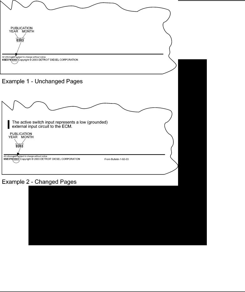
Modifications to this manual are announced in the form of Service Information Bulletins. The bulletins include attachment pages and are posted on the World Wide Web (www.detroitdiesel.com/svc/sibindex.htm).
Revisions to this manual will be sent marked with a revision bar (see Example 2). Sections containing revisions will have a third line in the page footer (compare Examples 1 and 2).
All information subject to change without notice.
ii |
6SE379 0303 Copyright © 2003 DETROIT DIESEL CORPORATION |

SERIES 92 SERVICE MANUAL
TABLE OF CONTENTS
|
GENERAL INFORMATION ...................................................................... |
1 |
|
SCOPE AND USE OF THIS MANUAL ..................................................... |
3 |
|
SAFETY PRECAUTIONS ........................................................................ |
3 |
|
FLUOROELASTOMER (VITON) CAUTION ............................................. |
10 |
|
SERVICE PARTS AVAILABILITY ............................................................. |
11 |
|
CLEARANCE AND TORQUE SPECIFICATIONS .................................... |
11 |
|
THE TWO CYCLE PRINCIPLE FOR DIESEL ENGINES ........................ |
12 |
|
GENERAL DESCRIPTION ..................................................................... |
13 |
|
DDEC DIAGNOSTIC READER CAUTION ............................................... |
15 |
|
DDEC I ..................................................................................................... |
16 |
|
DDEC II .................................................................................................... |
17 |
|
DDEC III .................................................................................................. |
17 |
|
GENERAL SPECIFICATIONS ................................................................ |
18 |
|
ENGINE MODEL, SERIAL NUMBER AND OPTION LABEL ................... |
21 |
|
REPAIR AND REPLACE .......................................................................... |
24 |
|
DISASSEMBLY ....................................................................................... |
25 |
|
CLEANING ............................................................................................... |
25 |
|
INSPECTION .......................................................................................... |
26 |
|
ASSEMBLY .............................................................................................. |
27 |
|
FABRICATING, ALTERING, REMOVING AND DISPOSING OF |
|
|
GASKETS ................................................................................................ |
27 |
|
ENGLISH TO METRIC CONVERSION .................................................... |
28 |
|
DECIMAL AND METRIC EQUIVALENTS ................................................ |
30 |
|
SPECIFICATIONS ................................................................................... |
30 |
1 |
ENGINE |
|
1.1 |
CYLINDER BLOCK ................................................................................. |
1-3 |
1.2 |
CYLINDER BLOCK END PLATES ........................................................... |
1-38 |
1.3 |
CYLINDER HEAD ................................................................................... |
1-47 |
1.4 |
VALVE AND INJECTOR OPERATING MECHANISM .............................. |
1-74 |
1.5 |
EXHAUST VALVES ................................................................................. |
1-102 |
1.6 |
VALVE ROCKER COVERS ...................................................................... |
1-126 |
1.7 |
CRANKSHAFT ........................................................................................ |
1-132 |
1.8 |
CRANKSHAFT OIL SEALS (FRONT AND REAR) .................................. |
1-166 |
1.9 |
CRANKSHAFT CAP ................................................................................ |
1-176 |
1.10 |
CRANKSHAFT MAIN BEARING SHELLS ............................................... |
1-180 |
1.11 |
ENGINE FRONT COVER ........................................................................ |
1-197 |
1.12 |
CRANKSHAFT OUTBOARD BEARING SUPPORT (TRUNNION) .......... |
1-202 |
1.13 |
CRANKSHAFT REAR OUTBOARD BEARING SUPPORT ..................... |
1-210 |
1.14 |
CRANKSHAFT VIBRATION DAMPER ..................................................... |
1-223 |
1.15 |
CRANKSHAFT PULLEY .......................................................................... |
1-238 |
1.16 |
FLYWHEEL ............................................................................................. |
1-243 |
All information subject to change without notice.
6SE379 0303 Copyright © 2003 DETROIT DIESEL CORPORATION |
iii |

SERIES 92 SERVICE MANUAL
1.17 |
CLUTCH PILOT BEARING ...................................................................... |
1-251 |
1.18 |
ENGINE DRIVE SHAFT FLEXIBLE COUPLING ..................................... |
1-256 |
1.19 |
FLYWHEEL HOUSING ............................................................................ |
1-264 |
1.20 |
PISTON AND PISTON RINGS ................................................................. |
1-284 |
1.21 |
CONNECTING ROD ................................................................................ |
1-308 |
1.22 |
CONNECTING ROD BEARINGS ............................................................. |
1-326 |
1.23 |
CYLINDER LINER .................................................................................. |
1-333 |
1.24 |
ENGINE BALANCE AND BALANCE WEIGHTS ..................................... |
1-347 |
1.25 |
GEAR TRAIN AND ENGINE TIMING ...................................................... |
1-348 |
1.26 |
CAMSHAFTS AND BEARINGS ............................................................... |
1-356 |
1.27 |
CAMSHAFT GEARS ............................................................................... |
1-385 |
1.28 |
IDLER GEAR AND BEARING ASSEMBLY .............................................. |
1-393 |
1.29 |
CRANKSHAFT TIMING GEAR ................................................................ |
1-416 |
1.30 |
BLOWER DRIVE GEAR AND SUPPORT ASSEMBLY ............................ |
1-427 |
1.31 |
ACCESSORY DRIVE ............................................................................... |
1-445 |
1.32 |
BALANCE WEIGHT COVER ................................................................... |
1-468 |
1.A |
ADDITIONAL INFORMATION .................................................................. |
1-473 |
2 |
FUEL SYSTEM |
|
2.1 |
FUEL SYSTEM ....................................................................................... |
2-3 |
2.2 |
MECHANICAL UNIT INJECTOR ............................................................. |
2-7 |
2.3 |
ELECTRONIC UNIT INJECTOR .............................................................. |
2-55 |
2.4 |
FUEL INJECTOR TUBE ........................................................................... |
2-66 |
2.5 |
ELECTRONIC ENGINE CONTROLS ...................................................... |
2-77 |
2.6 |
DDEC II .................................................................................................... |
2-83 |
2.7 |
DDEC III .................................................................................................. |
2-89 |
2.8 |
DDEC IV .................................................................................................. |
2-95 |
2.9 |
ELECTRONIC FOOT PEDAL ASSEMBLY ............................................... |
2-102 |
2.10 |
TURBO BOOST SENSOR ...................................................................... |
2-103 |
2.11 |
OIL PRESSURE SENSOR ..................................................................... |
2-106 |
2.12 |
OIL TEMPERATURE SENSOR ............................................................... |
2-109 |
2.13 |
PULSE WHEEL DDEC III AND II (6V AND 8V ENGINES) ...................... |
2-112 |
2.14 |
SYNCHRONOUS REFERENCE SENSOR (6V AND 8V) ........................ |
2-119 |
2.15 |
TIMING REFERENCE SENSOR ............................................................. |
2-123 |
2.16 |
COOLANT LEVEL SENSOR ................................................................... |
2-135 |
2.17 |
COOLANT TEMPERATURE SENSOR .................................................... |
2-141 |
2.18 |
COOLANT PRESSURE SENSOR (12V AND 16V) ................................. |
2-143 |
2.19 |
FUEL PRESSURE SENSOR ................................................................... |
2-145 |
2.20 |
FUEL TEMPERATURE SENSOR ............................................................ |
2-148 |
2.21 |
FUEL PUMP ............................................................................................ |
2-151 |
2.22 |
FUEL STRAINER AND FUEL FILTER ..................................................... |
2-176 |
2.23 |
FUEL COOLER ....................................................................................... |
2-184 |
2.24 |
LIMITING SPEED MECHANICAL GOVERNOR ...................................... |
2-187 |
2.25LIMITING SPEED MECHANICAL GOVERNOR (VARIABLE
LOW-SPEED) ........................................................................................... |
2-252 |
2.26LIMITING SPEED MECHANICAL GOVERNOR (VARIABLE HIGH
SPEED) .................................................................................................... |
2-266 |
All information subject to change without notice.
iv |
6SE379 0303 Copyright © 2003 DETROIT DIESEL CORPORATION |

|
SERIES 92 SERVICE MANUAL |
|
|
|
|
2.27 |
VARIABLE SPEED MECHANICAL GOVERNOR .................................... |
2-275 |
2.28 |
SG HYDRAULIC GOVERNORS .............................................................. |
2-328 |
2.29 |
PSG HYDRAULIC GOVERNOR .............................................................. |
2-367 |
2.30 |
HYDRAULIC GOVERNOR DRIVE ........................................................... |
2-376 |
2.31 |
HYDRAULIC GOVERNOR SYNCHRONIZING MOTOR .......................... |
2-413 |
2.32 |
ELECTRONIC GOVERNOR .................................................................... |
2-416 |
2.33 |
FUEL INJECTOR CONTROL TUBE (NON-DDEC ENGINES) ................ |
2-417 |
2.A |
ADDITIONAL INFORMATION .................................................................. |
2-431 |
3 |
LUBRICATING SYSTEM |
|
3.1 |
LUBRICATION SYSTEM .......................................................................... |
3-3 |
3.2 |
LUBRICATING OIL PUMP (6V AND 8V ENGINES) ................................ |
3-11 |
3.3 |
LUBRICATING OIL PUMP (12V AND 16V ENGINES) ............................ |
3-35 |
3.4 |
LUBRICATING OIL PRESSURE REGULATOR VALVE ........................... |
3-49 |
3.5 |
LUBRICATING OIL PRESSURE RELIEF VALVE .................................... |
3-58 |
3.6 |
LUBRICATING OIL FILTERS ................................................................... |
3-67 |
3.7 |
LUBRICATING OIL COOLER (PLATE TYPE) .......................................... |
3-79 |
3.8 |
LUBRICATING OIL COOLER (TUBE TYPE) ........................................... |
3-93 |
3.9 |
LUBRICATING OIL COOLER BYPASS VALVE ........................................ |
3-112 |
3.10 |
OIL LEVEL DIPSTICK .............................................................................. |
3-117 |
3.11 |
OIL PAN ................................................................................................... |
3-120 |
3.12 |
VENTILATING SYSTEM .......................................................................... |
3-126 |
3.A |
ADDITIONAL INFORMATION .................................................................. |
3-131 |
4 |
COOLING SYSTEM |
|
4.1 |
COOLING SYSTEM ................................................................................ |
4-3 |
4.2 |
WATER PUMP (6V AND 8V ENGINES) .................................................. |
4-5 |
4.3 |
WATER PUMP (12V AND 16V ENGINES) .............................................. |
4-23 |
4.4 |
WATER MANIFOLD ................................................................................ |
4-35 |
4.5 |
THERMOSTAT ........................................................................................ |
4-40 |
4.6 |
RADIATOR .............................................................................................. |
4-50 |
4.7 |
COOLANT PRESSURE CONTROL CAP ................................................ |
4-63 |
4.8 |
ENGINE COOLING FAN .......................................................................... |
4-66 |
4.9 |
HEAT EXCHANGER ............................................................................... |
4-94 |
4.10 |
RAW WATER PUMP ................................................................................ |
4-102 |
4.11 |
COOLANT FILTER AND CONDITIONER ................................................ |
4-116 |
4.A |
ADDITIONAL INFORMATION .................................................................. |
4-123 |
5 |
FUEL, LUBRICATING OIL, AND COOLANT |
|
5.1 |
FUEL ........................................................................................................ |
5-3 |
5.2 |
LUBRICATING OIL REQUIREMENTS ..................................................... |
5-19 |
5.3 |
COOLANT ................................................................................................ |
5-28 |
6 |
AIR INTAKE SYSTEM |
|
6.1 |
AIR INTAKE SYSTEM ............................................................................. |
6-3 |
6.2 |
AIR CLEANER ........................................................................................ |
6-5 |
6.3 |
AIR SEPARATOR FILTER ELEMENT ...................................................... |
6-13 |
6.4 |
AIR SHUTDOWN HOUSING ................................................................... |
6-15 |
6.5 |
BLOWER .................................................................................................. |
6-27 |
All information subject to change without notice.
6SE379 0303 Copyright © 2003 DETROIT DIESEL CORPORATION |
v |

SERIES 92 SERVICE MANUAL
6.6 |
TURBOCHARGER (AIRESEARCH) ........................................................ |
6-89 |
6.7 |
TURBOCHARGER INTERCOOLER ........................................................ |
6-120 |
6.8 |
TURBOCHARGER AFTERCOOLER ....................................................... |
6-128 |
6.A |
ADDITIONAL INFORMATION .................................................................. |
6-139 |
7 |
EXHAUST SYSTEM |
|
7.1 |
EXHAUST SYSTEM ................................................................................ |
7-3 |
7.2 |
EXHAUST MANIFOLD ............................................................................ |
7-5 |
7.3 |
EXHAUST MANIFOLD (WATER-COOLED) ............................................. |
7-11 |
8 |
ELECTRICAL EQUIPMENT |
|
8.1 |
BATTERY-CHARGING ALTERNATOR .................................................... |
8-3 |
8.2 |
STARTING MOTOR ................................................................................. |
8-12 |
8.3 |
TACHOMETER DRIVE ............................................................................. |
8-15 |
8.4 |
INSTRUMENTS ...................................................................................... |
8-20 |
8.5 |
ENGINE PROTECTIVE SYSTEMS ......................................................... |
8-24 |
8.6 |
ALARM SYSTEM .................................................................................... |
8-45 |
8.7 |
OVERSPEED GOVERNOR ..................................................................... |
8-52 |
8.A |
ADDITIONAL INFORMATION .................................................................. |
8-59 |
9 |
POWER TAKE-OFF |
|
9.1 |
POWER TAKE-OFF TORQMATIC CONVERTER .................................... |
9-3 |
10 |
SPECIAL EQUIPMENT |
|
10.1 |
AIR COMPRESSOR ............................................................................... |
10-3 |
10.2 |
ENGINE BLOCK HEATER ....................................................................... |
10-9 |
10.3 |
TRANSMISSIONS .................................................................................. |
10-10 |
11 |
OPERATION AND VERIFICATION |
|
11.1 |
PREPARATION FOR A FIRST TIME START ........................................... |
11-3 |
11.2 |
STARTING ............................................................................................... |
11-8 |
11.3 |
RUNNING ................................................................................................. |
11-11 |
11.4 |
STOPPING .............................................................................................. |
11-16 |
11.5 |
OPERATING CONDITIONS ..................................................................... |
11-18 |
11.6 |
ENGINE RUN-IN PROCEDURES ............................................................ |
11-52 |
12 |
ENGINE TUNE-UP |
|
12.1 |
ENGINE TUNE-UP ................................................................................. |
12-3 |
12.2 |
EXHAUST VALVE CLEARANCE ADJUSTMENT .................................... |
12-28 |
12.3 |
FUEL INJECTOR TIMING ........................................................................ |
12-32 |
12.4LIMITING SPEED MECHANICAL GOVERNOR INJECTOR RACK
CONTROL ADJUSTMENT (6V AND 8V ENGINES) ............................... |
12-35 |
12.5LIMITING SPEED MECHANICAL GOVERNOR AND INJECTOR RACK
CONTROL ADJUSTMENT (12V AND 16V ENGINES) ............................ |
12-86 |
12.6STATIC DOUBLE WEIGHT LIMITING SPEED GOVERNOR GAP
CHECKING AND SETTING PROCEDURE ............................................. |
12-118 |
12.7LIMITING SPEED MECHANICAL GOVERNOR ADJUSTMENT
|
(VARIABLE LOW-SPEED) ....................................................................... |
12-129 |
12.8 |
LIMITING SPEED MECHANICAL GOVERNOR FAST IDLE CYLINDER |
12-139 |
12.9 |
GOVERNOR SETTINGS FOR "TT" ENGINES ........................................ |
12-143 |
All information subject to change without notice.
vi |
6SE379 0303 Copyright © 2003 DETROIT DIESEL CORPORATION |

|
SERIES 92 SERVICE MANUAL |
|
|
|
|
12.10 |
VARIABLE SPEED MECHANICAL GOVERNOR INJECTOR RACK |
|
|
CONTROL ADJUSTMENT (6V AND 8V ENGINES) ............................... |
12-173 |
12.11 |
VARIABLE SPEED MECHANICAL GOVERNOR AND INJECTOR RACK |
|
|
CONTROL ADJUSTMENT (12V AND 16V ENGINES) ............................ |
12-186 |
12.12 |
SG VARIABLE SPEED HYDRAULIC GOVERNOR INJECTOR RACK |
|
|
CONTROL ADJUSTMENT (6V AND 8V ENGINES) ............................... |
12-204 |
12.13 |
SG VARIABLE SPEED HYDRAULIC GOVERNOR INJECTOR RACK |
|
|
CONTROL ADJUSTMENT (12V AND 16V) ............................................. |
12-223 |
12.14 |
GOVERNORS WITH SYNCHRONIZING MOTOR ................................... |
12-243 |
12.15 |
SUPPLEMENTARY GOVERNING DEVICE ADJUSTMENT .................... |
12-244 |
12.16 |
POWER CONTROL DEVICE ................................................................... |
12-248 |
12.17 |
THROTTLE DELAY MECHANISM ADJUSTMENT .................................. |
12-251 |
12.18 |
FUEL MODULATOR ................................................................................ |
12-264 |
13 |
PREVENTIVE MAINTENANCE |
|
13.1 |
PREVENTIVE MAINTENANCE ITEMS DESCRIPTION .......................... |
13-5 |
13.2 |
MAINTENANCE OF VEHICLE ENGINE .................................................. |
13-6 |
13.3 |
MAINTENANCE OF STATIONARY AND INDUSTRIAL ENGINE ............ |
13-12 |
13.4 |
MAINTENANCE OF PLEASURE CRAFT MARINE ENGINES ................ |
13-16 |
13.5 |
LUBRICATING OIL ................................................................................... |
13-19 |
13.6 |
OIL PRESSURE ...................................................................................... |
13-26 |
13.7 |
LUBRICATING OIL FILTER ...................................................................... |
13-27 |
13.8 |
FUEL STRAINER AND FILTER ............................................................... |
13-29 |
13.9 |
FUEL TANK ............................................................................................. |
13-32 |
13.10 |
FUEL CONTAMINATION .......................................................................... |
13-33 |
13.11 |
FUEL LINES AND FLEXIBLE HOSES ..................................................... |
13-34 |
13.12 |
COOLING SYSTEM ................................................................................ |
13-36 |
13.13 |
WATER PUMP ........................................................................................ |
13-49 |
13.14 |
COOLANT FILTER .................................................................................. |
13-50 |
13.15 |
COOLANT FILTER/INHIBITOR PRECHARGE ELEMENT ...................... |
13-51 |
13.16 |
RADIATOR .............................................................................................. |
13-53 |
13.17 |
TURBOCHARGER AND EXHAUST CONNECTIONS ............................. |
13-54 |
13.18 |
DRIVE BELTS ......................................................................................... |
13-58 |
13.19 |
BATTERY ................................................................................................. |
13-65 |
13.20 |
BATTERY CHARGING ALTERNATOR ..................................................... |
13-68 |
13.21 |
ENGINE AND TRANSMISSION MOUNTS .............................................. |
13-70 |
13.22 |
ENGINE TUNE-UP ................................................................................. |
13-71 |
13.23 |
BLOWER BYPASS VALVE ....................................................................... |
13-72 |
13.24 |
TACHOMETER DRIVE ............................................................................. |
13-73 |
13.25 |
AIR COMPRESSOR ............................................................................... |
13-74 |
13.26 |
THROTTLE AND CLUTCH CONTROLS ................................................. |
13-75 |
13.27 |
AIR BOX DRAIN TUBE ............................................................................ |
13-76 |
13.28 |
AIR BOX CHECK VALVES ....................................................................... |
13-77 |
13.29 |
SHUTTER OPERATION ......................................................................... |
13-78 |
13.30 |
GOVERNOR, OVERSPEED GOVERNOR .............................................. |
13-79 |
13.31 |
THROTTLE DELAY FUEL MODULATOR ................................................ |
13-80 |
13.32 |
FAN HUB .................................................................................................. |
13-81 |
All information subject to change without notice.
6SE379 0303 Copyright © 2003 DETROIT DIESEL CORPORATION |
vii |

SERIES 92 SERVICE MANUAL
13.33 |
FAN (THERMO-MOUNTED) ................................................................... |
13-83 |
13.34 |
THERMOSTATS AND SEALS .................................................................. |
13-84 |
13.35 |
BLOWER SCREEN ................................................................................. |
13-85 |
13.36 |
FUEL INJECTORS AND VALVE CLEARANCE ....................................... |
13-87 |
13.37 |
VIBRATION DAMPER .............................................................................. |
13-88 |
13.38 |
STARTING MOTOR ................................................................................. |
13-89 |
13.39 |
EXHAUST SYSTEM ................................................................................ |
13-91 |
13.40 |
CRANKCASE BREATHER (EXTERNALLY MOUNTED) ......................... |
13-92 |
13.41 |
CRANKCASE BREATHER (INTERNALLY MOUNTED) .......................... |
13-93 |
13.42 |
ENGINE (STEAM CLEAN) ....................................................................... |
13-94 |
13.43 |
POWER TAKE-OFF ................................................................................ |
13-95 |
13.44 |
TORQMATIC CONVERTER ..................................................................... |
13-97 |
13.45 |
REDUCTION GEAR ................................................................................. |
13-99 |
13.46 |
TRANSIT COACH CONVERTER MUFFLER ........................................... |
13-101 |
13.47 |
AIR CLEANER ........................................................................................ |
13-103 |
13.48 |
AIR SYSTEM .......................................................................................... |
13-106 |
13.49 |
AIR SEPARATOR FILTER ELEMENT ...................................................... |
13-107 |
13.50 |
AIR SHUTDOWN VALVE ......................................................................... |
13-111 |
13.51 |
COOLING SYSTEM (MARINE) ............................................................... |
13-112 |
13.52 |
HEAT EXCHANGER CHANGEOUT INTERVAL ...................................... |
13-113 |
13.53 |
HEAT EXCHANGER ELECTRODES AND CORE (RAW WATER |
|
|
SYSTEM ZINCS) ..................................................................................... |
13-116 |
13.54 |
RAW WATER PUMP ................................................................................ |
13-118 |
13.55 |
FUEL AND BOOST COOLERS ............................................................... |
13-121 |
13.56 |
TORQMATIC MARINE GEAR (6V AND 8V) ............................................ |
13-122 |
13.57 |
MARINE GEAR (TWIN DISC 16V) .......................................................... |
13-124 |
13.58 |
CLUTCH ACTUATOR (DDEC MARINE) .................................................. |
13-126 |
14 |
STORAGE |
|
14.1 |
PREPARING ENGINE FOR STORAGE ................................................... |
14-3 |
14.2 |
TEMPORARY ENGINE STORAGE (30 DAYS OR LESS) ....................... |
14-4 |
14.3RESTORING A TEMPORARILY STORED ENGINE (30 DAYS OR
LESS) ....................................................................................................... |
14-6 |
14.4 EXTENDED ENGINE STORAGE (MORE THAN 30 DAYS) .................... |
14-7 |
14.5RESTORING AN EXTENDED STORAGE ENGINE (MORE THAN 30
DAYS) ....................................................................................................... |
14-13 |
14.6 STORAGE OF BATTERY ......................................................................... |
14-16 |
INDEX ................................................................................................. |
Index-1 |
All information subject to change without notice.
viii |
6SE379 0303 Copyright © 2003 DETROIT DIESEL CORPORATION |
SERIES 92 SERVICE MANUAL
ENGINE EXHAUST
Consider the following before servicing engines:
Diesel engine exhaust and some of its constituents are known to the State of California to cause cancer, birth defects, and other reproductive harm.
Always start and operate an engine in a well ventilated area.
If operating an engine in an enclosed area, vent the exhaust to the outside.
Do not modify or tamper with the exhaust system or emission control system.
Please note this caution and remember:
Always start and operate the engine in a well ventilated area. If in an enclosed area, vent the exhaust to the outside.
Do not modify or tamper with the exhaust system.For accurate dynamometer readings during a engine run-in, the chassis dynamometer room must be properly ventilated.
Diesel engine exhaust and some of its constituents are known to the State of California to cause cancer, birth defects, and other reproductive harm.
Always start and operate an engine in a well ventilated area.
If operating an engine in an enclosed area, vent the exhaust to the outside.
Do not modify or tamper with the exhaust system or emission control system.
All information subject to change without notice.
6SE379 0303 Copyright © 2003 DETROIT DIESEL CORPORATION |
ix |

SERIES 92 SERVICE MANUAL
All information subject to change without notice.
x |
6SE379 0303 Copyright © 2003 DETROIT DIESEL CORPORATION |

GENERAL INFORMATION
Section |
Page |
SCOPE AND USE OF THIS MANUAL ....................................................... |
3 |
SAFETY PRECAUTIONS ........................................................................... |
3 |
FLUOROELASTOMER (VITON) CAUTION ................................................ |
10 |
SERVICE PARTS AVAILABILITY ................................................................ |
11 |
CLEARANCE AND TORQUE SPECIFICATIONS ....................................... |
11 |
THE TWO CYCLE PRINCIPLE FOR DIESEL ENGINES ........................... |
12 |
GENERAL DESCRIPTION ........................................................................ |
13 |
DDEC DIAGNOSTIC READER CAUTION .................................................. |
15 |
DDEC I ........................................................................................................ |
16 |
DDEC II ....................................................................................................... |
17 |
DDEC III ..................................................................................................... |
17 |
GENERAL SPECIFICATIONS ................................................................... |
18 |
ENGINE MODEL, SERIAL NUMBER AND OPTION LABEL ..................... |
21 |
REPAIR AND REPLACE ............................................................................. |
24 |
DISASSEMBLY .......................................................................................... |
25 |
CLEANING .................................................................................................. |
25 |
INSPECTION ............................................................................................. |
26 |
ASSEMBLY ................................................................................................. |
27 |
FABRICATING, ALTERING, REMOVING AND DISPOSING OF |
|
GASKETS ............................................................................................ |
27 |
ENGLISH TO METRIC CONVERSION ...................................................... |
28 |

SERIES 92 SERVICE MANUAL |
|
DECIMAL AND METRIC EQUIVALENTS ................................................... |
30 |
SPECIFICATIONS ..................................................................................... |
30 |
All information subject to change without notice.
2 |
6SE379 0303 Copyright © 2003 DETROIT DIESEL CORPORATION |

SERIES 92 SERVICE MANUAL
SCOPE AND USE OF THIS MANUAL
This manual covers the basic V-92 diesel engines built by the Detroit Diesel Corporation. Complete instructions on operation, adjustment (tune-up), preventive maintenance, and lubrication and repair (including complete overhaul) are covered. Basic maintenance and overhaul procedures are common to all V-92 engines and apply to all engine models.
The manual is divided into numbered sections. The first section covers the engine (less major assemblies). The following sections cover a complete system such as the fuel system, lubrication system or air system. Each section is divided into subsections containing complete maintenance and operating instructions for a specific subassembly on the engine. Each section begins with a table of contents. Pages and illustrations are numbered consecutively within each section.
Information can be located using the table of contents at the front of the manual or the table of contents at the beginning of each section. Information on specific subassemblies within the major section is listed immediately following the section title.
SAFETY PRECAUTIONS
The following safety measures are essential when working on the Series 92 engine.
Please note this caution and remember:
Always start and operate the engine in a well ventilated area.
If in an enclosed area, vent the exhaust outside.
Do not modify or tamper with the exhaust system.
Diesel engine exhaust and some of its constituents are known to the State of California to cause cancer, birth defects, and other reproductive harm.
Always start and operate an engine in a well ventilated area.
If operating an engine in an enclosed area, vent the exhaust to the outside.
Do not modify or tamper with the exhaust system or emission control system.
Stands
Safety stands are required in conjunction with hydraulic jacks or hoists. Do not rely on either the jack or the hoist to carry the load. When lifting an engine, ensure lifting device is fastened securely. Ensure that the item to be lifted does not exceed the capacity of the lifting device.
Glasses
Select appropriate safety glasses for the job. It is especially important to wear safety glasses when using tools such as hammers, chisels, pullers, or punches.
All information subject to change without notice.
6SE379 0303 Copyright © 2003 DETROIT DIESEL CORPORATION |
3 |

SERIES 92 SERVICE MANUAL
Welding
Wear welding goggles and gloves when welding or using an acetylene torch. Ensure that a metal shield separates the acetylene and oxygen that must be chained to a cart.
All information subject to change without notice.
4 |
6SE379 0303 Copyright © 2003 DETROIT DIESEL CORPORATION |
SERIES 92 SERVICE MANUAL
To avoid injury from arc welding, gas welding, or cutting, wear required safety equipment such as an arc welder’s face plate or gas welder’s goggles, welding gloves, protective apron, long sleeve shirt, head protection, and safety shoes. Always perform welding or cutting operations in a well-ventilated area. The gas in oxygen/acetylene cylinders used in gas welding and cutting is under high pressure. If a cylinder should fall due to careless handling, the gage end could strike an obstruction and fracture, resulting in a gas leak leading to fire or an explosion. If a cylinder should fall resulting in the gage end breaking off, the sudden release of cylinder pressure will turn the cylinder into a dangerous projectile. Observe the following precautions when using oxygen/acetylene gas cylinders:
Always wear required safety shoes.
Do not handle tanks in a careless manner or with greasy gloves or slippery hands.
Use a chain, bracket, or other restraining device at all times to prevent gas cylinders from falling.
Do not place gas cylinders on their sides, but stand them upright when in use.
Do not drop, drag, roll, or strike a cylinder forcefully. Always close valves completely when finished welding or cutting.
To avoid injury from fire, keep all potential ignition sources away from diesel fuel, open flames, sparks, and electrical resistance heating elements. Do not smoke when refueling.
Work Place
Organize your work area, and keep it clean. A fall could result in a serious injury. Eliminate the possibility of a fall by:
Wiping up oil spills.
Keeping tools and parts off the floor.
After servicing or adjusting the engine:
Install all safety devices, guards, or shields.
Ensure that all tools and service equipment are removed from the engine.
All information subject to change without notice.
6SE379 0303 Copyright © 2003 DETROIT DIESEL CORPORATION |
5 |
SERIES 92 SERVICE MANUAL
Clothing
Wear safe work clothes that fit and are in good condition. Work shoes are sturdy and rough-soled. Bare feet, sandals, or sneakers are not acceptable foot wear when adjusting and/or servicing an engine. Do not wear the following when working on an engine:
To avoid injury when working near or on an operating engine equipped with electric fans, remove loose items of clothing, jewelry; tie back or contain long hair that could be caught in any moving part causing injury. Electric fans may start without warning.
Rings
Wrist watches
Loose fitting clothing
Any of these items could catch on moving parts causing serious injury.
Power Tools
Do not use defective portable power tools. Check for frayed cords prior to using the tool. Ensure that all electric tools are grounded. Defective electrical equipment and improper use of electrical equipment can cause severe injury.
To avoid injury from electrical shock, follow OEM furnished operating instructions prior to usage.
Air
Recommendations regarding the use of compressed air are indicated throughout the manual with the following:
All information subject to change without notice.
6 |
6SE379 0303 Copyright © 2003 DETROIT DIESEL CORPORATION |

SERIES 92 SERVICE MANUAL
To avoid injury from flying debris when using compressed air, wear adequate eye protection (face shield or safety goggles) and do not exceed 40 psi (276 kPa) air pressure.
Too much air can rupture or in some other way damage a component and create a hazardous situation that can lead to personal injury. Use only approved air blow guns that do not exceed 276 kPa (40 lb/in.2). Wear safety glasses or goggles. Use proper shielding to protect everyone in the work area.
Fluids and Pressure
Be extremely careful when dealing with fluids under pressure.
To avoid injury from penetrating fluids, do not put your hands in front of fluid under pressure. Fluids under pressure can penetrate skin and clothing.
Fluids under pressure can penetrate the skin. These fluids can infect a minor cut or opening in the skin. If injured, see a doctor immediately.
Fuel
Keep the hose and nozzle or the funnel and container in contact with the metal of the fuel tank when refueling to avoid the possibility of an electric spark igniting the fuel.
The following cautions should be followed when filling a fuel tank:
All information subject to change without notice.
6SE379 0303 Copyright © 2003 DETROIT DIESEL CORPORATION |
7 |
SERIES 92 SERVICE MANUAL
To avoid injury from fire, do not overfill the fuel tank.
To avoid injury from fire, keep all potential ignition sources away from diesel fuel, open flames, sparks, and electrical resistance heating elements. Do not smoke when refueling.
To avoid injury from fire, keep all potential ignition sources away from diesel fuel, open flames, sparks, and electrical resistance heating elements. Do not smoke when refueling.
Batteries
Electrical storage batteries emit highly flammable hydrogen gas when charging and continue to do so for some time after receiving a steady charge.
To avoid injury from battery explosion or contact with battery acid, work in a well-ventilated area, wear protective clothing, and avoid sparks or flames near the battery. Always establish correct polarity before connecting cables to the battery or battery circuit. If you come in contact with battery acid:
Flush your skin with water.
Apply baking soda or lime to help neutralize the acid.
Flush your eyes with water.
Get medical attention immediately.
Always disconnect the battery cable before working on the electrical system.
All information subject to change without notice.
8 |
6SE379 0303 Copyright © 2003 DETROIT DIESEL CORPORATION |
SERIES 92 SERVICE MANUAL
To avoid injury from accidental engine startup while servicing the engine, disconnect/disable the starting system.
Disconnect the batteries or disable an air starter when working on the engine to prevent accidental starting.
Fire
Keep a charged fire extinguisher within reach. Ensure the correct type of extinguisher is used for the situation.
Cleaning Agent
Avoid the use of carbon tetrachloride as a cleaning agent because of the harmful vapors that it releases. Ensure work area is adequately ventilated. Use protective gloves, goggles or face shield, and apron.
Working on a Running Engine
When working on a running engine, accidental contact with the hot exhaust manifold can cause severe burns. Remain alert to the location of the rotating fan, pulleys and belts. Avoid making contact across the two terminals of a battery which can result in severe arcing, or battery explosion.
To avoid injury from hot surfaces, allow engine to cool before removing any component. Wear protective gloves.
To avoid injury, use care when working around moving belts and rotating parts on the engine.
Start Attempts
Observe the following caution when working with mineral spirits or mineral spirit-based solvents.
All information subject to change without notice.
6SE379 0303 Copyright © 2003 DETROIT DIESEL CORPORATION |
9 |

SERIES 92 SERVICE MANUAL
To avoid injury from flames, explosion, and toxicants when using ether, the following precautions must be taken:
Do not smoke when servicing ether system.
Work in well-ventilated area.
Do not work near open flames, pilot flames (gas or oil heaters), or sparks.
Do not weld or carry an open flame near the ether system if you smell ether or otherwise suspect a leak.
Always wear goggles when testing.
If fluid enters the eyes or if fumes irritate the eyes, wash eyes with large quantities of clean water for 15 minutes. A physician, preferably an eye specialist, should be contacted.
Contents of cylinder are under pressure. Store cylinders in a cool dry area. Do not incinerate, puncture or attempt to remove cores from cylinders.
Avoid excessive injection of ether into the engine during start attempts. Follow the instructions on the container or by the manufacturer of the starting aid.
FLUOROELASTOMER (VITON) CAUTION
Observe the following caution when handling fluoroelastomer.
All information subject to change without notice.
10 |
6SE379 0303 Copyright © 2003 DETROIT DIESEL CORPORATION |

SERIES 92 SERVICE MANUAL
To avoid injury from chemical burns, wear a face shield and neoprene or PVC gloves when handling fluoroelastomer O-rings or seals that have been degraded by excessive heat. Discard gloves after handling degraded fluoroelastomer parts.
Under normal design conditions, fluoroelastomer (Viton® ) parts, such as O-rings and seals, are perfectly safe to handle. They may become hazardous, however, if these components are subjected to temperatures above 316 C (600
 F), such as during a cylinder failure or engine fire. At temperatures above 316
 C (600
 F), fluoroelastomer will decompose (indicated by charring or the appearance of a black, sticky mass) and produce hydrofluoric acid. This is extremely corrosive and, if it contacts bare skin, it may cause severe burns, sometimes with symptoms delayed for several hours.
SERVICE PARTS AVAILABILITY
Genuine Detroit Diesel service parts are available from authorized Detroit Diesel distributors and service dealers throughout the world. A complete list of all distributors and dealers is available in the World Wide Parts and Service Directory, 6SE280. This publication can be ordered from any authorized distributor.
CLEARANCE AND TORQUE SPECIFICATIONS
Refer to section ADDITIONAL INFORMATION for a listing of new part clearances and used part wear limits. The appropriate use of information from the limits column requires service personnel to exercise good judgment. The wear limits recorded, in general, apply only to those parts most frequently replaced during engine overhaul. For additional information, refer to repair or replace in this chapter.
All information subject to change without notice.
6SE379 0303 Copyright © 2003 DETROIT DIESEL CORPORATION |
11 |

SERIES 92 SERVICE MANUAL
THE TWO CYCLE PRINCIPLE FOR DIESEL ENGINES
In the two-cycle engine, intake and exhaust take place during part of the compression and power strokes respectively. See Figure 1.
Figure 1 The Two-Stroke Cylinder Engine
Scavenging
A blower forces air into the cylinders to expel the exhaust gases and to supply the cylinders with fresh air for combustion. The cylinder wall contains a row of ports which are above the piston when it is at the bottom of its stroke. These ports admit air from the blower into the cylinder as soon as the rim of the piston uncovers the ports.
The unidirectional air flow toward the exhaust valves produces a scavenging effect, leaving the cylinders full of clean air when the piston again covers the inlet ports.
All information subject to change without notice.
12 |
6SE379 0303 Copyright © 2003 DETROIT DIESEL CORPORATION |

SERIES 92 SERVICE MANUAL
Compression
As the piston continues on the upward stroke, the exhaust valves close, and the charge of fresh air is compressed.
Power
Shortly before the piston reaches its highest position, the unit fuel injector sprays the required amount of fuel into the combustion chamber. The intense heat generated during the high air compression immediately ignites the fine fuel spray. The combustion continues until the injected fuel has been burned.
Exhaust
The resulting pressure forces the piston downward on its power stroke. The exhaust valves are again opened when the piston is about half way down, allowing the burned gases to escape into the exhaust manifold. Shortly thereafter, the downward moving piston uncovers the inlet ports and the cylinder is once again swept with clean scavenging air. This entire combustion cycle is completed in each cylinder for each crankshaft revolution, in other words, in two strokes. Hence, it is a "two-stroke cycle".
GENERAL DESCRIPTION
The two-cycle diesel engines covered in this manual are produced in 6, 8, 12, and 16 cylinder models. Each model shares the same bore and stroke and many of the major working parts such as injectors, pistons, connecting rods, cylinder liners and other interchangeable parts.
All information subject to change without notice.
6SE379 0303 Copyright © 2003 DETROIT DIESEL CORPORATION |
13 |
SERIES 92 SERVICE MANUAL
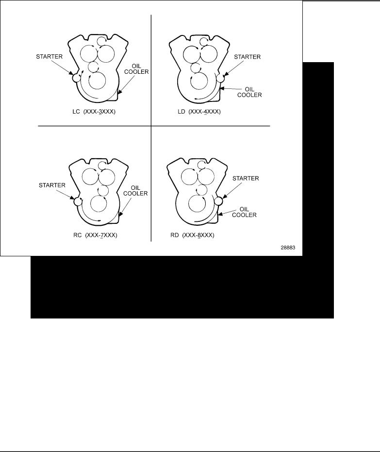
The engines are built with right-hand or left-hand crankshaft rotation. See Figure 2. The oil cooler can be mounted only on the right side of the engine. On 6V and 8V engines the starter can be mounted on either the right or left side of the engine, and the 12V and 16V engines have a starter on both the right and left side of the engine.
Figure 2 Views From Rear of Engine
See Figure 2 for the meaning of each digit in the model numbering system. The letter L or R indicates left or right-hand engine rotation as viewed from the front of the engine. The letter A, B, C, or D designates the location of the starter and oil cooler as viewed from the rear of the engine.
Each engine is equipped with oil coolers, lubricating oil filters, fuel oil strainer, fuel oil filter, air cleaners, governor, heat exchanger and raw water pump or fan and radiator, and starting motor.
All information subject to change without notice.
14 |
6SE379 0303 Copyright © 2003 DETROIT DIESEL CORPORATION |

SERIES 92 SERVICE MANUAL
Full pressure lubrication is supplied to all main, connecting rod and camshaft bearings, and to other moving parts within the engine. A gear-type pump draws oil from the oil pan through an intake screen, through the oil filter, and then to the oil cooler. From the oil cooler, the oil flows through passages that connect with the oil galleries in the cylinder block and cylinder heads for distribution to the bearings, rocker arm mechanism and other functional parts.
Coolant is circulated through the engine by a centrifugal-type water pump. Heat is removed from the coolant, which circulates in a closed system, by the radiator or heat exchanger. Engine temperature is controlled by thermostats that regulate the flow of the coolant within the cooling system.
Fuel is drawn from the supply tank through the fuel filter by a gear-type fuel pump. It is then forced through a filter and into the fuel inlet manifolds in the cylinder heads and to the injectors. Excess fuel is returned to the supply tank through the fuel outlet manifolds and connecting lines. Since the fuel is constantly circulating through the injectors, it serves to cool the injectors and also carries off any air in the fuel system.
A blower that pumps air into the engine cylinders via the air box and cylinder liner ports supplies air for scavenging and combustion. All air entering the blower passes through an air cleaner.
An electric starting system starts the engine. A storage battery energizes the electric starting motor. A battery-charging generator, with a suitable voltage regulator or an alternator keeps the battery charged.
Engine speed is regulated by a mechanical or hydraulic type engine governor, depending upon the engine application.
DDEC DIAGNOSTIC READER CAUTION
To avoid injury from loss of vehicle/vessel control, the operator of a DDEC equipped engine must not attempt to use or read the Diagnostic Data Reader when the vehicle/vessel is moving.
Diagnosis of the engine or electronics system of a DDEC-equipped vehicle, vessel, or wheeled machine, must be done by someone other than the driver or operator. The operator must maintain control of the moving vehicle, vessel, or wheeled machine while the assistant performs the diagnosis.
All information subject to change without notice.
6SE379 0303 Copyright © 2003 DETROIT DIESEL CORPORATION |
15 |

SERIES 92 SERVICE MANUAL
DDEC I
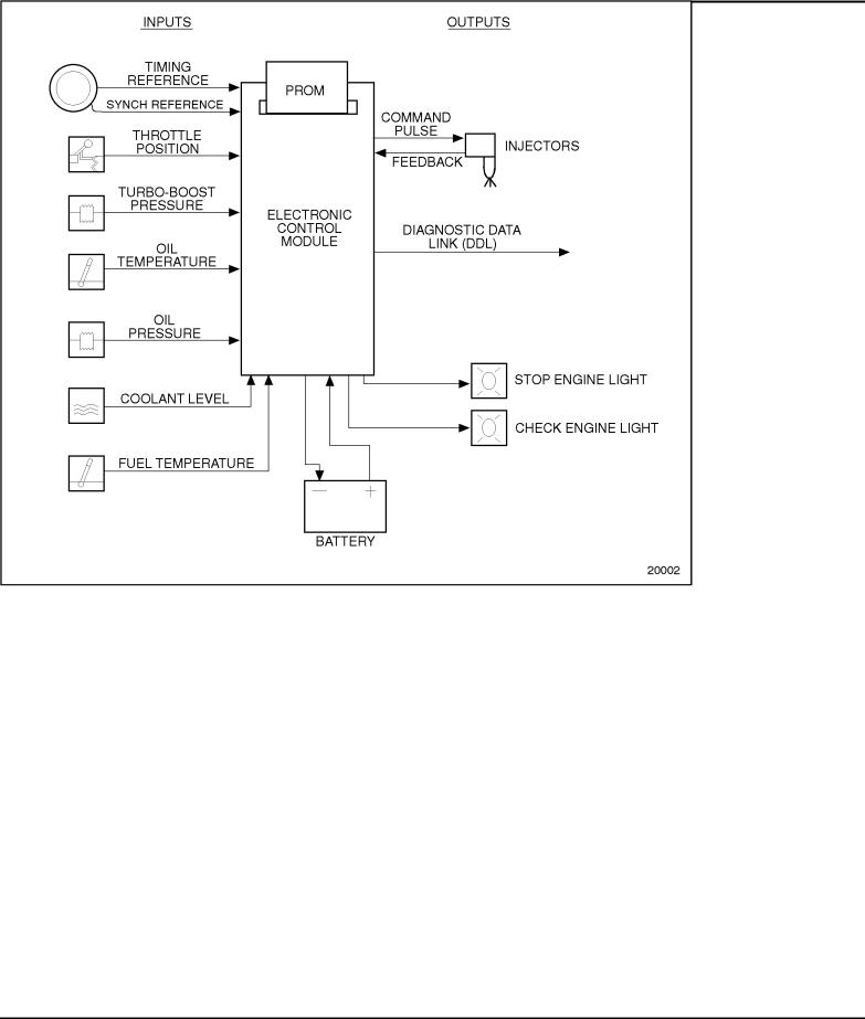
DDEC I controls the timing and amount of fuel injected into each cylinder. The system also monitors several engine functions using various sensors that send electrical signals to the main Electronic Control Module (ECM). See Figure 3. The ECM uses this information to send a command pulse to the Electronic Distributor Unit (EDU). The EDU functions as the high current switching unit for actuation of the Electronic Unit Injector (EUI) solenoids. The ECM also has the ability to limit or shut down the engine completely (depending on option selection) in the case of damaging engine conditions, such as low oil pressure, low coolant level, or high oil temperature.
|
|
Figure 3 |
DECC I |
All information subject to change without notice.
16 |
6SE379 0303 Copyright © 2003 DETROIT DIESEL CORPORATION |
SERIES 92 SERVICE MANUAL
DDEC II
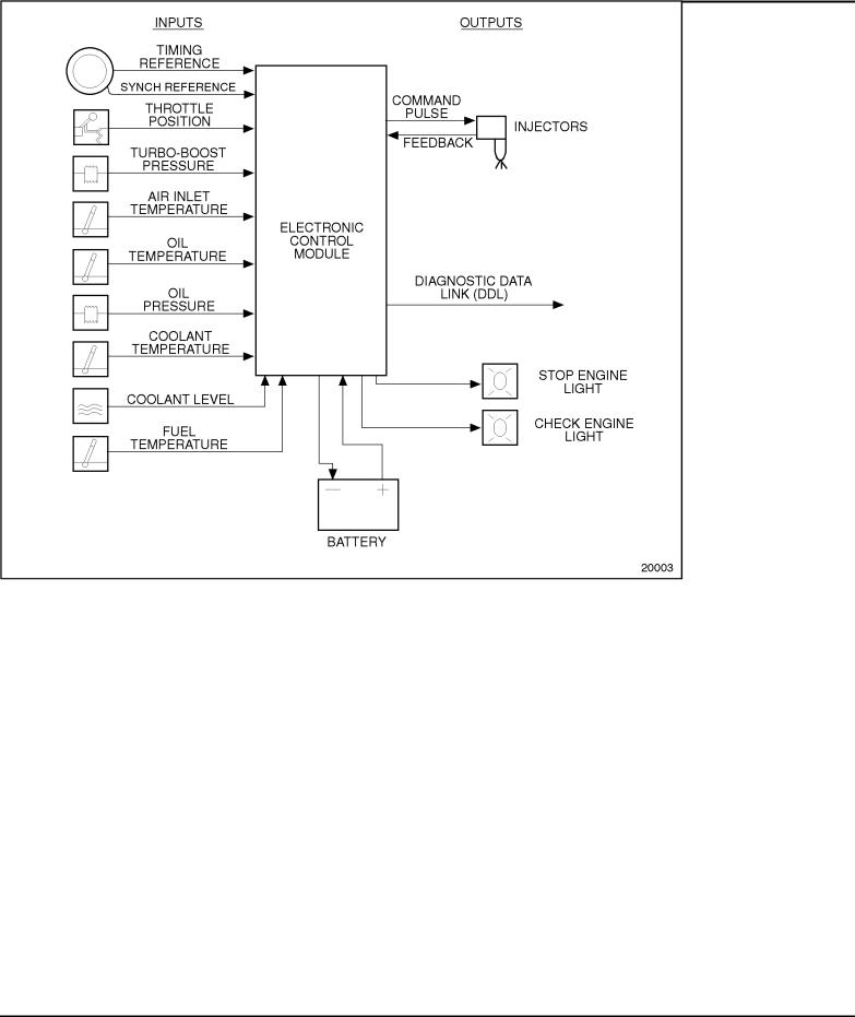
DDEC II also controls the timing and amount of fuel injected into each cylinder. The system also monitors several engine sensors that send electrical signals to the main ECM. See Figure 4. Unlike DDEC I, the DDEC II ECM uses this information to actuate the EUI solenoids. DDEC II incorporates all control electronics into one engine mounted ECM instead of the ECM and EDU that are required in DDEC I. The ECM also has the ability to limit or shut down the engine completely (depending on option selection) in the case of damaging engine conditions, such as low oil pressure, low coolant level, or high oil temperature.
|
|
Figure 4 |
DECC II |
DDEC III
The DDEC III ECM receives electronic inputs from sensors on the engine and vehicle and uses the information to control engine operation. It computes fuel timing and fuel quantity based upon predetermined calibration tables in its memory.
All information subject to change without notice.
6SE379 0303 Copyright © 2003 DETROIT DIESEL CORPORATION |
17 |
SERIES 92 SERVICE MANUAL
Fuel is delivered to the cylinders by the EUI solenoids, which are cam-driven to provide the mechanical input for pressurization of the fuel. The ECM controls solenoid operated valves in the EUIs to provide precise fuel delivery. See Figure 5.
|
|
Figure 5 |
DECC III |
Portable equipment facilitates access to DDEC III's diagnostic capabilities. The Diagnostic Data Reader (DDR) requests and receives engine data and diagnostic codes. This equipment provides many unique capabilities including cylinder cutout, parameter vs. engine speed (or time), printer output, and data snapshot. The DDR also provides limited programming capability.
GENERAL SPECIFICATIONS
The general specifications for the Series 92 Engine are listed in Table 1. See Figure 6 for the cylinder designation and firing order.
All information subject to change without notice.
18 |
6SE379 0303 Copyright © 2003 DETROIT DIESEL CORPORATION |
 Loading...