


Operation and Maintenance
Instructions Manual
DDFP SERIES ENGINES
FOR
FIRE PUMP APPLICATIONS
This manual covers Detroit Diesel engines modified by Clarke DD-A
for fire pump service
LISTED |
FM APPROVED |
LISTED |
Printed in U.S.A. |
C13194 |
MP-4 7/96 |

|
ABBREVIATIONS |
AC |
Alternating Current |
AEC |
Automatic Engine Controller |
API |
American Petroleum Institute |
CCW |
Counter-clockwise engine rotating (front view) |
CDD-A |
Clarke Detroit Diesel-Allison |
CW |
Clockwise engine rotation (front view) |
DC |
Direct Current |
DDC |
Detroit Diesel Corporation |
DDFP |
Detroit Diesel Engines approved for Fire Pump Service |
|
as certified by FM/UL/ULC for Clarke Detroit Diesel-Allison |
FM |
Factory Mutual Research |
GM |
General Motors Corporation |
ID |
Identification |
IP |
Instrument Panel |
I-53 |
In-Line Cylinder arrangement 53 Series DDC Engine |
I-71 |
In-Line Cylinder arrangement 71 Series DDC Engine |
NA |
Naturally Aspirated |
NC |
Normally Closed |
NO |
Normally Open |
NFPA |
National Fire Protection Association |
P/N |
Part Number |
PSI |
Pounds Per Square Inch |
PTO |
Power Take Off |
RPM |
Revelutions Per Minute |
SAE |
Society of Automotive Engineers |
S/N |
Serial Number |
TTurbocharged
TA |
Turbocharged and Aftercooled |
|
UL |
Underwriters Laboratories Inc. |
|
ULC |
Underwriters Laboratories of Canada |
|
V-92 |
Vee cylinder arrangement 92 Series DDC engines |
|
V-71 |
Vee cylinder arrangement 71 Series DDC engines |
|
LISTED |
FM |
LISTED |
APPROVED |
||

TABLE OF CONTENTS |
|
SUBJECT |
PAGE |
ABBREVIATIONS........................................................................................................................................ |
Inside Front Cover |
DESCRIPTION — Section 1 |
|
Principles of Operation .................................................................................................................................................... |
1 |
General Description .......................................................................................................................................................... |
2 |
Model and Serial Number Designation ............................................................................................................................ |
3 |
Engine Equipment ............................................................................................................................................................ |
4 |
FM/UL Nameplate ............................................................................................................................................................ |
5 |
General Specifications ...................................................................................................................................................... |
6 |
OPERATING INSTRUCTIONS — Section 2 |
|
Engine Start-Up and Operating Instructions .................................................................................................................... |
8 |
Standard Model Views .................................................................................................................................................... |
9 |
Electronic Speed Switch .................................................................................................................................................. |
10 |
Preventative Maintenance Schedule.................................................................................................................................. |
11 |
ENGINE SYSTEMS — Section 3 |
|
Fuel System — Section 3.1 .............................................................................................................................................. |
12 |
Operation.................................................................................................................................................................... |
12 |
Maintenance & Service Procedures .......................................................................................................................... |
15 |
Fuel System Schematic.............................................................................................................................................. |
14 |
Air Intake and Exhaust System — Section 3.2 ................................................................................................................ |
16 |
Air System Operation ................................................................................................................................................ |
16 |
Maintenance & Service Procedures .......................................................................................................................... |
19 |
Exhaust Operation...................................................................................................................................................... |
19 |
Lubrication System — Section 3.3 .................................................................................................................................. |
20 |
Operation.................................................................................................................................................................... |
20 |
Lubricating System Schematics ................................................................................................................................ |
21 |
Maintenance & Service Procedures .......................................................................................................................... |
22 |
Cooling System — Section 3.4 ........................................................................................................................................ |
25 |
Operation.................................................................................................................................................................... |
25 |
Maintenance & Service Procedures .......................................................................................................................... |
30 |
Electrical System — Section 3.5 ...................................................................................................................................... |
31 |
Operation.................................................................................................................................................................... |
31 |
Maintenance & Service Procedures .......................................................................................................................... |
35 |
DC Wiring Diagram.............................................................................................................................................. |
37, 38 |
Engine Heater AC Wiring Diagram .......................................................................................................................... |
39 |
Falk Drive Coupling Instructions — Section 3.6 ............................................................................................................ |
40 |
Installation Procedures .............................................................................................................................................. |
41 |
ENGINE TUNE-UP — Section 4 |
|
Tune Up ............................................................................................................................................................................ |
46 |
TECHNICAL DATA — Section 5 .......................................................................................................................................... |
47 |
PARTS INFORMATION — Section 6 |
|
Basic Engine Parts ............................................................................................................................................................ |
48 |
Standard Option Parts ...................................................................................................................................................... |
49 |
OWNER ASSISTANCE — Section 7 ............................................................................................................................ |
50, 51 |
WARRANTY — Section 8 ................................................................................................................................................ |
52, 53 |
STORAGE — Section 9 .......................................................................................................................................................... |
54 |
ALPHABETICAL INDEX — Section 10 .......................................................................................................................... |
55, 56 |

SECTION 1 |
|
|
|
|
|
|
|
|
|
|
|
|
|
|
|
|
|
|
|
|
|
DDFP |
||||||||||
|
|
|
|
|
|
|
|
|
|
|
PRINCIPLES OF OPERATION |
|
|
|
|
|
|
|
|
|
||||||||||||
|
|
|
|
|
|
|
|
|
|
|
|
|
|
|
|
|
|
|
|
|
|
|
|
|
|
|
|
|
|
|
|
|
|
|
|
|
|
|
|
|
|
|
|
|
|
|
|
|
|
|
|
|
|
|
|
|
|
|
|
|
|
|
|
|
|
|
|
|
|
|
|
|
|
|
|
|
|
|
|
|
|
|
|
|
|
FUEL |
|
|
|
|
|
|
|
|
|
|||
|
|
|
|
|
|
|
|
|
|
|
|
|
|
|
|
|
|
|
|
|
|
|
|
|
|
|
|
|
|
|
|
|
|
|
|
|
|
|
AIR |
|
|
|
|
|
|
|
|
|
|
|
|
|
|
|
|
|
|
|
|
|
|
|
|
||
|
|
|
|
|
|
|
|
AIR |
|
|
|
|
|
|
|
|
|
|
|
|
|
AIR |
|
|
|
|
|
|
|
|||
|
|
|
|
|
|
|
|
|
|
|
|
|
|
|
AIR |
|
|
|
|
|
|
|
|
|
|
|
|
|
|
|||
|
|
|
|
|
|
|
|
|
|
|
|
|
|
|
|
|
|
|
|
|||||||||||||
|
AIR |
|
|
|
|
|
|
|
|
|
|
|
|
|
|
|
|
|
|
|
|
|
|
|
|
|
|
|
||||
|
|
|
|
|
|
|
|
|
|
|
|
|
|
|
|
|
|
|
|
|
|
|
|
|
|
|
|
|
|
|||
|
|
|
|
|
|
|
|
|
|
|
|
|
|
|
|
|
|
|
|
|
|
|
|
|
|
|
|
|
|
|||
|
|
|
|
|
|
|
|
|
|
|
|
|
|
|
|
|
|
|
|
|
|
|
|
|
|
|
|
|
|
|
|
|
Scavenging |
|
|
Compression |
|
|
Power |
|
Exhaust |
|
|
|
|||||||||||||||||||||
|
|
|
|
|
|
|
|
|
|
|
|
|
|
|
|
|
|
|
|
|
|
|
11826 |
|
||||||||
|
|
|
|
|
|
|
|
|
|
|
|
|
|
|
|
|
|
|
|
|
|
|
|
|
|
|
|
|
|
|
||
|
|
|
|
|
|
|
|
|
|
|
Fig. 1 |
- In-Line Cylinder Arrangement |
|
|
|
|
|
|
|
|
|
|||||||||||
|
|
|
|
|
|
|
|
|
|
|
|
|
|
|
|
|
|
|
|
|
|
|
|
|
|
|
|
|
||||
|
|
|
|
|
|
|
|
|
|
|
|
|
|
|
|
|
|
|
|
|
|
|
|
|
|
|
|
|
||||
|
|
|
|
|
|
|
|
|
|
|
|
|
|
|
|
|
AIR |
|
|
|
|
|
|
|
|
|
||||||
|
|
|
AIR |
|
|
|
|
|
|
|
|
AIR |
|
|
|
|
|
|
|
|
|
|
AIR |
|
|
|
||||||
|
|
|
|
|
|
|
|
|
|
|
|
|
|
|
|
|
|
|
|
|
|
|||||||||||
|
|
|
|
|
|
|
|
|
|
|
|
|
|
|
|
|
|
|
|
|
|
|
|
|
|
|
|
|
|
|
|
|
|
|
|
|
|
|
|
|
|
|
|
|
|
|
|
|
|
|
|
|
|
|
FUEL |
|
|
|
|
|
|
|
|
|
|
|
|
|
|
|
|
|
|
|
|
|
|
|
|
|
|
|
|
|
|
|
|
|
|
|
|
|
|
|
|
|
|
|
|
|
|
|
|
AIR |
|
|
|
|
|
|
|
|
|
|
|
|
|
|
|
|
|
|
|
|
|
||||||
|
|
|
|
|
|
|
|
|
|
|
|
|
|
|
|
|
|
|
|
|
|
|
|
|
|
EXHAUST |
|
|
|
|||
SCAVENGING |
|
|
COMPRESSION |
|
|
POWER |
|
|
EXHAUST |
|
|
|
||||||||||||||||||||
|
|
|
|
|
|
|
|
|
|
|
|
|
|
|
|
|
|
|
|
|
|
|
12240 |
|
||||||||
|
|
|
|
|
|
|
|
|
|
|
|
|
|
|
|
|
|
|
|
|
|
|
|
|
|
|
||||||
|
|
|
|
|
|
|
|
|
|
|
Fig. 2 - |
Vee Block Cylinder Arrangement |
|
|
|
|
|
|
|
|
|
|||||||||||
The diesel engine is an internal comb ustion power unit, in |
The unidirectional flow of air toward the exhaust valves pro- |
|||||||||||||||||||||||||||||||
which the heat of fuel is converted into work in the cylinder |
duces a scavenging effect, leaving the cylinders full of clean |
|||||||||||||||||||||||||||||||
of the engine. |
|
|
|
|
|
|
|
|
air when the piston again covers the inlet ports. |
|
|
|
||||||||||||||||||||
In the diesel engine, air alone is compressed in the cylinder; |
As the piston continues on the upw ard stroke, the exhaust |
|||||||||||||||||||||||||||||||
then, after the air has been compressed, a charge of fuel is |
valves close and the charge of fresh air is subjected to com- |
|||||||||||||||||||||||||||||||
sprayed into the c ylinder and ignition is accomplished by |
pression (Fig. 1 & 2 - Compression). |
|
|
|
||||||||||||||||||||||||||||
the heat of compression. |
|
|
|
|
|
|
|
|
Shortly before the piston reaches its highest position, |
|
the |
|||||||||||||||||||||
|
|
|
|
|
|
|
|
|
|
|
|
|
|
|
|
|||||||||||||||||
The Two-Cycle Principle |
|
|
|
|
|
|
|
|
required amount of fuel |
is sprayed into the comb |
|
ustion |
||||||||||||||||||||
In the tw o-cycle engine, intake and e xhaust functions tak e |
chamber by the unit fuel injector (Fig. 1 & 2 - Po wer). The |
|||||||||||||||||||||||||||||||
intense heat generated during the high compression of the |
||||||||||||||||||||||||||||||||
place during part of the compression and po wer strokes re- |
||||||||||||||||||||||||||||||||
spectively (Fig. 1) or (Fig. |
|
2). In contrast, |
a four -cycle air ignites the f ine fuel spray immediately. The combustion |
|||||||||||||||||||||||||||||
engine requires four piston strokes to complete an operating |
continues until the fuel injected has been b urned. |
|
|
|
||||||||||||||||||||||||||||
cycle; thus, during one half of its operation, the four-cycle |
The resulting pressure forces the piston do wnward on its |
|||||||||||||||||||||||||||||||
engine functions merely as an air pump. |
|
|||||||||||||||||||||||||||||||
|
power stroke. The exhaust valves are again opened when the |
|||||||||||||||||||||||||||||||
A blo wer is pro vided to |
force air into the c |
ylinders |
for piston is about half way down, allowing the burned gases to |
|||||||||||||||||||||||||||||
expelling the exhaust gases and to supply the cylinders with |
escape into the e xhaust manifold (Fig. 1 & 2 - Exhaust). |
|||||||||||||||||||||||||||||||
fresh air for combustion. The cylinder wall contains a row of |
Shortly thereafter, the do wnward mo ving piston unco vers |
|||||||||||||||||||||||||||||||
ports which are above the piston when it is at the bottom of |
the inlet ports and the c |
ylinder is again swept with clean |
||||||||||||||||||||||||||||||
its stroke. These ports admit the air from the blower into the |
scavenging air. This entire combustion cycle is completed in |
|||||||||||||||||||||||||||||||
cylinder as soon as the rim of the piston unco vers the ports |
each cylinder for each re volution of the crankshaft, |
or, in |
||||||||||||||||||||||||||||||
(Fig. 1 & 2 - Scavenging). |
|
|
|
|
|
|
|
|
other words, in two strokes; hence, it is a "two-stroke cycle". |
|||||||||||||||||||||||
Page 1

y
-

SECTION 1 |
DDFP |
The DDFP model n umber appears on the FM/UL/ULC ta g attached to the right rear of the engine flywheel housing. The DDC basic engine model number appears on the engine rock-
er cover. The engine S/N should be the same a t both locations.
On some engines, you may find different engine rated horsepower and oper ating RPM on the r ocker cover name pla te than on the FM/UL/ULC ta g attached to the f lywheel housing. The FM/UL/ULC tag is the official power data and takes presi-dence over the rocker cover data.
|
D D F P — L 6 V T |
|
|
8 0 6 4 — 7 4 1 2 |
|
|
||||||||||||||||||||||||||||||||||||||||||
|
|
|
|
|
|
|
|
|
|
|
|
|
|
|
|
|
|
|
|
|
|
|
|
|
|
|
|
|
|
|
|
|
|
|
|
|
|
|
|
|
|
|
|
|
|
|
|
|
|
|
|
|
|
|
|
|
|
|
|
|
|
|
|
|
|
|
|
|
|
|
|
|
|
|
|
|
|
|
|
|
|
|
|
|
|
|
|
|
|
|
|
|
|||||
|
|
|
|
|
|
|
|
|
|
|
|
|
|
|
|
|
|
|
|
|
|
|
|
|
|
|
|
|
|
|
|
|
|
|
|
|
|
|
|
|
|
|
|
|
|
|
|
|
|
|
|
|
|
|
|
|
|
|
N |
Naturally Aspirated |
|
|
|
|
|
|
|
|
|
|
|
|
|
|
|
|
|
|
|
|
|
|
|
|
|
|
|||||||||||
|
|
|
|
|
|
|
|
|
|
|
|
|
|
|
|
|
|
|
|
|
|
|
|
|
|
|
|
|
|
|
|
|
|
|||||||||||||||
|
|
|
|
|
|
|
|
|
|
T |
Turbocharged |
|
|
|
|
|
|
|
|
|
|
|
|
|
|
|
|
|
|
|
|
|
|
|
|
|
|
|||||||||||
|
|
|
|
|
|
|
|
|
|
A |
Turbocharged & Aftercooled |
|
|
|
|
|
|
|
|
|
|
|
|
|
|
|
|
|
|
|
|
|
|
|
|
|
Specific Engine For |
|||||||||||
|
|
|
|
|
|
|
|
|
|
H |
High Output |
|
|
|
|
|
|
|
|
|
|
|
|
|
|
|
|
|
|
|
|
|
|
|
|
|
||||||||||||
|
|
|
|
|
|
|
|
|
|
|
|
|
|
|
|
|
|
|
|
|
|
|
|
|
|
|
|
|
|
|
|
|
|
|
Fire Pump Application |
|||||||||||||
|
|
|
|
|
|
|
|
|
|
|
|
|
|
|
|
|
|
|
|
|
|
|
|
|
|
|
|
|
|
|
|
|
|
|
|
|
|
|
|
|
|
|
|
|
|
|
|
|
|
|
|
|
|
|
|
|
|
|
A |
71 Series DDC Engine, In-Line |
|
|
|
|
|
|
|
|
|
|
|
|
|
|
|
|
|
|
|
|
|
|
|
|
|
|
|||||||||||
|
|
|
|
|
|
|
|
|
|
D |
53 Series DDC Engine |
|
|
|
|
|
|
|
|
|
|
|
|
|
|
|
|
|
|
0 |
|
NA Engine |
||||||||||||||||
|
|
|
|
|
|
|
|
|
|
|
|
|
|
|
|
|
|
|
|
|
|
|
|
|
|
|
||||||||||||||||||||||
|
|
|
|
|
|
|
|
|
|
F |
92 Series DDC Engine |
|
|
|
|
|
|
|
|
|
|
|
|
|
3 |
|
Turbocharged |
|||||||||||||||||||||
|
|
|
|
|
|
|
|
|
|
V |
71 Series DDC Engine, Vee |
|
|
|
|
|
|
|
|
|
|
|
|
|
4 |
|
Turbo & Aftercooled |
|||||||||||||||||||||
|
|
|
|
|
|
|
|
|
|
|
|
|
|
|
|
|
|
|
|
|
|
|
|
|||||||||||||||||||||||||
|
|
|
|
|
|
|
|
|
|
(X) |
Number of Cylinders |
|
|
|
|
|
|
|
|
|
|
|
|
|
6 |
|
Turbo & Aftercooled |
|||||||||||||||||||||
|
|
|
|
|
|
|
|
|
|
|
|
|
|
|
|
|
|
|
|
|
|
|
|
|
|
|
|
|
|
|
3 |
LH Rotation |
||||||||||||||||
|
|
|
|
|
|
|
|
|
|
|
|
|
|
|
|
|
|
|
|
|
|
|
|
|
|
|
|
|
|
|||||||||||||||||||
|
|
|
|
|
|
|
|
|
|
|
|
|
|
|
|
|
|
|
|
|
|
|
|
|
|
|
|
|
|
|
|
|
|
|
|
|
|
|
|
|||||||||
|
|
|
|
|
|
|
|
|
|
O |
Basic Build Level |
|
|
|
|
|
|
|
|
|
|
|
|
7 |
RH Rotation |
|||||||||||||||||||||||
|
|
|
|
|
|
|
|
|
|
|
|
|
|
|
|
|
|
|
|
|
|
8 |
RH Rotation |
|||||||||||||||||||||||||
|
|
|
|
|
|
|
|
|
|
L |
Reduced Output Build |
|
|
|
|
|
|
|
|
|
|
|
|
|||||||||||||||||||||||||
|
|
|
|
|
|
|
|
|
|
|
|
|
|
|
|
|
|
|
|
|
|
|
|
|
|
|
|
|
|
|
|
|
|
|
|
|||||||||||||
|
|
|
|
|
|
|
|
|
|
T |
Alternate Turbo |
|
|
|
|
|
|
|
|
|
|
|
|
|
|
Industrial Power Unit |
||||||||||||||||||||||
|
|
|
|
|
|
|
|
|
|
I |
Included With Number of Cylinders |
|
|
|
|
|
|
|
|
|
|
|
|
|
|
|||||||||||||||||||||||
|
|
|
|
|
|
|
|
|
|
|
|
|
|
|
|
|
|
|
|
|
|
|
|
|
|
|
|
|
|
|
|
|
|
|
|
|||||||||||||
|
|
|
|
|
|
|
|
|
|
on |
|
Engines With 10 or more Cylinders |
|
|
|
|
|
|
|
|
|
|
|
XX |
|
|
|
|
Number of Cylinders |
|||||||||||||||||||
|
|
|
|
|
|
|
|
|
|
|
|
|
|
|
|
|
|
|
|
|
|
|
|
|
|
|
|
|
|
|||||||||||||||||||
|
|
|
|
|
|
|
|
|
|
|
|
|
|
|
|
|
|
|
|
|
|
|
|
|
|
|
|
|
|
|
|
|
|
|
|
|
|
|
|
|
||||||||
|
|
|
|
|
|
|
|
|
|
Detroit Diesel Engines |
|
|
|
|
|
|
|
|
|
|
1 |
|
|
|
|
71 Series DDC Engine, In-Line |
||||||||||||||||||||||
|
|
|
|
|
|
|
|
|
|
|
|
|
|
|
|
|
|
|
||||||||||||||||||||||||||||||
|
|
|
|
|
|
|
|
|
|
|
|
|
|
|
|
|
|
|
||||||||||||||||||||||||||||||
|
|
|
|
|
|
|
|
|
|
|
5 |
|
|
|
|
53 Series DDC Engine |
||||||||||||||||||||||||||||||||
|
|
|
|
|
|
|
|
|
|
Modified by Clarke and |
|
|
|
|
|
|||||||||||||||||||||||||||||||||
|
|
|
|
|
|
|
|
|
|
|
7 |
|
|
|
|
71 Series DDC Engine, Vee |
||||||||||||||||||||||||||||||||
|
|
|
|
|
|
|
|
|
|
Certified by FM/UL/ULC for |
|
|
|
|
|
|||||||||||||||||||||||||||||||||
|
|
|
|
|
|
|
|
|
|
|
8 |
|
|
|
|
92 Series DDC Engine |
||||||||||||||||||||||||||||||||
|
|
|
|
|
|
|
|
|
|
Fire Pump Service |
|
|
|
|
|
|||||||||||||||||||||||||||||||||
|
|
|
|
|
|
|
|
|
|
|
|
|
|
|
|
|
|
|
|
|
|
|
|
|
|
|
|
|
|
|
|
|
|
|
|
|||||||||||||
|
|
|
|
|
|
Figure 3 - Clarke FM/UL/ULC Model |
|
|
|
|
|
|
|
|
|
|
|
Figure 4 - DDC Basic Engine Model |
||||||||||||||||||||||||||||||
|
|
|
|
|
|
|
|
|
|
|
|
|
|
|
|
|
|
|
|
|
|
|
|
|
|
|
|
|
|
|
|
|
|
|
|
|
|
|
|
|
|
|
|
|
|
|
|
|
(See Page 1)
Page 3

SECTION 1 |
DDFP |
DDFP STANDARD ENGINE EQUIPMENT LIST
—Air cleaner, oiled gauze or dry type for protected envi- |
—Junction box (DC control) for connection to engine |
ronment. |
controller |
—Battery charging alternator (12 or 24V-DC) negative |
—Low oil pressure switch |
ground |
|
|
—Manual over-ride of automatic operations including |
—Engine coolant heater with AC power connection (120, |
instruction plate |
208 or 240V) |
|
—Engine oil cooler |
—Manual start contactors - two provided on each engine |
|
|
—Electric starting motor (12 or 24V-DC) |
—Oil filter(s) full flow with by-pass |
|
|
—Exhaust manifold insulation or heat shield |
—Oil pan heater (optional) |
|
|
—Fuel inlet check valve |
—Overspeed control and reset switch |
|
|
—Fuel filters - Primary and Secondary |
—Solenoid Run/Stop control-signal from AEC |
|
|
—Governor speed control |
—Direct mounted engine half of Falk coupling |
|
|
(10% No Load to Full Load) |
—Tachometer with hour meter |
|
|
—Heat Exchanger with pressure cap |
—Tamper proof throttle control factory preset |
|
|
—High water temperature switch |
—Wiring harness for DC control |
|
|
—Instrument panel with water temperature, oil pressure |
|
and voltmeter |
|
Page 4
SECTION 1 |
DDFP |
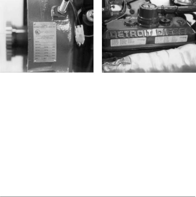
FM/UL/ULC CERTIFICATION NAME PLATE
The standard nameplate (Fig. 5) contains the follo wing information: FM/UL certified model number; Clark e specification number; production date; rated horsepower; full load engine speed; basic engine serial number (S/N). The name plate is located on the right rear of the engine and attached to the flywheel housing.
The DDC model and S/N are found on the manuf acturer's I.D. label (Fig. 6) on the v alve rocker cover. This model is also stamped on the engine block.
On the Inline engines, the model number is stamped into the cylinder block casting on a machined pad abo ve and to the right of the engine blower. On the VEE engines, the number is stamped at the right front of the block just behind the water pump.
When requested, a ULC nameplate is provided in addition to the FM & UL nameplate. This plate is mounted separately on the engine.
Figure 5 |
Figure 6 |
Page 5

SECTION 1 |
|
|
|
DDFP |
|
|
|
|
|
|
General Specifications - DDFP Models |
|
|
|
|
|
|
|
|
|
03DN |
|
|
|
|
03DT |
|
|
|
|
L3DT |
|
04AN |
L6VT |
|
T3DT |
03AN |
04AT |
T6VT |
Type |
2 Cycle |
2 Cycle |
2 Cycle |
2 Cycle |
Number of Cylinders |
3 |
3 |
4 |
6 |
Bore (inches) |
3.875 |
4.25 |
4.25 |
4.25 |
Bore (mm) |
98 |
108 |
108 |
108 |
Stroke (inches) |
4.5 |
5 |
5 |
5 |
Stroke (mm) |
114 |
127 |
127 |
127 |
Compression Ration (T Eng) |
18.7:1 |
– – |
17:1 |
17:1 |
Compression Ration (N Eng) |
21.0:1 |
18.7:1 |
18.7:1 |
– – |
Total Displacement (cub. in.) |
159 |
213 |
284 |
426 |
Total Displacement (liters) |
2.61 |
3.49 |
4.66 |
6.99 |
Number of Main Bearings |
4 |
4 |
5 |
4 |
|
|
|
|
|
General Specifications - DDFP Models
|
|
|
L8FA |
|
|
|
|
06FA |
06FH |
08FA |
08FH |
12FT |
12FH |
Type |
2 Cycle |
2 Cycle |
2 Cycle |
2 Cycle |
2 Cycle |
2 Cycle |
Number of Cylinders |
6 |
6 |
8 |
8 |
12 |
12 |
Bore (inches) |
4.84 |
4.84 |
4.84 |
4.84 |
4.84 |
4.84 |
Bore (mm) |
123 |
123 |
123 |
123 |
123 |
123 |
Stroke (inches) |
5 |
5 |
5 |
5 |
5 |
5 |
Stroke (mm) |
127 |
127 |
127 |
127 |
127 |
127 |
Compression Ratio |
17:1 |
15:1 |
17:1 |
15:1 |
17:1 |
15:1 |
Total Displacement (cubic inches) |
552 |
552 |
736 |
736 |
1104 |
1104 |
Total Displacement (liters) |
9.05 |
9.1 |
12.07 |
12.07 |
18.1 |
18.1 |
Number of Main Bearings |
4 |
4 |
5 |
5 |
8 |
8 |
For Specific Operational Data For Each Engine Model, Refer To Technical Data Section 5.
Page 6
SECTION 1 |
DDFP |
|
|
|
|
|
|
|
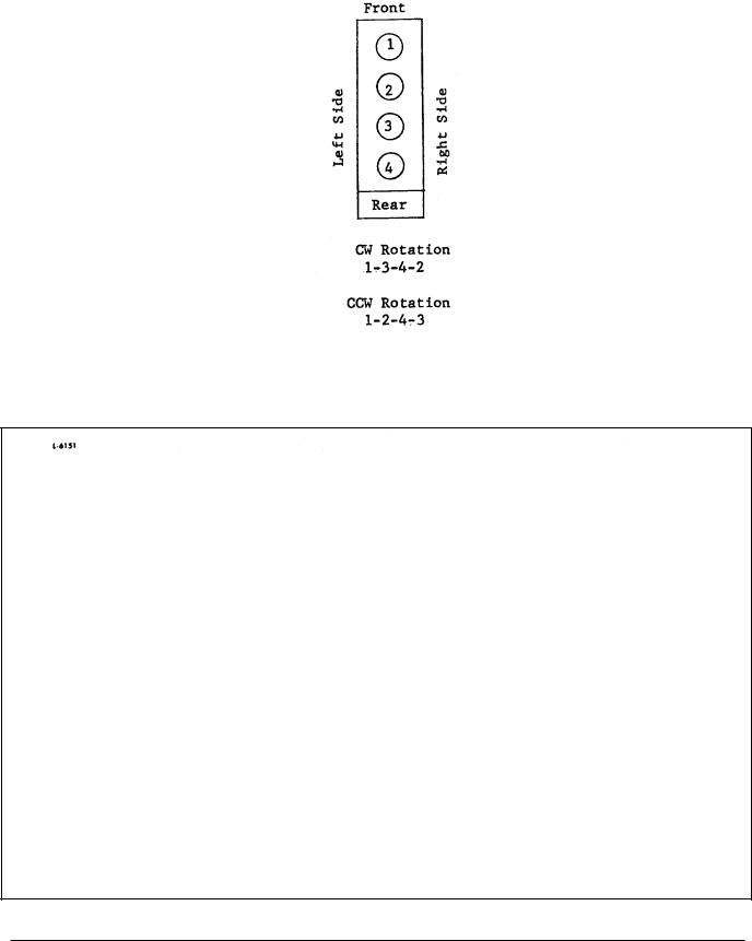
3 - IN-LINE |
4 - IN-LINE |
|
|
|
|
|
Fig. 7 - Cylinder Designation and Firing Order
Fig. 8 VEE Engine Cylinder Designation and Firing Order
Page 7
SECTION 2 |
DDFP |
ENGINE START UP AND OPERATING INSTRUCTIONS
Preparing New Engine For Start-Up
Before starting a new or overhauled engine for the first time, carefully read and follow the check list below. Attempting to run the engine before studying these instructions may result in serious damage to the engine.
1.Make all electrical (DC) connections between engine (DC) junction box and engine controller.
2.Make all raw water connections to heat exchanger tank. Discharge line should be one size larger than supply line and rise a minimum of 3 inches abo ve heat e xchange outlet to assure complete co verage of the heat e xchange core. Discharge water is to be piped to an open w aste cone.
NOTE: Do not allo w raw water plumbing to stress on engine heat exchanger.
3.Install all of the drain cocks or plugs in the cooling system (drain cocks are removed for shipping engines dry).
4.Fill engine cooling system with PRE-MIXED 50 per - cent water and 50 percent permanent type antifreeze solution. Fill to top heat exchanger tank.
NOTE: Refer to Section 3.4 for Cooling System Fill Procedure.
5. Connect fuel supply line and fuel return line to supply tank. Bleed fuel system of all air.
NOTE: Do not use galvanized material for any component part of a diesel fuel system. The fuel will chemically react with the zinc coating.
6. Fill fuel tank with No. 2 diesel fuel.
NOTE: No. 2 diesel fuel is the only recommended fuel, engine po wer could be af fected by using an y other type.
7.Fill engine crankcase with SAE 40 weight oil per oil recommendations of Section 3. Oil filler locations v ary by engine model. Most will be found on the engine valve cover.
8.Pre-lubricate engine to a minimum 25 psi (172 KPA) to insure an immediate flow of oil to all bearings at the initial engine start-up. Contact the authorized DDC Distributor/Dealer if you require assistance with this item.
9.Unbox and inspect air cleaner element for damage or deterioration. Install air cleaner element on engine.
10.Install batteries, battery cables and service batteries as required by manufacturer. See battery recommendation under Section 3.
11.Install exhaust system. A vertical exhaust outlet is furnished for customer/contractor installation. A fle xible e x- haust connector must be installed at outlet.
NOTE: Do not exceed exhaust back pressure limits. See Section 5 for details for each engine model.
NOTE: Do not allow exhaust system plumbing to stress on engine.
If any problems or questions develop in performing the above procedures, advise the authorized DDC Distributor/Dealer of details when making arrangements for the installation inspection.
NOTE: Only one initial start-up inspection is provided at no charge for an installation re view. Be sure to cover items 1-11 thoroughly before calling the authorized DDC Distributor/Dealer.
Normal Running
Fire pump engines are run periodically to assure proper operation. Units may be run automatically as programmed within the AEC or the y may be run manually for systems e valuation.
NOTE: For specific operating instructions, see Section 3 - Electrical System.
Normal Care And Maintenance Should Be Made On The Following Systems:
Fuel System
Periodically check fuel tank to assure it is full. Keep the fuel tank f illed to reduce condensation to a minimum and to assure full running time during emergency operation. Engine fuel filter should be changed annually or when fouled with contamination. If contaminated, locate the source and correct. (See Section 3 page 13 for proper procedure). If the engine runs out of fuel or if the eng ine is out of service for a considerable length of time, it may be necessary to reprime the fuel system. Refer to Section 3 for proper procedure.
Page 8
SECTION 2 |
DDFP |
Drive Belts
Adjust the alternator drive belts as recommended under the Preventive Maintenance Section 2.
engine coolant |
between 120 -140 de grees F (49-60° C). |
When running, |
engine coolant temperature should re gister |
between 180-200 de grees F (82-93° C). See Section 3 for detailed information.
Storage Battery
Check the batteries. The top should be clean and dry, the terminals tight and protected, and the electrolyte must be at the proper level. They should be tested weekly to determine the condition of cells, and the amount of charge.
NOTE: Once each week, check the batteries with a hydrometer; the corrected reading should be 1.265 or higher. Hydrometer readings should be corrected for the temperature of the electrolyte. Should a problem be detected, locate source and correct.
Oil Pressure
Normal engine operating oil pressure is 40-70 psi (276-433 kPa). If operating pressure falls below 30 psi (206 kPa), stop engine and investigate cause.
Coolant Temperature
When unit is not running, Jacket w ater heaters maintain
Crankcase
The oil le vel should be maintained between the Full mark and Low mark. Check the oil le vel weekly prior to normal exercise. The oil dipstick is located on the right side of the engine. Do not check oil level when the engine is running. If the engine crankcase was refilled, stop the engine after normal operating temperature has been reached, allow the oil to drain back into the crankcase (approximately 10 minutes) and check the oil le vel. Add oil, if necessary, to bring it to the proper level on the dipstick.
NOTE: DO NOT OVER-FILL CRANKCASE.
Use only the recommended lubricating oil specif ied under Section 3 - Lubricating Oil.
Running Inspection
While the engine is running at operating temperature, check for coolant, fuel or lubricating oil leaks. Tighten the line
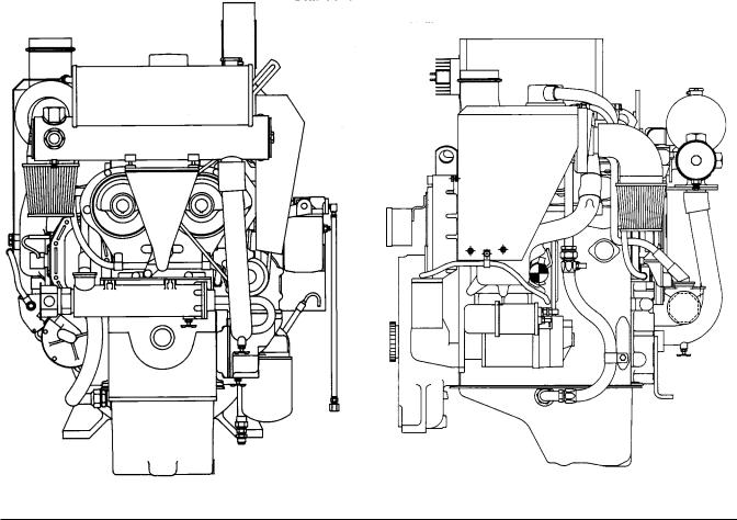
Standard Model Views
Front View (I-53) |
Right Side View (I-53) |
Page 9
SECTION 2 |
DDFP |
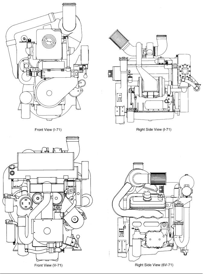
Front View (I-71) |
|
Right Side View (I-71) |
Front View (V-71) |
|
Right Side View (6V-71) |
Page 9-A
SECTION 2 |
DDFP |
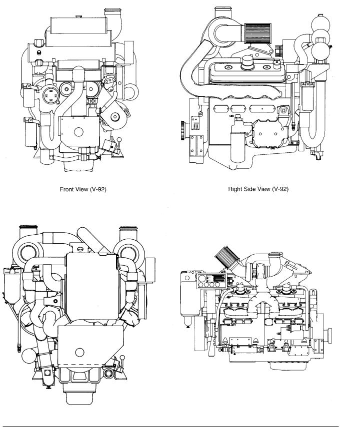
Front View (V-92) |
|
Right Side View (V-92) |
Front View (12V-92) |
Left Side View (12V-92) |
Page 9-B

SECTION 2 |
DDFP |
ELECTRONIC SPEED SWITCH
The speed switch is located on the rear or back side of the instrument panel.
There are two (2) functions built into the speed switch. First to terminate starter cranking, once the engine is running. Second to signal the controller and ef fect an engine shutdown in the event of an engine overspeed condition.
Features of the speed switch are a "manual reset b utton" on the face of the switch, which must be pushed into reset the switch should the engine shutdo wn from an overspeed condition. Additionally, a varification circuit to assist in checking or setting the overspeed set point.
OVERSPEED VARIFICATION
To varify the function of the overspeed signal (SW#2) without overspeeding the engine, install a jumper wire on terminals "C & D" of the speed switch. This will provide the controller with an o verspeed signal and engine shutdo wn at 67% of calibrated RPM.
Start the engine via the controller , the speed switch will effect an overspeed signal and shutdown protecting both the engine and pump.
EXAMPLE
CALIBRATION
Both crank terminate (SW#1) and o verspeed (SW#2) set points, are set at the factory and should not require additional calibration. Adjustments can be made to the set points of SW#1 and/or SW#2 if required using a je welers screw driver. Turning the corresponding adjustment scre w CW to increase or CCW to decrease the set point. To access either adjustment screw remove the small co ver plate on the f ace of the speed switch.
Crank terminate (SW#1) adjustment should be done reading "engine crankshaft" speed at the front of the engine using a hand held tachometer . For starter protection and optimum engine stability, this switch should be calibrated to 1000 RPM.
Overspeed (SW#2) adjustment should be done r eading "engine crankshaft" speed at the front of the engine using a hand held tachometer . This switch should be calibrated to 120% of rated speed, but ne ver higher than 3200 RPM. Refer to the stainless steel nameplate located at the right rear of the engine for the correct rated speed.
Rated Speed : 2100 RPM
Overspeed Shutdown : 2520 RPM (120% of 2100 RPM) Varification Shutdown : 1688 RPM (67% of 2520 RPM)
CAUTION
After v arification of SW#2 the jumper wir e must be removed and the "reset b utton" pushed in to re-instate normal operation of the engine and speed switch.
Page 10

SECTION 2 |
|
|
|
DDFP |
|
|
PREVENTIVE MAINTENANCE SCHEDULE |
|
|
||
|
|
|
|
||
Item |
|
Inspection Interval |
|
||
|
|
Weekly |
6 Months |
1 Year |
2 Year |
|
|
|
|
|
|
1. |
Run Engine |
|
|
|
|
|
(per NFPA 20 Specifications) |
X |
|
|
|
2. |
General Inspection |
X |
|
|
|
3. |
Lubricating Oil |
X |
|
R |
|
4. |
Fuel Tank |
X |
|
|
|
5. |
Fuel Lines |
|
X |
|
|
6. |
Cooling System |
X |
|
|
R |
7. |
Battery |
X |
C |
|
|
8. |
Air Cleaner - Dry Type (-03AN & -04AN) |
|
X |
R |
R |
|
- Oil Gauze (All Other Models) |
|
X |
C |
R |
9. |
Drive Belts |
|
X |
|
|
10. |
Speed Control |
|
X |
|
|
11. |
Fuel & Lube Oil Filters |
|
|
R |
|
12. |
Exhaust System |
X |
X |
|
|
13. |
Battery Charging Alternator |
|
X |
|
|
14. |
Manual Contractors |
|
X |
|
|
15. |
Operating Gauges |
X |
|
|
|
16. |
Crankcase Vent System |
|
|
X |
|
17. |
Heat Exchanger Electrode |
|
|
|
X |
18. |
Governor Run-Stop Mechanism |
|
X |
|
|
19. |
Jacket Water Heater |
X |
|
|
|
20. |
Wiring System |
|
|
X |
|
21. |
Coolant Hose Inspection |
X |
|
|
R |
See Parts Information Section 6 for Lubricating Oil And Coolant Analysis' Kits
IMPORTANT: Set AEC to "of f" while servicing engine. |
"Automatic" position and the manual operating le |
ver to |
|
Before turning the AEC to the "off" position, check with the |
"auto - off" position. |
|
|
maintenance and security supervisors to v erify that all de- |
|
|
|
partments concerned will be alerted of the temporary inter- |
X |
Check |
|
ruption of their f ire protection equipment for normal main- |
R |
Replace |
|
tenance or testing.Also, alert the local fire department in the |
C |
Clean |
|
event that the AEC is connected by silent alarm to head- |
|
|
|
quarters. When servicing is complete,returnAEC selector to |
|
|
|
Page 11

SECTION 3 |
DDFP |
ENGINE SYSTEMS
Section 3.1 |
Fuel System |
Section 3.2 |
Air Intake & Exhaust System |
Section 3.3 |
Lubrication System |
Section 3.4 |
Cooling System |
Section 3.5 |
Electrical System |
Section 3.6 |
Falk Drive Coupling |
In this Engine Systems section that follows, data is presented in a generalized way for a description of system operation. For specific operational data and system limits, refer
to Section 5. In addition to kno wing the specif ic DDFP
model being operated, make special note of the certif ied engine operating speed (RPM). Much of the data v aries by operating RPM - check the FM/UL/ULC certification tag on the engine flywheel housing for this speed.
FUEL SYSTEM
OPERATION
Fuel is drawn from the supply tank through the fuel strainer and enters the fuel pump at the inlet side. Upon lea ving the fuel pump under pressure, the fuel is forced through the fuel filter and into the fuel inlet manifold where it passes through fuel pipes into the inlet side of each fuel injector. The fuel is atomized through small injector spray tip orif ices into the combustion chamber. Surplus fuel, returning from the injectors, passes through the fuel return manifold and connecting fuel lines back to the fuel tank. The continuous flow of fuel through the injectors helps to cool the injectors and to remove air from the fuel system.
CHECK VALVE
A check valve is installed between the fuel filter and the fuel inlet manifold. The check valve is rated to open at approximately 2 psi (13.7 KP A). The fuel tank and supply lines should be arranged to limit static pressure so that the v alve remains closed when unit is not running. This valve opens automatically from fuel pump pressure when the unit starts. Refer to Figure 1, Page 14, for fuel system components.
FUEL INJECTOR
The fuel injector combines in a single unit all of the parts necessary to pro vide complete and independent fuel injection at each c ylinder. The injector creates the high pressure necessary for fuel injection, meters the proper amount of fuel, atomizes the fuel, and times the injection into the combustion chamber.
Since the injector is one of the most important and carefully constructed parts of the engine, it is recommended that the injector be replaced as an assembly if it is not operating properly. An authorized DDC Distributor/Dealer is equipped to pro vide ne w and reconditioned replacement injectors. Under no circumstance should an attempt be made to repair these injectors. Genuine f actory new or "reliabilt" injectors should be used for repairs.
FUEL PUMP
DDFP Engines are equipped with a positi ve displacement gear type fuel transfer pump. Fuel pumps are furnished in either left or right hand rotation according to the engine model, and are stamped RH or LH. These pumps are not interchangeable and cannot be rebuilt to operate in an opposite rotation. The fuel pump used on the 53 series engine is driven by the governor assembly on the left rear . On I-71 it is attached and driven off the rear of the lower engine blower rotor. On VEE engines, the pump is attached and dri ven
off the right front blo wer rotor located on the v ee of the
block.
A spring-loaded relief valve, incorporated in the pump body,
normally remains in the closed position, |
operating |
only |
when the pressure on the outlet side (to the fuel f |
ilter) |
|
becomes excessive due to a plugged filter or fuel line. |
|
|
The fuel pump incorporates two oil seals. Two tapped holes are provided in the underside of the pump body, between the oil seals, to permit a drain tube to be attached. If fuel leakage exceeds one drop per minute,the seals must be replaced. An authorized DDC Distributor/Dealer is properly equipped to replace the seals or to provide reconditioned parts.
Page 12

SECTION 3.1 |
|
|
|
|
|
|
|
|
DDFP |
|
SPIN-ON TYPE FUEL FILTER |
|
|
|
|
|
|
|
|
||
|
|
|
|
|
General Fuel |
ASTM |
No. 2 |
|||
|
|
|
|
|
|
|
|
|||
A spin-on type fuel strainer and fuel filter (Fig. 2) is used on |
|
|
|
Classification |
Test |
ASTM 2-D |
||||
|
|
|
|
|
|
|||||
Clarke DDFP engines. The spin-on f ilter cartridge consists |
|
|
|
|
|
|
||||
of a shell, element and gasket combined into a unitized re- |
|
|
Gravity, °API # |
D 287 |
33 - 37 |
|||||
placement assembly. No separate springs or seats are re- |
|
|
|
|
|
|
||||
quired to support the filters. |
|
|
|
|
|
Flash Point, Min. °F (°C) |
D 93 |
125 (52) |
||
|
|
|
|
|
|
|
||||
The filter base incorporates a threaded slee ve to accept the |
|
|
Viscosity, Kinematic |
D 445 |
1.9 - 4.1 |
|||||
spin-on f ilter cartridges. |
The w |
ord |
"Primary" |
or |
||||||
"Secondary" is cast on the fuel strainer base for identif ica- |
|
|
cST @ 100°F (40°C) |
|
|
|||||
tion. |
|
|
|
|
|
Sulfur Content wt%, Max. |
|
|
||
No drain cocks are pro vided on the spin-on f ilters. Where |
|
|
D 1266 |
0.5 |
||||||
|
|
|
|
|
|
|||||
water is a problem, residue may be drained by removing and |
|
|
Carbon Residue |
D 524 |
0.35 |
|||||
inverting the filter. Refill the filter with clean fuel oil before |
|
|
||||||||
|
|
on 10%, wt%, Max. |
|
|
||||||
reinstalling it. Should water be found, locate the source and |
|
|
|
|
||||||
|
|
|
|
|
|
|||||
correct by draining or cleaning as required. |
|
|
|
|
Accelerated Stability |
D 2274 |
1.5 |
|||
|
|
|
|
|
|
|
||||
Replace the Filter as Follows: |
|
|
|
|
|
Total Insolubles |
|
|
||
1. Unscrew the filter (or strainer) and discard it. |
|
|
|
mg/100 ml, Max. # |
|
|
||||
|
|
|
|
|
|
|
||||
2. |
Fill a new filter replacement cartridge full with clean fuel |
|
|
Ash, wt%, Max. |
D 482 |
0.01 |
||||
|
oil. Coat the seal gasket lightly with clean fuel oil. |
|
|
|
|
|
|
|||
3. |
Install the new filter assembly and tighten it to two-thirds |
|
|
Cetane Number, Min. + |
D 613 |
45 |
||||
|
of a turn beyond gasket contact. |
|
|
|
|
|
|
|
|
|
4. |
Start the engine and check for leaks. |
|
|
|
|
Cetane Index, Min. + |
D 4737 |
40 |
||
NOTE: DDFP engines have the "Primary" filter at or below |
|
|
Distillation Temperature, |
D 86 |
|
|||||
|
the fuel pump. One exception to this is current pro- |
|
|
|
°F (°C) |
|
|
|||
|
duction I-53 engines. Due to f |
actory designed, |
|
IBP, Typical # |
|
375 (191) |
||||
|
formed steel fuel lines, the I-53 filters are mounted |
|
|
|
10% Typical # |
|
430 (221) |
|||
|
the reverse of all others. The Primary Filter mounts |
|
|
|
50% Typical # |
|
510 (256) |
|||
|
to the c ylinder head abo ve |
the |
pump. |
The |
90% + |
|
625 (329) Max. |
|||
|
Secondary filter mounts to the coolant w ater inlet |
|
|
|
End Point # |
|
675 (357) Max. |
|||
|
elbow below the fuel pump. Inlet fuel check valves |
|
|
|
|
|
|
|||
|
are always located on the discharge side of the sec- |
|
|
Water & Sediment |
D 1796 |
0.05 |
||||
|
ondary filter. |
|
|
|
|
|
||||
|
|
|
|
|
|
%, Max. |
|
|
||
|
|
|
|
|
|
|
|
|
||
|
|
|
|
|
|
|
|
|
|
|
DIESEL FUEL RECOMMENDATIONS
The quality and grade of fuel used is a very important factor in obtaining satisf actory engine performance, long engine
life, and acceptable e xhaust emission le vels. Certif ied engine ratings are based at standard SAE conditions using
the recommended #2-D Diesel Fuel. Refer to the Diesel Fuel Specifications chart Fig 3 for verification of fuel properties. For additional information on the fuel system, see technical data Section 5, Page 43. In addition, Sulfur content of the #2 Diesel Fuel used must be limited to 0.5% mass. The com-
# Not Specified in ASTM D 975 ........................................
+ Differs from ASTM D 975
Fig. 3 - Diesel Fuel Specifications Chart
Page 13
SECTION 3.1 |
DDFP |
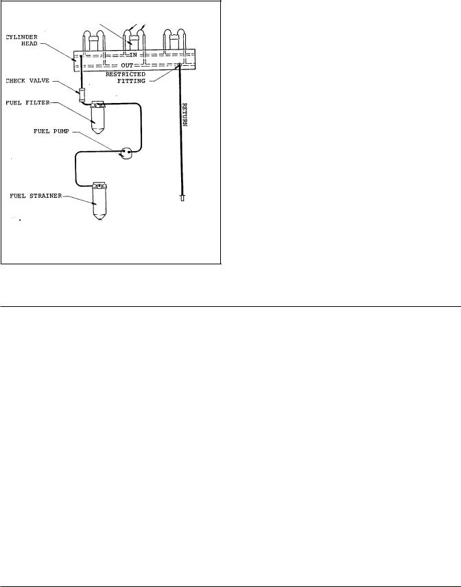
FUEL SYSTEM SCHEMATICS
1. Fuel Strainer (Primary)
2. Fuel Transfer Pump
3. Fuel Filter (Secondary)
4. Check Valves
5. Cylinder Head with Internal Manifolds
6. Fuel Injectors
7. Fuel Pipes (Inlet and Return to Injector)
8. Restricted Fuel Fitting
9. Return to Tank
Fig. 1 - DDFP Fuel System
ENGINE MECHANICAL GOVERNOR
A v ariable speed mechanical go vernor pro vides speed control of the engine. The certified engine speed, shown on FM/UL/ULC label, has been preset at the f actory. Minor speed adjustments can be made in the f ield to meet specific installation condition, generally ± 50 RPM maximum.
The go vernor is controlled by the R UN-STOP solenoid. This solenoid is activated by a signal from the AEC. A manual over-ride switch on the instrument panel, placed in the MANUAL position, allows manual operation should the AEC malfunction.
Note: Always leave the instrument panel switch in the AUTO position when the unit is unattended.
Page 14

SECTION 3.1 |
DDFP |
MAINTENANCE AND SERVICE PROCEDURES
Weekly
1). Fuel Tank: Keep the fuel tank f illed to reduce condensation to a minimum. Open drain at the bottom of the fuel tank once a week to drain of f any possible w ater and/or sediment. Fill tank after each test run.
NOTE: Per NFPA 20 standards, the fuel tank level must never be less than 50% of capacity.
where it is introduced. Microbe growth can start again if fuel is transferred from a treated to an untreated tank. Diesel fuel soluble type, such as "Biobor" manufactured by U.S. Borax or equivalent, treats the fuel itself and therefore the entire fuel system. Please follow manufacturer's recommendations on useage of these materials.
2). Fuel: Use a proper grade of #2-D diesel fuel only .
6 Months
Check condition of fuel lines for fraying, leaks or poor condition. Replace as necessary.
Yearly
Change primary and secondary fuel filters. Refer to Section 6 for recommended part numbers.
DIESEL FUEL CONTAMINATION
The most common form of diesel fuel contamination is water. Water is harmful to the fuel system and it also pr o- motes the growth of microbiological organisms (microbes). These microbes clog fuel f ilters with a "slime" and restrict fuel flow.
Water can be introduced into the fuel supply through poor maintenance (loose or open fuel tank caps), contaminated fuel supply or condensation.
Condensation is particularly prevalent on units which stand idle for e xtended periods of time, such as f ire pump units. Ambient temperature changes cause condensation in partially filled fuel tanks.
Water accumulation can be controlled by mixing isoprop yl alcohol (dry gas) into the fuel oil at a ratio of one pint per 125 gallons fuel (or 0.10% by volume).
Microbe growth can be eliminated through the use of commercially available biocides. There are tw o basic types on the mark et. The w ater soluble type treats only the tank
Engine Out of Fuel
The problems of restarting an engine that has run out of fuel involves the entire fuel system. After the fuel is e xhausted from the fuel tank, fuel is then pumped from the primary fuel strainer and sometimes partially removed from the secondary fuel filter before the fuel supply becomes insufficient to sustain engine firing.
To ensure prompt starting and smooth running, the fuel system must be pur ged of air and full of fuel from the supply tank to the restricted fitting at the fuel return line.To accomplish this, a manual priming pump, such as tool P/N J5956 or an electrical type priming pump can be adapted easily to the fittings provided on the secondary f ilter. To be sure the injectors are lubricated, priming through the secondary filter is preferred. The system should be primed until no air is present in the fuel flow from the return line. Pressure should not exceed 15 psi (103kPa) for ease of handling and safety reasons.
Priming is not al ways necessary if the f ilter elements are filled with fuel when installed and the fuel manifolds in the head are not drained of fuel. Prolonged use of the starter motor and engine fuel pump to prime the system can result in damage to the starter, fuel pump, injectors and erratic running of the engine, due to the amount of air in the lines and filters from the supply tank to the c ylinder head.
NOTE: Under no circumstances should a starting aid |
|
||
such as ether be used to run the engine until the |
|
||
fuel system is primed. Injector damage will |
|
||
occur if this method is used. The heat generated |
|
||
by the external fuel source will cause the tips to |
|
||
be damaged when the fuel cools them. |
The |
||
|
|
|
|
|
|
|
|
|
|
|
|
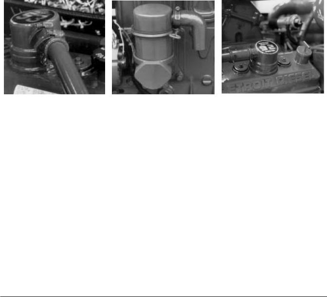
I-53 Fuel Filters |
I-71 Fuel Filters |
V-92 Fuel Filters |
V-71 Fuel Filters |
Figure 2
Page 15
SECTION 3.2 |
|
|
|
|
|
DDFP |
||
|
|
AIR INTAKE AND EXHAUST SYSTEM |
|
|
|
|||
AIR INTAKE OPERATION |
|
|
The air, entering the blower from the air cleaner , is picked |
|||||
|
|
|
|
|||||
In the scavenging process employed in the engines, a charge |
|
up by the blo wer rotor lobes and carried to the dischar |
|
ge |
||||
of air is forced into the c |
ylinders by the blo wer and thor- |
side of the blower as indicated by the arro ws in Figure 1 & |
||||||
oughly sweeps out all of |
the b |
urned gases through |
the |
2, Page 1. The continuous dischar ge of fresh air from the |
||||
exhaust v alves. This air |
also |
helps to cool the inter |
nalblower |
enters the air chamber of the c |
ylinder block |
and |
||
engine parts, particularly the e xhaust valves. At the be gin- |
sweeps through the intake ports of the cylinder liners. |
|
|
|||||
ning of the compression strok e, therefore, each cylinder is |
The angle of the ports in the c ylinder liners creates a uni- |
|||||||
filled with fresh, clean air which provides for efficient com- |
|
|||||||
bustion. |
|
|
|
form swirling motion to the intak e air as it enters the c ylin- |
||||
|
|
|
|
ders. |
This motion persists throughout |
the compr |
ession |
|
AIR CLEANER
The air cleaner used on DDFP engines is either a dry type or the reusable type. Should a situation occur where the air cleaner becomes plugged with dirt (starving the engine for air), low power and heavy black smoke will be the result; the air cleaner should be serviced immediately.
CAUTION: Do not attempt to remo ve the air cleaner while an engine is running nor run the engine while the air cleaner is of f. Exposed turbocharger could cause se vere injury to personnel and major internal engine damage could occur should an y foreign matter be dra wn into the engine.
1.On engines using dry elements, replace the air cleaner element.
2.On engines with pre-oiled elements, service with a special oil. These elements can be serviced or replaced. Part number is shown in the parts section of this manual.
3.When servicing the element is not practical, you can improve filter efficiency by re-spraying with oil.
NOTE: Do not attempt this while engine is running.
NOTE: Do not over oil.
Page 16

SECTION 3.2 |
DDFP |
AIR FILTER SERVICE INSTRUCTIONS
Figure 1 - Air Filter Service Instructions
Page 17
SECTION 3.2 |
DDFP |
AIR BOX DRAINS
During normal engine operation, water v apor from the intake air, as well as a slight amount of fuel and lubricating oil fumes, condenses and settles on the bottom of the air box. This condensation is remo ved by the air box pressure through air box drain tubes mounted on the side of the cylinder block.
Liquid accumulation in the air box will result if a drain tube becomes plugged. Remo ve the drain tubes and connectors from the c ylinder block and clean them thoroughly when necessary.
CRANKCASE VENTILATION
Harmful vapors which may form within the engine are removed from the crankcase, gear train, and injector compart-
ments by a continuous, pressurized ventilation system.
|
|
|
|
|
|
|
|
|
|
I-53 |
|
I-71 |
V71 or V-92 |
|
|
|
|
|
|
Figure 2 - Crankcase Ventilation
A slight pressure is maintained within the engine crankcase and injector compartment. This crankcase pressure and resulting ventilation is accomplished by the air seepage past the piston rings sweeping up through the flywheel housing and/or the balance weight co ver into the v alve and injector
rocker arm compartment. Here it is e xpelled through a vent pipe attached to the rock er cover breather assembly. Turbo charged I-71 engines additionally use a breather attached to the front left side of the c ylinder block. Figure 2 sho ws the vent system for each engine series.
Page 18

SECTION 3.2 |
|
|
|
DDFP |
|
EXHAUST OPERATION |
|
|
|
|
|
Internal combustion engines con vert fuel ener gy into both |
If the exhaust system should become restricted, the hot ex- |
||||
useful w ork and w asted heat. |
The useful w ork is the fly- |
haust gases cannot escape from the engine. |
This condition |
||
wheel rotation that dri ves |
the pump. |
The w asted heatwould cause a loss of po wer, extreme internal engine heat, |
|||
involves the engine water cooling system, radiated heat and |
and very high e xhaust gas temperatures. |
These conditions |
|||
the exhaust gases. Approximately2/3 of the fuel ener gy is |
can and will cause internal cylinder damage and a reduction |
||||
wasted. Critical re view must be made of these systems to |
of engine life. |
|
|
||
assure that the engine delivers the useful power required and |
|
|
|
||
maintains the engine within the operating parameters estab- |
|
|
|
||
lished by the engine manufacturer. |
|
|
|
|
|
The exhaust system is critical to the proper engine performance. When initially installed, consideration must be gi ven to the exhaust gas flow requirements, the exhaust temperatures and the e xhaust back-pressure limitations of the specific engine. Generally , N engines can tolerate a higher exhaust pressure than T engines. Refer to Section 5 for specific engine model and operating speed back-pressure limitations. All the components in an exhaust system contribute to the back-pressure determination including the fle exhaust section, muffler, exhaust piping and its conf iguration. In addition to providing engine exhaust data and backpressure limitations, Clarke of fers a service to installers, through the local Pump OEM Dealer , for making recommendations on e xhaust system sizing for specif ic installations.
MAINTENANCE AND SERVICE PROCEDURES
Weekly
Prior to each maintenance run mak e a visual check of the exhaust system to v erify condition of piping and muf fler (if used). Investigate thoroughly any areas that w ould appear to have rusty conditions such as rain w ater running do wn pipe and getting inside the engine. Se vere internal engine damage could occur.
Inspect the engine air cleaner for dirt b uildup or damage.
During actual maintenance run check engine crankcase ventilation tube for excessive blow-by or pressure.
6 Months
Inspect exhaust system for leaks or plugging,if any are found, repair immediately. Inspect and tighten if necessary e xhaust manifold, turbo mount (if equipped) and piping bolts/n uts. NFPA 37 requirements are to ha ve the e xhaust system co v- ered with high temperature insulation for personnel protection. Inspect the insulations condition for any deterioration or looseness, repair as necessary.
Exhaust system back pressure limits are not to be e xceeded.
NOTE: Exhaust back pressure, air inlet restriction and crankcase pressure limits are listed for each DDFP Model in Technical Data Section 5. These limits are not to be e xceeded. To properly check these limits, the engine must be producing maximum required horsepower.
While the engine is running inspect e xhaust pipe outlet outside of the pump room itself for en vironmental hazards such as excessive smoke conditions. The following could be used as a guide for general engine operating conditions.
1.Blue Smoke — Possible engine oil consumption - too many areas to list for possibilities.
2.White Smoke — Possibility of water in cylinders
Source — Possible w ater in fuel or internal engine prob-
lem.
Should any of these or any other conditions be found, contact your local DDC Distrib utor/Dealer for assistance. Check condition of the air inlet system ducting, clamp tightness hose condition.
Yearly
Clean and re-oil the air cleaner element per the manufacturers directions. Each engine is shipped with the cleaning instructions. Refer to Figure 1, page 17.
Check crankcase v entilation tube for proper operation by making a visual inspection while engine is running.
Page 19

SECTION 3.3 |
DDFP |
|
LUBRICATION SYSTEM |
OPERATION |
OIL COOLER |
The lubricating oil system is schematically illustrated in Figures 1, 2 and 3 for the Inline and VEE engines. The system consists of an oil pump, oil cooler, a full-flow oil filter, by-pass valves at the oil cooler and filter, and pressure regulator valves at the pump and in the c ylinder block main oil gallery. Positive lubrication is ensured at all times by this system.
Oil for lubricating the connecting rod bearings, piston pins,
and for cooling the piston head, |
is pro vided through the |
|
drilled hole in the crankshaft from |
the adjacent forw |
ard |
main bearings. The gear train is lubricated by the o verflow of the oil from the camshaft pock et through a connecting passage into the flywheel housing from the camshaft, balance shaft, and idler gear bearings. The blower drive gear bearing is lubricated through an e xternal pipe from the rear horizontal oil passage of the cylinder block.
On the Inline engines the oil from the cam pocket enters the blower and overflows through two holes, one at each end of the blo wer housing, providing lubrication for the blo wer drive gears at the rear end and for the go vernor mechanism at the front. On the VEE engines, the blower drive gear is lubricated from the rear of the blower.
All engines use a plate type oil cooler. Between each engine model, the major difference lies in the number of plates in each cooler. The number of plates required is determined by engine horsepo wer de veloped. All the oil cooler systems incorporate oil bypass valves in the event of plate core plugging.
It should be understood that improper engine maintenance could adversely effect the ef ficiency of the oil cooler system. Please refer to the technical data Section 5, for specific lube oil temperature and engine coolant temperature ranges for each engine model.
LUBE OIL FILL
On I-71 engines, the oil fill is located on the right rear . On the VEE engines, it is found in the right bank v alve rocker cover. On the 53 Series engine, the oil fill is also located on the rocker cover. See technical data, Section 5 for oil v olumes and specif ications on each engine model. A typical oil fill location is shown in Figure 5, Page 24.
LUBE OIL PUMP
The positive displacement gear type pump is mounted to the main bearing caps on I-71 and dri ven from the front end of the crankshaft. On the I-53,V-71 andV-92 engines the pump is found in the lower front cover and driven by the front end of the crankshaft. The I-71, V-71 and V-92 have a pressure
relief located on the dischar ge side of the pump, which maintains pressure being delivered to the oil filter and cool-
er. The I-53 engine does not use a pressure relief v alve but does incorporate the use of the f ilter and oil cooler bypass valve to maintain pressure.
All four engines use an oil pressure regulator valve to maintain oil g alley minimum pressures. See technical data Section 5 for specifics per engine model.
OIL LEVEL DIPSTICK
On most DDFP engines, the dipstick is located on the lower left side. Exceptions are the I-71 and 12V92 models where the dipstick is located on the right. Oil level can be checked only when the engine is at rest (not running). Oil levels must be maintained between the low and full marks.
NOTE: Due to the basic engine design, DDC engines retain large volumes of oil in the block while running. For this reason, proper oil level cannot be checked immediately after engine shut of f. Wait approximately 10 minutes before checking oil le vel. Do not add oil to a running engine; overfilling can occur!
Page 20
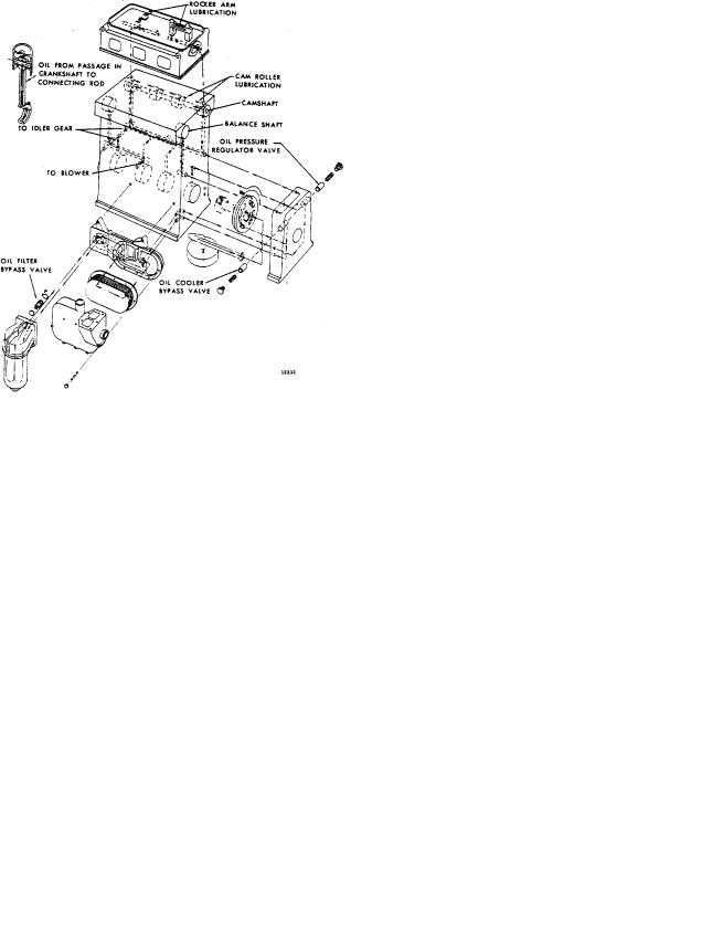
SECTION 3.3 |
|
|
DDFP |
|||
|
|
|
|
|
|
|
|
|
|
|
|
|
|
|
|
|
|
|
|
|
|
|
|
|
|
|
|
|
|
|
|
|
|
|
|
|
|
|
|
|
|
Fig. 1 - I-53 Lubricating System Schematic |
Fig. 2 - I-71 Lubricating System Schematic |
||||
|
|
|
|
|
|
|
|
|
|
|
|
|
|
|
|
|
|
|
|
|
|
|
|
Fig. 3 - V-71 & 92 Lubricating System Schematic
Page 21

SECTION 3.3 |
DDFP |
LUBE OIL FILTER
All engines use full flow oil filters of the "spin on" type element. They have a non-replaceable pleated paper cartridge. Each filter has an integral bypass valve in the event of plugging or for cold start purposes.
specify a Mil-L-2104F type oil. Because the y may display different viscosity grades, it is necessary to use a SAE 40 grade only.
TWO-CYCLE ENGINES
NOTE: Use only appro ved f ilters with the recommended filtration micron rating. See parts list Section 6 for proper service part numbers.
Replacing Spin on Oil Filter(s)
1.Obtain the Detroit Diesel recommended replacement lube oil filter. See Chart, Page 44.
2. Use a properly sized oil f ilter wrench, such Kentmoore P/N J24783, and remove filter(s).
3.Discard used filter(s) as recommended by EPA.
4.Clean the f ilter base mounting surf ace with a lint free cloth.
5.Lightly coat the oil filter seal with clean engine oil.
DETROIT DIESEL SERIES 53, 71, 92
LUBRICANT REQUIREMENTS
API Symbol:
|
|
|
* |
as |
|
|
SAE Viscosity Grade: 40 |
|
|
API Classification: CDII or CF2 |
|
|
|
|
|
|
|
|
Sulfated Ash: less than 1.0% |
|
*CF-2 when available |
||
|
|
||
This is the only oil recommended for Detroit Diesel Engines used in DDFP service. Lubricants meeting these criteria have provided maximum engine life when used in conjunction with recommended oil drain and f ilter maintenance schedules.
6. Start threading the ne w replacement f ilter onto the |
Certain engines operating conditions |
may require e xcep- |
|
threaded portion of the base and hand tighted until the |
tions to this recommendation. They are as follows: |
||
seal contacts the filter head. With the filter wrench, con- |
1. For continuous high temperature operation (o ver 100° F |
||
tinue to tighten two-thirds of a turn. |
|||
|
|
38° C Ambient), the use of SAE 50 grade lubricant in all |
|
7. Start engine and check for leaks. If any are found do not |
|
DDFP engines is recommended. |
|
put engine into service until corrections are made. |
2. |
The API Performance Cate gory CF2 represents an en- |
|
|
|||
|
|
hanced level of lubricant performance o ver CD-II cate- |
|
LUBRICATING OIL REQUIREMENTS |
|
gory which it replaces. Lubricants meeting this new per- |
|
|
|
formance level may not be readily available. During this |
|
Hundreds of commercial oils are mark eted today, but label- |
|
interim period oils labeled as API CD-II may be used. |
|
ing terminology differs among suppliers and can be confus- |
3. |
When the use of High Sulfur Diesel Fuel (greater than |
|
ing. Some mark eters may claim that their lubricant is suit- |
|||
able for all mak es of diesel engines and may list engine |
|
0.5% mass) is una voidable, the use of lubricants with |
|
makes and types, including Detroit Diesel, on their contain- |
|
higher Total Base Numbers (alkalinity) are recommend- |
|
ers. Such claims, by themselves, are insufficient as a method |
|
ed. Refer to Fig. 4 for minimum |
TBN numbers to be |
of lubricant selection for DDFP engines. |
|
used for normal service. |
|
The proper lubricating oil for all DDFP engines is selected, based on SAE Viscosity Grade and API (American Petroleum Institute) Service Designation. Both of these properties are displayed in the API Symbol, which is illustrated within the specif ic requirements. For DDFP engines,
the proper lubricant must also possess a sulfated ash content below 1.0% mass.
Lubricating oils for Non-T actical Military usage currently

SECTION 3.3 |
DDFP |
2). During and after weekly maintenance run, check o ver entire engine for signs of oil leaks. Repair immediately if found or call your authorized DDC Distributor/Dealer for service.
NOTE: If oil is observed coming from the air box drain tubes while running, review maintenance procedure on page 19.
Yearly
Stationary diesel engines collect condensation in the engine oil pan while at rest. When in use, lubricating oil undergoes deterioration from combustion by-products and contamination. For these reasons, regardless of the appearance of the oil, change oil and filter(s) annually.
CAUTION: Use only recommended lube oil and oil f ilters. Internal engine damage and/or excessive wear could occur using unauthorized materials.
LUBRICATING OIL ANALYSIS
Oil Analysis kits are available through the DDC Distributor Network for efficient monitoring of the lubricating oil in a DDFP engine. Refer to Parts Information Section 6 to order.
Oil Analysis consists of a series of laboratory tests conducted on the engines lubricant. Some tests sho w the condition of the engine and others show the condition of the lubricant. Refer to Fig. 4 for warning limits.
|
TWO CYCLE ENGINES ONLY |
|
|
|
ASTM |
Condition |
|
|
Designation |
Measured |
53, 71, 92 |
|
|
|
|
Pentane Insolubles |
D 893 |
Engine |
1.0 |
% Max. |
|
Combust. |
|
Carbon (Soot) Content, |
E-1131 |
Engine |
0.8 |
TGA Mass % Max. |
|
Combust. |
|
Viscosity at 40°C cS |
D 445 & D 2161 |
Engine & Oil |
40.0 |
% Max. Increase |
|
|
15.0 |
% Max. Decrease |
|
|
|
Total Base Number (TBN) |
|
|
|
Min. |
D 664 or D4739 |
Oil |
1.0 |
Min. |
D 2896 |
|
2.0 |
Water Content (dilution) |
D 95 |
Engine |
0.30 |
Vol. % Max. |
|
|
|
Flash Point °C |
|
Engine |
|
Reduction Max. |
D 92 |
Fuel Dil. |
20.0 |
Fuel Dilution Vol. % Max. |
* |
Engine |
2.5 |
Glycol Dilution |
D 2982 |
Engine |
1000 |
PPM Max. |
|
|
|
Iron Content |
** |
Engine |
150 |
PPM Fe Max. |
|
Wear |
|
Copper Content |
** |
Engine |
25 |
PPM Cu Max. |
|
Wear |
|
Sodium Content PPM NA |
** |
Engine |
50 |
Over Baseline Max. |
|
Coolant |
|
Boron Content PPM B |
** |
Engine |
20 |
Over Baseline Max. |
|
Coolant |
|
|
|
|
|
**Various Methods
**Elemental Analyses are conducted using either emission or atomic absorption spectroscop y. Neither method has an ASTM designation.
Fig. 4 - Oil Analysis Warning Limits
Page 23
 Loading...