


TM 5-4210-227-24&P-2
TECHNICAL MANUAL
ORGANIZATIONAL, DIRECT SUPPORT, AND GENERAL SUPPORT MAINTENANCE MANUAL (INCLUDING REPAIR PARTS AND
SPECIAL TOOLS LIST)
FOR
85' AERIAL LADDER FIRE FIGHTING TRUCK
NSN 4210-00-965-1254
HEADQUARTERS, DEPARTMENT OF THE ARMY
7 NOVEMBER 1986

COMPLETE MANUAL TABLE OF CONTENTS
Publication |
Section |
Section Title |
TM 5-4210-227-24&P-1 |
1 |
Introduction/Tabulated Data |
|
2 |
Chassis Assembly |
|
3 |
Pump Assembly |
|
4 |
Ladder Assembly |
|
5 |
Hydraulic System |
|
6 |
Electrical System |
|
7 |
Pneumatic System |
|
8 |
Ladder Calibration and Adjustments |
|
9 |
Illustrations |
TM 5-4210-227-24&P-2 |
|
General Information |
|
1 |
Engine (less major assemblies) |
|
2 |
Fuel System and Governors |
|
3 |
Air Intake Systems |
|
4 |
Lubrication System |
|
5 |
Cooling System |
|
6 |
Exhaust System |
|
7 |
Electrical Equipment, Instruments and |
|
|
Protective Systems (Sections 8 through |
|
|
11 not included) |
|
12 |
Special Equipment |
|
13 |
Operation |
|
14 |
Tune-up |
|
15 |
Preventive Maintenance, Troubleshooting |
|
|
and Storage |
TM 5-4210-227-24&P-3 |
1 |
General Information |
|
2 |
Description and Operation |
|
3 |
Preventive Maintenance |
|
4 |
General Overhaul Information |
|
5 |
Disassembly of Transmission |
|
6 |
Rebuild of Subassemblies |
|
7 |
Assembly of Transmission |
|
8 |
Wear Limits and Spring Data |
TM 5-4210-227-24&P-4 |
1 |
Allison Automatic Transmission HT 700 |
|
|
Series Parts Catalog |
|
2 |
Supplemental Parts Information |
TM 5-4210-227-24&P-5 |
1 |
Drive Line |
|
2 |
Front Axle |
|
3 |
Rear Axle |
|
4 |
Steering System |
|
5 |
Fuel System |
|
6 |
Brake System |
|
7 |
Electrical System |
|
8 |
Miscellaneous |
A

COMPLETE MANUAL TABLE OF CONTENTS
Publication |
Section |
Section Title |
TM 5-4210-227-24&P-5 |
9 |
General Information |
(continued) |
10 |
Installation Instructions |
|
11 |
Troubleshooting and Service |
TM 5-4210-227-24&P-7 |
|
General Information |
|
1 |
Engine (less major assemblies) |
|
2 |
Fuel System and Governors |
|
3 |
Air Intake System |
|
4 |
Lubricator System |
|
5 |
Cooling System |
|
6 |
Exhaust System |
|
7 |
Electrical Equipment, Instruments and |
|
|
Protective Systems |
|
8 |
Power Take-off and Torque Converter |
|
9 |
Transmissions (Sections 10 and 11 not |
|
|
included) |
|
12 |
Special Equipment |
|
13 |
Operation |
|
14 |
Tune-up |
|
15 |
Preventive Maintenance, Troubleshooting |
|
|
and Storage |
TM 5-4210-227-24&P-8 |
|
Parts List and Foldouts |
|
|
Tools and Equipment |
TM 5-4210-227-10 |
1 |
Introduction/Tabulated Data |
|
2 |
Operator's Instructions |
|
3 |
Operator Maintenance |
|
4 |
Illustrations |
|
5 |
Operator's Manual, Series 92 Engines |
|
6 |
Operator's Manual, Series V-71 Engines |
|
7 |
Built-in Parts Book for Detroit Diesel |
|
|
Engines |
|
8 |
Operator's Manual, Fire Apparatus Chassis |
B
FOREWORD
Descriptions, instructions and parts listing pertaining to the Model QWT 85 are discussed throughout this manual under the general headings Chassis, Pump and Ladder. Foldout illustrations and schematics are located at the rear of this volume. The foldout format is provided in order that illustrations and schematics may be referred to while the supporting text is being examined and studied.
A detailed description is given in the Introduction of each volume to assist the user in finding the information required to maintain the equipment.
∙Operator's Manual (TM 5-4210-227-10)
This manual is designed to provide the information necessary for a fire
fighter or mechanic to properly operate the truck, the pump and the ladder.
∙Maintenance Manual (TM 5-4210-227-24&P)
This manual is divided into 8 volumes and contains the information necessary
for an experienced mechanic to-maintain and repair all facets of the appa-
ratus. Each volume is individually indexed for ease of reference. This
manual contains all the information necessary to obtain assemblies and sub-
assemblies or individual parts, required to repair and maintain the fire
truck.
i/(ii blank)
TABULATED DATA
a)Fire Truck
|
Federal Stock Number: |
4210-00-965-1254 |
|
Manufacturer 's Serial No.: |
|
|
Registration Nos.: |
CM3653 through CM3664 |
|
Manufacturer: |
Pierre Thibault Inc. |
|
Model: |
QWT 85 |
|
Contract Number: |
DAAJ10-84-A218 |
|
Truck Length: |
459" |
|
Truck Width: |
108" |
|
Truck Height: |
138" |
|
Capacity or Payload: |
51,000 GVWR |
|
Shipping Weight: |
43,880 |
|
Ground Clearance: |
10.25" |
|
Weight Loaded: |
45,940 |
|
Front Axle |
19,740 |
|
Rear Axle |
26,200 |
b) |
Chassis |
|
|
Manufacturer: |
Duplex |
|
I.D. Number: |
I.C. lD91 D31 |
|
|
D6F 1008468 |
|
Model: |
D350 |
|
Wheel Base |
230" |
c) |
Engine |
|
|
Manufacturer: |
Detroit Diesel |
|
Model: |
8V-71 Turbo |
|
Serial Number: |
8VA437868 |
|
Fuel: |
Diesel |
iii
d) |
Transmission |
|
|
Manufacturer: |
Allison |
|
Model: |
HT-740 |
|
Serial No.: |
2510087501 |
|
Capacity: |
7 1/2 Gals |
e)Firefighting Water Pump
|
Manufacturer: |
Hale |
|
Model: |
QSM FHD100 |
|
Capacity: |
1000 GPM @ 150 psi |
f) |
Front Axle |
|
|
Manufacturer: |
Rockwell International |
|
Model: |
FL 941 QX-70 |
|
Capacity: |
20,000 lbs. |
|
Serial No.: |
N766718 |
f)1. Front Shock Absorbers
Manufacturer: |
Duplex |
Model: |
7605-1258 |
f)2. Front Springs
|
Manufacturer |
Duplex |
|
Model: |
7804-6731 |
g) |
Rear Axle |
|
|
Manufacturer: |
Rockwell International |
|
Model: |
U-170 PX-99 |
|
Capacity: |
31,000 lbs. |
|
Serial No.: |
NW845892 |
g)1. Rear Suspension
Manufacturer: |
Hendrickson |
Model: |
Single Axle RS-SA-340 |
iv
h ) |
Alternator |
|
|
Manufacturer: |
Delco Remy |
|
Model: |
|
|
Amp. |
145 |
i) |
Batteries |
|
|
Manufacturer: |
Harris |
|
Model: |
7605-0670 |
|
Voltage: |
12 |
j)Battery Isolator
Manufacturer: |
Sure Power |
Model: |
1602 |
Rated Power: |
3709 BHP @ 2,100 rpm |
k)Steering Gear
Manufacturer: |
Sheppard |
Model: |
7605-5478 |
1)Power Steering Pump
Manufacturer: |
Vickers |
Model: |
7605-5256 |
m)Windshield Wipers
Manufacturer: |
American Bosch |
Model: |
WWC-12L |
Type: |
Electric |
n)Radiator
|
Manufacturer: |
Blackstone |
|
Model: |
7605-3750 |
o) |
Air Cleaner |
|
|
Manufacturer: |
FAAR |
|
Model: |
62891-3 |
v
p)Driver's Seat
|
Manufacturer: |
Bostrom |
|
Model: |
Four-way Adjustable |
|
Type: |
Standard |
q) |
Wheels |
|
|
Front: |
|
|
Manufacturer: |
Firestone |
|
Size: |
22.5 x 16.5 |
|
Rear: |
|
|
Manufacturer: |
Firestone |
|
Size: |
20 x 8.5 |
r) |
Tires |
|
|
Front: |
|
|
Manufacturer: |
Goodyear |
|
Size: |
16.5 R 22.5 - 18 P.R. |
|
Capacity: |
20,000 lbs |
|
Rear: |
|
|
Manufacturer: |
Michelin |
|
Size: |
12:00 R 20X - 18 P.R. |
|
Capacity |
31,000 lbs. |
s) |
Muffler |
|
|
Manufacturer: |
Nelson |
|
Model: |
86130-21 |
t)AC Inverter
|
Manufacturer: |
Dynamote |
|
Model: |
A40-120 |
u) |
Siren/PA |
|
|
Manufacturer: |
Code 3 |
|
Model: |
3100 |
vi
CAPABILITIES
Fire Truck
Turning Radius - Inside 31.5' - Outside 42.25' Rated Power: 370 BHP @ 2,100 rpm
Engine Governor Setting: No Load - 2,100; Top Speed 58 mph
Acceleration: 0 - 35 mph - 14 Seconds Braking: 20 to 0 mph - 15 feet
Angle of Departure: Front - 15 degrees; Rear - 15 degrees
Pump
Single Stage Centrifugal Midship Mounted
Driven by the truck engine from the output shaft of transmission
Min discharge - 1000 gpm @ 150 psi Min discharge - 100 gpm @ 200 psi Min discharge - 500 gpm @ 250 psi
From dry condition - take suction and discharge water in 30 sec. with a lift of 10 deg. through 20' of 6" suction hose
12 VDC Priming Pump Water Tank - 200 gals.
Ladder
Basic Weight - 11,560 lbs., Outrigger Operation Speed
Lower: Front - 9 sec. Rear - 18 sec. Raise: Front - 9 sec. Rear - 18 sec.
Complete extension, elevation and 90 degrees rotation within 60 sec.
Hydraulic Tank: 45 gals. (Imp.)
vii
MAINTENANCE MANUAL
SECTION I
1. INTRODUCTION/TABULATED DATA
1.1INTRODUCTION
1.1.1.TM 5-4210-227-24&P, Organizational, Direct Support, and General Support Maintenance Manual for the 85' Aerial Ladder Fire Fighting Truck is divided into eight volumes. These eight volumes are further subdivided into specific sections consisting of both Government and commercial literature. TM 5-4210-227-10, Operator's Manual for the 85' Aerial Ladder Fire Fighting Truck is one separate manual consisting of four separate sections.
1.1.2.This volume consists of 12 sections and is arranged as follows: GENERAL INFORMATION
1.Engine (less major assemblies)
2.Fuel System and Governors
3.Air Intake Systems
4.Lubrication System
5.Cooling System
6.Exhaust System
7.Electrical Equipment, Instruments and Protective Systems
12.Special Equipment
13.Operation
14.Tune-Up
15.Preventive Maintenance, Troubleshooting and Storage
NOTE
For the Parts List for the 3V-71 Turbo Engine refer to duplex "Engine - Common-Parts" (on the following page) and "DETROIT DIESEL ENGINES - V71 OPERATORS' MANUAL," Section 8, "BUILT IN PARTS BOOK.1"
viii
IMPORTANT SAFETY NOTICE
Proper service and repair is important to the safe, reliable operation of all motor vehicles. The service procedures recommended by Detroit Diesel Allison and described in this service manual are effective methods for performing service operations. Some of these service operations require the use of tools specially designed for the purpose. The special tools should be used when and as recommended. It is important to note that some warnings against the use of specific service methods that can damage the vehicle or render it unsafe are stated in this service manual. It is also important to understand these warnings are not exhaustive. Detroit Diesel Allison could not possibly know, evaluate and advise the service trade of all conceivable ways in which service might be done or of the possible hazardous consequences of each way. Consequently, Detroit Diesel Allison has not undertaken any such broad evaluation. Accordingly, anyone who uses a service procedure or tool which is not recommended by Detroit Diesel Allison must first satisfy himself thoroughly that neither his safety nor vehicle safety will be jeopardized by the service method he selects.
6SE228 (Rev. 7/82)
Printed in U.S.A. |
c 1982 General Motors Corp. |
FOREWORD
This manual contains instructions on the overhaul, maintenance and operation of the basic V-71 Detroit Diesel Engines.
Full benefit of the long life and dependability built into these engines can be realized through proper operation and maintenance. Of equal importance is the use of proper procedures during engine overhaul.
Personnel responsible for engine operation and maintenance should study the sections of the manual pertaining to their particular duties. Similarly, before beginning a repair or overhaul job, the serviceman should read the manual carefully to familiarize himself with the parts or sub-assemblies of the engine with which he will be concerned.
The information, specifications and illustrations in this publication are based on the information in effect at the time of approval for printing. This publication is revised and reprinted periodically. It is recommended that users contact an authorized Detroit Diesel Service Outlet for information on the latest revisions. The right is reserved to make changes at any time without obligation.
TABLE OF CONTENTS |
|
SUBJECT |
|
GENERAL INFORMATION |
1 |
|
|
ENGINE (less major assemblies) |
|
|
2 |
FUEL SYSTEM AND GOVERNORS |
|
|
3 |
AIR INTAKE SYSTEM |
|
|
4 |
LUBRICATION SYSTEM |
|
|
5 |
COOLING SYSTEM |
|
|
6 |
EXHAUST SYSTEM |
|
|
7 |
ELECTRICAL EQUIPMENT, INSTRUMENTS AND PROTECTIVE SYSTEMS |
|
|
12 |
SPECIAL EQUIPMENT |
|
|
13 |
OPERATION |
|
|
14 |
TUNE-UP |
|
|
15 |
PREVENTIVE MAINTENANCE, TROUBLE SHOOTING AND STORAGE |
1980 General Motors Corporation |
Sept., 1980 |

General Information |
DETROIT DIESEL V-71 (Vehicle) |
SCOPE AND USE OF THE MANUAL
This manual covers the basic V-71 on-highway vehicle diesel engines built by the Detroit Diesel Allison Division of General Motors Corporation. Complete instructions on operation, adjustment (tune-up), preventive maintenance and lubrication, and repair (including complete overhaul) are covered. The manual was written primarily for persons servicing and overhauling the engine and, in addition, contains all of the instructions essential to the operators and users. Basic maintenance and overhaul procedures are common to all V-71 engines and therefore apply to all engine models.
The manual is divided into numbered sections. The first section covers the engine (less major assemblies). The following sections cover a complete system such as the fuel system, lubrication system or air system. Each section is divided into subsections which contain complete maintenance and operating instructions for a specific subassembly on the engine. For example, Section 1, which covers the basic engine, contains subsection 1.1 pertaining to the cylinder block, subsection 1.2 covering the cylinder head, etc. The subjects and sections are listed in the Table of Contents on the preceding page. Pages are numbered consecutively, starting with a new Page I at the beginning of each subsection. The illustrations are also numbered consecutively, beginning with a new Figure I at the start of each subsection.
Information regarding a general subject, such as the lubrication system, can best be located by using the Table of Contents. Opposite each subject in the Table of Contents is a section number which registers with a tab printed on the first page of each section throughout the manual. Information on a specific subassembly or accessory can then be found by consulting the list of contents on the first page of the section. For example, the cylinder liner is part of the basic engine, therefore, it will be found in Section 1. Looking down the list of contents on the first page of Section 1, the cylinder liner is found to be in subsection 1.6.3. An Alphabetical Index at the back of the manual has been provided as an additional aid for locating information.
SERVICE PARTS AVAILABILITY
Genuine Detroit Diesel Allison service parts are available in the United States from authorized distributors and service dealers throughout the world. A complete list of all distributors and dealers is available in the World Wide Parts and Service Directory, 6SE280. This publication can be ordered from any authorized distributor.
CLEARANCES AND TORQUE SPECIFICATIONS
Clearances of new parts and wear limits on used parts are listed in tabular form at the end of each section throughout the manual. It should be specifically noted that the "New Parts" clearances apply only when all new parts are used at the point where the various specifications apply. This also applies to references within the text of the manual. The column entitled "Limits" lists the amount of wear or increase in clearance which can be tolerated in used engine parts and still assure satisfactory performance. It should be emphasized that the figures given as "Limits" must be qualified by the judgment of personnel responsible for installing new parts. These wear limits are, in general, listed only for the parts more frequently replaced in engine overhaul work. For additional information, refer to the paragraph entitled Inspection under General Procedures in this section.
Bolt, nut and stud torque specifications are also listed in tabular form at the end of each section.
Page 4 |
© 1980 General Motors Corp. |

General Information |
DETROIT DIESEL V-71 (Vehicle) |
PRINCIPLES OF OPERATION
The diesel engine is an internal combustion power unit, in which the heat of fuel is converted into work in the cylinder of the engine.
In the diesel engine, air alone is compressed in the cylinder; then, after the air has been compressed, a charge of fuel is sprayed into the cylinder and ignition is accomplished by the heat of compression.
The Two-Cycle Principle
In the two-cycle engine, intake and exhaust take place during part of the compression and power strokes respectively as shown in Fig. 1. In contrast, a four cycle engine requires four piston strokes to complete an operating cycle; thus, during one half of its operation, the four-cycle engine functions merely as an air pump.
A blower is provided to force air into the cylinders for expelling the exhaust gases and to supply the cylinders with fresh air for combustion. The cylinder wall contains a row of ports which are above the piston when it is at the bottom of its stroke. These ports admit the air from the blower into the cylinder as soon as the rim of the piston uncovers the ports as shown in Fig. 1 (scavenging).
The unidirectional flow of air toward the exhaust valves produces a scavenging effect, leaving the cylinders full of clean air when the piston again covers the inlet ports.
As the piston continues on the upward stroke, the exhaust valves close and the charge of fresh air is subjected to compression as shown in Fig. 1 (compression).
Shortly before the piston reaches its highest position, the required amount of fuel is sprayed into the combustion chamber by the unit fuel injector as shown in Fig. 1 (power). The intense heat generated during the high compression of the air ignites the fine fuel spray immediately. The combustion continues until the fuel injected has been burned.
The resulting pressure forces the piston downward on its power stroke. The exhaust valves are again opened when the piston is about half way down, allowing the burned gases to escape into the exhaust manifold as shown in Fig. 1 (exhaust). Shortly thereafter, the downward moving piston uncovers the inlet ports and the cylinder is again swept with clean scavenging air. This entire combustion cycle is completed in each cylinder for each revolution of the crankshaft, or, in other words, in two strokes; hence, it is a "two-stroke cycle".
FIG. 1 - The Two-Stroke Cycle
Page 5 © 1976 General Motors Corp. June 1976

General Information |
DETROIT DIESEL V-71 (Vehicle) |
GENERAL DESCRIPTION
The two-cycle diesel engines covered in this manual are produced in 6, 8 and 12 cylinder models having the same bore and stroke and many of the major working parts such as injectors, pistons, connecting rods, cylinder liners and other parts that are interchangeable.
All cylinder blocks are symmetrical in design thus permitting oil cooler or starter installation on the same side or on opposite sides of the engine, depending upon the installation requirements. The engines are built with right-hand or lefthand crankshaft rotation. For example, the crankshaft in an RC engine, viewed from the flywheel end, will rotate counterclockwise, the oil cooler will be mounted on the right-hand side of the engine and the starter will be on the lefthand side (Fig. 2).
The meaning of each digit in the model numbering system is shown in Fig. 2. The letter L or R indicates left or righthand engine rotation as viewed from the front of the engine. The letter A, B, C or D designates the location of the starter and oil cooler as viewed from the rear of the engine.
Cylinder heads with either two valves or four valves per cylinder are used, as designated by the engine model.
Each engine is equipped with an oil cooler, lubricating oil filter, fuel oil strainer, fuel oil filter, air cleaner, governor, fan and radiator, and starting motor.
Full pressure lubrication is supplied to all main, connecting rod and camshaft bearings, and to other moving parts within the engine. A gear-type pump draws oil from the oil pan through an intake screen, through the oil filter and then to the oil cooler. From the oil cooler, the oil' flows through passages that connect with the oil galleries in the cylinder block and cylinder heads for distribution to the bearings, rocker arm mechanism and other functional parts.
Coolant is circulated through the engine by a centrifugal-type water pump. Heat is removed from the coolant, which circulates in a closed systern, by the radiator. Control of the engine temperature is accomplished by thermostats which regulate the flow of the coolant within the cooling system. Fuel is drawn from the supply tank through the fuel strainer by a gear-type fuel pump. It is then forced through a filter and into the fuel inlet manifolds in the cylinder heads and to the injectors. Excess fuel is returned to the supply tank through the fuel outlet manifolds and connecting lines. Since the fuel is constantly circulating through the injectors, it serves to cool the injectors and also carries off any air in the fuel system.
Air for scavenging and combustion is supplied by a blower which pumps air into the engine cylinders via the air box and cylinder liner ports. All air entering the blower first passes through an air cleaner. Engine starting is provided by an electric starting motor energized by a storage battery. A batterycharging generator, with a suitable voltage regulator, serves to keep the battery charged.
Engine speed is regulated by a mechanical governor.
Page 6 |
© 1976 General Motors Corp. |

General Information |
DETROIT DIESEL V-71 (Vehicle) |
FIG. 2 - Model Numbering, Rotation and Accessory Arrangement
Page 7 © 1980 General Motors Corp. SEPTEMBER 1980

General Information |
DETROIT DIESEL V-71 (Vehicle) |
FIG. 3 - V-71 Engine Cylinder Designation and Firing Order
GENERAL SPECIFICATIONS
|
6V |
8V |
12V |
Type ...................................................................................................... |
2 Cycle |
2 Cycle |
2 Cycle |
Number of Cylinders .............................................................................. |
6 |
8 |
12 |
Bore (inches) .......................................................................................... |
4.25 |
4.25 |
4.25 |
Bore (mm) ............................................................................................. |
108 |
108 |
108 |
Stroke (inches) ....................................................................................... |
5 |
5 |
5 |
Stroke (mm) ........................................................................................... .... |
127 |
127 |
127 |
Compression Ratio (Nominal) (Std. & Turbo. Engines) ......................... .... |
17 to 1 |
17 to 1 |
17 to 1 |
Compression Ratio (Nominal) ("N" Engines) .......................................... |
18.7 to 1 |
18.7 to 1 |
18.7 to 1 |
Total Displacement - cubic inches ................................... ...................... |
426 |
568 |
852 |
Total Displacement - litres ...................................................................... |
6.99 |
9.32 |
13.97 |
Number of Main Bearings ....................................................................... |
4 |
5 |
7 |
Page 8 |
© 1980 General Motors Corp. |
General Information |
DETROIT DIESEL V-71 (Vehicle) |
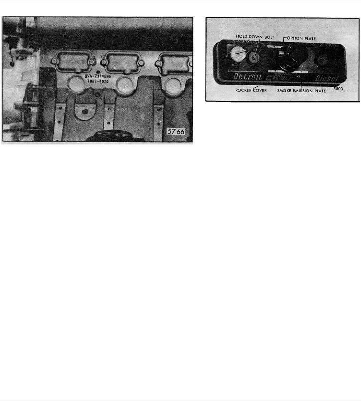
ENGINE MODEL, SERIAL NUMBER AND OPTION PLATE
FIG. 4 - Typical Engine Serial Number and
Model Number As Stamped on Cylinder Block
The engine serial number and the engine model number are stamped on the right rear side of the cylinder block (Fig. 4). This applies to former 6 and 8V-71 engines and current 12V-71 engines. To allow for easier engine serial number and model number identification on 6 and 8V-71 engines the location has been moved to the upper right front corner of the block.
NOTE: The 12V and 16V-71 engine identification will continue to be stamped at the former location, the right rear side of the cylinder block.
An option plate, attached to one of the valve rocker covers, is also stamped with the engine serial number and model number and. in addition, lists any optional
FIG. 5 - Option Plate
equipment used on the engine (Fig. 5).
An exhaust emission certification label. separate from the option plate. is mounted permanently in the option plate retainer. The current label includes information relating to an engine family for the maximum fuel injector size and maximum speed. Due to Federal regulations, the exhaust emission plate should not be removed. from the rocker cover. Refer to Section 14 for further information regarding emission regulations.
With any order for parts, the engine model number and serial number must be given. In addition, if a type number is shown on the option plate covering the equipment required, this number should also be included on the parts order.
All groups of parts used on an engine are standard for the engine model unless otherwise listed on the option plate.
Page 9 © 1980 General Motors Corp. SEPTEMBER 1980
General Information |
DETROIT DIESEL V-71 (Vehicle) |
GENERAL PROCEDURE
In many cases, a serviceman is justified in replacing parts with new material rather than attempting repair. However, there are times where a slight amount of reworking or reconditioning may save a customer considerable added expense. Crankshafts, cylinder liners and other parts are in this category. For example, if a cylinder liner is only slightly worn and within usable limits, a honing operation to remove the glaze may make it suitable for reuse, thereby saving the expense of a new part. Exchange assemblies such as injectors, fuel pumps, water pumps and blowers are also desirable service items.
Various factors such as the type of operation of the engine, hours in service and next overhaul period must be considered when determining whether new parts are installed or used parts are reconditioned to provide trouble-free operation.
For convenience and logical order in disassembly and assembly, the various subassemblies and other related parts mounted on the cylinder block will be treated as separate items in the various sections of the manual.
DISASSEMBLY
Before any major disassembly, the engine must be drained of lubricating oil, water and fuel. Lubricating oil should also be drained from any transmission attached to the engine.
To perform a major overhaul or other extensive repairs. the complete engine assembly, after removal from the vehicle and transmission, should be mounted on an engine overhaul stand; then the various subassemblies should be removed from the engine. When only a few items need replacement, it is not always necessary to mount the engine -on an overhaul stand.
Parts removed from an individual engine should be kept together so they will be available for inspection and assembly. Those items having machined faces, which might be easily damaged by steel or concrete, should be stored on suitable wooden racks or blocks, or a parts dolly.
CLEANING
Before removing any of the subassemblies from the engine (but after removal of the electrical equipment), the exterior of the engine should be thoroughly cleaned. Then, after each subassembly is removed and disassembled, the individual parts should be cleaned. Thorough cleaning of each part is absolutely necessary before it can be satisfactorily inspected. Various items of equipment needed for general cleaning are listed below.
The cleaning procedure used for all ordinary cast iron parts is outlined under Clean Cylinder Block in Section 1.1; any special cleaning procedures will be mentioned in the text wherever required.
Steam Cleaning
A steam cleaner is a necessary item in a large shop and is most useful for removing heavy accumulations of grease and dirt from the exterior of the engine and its subassemblies.
Solvent Tank Cleaning
A tank of sufficient size to accomodate the largest part that will require cleaning (usually the cylinder block) should be provided and provisions made for heating the cleaning solution to 180 °-200 0 F (82 °-93 °C).
Fill the tank with a commercial heavy-duty solvent which is heated to the above temperature. Lower large parts directly into the tank with a hoist. Place small parts in a wire mesh basket and lower them into the tank. Immerse the parts long enough to loosen all of the grease and dirt.
Rinsing Bath
Provide another tank of similar size containing hot water for rinsing the parts.
Drying
Parts may be dried with compressed air. The heat from the hot tanks will quite frequently complete the drying of the parts without the use of compressed air.
Page 10 © 1980 General Motors Corp. SEPTEMBER 1980

DETROIT DIESEL V-71 (Vehicle) |
General Information |
Rust Preventive
If parts are not to be used immediately after cleaning, dip them in a suitable rust preventive compound. The rust
preventive compound should be removed before installing the parts in an engine.
INSPECTION
The purpose of parts inspection is to determine which parts can be used and which must be replaced.
Although the engine overhaul specifications given throughout the text will aid in determining which parts should be replaced, considerable judgment must be exercised by the inspector.
The guiding factors in determining the usability of worn parts, which are otherwise in good condition, is the clearance between the mating parts and the rate of wear on each of the parts. If it is determined that the rate of wear will maintain the clearances within the specified maximum allowable until the next overhaul period, the reinstallation of used parts may be justified. Rate of wear of a part is determined by dividing the amount the part has worn by the hours it has operated.
Many service replacement parts are available in various undersize and/or oversize as well as standard sizes. Also, service kits for reconditioning certain parts and service sets which include all of the parts necessary to complete a particular repair job are available.
A complete discussion of the proper methods of precision measuring and inspection are outside the scope of this manual. However, every shop should be equipped with standard gages, such as dial bore gages, dial indicators, and inside and outside micrometers.
In addition to measuring the used parts after cleaning, the parts should be carefully inspected for cracks, scoring, chipping and other defects. Following cleaning and inspection, the engine should be assembled using new parts as determined by the inspection.
ASSEMBLY
Following cleaning and inspection, the engine should be assembled using new parts as determined by the inspection.
Use of the proper equipment and tools makes the job progress faster and produces better results. Likewise, a suitable working space with proper lighting must be provided. The time and money invested in providing the proper tools, equipment and space will be repaid many times.
Keep the working space, the equipment, tools and engine assemblies and parts clean at all times. The area where assembly operations take place should, if possible, be located away from the disassembly and cleaning operation. Also, any machining operations should be removed as far as possible from the assembly area.
Particular attention should be paid to storing of parts and sub-assemblies, after removal and cleaning and prior to assembly, in such a place or manner as to keep them clean. If there is any doubt as to the cleanliness of such parts, they should be recleaned.
When assembling an engine or any part thereof, refer to the table of torque specifications at the end of each section for proper bolt, nut and stud torques.
To ensure a clean engine at time of rebuild, it is important that any plug, fitting or fastener (including studs) that intersects with a through hole and comes in contact with oil, fuel or coolant must have a sealer
applied to the threads. A number of universal sealers are commercially available. It is recommended that Loctite J 26558-92 pipe sealer with teflon, or equivalent, be used.
NOTE: Certain plugs, fittings and fastener available from the Parts Depot already have a sealer applied to the threads. This pre-coating will not be affected when the pipe sealer with teflon is also applied.
IMPORTANT: The sealer information above must not be confused with International Compound No. 2, which is a lubricant applied before tightening certain bolts. Use International Compound No. 2 only where specifically stated in the manual.
© 1978 General Motors Corp. |
October, 1978 |
Page 11

DETROIT DIESEL V-71 (Vehicle) |
General Information |
WORK SAFELY
A serviceman can be severely injured if caught in the pulleys, belts or fan of an engine that is accidentally started. To avoid such a misfortune, take these precautions before starting to work on an engine:
Disconnect the battery from the starting system by removing one or both of the battery cables. With the electrical circuit disrupted, accidental contact with the
Some Safety Precautions To Observe When Working
On The Engine
1.Consider the hazards of the job and wear protective gear such as safety glasses, safety shoes, hard hat, etc. to provide adequate protection.
2.When lifting an engine, make sure the lifting device is fastened securely. Be sure the item to be lifted does not exceed the capacity of the lifting device.
3.Always use caution when using power tools.
4.When using compressed air to clean a component, such as flushing a radiator or cleaning an air cleaner element, use a safe amount of air. Recommendations regarding the use of air are indicated throughout the manual. Too much air can rupture or in some other way damage a component and create a hazardous situation that can lead to personal injury.
5.Avoid the use of carbon tetrachloride as a cleaning
starter button will not produce an engine start.
Make sure the mechanism provided at the governor for stopping the engine is in the stop position. This will mean the governor is in the no-fuel position. The possibility of the engine firing by accidentally turning the fan or by being bumped by another vehicle is minimized.
agent because of the harmful vapors that it releases. Use perchlorethylene or trichlorethylene. However, while less toxic than other chlorinated solvents, use these cleaning agents with caution. Be sure the work area is adequately ventilated and use protective gloves, goggles or face shield and an apron. Exercise caution against burns when using oxalic acid to clean the cooling passages of the engine.
6.Use caution when welding on or near the fuel tank. Possible explosion could result if heat build-up inside the tank is sufficient.
7.Avoid excessive injection of ether into the engine during start attempts. Follow the instructions on the container or by the manufacturer of the starting aid.
8.When working on an engine that is running, accidental contact with the hot exhaust manifold can cause severe burns. Remain alert to the location of the rotating fan, pulleys and belts. Avoid making contact across the two terminals of a battery which can result in severe arcing.
© 1978 General Motors Corp.
Page 12

DETROIT DIESEL V-71 (Vehicle) |
General Information |
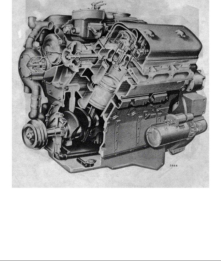
Three-Quarter Cutaway View of V-71 Engine (Dry Block)
© 1978 General Motors Corp. |
October, 1978 |
Page 13
DETROIT DIESEL V-71 (Vehicle) |
General Information |
Three-Quarter Cutaway View of V-71 engine (Water-Below-Port Block)
© 1978 General Motors Corp. |
October, 1978 |
Page 14

DETROIT DIESEL V-71 (Vehicle) |
General Information |
© 1978 General Motors Corp. |
October, 1978 |
Page 15

DETROIT DIESEL V-71 (Vehicle) |
1 |
SECTION 1 |
|
ENGINE (less major assemblies) |
|
CONTENTS |
|
Cylinder Block......................................................................................... |
1.1 |
Cylinder Block End Plates . ..................................................................... |
1.1.1 |
Air Box Drains ........................................................................................ |
1.1.2 |
Cylinder Head ......................................................................................... |
1.2 |
Valve and Injector Operating Mechanism ................................................ |
1.2.1 |
Exhaust Valves .. .................................................................................... |
1.2.2 |
Valve Rocker Cover ................................................................................ |
1.2.4 |
Crankshaft .............................................................................................. |
1.3 |
Crankshaft Oil Seals ............................................................................... |
1.3.2 |
Crankshaft Main Bearings . ..................................................................... |
1.3.4 |
Engine Front Cover (Lower) .................................................................... |
1.3.5 |
Crankshaft Vibration Damper .................................................................. |
1.3.6 |
Crankshaft Pulley.................................................................................... |
1.3.7 |
Flywheel ................................................................................................. |
1.4 |
Clutch Pilot Bearing .. ............................................................................. |
1.4.1 |
Flywheel Housing ................................................................................... |
1.5 |
Piston and Piston Rings .. ....................................................................... |
1.6 |
Connecting Rod .. ................................................................................... |
1.6.1 |
Connecting Rod Bearings ....................................................................... |
1.6.2 |
Cylinder Liner.......................................................................................... |
1.6.3 |
Engine Balance and Balance Weights..................................................... |
1.7 |
Gear Train and Engine Timing .. ............................................................. |
1.7.1 |
Camshafts and Bearings ......................................................................... |
1.7.2 |
Camshaft Gears ..................................................................................... |
1.7.3 |
Idler Gear and Bearing Assembly ........................................................... |
1.7.4 |
Crankshaft Timing Gear .......................................................................... |
1.7.5 |
Blower Drive Gear and Support Assembly............................................... |
1.7.6 |
Accessory Drives .. ................................................................................. |
1.7.7 |
Balance Weight Cover .. ......................................................................... |
1.7.8 |
Shop Notes - Trouble Shooting - Specifications - Service Tools .............. |
1.0 |
© 1974 General Motors Corp. |
September, 1974 SEC 1 |
Page 1
DETROIT DIESEL V-71 (Vehicle) |
1.1 |
CYLINDER BLOCK
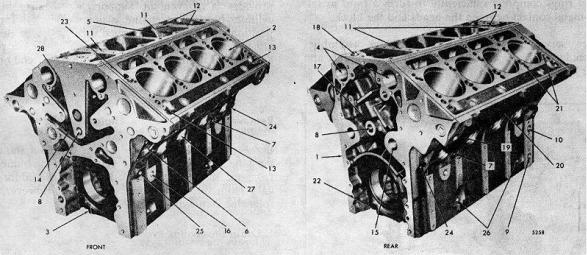
The cylinder block (Fig. 1) serves as the main structural part of the engine. Transverse webs provide rigidity and strength and ensure alignment of the block bores and bearings under load.
The block is bored to receive replaceable cylinder liners. The current cylinder block is designated as a water-below- port block and is designed to provide water cooling below the air inlet port belt. The former cylinder block was designated as a dry block.
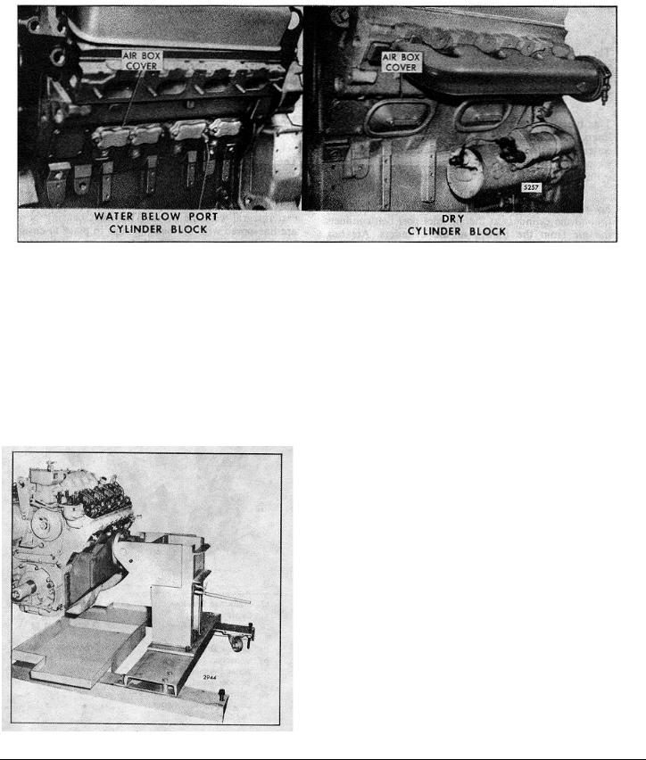
An air box between the cylinder banks and extending around the cylinders at the air inlet port belt conducts the air from the blower to the cylinders. Air box openings on each side of the block permit inspection of the pistons and compression rings through the air inlet ports in the cylinder liners. The air box openings in the current cylinder block assembly are approximately 1 7/8" x 3 1/8" and are covered with cast covers (Fig. 2). The stamped steel covers used on the former cylinder block covered openings which were approximately 3" x 6 1/2". To prevent leakage at the air box covers, new gaskets and
bolts are now being used. The new polyacrylic and cork gaskets replace the former asbestos gaskets. The
new lock and seal coated bolt replaces a stud, nut, flat washer and lock washer. The former and new gaskets are interchangeable on an engine, but only the new gaskets are serviced.
The camshaft bores are located on the inner side of each cylinder bank near the top of the block.
The upper halves of the main bearing supports are cast integral with the block. The main bearing bores are linebored with the bearing caps in place to ensure longitudinal alignment. Drilled passages in the block carry the lubricating oil to all moving parts of the engine, eliminating the need for external piping.
The top surface of each cylinder bank is grooved to accommodate a block-to-head oil seal ring. Also, each water or oil hole is counterbored to provide for individual seal rings.
1. |
Cylinder Block |
11. |
Oil Drain Passages to |
17. |
Crankcase Breather |
24. |
Oil Gallery |
||
2. |
Bore for Cylinder Liner |
|
Blower |
|
Cavity |
25. |
Oil Gallery |
||
3. |
Front Main Bearing Cap |
12. |
Oil Drain Passages |
18. |
Crankcase Breather |
26. |
Dipstick Hole or Oil |
||
4. |
Bores for Camshafts |
|
from Blower |
|
Outlet |
|
Return Passage to |
||
5. |
Air Box |
13. |
Oil Drain from Cylinder |
19. |
Air Box Drain |
|
Crankcase |
||
6. |
Water into Block |
|
Head |
20. |
Inspection Hole |
27. |
Core Hole for Water |
||
|
|
|
|
|
|
Opening |
|
Jacket |
|
7. |
Water Drain |
14. |
Oil Drain Passages |
21. |
Water Passages to |
28. |
Oil Tube |
||
8. |
Main Oil Gallery |
15. |
Oil Passage (Idler Gear |
|
Cylinder Head |
|
|
|
|
9. |
Oil Passage from Pump |
|
Bearing) |
22. |
Rear Main Bearing Cap |
|
|
|
|
|
to Oil Filter |
16. |
Oil Return Passages to |
23. |
Oil Passage to Cylinder |
|
|
|
|
10. |
Oil Passage from Oil |
|
Crankcase |
|
Head |
|
|
|
|
|
|
Cooler |
|
|
|
|
|
|
|
|
|
|
|
FIG. 1 - Cylinder Block (8V Engine) |
|
|
|
||
|
© 1980 General Motors Corp. |
|
Page 1 |
|
September, 1980 SEC 1.1 |
||||
|
|
|
|
|
|
|
|
||
DETROIT DIESEL V-71 (Vehicle) |
1.1 Cylinder Block |
FIG. 2 Comparison of Current and former Cylinder Blocks
Each cylinder liner is retained in the block by a flange at its upper end. The liner flange rests on an insert located in the counterbore in the block bore. An individual compression gasket is used at each cylinder.
When the cylinder heads are installed, the gaskets and seal rings compress sufficiently to form a tight metal-to- metal contact between the heads and the block.
New service replacement cylinder block assemblies include the main bearing caps and bolts, dowels and the
FIG. 3 Engine Mounted on Overhaul Stand
necessary plugs. Since the cylinder block is the main structural part of the engine, the various subassemblies must be removed from the cylinder block when an engine is overhauled.
The hydraulically operated overhaul stand (Fig. 3) provides a convenient support when stripping a cylinder block. The engine is mounted in an upright position. It may then be tipped on its side, rotated in either direction 90°or 180°where it is locked in place and then, if desired, tipped back with either end or the oil pan side up.
Remove and Disassemble Engine
Before mounting an engine on an overhaul stand, it must be removed from the vehicle and disconnected from the transmission. Details of this procedure will vary from one application to another. However, the following steps will be necessary.
1.Drain the cooling system.
2.Drain the lubricating oil.
3.Disconnect the fuel lines.
4.Remove the air cleaner and mounting brackets.
5.Remove the turbocharger, if used.
6.Disconnect the exhaust piping and remove the exhaust manifolds.
7.Disconnect the throttle controls.
© 1980 General Motors Corp.
Page 2
 Loading...