


EPA07/10 DD PLATFORM WORKSHOP MANUAL - ENGINE
TABLE OF CONTENTS
1 ROCKER COVER
1.1DESCRIPTION AND OPERATION OF ROCKER COVER AND RELATED
|
PARTS ...................................................................................................... |
1-3 |
1.2 |
REMOVAL OF THE ROCKER COVER .................................................... |
1-4 |
1.3 |
CLEANING AND INSPECTION OF THE ROCKER COVER ................... |
1-6 |
1.4 |
INSTALLATION OF THE ROCKER COVER ............................................ |
1-7 |
2 CAMSHAFT AND ROCKER SHAFT/ENGINE BRAKE ASSEMBLY
2.1DESCRIPTION AND OPERATION OF CAMSHAFT AND ROCKER
SHAFT/ENGINE BRAKE ASSEMBLY AND RELATED PARTS ............... |
2-3 |
2.2REMOVAL OF CAMSHAFT AND ROCKER SHAFT/ENGINE BRAKE
ASSEMBLY .............................................................................................. |
2-7 |
2.3INSPECTION OF THE CAMSHAFT AND ROCKER SHAFT/ENGINE
BRAKE ASSEMBLY ................................................................................. |
2-15 |
2.4INSTALLATION OF THE CAMSHAFT AND ROCKER SHAFT/ENGINE
BRAKE ASSEMBLY ................................................................................. |
2-16 |
2.5DD13 EGR COOLER CLEANING PROCEDURE TO REMOVE EXCESS
FUEL FROM COOLER AFTER ENGINE BRAKE SOLENOID FAILURE 2-26
2.6DD15 EGR COOLER CLEANING PROCEDURE TO REMOVE EXCESS
|
FUEL FROM COOLER AFTER ENGINE BRAKE SOLENOID FAILURE |
2-31 |
3 |
CAMSHAFT HOUSING |
|
3.1 |
REMOVAL OF THE CAMSHAFT HOUSING ........................................... |
3-3 |
3.2 |
INSPECTION OF CAMSHAFT HOUSING ............................................... |
3-8 |
3.3 |
INSTALLATION OF THE CAMSHAFT HOUSING ................................... |
3-9 |
4 |
CAMSHAFT TIMING |
|
4.1 |
CAMSHAFT TIMING VERIFICATION ...................................................... |
4-3 |
4.2 |
TIMING THE CAMSHAFTS WITH THE GEAR TRAIN INSTALLED ........ |
4-6 |
5 GEAR TRAIN AND ENGINE TIMING
5.1DESCRIPTION AND OPERATION OF GEAR TRAIN AND RELATED
PARTS ...................................................................................................... |
5-3 |
5.2 ENGINE GEAR TRAIN INSTALLATION AND TIMING ............................ |
5-8 |
5.3CHECKING AND ADJUSTING GEAR LASH WITH CAMSHAFT
HOUSING REMOVED ............................................................................. |
5-16 |
6 WATER MANIFOLD
6.1DESCRIPTION AND OPERATION OF DD15 & DD16 WATER
MANIFOLD AND RELATED COMPONENTS .......................................... |
6-3 |
6.2 REMOVAL OF THE DD15 & DD16 WATER MANIFOLD ......................... |
6-5 |
6.3CLEANING AND INSPECTION OF THE DD15 & DD16 WATER
MANIFOLD ............................................................................................... |
6-7 |
6.4 INSTALLATION OF THE DD15 & DD16 WATER MANIFOLD ................. |
6-8 |
All information subject to change without notice. |
i |
DDC-SVC-MAN-0081 2010 Copyright © 2010 DETROIT DIESEL CORPORATION |

EPA07/10 DD PLATFORM WORKSHOP MANUAL - ENGINE
6.5DD13 EXHAUST GAS RECIRCULATION COOLER WATER MANIFOLD
ASSEMBLY .............................................................................................. |
6-10 |
7 COLD BOOST PIPE (CHARGE AIR PIPE)
7.1DESCRIPTION AND OPERATION OF COLD BOOST PIPE (CHARGE
|
AIR PIPE) AND RELATED COMPONENTS ............................................ |
7-3 |
7.2 |
REMOVAL OF THE COLD BOOST PIPE (CHARGE AIR PIPE) ............. |
7-4 |
7.3 |
INSPECTION OF COLD BOOST PIPE (CHARGE AIR PIPE) ................ |
7-5 |
7.4 |
INSTALLATION OF THE COLD BOOST PIPE (CHARGE AIR PIPE) .... |
7-6 |
8 AIR INTAKE MANIFOLD
8.1DESCRIPTION AND OPERATION OF AIR INTAKE MANIFOLD AND
|
RELATED PARTS .................................................................................... |
8-3 |
8.2 |
REMOVAL OF AIR INTAKE MANIFOLD .................................................. |
8-6 |
8.3 |
CLEANING OF THE AIR INTAKE MANIFOLD ........................................ |
8-7 |
8.4 |
INSPECTION OF THE AIR INTAKE MANIFOLD ..................................... |
8-8 |
8.5 |
INSTALLATION OF AIR INTAKE MANIFOLD .......................................... |
8-9 |
9 DD13 TURBOCHARGER
9.1DESCRIPTION AND OPERATION OF THE DD13 TURBOCHARGER
|
AND RELATED PARTS ............................................................................ |
9-3 |
9.2 |
REMOVAL OF THE DD13 TURBOCHARGER ........................................ |
9-5 |
9.3 |
INSPECTION OF THE DD13 TURBOCHARGER ................................... |
9-9 |
9.4 |
INSTALLATION OF THE DD13 TURBOCHARGER ................................ |
9-10 |
9.5EGR COOLER CLEANING PROCEDURE TO REMOVE EXCESS FUEL
FROM COOLER AFTER DD13 TURBOCHARGER FAILURE ................ |
9-12 |
10 DD13 WASTEGATE SOLENOID
10.1DESCRIPTION AND OPERATION OF THE DD13 WASTEGATE
|
SOLENOID ............................................................................................... |
10-3 |
10.2 |
REMOVAL OF THE DD13 WASTEGATE SOLENOID ............................. |
10-4 |
10.3 |
INSTALLATION OF THE DD13 WASTEGATE SOLENOID ..................... |
10-6 |
11 DD15 TURBOCHARGER
11.1DESCRIPTION AND OPERATION OF TURBOCHARGER AND
|
RELATED PARTS .................................................................................... |
11-3 |
11.2 |
REMOVAL OF DD15 TURBOCHARGER ................................................ |
11-5 |
11.3 |
INSPECTION OF DD15 TURBOCHARGER ........................................... |
11-7 |
11.4 |
INSTALLATION OF DD15 TURBOCHARGER ........................................ |
11-8 |
11.5EGR COOLER CLEANING PROCEDURE TO REMOVE EXCESS OIL
FROM EGR COOLER AFTER DD15 TURBOCHARGER FAILURE ....... |
11-10 |
12 DD15 AXIAL POWER TURBINE
12.1DESCRIPTION AND OPERATION OF DD15 AXIAL POWER TURBINE
|
AND RELATED PARTS ............................................................................ |
12-3 |
12.2 |
REMOVAL OF DD15 AXIAL POWER TURBINE ..................................... |
12-5 |
12.3 |
INSPECTION OF THE DD15 AXIAL POWER TURBINE ........................ |
12-6 |
12.4 |
INSTALLATION OF DD15 AXIAL POWER TURBINE ............................. |
12-7 |
ii |
All information subject to change without notice. |
DDC-SVC-MAN-0081 2010 Copyright © 2010 DETROIT DIESEL CORPORATION |

EPA07/10 DD PLATFORM WORKSHOP MANUAL - ENGINE
13 DD15 AXIAL POWER TURBINE GEAR BOX
13.1DESCRIPTION AND OPERATION OF DD15 AXIAL POWER TURBINE
|
GEAR BOX AND RELATED PARTS ........................................................ |
13-3 |
13.2 |
REMOVAL OF THE DD15 AXIAL POWER TURBINE GEAR BOX ......... |
13-5 |
13.3 |
INSPECTION OF DD15 AXIAL POWER TURBINE GEAR BOX ............. |
13-6 |
13.4 |
INSTALLATION OF THE AXIAL POWER TURBINE GEAR BOX ............ |
13-7 |
14 CYLINDER HEAD
14.1DESCRIPTION AND OPERATION OF CYLINDER HEAD AND RELATED
|
PARTS ...................................................................................................... |
14-3 |
14.2 |
REMOVAL OF THE DD13 CYLINDER HEAD ......................................... |
14-10 |
14.3 |
INSTALLATION OF THE DD13 CYLINDER HEAD .................................. |
14-12 |
14.4 |
REMOVAL OF THE DD15 CYLINDER HEAD ......................................... |
14-15 |
14.5 |
CLEANING OF THE CYLINDER HEAD .................................................. |
14-17 |
14.6 |
ASSEMBLY OF CYLINDER HEAD .......................................................... |
14-18 |
14.7 |
INSTALLATION OF THE DD15 CYLINDER HEAD .................................. |
14-19 |
14.8 |
REMOVAL OF VALVE SPRING (CYLINDER HEAD INSTALLED) .......... |
14-22 |
14.9 |
REMOVAL OF THE VALVE SPRING (CYLINDER HEAD REMOVED) ... |
14-24 |
14.10 |
REMOVAL OF INTAKE AND EXHAUST VALVES ................................... |
14-25 |
14.11 |
CLEANING OF VALVES AND RELATED PARTS .................................... |
14-26 |
14.12 |
INSPECTION OF VALVE SPRINGS ........................................................ |
14-27 |
14.13 |
INSPECTION OF VALVE ......................................................................... |
14-28 |
14.14 |
INSTALLATION OF VALVE, SPRING, SEAL AND VALVE CAP .............. |
14-29 |
14.15 |
VALVE LASH ADJUSTMENTS ................................................................ |
14-31 |
14.16 |
SETTING THE ENGINE BRAKE LASH ................................................... |
14-33 |
15 PISTON AND CONNECTING ROD ASSEMBLY
15.1DESCRIPTION AND OPERATION OF PISTON AND CONNECTING
|
ROD AND RELATED PARTS ................................................................... |
15-3 |
15.2 |
REMOVAL OF PISTON AND CONNECTING ROD ASSEMBLY ............. |
15-5 |
15.3 |
DISASSEMBLY OF PISTON AND CONNECTING ROD ASSEMBLY ..... |
15-7 |
15.4 |
INSPECTION OF PISTON AND CONNECTING ROD ASSEMBLY ........ |
15-8 |
15.5 |
ASSEMBLY OF PISTON AND CONNECTING ROD ASSEMBLY ........... |
15-9 |
15.6 |
INSTALLATION OF PISTON AND CONNECTING ROD ASSEMBLY ..... |
15-11 |
16 CYLINDER LINER
16.1DESCRIPTION AND OPERATION OF CYLINDER LINER AND
|
RELATED PARTS .................................................................................... |
16-3 |
16.2 |
REMOVAL OF CYLINDER LINER ........................................................... |
16-4 |
16.3 |
INSPECTION OF CYLINDER LINER ...................................................... |
16-5 |
16.4 |
CLEANING OF THE CYLINDER LINER .................................................. |
16-7 |
16.5 |
INSTALLATION OF THE CYLINDER LINER ........................................... |
16-8 |
17 CRANKSHAFT
17.1DESCRIPTION AND OPERATION OF CRANKSHAFT AND RELATED
|
PARTS ...................................................................................................... |
17-3 |
17.2 |
REMOVAL OF CRANKSHAFT ................................................................. |
17-6 |
17.3 |
INSPECTION OF THE CRANKSHAFT AND RELATED PARTS ............. |
17-9 |
17.4 |
INSTALLATION OF CRANKSHAFT ......................................................... |
17-10 |
|
|
|
All information subject to change without notice. |
iii |
|
DDC-SVC-MAN-0081 2010 Copyright © 2010 DETROIT DIESEL CORPORATION |
||

EPA07/10 DD PLATFORM WORKSHOP MANUAL - ENGINE
17.5 |
REMOVAL OF CRANKSHAFT REAR OIL SEAL ..................................... |
17-14 |
17.6 |
INSTALLATION OF THE REAR OIL SEAL .............................................. |
17-15 |
17.7 |
REMOVAL OF THE CRANKSHAFT FRONT OIL SEAL .......................... |
17-17 |
17.8 |
INSTALLATION OF THE CRANKSHAFT FRONT OIL SEAL .................. |
17-18 |
18 LUBRICATION SYSTEM
18.1DESCRIPTION AND OPERATION OF THE LUBRICATION SYSTEM
AND RELATED COMPONENTS .............................................................. |
18-3 |
19 OIL PAN
19.1DESCRIPTION AND OPERATION OF OIL PAN AND RELATED
|
COMPONENTS ....................................................................................... |
19-3 |
19.2 |
REMOVAL OF OIL PAN ........................................................................... |
19-4 |
19.3 |
CLEANING OF OIL PAN .......................................................................... |
19-5 |
19.4 |
INSPECTION OF OIL PAN ...................................................................... |
19-6 |
19.5 |
REMOVAL OF THREADED INSERT — PLASTIC OIL PAN ONLY ......... |
19-7 |
19.6INSTALLATION OF THREADED INSERT — PLASTIC OIL PAN ONLY . 19-8
19.7 INSTALLATION OF OIL PAN ................................................................... |
19-9 |
20 OIL DIPSTICK TUBE
20.1DESCRIPTION AND OPERATION OF OIL DIPSTICK TUBE AND
|
RELATED COMPONENTS ...................................................................... |
20-3 |
20.2 |
REMOVAL OF THE OIL DIPSTICK TUBE ............................................... |
20-4 |
20.3 |
INSTALLATION OF THE OIL DIPSTICK TUBE ....................................... |
20-5 |
21 OIL PUMP
21.1DESCRIPTION AND OPERATION OF OIL PUMP AND RELATED
COMPONENTS ....................................................................................... |
21-3 |
21.2REMOVAL OF THE OIL PUMP, OIL SUCTION MANIFOLD, AND OIL
LINES ....................................................................................................... |
21-4 |
21.3INSPECTION OF THE OIL PUMP, OIL SUCTION MANIFOLD, AND OIL
LINES ....................................................................................................... |
21-5 |
21.4INSTALLATION OF THE OIL PUMP, OIL SUCTION MANIFOLD, AND
|
OIL LINES ................................................................................................ |
21-6 |
22 |
CRANKCASE BREATHER |
|
22.1 |
DESCRIPTION AND OPERATION OF CRANKCASE BREATHER ........ |
22-3 |
22.2 |
REMOVAL OF THE CRANKCASE BREATHER ...................................... |
22-5 |
22.3 |
INSPECTION OF THE CRANKCASE BREATHER ................................. |
22-6 |
22.4 |
INSTALLATION OF THE CRANKCASE BREATHER .............................. |
22-7 |
23 |
OIL FILTER |
|
23.1 |
REPLACEMENT OF THE OIL FILTER .................................................... |
23-3 |
24 |
OIL SAMPLE VALVE |
|
24.1 |
REPLACING OIL PLUG WITH OIL SAMPLE VALVE .............................. |
24-3 |
24.2 |
REMOVAL OF OIL SAMPLE VALVE ....................................................... |
24-4 |
24.3 |
INSTALLATION OF OIL SAMPLE VALVE ................................................ |
24-5 |
25 |
OIL FILLER NECK |
|
25.1 |
REMOVAL OF THE OIL FILLER NECK ................................................... |
25-3 |
iv |
All information subject to change without notice. |
DDC-SVC-MAN-0081 2010 Copyright © 2010 DETROIT DIESEL CORPORATION |

EPA07/10 DD PLATFORM WORKSHOP MANUAL - ENGINE
25.2 INSTALLATION OF THE OIL FILLER NECK ........................................... |
25-4 |
26 OIL COOLANT MODULE
26.1DESCRIPTION AND OPERATION OF THE OIL COOLANT MODULE .. 26-3
26.2 |
REMOVAL OF THE OIL COOLANT MODULE ........................................ |
26-5 |
26.3 |
INSTALLATION OF THE OIL COOLANT MODULE ................................ |
26-7 |
26.4 |
REMOVAL OF THE OIL THERMOSTAT .................................................. |
26-9 |
26.5 |
INSTALLATION OF THE OIL THERMOSTAT .......................................... |
26-11 |
27 |
PRIMING THE LUBRICATION SYSTEM |
|
27.1 |
PRIMING THE ENGINE LUBRICATION SYSTEM .................................. |
27-3 |
28 COOLING SYSTEM
28.1DESCRIPTION AND OPERATION OF COOLING SYSTEM AND
|
RELATED COMPONENTS ...................................................................... |
28-3 |
29 |
ENGINE WATER PUMP |
|
29.1 |
DESCRIPTION AND OPERATION OF ENGINE WATER PUMP ............ |
29-3 |
29.2 |
REMOVAL OF THE WATER PUMP ......................................................... |
29-4 |
29.3 |
INSPECTION OF THE WATER PUMP .................................................... |
29-5 |
29.4 |
INSTALLATION OF THE WATER PUMP ................................................. |
29-6 |
30 |
COOLANT THERMOSTAT |
|
30.1 |
DESCRIPTION AND OPERATION OF COOLANT THERMOSTAT ........ |
30-3 |
30.2 |
REMOVAL OF COOLANT THERMOSTAT AND SEAL ........................... |
30-5 |
30.3 |
INSPECTION OF COOLANT THERMOSTAT AND SEAL ....................... |
30-6 |
30.4 |
INSTALLATION OF COOLANT THERMOSTAT AND SEAL .................... |
30-7 |
31 |
COOLANT FILTER |
|
31.1 |
DESCRIPTION AND OPERATION OF COOLANT FILTER ..................... |
31-3 |
31.2 |
REMOVAL OF THE COOLANT FILTER .................................................. |
31-4 |
31.3 |
INSTALLATION OF THE COOLANT FILTER .......................................... |
31-5 |
32 |
COOLANT FILTER SERVICE MODULE |
|
32.1 |
REMOVAL OF COOLANT FILTER SERVICE MODULE ......................... |
32-3 |
32.2 |
INSTALLATION OF COOLANT FILTER SERVICE MODULE .................. |
32-4 |
33 |
COOLANT INLET ELBOW |
|
33.1 |
REMOVAL OF THE COOLANT INLET ELBOW ...................................... |
33-3 |
33.2 |
INSTALLATION OF THE COOLANT INLET ELBOW .............................. |
33-4 |
34 FLYWHEEL AND FLYWHEEL HOUSING
34.1DESCRIPTION AND OPERATION OF FLYWHEEL, FLYWHEEL
|
HOUSING AND RELATED PARTS .......................................................... |
34-3 |
34.2 |
REMOVAL OF FLYWHEEL HOUSING .................................................... |
34-6 |
34.3 |
INSTALLATION OF FLYWHEEL HOUSING ............................................ |
34-7 |
34.4 |
REMOVAL OF THE FLYWHEEL .............................................................. |
34-9 |
34.5 |
INSPECTION OF FLYWHEEL ................................................................. |
34-10 |
34.6 |
INSTALLATION OF FLYWHEEL .............................................................. |
34-11 |
34.7INSPECTION OF FLYWHEEL HOUSING AND REAR OIL SEAL AREA
OF CRANKSHAFT ................................................................................... |
34-12 |
34.8 REMOVAL OF RING GEAR ..................................................................... |
34-13 |
All information subject to change without notice. |
v |
DDC-SVC-MAN-0081 2010 Copyright © 2010 DETROIT DIESEL CORPORATION |

EPA07/10 DD PLATFORM WORKSHOP MANUAL - ENGINE
34.9 |
INSTALLATION OF RING GEAR ............................................................. |
34-14 |
35 |
FRONT ENGINE MOUNT/RADIATOR SUPPORT |
|
35.1 |
DESCRIPTION AND OPERATION OF FRONT ENGINE |
|
|
MOUNT/RADIATOR SUPPORT AND RELATED PARTS ........................ |
35-3 |
35.2 |
REMOVAL OF THE FRONT ENGINE MOUNT/RADIATOR SUPPORT .. |
35-4 |
35.3INSPECTION OF THE FRONT ENGINE MOUNT/RADIATOR
SUPPORT ................................................................................................ |
35-5 |
35.4INSTALLATION OF THE FRONT ENGINE MOUNT/RADIATOR
|
SUPPORT ................................................................................................ |
35-6 |
36 |
VIBRATION DAMPER |
|
36.1 |
REMOVAL OF THE VIBRATION DAMPER ............................................. |
36-3 |
36.2 |
INSTALLATION OF THE VIBRATION DAMPER ..................................... |
36-4 |
37 |
FRONT ENGINE COVER |
|
37.1 |
DESCRIPTION AND OPERATION OF THE FRONT ENGINE COVER .. |
37-3 |
37.2 |
REMOVAL OF THE FRONT ENGINE COVER ........................................ |
37-4 |
37.3 |
INSPECTION OF THE FRONT ENGINE COVER ................................... |
37-5 |
37.4 |
INSTALLATION OF THE FRONT ENGINE COVER ................................ |
37-6 |
38 ENGINE LIFTER BRACKETS
38.1DESCRIPTION AND OPERATION OF ENGINE LIFTER BRACKETS
AND RELATED PARTS ............................................................................ |
38-3 |
38.2REMOVAL OF THE FRONT ENGINE LIFTER BRACKET WITHOUT
FRONT ENGINE POWER TAKE-OFF ..................................................... |
38-8 |
38.3REMOVAL OF THE FRONT ENGINE LIFTER BRACKET WITH FRONT
|
ENGINE POWER TAKE-OFF .................................................................. |
38-9 |
38.4 |
REMOVAL OF THE REAR ENGINE LIFTER BRACKETS ...................... |
38-10 |
38.5 |
INSPECTION OF THE ENGINE LIFTER BRACKETS ............................ |
38-11 |
38.6 |
INSTALLATION OF THE REAR ENGINE LIFTER BRACKETS .............. |
38-12 |
38.7INSTALLATION OF THE FRONT ENGINE LIFTER BRACKET WITHOUT
FRONT ENGINE POWER TAKE-OFF ..................................................... |
38-13 |
38.8INSTALLATION OF THE FRONT ENGINE LIFTER BRACKET WITH
FRONT ENGINE POWER TAKE-OFF ..................................................... |
38-14 |
39 BELT DRIVE TENSIONER SYSTEM
39.1DESCRIPTION AND OPERATION OF BELT DRIVE TENSIONER AND
|
RELATED PARTS .................................................................................... |
39-3 |
39.2 |
REMOVAL OF THE BELT TENSIONER .................................................. |
39-5 |
39.3 |
INSTALLATION OF THE BELT TENSIONER .......................................... |
39-6 |
39.4REMOVAL OF THE IDLER PULLEY AND IDLER PULLEY BRACKET .. 39-7
39.5INSTALLATION OF THE IDLER PULLEY AND IDLER PULLEY
|
BRACKET ................................................................................................ |
39-8 |
39.6 |
REMOVAL OF NON-BRACKETED IDLER PULLEY .............................. |
39-9 |
39.7 |
INSTALLATION OF NON-BRACKETED IDLER PULLEY ........................ |
39-10 |
39.8 |
REMOVAL OF THE ACCESSORY MOUNTING BRACKET .................... |
39-11 |
39.9 |
INSTALLATION OF THE ACCESSORY MOUNTING BRACKET ............ |
39-12 |
vi |
All information subject to change without notice. |
DDC-SVC-MAN-0081 2010 Copyright © 2010 DETROIT DIESEL CORPORATION |

EPA07/10 DD PLATFORM WORKSHOP MANUAL - ENGINE
40 |
POLY-V-BELTS |
|
40.1 |
REMOVAL OF THE POLY-V-BELTS ....................................................... |
40-3 |
40.2 |
INSPECTION OF THE POLY-V-BELTS ................................................... |
40-6 |
40.3 |
INSTALLATION OF THE POLY-V-BELTS ................................................ |
40-9 |
41 |
AIR COMPRESSOR |
|
41.1 |
DESCRIPTION AND OPERATION OF THE AIR COMPRESSOR .......... |
41-3 |
41.2 |
REMOVAL OF THE AIR COMPRESSOR ................................................ |
41-5 |
41.3 |
INSPECTION OF THE AIR COMPRESSOR ........................................... |
41-6 |
41.4 |
INSTALLATION OF THE AIR COMPRESSOR ........................................ |
41-8 |
42 CYLINDER BLOCK
42.1DESCRIPTION AND OPERATION OF CYLINDER BLOCK AND
RELATED PARTS .................................................................................... |
42-3 |
42.2REMOVAL AND DISASSEMBLY OF ENGINE FROM THE VEHICLE .... 42-9
42.3 |
CLEANING THE CYLINDER BLOCK ...................................................... |
42-12 |
42.4 |
REASSEMBLY AND INSTALLATION OF CYLINDER BLOCK ................ |
42-16 |
All information subject to change without notice. |
vii |
DDC-SVC-MAN-0081 2010 Copyright © 2010 DETROIT DIESEL CORPORATION |

EPA07/10 DD PLATFORM WORKSHOP MANUAL - ENGINE
viii |
All information subject to change without notice. |
DDC-SVC-MAN-0081 2010 Copyright © 2010 DETROIT DIESEL CORPORATION |
1 ROCKER COVER
Section |
Page |
1.1DESCRIPTION AND OPERATION OF ROCKER COVER AND RELATED
|
PARTS ...................................................................................................... |
1-3 |
1.2 |
REMOVAL OF THE ROCKER COVER .................................................... |
1-4 |
1.3 |
CLEANING AND INSPECTION OF THE ROCKER COVER ................... |
1-6 |
1.4 |
INSTALLATION OF THE ROCKER COVER ............................................ |
1-7 |

1-2 |
All information subject to change without notice. |
DDC-SVC-MAN-0081 2010 Copyright © 2010 DETROIT DIESEL CORPORATION |
EPA07/10 DD PLATFORM WORKSHOP MANUAL - ENGINE
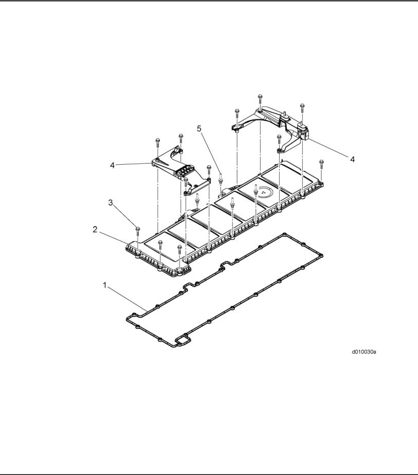
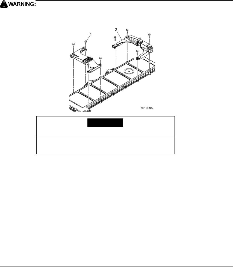
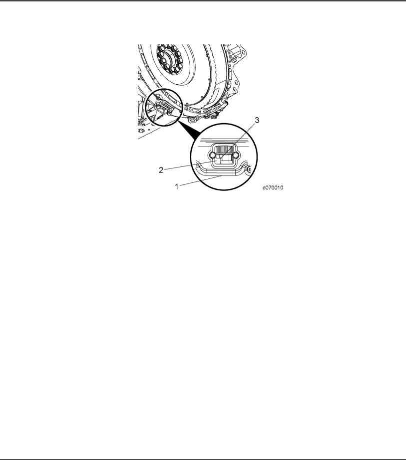
1.1DESCRIPTION AND OPERATION OF ROCKER COVER AND RELATED PARTS
The rocker cover (2) is made of an aluminum or plastic material and uses an elastomer seal (1) which completely encloses the valve operating mechanism including the overhead camshafts, brake assemblies and the injector harness.
1. |
Gasket |
4. |
Air Cleaner Bracket |
2. |
Rocker Cover |
5. |
Stud (Bolt) |
3. |
Bolt |
|
|
Figure 1-1 |
Rocker Cover |
|
|
All information subject to change without notice. |
1-3 |
DDC-SVC-MAN-0081 2010 Copyright © 2010 DETROIT DIESEL CORPORATION |
1.2REMOVAL OF THE ROCKER COVER
1.2REMOVAL OF THE ROCKER COVER
Remove as follows:
1.Steam clean the engine.
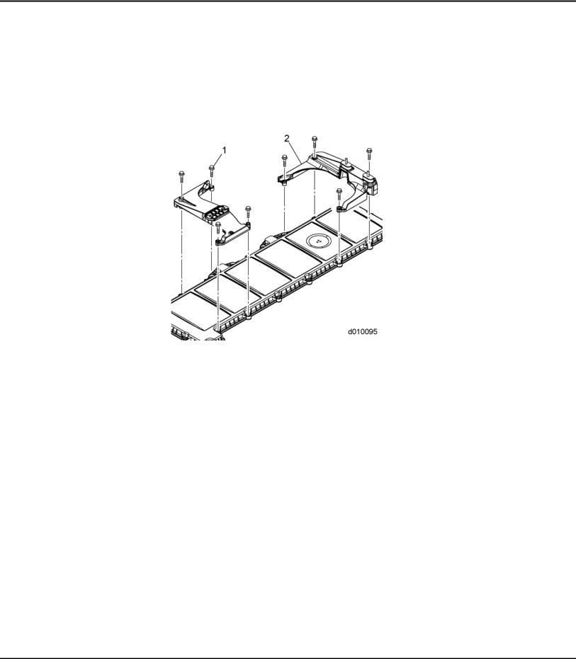
2.Remove bolts (1) or nuts (if equipped) from the two air filter housing brackets (2) and remove housings from the rocker cover.
1-4 |
All information subject to change without notice. |
DDC-SVC-MAN-0081 2010 Copyright © 2010 DETROIT DIESEL CORPORATION |
EPA07/10 DD PLATFORM WORKSHOP MANUAL - ENGINE
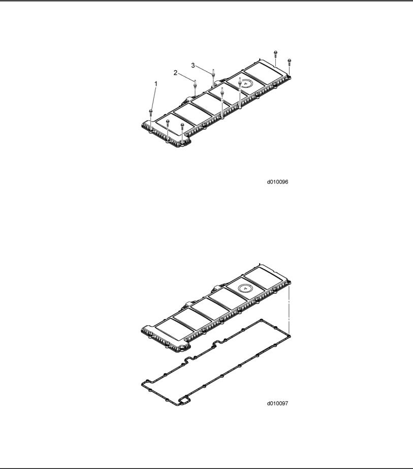
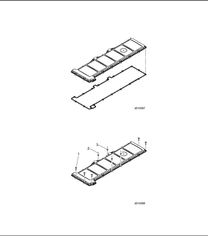
3. Loosen the bolts (1) or stud bolts (2) (if equipped) and isolators (3); remove rocker cover.
NOTE:
Mark the location of the stud bolts. The stud bolts must be replaced in their original location during installation.
4. Remove rocker cover gasket from the rocker cover.
All information subject to change without notice. |
1-5 |
DDC-SVC-MAN-0081 2010 Copyright © 2010 DETROIT DIESEL CORPORATION |

1.3CLEANING AND INSPECTION OF THE ROCKER COVER
1.3CLEANING AND INSPECTION OF THE ROCKER COVER
Clean as follows:
1. Clean cover in clean solvent or fuel.
EYE INJURY
To avoid injury from flying debris when using compressed air, wear adequate eye protection (face shield or safety goggles) and do not exceed 276 kPa (40 psi) air pressure.
2.Blow dry with compressed air.
3.Check the rocker cover, breather passage and seal for damage. Replace as necessary.
4.Inspect the bolts. Replace if damaged.
1-6 |
All information subject to change without notice. |
DDC-SVC-MAN-0081 2010 Copyright © 2010 DETROIT DIESEL CORPORATION |
EPA07/10 DD PLATFORM WORKSHOP MANUAL - ENGINE
1.4INSTALLATION OF THE ROCKER COVER
Install as follows:
1. Install rocker cover gasket into groove in rocker cover.
2. Install bolts (1) or stud bolts (2) (if removed) and isolators (3) into rocker cover.
3.Install rocker cover onto camshaft housing.
4.Finger tighten all bolts (1) and stud bolts; then torque to 20 N·m (14 lb·ft).
All information subject to change without notice. |
1-7 |
DDC-SVC-MAN-0081 2010 Copyright © 2010 DETROIT DIESEL CORPORATION |
1.4INSTALLATION OF THE ROCKER COVER
5.Install the two air filter brackets (2) (if equipped), onto the rocker cover and torque the eight nuts to 20 N·m (14 lb·ft).
ENGINE EXHAUST
To avoid injury from inhaling engine exhaust, always operate the engine in a well-ventilated area. Engine exhaust is toxic.
6. Start the engine and check for leaks.
1-8 |
All information subject to change without notice. |
DDC-SVC-MAN-0081 2010 Copyright © 2010 DETROIT DIESEL CORPORATION |

2CAMSHAFT AND ROCKER SHAFT/ENGINE BRAKE ASSEMBLY
Section |
Page |
2.1DESCRIPTION AND OPERATION OF CAMSHAFT AND ROCKER
SHAFT/ENGINE BRAKE ASSEMBLY AND RELATED PARTS ............... |
2-3 |
2.2REMOVAL OF CAMSHAFT AND ROCKER SHAFT/ENGINE BRAKE
ASSEMBLY .............................................................................................. |
2-7 |
2.3INSPECTION OF THE CAMSHAFT AND ROCKER SHAFT/ENGINE
BRAKE ASSEMBLY ................................................................................. |
2-15 |
2.4INSTALLATION OF THE CAMSHAFT AND ROCKER SHAFT/ENGINE
BRAKE ASSEMBLY ................................................................................. |
2-16 |
2.5DD13 EGR COOLER CLEANING PROCEDURE TO REMOVE EXCESS
FUEL FROM COOLER AFTER ENGINE BRAKE SOLENOID FAILURE 2-26
2.6DD15 EGR COOLER CLEANING PROCEDURE TO REMOVE EXCESS
FUEL FROM COOLER AFTER ENGINE BRAKE SOLENOID FAILURE 2-31

2-2 |
All information subject to change without notice. |
DDC-SVC-MAN-0081 2010 Copyright © 2010 DETROIT DIESEL CORPORATION |
EPA07/10 DD PLATFORM WORKSHOP MANUAL - ENGINE
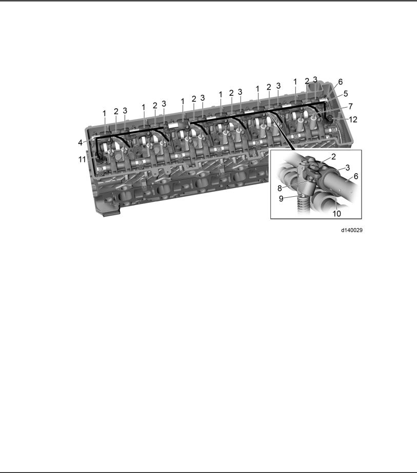
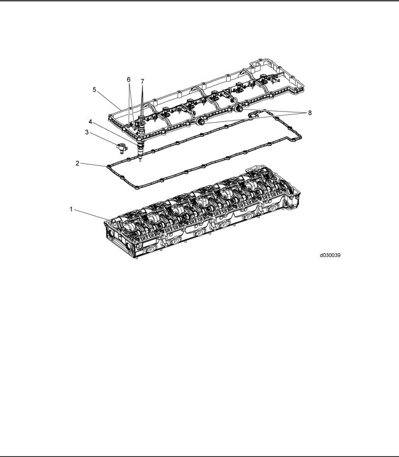
2.1DESCRIPTION AND OPERATION OF CAMSHAFT AND ROCKER SHAFT/ENGINE BRAKE ASSEMBLY AND RELATED PARTS
The engine uses a dual overhead camshaft and rocker shaft design. The intake and exhaust camshafts are timed to each other, through a geartrain, to the crankshaft. The camshaft housing houses the camshafts and valve train. It has internal oil passages to supply oil from the block to the camshaft and rocker bearings along with pressurized oil to the engine brake rockers via the engine brake solenoids through the exhaust shaft. The camshaft housing is made of aluminium material.
1. |
Camshaft Bearing Cap |
6. |
Intake Rocker Arm |
11. Gasket |
||
2. |
Bolt 120 mm |
|
7. |
Exhaust Rocker Arm |
12. |
Exhaust Camshaft Lobes |
3. |
Bolt 108 mm |
|
8. Exhaust Camshaft and Gear |
13. |
Exhaust Camshaft Brake Cam |
|
|
|
|
|
|
Lobe |
|
4. |
Bolt 63 mm |
|
9. |
Intake Camshaft and Gear |
14. |
Intake Camshaft Lobes |
5. |
Engine Brake Solenoid |
10. Camshaft Housing |
15. |
Intake Camshaft Tone Wheel |
||
Figure 2-1 |
Camshaft Housing and Related Parts |
|
|
|||
|
|
|
|
|
||
All information subject to change without notice. |
|
|
|
2-3 |
||
DDC-SVC-MAN-0081 2010 Copyright © 2010 DETROIT DIESEL CORPORATION |
|
|||||

2.1 DESCRIPTION AND OPERATION OF CAMSHAFT AND ROCKER SHAFT/ENGINE BRAKE ASSEMBLY AND RELATED PARTS
2.1.1Engine Braking
The engine uses an integral engine brake. Engine braking is controlled electronically by the engine control system with an electric solenoid. When activated, the solenoid allows oil pressure to activate a piston on the exhaust rocker arm. Engine braking is accomplished with a single exhaust valve in each cylinder. The exhaust camshaft uses a separate engine brake-only lobe that allows for double valve activation for high efficiency braking. The exhaust valve is first operated toward the completion of the intake stroke, closed during the compression stroke and opened a second time when the compression stroke is completed. The engine brake system is enabled using the following components:
For EPA07 engines:
□Engine brake solenoid valve in front of engine applies low engine braking.
□Engine brake solenoid valve in rear of engine applies medium engine braking.
□For high, both front and rear solenoids are activated.
□Six exhaust rocker arms with actuator pistons.
□Six brake rocker arms which are actuated by the brake cam lobes.
□Exhaust camshaft has one brake cam lobe per cylinder.
2-4 |
All information subject to change without notice. |
DDC-SVC-MAN-0081 2010 Copyright © 2010 DETROIT DIESEL CORPORATION |
EPA07/10 DD PLATFORM WORKSHOP MANUAL - ENGINE
For EPA07 engines, the exhaust rocker arm shaft lubricating oil passages direct pressurized oil to the rocker arms. The exhaust rocker arm has two additional oil passages to operate the engine brakes. Oil for cylinders 1 and 2 is supplied by the Front Engine Brake Solenoid Valve. Oil for cylinders 3 to 6 are supplied by the Rear Engine Brake Solenoid Valve.
1. |
Exhaust Rocker Arm |
7. |
Exhaust Camshaft |
2. |
Exhaust Rocker Arm with Actuator Piston |
8. |
Actuator Piston |
3. |
Brake Rocker Arm |
9. |
Exhaust Valve |
4. |
Oil Passage for Cylinders 1 and 2 |
10. |
Brake Cam Lobe |
5. |
Oil Passage for Cylinders 3, 4, 5 and 6 |
11. Engine Brake Solenoid Valve, Front |
|
6. |
Exhaust Rocker Arm Shaft |
12. |
Engine Brake Solenoid Valve, Rear |
Figure 2-2 EPA07 Engine Brake
For EPA10 engines:
□Engine brake solenoid valve in front of engine applies low engine braking.
□For medium engine braking, both front and rear solenoids are activated.
□For high, both front and rear solenoids are activated, along with EGR.
□Six exhaust rocker arms with actuator pistons.
□Six brake rocker arms which are actuated by the brake cam lobes.
□Exhaust camshaft has one brake cam lobe per cylinder.
All information subject to change without notice. |
2-5 |
DDC-SVC-MAN-0081 2010 Copyright © 2010 DETROIT DIESEL CORPORATION |

2.1 DESCRIPTION AND OPERATION OF CAMSHAFT AND ROCKER SHAFT/ENGINE BRAKE ASSEMBLY AND RELATED PARTS
For EPA10 engines, the exhaust rocker arm shaft lubricating oil passages direct pressurized oil to the rocker arms. The exhaust rocker arm has two additional oil passages to operate the engine brakes. Oil for cylinders 1 through 3 is supplied by the Front Engine Brake Solenoid Valve. Oil for cylinders 4 through 6 are supplied by the Rear Engine Brake Solenoid Valve.
1. |
Exhaust Rocker Arm |
7. |
Exhaust Camshaft |
2. |
Exhaust Rocker Arm with Actuator Piston |
8. |
Actuator Piston |
3. |
Brake Rocker Arm |
9. |
Exhaust Valve |
4. |
Oil Passage for Cylinders 1, 2 and 3 |
10. |
Brake Cam Lobe |
5. |
Oil Passage for Cylinders 4, 5 and 6 |
11. Engine Brake Solenoid Valve, Front |
|
6. |
Exhaust Rocker Arm Shaft |
12. |
Engine Brake Solenoid Valve, Rear |
Figure 2-3 EPA10 Engine Brake
2-6 |
All information subject to change without notice. |
DDC-SVC-MAN-0081 2010 Copyright © 2010 DETROIT DIESEL CORPORATION |
EPA07/10 DD PLATFORM WORKSHOP MANUAL - ENGINE
2.2REMOVAL OF CAMSHAFT AND ROCKER SHAFT/ENGINE BRAKE ASSEMBLY
Remove as follows:
1.Turn engine OFF, (key OFF, engine OFF).
2.Steam clean the engine.
3.Disconnect the battery power to the engine. Refer to OEM procedures.
4.Remove the air cleaner and the turbocharger inlet pipe and hose. Refer to OEM procedures.
5.Remove air cleaner housing. Refer to OEM procedures.
6.Remove the rocker cover. Refer to section 1.2.
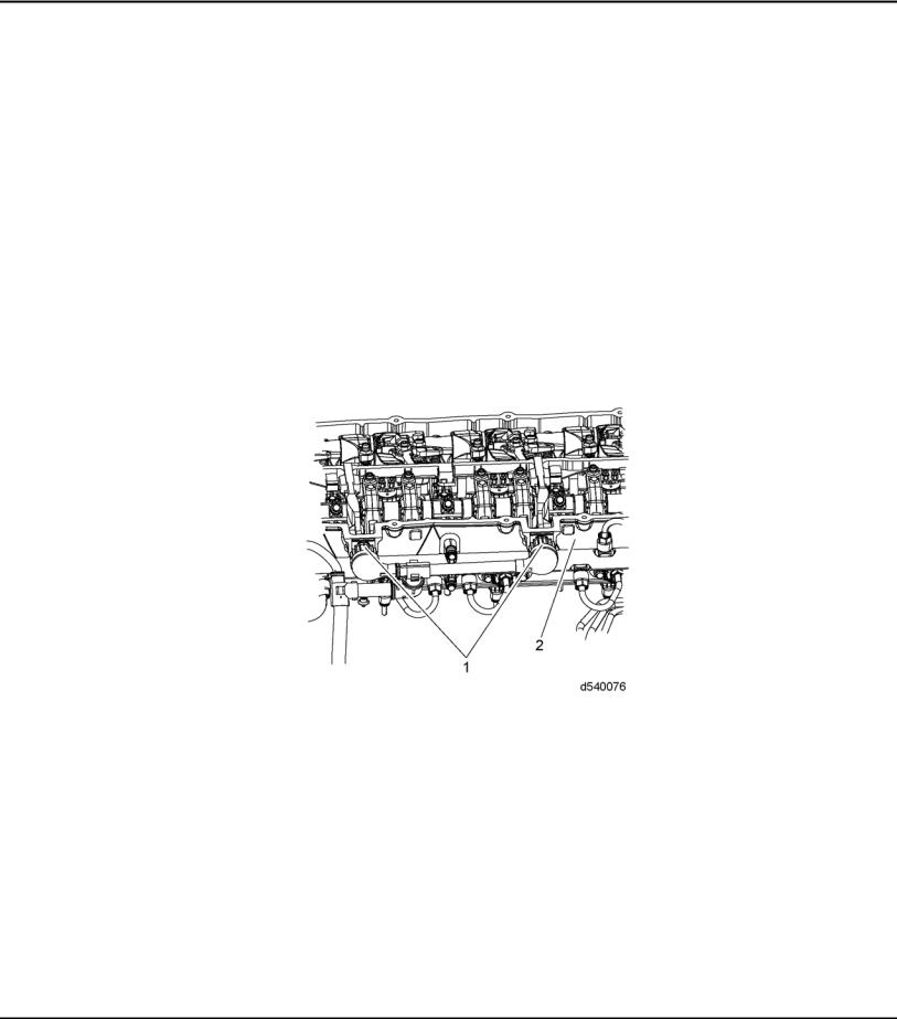
7.Remove the two 14-pin fuel injector harness connectors (1) from the camshaft housing housing (2).
NOTE:
Top Dead Center (TDC) can be confirmed by installing camshaft timing tool. For the DD13 use Camshaft Timing Tool (W470589034000). For the EPA07 DD15 use
Camshaft Timing Tool (W470589054000). For the EPA10 DD15 use Camshaft Timing Tool (W470589104000).
8. Using Engine Barring tool (J-46392), rotate the crankshaft to TDC on cylinder No. 1.
All information subject to change without notice. |
2-7 |
DDC-SVC-MAN-0081 2010 Copyright © 2010 DETROIT DIESEL CORPORATION |
2.2REMOVAL OF CAMSHAFT AND ROCKER SHAFT/ENGINE BRAKE ASSEMBLY
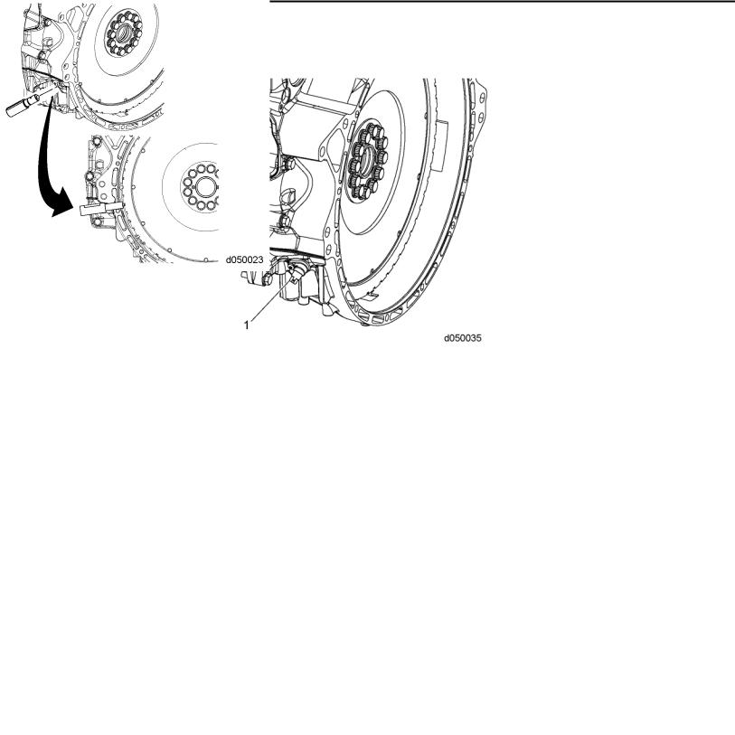
9.Remove the Crankshaft Position Sensor (CKP) (1) from the rear of the flywheel housing. Refer to section .
10.To accurately locate TDC, install the flywheel housing crankshaft TDC Locating Pin (W470589001500) into the CKP sensor hole located in the rear of the flywheel housing. The plastic tip will protrude into the cutout in the tone wheel. TDC can be verified by the proper installation of the camshaft timing tool.
|
|
|
|
|
|
2-8 |
All information subject to change without notice. |
|
DDC-SVC-MAN-0081 2010 Copyright © 2010 DETROIT DIESEL CORPORATION |
||
EPA07/10 DD PLATFORM WORKSHOP MANUAL - ENGINE
11.When the TDC dot (3) between two teeth on the flywheel aligns with the edge of pointer (2), the engine is at TDC firing stroke.
12.For EPA07 DD13:
[a]Disconnect both 14-pin injector harness connectors (8).
[b]Disconnect the 24 electrical terminals at the fuel injectors (7).
[c]Disconnect two wiring terminals at each engine brake solenoid (6).
All information subject to change without notice. |
2-9 |
DDC-SVC-MAN-0081 2010 Copyright © 2010 DETROIT DIESEL CORPORATION |
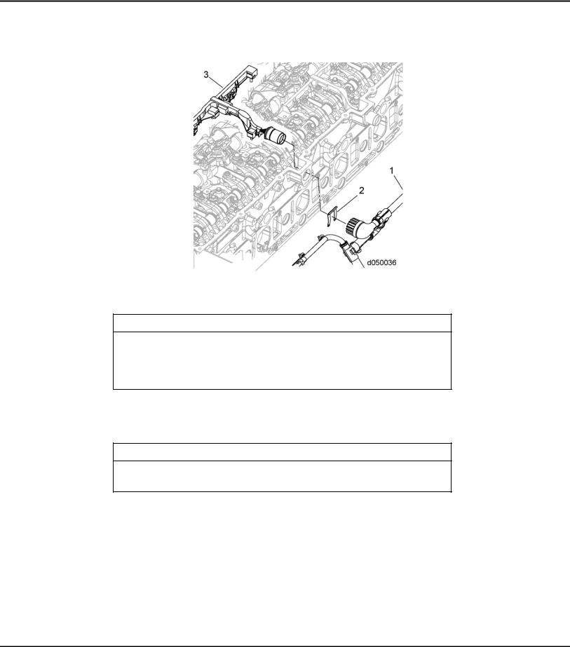
2.2REMOVAL OF CAMSHAFT AND ROCKER SHAFT/ENGINE BRAKE ASSEMBLY
[d]Loosen the Allen screws holding the intermediate frame (5) to the camshaft housing
(1). Remove the intermediate frame .
13.For EPA10 engines:
[a]Remove the fuel injector electrical harness clips (2) from the 14-pin electrical connectors.
2-10 |
All information subject to change without notice. |
DDC-SVC-MAN-0081 2010 Copyright © 2010 DETROIT DIESEL CORPORATION |
EPA07/10 DD PLATFORM WORKSHOP MANUAL - ENGINE
[b]Remove the bolts securing the two-piece fuel injector electrical harness (1 and 3) and remove the harness from the camshaft housing housing.
14. Remove the engine brake solenoids from the camshaft housing.
NOTICE:
Ensure when loosening the rocker shaft bolts that the bolts are loosened from the inside bolts outward in 1/2 turn increments. The increment procedure needs to be followed to prevent the rocker shaft from breaking.
15.Completely loosen all of the adjusting screws on all of the rocker arms.
16.Loosen the seven bolts securing the intake rocker shaft to the camshaft bearing caps.
NOTICE:
Make sure that the camshaft housing housing is not damaged during removal of the intake/exhaust rocker shaft assemblies.
All information subject to change without notice. |
2-11 |
DDC-SVC-MAN-0081 2010 Copyright © 2010 DETROIT DIESEL CORPORATION |
2.2REMOVAL OF CAMSHAFT AND ROCKER SHAFT/ENGINE BRAKE ASSEMBLY
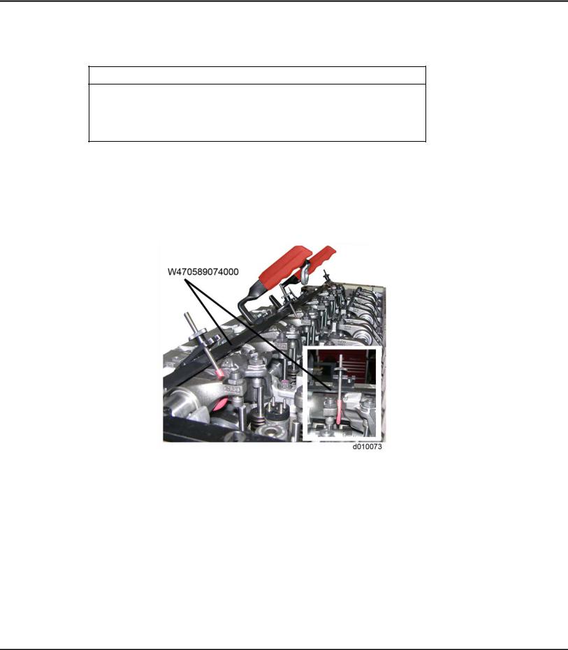
17.Using Rocker Arm Lifter / Spacer tool (W470589044000) for the DD13, or Rocker Arm Lifter / Spacer Intake tool (W470589004000) for the DD15, remove the intake rocker shaft assembly.
NOTICE:
Ensure when loosening the rocker shaft bolts that the bolts are loosened from the inside bolts outward in 1/2 turn increments. The increment procedure needs to be followed to prevent the rocker shaft from breaking.
18.Loosen the seven bolts securing the exhaust rocker shaft to the camshaft caps.
19.Using Rocker Arm Lifter / Spacer Exhaust (W470589074000) for the DD13 or Rocker Arm Lifter / Spacer Exhaust (W470589004000) for the DD15, remove the exhaust rocker shaft assembly. When removing the EPA10 exhaust rocker shaft, ensure the rockers are in the up position.
NOTE:
The engine brake solenoids do not have to be removed unless damaged.
NOTE:
Mark cap position for proper reassembly.
2-12 |
All information subject to change without notice. |
DDC-SVC-MAN-0081 2010 Copyright © 2010 DETROIT DIESEL CORPORATION |
 Loading...