


SERIES 60 SERVICE MANUAL
ABSTRACT
This manual provides instruction for servicing on-highway applications of the Detroit Diesel Series 60 Diesel and Natural Gas-Fueled Engines.
Specifically a basic overview of each major component and system along with recommendations for removal, cleaning, inspection, criteria for replacement, repair and installation and mechanical troubleshooting are contained in this manual.
DDEC III/IV troubleshooting concerns are contained in the DDEC III/IV Single ECM Troubleshooting Guide, 6SE497.
DDEC V troubleshooting concerns are contained in the DDEC V Troubleshooting Guide, 6SE570.
All information subject to change without notice. (Rev. 2005) |
i |
6SE483 0507 Copyright © 2005 DETROIT DIESEL CORPORATION |

SERIES 60 SERVICE MANUAL
ENGINE EXHAUST
Consider the following before servicing engines:
PERSONAL INJURY
Diesel engine exhaust and some of its constituents are known to the State of California to cause cancer, birth defects, and other reproductive harm.
□Always start and operate an engine in a well ventilated area.
□If operating an engine in an enclosed area, vent the exhaust to the outside.
□Do not modify or tamper with the exhaust system or emission control system.
ii |
(Rev. 2005) All information subject to change without notice. |
6SE483 0507 Copyright © 2005 DETROIT DIESEL CORPORATION |

SERIES 60 SERVICE MANUAL
REVISION NOTIFICATION
Modifications to this manual are announced in the form of Service Information Bulletins. The bulletins include attachment pages and are posted on the World Wide Web (www.detroitdiesel.com/svc/sibindex.htm).
Revisions to this manual will be sent marked with a revision bar (see Example 2). Sections containing revisions will have a third line in the page footer (compare Examples 1 and 2).
All information subject to change without notice. (Rev. 2005) |
iii |
6SE483 0507 Copyright © 2005 DETROIT DIESEL CORPORATION |

SERIES 60 SERVICE MANUAL
iv |
(Rev. 2005) All information subject to change without notice. |
6SE483 0507 Copyright © 2005 DETROIT DIESEL CORPORATION |

SERIES 60 SERVICE MANUAL
TABLE OF CONTENTS
|
GENERAL INFORMATION ...................................................................... |
1 |
|
SCOPE AND USE OF THIS MANUAL .................................................... |
3 |
|
CLEARANCE OF NEW PARTS AND WEAR LIMITS .............................. |
3 |
|
THE FOUR CYCLE PRINCIPLE FOR DIESEL ENGINES ...................... |
4 |
|
FOUR CYCLE PRINCIPLE FOR NATURAL GAS ENGINES .................. |
6 |
|
GENERAL DESCRIPTION ...................................................................... |
8 |
|
GENERAL SPECIFICATIONS ................................................................. |
14 |
|
GENERAL SPECIFICATIONS FOR THE SERIES 60G ENGINE ............ |
15 |
|
ENGINE MODEL, SERIAL NUMBER AND OPTION LABEL ................... |
16 |
|
ENGINE MODEL, SERIAL NUMBER AND OPTION LABEL (SERIES |
|
|
60G ENGINE) .......................................................................................... |
19 |
|
REPLACING AND REPAIRING ............................................................... |
20 |
|
DISASSEMBLY ........................................................................................ |
20 |
|
CLEANING ............................................................................................... |
21 |
|
SAFETY PRECAUTIONS ....................................................................... |
27 |
|
FLUOROELASTOMER (VITON) CAUTION ............................................. |
40 |
|
ENGINE VIEWS ....................................................................................... |
41 |
|
ENGLISH TO METRIC CONVERSION .................................................... |
46 |
|
DECIMAL AND METRIC EQUIVALENTS ................................................ |
47 |
|
SPECIFICATIONS ................................................................................... |
48 |
1 |
ENGINE |
|
1.1 |
CYLINDER BLOCK AND CYLINDER LINER .......................................... |
1-3 |
1.2 |
CYLINDER HEAD .................................................................................... |
1-30 |
1.3 |
VALVE AND INJECTOR OPERATING MECHANISM .............................. |
1-60 |
1.4 |
VALVES, SPRINGS, GUIDES, INSERTS, SEALS AND ROTATORS ...... |
1-79 |
1.5 |
ENGINE LIFTER BRACKETS .................................................................. |
1-106 |
1.6 |
ROCKER COVER .................................................................................... |
1-111 |
1.7 |
CRANKSHAFT ........................................................................................ |
1-129 |
1.8 |
CRANKSHAFT OIL SEALS ..................................................................... |
1-150 |
1.9 |
CRANKSHAFT MAIN BEARINGS ........................................................... |
1-164 |
1.10 |
GEAR CASE COVER PRE-EXHAUST GAS RECIRCULATION (EGR) .. |
1-175 |
1.11GEAR CASE COVER EXHAUST GAS RECIRCULATION (EGR)
|
MODEL .................................................................................................... |
1-190 |
1.12 |
GEAR CASE PRE-EXHAUST GAS RECIRCULATION (EGR) ................ |
1-210 |
1.13 |
GEAR CASE EXHAUST GAS RECIRCULATION (EGR) MODEL ........... |
1-231 |
1.14 |
CRANKSHAFT VIBRATION DAMPER .................................................... |
1-242 |
1.15 |
CRANKSHAFT PULLEY .......................................................................... |
1-252 |
1.16 |
FLYWHEEL ............................................................................................. |
1-266 |
1.17 |
RING GEAR ............................................................................................. |
1-275 |
1.18 |
FLYWHEEL HOUSING ............................................................................ |
1-277 |
1.19 |
PISTON AND PISTON RING ................................................................... |
1-285 |
All information subject to change without notice. (Rev. 2005) |
v |
6SE483 0507 Copyright © 2005 DETROIT DIESEL CORPORATION |

SERIES 60 SERVICE MANUAL
1.20 |
ONE-PIECE PISTON ASSEMBLY AND PISTON RING .......................... |
1-306 |
1.21 |
PISTON AND CONNECTING ROD ASSEMBLY ..................................... |
1-318 |
1.22 |
CONNECTING ROD ................................................................................ |
1-345 |
1.23 |
CYLINDER LINER ................................................................................... |
1-360 |
1.24 |
GEAR TRAIN AND ENGINE TIMING ...................................................... |
1-373 |
1.25 |
COMPACT GEAR TRAIN AND ENGINE TIMING ................................... |
1-399 |
1.26CAMSHAFT GEAR ASSEMBLY SERIES 60 EXHAUST GAS
|
RECIRCULATION (EGR) MODEL ........................................................... |
1-418 |
1.27 |
THRUST PLATE PERIMETER SEAL ...................................................... |
1-445 |
1.28 |
CAMSHAFT AND CAMSHAFT BEARING ............................................... |
1-458 |
1.29 |
CAMSHAFT DRIVE GEAR ...................................................................... |
1-490 |
1.30 |
ADJUSTABLE IDLER GEAR ASSEMBLY ............................................... |
1-503 |
1.31 |
ADJUSTABLE IDLER GEAR COMPACT GEAR TRAIN .......................... |
1-512 |
1.32BULL GEAR AND CAMSHAFT IDLER GEAR FOR THE COMPACT
|
GEAR TRAIN ........................................................................................... |
1-518 |
1.33 |
BULL GEAR AND CAMSHAFT IDLER GEAR ASSEMBLY ..................... |
1-525 |
1.34 |
CRANKSHAFT TIMING GEAR AND TIMING WHEEL ............................ |
1-538 |
1.35 |
ACCESSORY DRIVE ............................................................................... |
1-557 |
1.36 |
JAKE BRAKE ........................................................................................... |
1-585 |
1.A |
ADDITIONAL INFORMATION .................................................................. |
1-639 |
2 |
FUEL SYSTEM |
|
2.1 |
DIESEL FUEL SYSTEM OVERVIEW ...................................................... |
2-5 |
2.2 |
VEHICLE SAFETY FOR THE NATURAL GAS ENGINE ......................... |
2-7 |
2.3 |
N2 ELECTRONIC UNIT INJECTOR ....................................................... |
2-11 |
2.4 |
N2 FUEL INJECTOR TUBE AND O-RING .............................................. |
2-28 |
2.5 |
N3 ELECTRONIC UNIT INJECTOR ....................................................... |
2-42 |
2.6 |
N3 FUEL INJECTOR TUBE .................................................................... |
2-55 |
2.7 |
FUEL PUMP WITH SEPARATE DRIVE SHAFT AND HUB ..................... |
2-58 |
2.8 |
FUEL PUMP WITH ONE-PIECE DRIVE SHAFT AND HUB ASSEMBLY |
2-79 |
2.9 |
FUEL PUMP DRIVE ................................................................................. |
2-99 |
2.10 |
DIESEL FUEL FILTERS (SPIN-ON) ........................................................ |
2-104 |
2.11 |
FUEL PRO 380/380E FUEL FILTER SYSTEM ........................................ |
2-112 |
2.12 |
FUEL FILTER TYPE FOR THE SERIES 60G ENGINE ........................... |
2-118 |
2.13 |
ASSEMBLY FUEL FILTER AND WATER SEPARATOR .......................... |
2-126 |
2.14 |
ELECTRONIC ENGINE CONTROL ......................................................... |
2-133 |
2.15 |
DDEC V ELECTRONIC CONTROL UNIT ............................................... |
2-135 |
2.16 |
DDEC III/IV ELECTRONIC CONTROL MODULE ................................... |
2-141 |
2.17 |
DDEC II ELECTRONIC CONTROL MODULE ......................................... |
2-149 |
2.18 |
DDEC I ..................................................................................................... |
2-159 |
2.19 |
PROGRAMMABLE READ-ONLY MEMORY (PROM) DDEC I ............... |
2-165 |
2.20 |
ELECTRONIC DISTRIBUTOR UNIT DDEC I ......................................... |
2-169 |
2.21 |
ELECTRONIC FOOT PEDAL ASSEMBLY ............................................. |
2-172 |
2.22 |
TURBO SPEED SENSOR (TSS) ............................................................. |
2-173 |
2.23 |
TURBO BOOST PRESSURE SENSOR .................................................. |
2-177 |
2.24 |
AIR INTAKE PRESSURE SENSOR ......................................................... |
2-179 |
2.25 |
OIL PRESSURE SENSOR ..................................................................... |
2-181 |
vi |
(Rev. 2005) All information subject to change without notice. |
6SE483 0507 Copyright © 2005 DETROIT DIESEL CORPORATION |

|
|
SERIES 60 SERVICE MANUAL |
|
|
|
2.26 |
OIL TEMPERATURE SENSOR |
.............................................................. 2-183 |
2.27 |
AIR TEMPERATURE SENSOR ............................................................... |
2-185 |
2.28AIR TEMPERATURE SENSOR FOR HIGH PRESSURE FUEL
SYSTEM .................................................................................................. |
2-188 |
2.29 COOLANT TEMPERATURE SENSOR .................................................... |
2-190 |
2.30SYNCHRONOUS REFERENCE SENSOR GEAR CASE MOUNTED .... 2-192
2.31SYNCHRONOUS REFERENCE SENSOR \ CAMSHAFT POSITION
|
SENSOR CAMSHAFT GEAR COVER MOUNTED ................................. |
2-194 |
2.32 |
TIMING REFERENCE SENSOR ............................................................ |
2-197 |
2.33 |
COOLANT LEVEL SENSOR .................................................................. |
2-199 |
2.34 |
FUEL PRESSURE SENSOR .................................................................. |
2-203 |
2.35 |
FUEL TEMPERATURE SENSOR ........................................................... |
2-205 |
2.36 |
EXHAUST GAS OXYGEN SENSOR FOR SERIES 60G ENGINES ....... |
2-208 |
2.37EXHAUST TEMPERATURE SENSOR FOR THE SERIES 60G
ENGINES ................................................................................................. |
2-211 |
2.38KNOCK SENSOR AND SIGNAL NOISE ENHANCEMENT FILTER
MODULE .................................................................................................. |
2-212 |
2.39BAROMETRIC PRESSURE SENSOR FOR THE SERIES 60G ENGINE
WITH HIGH PRESSURE FUEL SYSTEM .............................................. |
2-215 |
2.40OVERVIEW OF HIGH PRESSURE FUEL SYSTEM FOR SERIES 60G
ENGINES ................................................................................................. |
2-217 |
2.41FUEL PRESSURE GAGES FOR THE SERIES 60G ENGINE WITH A
HIGH PRESSURE FUEL SYSTEM ......................................................... |
2-223 |
2.42VENTING AND LEAK CHECKING PROCEDURES FOR A NATURAL
GAS ENGINE (HIGH PRESSURE SYSTEM) ......................................... |
2-225 |
2.43HIGH PRESSURE FUEL REGULATOR FOR THE SERIES 60G
ENGINE ................................................................................................... |
2-229 |
2.44PULSE WIDTH MODULATED STEPPER MOTOR VALVE (PSV) FOR
SERIES 60G AUTOMOTIVE ENGINES .................................................. |
2-231 |
2.45FUEL MIXER FOR THE SERIES 60G HIGH PRESSURE FUEL SYSTEM
.................................................................................................................. 2-234
2.46FUEL SHUTOFF VALVE FOR SERIES 60G ENGINE WITH HIGH
PRESSURE FUEL SYSTEM ................................................................... |
2-237 |
2.47IMPCO LOW PRESSURE FUEL REGULATOR FOR THE SERIES 60G
ENGINE HIGH PRESSURE FUEL SYSTEM .......................................... |
2-239 |
2.48OVERVIEW OF THE LOW PRESSURE NATURAL GAS FUEL
SYSTEM .................................................................................................. |
2-243 |
2.49LOW PRESSURE FUEL REGULATOR FOR THE SERIES 60G
ENGINE ................................................................................................... |
2-248 |
2.50 FUEL MIXER FOR THE SERIES 60G LOW PRESSURE SYSTEM ....... |
2-252 |
2.51VENTING AND LEAK CHECKING PROCEDURES FOR NATURAL GAS
|
ENGINE (LOW PRESSURE SYSTEM) .................................................. |
2-255 |
2.A |
ADDITIONAL INFORMATION .................................................................. |
2-257 |
3 |
LUBRICATION SYSTEM |
|
3.1 |
OVERVIEW OF LUBRICATING SYSTEM ............................................... |
3-3 |
3.2 |
OIL PUMP ................................................................................................ |
3-8 |
All information subject to change without notice. (Rev. 2005) |
vii |
6SE483 0507 Copyright © 2005 DETROIT DIESEL CORPORATION |

SERIES 60 SERVICE MANUAL
3.3 |
OIL PRESSURE REGULATOR VALVE ................................................... |
3-21 |
3.4 |
OIL PRESSURE RELIEF VALVE ............................................................. |
3-28 |
3.5 |
OIL FILTER .............................................................................................. |
3-34 |
3.6 |
OIL FILTER ADAPTOR ............................................................................ |
3-36 |
3.7 |
THERMATIC OIL CONTROL VALVE ....................................................... |
3-41 |
3.8 |
OIL COOLER (1991 AND LATER ENGINES) .......................................... |
3-49 |
3.9 |
OIL COOLER (PRE-1991 ENGINES) ...................................................... |
3-59 |
3.10 |
OIL LEVEL DIPSTICK ASSEMBLY ......................................................... |
3-69 |
3.11 |
OIL PAN ................................................................................................... |
3-74 |
3.12 |
VENTILATING SYSTEM .......................................................................... |
3-82 |
3.A |
ADDITIONAL INFORMATION .................................................................. |
3-91 |
4 |
COOLING SYSTEM |
|
4.1 |
COOLING SYSTEM OVERVIEW ............................................................. |
4-3 |
4.2 |
WATER PUMP (GEAR-CASE MOUNTED - 1991 AND LATER) (GCM) .. |
4-7 |
4.3 |
WATER PUMP (FRONT MOUNTED) (FM) .............................................. |
4-33 |
4.4 |
THERMOSTAT ........................................................................................ |
4-58 |
4.5 |
COOLANT PRESSURE CONTROL CAP ................................................ |
4-69 |
4.6 |
ENGINE COOLING FAN .......................................................................... |
4-72 |
4.7 |
COOLANT FILTER AND CONDITIONER ................................................ |
4-82 |
4.8 |
RADIATOR ............................................................................................... |
4-84 |
4.A |
ADDITIONAL INFORMATION .................................................................. |
4-85 |
5 |
FUEL, LUBRICATING OIL, AND COOLANT |
|
5.1 |
FUEL ........................................................................................................ |
5-3 |
5.2 |
LUBRICATING OIL (DIESEL) .................................................................. |
5-10 |
5.3 |
LUBRICATING OIL FOR THE SERIES 60G ENGINE ............................. |
5-15 |
5.4 |
COOLANT ................................................................................................ |
5-17 |
6 |
AIR INTAKE SYSTEM |
|
6.1 |
AIR INTAKE SYSTEM OVERVIEW ......................................................... |
6-3 |
6.2 |
AIR CLEANER ......................................................................................... |
6-7 |
6.3 |
INTAKE MANIFOLD ................................................................................. |
6-9 |
6.4CLOSED CRANKCASE BREATHER FOR SERIES 60G AUTOMOTIVE
ENGINES ................................................................................................. |
6-18 |
6.5 TURBOCHARGER (DIESEL) .................................................................. |
6-20 |
6.6TURBOCHARGER SERIES 60 NATURAL GAS (AUTOMOTIVE)
|
ENGINE ................................................................................................... |
6-43 |
6.7 |
RECIRCULATION VALVE FOR SERIES 60G AUTOMOTIVE ENGINE .. |
6-61 |
6.8 |
CHARGE AIR COOLER ........................................................................... |
6-63 |
6.9 |
THROTTLE ACTUATOR FOR THE SERIES 60G ENGINE .................... |
6-72 |
6.10 |
AIR DRYER .............................................................................................. |
6-76 |
6.A |
ADDITIONAL INFORMATION .................................................................. |
6-77 |
7 |
EXHAUST SYSTEM |
|
7.1 |
OVERVIEW OF EXHAUST MANIFOLD COMPONENTS ........................ |
7-3 |
7.2 |
THREE-PIECE EXHAUST MANIFOLD WITH FEY RINGS ..................... |
7-7 |
7.3 |
THREE-PIECE EXHAUST MANIFOLD WITHOUT FEY RINGS ............. |
7-16 |
7.4 |
THREE-PIECE EXHAUST MANIFOLD WITH HEAT SHIELD ................. |
7-23 |
viii |
(Rev. 2005) All information subject to change without notice. |
6SE483 0507 Copyright © 2005 DETROIT DIESEL CORPORATION |
|
SERIES 60 SERVICE MANUAL |
|
|
|
|
8 |
EXHAUST GAS RECIRULATION (EGR) COMPONENTS |
|
8.1 |
TUBE AND SHELL BOLTED FLANGE EGR COOLER ........................... |
8-3 |
8.2 |
HYDRAULIC EGR VALVE ........................................................................ |
8-19 |
8.3 |
DELIVERY PIPE ...................................................................................... |
8-28 |
8.4 |
EGR RATE MEASUREMENT SYSTEM .................................................. |
8-40 |
8.5 |
DDEC V VARIBLE PRESSURE OUTPUT DEVICE ................................. |
8-44 |
8.6 |
DDEC IV VARIBLE PRESSURE OUTPUT DEVICES ............................. |
8-48 |
9 |
ELECTRICAL EQUIPMENT |
|
9.1 |
OVERVIEW OF ELECTRICAL SYSTEM ................................................. |
9-3 |
9.2 |
BATTERY CHARGING ALTERNATOR .................................................... |
9-4 |
9.3 |
STORAGE BATTERY .............................................................................. |
9-24 |
9.4 |
CRANKING MOTOR ................................................................................ |
9-26 |
9.5 |
TACHOMETER DRIVE ............................................................................ |
9-31 |
9.6 |
DDEC III/IV ENGINE SENSOR HARNESS ............................................. |
9-37 |
9.7 |
DDEC II ENGINE SENSOR HARNESS ................................................... |
9-47 |
9.8 |
METRI-PACK 150 SERIES CONNECTORS ............................................ |
9-53 |
9.9 |
MICRO-PACK SERIES CONNECTORS .................................................. |
9-58 |
9.10 |
WEATHER PACK AND METRI-PACK 280 SERIES CONNECTORS ...... |
9-60 |
9.11 |
CONNECTOR TOOLS ............................................................................. |
9-63 |
9.12 |
SPLICING GUIDELINES ......................................................................... |
9-64 |
9.A |
ADDITIONAL INFORMATION .................................................................. |
9-69 |
10 |
POWER TAKE-OFF |
|
10.1 |
FRONT MOUNTED POWER TAKE-OFF ................................................. |
10-3 |
10.2 |
REAR ENGINE POWER TAKE-OFF (REPTO) ASSEMBLY ................... |
10-8 |
11 |
SPECIAL EQUIPMENT |
|
11.1 |
AIR COMPRESSOR (VEHICLE APPLICATIONS ONLY) ........................ |
11-3 |
11.2 |
AIR COMPRESSOR DRIVE HUB ............................................................ |
11-19 |
11.A |
ADDITIONAL INFORMATION .................................................................. |
11-25 |
12 |
OPERATION AND VERIFICATION |
|
12.1 |
PREPARATION FOR A FIRST TIME START ........................................... |
12-3 |
12.2 |
STARTING ............................................................................................... |
12-7 |
12.3 |
RUNNING ................................................................................................ |
12-8 |
12.4 |
STOPPING ............................................................................................... |
12-11 |
12.5 |
OPERATING CONDITIONS ..................................................................... |
12-12 |
12.6 |
SERIES 60G AUTOMOTIVE ENGINE OPERATING CONDITIONS ....... |
12-14 |
12.7 |
ENGINE RUN-IN INSTRUCTIONS .......................................................... |
12-16 |
13 |
ENGINE TUNE-UP |
|
13.1 |
ENGINE TUNE-UP PROCEDURES ........................................................ |
13-3 |
13.2VALVE LASH, INJECTOR HEIGHT (TIMING) AND JAKE BRAKE® LASH
ADJUSTMENTS ....................................................................................... |
13-5 |
13.3ENGINE TUNE-UP PROCEDURES FOR THE SERIES 60G ENGINE .. 13-24
13.4 |
VALVE LASH FOR THE SERIES 60G ENGINE ...................................... |
13-26 |
14 |
PREVENTIVE MAINTENANCE |
|
14.1 |
MAINTENANCE OVERVIEW .................................................................. |
14-3 |
All information subject to change without notice. (Rev. 2005) |
ix |
6SE483 0507 Copyright © 2005 DETROIT DIESEL CORPORATION |

SERIES 60 SERVICE MANUAL
14.2 |
DAILY MAINTENANCE - ALL APPLICATIONS ....................................... |
14-4 |
14.3 |
MAINTENANCE OF VEHICLE ENGINES ............................................... |
14-5 |
14.4PREVENTIVE MAINTENANCE FOR THE SERIES 60G AUTOMOTIVE
|
ENGINE (CITY TRANSIT COACH) ........................................................ |
14-10 |
14.5 |
MAINTENANCE OF SERIES 60G AUTOMOTIVE ENGINES ................. |
14-13 |
14.6 |
DESCRIPTION OF MAINTENANCE ITEMS ........................................... |
14-19 |
14.7 |
CLEANING CONTAMINATED LUBRICATION OIL SYSTEM .................. |
14-50 |
15 |
STORAGE |
|
15.1 |
PREPARING ENGINE FOR STORAGE .................................................. |
15-3 |
15.2 |
RESTORING AN EXTENDED STORAGE ENGINE ................................ |
15-10 |
16 |
IGNITION SYSTEM |
|
16.1 |
OVERVIEW OF IGNITION SYSTEM ....................................................... |
16-3 |
16.2 |
COIL OVER PLUG IGNITION SYSTEM .................................................. |
16-4 |
16.3 |
IGNITION COIL ASSEMBLY .................................................................... |
16-6 |
16.4 |
IGNITION BOOT ASSEMBLY .................................................................. |
16-9 |
16.5 |
IGNITER MODULE ................................................................................. |
16-10 |
16.6 |
IGNITER MODULE BRACKET ................................................................ |
16-11 |
16.7 |
IGNITION COIL HARNESS ..................................................................... |
16-12 |
16.8 |
SPARK PLUGS ....................................................................................... |
16-15 |
|
INDEX ................................................................................................. |
Index-1 |
x |
(Rev. 2005) All information subject to change without notice. |
6SE483 0507 Copyright © 2005 DETROIT DIESEL CORPORATION |

GENERAL INFORMATION |
|
Section |
Page |
SCOPE AND USE OF THIS MANUAL ....................................................... |
3 |
CLEARANCE OF NEW PARTS AND WEAR LIMITS ................................. |
3 |
THE FOUR CYCLE PRINCIPLE FOR DIESEL ENGINES ......................... |
4 |
FOUR CYCLE PRINCIPLE FOR NATURAL GAS ENGINES ..................... |
6 |
GENERAL DESCRIPTION ......................................................................... |
8 |
GENERAL SPECIFICATIONS .................................................................... |
14 |
GENERAL SPECIFICATIONS FOR THE SERIES 60G ENGINE ............... |
15 |
ENGINE MODEL, SERIAL NUMBER AND OPTION LABEL ..................... |
16 |
ENGINE MODEL, SERIAL NUMBER AND OPTION LABEL (SERIES 60G |
|
ENGINE) .............................................................................................. |
19 |
REPLACING AND REPAIRING .................................................................. |
20 |
DISASSEMBLY ........................................................................................... |
20 |
CLEANING .................................................................................................. |
21 |
SAFETY PRECAUTIONS .......................................................................... |
27 |
FLUOROELASTOMER (VITON) CAUTION ............................................... |
40 |
ENGINE VIEWS .......................................................................................... |
41 |
ENGLISH TO METRIC CONVERSION ...................................................... |
46 |
DECIMAL AND METRIC EQUIVALENTS ................................................... |
47 |
SPECIFICATIONS ...................................................................................... |
48 |

SERIES 60 SERVICE MANUAL
2 |
(Rev. 2005) All information subject to change without notice. |
6SE483 0507 Copyright © 2005 DETROIT DIESEL CORPORATION |

SERIES 60 SERVICE MANUAL
SCOPE AND USE OF THIS MANUAL
This manual contains complete instructions on operation, adjustment (tune-up), preventive maintenance, and repair (including complete overhaul) for the Series 60 Inline Diesel Engines. This manual was written primarily for persons servicing and overhauling the engine. In addition, this manual contains all of the instructions essential to the operators and users. Basic maintenance and overhaul procedures are common to all Series 60 Engines, and apply to all engine models.
This manual is divided into numbered sections. Section one covers the engine (less major assemblies). The following sections cover a complete system such as the fuel system, lubrication system, or air system. Each section is divided into subsections which contain complete maintenance and operating instructions for a specific engine subassembly. Each section begins with a table of contents. Pages and illustrations are numbered consecutively within each section.
Information can be located by using the table of contents at the front of the manual or the table of contents at the beginning of each section. Information on specific subassemblies or accessories within the major section is listed immediately following the section title.
CLEARANCE OF NEW PARTS AND WEAR LIMITS
New parts clearances apply only when all new parts are used at the point where the various specifications apply. This also applies to references within the text of the manual. The column entitled "Limits" must be qualified by the judgement of personnel responsible for installing new parts. For additional information, refer to the section entitled "Inspection" within this section. Refer to section ADDITIONAL INFORMATION, "Table of Specifications, New Clearances, and Wear Limits" under "Specifications", for a listing of clearances of new parts and wear limits on used parts.
All information subject to change without notice. (Rev. 2005) |
3 |
6SE483 0507 Copyright © 2005 DETROIT DIESEL CORPORATION |
SERIES 60 SERVICE MANUAL
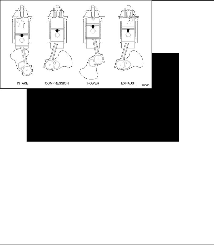
THE FOUR CYCLE PRINCIPLE FOR DIESEL ENGINES
The diesel engine is an internal combustion engine, in which the energy of burning fuel is converted into energy to work the cylinder of the engine. In the diesel engine, air alone is compressed in the cylinder, raising its temperature significantly. After the air has been
compressed, a charge of fuel is sprayed into the cylinder and ignition is accomplished by the heat of compression. The four piston strokes of the cycle occur in the following order: intake, compression, power and exhaust. See Figure 1.
Figure 1 The Four Stroke Cycle (Diesel)
Intake Stroke
During the intake stroke, the piston travels downward, the intake valves are open, and the exhaust valves are closed. The down stroke of the piston facilitates air from the intake manifold to enter the cylinder through the open intake valve. The turbocharger, by increasing the air pressure in the engine intake manifold, assures a full charge of air is available for the cylinder.
The intake charge consists of air only with no fuel mixture.
4 |
(Rev. 2005) All information subject to change without notice. |
6SE483 0507 Copyright © 2005 DETROIT DIESEL CORPORATION |

SERIES 60 SERVICE MANUAL
Compression Stroke
At the end of the intake stroke, the intake valves close and the piston starts upward on the compression stroke. The exhaust valves remain closed.
At the end of the compression stroke, the air in the combustion chamber has been compressed by the piston to occupy a space about one-fifteenth as great in volume as it occupied at the beginning of the stroke. Thus, the compression ratio is 15:1.
Compressing the air into a small space causes the temperature of that air to rise. Near the end of the compression stroke, the pressure of the air above the piston is approximately 3445 to 4134 kPa (500 to 600 lb/in.2) and the temperature of that air is approximately 538°C (1000°F). During the last part of the compression stroke and the early part of the power stroke, a small metered charge of fuel is injected into the combustion chamber.
Almost immediately after the fuel charge is injected into the combustion chamber, the fuel is ignited by the hot air and starts to burn, beginning the power stroke.
Power Stroke
During the power stroke, the piston travels downward and all intake and exhaust valves are closed.
As the fuel is added and burns, the gases get hotter, the pressure increases, pushing the piston downward and adding to crankshaft rotation.
Exhaust Stroke
During the exhaust stroke, the intake valves are closed; the exhaust valves are open, and the piston is on its up stroke.
The burned gases are forced out of the combustion chamber through the open exhaust valve port by the upward travel of the piston.
From the preceding description, it is apparent that the proper operation of the engine depends upon the two separate functions: first, compression for ignition, and second, that fuel be measured and injected into the compressed air in the cylinder in the proper quantity and at the proper time.
All information subject to change without notice. (Rev. 2005) |
5 |
6SE483 0507 Copyright © 2005 DETROIT DIESEL CORPORATION |

SERIES 60 SERVICE MANUAL
FOUR CYCLE PRINCIPLE FOR NATURAL GAS ENGINES
This engine is a four cycle internal combustion engine, in which the energy of burning fuel is converted into energy to work the cylinder of the engine. However, unlike the diesel engine, a combustible air and fuel mixture is introduced to the cylinder during the intake stroke. Upon compression, the temperature of this mixture is increased to a temperature below its auto-ignition threshold. Combustion occurs through means of a spark plug which ignites the mixture.
See Figure 2 for the four stroke cycle utilized on the natural gas engine.
Figure 2 The Four Stroke Cycle (Series 60G Engine)
6 |
(Rev. 2005) All information subject to change without notice. |
6SE483 0507 Copyright © 2005 DETROIT DIESEL CORPORATION |

SERIES 60 SERVICE MANUAL
Intake Stroke
During the intake stroke, the piston travels downward, the intake valves are open, and the exhaust valve are closed. The downward stroke of the piston increases the volume in the cylinder and draws in a fresh air and fuel mixture through the intake valves.
Compression Stroke
At the end of the intake stroke, the intake valves close and the piston starts upward on the compression stroke. The exhaust valves remain closed.
At the end of the compression stroke, the air-fuel mixture in the combustion chamber has been compressed by the piston to occupy a space about one-tenth as great in volume as it occupied at the beginning the stroke. Thus, the compression ratio is 10:1. This act of compression dramatically increases the temperature of the air-fuel mixture, to a temperature below its auto-ignition threshold. It is a timed, externally supplied ignition through the spark plug that
actually causes ignition to the mixture. The timed spark is introduced to the cylinder near the end of the compression stroke, which initiates combustion and begins the power stroke.
Power Stroke
During the power stroke, the piston travels downward and all intake and exhaust valves are closed.
As the throttle is opened to introduce a greater charge of air-fuel mixture to the cylinders, the increasing pressure of combustion against the pistons adds to crankshaft rotation.
Exhaust Stroke
During the exhaust stroke, the intake valves are closed, the exhaust valves are open, and the piston is on its up stroke.
The burning gases are forced out of the combustion chamber through the open exhaust valve port by the upward travel of the piston.
All information subject to change without notice. (Rev. 2005) |
7 |
6SE483 0507 Copyright © 2005 DETROIT DIESEL CORPORATION |

SERIES 60 SERVICE MANUAL
GENERAL DESCRIPTION
The Series 60® Diesel Engine described in this manual is a four-stroke cycle, high speed, diesel engine.
It uses an inline cast iron block and has a cast iron cylinder head that contains a single overhead camshaft. The camshaft actuates all the valves (two intake, two exhaust per cylinder), and operates the fuel injectors. The vertically aligned gear train, located at the front end of the engine in a gear case, contains drive gears for the lubricating oil pump, crankshaft, camshaft, air compressor drive, fuel pump drive, water pump and alternator accessory drives.
Each current engine is equipped with dual full-flow oil filters, an oil cooler, one or two fuel oil filters, a turbocharger and an electronic engine control system.
Full pressure lubrication is supplied to all main, connecting, camshaft and rocker assembly bearings and to other moving parts. A gear-type pump draws oil from the oil pan through a screen and delivers it to the oil filters. From the filter, a small portion of the oil is delivered directly
to the turbocharger by an external oil line. The remainder of the oil flows to the oil cooler, or bypasses the cooler, and then enters a longitudinal oil gallery in the cylinder block where the supply divides. Part of the oil goes to the cylinder head where it feeds the camshaft bearings and rocker assemblies. The remainder of the oil goes to the main bearings and connecting rod bearings via the drilled oil passages in the crankshaft. Drilled passages in the connecting rod feed oil to the piston pin and the inner surface of the piston crown.
Coolant is circulated through the engine by a centrifugal-type water pump. The cooling system, including the radiator, is a closed system. Heat is removed from the coolant by the radiator. Control of the engine temperature is accomplished by thermostats that regulate the flow of the coolant within the cooling system.
Fuel is drawn from the supply tank through the primary fuel filter by a gear-type fuel pump. From there, the fuel is forced through the secondary fuel filter and into the fuel inlet in the cylinder head and to the injectors. Excess fuel is returned, through a restricted fitting, to the supply tank through the outlet connecting line. Since the fuel is constantly circulating through the injectors, it serves to cool the injectors and to carry off any air in the fuel system. Air separators are available, as optional equipment.
Air is supplied by the turbocharger to the intake manifold and into the engine cylinders after passing through an air-to-air charge air cooler mounted ahead of the cooling system radiator. The charge air cooler cools the pressurized intake air charge coming from the turbocharger before it enters the intake manifold.
Engine starting may be provided by an electric or air starting motor energized by a storage battery or air pressure storage system. A battery charging alternator, with a suitable voltage regulator, serves to keep the battery charged.
The Series 60 diesel engine was designed to be electronically controlled. The Detroit Diesel Electronic Control (DDEC) system has evolved with the product.
8 |
(Rev. 2005) All information subject to change without notice. |
6SE483 0507 Copyright © 2005 DETROIT DIESEL CORPORATION |
SERIES 60 SERVICE MANUAL
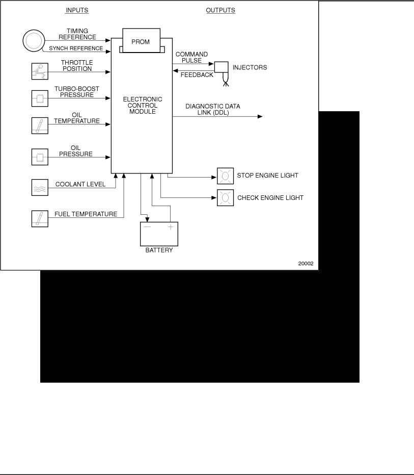
DDEC I
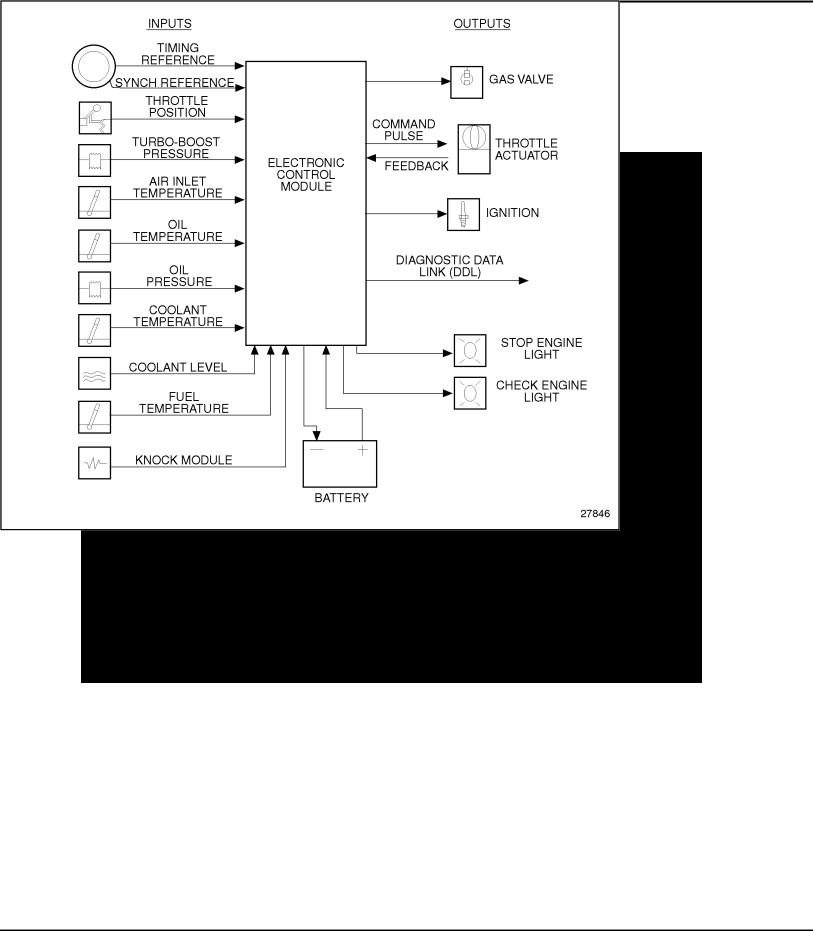
DDEC I controls the timing and amount of fuel injected into each cylinder. The system also monitors several engine functions using various sensors that send electrical signals to the main Electronic Control Module (ECM). See Figure 3. The ECM uses this information to send a command pulse to the Electronic Distributor Unit (EDU). The EDU functions as the high current switching unit for actuation of the Electronic Unit Injector (EUI) solenoids. The ECM also has the ability to limit or shut down the engine completely (depending on option selection) in the case of damaging engine conditions, such as low oil pressure, low coolant level, or high oil temperature.
Figure 3 Schematic Diagram of DDEC I
All information subject to change without notice. (Rev. 2005) |
9 |
6SE483 0507 Copyright © 2005 DETROIT DIESEL CORPORATION |
SERIES 60 SERVICE MANUAL
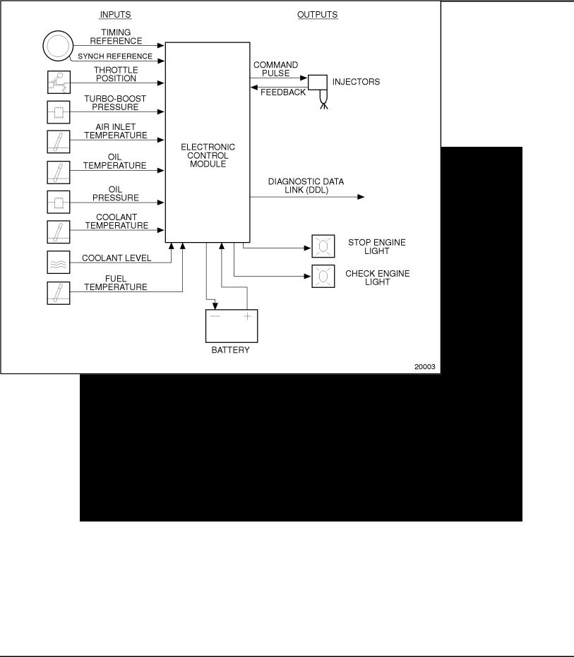
DDEC II
DDEC II also controls the timing and amount of fuel injected into each cylinder. The system also monitors several engine sensors that send electrical signals to the main ECM. See Figure 4. Unlike DDEC I, the DDEC II ECM uses this information to actuate the EUI solenoids. DDEC II incorporates all of the control electronics into one engine mounted ECM instead of the ECM and EDU that are required in DDEC I. The ECM also has the ability to limit or shut down the engine completely (depending on option selection) in the case of damaging engine conditions, such as low oil pressure, low coolant level, or high oil temperature.
Figure 4 Schematic Diagram of DDEC II
10 |
(Rev. 2005) All information subject to change without notice. |
6SE483 0507 Copyright © 2005 DETROIT DIESEL CORPORATION |
SERIES 60 SERVICE MANUAL
DDEC III/IV
The DDEC III/IV ECM receives electronic inputs from sensors on the engine and vehicle, and uses the information to control engine operation. It computes fuel timing and fuel quantity based upon predetermined calibration tables in its memory.
Fuel is delivered to the cylinders by the EUIs, which are cam-driven to provide the mechanical input for pressurization of the fuel. The ECM controls solenoid operated valves in the EUIs to provide precise fuel delivery. See Figure 5.
Figure 5 Schematic Diagram of DDEC III/IV
Portable equipment facilitates access to diagnostic capabilities of DDEC III/IV's. The Diagnostic Data Reader (DDR) requests and receives engine data and diagnostic codes. This equipment provides many unique capabilities including cylinder cutout, printer output, and data snapshot. The DDR also provides limited programming capability.
All information subject to change without notice. (Rev. 2005) |
11 |
6SE483 0507 Copyright © 2005 DETROIT DIESEL CORPORATION |
SERIES 60 SERVICE MANUAL
DDEC III/IV (Series 60G Engine)
The DDEC III/IV ECM receives electronic inputs from sensors on the engine and vehicle, and uses the information to control engine operation.
Fuel is controlled by DDEC. See Figure 6.
Figure 6 Schematic Diagram of DDEC III/IV (Series 60G Engine)
Portable equipment facilitates access to diagnostic capabilities of DDEC III/IV's. The Diagnostic Data Reader (DDR) requests and receives engine data and diagnostic codes. This equipment provides many unique capabilities including cylinder cutout, printer output, and data snapshot. The DDR also provides limited programming capability.
12 |
(Rev. 2005) All information subject to change without notice. |
6SE483 0507 Copyright © 2005 DETROIT DIESEL CORPORATION |

SERIES 60 SERVICE MANUAL
DDEC V
The DDEC V ECU receives electronic inputs from sensors on the engine and vehicle, and uses the information to control engine operation. It computes fuel timing and fuel quantity based upon predetermined calibration tables in its memory. DDEC V provides an indication of engine and vehicle malfunctions. The ECU continually monitors the DDEC V system. See Figure 7.
Figure 7 Schematic Diagram of DDEC V
Any faults that occur are stored as codes in the ECU's memory. A DDDL® can be used to read the codes.
All information subject to change without notice. (Rev. 2005) |
13 |
6SE483 0507 Copyright © 2005 DETROIT DIESEL CORPORATION |
SERIES 60 SERVICE MANUAL
GENERAL SPECIFICATIONS
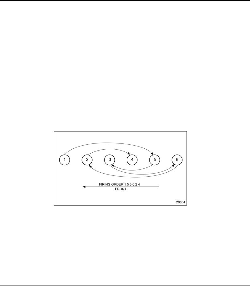
The general specifications for the Series 60 Engine are listed in Table 1. See Figure 8 for the cylinder designation and firing order.
General Specifications |
11.1L Family |
12.7L Family |
14L Family |
|
|
|
|
Total Displacement (L) |
11.1 |
12.7 |
14.0 |
|
|
|
|
Total Displacement (in.3) |
677 |
775 |
855 |
Type |
4-cycle |
4-cycle |
4-cycle |
|
|
|
|
Number of Cylinders |
6 |
6 |
6 |
|
|
|
|
Bore (in.) |
5.12 |
5.12 |
5.24 |
|
|
|
|
Bore (mm) |
130 |
130 |
133 |
|
|
|
|
Stroke (in.) |
5.47 |
6.30 |
6.61 |
|
|
|
|
Stroke (mm) |
139 |
160 |
168 |
|
|
|
|
Compression Ratio |
16.0:1 |
15.0:1 or 16.5:1 |
15.0:1 or 16.5:1 |
|
|
|
|
Number of Main Bearings |
7 |
7 |
7 |
|
|
|
|
Table 1 Specifications for the Series 60 Engine
Figure 8 Cylinder Designation and Firing Order
14 |
(Rev. 2005) All information subject to change without notice. |
6SE483 0507 Copyright © 2005 DETROIT DIESEL CORPORATION |
SERIES 60 SERVICE MANUAL
GENERAL SPECIFICATIONS FOR THE SERIES 60G ENGINE
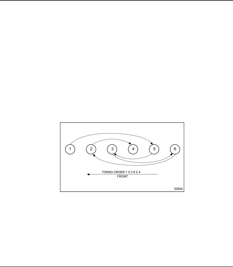
The general specifications for the Series 60G Engine are listed in Table 2. See Figure 9 for cylinder designation and firing order.
General Description |
Specification |
|
|
Total Displacement (L) |
12.7 |
|
|
Total Displacement (in.3) |
775 |
Type |
Four-cycle |
|
|
Number of Cylinders |
6 |
|
|
Bore (in.) |
5.12 |
|
|
Bore (mm) |
130 |
|
|
Stroke (in.) |
6.30 |
|
|
Stroke (mm) |
160 |
|
|
Compression Ratio |
10:1 |
|
|
Number of Main Bearings |
7 |
|
|
Table 2 General Specifications for the Series 60G Engine
Figure 9 Cylinder Designation and Firing Order for the Series 60G Engine
All information subject to change without notice. (Rev. 2005) |
15 |
6SE483 0507 Copyright © 2005 DETROIT DIESEL CORPORATION |
SERIES 60 SERVICE MANUAL
ENGINE MODEL, SERIAL NUMBER AND OPTION LABEL
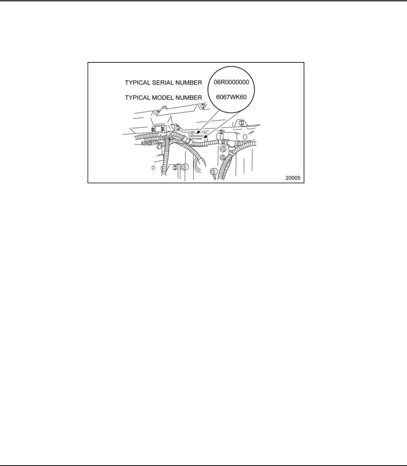
The engine serial and model numbers are stamped on the cylinder block. See Figure 10. A guide to the meaning of the model number digits is listed in Table 3.
Figure 10 Location of Engine Serial and Model Number on Block
16 |
(Rev. 2005) All information subject to change without notice. |
6SE483 0507 Copyright © 2005 DETROIT DIESEL CORPORATION |

|
|
|
|
SERIES 60 SERVICE MANUAL |
|
|
|
|
|
|
|
|
|
|
|
|
|
|
Digit |
Value |
Meaning |
|
|
|
|
|
|
|
|
|
|
1 |
6 |
Series 60 Engine |
|
|
|
|
|
|
|
|
2 |
& 3 |
06 |
Six Cylinders |
|
|
|
|
|
|
|
|
|
4 |
7 |
Automotive Application |
|
|
|
|
|
|
|
|
|
5 |
W, S, E, L |
11.1 L Displacement |
|
|
|
|
|
|
|
|
|
5 |
G, T, M |
12.7 L - Standard |
|
|
|
|
|
|
|
|
|
5 |
P, B |
12.7 L - Premium |
|
|
|
|
|
|
|
|
|
5 |
F, H |
14 L Displacement |
|
|
|
|
|
|
|
|
|
6 |
T |
DDEC I Engine Control |
|
|
|
|
|
|
|
|
|
6 |
U |
DDEC II Engine Control |
|
|
|
|
|
|
|
|
|
6 |
K |
DDEC III/IV Engine Control |
|
|
|
|
|
|
|
|
|
6 |
V |
DDEC V Engine Control |
|
|
|
|
|
|
|
|
7 |
& 8 |
28 |
1991 and later Coach |
|
|
|
|
|
|
|
|
7 |
& 8 |
40 |
Pre-1991 Engine |
|
|
|
|
|
|
|
|
7 |
& 8 |
60 |
1991 and later On-Highway Truck |
|
|
|
|
|
|
|
Table 3 Model Number Description for Series 60 Engine
For example, 6067-WK60 represents an 11.1 liter Series 60 engine that is controlled with DDEC III/IV electronics to be used in a 1991 or later truck.
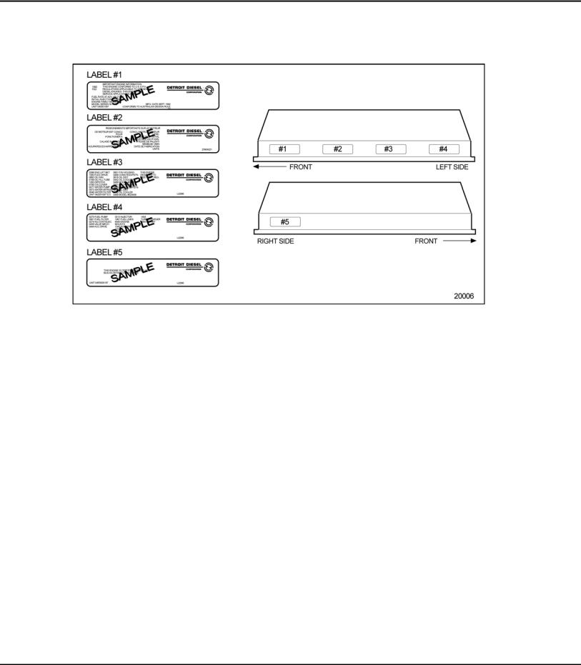
Option labels attached to the valve rocker cover contain the engine serial and model numbers and list any optional equipment used on the engine. See Figure 11.
With any order for parts, the engine model number with serial number should be given. In addition, if a type number is shown on the option plate covering the equipment required, this number should also be included on the parts order.
All information subject to change without notice. (Rev. 2005) |
17 |
6SE483 0507 Copyright © 2005 DETROIT DIESEL CORPORATION |
SERIES 60 SERVICE MANUAL
All groups or parts used on a unit are standard for the engine model unless otherwise listed on the option plate.
Figure 11 Rocker Cover with Option Label
18 |
(Rev. 2005) All information subject to change without notice. |
6SE483 0507 Copyright © 2005 DETROIT DIESEL CORPORATION |
 Loading...