

Page 1

AV SURROUND RECEIVER
CH SEL
ENTER
RC-970
AVR-3805
OPERATING INSTRUCTIONS
BEDIENUNGSANLEITUNG
MODE D’EMPLOI
ISTRUZIONI PER L’USO
INSTRUCCIONES DE OPERACION
GEBRUIKSAANWIJZING
BRUKSANVISNING
FOR ENGLISH READERS PAGE 112 ~ PAGE 163
FÜR DEUTSCHE LESER SEITE 164 ~ SEITE 124
POUR LES LECTEURS FRANCAIS PAGE 125 ~ PAGE 185
PER IL LETTORE ITALIANO PAGINA 186 ~ PAGINA 246
PARA LECTORES DE ESPAÑOL PAGINA 247 ~ PAGINA 307
VOOR NEDERLANDSTALIGE LEZERS PAGINA 308 ~ PAGINA 368
FOR SVENSKA LÄSARE SIDA 369 ~ SIDA 429
Page 2
ENGLISH DEUTSCH FRANCAIS ITALIANO ESPAÑOL NEDERLANDS SVENSKA
NOTE ON USE / HINWEISE ZUM GEBRAUCH /
OBSERVATIONS RELATIVES A L’UTILISATION / NOTE SULL’USO
CAUTION
NOTAS SOBRE EL USO / ALVORENS TE GEBRUIKEN / OBSERVERA
RISK OF ELECTRIC SHOCK
DO NOT OPEN
CAUTION: TO REDUCE THE RISK OF ELECTRIC SHOCK, DO
NOT REMOVE COVER (OR BACK). NO USER
SERVICEABLE PARTS INSIDE. REFER SERVICING
TO QUALIFIED SERVICE PERSONNEL.
The lightning flash with arrowhead symbol, within an equilateral triangle,
is intended to alert the user to the presence of uninsulated “dangerous
voltage” within the product’s enclosure that may be of sufficient
magnitude to constitute a risk of electric shock to persons.
The exclamation point within an equilateral triangle is intended to alert the
user to the presence of important operating and maintenance (servicing)
instructions in the literature accompanying the appliance.
WARNING: TO REDUCE THE RISK OF FIRE OR ELECTRIC SHOCK, DO
NOT EXPOSE THIS APPLIANCE TO RAIN OR MOISTURE.
• DECLARATION OF CONFORMITY
We declare under our sole responsibility that this
product, to which this declaration relates, is in conformity
with the following standards:
EN60065, EN55013, EN55020, EN61000-3-2 and
EN61000-3-3.
Following the provisions of 73/23/EEC, 89/336/EEC and
93/68/EEC Directive.
• ÜBEREINSTIMMUNGSERKLÄRUNG
Wir erklären unter unserer Verantwortung, daß dieses
Produkt, auf das sich diese Erklärung bezieht, den
folgenden Standards entspricht:
EN60065, EN55013, EN55020, EN61000-3-2 und
EN61000-3-3.
Entspricht den Verordnungen der Direktive 73/23/EEC,
89/336/EEC und 93/68/EEC.
• DECLARATION DE CONFORMITE
Nous déclarons sous notre seule responsabilité que
l’appareil, auquel se réfère cette déclaration, est
conforme aux standards suivants:
EN60065, EN55013, EN55020, EN61000-3-2 et
EN61000-3-3.
D’après les dispositions de la Directive 73/23/EEC,
89/336/EEC et 93/68/EEC.
• DICHIARAZIONE DI CONFORMITÀ
Dichiariamo con piena responsabilità che questo
prodotto, al quale la nostra dichiarazione si riferisce, è
conforme alle seguenti normative:
EN60065, EN55013, EN55020, EN61000-3-2 e EN610003-3.
In conformità con le condizioni delle direttive 73/23/EEC,
89/336/EEC e 93/68/EEC.
QUESTO PRODOTTO E’ CONFORME
AL D.M. 28/08/95 N. 548
• DECLARACIÓN DE CONFORMIDAD
Declaramos bajo nuestra exclusiva responsabilidad que
este producto al que hace referencia esta declaración,
está conforme con los siguientes estándares:
EN60065, EN55013, EN55020, EN61000-3-2 y EN610003-3.
Siguiendo las provisiones de las Directivas 73/23/EEC,
89/336/EEC y 93/68/EEC.
• EENVORMIGHEIDSVERKLARING
Wij verklaren uitsluitend op onze verantwoordelijkheid
dat dit produkt, waarop deze verklaring betrekking heeft,
in overeenstemming is met de volgende normen:
EN60065, EN55013, EN55020, EN61000-3-2 en
EN61000-3-3.
Volgens de bepalingen van de Richtlijnen 73/23/EEC,
89/336/EEC en 93/68/EEC.
• ÖVERENSSTÄMMELSESINTYG
Härmed intygas helt på eget ansvar att denna produkt,
vilken detta intyg avser, uppfyller följande standarder:
EN60065, EN55013, EN55020, EN61000-3-2 och
EN61000-3-3.
Enligt stadgarna i direktiv 73/23/EEC, 89/336/EEC och
93/68/EEC.
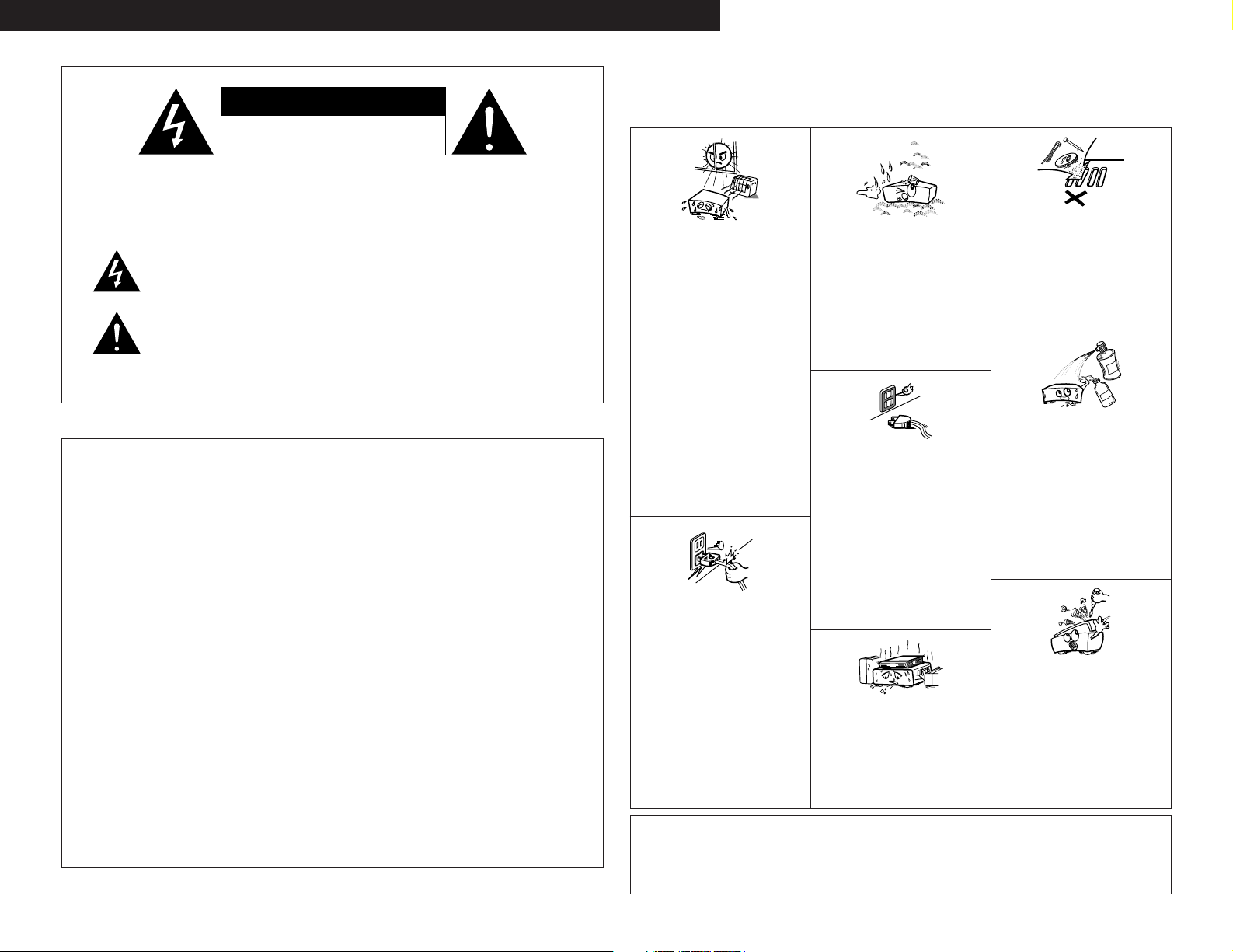
• Keep the set free from moisture, water, and
• Avoid high temperatures.
Allow for sufficient heat dispersion when
installed on a rack.
• Vermeiden Sie hohe Temperaturen.
Beachten Sie, daß eine ausreichend
Luftzirkulation gewährleistet wird, wenn das
Gerät auf ein Regal gestellt wird.
• Eviter des températures élevées
Tenir compte d’une dispersion de chaleur
suffisante lors de l’installation sur une
étagère.
• Evitate di esporre l’unità a temperature alte.
Assicuratevi che ci sia un’adeguata
dispersione del calore quando installate
l’unità in un mobile per componenti audio.
• Evite altas temperaturas
Permite la suficiente dispersión del calor
cuando está instalado en la consola.
• Vermijd hoge temperaturen.
Zorg voor een degelijk hitteafvoer indien het
apparaat op een rek wordt geplaatst.
• Undvik höga temperaturer.
Se till att det finns möjlighet till god
värmeavledning vid montering i ett rack.
• Handle the power cord carefully.
Hold the plug when unplugging the cord.
• Gehen Sie vorsichtig mit dem Netzkabel um.
Halten Sie das Kabel am Stecker, wenn Sie
den Stecker herausziehen.
• Manipuler le cordon d’alimentation avec
précaution.
Tenir la prise lors du débranchement du
cordon.
• Manneggiate il filo di alimentazione con cura.
Agite per la spina quando scollegate il cavo
dalla presa.
• Maneje el cordón de energía con cuidado.
Sostenga el enchufe cuando desconecte el
cordón de energía.
• Hanteer het netsnoer voorzichtig.
Houd het snoer bij de stekker vast wanneer
deze moet worden aan- of losgekoppeld.
• Hantera nätkabeln varsamt.
Håll i kabeln när den kopplas från el-uttaget.
CAUTION
• The ventilation should not be impeded by covering the
ventilation openings with items, such as newspapers,
table-cloths, curtains, etc.
• No naked flame sources, such as lighted candles, should
be placed on the apparatus.
dust.
• Halten Sie das Gerät von Feuchtigkeit,
Wasser und Staub fern.
• Protéger l’appareil contre l’humidité, l’eau et
lapoussière.
• Tenete l’unità lontana dall’umidità, dall’acqua
e dalla polvere.
• Mantenga el equipo libre de humedad, agua
y polvo.
• Laat geen vochtigheid, water of stof in het
apparaat binnendringen.
• Utsätt inte apparaten för fukt, vatten och
damm.
• Unplug the power cord when not using the
set for long periods of time.
• Wenn das Gerät eine längere Zeit nicht
verwendet werden soll, trennen Sie das
Netzkabel vom Netzstecker.
• Débrancher le cordon d’alimentation lorsque
l’appareil n’est pas utilisé pendant de
longues périodes.
• Disinnestate il filo di alimentazione quando
avete l’intenzione di non usare il filo di
alimentazione per un lungo periodo di tempo.
• Desconecte el cordón de energía cuando no
utilice el equipo por mucho tiempo.
• Neem altijd het netsnoer uit het stopkontakt
wanneer het apparaat gedurende een lange
periode niet wordt gebruikt.
• Koppla ur nätkabeln om apparaten inte
kommer att användas i lång tid.
* (For sets with ventilation holes)
• Do not obstruct the ventilation holes.
• Die Belüftungsöffnungen dürfen nicht
verdeckt werden.
• Ne pas obstruer les trous d’aération.
• Non coprite i fori di ventilazione.
• No obstruya los orificios de ventilación.
• De ventilatieopeningen mogen niet worden
beblokkeerd.
• Täpp inte till ventilationsöppningarna.
• Do not let foreign objects in the set.
• Keine fremden Gegenstände in das Gerät
kommen lassen.
• Ne pas laisser des objets étrangers dans
l’appareil.
• E’ importante che nessun oggetto è inserito
all’interno dell’unità.
• No deje objetos extraños dentro del equipo.
• Laat geen vreemde voorwerpen in dit
apparaat vallen.
• Se till att främmande föremål inte tränger in i
apparaten.
• Do not let insecticides, benzene, and thinner
come in contact with the set.
• Lassen Sie das Gerät nicht mit Insektiziden,
Benzin oder Verdünnungsmitteln in
Berührung kommen.
• Ne pas mettre en contact des insecticides,
du benzène et un diluant avec l’appareil.
• Assicuratevvi che l’unità non venga in
contatto con insetticidi, benzolo o solventi.
• No permita el contacto de insecticidas,
gasolina y diluyentes con el equipo.
• Laat geen insektenverdelgende middelen,
benzine of verfverdunner met dit apparaat in
kontakt komen.
• Se till att inte insektsmedel på spraybruk,
bensen och thinner kommer i kontakt med
apparatens hölje.
• Never disassemble or modify the set in any
way.
• Versuchen Sie niemals das Gerät
auseinander zu nehmen oder auf jegliche Art
zu verändern.
• Ne jamais démonter ou modifier l’appareil
d’une manière ou d’une autre.
• Non smontate mai, nè modificate l’unità in
nessun modo.
• Nunca desarme o modifique el equipo de
ninguna manera.
• Nooit dit apparaat demonteren of op andere
wijze modifiëren.
• Ta inte isär apparaten och försök inte bygga
om den.
• Please be care the environmental aspects of battery
disposal.
• The apparatus shall not be exposed to dripping or
splashing for use.
• No objects filled with liquids, such as vases, shall be
placed on the apparatus.
2
Page 3
ENGLISH
CH SEL
ENTER
2 We greatly appreciate your purchase of the AVR-3805.
2 To be sure you take maximum advantage of all the features the AVR-3805 has to offer, read these
instructions carefully and use the set properly. Be sure to keep this manual for future reference,
should any questions or problems arise.
“SERIAL NO.
PLEASE RECORD UNIT SERIAL NUMBER ATTACHED TO THE REAR OF THE
CABINET FOR FUTURE REFERENCE”
2 INTRODUCTION
Thank you for choosing the DENON AVR-3805 Digital A / V Surround Receiver. This remarkable component has
been engineered to provide superb surround sound listening with home theater sources such as DVD, as well as
providing outstanding high fidelity reproduction of your favorite music sources.
As this product is provided with an immense array of features, we recommend that before you begin hookup and
operation that you review the contents of this manual before proceeding.
TABLE OF CONTENTS
Before Using........................................................3
z
Cautions on Installation........................................3
x
Cautions on Handling...........................................3
c
Features...............................................................4
v
Connections.....................................................5~9
b
Part Names and Functions ..........................10, 11
n
Setting up the System ................................11~29
m
Remote Control Unit ...................................30~35
,
Operation.....................................................36~39
.
2
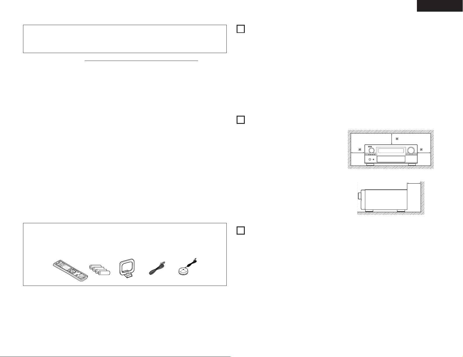
ACCESSORIES
Check that the following parts are included in addition to the main unit:
Multi Zone....................................................40, 41
⁄0
Surround......................................................41~46
⁄1
DSP Surround Simulation............................47~50
⁄2
Listening to the Radio .................................50~54
⁄3
Last Function Memory.......................................54
⁄4
Initialization of the Microprocessor....................54
⁄5
Troubleshooting ...........................................54, 55
⁄6
Additional Information .................................55~62
⁄7
Specifications.....................................................63
⁄8
1
BEFORE USING
Pay attention to the following before using this unit:
• Moving the set
To prevent short circuits or damaged wires in the
connection cords, always unplug the power cord
and disconnect the connection cords between all
other audio components when moving the set.
• Before turning the power switch on
Check once again that all connections are proper
and that there are not problems with the connection
cords. Always set the power switch to the standby
position before connecting and disconnecting
connection cords.
2
CAUTIONS ON INSTALLATION
Noise or disturbance of the picture may be generated
if this unit or any other electronic equipment using
microprocessors is used near a tuner or TV.
If this happens, take the following steps:
• Install this unit as far as possible from the tuner or
TV.
• Set the antenna wires from the tuner or TV away
from this unit’s power cord and input/output
connection cords.
• Noise or disturbance tends to occur particularly
when using indoor antennas or 300 Ω/ohms feeder
wires. We recommend using outdoor antennas
and 75 Ω/ohms coaxial cables.
For heat dispersal, leave at least 10 cm of space
between the top, back and sides of this unit and
the wall or other components.
• Store this instructions in a safe place.
After reading, store this instructions along with the
warranty in a safe place.
• Note that the illustrations in this instructions
may differ from the actual set for explanation
purposes.
10 cm or more
10 cm or more
Wall
q Operating instructions........................................1
w Service station list..............................................1
e Remote control unit (RC-970) ............................1
ertyu
70
9
C
R
r R03/AAA batteries .............................................4
t AM loop antenna................................................1
y FM indoor antenna.............................................1
u Omnidirectional microphone..............................1
3
CAUTIONS ON HANDLING
• Switching the input function when input jacks
are not connected
A clicking noise may be produced if the input
function is switched when nothing is connected to
the input jacks. If this happens, either turn down the
MASTER VOLUME control or connect components
to the input jacks.
• Muting of PRE OUT jacks, HEADPHONE jack and
SPEAKER terminals
The PRE OUT jacks, HEADPHONE jack and
SPEAKER terminals include a muting circuit.
Because of this, the output signals are greatly
reduced for several seconds after the power switch
is turned on or input function, surround mode or any
other-set-up is changed. If the volume is turned up
during this time, the output will be very high after
the muting circuit stops functioning. Always wait
until the muting circuit turns off before adjusting the
volume.
• Whenever the unit is in the STANDBY state, the
apparatus is still connected on AC line voltage.
Please be sure to turn the power off (
when you leave home for, say, a vacation.
£off)
3
Page 4

ENGLISH
4
FEATURES
1. Dolby Digital
Using advanced digital processing algorithms,
Dolby Digital provides up to 5.1 channels of widerange, high fidelity surround sound. Dolby Digital
is the default digital audio delivery system for DVD
and North American DTV.
2. Dolby Pro Logic IIx compatibility
Dolby Pro Logic IIx furthers the matrix decording
technology of Dolby Pro Logic II to decode audio
signals recorded on two channels into up to 7.1
playback channels, including the surround back
channel. Dolby Pro Logic IIx also allows 5.1channel sources to be played in up to 7.1
channels.
The mode can be selected according to the
source. The Music mode is best suited for playing
music,the Cinema mode for playing movies, and
the Game mode for playing games. The Game
mode can only be used with 2-channel audio
sources.
3. Dolby Pro Logic II Game mode compatibility
In addition to the previously offered Music and
Cinema modes, the AVR-3805 also offers a Game
mode optimum for games.
4. DTS (Digital Theater Systems)
DTS provides up to 5.1 channels of wide-range,
high fidelity surround sound, from sources such as
laser disc, DVD and specially-encoded music
discs.
5. DTS-ES Extended Surround and DTS Neo:6
The AVR-3805 can be decoded with DTS-ES
Extended Surround, a multi-channel format
developed by Digital Theater Systems Inc.
The AVR-3805 can be also decoded with DTS
Neo:6, a surround mode allowing 6.1 channels
playback of regular stereo sources.
6. DTS 96/24 compatibility
The AVR-3805 can be decoded with sources
recorded in DTS 96/24, a multi-channel digital
signal format developed by Digital Theater
Systems Inc.
DTS 96/24 sources can be played in the multichannel mode on the AVR-3805 with high sound
quality of 96 kHz/24 bits or 88.2 kHz/24 bits.
7. HDCD decoder equipped
Connection with a player that supports HDCD
playback allows the features of HDCD to be
extracted, namely the characteristics of high
resolution and low distortion, and fusion with the
digital technology that is contained in the AVR3805 allows for the exhibition of the high sound
quality of HDCD.
8. DENON LINK
The connection of one cable to our DVD player,
which supports digital transfer, permits the digital
transfer of DVD audio, and DVD multi-channel
audio for an enjoyable experience of higher sound
quality digital sound with low transfer losses.
9. NEW D.D.S.C-Digital
New 32-bit floating point DSP is used for digital
transfer processing. Furthermore, operation of
D/A and DIR at up to 192 kHz supports the digital
transfer of DVD audio by DENON LINK.
10. AL24 Processing for All Channels
DENON has further developed its proprietary
AL24 Processing, an analog waveform
reproduction technology, to support the 192-kHz
sampling frequency of DVD-Audio, AL24
Processing Plus, thoroughly suppresses
quantization noise associated with D/A conversion
of LPCM signals to reproduce the low-level
signals with optimum clarity that will bring out all
the delicate nuances of the signals with optimum
clarity that will bring out all the delicate nuances of
the music.
Equipped for not only the front left and right
channels but also for the surround left and right,
center and subwoofer channels.
11. Auto Setup/Room EQ
Use of the microphone for setup applications
measures the presence of speakers, the distance
to the speakers, and other information, and
permits automatic setup. The characteristics of
each speaker can also be corrected.
Auto setup requires a microphone for setup use.
12. Dual Surround Speaker Mode
Provides for the first time the ability to optimize
surround sound reproduction using two different
types of surround sound speakers as well as two
different surround speaker positions:
(1) Movie Surround
Motion picture soundtracks use the surround
channel(s) to provide the ambient elements of
the acoustic environment they want the
audience to realize. This is best accomplished
by the use of specially-designed surround
speakers that offer a wide diffusion pattern
(bipolar dispersion) or by using surround
speakers that provide broad dispersion with a
minimum of on-axis localization (dipolar
dispersion). Side wall mounting (closer to the
ceiling) of the surround speakers provides the
greatest envelopment, minimizing localization
of direct sound from the speakers.
(2) Music Surround
With full range discrete surround channels, as
well as three discrete full range front channels,
digital formats such as Dolby and DTS offer
thrilling surround sound music listening.
Producers of multi-channel discrete digital
music recordings almost always favor the use
of direct radiating (monopolar) surround
speakers, placed in the rear corners of the
room, since that is how they configure their
studios during the mixing/creation process.
The DENON AVR-3805 provides the ability to
connect two different sets of surround speakers,
and place them in the appropriate locations in your
AV theater room, so that you can enjoy both movie
soundtracks and music listening, with optimum
results and no compromise.
13. Multi Zone Music Entertainment System
Multi Source Function:
This unit’s Multi Source function lets you select
different audio sources for listening Different
sources can thus be enjoyed in the main room
(MAIN) and the subroom (ZONE2 and ZONE3)
simultaneously.
14. Future Sound Format Upgrade Capability via
Eight Channel Inputs & Outputs
For future multi-channel audio format(s), the AVR3805 is provided with 7.1 channel (seven main
channels, plus one low frequency effects channel)
inputs, along with a full set of 7.1 channel pre-amp
outputs, controlled by the 8 channel master
volume control. This assures future upgrade
possibilities for any future multi-channel sound
format.
15. Front input Terminal
The unit is equipped with a Front Input connector
for the convenient connection of a video camera
or other equipment.
16. Video Conversion Function
The AVR-3805 is equipped with a function for upconverting video signals.
Because of this, the AVR-3805’s MONITOR OUT
jack can be connected to the monitor (TV) with a
set of cables offering a higher quality connection,
regardless of how the player and the AVR-3805’s
video input jacks are connected.
17. Component Video Switching
In addition to composite video and “S” video
switching, the AVR-3805 provides 3 sets of
component video (Y, P
set of component video outputs to the television,
for superior picture quality.
B/CB, PR/CR) inputs, and one
18. TRIGGER OUT
AVR-3805 is equipped with 2 systems of 12V
TRIGGER OUT connections. Each output can be
activated upon the selection of assigned. Main
Zone inputs or zone2 inputs or zone3 inputs.
19. RS-232C Terminal
Includes a RS--232C port to support an AMX,
Crestron integrated control system.
20. AC INLET
Detachable AC CORD is used.
21. Auto Surround Mode
This function stores the surround mode last used
for an input signal in the memory and
automatically sets that surround mode the next
time that signal is input.
22. EL Foil Remote
An EL Foil remote with improved operational
qualities is used which displays only the keys
required by the device.
23. Large-sized fluorescent display
A large-sized fluorescent display is used which
also permits a check of the input/output channels.
24. Audio delay
This is a function for delaying the audio signal with
respect to the video signal. (0 to 200 msec)
25. Preset Memory Tuning
56-Station AM/FM Random Preset Memory
tuning.
4
Page 5
ENGLISH
RLR
L
R
INPUT OUTPUT
LRL
R
OUTPUT
L
R
L
L
R
L
R
L
R
L
R
DIGITAL AUDIODIGITAL AUDIO
OUTPUT
OPTICAL COAXIAL
DIGITAL AUDIODIGITAL AUDIO
B
INPUT
OPTICAL
OUTPUT
B
IN
VIDEO
R
L
R OUT IN
AUDIO
VIDEO
OUT IN
LRL
RLR
L
R OUT IN
AUDIO
VIDEO
OUT IN
LRL
RLR
L
R OUT
VIDEO
OUT
L
AUDIO
L
R
R OUT
VIDEO
OUT
L
AUDIO
L
R
R
L
R
L
R
L
R L
B
B
RL
5
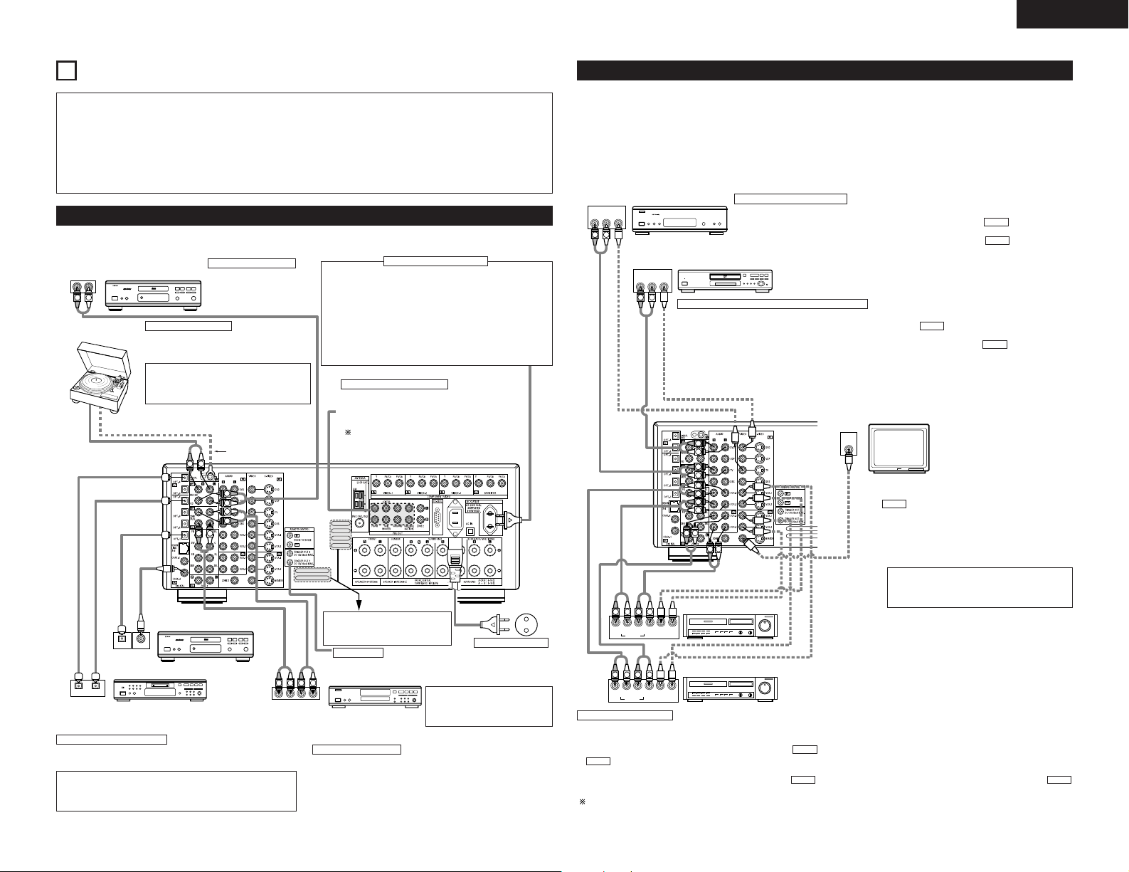
CONNECTIONS
Do not plug in the AC cord until all connections
•
have been completed.
Be sure to connect the left and right channels
•
properly (left with left, right with right).
Insert the plugs securely. Incomplete connections
•
will result in the generation of noise.
Use the AC OUTLET for audio equipment only.
•
Do not use them for hair driers, etc.
Note that binding pin plug cords together with AC
•
cords or placing them near a power transformer
will result in generating hum or other noise.
Noise or humming may be generated if a
•
connected audio equipment is used independently
without turning the power of this unit on. If this
happens, turn on the power of the this unit.
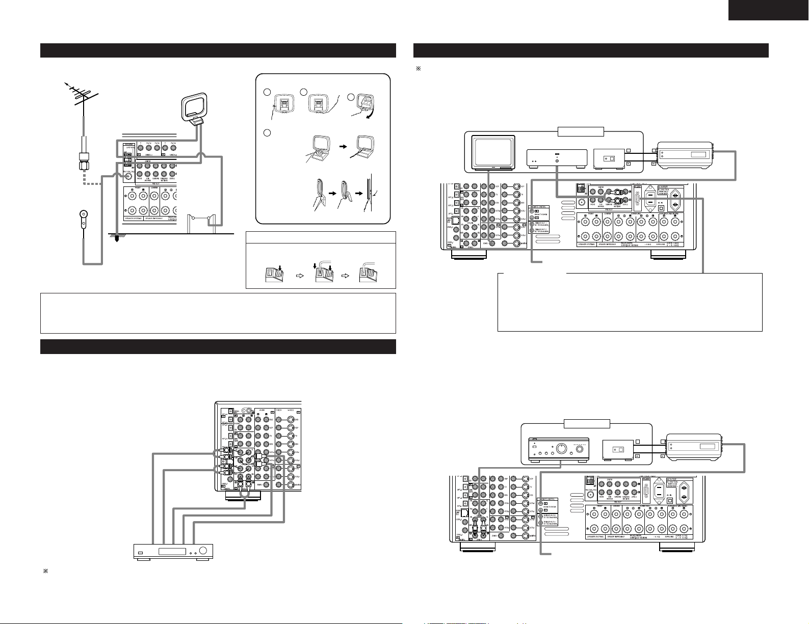
Connecting the audio components
• When making connections, also refer to the operating instructions of the other components.
CD player
Turntable
(MM cartridge)
Connecting a CD player
Connect the CD player’s analog
output jacks (ANALOG
OUTPUT) to this unit’s CD jacks
using pin plug cords.
Connecting a turntable
Connect the turntable’s output cord to the AVR3805’s PHONO jacks, the L (left) plug to the L jack,
the R (right) plug to the right jack.
NOTE:
This unit cannot be used with MC cartridges
directly. Use a separate head amplifier or step-up
transformer.
If humming or other noise is generated when the
ground wire is connected, disconnect the ground
wire.
Ground wire
AC OUTLET
• SWITCHED
(total capacity – 100 W)
The power to these outlets is turned on and off in conjunction with
the POWER operation switch on the main unit, and when the power
is switched between on and standby from the remote control unit.
No power is supplied from these outlets when this unit’s power is
at standby. Never connect equipment whose total capacity is above
100 W.
NOTE:
Only use the AC OUTLET for audio equipment. Never use them for
hair driers, TVs or other electrical appliances.
Connecting the pre-out jacks
Use these jacks if you wish to connect external power
amplifier(s) to increase the power of the front, center and
surround sound channels, or for connection to powered
loudspeakers.
To use Surround back with one speaker, connect the
speaker to SURR. BACK L CH.
Connecting the AC OUTLET
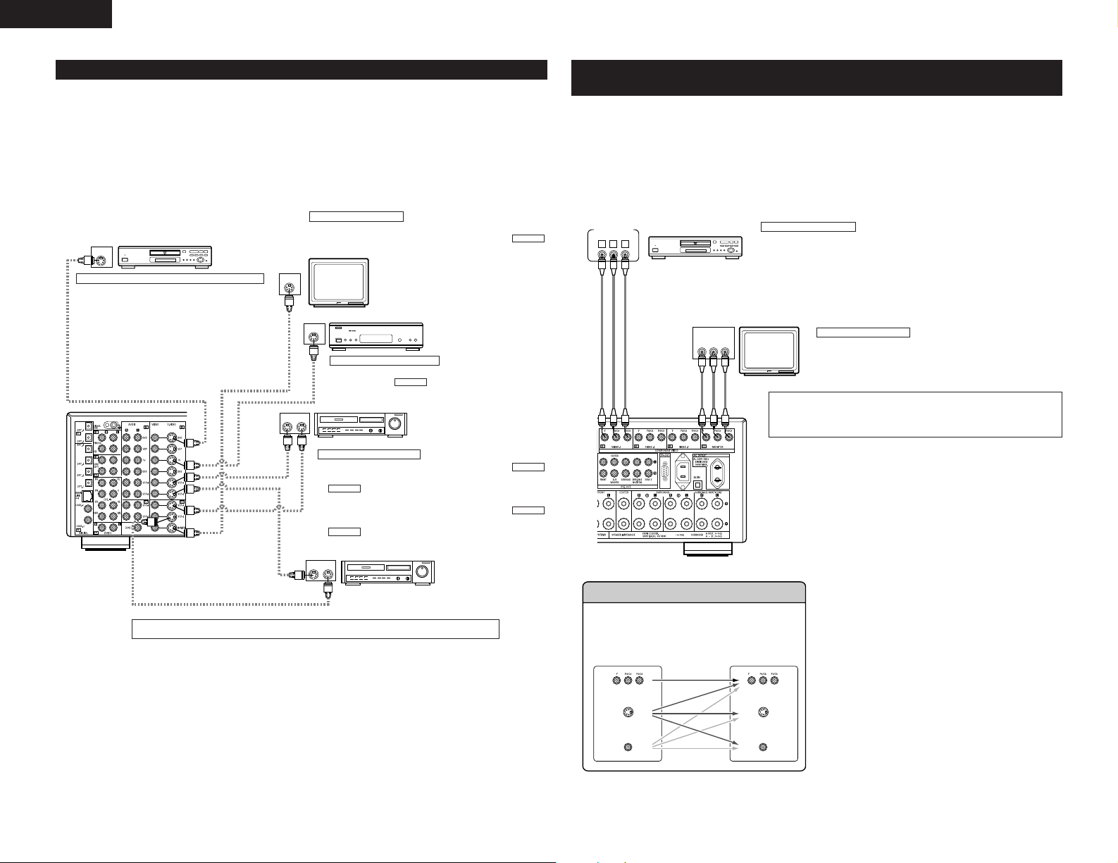
Connecting the video components
• To connect the video signal, connect using a 75 Ω/ohms video signal cable cord. Using an improper cable can
result in a drop in video quality.
• When making connections, also refer to the operating instructions of the other components.
• The AVR-3805 is equipped with a function for up-converting video signals.
• The signal connected to the video signal terminal is output to the S-Video and component video monitor out
terminals.
• The REC OUT terminals have no conversion function, so when recording only connect the video terminals.
TV or DBS tuner
Connecting a DVD player or a video disc player (VDP)
DVD
• Connect the video disc player’s video output jack (VIDEO OUTPUT) to the (yellow) DVD IN jack using a 75 Ω/ohms
video coaxial pin plug cord.
• Connect the video disc player’s analog audio output jacks (ANALOG AUDIO OUTPUT) to the DVD IN jacks using
pin plug cords.
• VDP can be connected to the VDP jacks in the same way.
Connecting a TV or DBS tuner
TV or DBS
• Connect the TV’s or DBS tuner’s video output jack (VIDEO OUTPUT) to the (yellow) TV or DBS
IN jack using a 75 Ω/ohms video coaxial pin plug cord.
• Connect the TV’s or DBS tuner’s audio output jacks (AUDIO OUTPUT) to the TV or DBS IN jacks
using pin plug cords.
VIDEO
AUDIO
DVD player or video disc player (VDP), etc.
VIDEO
AUDIO
Monitor TV
CD player or other component
equipped with digital output jacks
MD recorder, CD recorder or other component
equipped with digital input/output jacks
Connecting the DIGITAL jacks
Use these for connections to audio equipment with digital output. Refer
to “Setting the Digital in Assignment”. (See page 23)
NOTES:
• Use 75 Ω/ohms cable pin cords for coaxial connections.
• Use optical cables for optical connections, removing the cap before
connecting.
MONITOR OUT
• Connect the TV’s video input jack (VIDEO INPUT) to the
VIDEO
MONITOR OUT jack using a 75 Ω/ohms video
coaxial pin plug cord.
Video deck 2
Route the connection cords, etc., in
such a way that they do not obstruct
the ventilation holes.
TRIGGER OUT
Turn the DC 12V voltage on and off for the individual functions.
For details, see “Setting the Trigger Setup”. (See page 27)
NOTE:
If humming noise is generated by a
CD recorder or Tape deck
tape deck, etc., move the tape deck
away.
Connecting a tape deck
Connections for recording:
Connect the tape deck’s recording input jacks (LINE IN or REC) to this unit’s
tape recording (CDR/TAPE OUT) jacks using pin plug cords.
Connections for playback:
Connect the tape deck’s playback output jacks (LINE OUT or PB) to this
unit’s tape playback (CDR/TAPE IN) jacks using pin plug cords.
Power supply cord
AC 230V, 50Hz
Video deck 1
Connecting a video decks
• There are two sets of video deck (VCR) jacks, so two video decks can be connected for simultaneous recording or video copying.
Video input/output connections:
• Connect the video deck’s video output jack (VIDEO OUT) to the (yellow) VCR-1 IN jack, and the video deck’s video input jack (VIDEO IN) to the
VIDEO
(yellow) VCR-1 OUT jack using 75 Ω/ohms video coaxial pin plug cords.
Connecting the audio output jacks
• Connect the video deck’s audio output jacks (AUDIO OUT) to the VCR-1 IN jacks, and the video deck’s audio input jacks (AUDIO IN) to the
VCR-1 OUT jacks using pin plug cords.
VIDEO
Connect the second video deck to the VCR-2 jacks in the same way.
Note on connecting the digital input jacks
• Only audio signals are inputs to the digital
input jacks. For details. (See page 5)
AUDIOAUDIO
5
Page 6
ENGLISH
IN
S-VIDEO
OUT
S-VIDEO
OUT
S-VIDEO
OUT IN
S-VIDEO
OUT IN
S-VIDEO
B
B
VIDEO OUT
Y
CRCB
COMPONENT
B
VIDEO IN
Y
CRCB
COMPONENT
(S-Video jack)
(Color Diffrence Video jack)
(Video jack) (Video jack)
(Color Diffrence Video jack)
(S-Video jack)
Connecting the video components equipped with S-Video jacks
• When making connections, also refer to the operating instructions of the other components.
• A note on the S input jacks
The input selectors for the S inputs and Video inputs work in conjunction with each other.
• The AVR-3805 is equipped with a function for converting video signals.
• The signal connected to the S-Video signal terminal is output to the composite video and component video
monitor out terminals.
• The REC OUT terminals have no conversion function, so when recording only connect the S-Video terminals.
Connecting a monitor TV
MONITOR OUT
• Connect the TV’s S video input (S-VIDEO INPUT) to the
MONITOR OUT jack using a S jack connection cord.
Monitor TV
TV or satellite broadcast tuner
Connecting a TV or DBS tuner
• Connect the TV’s or DBS tuner’s S video output jack (S-VIDEO
OUTPUT) to the TV or DBS IN jack using an S-Video
connection cord.
Connecting the video decks
• Connect the video deck’s S output jack (S-OUT) to the
VCR-1 IN jack and the video deck’s S input jack (S-IN) to the
S-VIDEO
• Connect the video deck’s S output jack (S-OUT) to the
VCR-2 IN jack and the video deck’s S input jack (S-IN) to the
S-VIDEO
S-VIDEO
Video deck 1
VCR-1 OUT jack using S-Video connection cords.
VCR-2 OUT jack using S-Video connection cords.
Video deck 2
DVD player or video disc player (VDP)
Connecting a DVD player or a video disc player (VDP)
DVD
• Connect the DVD player’s S-Video output jack to the SVIDEO DVD IN jack using a S-Video connection cord.
• VDP can be connected to the VDP jacks in the same way.
• It is also possible to connect a video disc player, DVD player,
video camcorder, game machine, etc., to the V.AUX jacks.
Connect the components’ audio inputs and outputs as described. (See page 5)
S-VIDEO
S-VIDEO
S-VIDEO
Connecting the video component equipped with Color Difference
(Component - Y, P
• When making connections, also refer to the operating instructions of the other components.
• The signals input to the color difference (component) video jacks are not outputs to the VIDEO output jack
(yellow) or the S-Video output jack.
• Some video sources with component video outputs are labeled Y, C
terms all refer to component video color difference output.
• The function assigned to the component video input can be changed at the system setup. For details, see
“Setting the Video Input Mode”. (See page 24)
DVD player
The Video Conversion Function
With the AVR-3805, the Video signal and the S-video
signal which were inputted are converted mutually. And
also the Video signal and the S-Video signal which were
inputted are converted into a higher quality.
This unit’s input jacks This unit’s output jacks
R/CR, PB/CB) Video jacks
Connecting a DVD player
DVD IN jacks
• Connect the DVD player’s color difference (component) video output jacks (COMPONENT
VIDEO OUTPUT) to the COMPONENT VIDEO-1 IN jack using 75 Ω/ohms coaxial video pinplug cords.
• In the same way, another video source with component video outputs such as a TV/DBS
tuner, etc., can be connected to the VIDEO-2 color difference (component) video jacks.
Monitor TV
MONITOR OUT jacks
The AVR-3805 is equipped with a function for up-converting video signals.
Because of this, the AVR-3805’s MONITOR OUT jack can be connected to the
monitor (TV) with a set of cables offering a higher quality connection,
regardless of how the player and the AVR-3805’s video input jacks are
connected.
Generally speaking, connections using the component video jacks offer the
highest quality playback, followed by connections using the S-Video jacks, then
connections using the regular video jacks (yellow).
The flow of the this
unit’s internal
signals.
B, CR, or Y, Pb, Pr, or Y, R-Y, B-Y. These
Connecting a monitor TV
MONITOR OUT jack
• Connect the TV’s color difference (component) video input jacks
(COMPONENT VIDEO INPUT) to the COMPONENT MONITOR OUT jack
using 75 Ω/ohms coaxial video pin-plug cords.
• The color difference input jacks may be indicated differently on some TVs, monitors
or video components (“CR, CB and Y”, “R-Y, B-Y and Y”, “Pr, Pb and Y”, etc.). For
details, carefully read the operating instructions included with the TV or other
component.
NOTE:
Down-converting from the component video signal to the SVideo and composite video signal is not possible, so when not
using the component video monitor output terminal connect
the player using the S-Video or composite video input terminal.
Cautions on the video conversion function:
When the component video terminals are used to connect the
AVR-3805 with a TV (or monitor, projector, etc.) and the video
(yellow) or S video terminals are used to connect the AVR-3805
with a VTR, depending on the combination of the TV and VTR
the picture may flicker in the horizontal direction, be distorted,
be out of sync or not display at all when playing video tapes.
If this happens, connect a commercially available video
stabilizer, etc., with a TBC (time base corrector) function
between the AVR-3805 and the VTR, or if your VTR has a TBC
function, turn it on.
6
Page 7
ENGLISH
1
4
2
3
L
R
L
R
RL
L
R
++
OUTPUT
INPUT
AUX OUT
++
OUTPUT
INPUT
AUX OUT
R
L
B
Connecting the antenna terminals
DIRECTION OF
BROADCASTING
STATION
75 Ω/ohms
COAXIAL
CABLE
FM INDOOR
ANTENNA
(Supplied)
FM ANTENNA
GROUND
AM LOOP
ANTENNA
(Supplied)
AM OUTDOOR
ANTENNA
• An F-type FM antenna cable plug can be connected
directly.
Notes:
• Do not connect two FM antennas simultaneously.
• Even if an external AM antenna is used, do not disconnect the AM loop antenna.
• Make sure AM loop antenna lead terminals do not touch metal parts of the panel.
AM loop antenna assembly
Remove the vinyl tie
and take out the
connection line.
a. With the
antenna on
top any
stable
surface.
b. With the
antenna
attached to
a wall.
Installation hole Mount on wall, etc.
Connection of AM antennas
1. Push the
lever.
Mount
2. Insert the
conductor.
Connect to the AM
antenna terminals.
Bend in the reverse
direction.
3. Return the
lever.
Connecting the MULTI ZONE jacks
For instructions on operations using the MULTI ZONE FUNCTIONS. (See pages 40, 41)
[1] ZONE2 preout CONNECTIONS
• If another power amplifier or pre-main (integrated) amplifier or is connected, the ZONE2 preout (variable/fixed
level) jacks can be used to play a different program source in ZONE2 the same time. (See page 41)
• The ZONE2 video out is only for the ZONE2.
ZONE2
Power amplifier
INFRARED SENSOR
Extension jacks for future use.
CONTROL terminal
Perform the following operation before using an external controller connected to the RS-232C terminal:
1. Press the ON/STANDBY button on the main unit and set the unit to the operating mode.
2. Perform the operation to turn off the power from the external control.
3. Check that the product has been set to the standby mode.
After checking the above, check the connections of the external controller. Operation is
possible.
INFRARED
RETRANSMITTER
Connecting the external input (EXT. IN) jacks
• These jacks are for inputting multi-channel audio signals from an outboard decoder, or a component with a
different type of multi-channel decoder, such as a DVD Audio player, a multi-channel SACD player, or other
future multi-channel sound format decoder.
• When making connections, also refer to the operating instructions of the other components.
Decoder with 8- or 6-channel
analog output
For instructions on playback using the external input (EXT. IN) jacks. (See page 36)
Surround back
Surround
Front
Center
Subwoofer
[2] ZONE3 FIXEDOUT CONNECTIONS
• If another pre-main (integrated) amplifier is connected, the ZONE3 Fixed-OUT jacks can be used to play a
different program source in ZONE3 the same time. (See page 41)
Pre-main amplifier
ZONE3
INFRARED SENSOR
Extension jacks for future use.
INFRARED
RETRANSMITTER
7
Page 8
ENGLISH
L
R
++
OUTPUT
INPUT
AUX OUT
(L) (R)
CH SEL
ENTER
R VIDEO OUT S-VIDEO OUTOPTICALL
R VIDEO OUTL
OUTPUT
OUTPUT
LINE OUT
DIGITAL OUT
VIDEO OUT
S-VIDEO OUT
VIDEO OUT
LINE OUT
S-VIDEO OUT
S-VIDEO OUT
L
R
L
R
L
R
CH SEL
ENTER
CH SEL
ENTER
DVD : DLINK
*Digital In
CH SEL
ENTER
CH SEL
ENTER
CH SEL
ENTER
CH SEL
ENTER
NoSig.: EXT.IN
*Digital In
CH SEL
ENTER
CH SEL
ENTER
[3] ZONE2/ZONE3 SPEAKER OUT and PREOUT CONNECTIONS
• If another power amplifier or pre-main (integrated) amplifier is connected, the ZONE2/ZONE3 output terminals
can be used to play a different program source in ZONE2/ZONE3 the same time.
• ZONE2/ZONE3 SPEAKER OUT can be used when “ZONE2/ZONE3” is selected at System Setup Menu
“Power Amp Assign”. In this case, Surround Back Speaker OUT cannot be used for MAIN ZONE. (See page
26)
ZONE2/ZONE3
Power amplifier
INFRARED SENSOR
Extension jacks for future use.
NOTE:
• The settings must be changed
to use this speaker for
ZONE2/ZONE3.
(See page 26.)
SURROUND BACK/ZONE2/ZONE3 SPEAKER SYSTEMS
INFRARED
RETRANSMITTER
Connecting the video component equipped with V. AUX jacks
To connect the video signal, connect using a 75 Ω/ohms video signal cable cord.
Video game
Connecting a Video game component
• Connect the Video game component’s output
jacks to this unit’s V. AUX INPUT jacks.
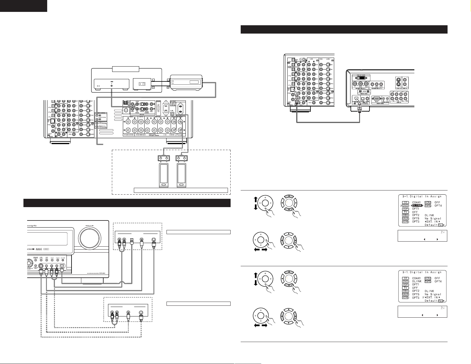
DENON LINK connections
High quality digital sound with reduced digital signal transfer loss can be enjoyed by connecting a separately sold
DENON LINK compatible DVD Player.
2
Playback using the DENON Link connector
Digital transfer and multi-channel playback of DVD audio discs and other multi-channel sources is possible by
connecting the AVR-3805 to a DENON DVD player equipped with a DENON LINK connector using the
connection cable included with the DVD player.
2
DENON LINK Setting
When a DENON DVD player and the DENON LINK have been connected, be sure to make a setting to
“DENON LINK” with the System Setup Digital In Assignment. (See page 23)
• Select the input for the playback of signals that cannot be transferred by DENON LINK.
• When the input mode is AUTO and DENON LINK has become unlocked, the unit automatically changes
over to the set connector (ANALOG or EXT. IN).
1
unit)
unit)
(Main unit)(Remote control
(Main unit)(Remote control
2
Select the digital input jack to be assigned to
the input source.
q Select input source.
w Select input jack.
q Select DLINK setting.
8
Video camera
Connecting a video camera component
• Connect the video camera component’s
output jacks to this unit’s V. AUX INPUT
jacks.
unit)
unit)
(Main unit)(Remote control
w Select input signal.
(Main unit)(Remote control
Page 9
ENGLISH
(L) (R)
(L) (R) (L) (R)
(L) (
R
)
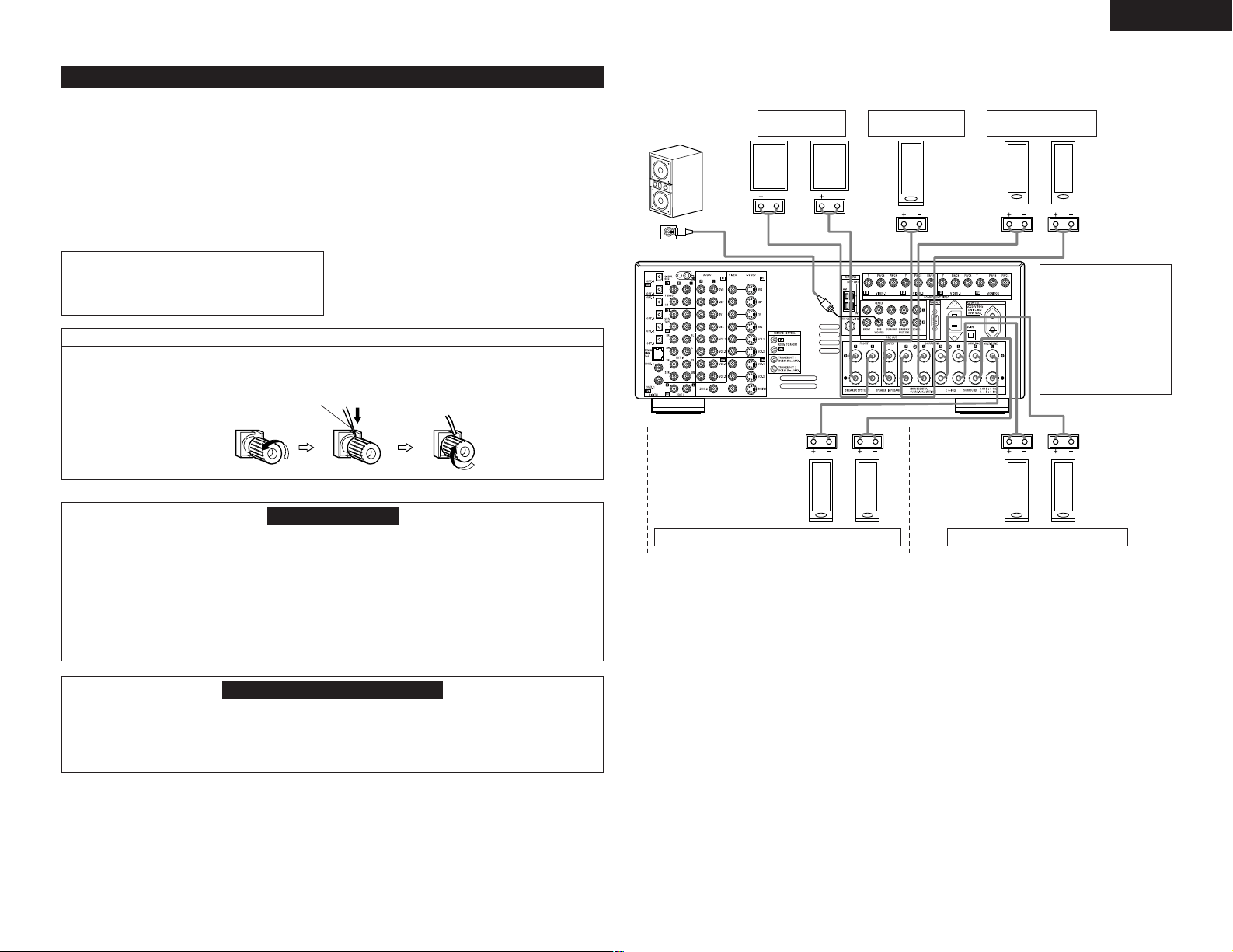
Speaker system connections
• Connect the speaker terminals with the speakers
making sure that like polarities are matched (
≈ with
≈, √ with √ ). Mismatching of polarities will result
in weak central sound, unclear orientation of the
various instruments, and the sense of direction of
the stereo being impaired.
• When making connections, take care that none of
the individual conductors of the speaker cord come
in contact with adjacent terminals, with other
speaker cord conductors, or with the rear panel.
NOTE:
NEVER touch the speaker terminals when the
power is on.
Doing so could result in electric shocks.
Connecting the speaker terminals
1. Loosen by turning
2. Insert the cord. 3. Tighten by turning
counterclockwise.
Either tightly twist or terminate the core wires.
Speaker Impedance
• Speakers with an impedance of from 6 to 16
Ω/ohms can be connected for use as front and
center speakers.
• Speakers with an impedance of 6 to 16 Ω/ohms
can be connected for use as surround speakers.
• Be careful when using two pairs of surround
speakers (A + B) at the same time, since use of
speakers with an impedance of less than 8 Ω/ohms
will lead to damage.
• The protector circuit may be activated if the set is
played for long periods of time at high volumes
when speakers with an impedance lower than the
specified impedance are connected.
clockwise.
Protector circuit
• This unit is equipped with a high-speed protection circuit. The purpose of this circuit is to protect the
speakers under circumstances such as when the output of the power amplifier is inadvertently shortcircuited and a large current flows, when the temperature surrounding the unit becomes unusually high, or
when the unit is used at high output over a long period which results in an extreme temperature rise.
When the protection circuit is activated, the speaker output is cut off and the power supply indicator LED
flashes. Should this occur, please follow these steps: be sure to switch off the power of this unit, check
whether there are any faults with the wiring of the speaker cables or input cables, and wait for the unit to
cool down if it is very hot. Improve the ventilation condition around the unit and switch the power back on.
If the protection circuit is activated again even though there are no problems with the wiring or the
ventilation around the unit, switch off the power and contact a DENON service center.
Connections
• When making connections, also refer to the operating instructions of the other components.
Connection jack for
subwoofer with built-in
amplifier (super woofer),
etc.
NOTES:
• To use Surround back with one
speaker, connect the speaker to
SURR. BACK L CH.
• The settings must be changed to use
this speaker for ZONE2/ZONE3.
See page 26.
SURROUND BACK/MULTI ZONE SPEAKER SYSTEMS
FRONT SPEAKER
SYSTEMS
CENTER SPEAKER
SYSTEM
SURROUND SPEAKER
SYSTEMS (A)
• Precautions when
connecting speakers
If a speaker is placed near
a TV or video monitor, the
colors on the screen may
be disturbed by the
speaker’s magnetism. If
this should happen, move
the speaker away to a
position where it does not
have this effect.
SURROUND SPEAKER SYSTEMS (B)
Note on speaker impedance
• The protector circuit may be activated if the set is played for long periods of time at high volumes when
speakers with an impedance lower than the specified impedance (for example speakers with an
impedance of lower than 4 Ω/ohms) are connected. If the protector circuit is activated, the speaker output
is cut off. Turn off the set’s power, wait for the set to cool down, improve the ventilation around the set,
then turn the power back on.
9
Page 10
ENGLISH
CH SEL
ENTER
e
r
y
i
œ!0
uot
q w
œ!3
œ!5
œ!4
!2
!1
œ!7
œ!6
œ!8
œ!9
@1
œ@0
@3
@2
@4@5@6@7@8
@9
#0#2
#3
#1
e
rt
y!6uio!0!1!2!3!4!5
q
w
6
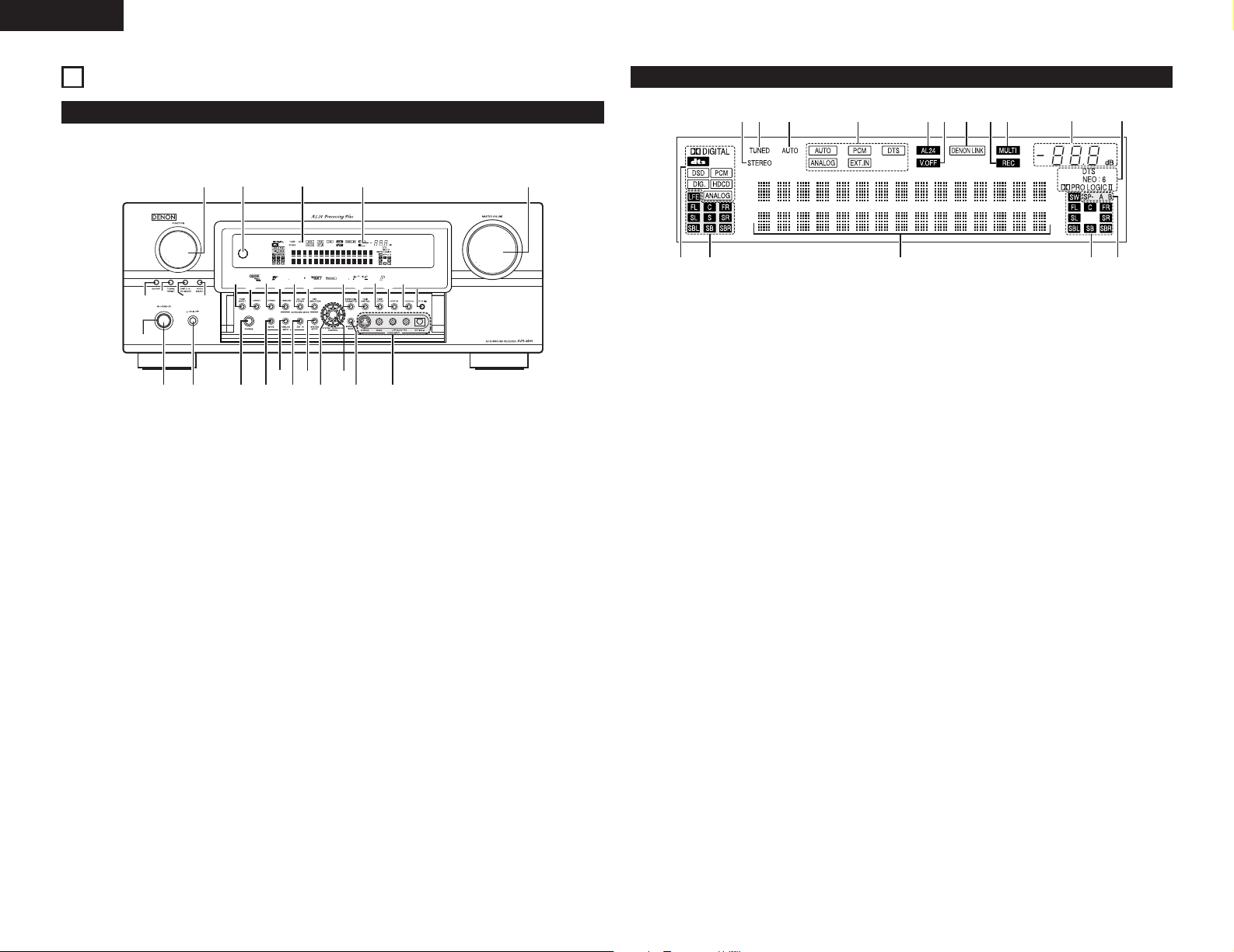
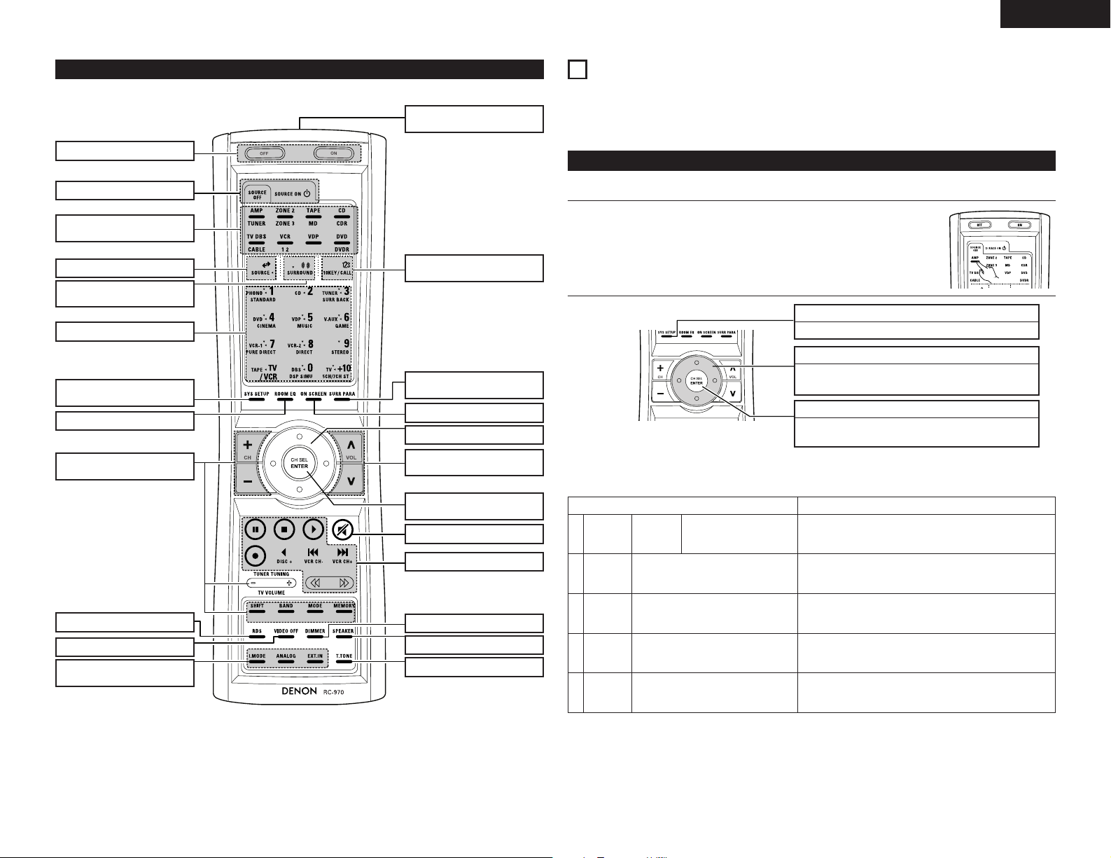
PART NAMES AND FUNCTIONS
Front Panel
• For details on the functions of these parts, refer to the pages given in parentheses ( ).
Power ON/STANDBY switch..........................(36)
q
Power switch ...........................................(36, 54)
w
Headphone jack (PHONES) ............................(38)
e
INPUT MODE button .....................................(36)
r
ANALOG button .............................................(36)
t
EXT. IN button..........................................(36, 37)
y
SYSTEM SETUP button .....................(13, 29, 46)
u
CURSOR button
i
CH SELECT/ENTER button
o
SURROUND BACK button .............................(44)
!0
V.AUX input jacks.............................................(8)
!1
PURE DIRECT button.....................................(38)
!2
DIRECT button ...............................................(38)
!3
STEREO button ..............................................(38)
!4
STANDARD button...................................(42~45)
!5
5CH/7CH STEREO button ..............................(47)
!6
DSP SIMULATION button........................(47, 48)
!7
SURROUND PARAMETER button...........(42~46)
!8
TONE CONTROL button ..........................(38, 48)
!9
TONE DEFEAT button....................................(38)
@0
STATUS button ...............................................(39)
@1
ROOM EQ button ..........................................(16)
@2
SETUP MIC jack .............................................(13)
@3
MASTER VOLUME control ............................(37)
@4
MASTER VOLUME indicator..........................(37)
@5
Display
@6
Remote control sensor
@7
(REMOTE SENSOR).......................................(30)
FUNCTION knob ....................(36, 38, 39, 41, 53)
@8
VIDEO SELECT button ...................................(38)
@9
ZONE2/3/REC SELECT button .................(39, 41)
#0
TUNING PRESET button ................................(51)
#1
SOURCE button .......................................(36, 38)
#2
POWER indicator............................................(36)
#3
Display
INPUT SIGNAL indicator
q
The respective indicator will light corresponding
to the input signal.
INPUT SIGNAL CHANNEL indicator
w
The channels included in the input source will
light.
Information display
e
This displays the surround mode, function name
or setting value, etc.
OUTPUT SIGNAL CHANNEL indicator
r
The audio channels output from this unit will
light.
SPEAKER indicator
t
This lights corresponding to the settings of the
surround speakers of the various surround
modes.
MASTER VOLUME indicator
y
This displays the volume level.
The Setup item number is displayed in System
Setup.
MULTI(ZONE) indicator
u
ZONE2 mode is selected in ZONE2/REC SELECT.
REC OUT SOURCE indicator.
i
REC OUT mode is selected in ZONE2/REC
SELECT.
DENON LINK indicator
o
This lights during playback in a DENON LINK
connection.
V.OFF indicator
!0
This lights when the operation of the video circuit
has been turned off.
AL24 indicator
!1
The AL24 indicator lights when the PURE
DIRECT, DIRECT, STEREO, MULTI PURE
DIRECT, MULTI CH DIRECT, MULTI CH IN mode
is selected in the PCM input signal.
INPUT MODE indicator
!2
This lights corresponding to the setting of the
INPUT mode.
AUTO indicator
!3
This lights when the broadcast station is selected
in the AUTO tuning mode.
TUNED indicator
!4
This lights when an FM/AM broadcast has been
received.
STEREO indicator
!5
This lights when an FM stereo broadcast has
been received.
Decoder indicator
!6
This lights when each decoder is operating.
10
Page 11
ENGLISH
Remote control unit
• For details on the functions of these parts, refer to the pages given in parentheses ( ).
Remote control signal
transmitter ................................(30)
Power buttons....................(31~36)
SYSTEM buttons ................(32, 41)
Mode selector
buttons ...................(11, 30, 32, 36)
Input source button............(30, 36)
Surround mode
button.....................(30, 36, 38, 42)
SYSTEM buttons................(30~32)
SYSTEM SETUP
button .................................(11, 29)
ROOM EQ button.....................(16)
Tuner system
buttons ....................(31,34, 41, 50)
10KEY/SYSTEM CALL
button.................................(30~35)
SURROUND PARAMETER button
...............................(42~45, 47, 48)
ON SCREEN button............(39, 45)
Cursor buttons..........................(11)
Master volume control
buttons ...............................(37, 41)
CH SELECT/
ENTER button...............(11, 41, 42)
MUTING button........................(38)
SYSTEM buttons................(30~32)
7
SETTING UP THE SYSTEM
• Once all connections with other AV components have been completed as described in “CONNECTIONS”
(see pages 5 to 9), make the various settings described below on the monitor screen using the AVR-3805’s
on-screen display function.
These settings are required to set up the listening room’s AV system centered around the AVR-3805.
Use the following buttons to set up the system
• Use the following buttons to set up the system.
Check that the remote control unit set to AMP mode.
1
2
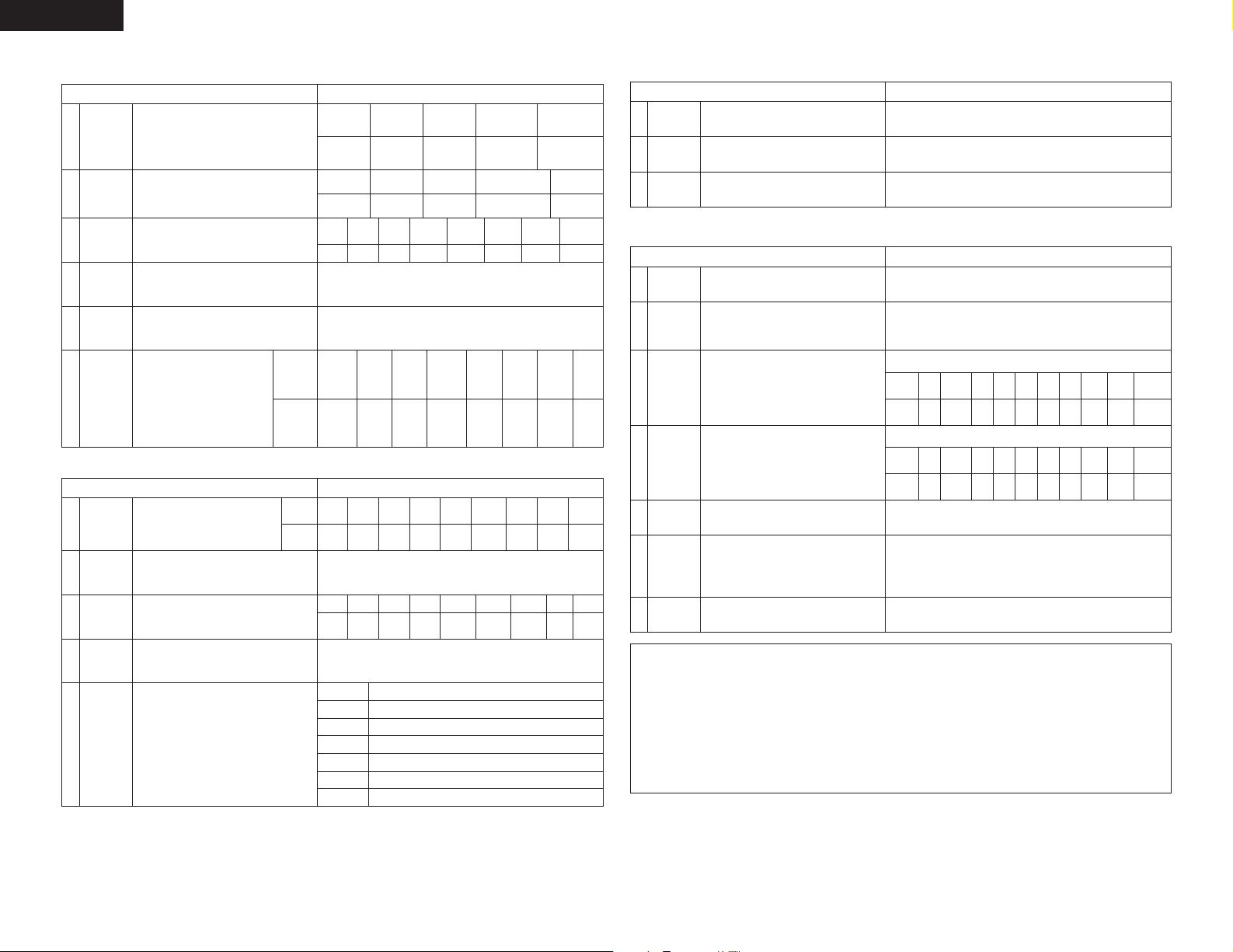
• System setup items and default values (set upon shipment from the factory)
1. Auto Setup/Room EQ
Auto Setup/Room EQ Default settings
1
2
Auto Setup
Manual EQ
Setup
Power Amp
Assignment
This parameter is for optimizing the Room EQ with
which the audio signals are produced from the
speakers.
Set this to switch the surround
back channel’s power amplifier
for use for zone2 or zone3.
SYSTEM SETUP button
Press this to display the system setup menu.
CURSOR buttons
Use these to move the cursors the left, right, up and
down on the screen
ENTER button
Press this to switch the display.
Also use this button to complete the setting.
SURROUND BACK
All Channel and Frequency=0 dB
RDS button.........................(52~54)
VIDEO ON/OFF button .............(38)
INPUT MODE selector
buttons .....................................(36)
DIMMER button .......................(39)
SPEAKER button ......................(39)
TEST TONE button ...................(41)
Room EQ
3
Setup
Direct Mode
4
Setup
Mic Input
5
Select
Set the Room EQ setting with All or Assign for
each surround mode.
Set the ON/OFF setting of Room EQ, in the case of
the surround mode is in Direct or Pure Direct.
Set this to switch the Mic Input jack for use for Mic
or V.Aux L-channel input jack.
All
OFF
Mic
11
Page 12
ENGLISH
2. Speaker Setup
Input the combination of speakers in your
Speaker
1
Configuration
Delay Time
2
Channel
3
Level
Crossover
4
Frequency
Subwoofer
5
mode
(Surround
Speaker
6
Setting)
system and their corresponding sizes (SMALL for
regular speakers, LARGE for full-size, full-range) to
automatically set the composition of the signals
output from the speakers and the frequency
response.
This parameter is for optimizing the timing with
which the audio signals are produced from the
speakers and subwoofer according to the listening
position.
This adjusts the volume of the signals output from
the speakers and subwoofer for the different
channels in order to obtain optimum effects.
Set the frequency (Hz) below which the bass so of
the various speaker is to be output from the
subwoofer.
This selects the subwoofer speaker for playing
deep bass signals.
Use this function when using multiple
surround speaker combinations for
more ideal surround sound. Once the
combinations of surround speakers to
be used for the different surround
modes are preset, the surround
speakers are selected automatically
according to the surround mode.
3. Input Setup
1
2
3
4
5
Digital In
Assignment
Ext. In
Subwoofer
Level
Component
In Assign
Video Input
Mode
Auto Tuner
Presets
This assigns the digital input jacks for the
different input sources.
Set the Ext. In Subwoofer terminal playback
level.
This assigns the color difference (component)
video input jacks for the different input sources.
Set the input signal to be output from the monitor
output terminal.
FM stations are received automatically and stored
in the memory.
Speaker Setup Default settings
Front Sp.
Front L & R Center Surround L & RSubwoofer
3.6 m (12 ft) 3.6 m (12 ft) 3.0 m (10 ft)3.6 m (12 ft)
Front L
0 dB 0 dB 0 dB 0 dB 0 dB 0 dB
Surround
Surround
Input Setup Default settings
DOLBY/
mode
speaker
DTS
CINEMA
Input
CD DVD VDP TV DBS
source
Digital
COAX1 COAX2 OPT1 OFF OPT2 OPT4
Inputs
DVD
VIDEO
1
A1 ~ A8
B1 ~ B8
C1 ~ C8
D1 ~ D8 90.1 MHz
E1 ~ E8 90.1 MHz
F1 ~ F8 90.1 MHz
G1 ~ G8 90.1 MHz
Center Sp.
Large
Front R Center
DOLBY/
DTS
MUSIC
AAA A AA
VDP TV VCR-1 V. AUX
NONE
87.5/89.1/98.1/108.0/90.1/90.1/90.1/90.1 MHz
522/603/999/1404/1611 kHz, 90.1/90.1/90.1 MHz
90.1 MHz
Subwoofer
Small SmallYes
Surround
L
0 dB
DOLBY/
PL IIx
SCREEN
GAME
Subwoofer = +15 dB
DBS
VIDEO
VIDEO
2
3
Surround
R
80Hz
LFE
WIDE
5CH/7CH
STEREO
A
NONE NONE
AUTO
Surround Sp.
A / B
Surround
Back L
0 dB
V. AUX
OPT5
VCR-2
NONE
Surround
Back R
DSP
SIMULATION
A
VCR-1
OPT3
Surround Back
Sp.
Small / 2spkrs
SBL & SBR
3.0 m (10 ft)
Subwoofer
MULTI
CH
MODE
CDR/
VCR-2
TAPE
OFF
——
——
EXT.IN
4. Advanced Playback
Advanced Playback Default settings
1
2
3
Audio Delay
Dolby Digital
Setup
Auto
Surround
Mode
Set the audio delay to delay time the sound and
synchronize it with the picture.
Turn the audio compression on or off when downmixing Dolby Digital signals.
Set the Auto surround mode function.
0 ms
OFF
Auto Surround Mode = ON
5. Option Setup
Option Setup Default settings
1
2
3
4
5
6
7
Power AMP
Assignment
Zone2 vol.
Level
Trigger Out1
Setup
Trigger Out2
Setup
Muting Level
On Screen
Display
Setup Lock
Set this to switch the surround back channel’s
power amplifier for use for zone2 or zone3.
This sets the output level the zone2 output jacks.
This menu is not displayed, when “ZONE2” is
selected at Option Setup “Power Amp Assign”.
Set the Trigger Out1 output for the each input
sources.
Set the Trigger Out2 output for the each input
sources.
This sets the amount of attenuation at audio
output muting.
This sets whether or not to display the on-screen
display that appears on the monitor screen when
the controls on the remote control unit or main unit
are operated.
A setting to prevent flickering.
Set whether or not to lock the system setup
settings so that they cannot be changed.
CDCDTUNER
PHONO
OFFONOFFONOFF
PHONO
Surround Back
Variable
ZONE=MAIN
CDR/
DVD
VDP
TAPE
ON
ON
OFF
ZONE=2
CDR/
TUNER
DVD
VDP
TAPE
ON
ON
ON
ON
---dB (minimum)
On Screen Display = ON / Mode 1
Setup Lock = OFF
TV
ON
TV
ON
DBS
VCR-1
ONONON
DBS
VCR-1
VCR-2
ON
VCR-2
ON
ON
NOTES:
• The on-screen display signals are output with priority to the S-VIDEO MONITOR OUT jack during playback
of a video component. For example, if the TV monitor is connected to both the AVR-3805’s S-Video and
video monitor output jacks and signals are input to the AVR-3805 from a video source (VDP, etc.) connected
to both the S-Video and video input jacks, the on-screen display signals are output with priority to the SVideo monitor output. If you wish to output the signals to the video monitor output jack, do not connect a
cord to the S-VIDEO MONITOR OUT jack. (For details, see page 29.)
• The AVR-3805’s on-screen display function is designed for use with high resolution monitor TVs, so it may
be difficult to read small characters on TVs with small screens or low resolutions.
• The setup menu is not displayed when headphone are being used.
V. AUX
ON
V. AUX
ON
12
Page 13
ENGLISH
AA
BB
AA
BB
SB SB SB SB
Auto Set/RoomEQ
*System Setup
Listening position
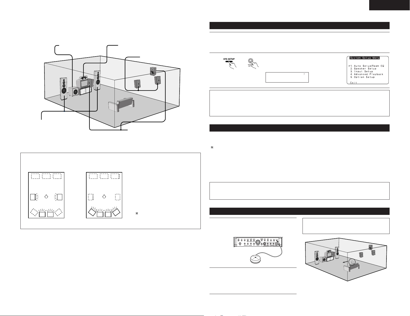
• Speaker system layout
Basic system layout
• The following is an example of the basic layout for a system consisting of eight speaker systems and a
television monitor:
Subwoofer Center speaker system
Surround back speaker systems
Front speaker systems
Set these at the sides of the TV or
screen with their front surfaces as flush
with the front of the screen as possible.
With the AVR-3805 it is also possible to use the surround speaker selector function to choose the best layout for
a variety of sources and surround modes.
• Surround speaker selector function
This function makes it possible to achieve the optimum sound fields for different sources by switching
between two systems of surround speakers (A and B).
Surround speaker systems
Before setting up the system
Check that all the connections are correct, then turn on the main unit’s power.
1
Setup will not be possible when the unit is set to Pure Direct ON, the Video Off mode, or when the
headphones are plugged in. Therefore, please cancel the mode or reverse the condition.
2
unit)
NOTES:
• The System Setup menu composition is of a layered design that includes the related items below the large
table title as contained in the tables of Pages 11 and 12.
• Wherever your position in System Setup, one more press of the System Setup button permits a move to
one level higher.
(Main unit)(Remote control
Display the System Setup Menu.
Auto setup/Room EQ
The Auto Setup function of this unit performs an analysis of the speaker system and measures the acoustic
characteristics of your room to permit an appropriate automatic setting.
When performing Auto Setup, a microphone is required for the setup.
2
Measurement and setting details
q : This sets the speaker connection mode, polarity, and bass reproduction ability.
w : This sets the optimum delay time from each speaker corresponding to the listening position.
e : This sets the volume that is output from each speaker.
r : This sets the frequency response of each speaker.
NOTE:
• A loud test tone is output during the measurement. Please consider this should you be planning nighttime
measurements, and consider not allowing small children into the listening room at this time.
Using A only Using B only
SB: SURROUND BACK SPEAKER
Connecting the microphone for Auto Setup
Connect the optional microphone for Auto
1
Setup to the Setup Mic connector on the front
panel of the unit.
CH SEL
ENTER
Place the microphone for Auto Setup at the
2
actual listening position which will be at the
same height as your ears. Use a tripod or level
surface at positioning.
NOTE:
• When using other microphone. (See page 17)
13
Page 14
ENGLISH
CH SEL
ENTER
CH SEL
ENTER
CH SEL
ENTER
CH SEL
ENTER
Auto Set/RoomEQ
*System Setup
CH SEL
ENTER
CH SEL
ENTER
CH SEL
ENTER
CH SEL
ENTER
Auto Setup
*AutoSet/RoomEQ
CH SEL
ENTER
CH SEL
ENTER
P.Amp: SB
*Auto Setup
CH SEL
ENTER
CH SEL
ENTER
CH SEL
ENTER
CH SEL
ENTER
Start
*Auto Setup
CH SEL
ENTER
CH SEL
ENTER
FL
FR CSW
1
2
SLA
SRA SLB SRB SBL
SBR
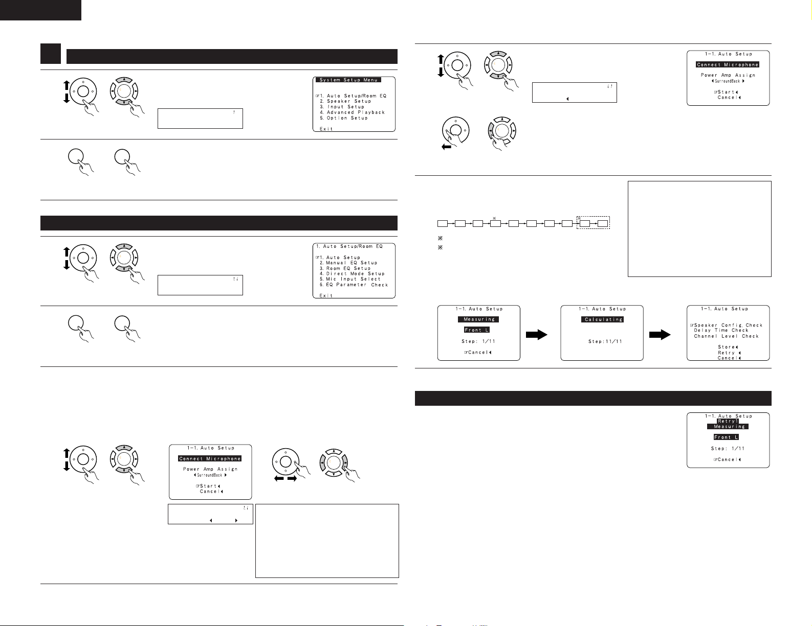
Setting the Auto Setup / Room EQ
1
1
(Remote control
unit)
(Main unit)
2
(Remote control
unit)
1-1 Setting the Auto Setup
(Main unit)
1
(Remote control
unit)
(Main unit)
2
(Remote control
unit)
(Main unit)
Select “Auto Setup / Room EQ” at the
System Setup Menu.
Display the Auto Setup / Room EQ menu.
Select “Auto Setup” at the Auto Setup /
Room EQ Menu.
Display the Auto Setup screen.
4
unit)
(Main unit)(Remote control
q Select the “Start”.
w Press the CURSOR left button.
unit)
Start the measurements.
5
Measurement of each channel is performed as follows.
(Main unit)(Remote control
Display
Subwoofer speaker is measured twice.
When “ZONE2” or ”ZONE3” is selected, this is not
displayed.
After each channel is measured, “Calculating”
appears.
The display switches to Auto Setup check screen
automatically.
NOTES:
• Measurement is canceled when
MASTER VOLUME is operated while
the Auto Setup is performed.
• Set the volume to halfway and set the
crossover frequency to the maximum
or low pass filter off if your subwoofer
speaker can adjust the output volume
and the crossover frequency.
3
14
Check the “Power Amp Assign” setting.
• When “Surround Back” is selected, the test tone during Auto Setup will be output from the
Surround Back speaker.
• When “ZONE2” or “ZONE3” is selected, change the setting to ”ZONE2” or “ZONE3”. The test
tone during Auto Setup is set so that it will not be output to ZONE2 or ZONE3 (Another room).
q Select the Power Amp Assign setting.
w Select “Surround Back”, “ZONE2” or
“ZONE3”.
unit)
(Main unit)(Remote control
unit)
(Main unit)(Remote control
NOTE:
• When “ZONE2” or “ZONE3” is
selected at System Setup Menu
“Power Amp Assign”, surround back
speaker is not displayed as the target of
setup in “2-1. Speaker Config.”. The
results is reflected in “5-1. Power Amp
Assign”.
About automatic retry
Remeasurement starts automatically to receive proper result of measurement.
Remeasurement is performed to 2 times, and “Retry1” or “Retry2” is displayed
on screen during remeasurement.
Page 15
ENGLISH
CH SEL
ENTER
CH SEL
ENTER
Sp Config.Check
*Auto Setup
CH SEL
ENTER
CH SEL
ENTER
CH SEL
ENTER
CH SEL
ENTER
CH SEL
ENTER
CH SEL
ENTER
Store
*Auto Setup
CH SEL
ENTER
CH SEL
ENTER
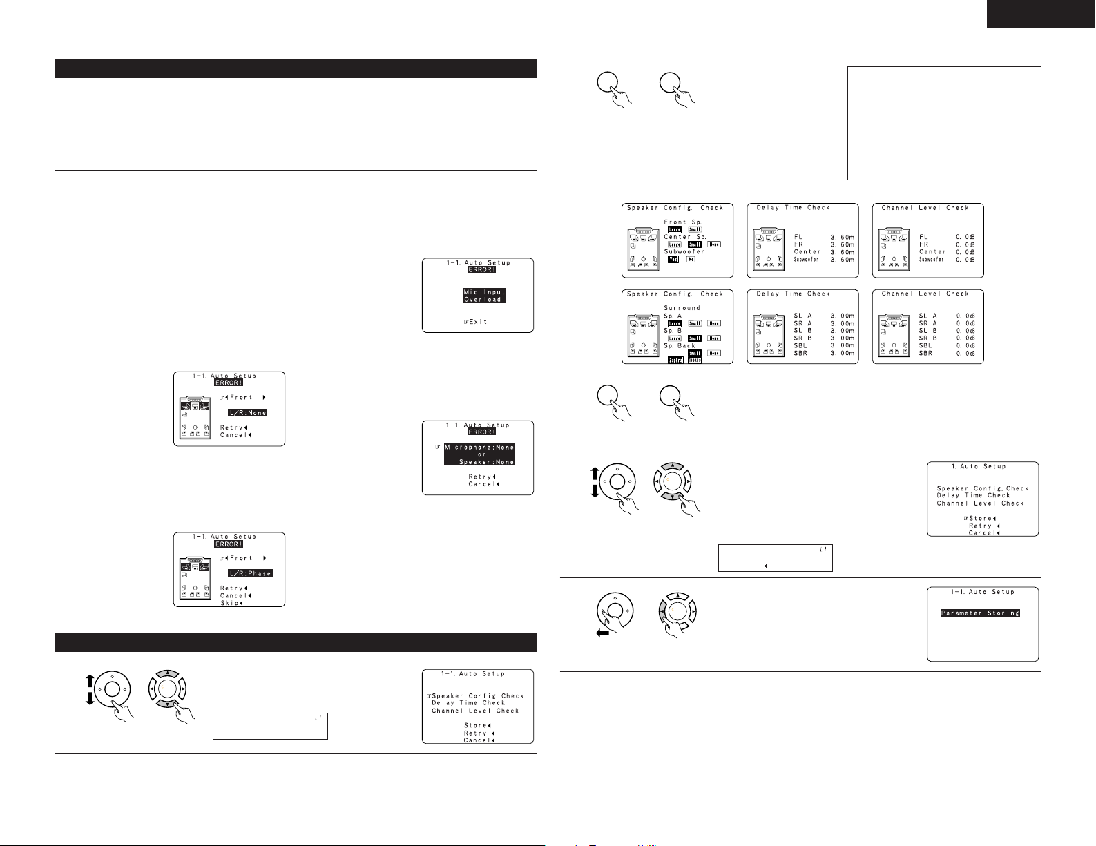
About the error message
These error screens will be displayed when performing the measurements of Auto Setup / Room EQ and the
automatic measurements can not be completed because of the speaker arrangement, measurement
environment, or other factors. Please check the following matters, reset the pertinent items, and measure again.
When there is too much noise in the room, the speakers may not be detected properly. Should this happen,
perform the measurements when the noise level is low, or switch off the power of the equipment that is
producing the noise for the duration of the measurements.
q This screen will be displayed when the speakers
required for producing suitable reproduction have
not been detected.
• The front L and front R speakers were not
properly detected.
• Only one channel of the surround (A) and
surround (B) speakers was detected.
• Sound was output from the R channel when
only one surround back speaker was connected.
• The surround back or the surround (B) speaker
was detected, but the surround (A) speaker was
not detected.
Check that the pertinent speakers are properly
connected.
(see page 9)
w This screen will be displayed when the speaker
polarity is connected in reverse.
Check the polarity of the pertinent speakers.
For some speakers, the screen below may be
displayed even though the speakers are
properly connected. If so, select “Skip
0
”.
e This screen will be displayed when accurate
measurements cannot be made due to the input
level to the microphone being too high.
Set up the speakers so that their position is
farther away from the listening position.
Lower the volume of the subwoofer speaker.
r This screen will be displayed when the
measurement microphone is not connected, or
when all of the speakers have not been detected.
Connect the measurement microphone to the
microphone connector.
Check the speaker connections.
2
Press the ENTER button
and display the verification
screen.
unit)
(Main unit)(Remote control
NOTE:
• When measurements have been
made using the measurement
microphone, speakers with a built-in
filter such as subwoofers might be set
with a value that differs from the
physical distance because of the
internal electrical delay.
[Speaker Config. Check] [Delay Time Check] [Channel Level Check]
3
unit)
(Main unit)(Remote control
4
If the check ends, press the ENTER button again.
Select from the following three items based
on the measurement results.
• Set with the checked measurement
value.
• Perform the measurement again.
unit)
(Main unit)(Remote control
• Cancel the checked measurement
value.
Check of the measurement results
1
unit)
5
When the “Store” is selected, all parameters
are stored up.
When the “Retry” is selected, it measures
again.
unit)
(Main unit)(Remote control
Select the items.
The measurement results of each item can be
checked here.
(Main unit)(Remote control
15
Page 16
ENGLISH
CH SEL
ENTER
CH SEL
ENTER
Manual EQ Setup
*AutoSet/RoomEQ
CH SEL
ENTER
CH SEL
ENTER
Channel : FL
*ManualEQ Setup
CH SEL
ENTER
CH SEL
ENTER
SB
FL
FR C
SLA
SLBSRB
SBL
SBR
1spkr
SRA
Channel : FL
*ManualEQ Setup
CH SEL
ENTER
CH SEL
ENTER
63Hz : 0.0dB
*ManualEQ Setup
CH SEL
ENTER
CH SEL
ENTER
CH SEL
ENTER
CH SEL
ENTER
CH SEL
ENTER
CH SEL
ENTER
Room EQ Setup
*AutoSet/RoomEQ
CH SEL
ENTER
CH SEL
ENTER
SurMode:ALL
*Room EQ Setup
CH SEL
ENTER
CH SEL
ENTER
CH SEL
ENTER
CH SEL
ENTER
OFF Normal
Manual Flat
Front
RoomEQ Normal
*Room EQ Setup
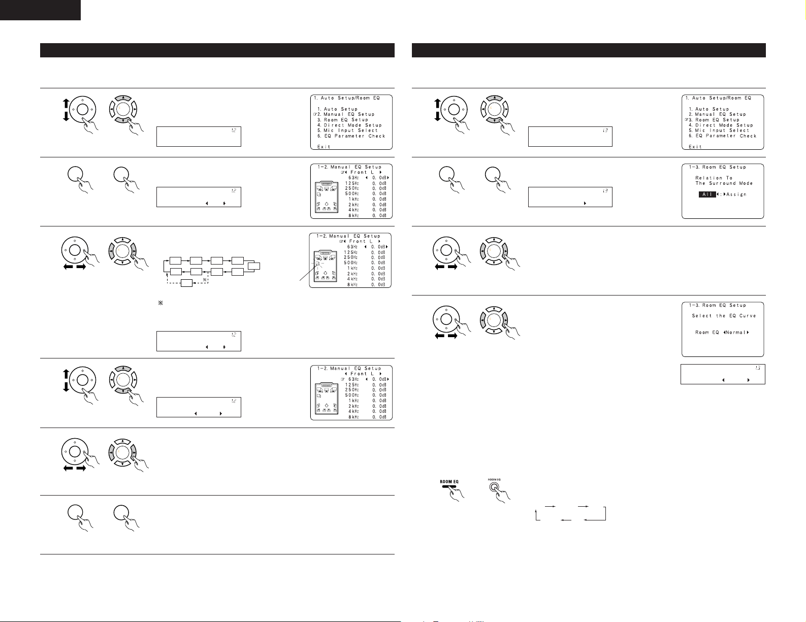
1-2 Setting the Manual EQ Setup
Adjust the tone of the various speakers except subwoofer speaker while listening to the sound (music).
1
unit)
(Main unit)(Remote control
2
unit)
(Main unit)(Remote control
3
unit)
(Main unit)(Remote control
4
unit)
(Main unit)(Remote control
5
unit)
(Main unit)(Remote control
Select “Manual EQ Setup” at the Auto Setup
/ Room EQ Menu.
Display the Manual EQ Setup screen.
Select the speaker to be set.
The display changes as follows.
Flashing
When the surround back speaker setting
is set to “1spkr” at “Speaker
Configuration”, this is set to “SB”.
Select the frequency.
Use the cursor left and right buttons to adjust the Gain level.
• Each frequency can be adjusted the range from –6 dB to +6 dB in 0.5 dB
step.
1-3 Setting the Room EQ Setup
Select the setting of an Equalizer that has been set with Auto Setup or Manual EQ.
1
unit)
(Main unit)(Remote control
2
unit)
(Main unit)(Remote control
3
unit)
(Main unit)(Remote control
4
unit)
(Main unit)(Remote control
Select “Room EQ Setup” at the Auto Setup /
Room EQ Menu.
Display the Room EQ Setup screen.
Select All or Assign.
• All : The Equalizer to all Surround mode is set as once.
• Assign : The Equalizer to each surround mode is to set individually.
When the All is selected and press the ENTER
button, display the Select the EQ Curve
screen.
Select the Equalizer setting.
• OFF : The Equalizer is not used.
• Normal : Adjusts the frequency
response of all speakers
suitable for general surround
system.
• Flat : Adjusts the frequency
response of all speakers flat.
This is suitable for music
reproduction like ITU-R
speaker setting.
• Front : Adjusts the characteristics of each speaker to the
characteristics of the front speakers.
• Manual : Selects the setting value that was set in the Manual EQ
setup.
Whenever the Room EQ button on Main unit or Remote control unit is
pressed, the display switches as shown below.
6
16
unit)
Enter the setting.
The Auto Setup / Room EQ Menu reappears.
unit)
(Main unit)(Remote control
(Main unit)(Remote control
Page 17
ENGLISH
CH SEL
ENTER
CH SEL
ENTER
Direct Mode
*AutoSet/RoomEQ
CH SEL
ENTER
CH SEL
ENTER
Room EQ : OFF
*Direct Mode
CH SEL
ENTER
CH SEL
ENTER
CH SEL
ENTER
CH SEL
ENTER
CH SEL
ENTER
CH SEL
ENTER
Mic In Select
*AutoSet/RoomEQ
CH SEL
ENTER
CH SEL
ENTER
CH SEL
ENTER
CH SEL
ENTER
CH SEL
ENTER
CH SEL
ENTER
Mic
*Mic In Select
CH SEL
ENTER
CH SEL
ENTER
CH SEL
ENTER
CH SEL
ENTER
NOTES:
• The Equalizer setting of Normal, Flat and Front can be selected after
performing the Auto Setup.
• When the speaker set as “None” with the Auto Setup is change to on
manually, the equalizer of “Normal”, “Front” and “Flat” cannot be
used.
• The Equalizer setting can be selected directly by ROOM EQ button in
Main unit or Remote control unit.
• When headphone is connected, the Room EQ cannot be used.
5
Enter the setting.
The Auto Setup / Room EQ Menu reappears.
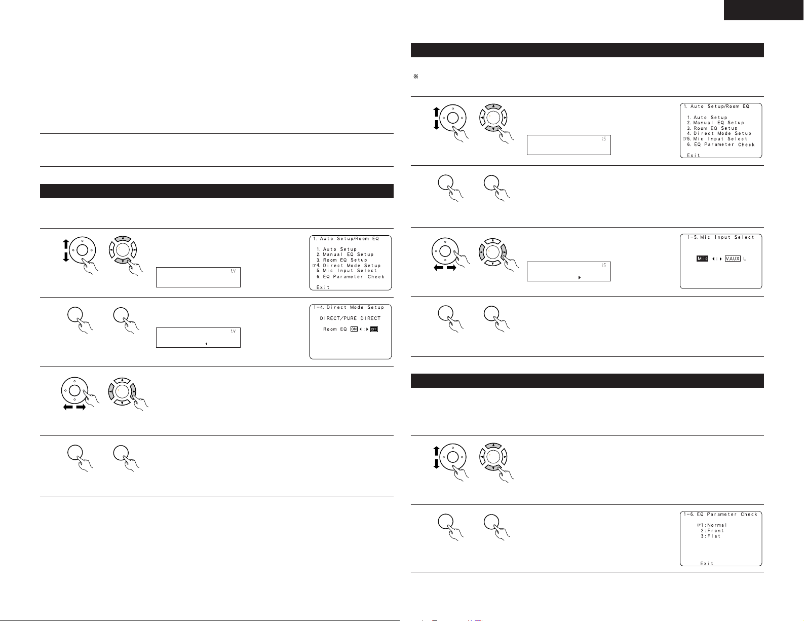
1-4 Setting the Direct Mode
Perform the ON/OFF setting of Room EQ when the surround mode is Direct or Pure Direct.
1
unit)
(Main unit)(Remote control
2
unit)
(Main unit)(Remote control
Select “Direct Mode Setup” at the Auto
Setup / Room EQ Menu.
Display the Direct Mode Setup screen.
1-5 Setting the MIC Input Select
Sets whether the setup microphone is connected to the PIN JACK connector or the MINI JACK connector.
Please ask the DENON Authorized Service Center about the usable microphone other than the option setup.
1
unit)
(Main unit)(Remote control
2
unit)
(Main unit)(Remote control
3
unit)
(Main unit)(Remote control
4
unit)
(Main unit)(Remote control
Select “Mic Input Select” at the Auto Setup /
Room EQ Menu.
Display the Mic Input Select screen.
Select the Mic input jack or V.AUX L jack.
Enter The setting.
The Auto Setup / Room EQ Menu reappears.
3
4
unit)
unit)
Select ON or OFF.
1-6 Check the EQ parameter
• The frequency characteristic of each speaker is rectified and the tone of the speaker is unified.
The EQ parameters that were set in Auto Setup can be checked.
(Main unit)(Remote control
Enter the setting.
The Auto Setup / Room EQ Menu reappears.
(Main unit)(Remote control
This item is automatically displayed, after the measurement result of the “Auto Setup / Room EQ” is decided.
1
unit)
(Main unit)(Remote control
2
unit)
(Main unit)(Remote control
Select “EQ Parameter Check” at the Auto Setup / Room EQ Menu.
Display the EQ Parameter Check screen.
17
Page 18
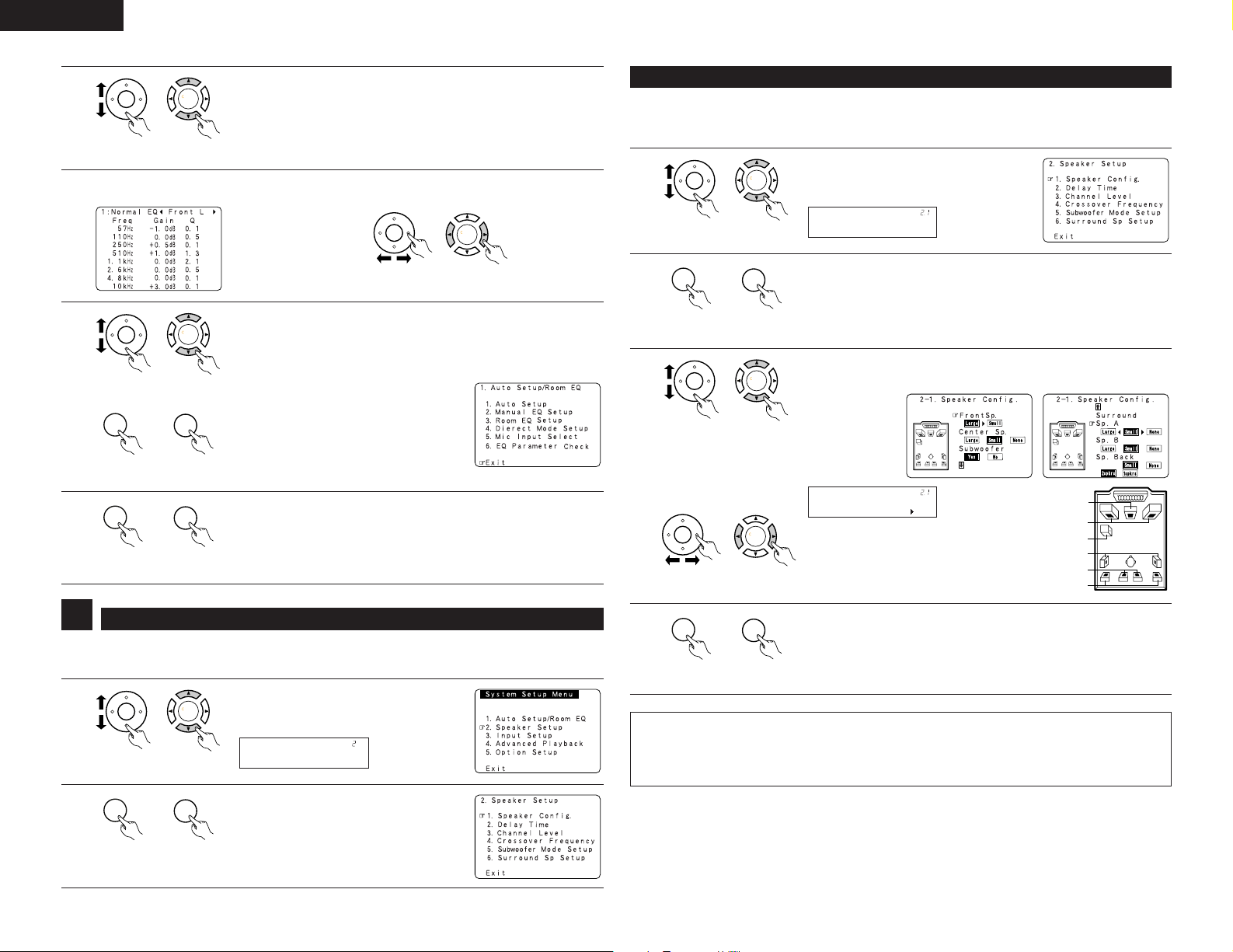
ENGLISH
CH SEL
ENTER
CH SEL
ENTER
CH SEL
ENTER
CH SEL
ENTER
CH SEL
ENTER
CH SEL
ENTER
CH SEL
ENTER
CH SEL
ENTER
CH SEL
ENTER
CH SEL
ENTER
CH SEL
ENTER
CH SEL
ENTER
CH SEL
ENTER
CH SEL
ENTER
Speaker Setup
*System Setup
CH SEL
ENTER
CH SEL
ENTER
Speaker Config.
*Speaker Setup
CH SEL
ENTER
CH SEL
ENTER
CH SEL
ENTER
CH SEL
ENTER
FrontSp: Large
*Speaker Config
CH SEL
ENTER
CH SEL
ENTER
CH SEL
ENTER
CH SEL
ENTER
3
unit)
Dislay the parameter screen.
4
6
unit)
unit)
7
unit)
Select the Equalizer curve.
2-1 Setting the type of speakers
• The composition of the signals output to each channels and the frequency response are adjusted
automatically according to the combination of speakers actually being used.
(Main unit)(Remote control
Select the speaker channel.
5
unit)
(Main unit)(Remote control
If the check ends, select “Exit” and press the ENTER button. The Auto
Setup Menu / Room EQ reappears.
(Main unit)(Remote control
(Main unit)(Remote control
1
unit)
(Main unit)(Remote control
2
unit)
(Main unit)(Remote control
3
unit)
(Main unit)(Remote control
Enter the Setting.
Select “Exit” and press the ENTER button at the Auto Setup / Room EQ
Menu screen.
(Main unit)(Remote control
The System Setup Menu reappears.
unit)
(Main unit)(Remote control
Select “Speaker Config.” at the Speaker
Setup Menu.
Display the speaker configuration screen as below.
Set whether speakers are connected or not and, if so, their size parameters.
q Select the speaker
Center Sp.
w Select the parameter
Front Sp.
Subwoofer
Surround Sp. A
Surround back Sp.
Surround Sp. B
2
• Cross over Frequency and Subwoofer Mode Setup is not displayed when not using a subwoofer.
• Surround Sp setup is displayed when using both surround speakers A and B.
1
2
18
Setting the Speaker Setup
Select “Speaker Setup” at the System Setup
Menu.
(Remote control
unit)
(Remote control
unit)
(Main unit)
Display the Speaker Setup Menu screen.
(Main unit)
4
unit)
(Main unit)(Remote control
ENTER the setting.
The Speaker Setup Menu reappears.
NOTE:
• Select “Large” or “Small” not according to the actual size of the speaker but according to the speaker’s
capacity for playing low frequency (bass sound below the frequency set for the Crossover Frequency)
signals. If you do not know, try comparing the sound at both settings (setting the volume to a level low
enough so as not to damage the speakers) to determine the proper setting.
Page 19
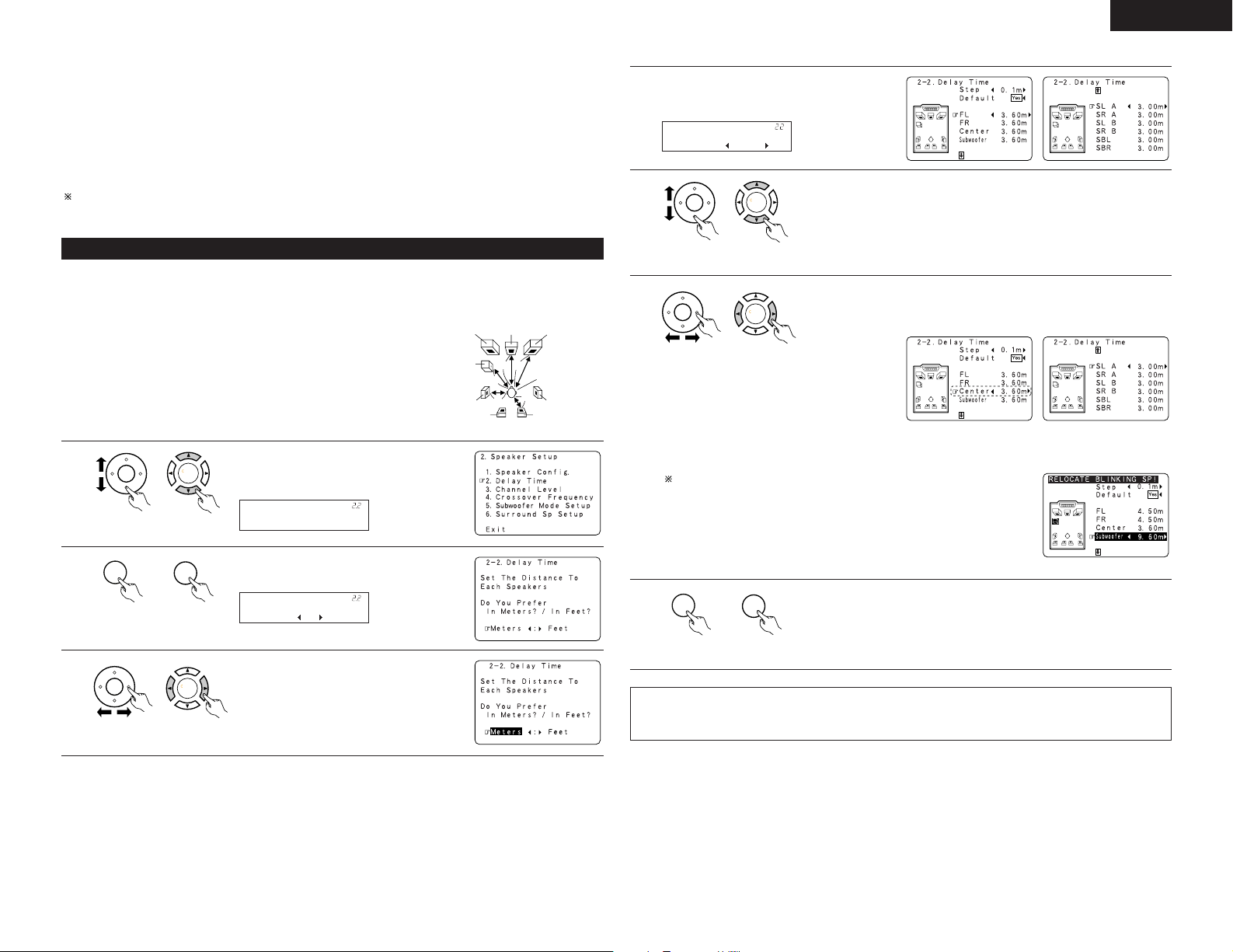
ENGLISH
L1
L2
L5
L3
L4
CH SEL
ENTER
CH SEL
ENTER
Delay Time
*Speaker Setup
CH SEL
ENTER
CH SEL
ENTER
Meters : Feet
*Delay Time
CH SEL
ENTER
CH SEL
ENTER
FL : 12.0ft
*Delay Time
CH SEL
ENTER
CH SEL
ENTER
CH SEL
ENTER
CH SEL
ENTER
CH SEL
ENTER
CH SEL
ENTER
• Parameters
Large.................Select this when using speakers that have sufficient performance for reproducing bass
sound below the frequency set for the Crossover Frequency mode.
Small.................Select this when using speakers that do not have sufficient performance for reproducing
bass sound below the frequency set for the Crossover Frequency mode. When this is set,
bass sound with a frequency below the frequency set for the Crossover Frequency mode is
sent to the subwoofer.
None……..........Select this when no speakers are installed.
Yes/No… ...........Select “Ye s ” when a subwoofer is installed, “No” when a subwoofer is not installed.
2spkrs/1spkr .....Set the number of speakers to be used for the surround back channel.
If the subwoofer has sufficient low frequency playback capacity, good sound can be achieved even when
“Small” is set for the front, center and surround speakers.
2-2 Setting the Delay Time
• Input the distance between the listening position and each speakers to set the delay time for the surround
playback.
• The delay time can be set separately for surround speakers A and B.
Preparations:
Measure the distances between the listening position and the speakers
(L1 to L5 on the diagram at the right).
L1: Distance between center speaker and listening position
L2: Distance between front speakers and listening position
L3: Distance between surround speakers and listening position
L4: Distance between surround back speakers and listening position
L5: Distance between subwoofer and listening position
1
unit)
(Main unit)(Remote control
2
unit)
(Main unit)(Remote control
3
unit)
(Main unit)(Remote control
Select “Delay Time” at the Speaker Setup
Menu.
Display the Delay Time screen.
Select the desired unit, meters or feet.
Subwoofer
Center FRFL
Listening position
SL
SR
SBRSBL
Once “Meters” or “Feet” is selected in step 3,
4
the Delay Time screen appears automatically.
5
unit)
(Main unit)(Remote control
6
Select the speaker to be set.
The picture of the speaker selected blinks.
Set the distance between the center speaker and listening position.
The distance changes in units of 0.03 meters (0.1 foot) each time the button
is pressed. Select the value closest to the measured distance.
unit)
(Main unit)(Remote control
Example: When the distance is
set to 3.6 m for the
center speaker
If “Ye s ” is selected for “Default”, the settings are automatically reset
to the default values.
Please note that the difference of distance for every speaker should be 6.0
m (20 ft) or less. If you set an invalid distance, a CAUTION notice, such as
screen right will appear. In this case, please relocate the blinking speaker(s)
so that its distance is no larger than the value shown in highlighted line.
7
Enter the setting.
The Speaker Setup Menu reappears.
The AVR-3805 automatically sets the optimum surround delay time for the
listening room.
unit)
(Main unit)(Remote control
NOTE:
• If the distance unit is changed after the delay time is set, the settings are reset to the factory default values
(see page 12).
19
Page 20
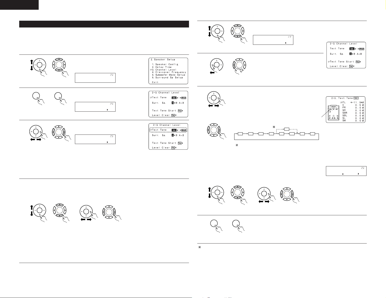
ENGLISH
CH SEL
ENTER
CH SEL
ENTER
Channel Level
*Speaker Setup
CH SEL
ENTER
CH SEL
ENTER
T.Tone: Auto
*Channel Level
CH SEL
ENTER
CH SEL
ENTER
T.Tone: Auto
*Channel Level
CH SEL
ENTER
CH SEL
ENTER
CH SEL
ENTER
CH SEL
ENTER
CH SEL
ENTER
CH SEL
ENTER
Tone Start:Yes
*Channel Level
CH SEL
ENTER
CH SEL
ENTER
FL C FR SR SBR SBL SL SW
SB
CH SEL
ENTER
CH SEL
ENTER
FL : -11.5dB
TestTone Auto
CH SEL
ENTER
CH SEL
ENTER
CH SEL
ENTER
CH SEL
ENTER
CH SEL
ENTER
CH SEL
ENTER
2-3 Setting the Channel Level
• Use this setting to adjust so that the playback level between the different channels is equal.
• From the listening position, listen to the test tones produced from the speakers to adjust the level.
• The level can also be adjusted directly from the remote control unit. (For details, see page 41.)
• When both surround speakers A and B are used, their playback levels can be adjusted separately.
1
unit)
(Main unit)(Remote control
2
unit)
(Main unit)(Remote control
3
unit)
q Select “Surr. Sp.”. w Select the surround speaker(s)
4
unit)
(Main unit)(Remote control
(Main unit)(Remote control
Select “Channel Level” at the Speaker Setup
Menu.
Display the Channel Level screen.
Select the mode.
Select “Auto” or “Manual”.
• Auto:
Adjust the level while listening to the test
tones produced automatically from each
Example: When the “Auto”
mode is selected
speaker.
• Manual:
Select the speaker from which you want to produce the test tone to
adjust the level.
• Surr. Sp.: A
from which you want to produce
the test tone (A, B or A+B).
Adjusts the balance of the playback
level between the channels when
using surround speaker A.
• Surr. Sp.: B
Adjusts the balance of the playback
level between the channels when
using surround speaker B.
• Surr. Sp.: A+B
Adjusts the balance of the playback
level between the channels when
using surround speakers A and B at
unit)
(Main unit)(Remote control
the same time.
The “Surr. Sp.” can only be selected
when both surround speakers A and B
have been selected at the System
Setup Menu (when both A and B have
been set to “Large” or “Small”).
5
unit)
(Main unit)(Remote control
6
unit)
7
(Main unit)(Remote control
a. When the “Auto” mode is selected:
Test tones are automatically emitted from each speaker.
Select “Test Tone Start”.
Select “Ye s”.
The test tones are emitted from each speaker in the
following order, at 4-second intervals the first time and
second time around, 2-second intervals the third time
(Remote control
unit)
(Main unit)
around and on:
Flashing
1spkr
2spkrs
Example: When the volume is set to
–11.5 dB while the test
tone is being produced
from the Front Lch speaker
When the surround back speaker setting is set to “1spkr” for “Speaker
Configuration”, this is set to “SB”.
Use the CURSOR left and right buttons to adjust all the speakers to the same volume.
The volume can be adjusted between –12 dB and +12 dB in units of 0.5 dB.
b. When the “Manual” mode is selected :
q Select the speaker. w Adjust all the speakers to the same
volume.
unit)
8
unit)
(Main unit)(Remote control
unit)
Enter the setting.
The “Channel Level” screen reappears.
(Main unit)(Remote control
(Main unit)(Remote control
To cancel the settings, press the CURSOR down to select “Level Clear” and “Ye s” on the “Channel Level”
screen, then make the settings again.
20
Page 21
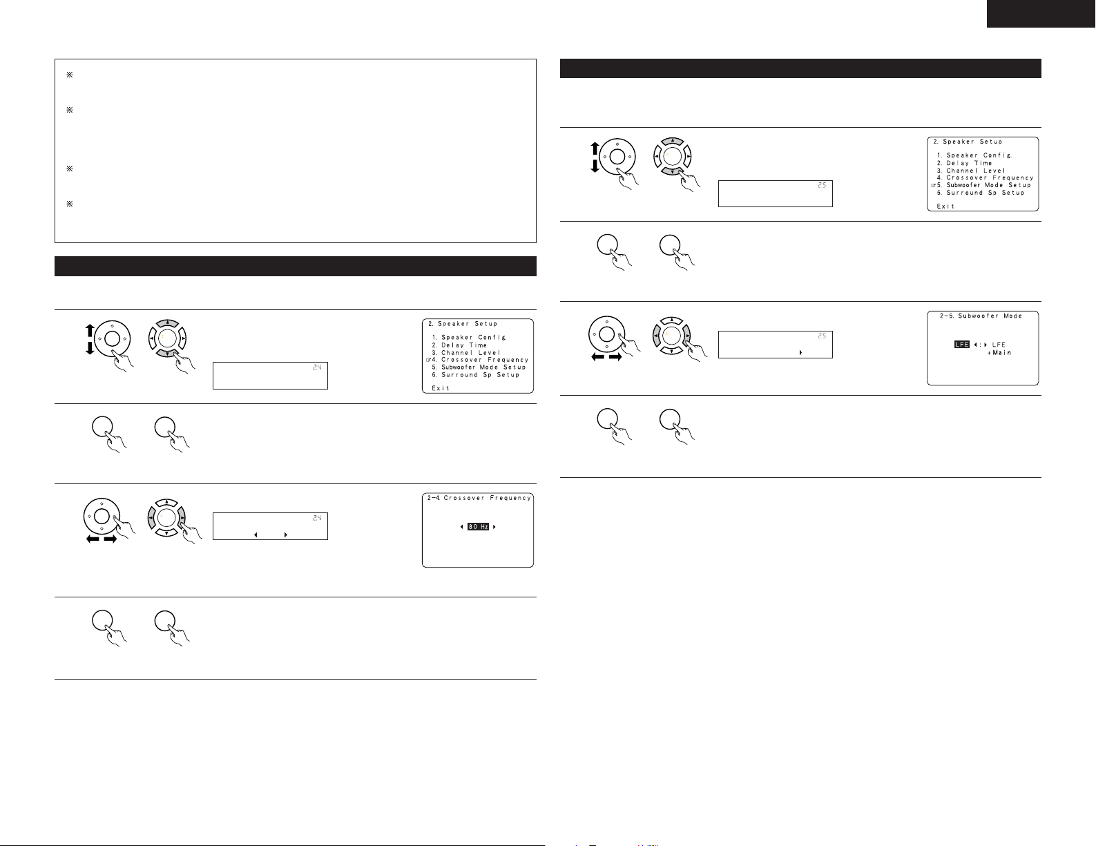
ENGLISH
CH SEL
ENTER
CH SEL
ENTER
Crossover Freq.
*Speaker Setup
CH SEL
ENTER
CH SEL
ENTER
CH SEL
ENTER
CH SEL
ENTER
80Hz
*Crossover Freq
CH SEL
ENTER
CH SEL
ENTER
CH SEL
ENTER
CH SEL
ENTER
Subwoofer Mode
*Speaker Setup
CH SEL
ENTER
CH SEL
ENTER
CH SEL
ENTER
CH SEL
ENTER
LFE
*Subwoofer Mode
CH SEL
ENTER
CH SEL
ENTER
When you adjust the channel levels while in the SYSTEM SETUP CHANNEL LEVEL mode, the channel
level adjustments made will affect all surround modes. Consider this mode a Master Channel Level
adjustment mode.
After you have completed the SYSTEM SETUP CHANNEL LEVEL adjustments, you can then activate the
individual surround modes and adjust channel levels that will be remembered for each of those modes.
Then, whenever you activate a particular surround sound mode, your preferred channel level adjustments
for just that mode will be recalled. Check the instructions for adjusting channel levels within each
surround mode. (See page 41)
You can adjust the channel levels for each of the following surround modes: PURE DIRECT/DIRECT,
STEREO, DOLBY/DTS SURROUND, 5/7 CH STEREO, WIDE SCREEN, SUPER STADIUM, ROCK ARENA,
JAZZ CLUB, CLASSIC CONCERT, MONO MOVIE, VIDEO GAME, MATRIX and VIRTUAL.
When using either surround speakers A or B, or when using surround speakers A and B at the same time,
be sure to adjust the balance of playback levels between each channel for the various selections of “A
or B” and “A and B”.
2-4 Setting the crossover frequency
• Set the crossover frequency mode according to the speaker system being used.
1
unit)
(Main unit)(Remote control
2
unit)
(Main unit)(Remote control
Select the “Crossover Frequency” at the
Speaker Setup Menu.
Display the Crossover Frequency screen.
2-5 Setting the low frequency distribution
This screen is not displayed when not using a subwoofer and all speakers are set to small size.
• Set the subwoofer mode according to the speaker system being used.
1
unit)
(Main unit)(Remote control
2
unit)
(Main unit)(Remote control
3
unit)
(Main unit)(Remote control
4
unit)
(Main unit)(Remote control
Select the “Subwoofer Mode Setup” at the
Speaker Setup Menu.
Display the Subwoofer Mode screen.
Select the setting.
Enter the setting.
The Speaker Setup Menu reappears.
3
4
unit)
unit)
Select the frequency.
(Main unit)(Remote control
• 40 / 60 / 80 / 100 / 120 / 150 / 200 / 250 Hz
can be selected.
Enter the setting.
The Speaker Setup Menu reappears.
(Main unit)(Remote control
21
Page 22
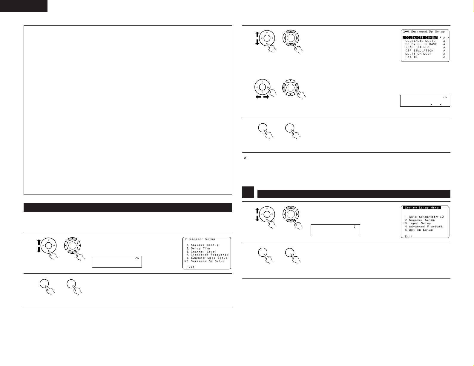
ENGLISH
CH SEL
ENTER
CH SEL
ENTER
Surr Sp Setup
*Speaker Setup
CH SEL
ENTER
CH SEL
ENTER
CH SEL
ENTER
CH SEL
ENTER
CINEMA : A
*Surr Sp Setup
CH SEL
ENTER
CH SEL
ENTER
CH SEL
ENTER
CH SEL
ENTER
CH SEL
ENTER
CH SEL
ENTER
CH SEL
ENTER
CH SEL
ENTER
Input Setup
*System Setup
NOTES:
— Assignment of low frequency signal range (2-1) —
• The only signals produced from the subwoofer channel are LFE signals (during playback of Dolby Digital or
DTS signals) and the low frequency signal range of channels set to “SMALL” in the setup menu. The low
frequency signal range of channels set to “LARGE” are produced from those channels.
— Crossover Frequency (2-4) —
• When “Subwoofer” is set to “Ye s ” at the “Speaker Configuration Setting”, set the frequency (Hz) below
which the bass sound of the various speakers is to be output from the subwoofer (the crossover
frequency).
• For speakers set to “Small”, sound with a frequency below the crossover frequency is cut, and the cut
bass sound is output from the subwoofer instead.
(• When the subwoofer set to “NO”, the bass sound is output from the speaker set as “Large”.)
NOTE: For ordinary speaker systems, we recommend setting the crossover frequency to 80 Hz. When
using small speakers, however, setting the crossover frequency to a high frequency may improve
frequency response for frequencies near the crossover frequency.
— Subwoofer mode (2-5) —
• The subwoofer mode setting is only valid when “LARGE” is set for the front speakers and “YES” is set
for the subwoofer in the “Setting the type of speakers”. (see page 18).
• When the “LFE+MAIN” playback mode is selected, the low frequency signal range of channels set to
“LARGE” are produced simultaneously from those channels and the subwoofer channel.
In this playback mode, the low frequency range expand more uniformly through the room, but depending
on the size and shape of the room, interference may result in a decrease of the actual volume of the low
frequency range.
• Selection of the “LFE ” play mode will play the low frequency signal range of the channel selected with
“LARGE” from that channel only. Therefore, the low frequency signal range that are played from the
subwoofer channel are only the low frequency signal range of LFE (only during Dolby Digital or DTS signal
playback) and the channel specified as “SMALL” in the setup menu.
• Select the play mode that provides bass reproduction with quantity.
• When the subwoofer is set to “Ye s ”, bass sound is output from the subwoofer regardless of the
subwoofer mode setting in surround modes other than Dolby/DTS.
• In surround modes other than Dolby Digital and DTS, if the subwoofer is set to “YES”, the low frequency
portion is always output to the subwoofer channel. For details, refer to “Surround Modes and
Parameters”. (See page 61)
3
q To select the surround mode
When either “Large” or “Small” has been
set for both speakers A and B on the
System Setup Menu (when using both A
and B surround speakers), the surround
speaker setting screen appears.
Select the surround speakers to be used
unit)
(Main unit)(Remote control
in each surround mode.
w To select the surround speaker
A : When surround speakers A is
used.
B : When surround speakers B is
unit)
4
(Main unit)(Remote control
Enter the setting.
At the “2. Speaker Setup ”screen, select “Exit” and press the ENTER
used.
A+B : When both surround speakers A
and B are used.
button.
The System Setup Menu reappears.
unit)
(Main unit)(Remote control
Speaker type setting when using both surround speakers A and B
If “Small” is set for either surround speakers A or B, the output is the same as when “Small” is set for both
A and B.
Setting the Input Setup
3
2-6 Selecting the Surround Speakers for the different surround modes
This Menu is displayed when both surround speakers A and B are used.
• At this screen preset the surround speakers to be used in each surround modes.
1
2
22
unit)
unit)
1
Select “Surround Sp Setup” at the Speaker
Setup Menu.
(Remote control
unit)
(Main unit)
2
(Main unit)(Remote control
(Remote control
unit)
(Main unit)
At the System Setup Menu select “Input
Setup”.
Display the Input Setup Menu screen.
Display the Surround Sp Setup screen.
(Main unit)(Remote control
Page 23
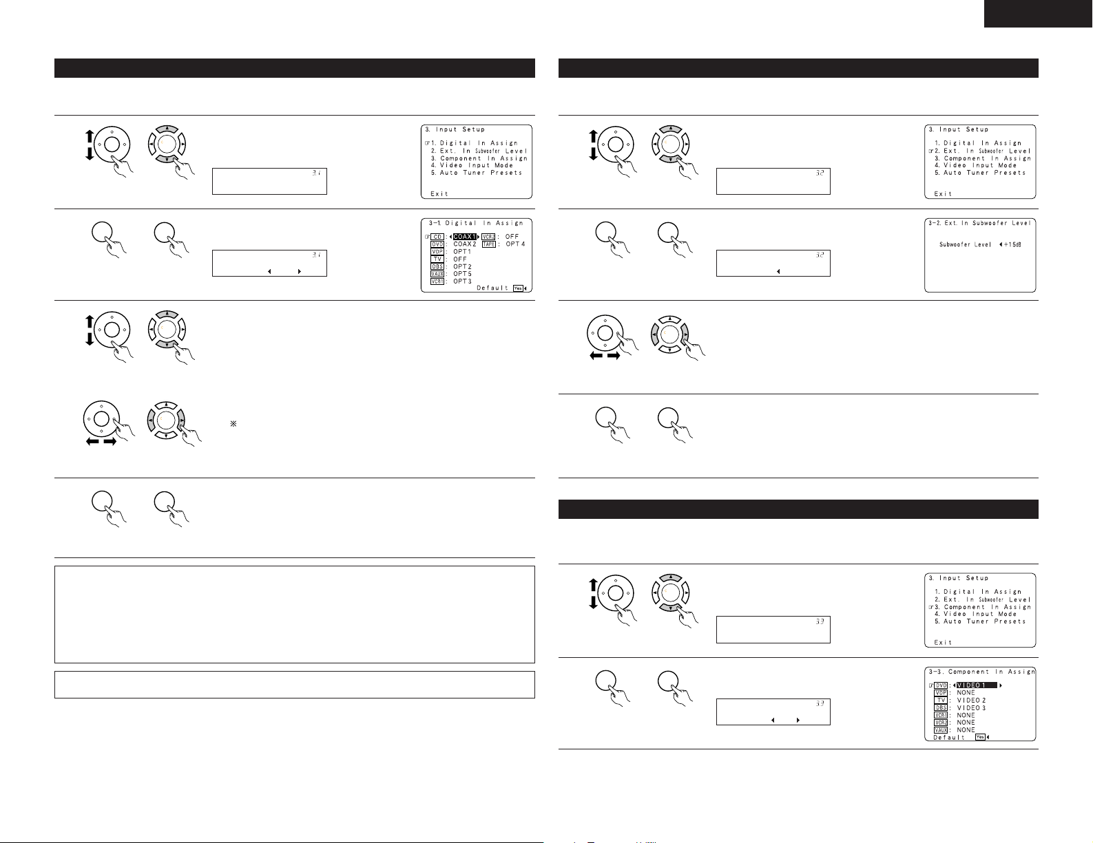
ENGLISH
CH SEL
ENTER
CH SEL
ENTER
Digital In
*Input Setup
CH SEL
ENTER
CH SEL
ENTER
CD : COAX1
*Digital In
CH SEL
ENTER
CH SEL
ENTER
CH SEL
ENTER
CH SEL
ENTER
CH SEL
ENTER
CH SEL
ENTER
CH SEL
ENTER
CH SEL
ENTER
Ext.In SW Lev.
*Input Setup
CH SEL
ENTER
CH SEL
ENTER
SW Lev.: +15dB
*Ext.In SW Lev.
CH SEL
ENTER
CH SEL
ENTER
CH SEL
ENTER
CH SEL
ENTER
CH SEL
ENTER
CH SEL
ENTER
Component In
*Input Setup
CH SEL
ENTER
CH SEL
ENTER
DVD : V1
*Component In
3-1 Setting the Digital In Assignment
• This setting assigns the digital input jacks of the AVR-3805 for the different input sources.
1
unit)
(Main unit)(Remote control
2
unit)
(Main unit)(Remote control
3
unit)
unit)
(Main unit)(Remote control
(Main unit)(Remote control
At the Input Setup Menu select “Digital In
Assign”.
Display the Digital Inputs screen.
Select the digital input jack to be assigned to the input source.
q Select the input source
w Select the digital input jack
Select “OFF” for input sources for which no digital input jacks are used.
If “Ye s ” is selected for “Default”, the settings are automatically
reset to the default values.
3-2 Setting the Ext. In Subwoofer Level
• Set the method of playback of the analog input signal connected to the Ext.In Subwoofer.
1
unit)
(Main unit)(Remote control
2
unit)
(Main unit)(Remote control
3
unit)
(Main unit)(Remote control
4
unit)
(Main unit)(Remote control
Select “Ext.In Subwoofer Level” at the Input
Setup Menu.
Display to the Ext.In Subwoofer Level screen.
Select the desired setting.
Select according to the specifications of the player being used. Also refer to
the player’s operating instructions.
+15 dB (default) recommended. (0, +5, +10 or +15 can be selected.)
Enter the setting.
The Input Setup Menu reappears.
4
NOTES:
• The OPTICAL 3, 4 jacks on the AVR-3805’s rear panel are equipped with an optical digital output jack for
recording digital signals on a CD recorder, MD recorder or other digital recorder. Use this for digital recording
between a digital audio source (stereo - 2 channel) and a digital audio recorder.
• Do not connect the output of the component connected to the OPTICAL 3, 4 OUT jack on the AVR-3805’s
rear panel to any jack other than the OPTICAL 3, 4 IN jack.
•“PHONO” and “TUNER” cannot be selected on the Digital In Assignment.
Refer to “DENON LINK connections”. (See page 8)
unit)
Enter the setting.
The Input Setup Menu reappears.
(Main unit)(Remote control
3-3 Setting the Component In Assign
• This setting assigns the color difference (component) video input jacks of the AVR-3805 for the different input
sources.
1
unit)
(Main unit)(Remote control
2
unit)
(Main unit)(Remote control
Select “Component In Assign” at the Input
Setup Menu.
Display the Component In Assign screen.
23
Page 24
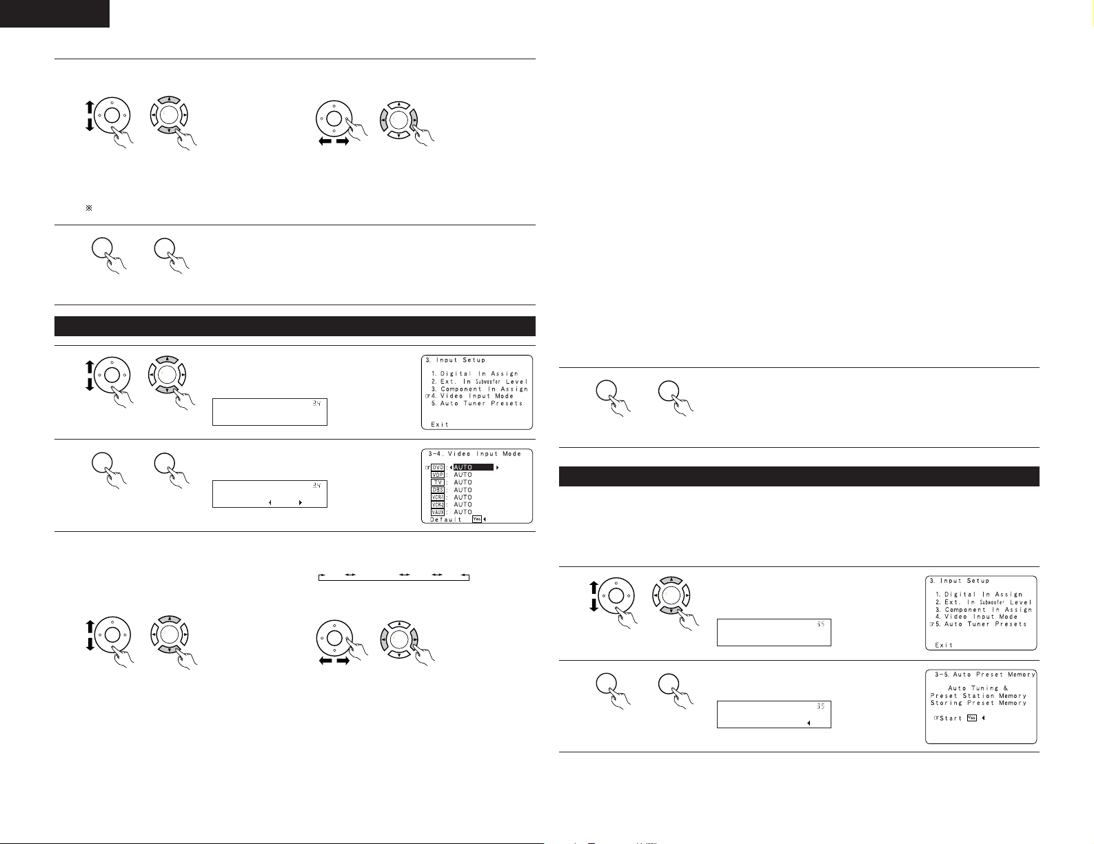
ENGLISH
CH SEL
ENTER
CH SEL
ENTER
CH SEL
ENTER
CH SEL
ENTER
CH SEL
ENTER
CH SEL
ENTER
CH SEL
ENTER
CH SEL
ENTER
Video In Mode
*Input Setup
CH SEL
ENTER
CH SEL
ENTER
DVD : Auto
*Video In Mode
CH SEL
ENTER
CH SEL
ENTER
CH SEL
ENTER
CH SEL
ENTER
AUTO
COMPONENT
Svideo Video
CH SEL
ENTER
CH SEL
ENTER
CH SEL
ENTER
CH SEL
ENTER
Auto Tuner
*Input Setup
CH SEL
ENTER
CH SEL
ENTER
Start :Yes
*Auto Tuner
Select the component (Y, PB/CB and PR/CR) video input terminal to be assigned to the input source.
3
q Select the source
selection.
w Select the
component video
input terminal.
unit)
(Main unit)(Remote control
unit)
(Main unit)(Remote control
Select “NONE” for sources for which the component (Y, PB/CB and PR/CR) video input is not to be used.
When the default, “Ye s”, is selected, the settings are reset to the factory defaults.
4
unit)
(Main unit)(Remote control
Enter the setting.
The Input Setup Menu reappears.
3-4 Setting the Video Input Mode
1
unit)
(Main unit)(Remote control
2
unit)
q Select the input source for which you want
3
to set the Video Input Mode.
(Main unit)(Remote control
Select “Video Input Mode” at the Input Setup
Menu.
Display the Video Input Mode screen.
w Select the mode as below.
The details in each mode are as follows.
AUTO: When there are multiple input signals, the input signals are detected and the input signal
to be output from the video monitor output terminal is selected automatically in the
following order: component video, S-Video, composite video.
Component: The signal connected to the component video terminal is always played.
Video conversion is not conducted, so no image is output from the monitor output terminal
when there is no input signal to the component terminal.
S-Video: The signal connected to the S-Video terminal is always played.
The S-Video input signal is converted and output from the composite and component
monitor output terminal.
Video: The signal connected to the composite video terminal is always played.
The composite video input signal is up-converted and output from the S-Video and
component monitor output terminals.
NOTE:
Down-converting from the component video signal to the S-Video and composite video signal is not
possible, so when not using the component video monitor output terminal connect the player using the
S-Video or composite video input terminal.
Cautions on the video conversion function:
When the component video terminals are used to connect the AVR-3805 with a TV (or monitor, projector,
etc.) and the video (yellow) or S video terminals are used to connect the AVR-3805 with a VTR, depending
on the combination of the TV and VTR the picture may flicker in the horizontal direction, be distorted, be
out of sync or not display at all when playing video tapes.
If this happens, connect a commercially available video stabilizer, etc., with a TBC (time base corrector)
function between the AVR-3805 and the VTR, or if your VTR has a TBC function, turn it on.
4
unit)
(Main unit)(Remote control
Enter the setting.
The System Setup Menu reappears.
3-5 Auto Tuner Presets
Use this to automatically search for FM broadcasts and store up to 56 stations at preset channels A1 to 8, B1
to 8, C1 to 8, D1 to 8, E1 to 8, F1 to 8 and G1 to 8.
NOTE:
• If an FM station cannot be preset automatically due to poor reception, use the “Manual tuning” operation to
tune in the station, then preset it using the manual “Preset memory” operation.
1
Select “Auto Tuner Presets”at the Input
Setup Menu.
24
unit)
unit)
(Main unit)(Remote control
unit)
(Main unit)(Remote control
2
unit)
(Main unit)(Remote control
Display the Auto Preset Memory screen.
(Main unit)(Remote control
Page 25
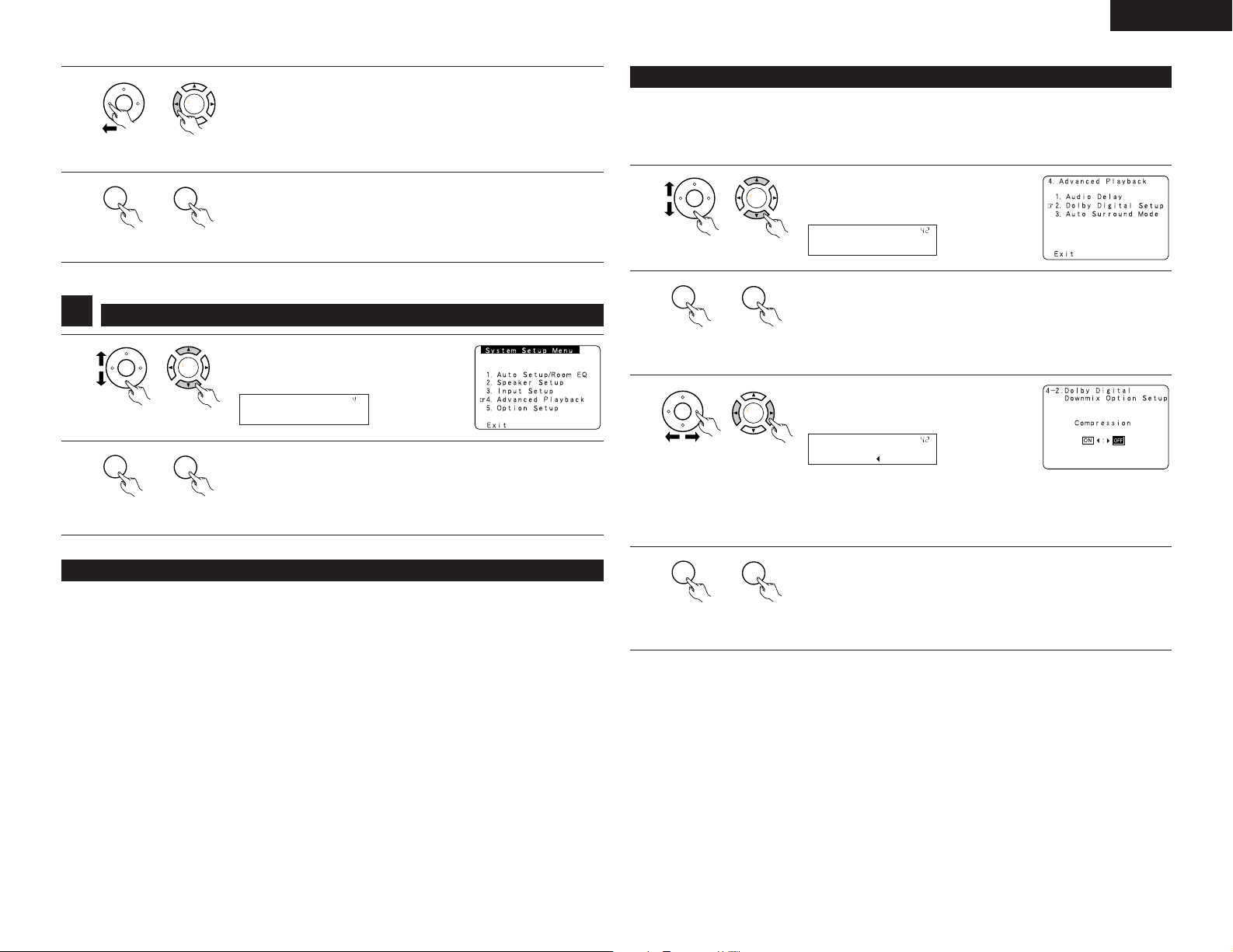
ENGLISH
CH SEL
ENTER
CH SEL
ENTER
CH SEL
ENTER
CH SEL
ENTER
CH SEL
ENTER
CH SEL
ENTER
CH SEL
ENTER
CH SEL
ENTER
Advanced Play
*System Setup
CH SEL
ENTER
CH SEL
ENTER
Dolby D Setup
*Advanced Play
CH SEL
ENTER
CH SEL
ENTER
CH SEL
ENTER
CH SEL
ENTER
Comp. : OFF
*Dolby D Setup
CH SEL
ENTER
CH SEL
ENTER
3
4
4
1
2
Press the CURSOR left button to select “Ye s”.
“Search” flashes on the screen and searching begins.
“Completed” appears once searching is completed.
The display automatically switches to screen.
unit)
(Main unit)(Remote control
Enter the setting.
The Input Setup Menu reappears.
unit)
(Main unit)(Remote control
Setting the Advanced Playback
Select “Advanced Play back” at the System
Setup Menu.
(Remote control
unit)
(Remote control
unit)
(Main unit)
Display the Advanced Playback Menu screen.
(Main unit)
4-2 Setting the Dolby Digital Setup
Sets the down-mixing method when not using a center speaker or surround speakers.
OFF: The dynamic range is not compressed.
ON: The dynamic range is compressed automatically according to the combination of speakers being
used.
1
unit)
(Main unit)(Remote control
2
unit)
(Main unit)(Remote control
3
unit)
NOTE:
When a center speaker or surround speakers, are not used the sound is played from the front speakers.
Set “Compression” to “ON” if it seems that sound is distorted because the input level exceeds the allowable
input for the front speakers.
(Main unit)(Remote control
Select “Dolby Digital Setup” at the Advanced
Playback Menu.
Press the ENTER button.
Display the Dolby Digital Setup screen.
Select “ON” if you want to use the
Compression, “OFF” if you do not want to
use it.
4-1 Setting the Audio Delay
This function allows you to adjust the time delay of the video and audio signals and store these settings for the
different input sources.
The setting is made while watching a DVD or other software, so it is not made here.
By default, this is not displayed when no digital signals are being input.
For instructions on making the setting, refer to page 36.
NOTE:
The audio delay setting does not apply when it plays in the EXT. IN mode or in the analog input direct mode or
stereo mode (TONE DEFEAT “ON”).
4
unit)
(Main unit)(Remote control
Enter the setting.
The Advanced Playback Menu reappears.
25
Page 26
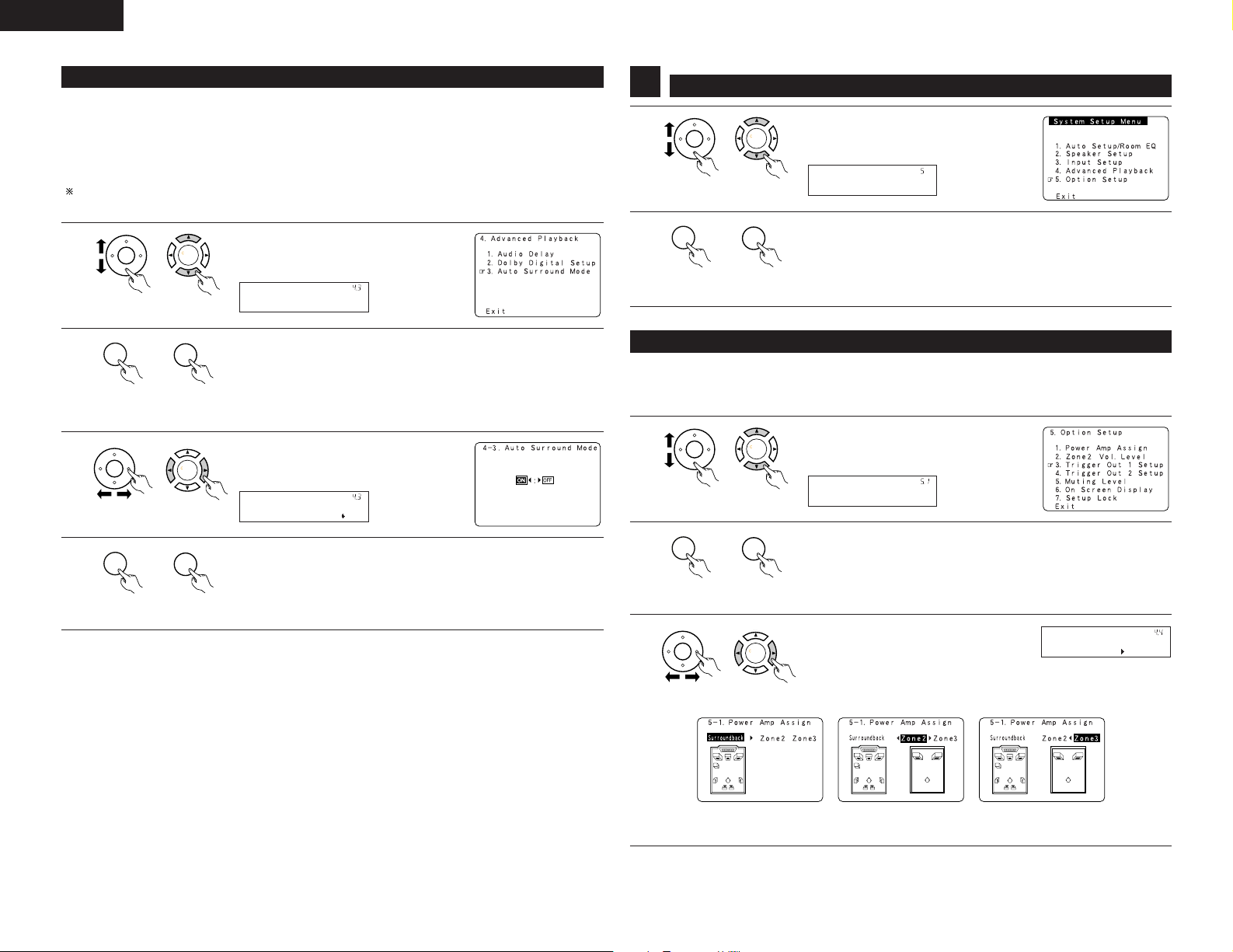
ENGLISH
CH SEL
ENTER
CH SEL
ENTER
Auto Surround
*Advanced Play
CH SEL
ENTER
CH SEL
ENTER
CH SEL
ENTER
CH SEL
ENTER
ON/OFF: ON
*Auto Surround
CH SEL
ENTER
CH SEL
ENTER
CH SEL
ENTER
CH SEL
ENTER
CH SEL
ENTER
CH SEL
ENTER
Option Setup
*System Setup
CH SEL
ENTER
CH SEL
ENTER
P.Amp Assign
*Option Setup
CH SEL
ENTER
CH SEL
ENTER
CH SEL
ENTER
CH SEL
ENTER
S.Back
*P.Amp Assign
4-3 Setting the Auto Surround Mode
The surround mode used at last for the three types of input signals shown below is stored in the memory, and
the signal is automatically played with that surround mode the next time it is input.
Note that the surround mode setting is also stored separately for the different input sources.
q Analog and PCM 2-channel signals
w 2-channel signals of Dolby Digital, DTS or other multi-channel format
e Multi-channel signals of Dolby Digital, DTS or other multi-channel format
During playback in the PURE DIRECT mode, the surround mode does not change even if the input signal is
changed.
1
unit)
(Main unit)(Remote control
2
unit)
(Main unit)(Remote control
3
unit)
(Main unit)(Remote control
4
unit)
(Main unit)(Remote control
Select “Auto Surround Mode” at the
Advanced Playback Menu.
Press the ENTER button.
Display the Auto Surround Mode screen.
Select “ON” if you want to use the auto
surround mode, “OFF” if you do not want to
use it.
Enter the setting.
The Advanced Playback Menu reappears.
Setting the Option Setup
5
1
2
(Remote control
unit)
(Remote control
unit)
(Main unit)
(Main unit)
Select “Option Setup” at the System Setup
Menu.
Display the Option Setup Menu Screen.
5-1 Setting the Power Amplifier Assignment
Make this setting to switch the power amplifier for the surround back channel to ZONE2 or ZONE3.
If ZONE2/3 is selected, the signal that selected at ZONE2/3 is output at “SURR. BACK/MULTI ZONE PREOUT”
terminals.
1
unit)
(Main unit)(Remote control
2
unit)
(Main unit)(Remote control
3
Select “Power Amp Assign” at the Option
Setup Menu.
Press the ENTER button.
Display the Power Amp Assign screen.
Select “Surround Back” to use as the
surround back channel, “Zone2” to use as
Zone2 out, Zone3 to use as Zone3 out.
26
unit)
(Main unit)(Remote control
When “Surround Back” is
selected
When “Zone2” is
selected
When “Zone3” is
selected
Page 27
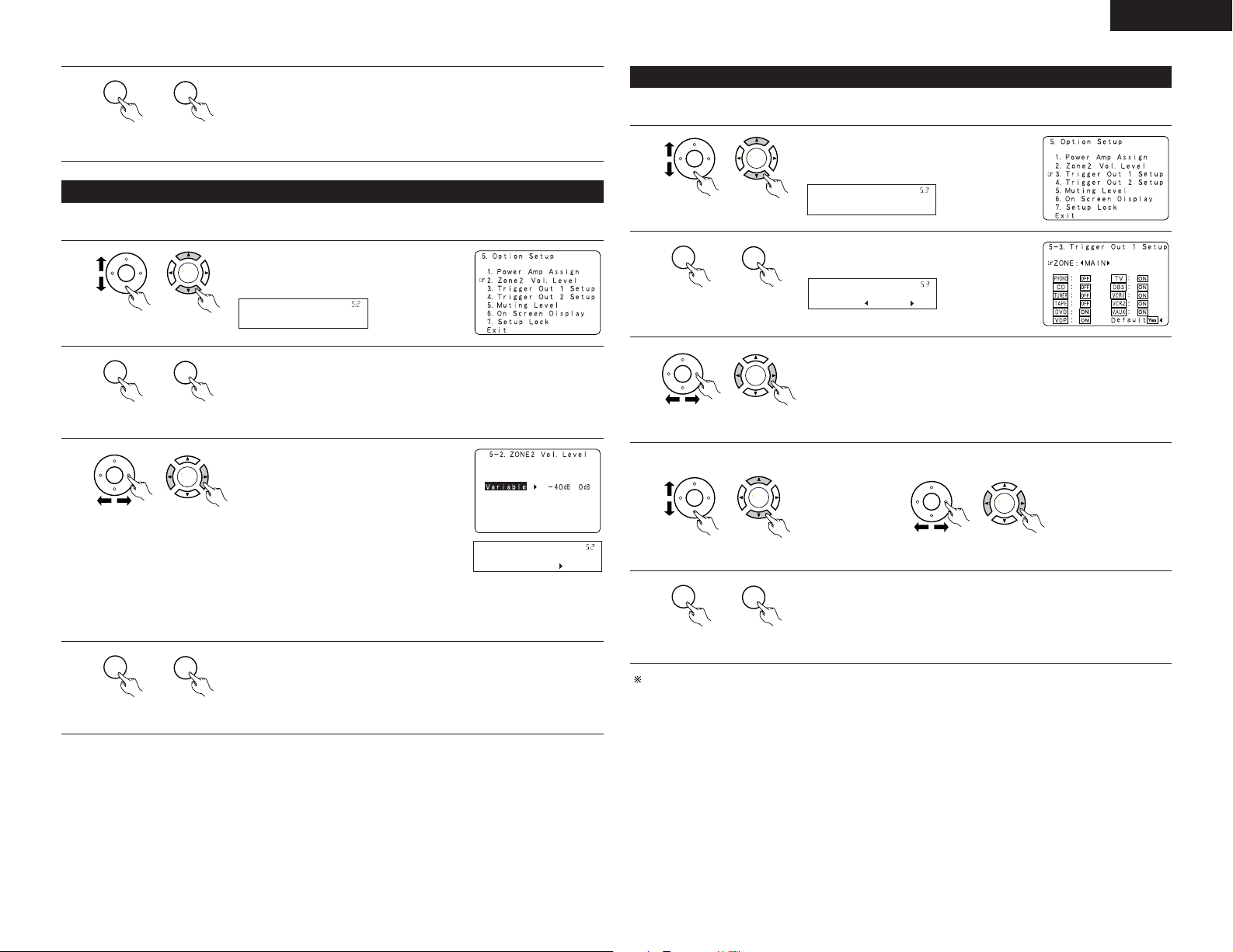
ENGLISH
CH SEL
ENTER
CH SEL
ENTER
CH SEL
ENTER
CH SEL
ENTER
Zone2 Vol.Level
*Option Setup
CH SEL
ENTER
CH SEL
ENTER
CH SEL
ENTER
CH SEL
ENTER
Variable
*Zone2 Vol.Lev.
CH SEL
ENTER
CH SEL
ENTER
CH SEL
ENTER
CH SEL
ENTER
Trigger Out 1
*Option Setup
CH SEL
ENTER
CH SEL
ENTER
CH SEL
ENTER
CH SEL
ENTER
ZONE : MAIN
*Trigger Out 1
CH SEL
ENTER
CH SEL
ENTER
CH SEL
ENTER
CH SEL
ENTER
CH SEL
ENTER
CH SEL
ENTER
4
unit)
(Main unit)(Remote control
Enter the setting.
The Option Setup Menu reappear.
5-2 Setting the Zone2 Vol. Level
Set the Zone2 pre-out output level adjustment.
1
unit)
(Main unit)(Remote control
2
unit)
(Main unit)(Remote control
3
unit)
(Main unit)(Remote control
4
At the Option Setup Menu select “Zone2
Vol.Level”.
Display the Zone2 Vol. Level screen.
Select the desired setting.
Variable:
The level can be adjusted freely using the
buttons on the remote control unit.
0 dB, –40 dB:
The output level is fixed at the set level and
the volume can no longer be adjusted.
NOTE:
• When “ZONE2” is selected at System
Setup Menu “5-1. Power amp Assign”, the
Zone2 vol. Level is all set to “variable”
including preout level and this menu is not
displayed.
Enter the setting.
The Option Setup Menu reappears.
5-3, 5-4 Setting the Trigger Out Setup
• Set the Trigger Out output 1 for the different input sources.
1
unit)
(Main unit)(Remote control
2
unit)
(Main unit)(Remote control
3
unit)
q Select the input source. w Select “ON” or “OFF”.
4
unit)
(Main unit)(Remote control
(Main unit)(Remote control
5
unit)
Set the Trigger out 2 Setup in the same way.
(Main unit)(Remote control
Select “Trigger Out 1 Setup” at the Option
Setup Menu.
Display to the Trigger Out 1 Setup screen.
Select the Zone (MAIN, Zone2 or Zone3).
unit)
Enter the setting
The Option Setup Menu reappears.
(Main unit)(Remote control
unit)
(Main unit)(Remote control
27
Page 28
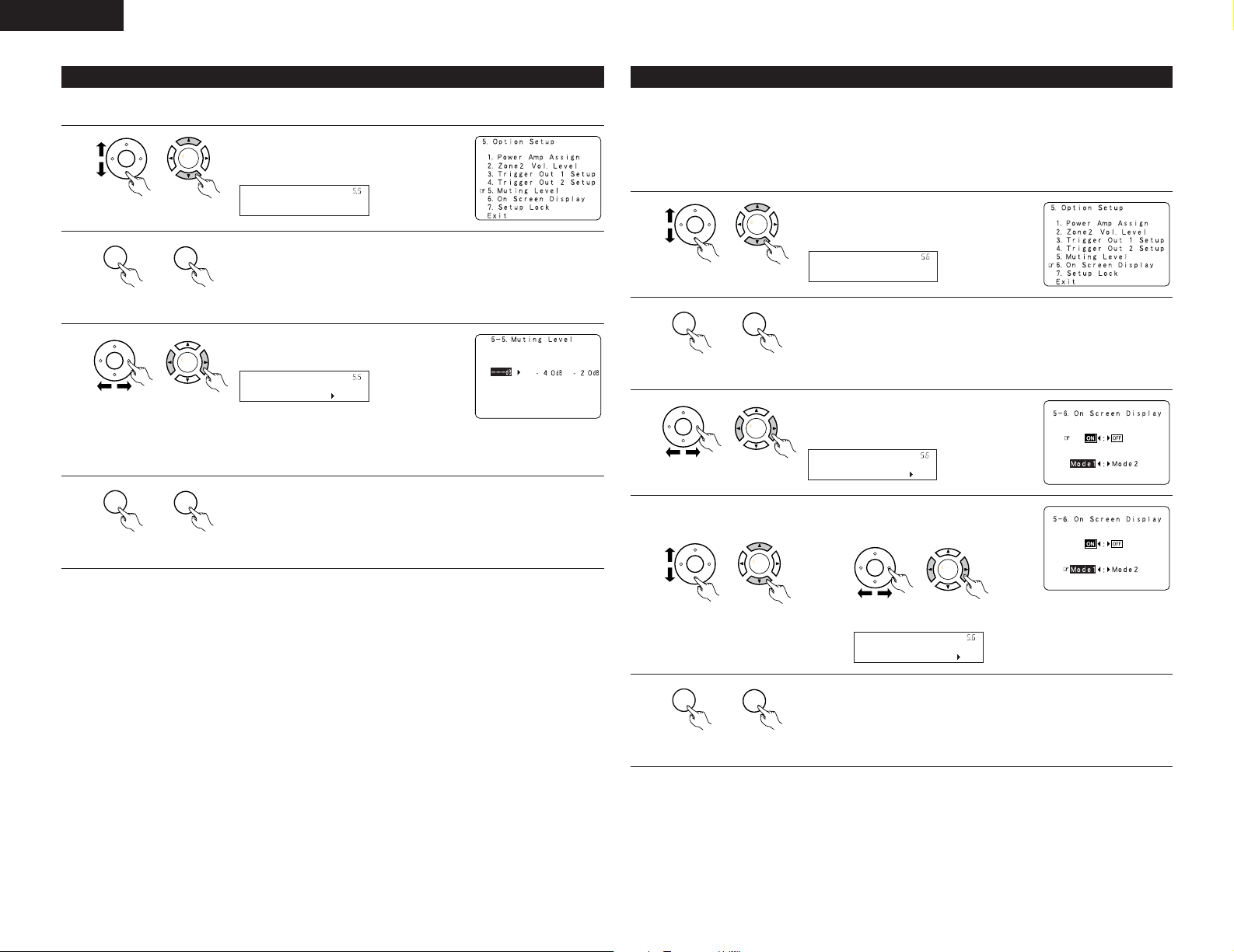
ENGLISH
CH SEL
ENTER
CH SEL
ENTER
Muting Level
*Option Setup
CH SEL
ENTER
CH SEL
ENTER
CH SEL
ENTER
CH SEL
ENTER
---dB
*Muting Level
CH SEL
ENTER
CH SEL
ENTER
CH SEL
ENTER
CH SEL
ENTER
On Screen
*Option Setup
CH SEL
ENTER
CH SEL
ENTER
CH SEL
ENTER
CH SEL
ENTER
ON/OFF: ON
*On Screen
CH SEL
ENTER
CH SEL
ENTER
CH SEL
ENTER
CH SEL
ENTER
Mode : Mode1
*On Screen
CH SEL
ENTER
CH SEL
ENTER
5-5 Setting the Muting Level
• This sets the amount of attenuation at audio output muting.
1
unit)
(Main unit)(Remote control
2
unit)
(Main unit)(Remote control
3
unit)
(Main unit)(Remote control
4
unit)
(Main unit)(Remote control
Select “Muting Level” at the Option Setup
Menu.
Display the Muting Level screen.
Select the desired setting.
•–20 dB: It is turned down the volume to
–20 dB from the present level.
•–40 dB: It is turned down the volume to
–40 dB from the present level.
Enter the setting.
The Option Setup Menu reappears.
5-6 Setting the On Screen Display (OSD)
• Use this to turn the on-screen display (messages other than the menu screens) on or off.
• Sets the on-screen display’s display mode.
Mode 1: Prevents flickering of the on-screen display when there is no video signal.
Mode 2: Flickering is not prevented.
1
2
3
q Select the On Screen Display
4
Use this mode if the on-screen display does not appear in the mode 1, as may happen according
to the TV being used.
Select “On Screen Display” at the Option
Setup Menu.
unit)
(Main unit)(Remote control
Display the On screen display setup screen.
unit)
(Main unit)(Remote control
Select “ON” or “OFF”.
unit)
(Main unit)(Remote control
w Select “Mode1” or “Mode2”.
mode.
28
unit)
5
unit)
(Main unit)(Remote control
unit)
Enter the setting.
The Option Setup Menu reappears.
(Main unit)(Remote control
(Main unit)(Remote control
Page 29
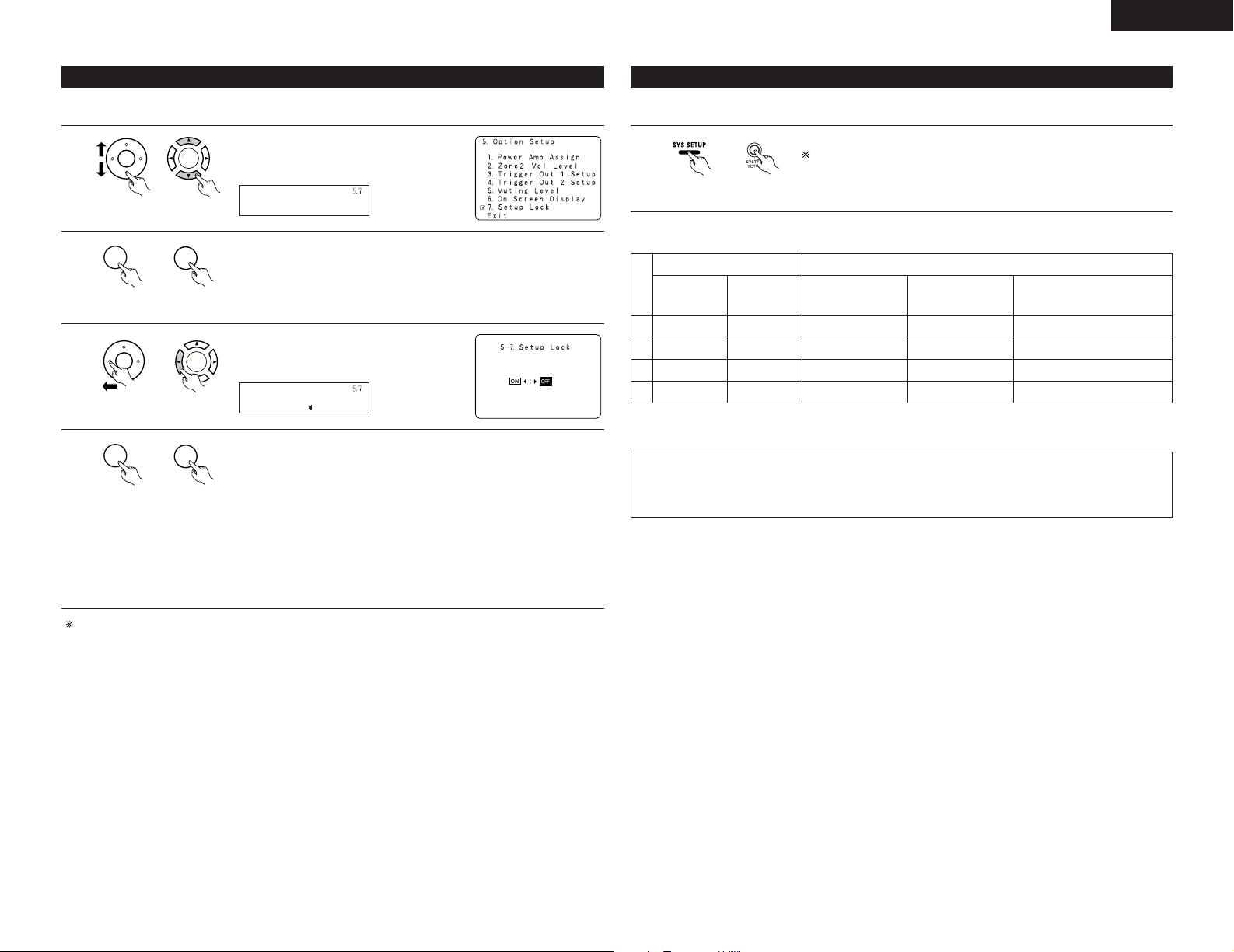
ENGLISH
CH SEL
ENTER
CH SEL
ENTER
Setup Lock
*Option Setup
CH SEL
ENTER
CH SEL
ENTER
CH SEL
ENTER
CH SEL
ENTER
ON/OFF: OFF
*Setup Lock
CH SEL
ENTER
CH SEL
ENTER
5-7 Protecting the setting
The system setup settings can be locked so that they cannot be changed easily.
1
unit)
(Main unit)(Remote control
2
unit)
(Main unit)(Remote control
3
unit)
(Main unit)(Remote control
4
unit)
(Main unit)(Remote control
Select “Setup Lock” at the Option Setup
Menu.
Display the Setup Lock screen.
Select “ON”, to lock the system setup
settings.
Press the “ENTER”button to finalize the setting and exit the Option setup
mode.
When the setup lock function is activated, the settings listed below cannot
be changed, and “Setup Locked” is displayed when related buttons are
operated.
• System setup settings
• Surround parameter settings
• Tone control settings
• Channel level settings (including test tones)
To unlock, press the System Setup button again and display the Setup Lock
screen, then select “OFF” and press “ENTER”.
After completing system setup
This button can be pressed at any time during the system setup process to complete the process.
1
unit)
• On-screen display signals
Signals input to the AVR-3805 On-screen display signal output
VIDEO signal
input jack
(yellow)
1
2
3
4
(C: Signal
E
C
E
C
:
E
NOTE:
• When a component video signal is input and when the “Video Input Mode” is set to the component fixed
mode at Input setup, the on-screen display is only displayed when the System Setup, Surround
Parameters and On Screen buttons are operated.
(Main unit)(Remote control
S-video signal
input jack
No signal)(
Press the SYSTEM SETUP button at the System Setup Menu.
The changed settings are entered and the on-screen display turns off.
Video signal output to
VIDEO MONITOR OUT
jack (yellow)
E
E
C
C
C
C
C
E
: On-screen signals output
C
Video signal output to
S-Video MONITOR
OUT jack
C
C
C
C
:
On-screen signals not output)
E
Video signal output to Color
Difference (Component) Video
MONITOR OUT jack
C
C
C
C
System setup is complete. Once these settings are made, there is no need to change them unless
different AV components are connected or the speakers are repositioned.
29
Page 30
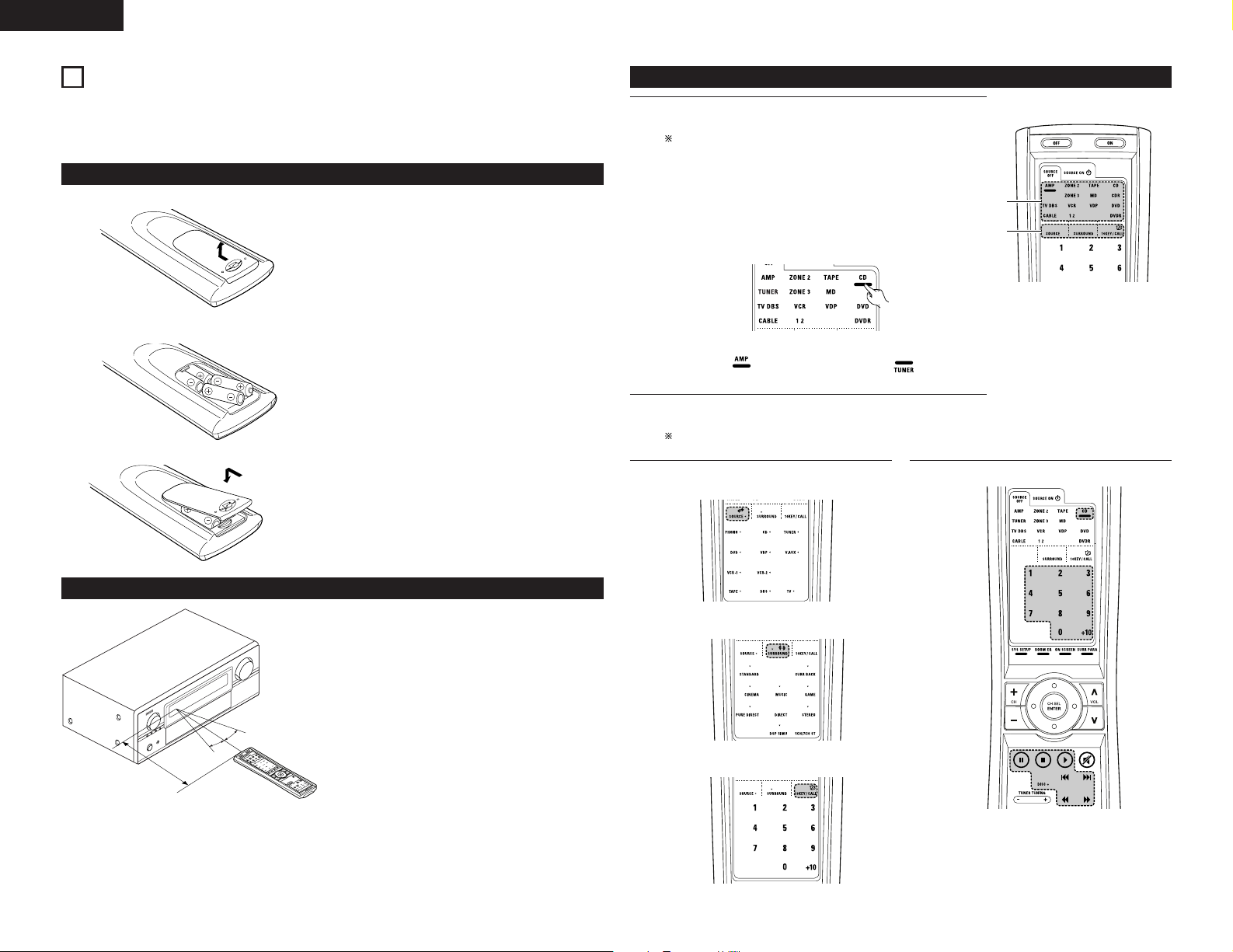
ENGLISH
CH
S
E
L
EN
TER
1
3
8
REMOTE CONTROL UNIT
• The included remote control unit (RC-970) can be used to operate not only the AVR-3805 but other remote
control compatible DENON components as well. In addition, the memory contains the control signals for
other remote control units, so it can be used to operate non-DENON remote control compatible products.
Inserting the batteries
q Remove the remote control unit’s rear cover.
w Set three R03/AAA batteries in the battery
compartment in the indicated direction.
e Put the rear cover back on.
Notes on Batteries
• Use R03/AAA batteries in the remote control unit.
• The batteries should be replaced with new ones
approximately once a year, though this depends on
the frequency of usage.
• Even if less than a year has passed, replace the
batteries with new ones if the set does not operate
even when the remote control unit is operated
nearby the set. (The included battery is only for
verifying operation. Replace it with a new battery as
soon as possible.)
• When inserting the batteries, be sure to do so in the
proper direction, following the “≈” and “√” marks
in the battery compartment.
• To prevent damage or leakage of battery fluid:
• Do not use a new battery together with an old
one.
• Do not use two different types of batteries.
• Do not short-circuit, disassemble, heat or
dispose of batteries in flames.
• Remove the batteries from the remote control unit
when you do not plan to use it for an extended
period of time.
• If the battery fluid should leak, carefully wipe the
fluid off the inside of the battery compartment and
insert new batteries.
• When replacing the batteries, have the new
batteries ready and insert them as quickly as
possible.
Operating DENON audio components
Use the mode selector buttons to select the component you want
1
to operate.
The function switches as shown below each time one of the
mode buttons is pressed.
AMP/TUNER : AMP, TUNER
ZONE2/ZONE3 : ZONE2, ZONE3
TAPE/MD : TAPE, MD
CD/CDR : CD, CDR
TV/DBS/CABLE : TV, DBS, CABLE
VCR1/VCR2 : VCR1,VCR2
VDP : VDP
DVD/DVDR : DVD,DVDR
Example: Select “AMP” mode. Select “TUNER” mode.
Operate the audio component.
2
• For details, refer to the component’s operating instructions.
It may not be possible to operate some models.
[SOURCE MENU]
3
• Operate the source.
1. CD player (CD) system buttons
Using the remote control unit
• Point the remote control unit at the remote sensor
on the main unit as shown on the diagram.
• The remote control unit can be used from a straight
distance of approximately 7 meters from the main
unit, but this distance will be shorter if there are
obstacles in the way or if the remote control unit is
not pointed directly at the remote sensor.
• The remote control unit can be operated at a
horizontal angle of up to 30 degrees with respect to
the remote sensor.
Approx. 7 m
30°
30°
NOTES:
• It may be difficult to operate the remote control
unit if the remote sensor is exposed to direct
sunlight or strong artificial light.
• Do not press buttons on the main unit and remote
control unit simultaneously. Doing so may result in
malfunction.
30
• Neon signs or other devices emitting pulse-type
noise nearby may result in malfunction, so keep
the set as far away from such devices as possible.
[SURROUND MENU]
• Operate the surround mode.
[10KEY / SYSTEM CALL MENU]
• Operate the 10KEY or SYSTEM CALL mode.
6, 7 : Manual search (forward and reverse)
2 :Stop
1 : Play
8, 9 : Auto search (to beginning of track)
3 : Pause
DISC SKIP + : (for CD changers only)
0~9, +10 : 10 Key
Page 31

ENGLISH
3
3
1
5
2, 4
CH SEL
ENTER
2. TAPE deck (TAPE) system buttons
3. MD recorder (MD), CD recorder (CDR)
system buttons
6 : Rewind
7 : Fast forward
2 :Stop
1 : Forward Play
3 : Pause
0 : Reverse Play
A/B : Switch between sides A
and B
4. Tuner system buttons
TUNING +, – : Tuning up/down
BAND : Switch between AM
MODE : Switch between AUTO
MEMORY : Preset memory
SHIFT : Switch preset channel
CHANNEL +, – : Preset channel
CHA~G : Preset channel range
1~8 : Preset channel
RDS : RDS search
and FM bands
and MANUAL
range
up/down
Preset memory
The included remote control unit can be used to operate devices of different brands by registering the preset
number corresponding to the brand of your device.
For some models the remote control unit or the device may not operate properly. In this case, use the learning
function (page 33) to store your device’s remote control signals in the included remote control unit.
For instructions on resetting the preset memory, see page 35.
Press the power ON button and the OFF button
1
at the same time.
Press the “1”button to select preset memory.
2
• Setup List
1 : Preset memory
2 : Learning setup
3 : System call
4 : Punch through
5 : Light setup
6 : Reset
Press the Mode button for the component you
3
want to preset, then press ENTER button.
Referring to the included List of Preset Codes,
4
use the number buttons to input the preset
code (a 4-digit number) for the manufacturer of
the component whose signals you want to store
in the memory.
“OK” is displayed when the signals are
5
registered and the mode is terminated.
“FAIL” is displayed when the signals are not
registered, repeat steps 1 to 5.
6, 7 : Manual search (forward and reverse)
2 :Stop
1 : Play
8, 9 : Auto search (to beginning of track)
3 : Pause
0~9, +10 : 10 Key
NOTES:
• Depending on the model and year of manufacture, this function cannot be used for some models, even if
the your device is listed on the included list of preset codes.
• Some manufacturers use more than one type of remote control code. Refer to the included list of preset
codes to change the number and check it out.
The preset codes are as follows upon shipment from the factory and after resetting:
TV, VCR1..................................................................................HITACHI
CD, MD, TAPE, CDR, VDP, DVD, DVDR ..................................DENON
VCR2, DBS...............................................................................SONY
CABLE......................................................................................ABC
To store the codes of another component in the
6
memory, repeat steps 1 to 5.
31
Page 32

ENGLISH
1
Operating a component stored in the preset memory
Press the mode selector button for the
1
component you want to operate.
NOTE:
• For the DVD player remote control buttons,
function names may differ according to
manufacturer. Compare with the remote control
operation of the various components.
Operate the component.
2
• For details, refer to the component’s
operating instructions.
Some models cannot be operated with this
remote control unit.
1. Digital video disc player (DVD),
Digital video disc recorder (DVD R) system
buttons
SOURCE ON : Power on
SOURCE OFF : Power off (DENON DVD
6, 7 : Manual search
2 :Stop
1 : Play
8, 9 : Auto search
3 : Pause
DISC SKIP + : Disk skip
SETUP : Setup
TOP MENU : Top menu
MENU : Menu
RETURN : Return
•,ª, 0, 1 : Cursor up, down, left
ENTER : Enter
AUDIO : Switch the audio
DISPLAY : Display
SUBTITLE : Switch the subtitle
ANGLE : Switch the angle
0~9, +10 : 10 key
only)
(forward and reverse)
(to beginning of track)
(for DVD changers only)
and right
language
2. Video disc player (VDP) system
buttons
SOURCE ON : Power on/Standby
6, 7 : Manual search
2 :Stop
1 : Play
8, 9 : Auto search (cue)
3 : Pause
0~9, +10 : 10 key
(forward and reverse)
3. Video deck (VCR-1/VCR-2) system buttons
SOURCE ON : Power on/Standby
6, 7 : Manual search
2 :Stop
1 : Play
3 : Pause
0~9, +10 : 10 key
(forward and reverse)
4. Monitor TV (TV),digital broadcast satellite (DBS)
tuner and cable (CABLE) system buttons
SOURCE ON : Power on/Standby
SETUP : Setup
TOP MENU : Top menu
MENU : Menu
RETURN : Return
•,ª, 0, 1 : Cursor up,down,left and right
ENTER : Enter
DISPLAY : Switch display
Channel +, – : Switch channels +,–
0~9, +10 : 10 key
TV/VCR : Switch between TV and video player
VOL +, – : Volume up/down
32
Page 33

ENGLISH
3, 7
3
1, 8
2
CH SEL
ENTER
CH SEL
ENTER
3, 5
3, 7
1
2, 6, 8
Learning function
If your AV component is not a DENON product or if it cannot be operated using the preset memory, it can be
controlled with the accessorious remote control unit by storing its remote control signals in the remote control
unit.
For some remote control signals it is not possible to “learn” the signals or the device will not operate properly.
In such cases use the remote control unit included with the device to operate it.
Press the power ON button and the OFF button
1
simultaneously.
Press the “2” button to
2
select Learning setup.
Press the Mode button for the component you
3
want to learned, then press the ENTER button.
Learning is not possible for the AMP, ZONE2,
and ZONE3 modes.
System call
The accessorious remote control unit is equipped with “system call” function allowing a series of remote control
signals to be transmitted by pressing a single button.
This function can be used for example to turn on the amplifier’s power, select the input source, turn on the
monitor TV’s power, turn on the source component’s power and set the source to the play mode, all at a signal
button.
(1) System call buttons
Up to 12 signals each can be
stored at the “CALL1” ~
“CALL6” buttons.
The System Call function can
be used in the “AMP”,
“ZONE2”, and “ZONE3”
modes.
(2) Storing system call signals
Press the power ON button and the OFF button
1
at the same time.
Press the “3” button to select system call
2
setting.
Buttons that allow learning will light. Press the
4
button that you wish to be learned. The display
will go off and the unit will enter the learning
standby mode.
• To cancel, press the
power ON button and
the OFF button
simultaneously.
Point the remote control units directly at each
5
other and press and hold in the button on the
other remote control unit which you want to
“learn”.
Other remote
control unit
“OK” appears on the remote control unit’s
6
display and learning is completed.
• Other keys can be “learned” by repeating
steps 5 to 6.
•“FAIL” appears on the remote control unit’s
display, repeating steps 4 to 6.
The mode can be switched by pressing a mode
7
selector button.
The “Buttons that allow learning” display
reappears and the learning standby mode is set.
To cancel the learning mode, press the power
8
ON button and the OFF button simultaneously
again.
Press the Mode button for the component you
3
want to register at the system call button, then
press the ENTER button.
Press the button you want to register.
4
The mode can be switched by pressing a mode
button.
5
Repeat steps 4 and 5 to register the desired
6
buttons.
Up to 12 signals each can bestored at the CALL
1 ~ CALL 6.
Press the ENTER button after the button
7
registration is completed. There will be a
changeover to the System Call registration
screen.
Press buttons from “CALL 1” to “CALL 6” to
8
register the System Call.
•“OK” is displayed and the set returns to the
normal operating mode.
33
Page 34

ENGLISH
1
3, 4
2
3, 4
CH SEL
ENTER
CH SEL
ENTER
1
2, 3
Up
Down
Enter
RC-970
NOTES:
• The remote control signals of the buttons pressed while registering the system call signals are emitted, so
be careful not to operate the components accidentally (cover the remote sensors, for example).
• If you exceed the number of signals that can be registered, There will be a changeover to the System Call
registration screen.
(3) Using the system call function
Press the button at which the system call signals have been stored.
1
• The stored signals are transmitted successively.
Punch Through
(1) Punch through button
Buttons used in the CD, CDR, MD, TAPE, DVD,
DVDR,VDP, VCR1 and VCR2 modes can be
assigned to the buttons shown on the diagram at
the right which are not normally used in the AMP,
ZONE2, ZONE3, TV, DBS and CABLE modes.
For example, when the CD mode is set to the
punch through mode in the AMP mode, the CD
mode’s PLAY, STOP, MANUAL SEARCH, AUTO
SEARCH, PAUSE and DISC SKIP buttons’ signals
are sent in the AMP mode.
(2) Making the punch through setting
Press the power ON button and the OFF button
1
at the same time.
Setting the back light’s lighting time
Press the power ON button and the OFF button
1
at the same time.
Press the “5” button to select Light setup.
2
Press the button you want to adjust the lighting
3
time (5sec~20sec).
• Lighting time
1 : 5sec
2 : 10sec
3 : 15sec
4 : 20sec
34
Press the “4” button to select punch through
2
setting.
Press the mode button for the component you
3
want to make the punch through setting, then
press the ENTER button.
Press the mode button for the component you
4
want to punch through, then press the ENTER
button.
• The punch through is set and the set returns
to the normal operating mode.
Setting the brightness
The brightness of the display can be adjusted in 4
levels.
• For 1 step brighten Hold the ENTER button and
press the CH+ (channel up) button.
• For 1 step dimmer Hold the ENTER button and press
the CH– (channel down) button.
Page 35

ENGLISH
RC-970
1
4
2, 3
5
CH SEL
ENTER
Resetting
(1) Resetting the preset memory
Press the power ON button and the OFF button
1
at the same time.
Press the “6” button to select Resetting.
2
Press the “1” button to resetting the preset
3
memory.
• Resetting List
1 : Resetting the preset
memory
2 : Resetting the “Learned”
buttons
3 : Resetting the system call
4 : Resetting the punch
through setting
+10 : All reset function (factory
4
default)
The mode buttons that were set in preset
memory will all light.
(2) Resetting “learned” buttons
Press the power ON button and the OFF button
1
at the same time.
Press the “6” button to select resetting.
2
Press the “2” button to resetting the “learned”
3
buttons
The mode buttons will all light.
4
Press the mode button you want to resetting,
5
then press the ENTER button.
The set returns to the normal operating mode.
(3) Resetting the system call buttons
Press the power ON button and the OFF button
1
at the same time.
Press the “6” button to select resetting.
2
Press the “3” button to resetting.the system
3
call buttons.
All buttons of System Call will light.
4
(4) Resetting the punch through setting
Press the power ON button and the OFF button
1
at the same time.
Press the “6” button to select resetting.
2
Press the “4” button to resetting the “punch
3
through”setting.
All punched through mode buttons will light.
4
Press the mode button you want to resetting,
5
then press the ENTER button.
The set returns to the normal operating mode.
(5) All reset function
Press the power ON button and the OFF button
1
at the same time.
Press the “6” button to select resetting.
2
Press the “+10” button to resetting, all the
3
settings (factory defaults).
• The set returns to the normal operating mode
after approximately 20 seconds.
When resetting the preset memory of a specific
5
device.
• Press the mode button you want to resetting,
then press the ENTER button.
The set returns to the normal operating mode.
Press the button you want to resetting, then
5
press the ENTER button.
The set returns to the normal operating mode.
35
Page 36

ENGLISH
1
2
1
3
434
2
4
2
31
15
RC-970
1
5
2
AUTO PCM DTS
3
3
9
OPERATION
Operating the remote control unit
Select“AMP”using the AMP/TUNER button.
1
[SOURCE MENU]
2
• Operate the source.
Before operating
Refer to “CONNECTIONS” (pages 5 to 9) and
1
check that all connections are correct.
Select “AMP” using the AMP/TUNER button.
2
(only when operating with the remote control
unit)
(Remote control unit)
Press the POWER switch (button).
3
(Main unit)
• ¢ ON
The power turns on and indicator is light.
Set the power switch to this position to turn
the power on and off from the included
remote control unit.
• £ OFF
The power turns off and indicator is off.
In this position, the power cannot be turned
on and off from the remote control unit.
Turn on the power
4
Press the POWER ON/STANDBY switch (button).
36
When pressed, the power turns on and the display lights. The sound is muted for several seconds, after
which the unit operates normally. When pressed again, the power turns off, the standby mode is set and
the display turns off.
(Remote control unit) (Main unit)
[SURROUND MENU]
3
• Operate the surround mode.
Playing the input source
Select the input source to be played.
1
Example: CD
(Remote control unit) (Main unit)
To select the input source
when ZONE2/ZONE3/REC
OUT or TUNING PRESET is
selected, press the SOURCE
button then operate the input
function selector.
Select the input mode.
2
• Selecting the analog mode
Press the ANALOG button to switch to the
analog input.
(Remote control unit) (Main unit)
• Selecting the external input (EXT. IN) mode
Press the EXT. IN (on the EXT. IN button on
the remote control unit) to switch the external
input.
(Remote control unit) (Main unit)
• Selecting the AUTO, PCM and DTS modes
The mode switches as shown below each
time the INPUT MODE button is pressed.
(Remote control unit) (Main unit)
(Main unit)
Input mode selection function
Different input modes can be selected for the different
input sources. The selected input modes for the
separate input sources are stored in the memory.
q AUTO (auto mode)
In this mode, the types of signals being input to
the digital and analog input jacks for the selected
input source are detected and the program in the
AVR-3805’s surround decoder is selected
automatically upon playback. This mode can be
selected for all input sources other than PHONO
and TUNER.
The presence or absence of digital signals is
detected, the signals input to the digital input jacks
are identified and decoding and playback are
performed automatically in DTS, Dolby Digital or
PCM (2 channel stereo) format. If no digital signal
is being input, the analog input jacks are selected.
Use this mode to play Dolby Digital signals.
w PCM (exclusive PCM signal playback mode)
Decoding and playback are only performed when
PCM signals are being input.
Note that noise may be generated when using this
mode to play signals other than PCM signals.
e DTS (exclusive DTS signal playback mode)
Decoding and playback are only performed when
DTS signals are being input.
r ANALOG (exclusive analog audio signal playback
mode)
The signals input to the analog input jacks are
played.
t EXT. IN (external decoder input jack selection
mode)
The signals being input to the external decoder
input jacks are played without passing through the
surround circuitry.
NOTE:
• Note that noise will be output when CDs or LDs
recorded in DTS format are played in the “PCM”
(exclusive PCM signal playback) or “ANALOG”
(exclusive PCM signal playback) mode. Select the
AUTO or DTS mode when playing signals recorded
in DTS from a laser disc player or CD player.
Page 37

ENGLISH
MASTER VOLUME
RC-970
1
2
21
Note on playing a source encoded with DTS
• Noise may be generated at the beginning of
playback and while searching during DTS
playback in the AUTO mode. If so, play in the
DTS mode.
Select the play mode.
3
Example: Stereo
(Remote control unit) (Main unit)
Start playback on the selected component.
4
• For operating instructions, refer to the
component’s manual.
Adjust the volume.
5
The volume level is
displayed on the
master volume level
display.
The volume can be adjusted within the range of
–80 to 0 to 18 dB, in steps of 0.5 dB. However,
when the channel level is set as described on page
21, 22 or pages 41 and 42, if the volume for any
channel is set at +0.5 dB or greater, the volume
cannot be adjusted up to 18 dB. (In this case the
maximum volume adjustment range is “18 dB —
(Maximum value of channel level)”.)
Input mode when playing DTS sources
• Noise will be output if DTS-compatible CDs or LDs
are played in the “ANALOG” or “PCM” mode.
When playing DTS-compatible sources, be sure to
connect the source component to the digital input
jacks (OPTICAL/COAXIAL) and set the input mode to
“DTS”.
(Remote control unit)
(Remote control unit) (Main unit)
Input mode display
• In the AUTO mode
• In the DIGITAL PCM mode
• In the DIGITAL DTS mode
• In the ANALOG mode
• In the EXT.IN mode
Input signal display
• DOLBY DIGITAL
• DTS
Depending on the input signal.
• The indicator lights when the
• PCM
The indicator lights when digital signals are
DIG.
being input properly. If the indicator does
not light, check whether the digital input
component setup (page 23) and connections are
correct and whether the component’s power is
turned on.
AL24 processing is activated when PCM signals
are played while the surround mode is set to PURE
DIRECT, DIRECT, STEREO, MULTI CH DIRECT or
MULTI CH IN.
DENON LINK have been connected and
the DSD signals have been inputted.
(See page 8)
Depending on the input signal.
• The indicator lights when digital
signals are being input with a player that
supports HDCD playback.
Depending on the input signal.
DSD
HDCD
DIG.
Playback using the external input (EXT. IN) jacks
Set the external input (EXT. IN) mode.
1
Press the EXT. IN to switch the external input.
(Remote control unit) (Main unit)
Once this is selected, the input signals
connected to the FL (front left), FR (front right),
C (center), SL (surround left), SR (surround
right), SBL (surround back left) and SBR
(surround back right) channels of the EXT. IN
jacks are output directly to the front (left and
right), center, surround (left and right) and
surround back (left and right) speaker systems
as well as the pre-out jacks without passing
through the surround circuitry.
In addition, the signal input to the SW
(subwoofer) jack is output to the PRE OUT
SUBWOOFER jack.
Cancelling the external input mode
2
To cancel the external input (EXT. IN) setting,
press the input mode (AUTO, PCM, DTS) or
ANALOG button to switch to the desired input
mode. (See page 36)
(Remote control unit) (Main unit)
• When the input mode is set to the external input
(EXT. IN), the surround mode (DIRECT, STEREO,
STANDARD, 5/7CH STEREO, WIDE SCREEN or DSP
SIMULATION) cannot be set.
NOTES:
• In play modes other than the external input
• The external input mode can be set for any input
• If the subwoofer output level seems to high, set
mode, the signals connected to these jacks
cannot be played. In addition, signals cannot be
output from channels not connected to the
input jacks.
source. To watch video while listening to sound,
select the input source to which the video signal
is connected, then set this mode.
the “SW ATT” surround parameter to “ON”.
NOTE:
• The indicator will light when playing CD-
DIG.
ROMs containing data other than audio signals,
but no sound will be heard.
37
Page 38

ENGLISH
RC-970
4
1
1~3
3
2
312
2
31
BASS TREBLE
CH SEL
ENTER
1
1
PHONES
1
Playing audio sources (CDs and DVDs)
The AVR-3805 is equipped with three 2-channel playback modes exclusively for music.
Select the mode to suit your tastes.
PURE DIRECT mode
1
In this mode, the music is played with an
extremely high level of sound quality.
When this mode is set, all the video-related
circuits are turned off so that music signals can
be reproduced with high quality. When an
analog mode is selected, the digital processing
circuitry is also turned off to achieve analog
sound with even higher purity. (See NOTES)
(Remote control unit) (Main unit)(Remote control unit)
DIRECT mode
2
Use this mode to achieve good quality 2channel sound while watching images. In this
mode, the audio signals bypass such circuits as
the tone circuit and are transmitted directly,
resulting in good quality sound.
(Remote control unit) (Main unit)(Remote control unit)
Using this mode, the DSD (2channel/MULTI-channel) signal can be
reproduced with high quality.
• The display in 2-channel input.
DSD DIRECT
• The display in MULTI-channel input
DSD MULTI DRCT
38
STEREO mode
3
Use this mode to adjust the tone and achieve
the desired sound while watching images.
(Remote control unit) (Main unit)(Remote control unit)
VIDEO ON/OFF button
4
When no video signals of a
DVD, etc., are connected to
the AVR-3805 and the DVD,
etc., are connected directly to
a TV, etc., the unneeded video
circuitry can be turned off by selecting the
“VIDEO OFF” setting.
(Remote control unit)
NOTES:
• The system setup function cannot be used when the
PURE DIRECT mode is set. To use the system setup
function, cancel the PURE DIRECT mode.
• The ZONE2 video output is not output in the PURE
DIRECT mode.
• The channel level and surround parameters in the
PURE DIRECT mode are the same as in the DIRECT
mode.
• When the PURE DIRECT button is pressed while in
the PURE DIRECT mode, the PURE DIRECT mode is
cancelled.
• The subwoofer’s channel level must be set to “OFF”
in order to turn off the digital circuit in the PURE
DIRECT mode.
After starting playback
[1] Adjusting the sound quality (TONE)
The tone control function will not work in the PURE DIRECT and the DIRECT mode.
The tone switches as follows each time the
1
TONE CONTROL button is pressed.
(Main unit)
With the name of the volume
2
to be adjusted selected,
press cursor button to adjust
the level.
(Main unit)
• To increase the bass or treble: Press the
button.
(The bass or treble sound can be increased to
up to +6 dB in steps of 1 dB.)
• To decrease the bass or treble: Press the
button.
(The bass or treble sound can be decreased to
up to –6 dB in steps of 1 dB.)
[2] Listening over headphone
Plug the headphone’ plug
1
into the jack.
Connect the headphone
to the PHONES jack.
The pre-out output
(including the speaker
output) is automatically
turned off when
headphone are
connected.
[3] Turning the sound off temporarily (MUTING)
Use this to mute the audio
1
output temporarily.
Press the MUTING button.
Cancelling MUTING
mode.
Press the MUTING
button again.
(Remote control unit)
If you do not want the bass and treble to be
3
adjusted, turn on the tone defeat mode.
(Main unit)
NOTE:
To prevent hearing loss, do not raise the volume level
excessively when using headphone.
The signals do not pass
through the bass and treble
adjustment circuits, providing
higher quality sound.
Page 39

1 111
[4]
VIDEO SOURCE
FUNCTION
RC-970
1
1
1
RC-970
1
SURROUND A SURROUND B
SURROUND A+B
1
2, 4
1, 2
RECOUT SOURCE
FUNCTION
Combining the currently playing sound with the desired image
ENGLISH
[6] Switching the surround speakers
Simulcast playback
1
Use this switch to monitor a video source other
than the audio source.
Press the VIDEO SELECT button, turn the
FUNCTION knob until the desired source
appears on the display.
(Main unit)
Cancelling simulcast playback.
• Select “SOURCE” using the VIDEO
SELECT button and the FUNCTION button.
• Switch the program source to the
component connected to the video input.
• Press the SOURCE button.
[5] Checking the currently playing program source, etc.
On screen display
1
• Each time an operation is
performed, a description of
that operation appears on
the display connected to the
unit’s VIDEO MONITOR
OUT jack. Also, the unit’s
operating status can be
checked during playback by
pressing the remote control
unit’s ON SCREEN button.
Such information as the position of the input
selector and the surround parameter settings
is output in sequence.
Front panel display
• Descriptions of the unit’s
operations are also
displayed on the front panel
display. In addition, the
display can be switched to
check the unit’s operating
status while playing a
source by pressing the
STATUS button.
(Remote control unit)
(Main unit)
Using the dimmer function
• Use this to change the brightness
of the display.
The display brightness changes in
four steps (bright, medium, dim
and off) by pressing the main unit’s
DIMMER button repeatedly.
(Remote control unit)
The surround speakers
1
switch as shown below each
time the SPEAKER button is
pressed.
(Remote control unit)
This operation is possible when the setting
for using both surround speakers A and B
is made at “Speaker Config” in the
System Setup Menu.
Multi-source recording/playback
Playing one source while recording another (REC OUT mode)
Press the ZONE2/3/REC
1
button until “ZONE2
SOURCE” appears on the
display.
(Main unit)
With “ZONE2
2
SOURCE”displayed, turn the
FUNCTION knob until
“RECOUT SOURCE” appears
on the display.
With “RECOUT SOURCE”
displayed, turn the FUNCTION knob to select
the source you wish to record.
• When the FUNCTION goes around, it turn to
the “REC” indicator and the indicator of the
selected source light.
Set the recording mode.
3
• For operating instructions, refer to the manual
of the component on which you want to
record.
To cancel, turn the function
4
knob.
(Main unit)
(Main unit)
NOTES:
• Recording sources other than digital inputs
selected in the REC OUT mode are also
outputted from the Zone2 preout jacks.
• Digital signals are not outputted from the analog
REC OUT jacks.
39
Page 40

ENGLISH
This unit
Premain
Amplifer
Premain
Amplifer
DVD player
Input
FL FR
Center
SL SR
SW
SBRSBL
CH SEL
ENTER
B
MAIN ZONE 7.1-channel systems
ZONE 2
ZONE 3
Monitor
Monitor
B
B
This unit
DVD player
Input
Monitor
Monitor
MAIN ZONE 5.1-channel systems
ZONE 2 ZONE 3
ZONE 2
AUDIO OUT (VARIABLE OUT)
MULTI ZONE
SPEAKER OUT
ZONE 2
VIDEO OUT
Power Amplifier or
Premain Amplifier
SYSTEM REMOTE
CONTROL UNIT RC-970
This unit
DVD player
Input
Monitor
Monitor
MAIN ZONE 5.1-channel systems
ZONE 2 ZONE 3
ZONE 3
AUDIO OUT (FIXED OUT)
MULTI ZONE
SPEAKER OUT
ZONE 2 VIDEO OUT
Premain Amplifier
SYSTEM REMOTE
CONTROL UNIT RC-970
C
FL FR
CH SEL
ENTER
SL
SW
SR
B
B
C
FL FR
CH SEL
ENTER
SL
SW
SR
B
B
10
MULTI ZONE
Multi-zone playback with multi-source
MULTI ZONE MUSIC ENTERTAINMENT SYSTEM
• When the outputs of the “ZONE2 (ZONE3)” OUT terminals are wired and connected to integrated amplifiers
installed in other rooms, different sources can be played in rooms other than the main zone in which this unit
and the playback devices are installed. (Refer to ZONE2 (ZONE3) on the diagram below.)
• MULTI ZONE SPEAKER OUT can be used when “ZONE3” is selected at System Setup Menu “Power Amp
Assign”.In this case, Surround Back Speaker OUT cannot be used for MAIN ZONE. (See page 26.)
To control playback devices other than the ones above, either use that device’s remote control unit or preset
a separately sold programmable remote control unit.
NOTES:
• For the AUDIO output, use high quality pin-plug cords and wire in such a way that there is no humming
or noise.
• For instructions on installation and operation of separately sold devices, refer to the devices’ operating
instructions.
• When the PURE DIRECT , VIDEO OFF mode is set for the main zone, no signals are output to the
ZONE2 video terminals.
• Signals are output from the ZONE2 video terminals even when ZONE2 is set to “OFF”.
MULTI ROOM MUSIC ENTERTAINMENT SYSTEM
[1] Multi-zone playback using the ZONE2 PREOUT and ZONE3 FIXED-OUT terminals
2 When using the SURR.BACK/MULTI ZONE amplifier as the SURROUND BACK.
The AVR-3805 is equipped with pre-out terminals for which the volume is adjustable (ZONE2) and composite
video output terminals as the ZONE2 output terminals and fixed output level as the ZONE3 output terminals.
(1) System configuration and connections example.
Using external amplifier
[2] Multi-zone playback using the ZONE2 PREOUT and MULTI ZONE3 terminals
2 When using the SURR.BACK/MULTI ZONE amplifier as the ZONE2/ZONE3.
• ZONE2/ZONE3 preout and speaker out can be used when “ZONE3” is selected at System Setup Menu
“Power Amp Assign”. In this case, Surround Back PREOUT and speaker out cannot be used for MAIN ZONE.
• The AVR-3805 is equipped with preout terminals for which the volume is adjustable (ZONE 2, MULTI ZONE)
and speaker out terminals for which the volume is adjustable (MULTI ZONE) and fixed output level as the
ZONE3 output terminals and composite video output terminals as the ZONE2 output terminals.
(1) System configuration and connections example.
Using external amplifier as the ZONE2 and
using this unit’s internal amplifier as the ZONE3.
(2) System configuration and connections example.
Using this unit’s internal amplifier as the ZONE2
and using external amplifier as the ZONE3.
40
ZONE2 AUDIO OUT
(VARIABLE OUT)
ZONE2 VIDEO OUT
ZONE3 AUDIO OUT(FIXED OUT)
MULTI SOURCE AUDIO signal cable
ZONE2 VIDEO signal cable
Refer to CONNECTIONS on pages 5 to 9.
*
MULTI SOURCE AUDIO signal cable
SPEAKER cable
ZONE2 VIDEO signal cable
Refer to CONNECTIONS on pages 5 to 9.
*
Page 41

ENGLISH
3
2
1
ZONE2 SOURCE
FUNCTION
5
1
2
4
CH SEL
ENTER
RC-970
1, 3
2
CH SEL
ENTER
FL C FR SR SBR SBL
SLSW
FADER
CH SEL
ENTER
2
1
ZONE2
(RECOUT)
ZONE3
[1] Outputting a program source to an amplifier, etc., in a different room (ZONE2, ZONE3 mode)
Press the “ON” button.
1
(Main unit)
Press the ZONE2/3/REC
2
button.
The display switches as
follows each time the button
is pressed.
With “ZONE2 SOURCE”
3
displayed, turn the
FUNCTION knob and select
the source you wish to
output.
• The display switches the
selected source.
• ZONE3 can also be set with a method similar to the
above.
[2] Remote control unit operations during multi-source playback (selecting the input source)
This operation is not possible in the REC OUT mode.
Select “ZONE2” using the
1
ZONE2/ZONE3 button.
(Main unit)
(Main unit)
Start playing the source to be output.
4
• For operating instructions, refer to the
manuals of the respective components.
NOTES:
• The signals of the source selected in the ZONE2
mode are also output from the VCR-1, VCR-2 and
CDR/TAPE recording output jacks.
• Digital signals are not output from the ZONE3, audio
(FIXED-OUT) output jacks and ZONE2 audio output
jacks.
• Refer to page 40 about the MULTI ZONE
connections.
11
SURROUND
Before playing with the surround function
• Before playing with the surround function, be sure to use the test tones to adjust the playback level from the
different speakers. This adjustment can be performed with the system setup (see page 20) or from the remote
control unit, as described below.
• Adjusting with the remote control unit using the test tones is only possible in the “Auto” mode and only
effective in the STANDARD (DOLBY/DTS SURROUND) modes. The adjusted levels for the different modes
are automatically stored in the memory.
1
(Remote control unit)
2
(Remote control unit)
3
(Remote control unit)
Press the TEST TONE button.
Test tones are output from
the different speakers. Use
the channel volume adjust
buttons to adjust so that the
volume of the test tones is
the same for all the speakers.
After completing the
adjustment, press the TEST
TONE button again.
Press the “SOURCE ON”
2
button.
To cancel the ZONE2
mode.
Press the ZONE2
“SOURCE OFF” button.
Press the input source button
3
• The ZONE2 source switches directly.
The output level of the ZONE2
4
OUT terminals can be
controlled using the VOLUME
+ and - buttons on the remote
control unit.
The output level of ZONE2
OUT can be controlled only if
ZONE2 vol. level is set “Variable” at Zone2
Control in System Setup Menu. (see page 27)
• ZONE 3 can also be set with a method similar to the
DEFAULT SETTING (ZONE2 VOLUME
LEVEL) :
- - - dB (MINIMUM)
above.
(Remote control unit)
(Remote control unit)
(Remote control unit)
When the ZONE2 SOURCE
5
function is set to TUNER, the
preset channel can be
selected using the CHANNEL
+ and - buttons on the
remote control unit.
NOTE:
• The main zone output can be turn on and off
“SOURCE ON/OFF”button (AMP mode)
(Remote control unit)
• After adjusting using the test tones, adjust the channel levels either according to the playback sources or to
suit your tastes, as described below.
1
(Remote control unit)
The channel switches as shown below each
time the button is pressed.
2
(Remote control unit)
When the surround back speaker setting is set
to “1spkr” for “Speaker Configuration”, this is
set to “SB”.
Select the speaker level you
want to adjust.
Adjust the level of the
selected speaker.
NOTES:
• The adjustment range for the different channels
is +12 dB to –12 dB.
• The sound from the subwoofer can be cut by
lowering the SW (subwoofer) setting one step
from –12 dB (setting it to “OFF”).
41
Page 42

ENGLISH
2
1
FL C FR SR SBR SBL
SLSW
FADER
CH SEL
ENTER
CH SEL
ENTER
CH SEL
ENTER
CH SEL
ENTER
Front : Rear
*Fader Vol.
134~6
1
3
4, 5, 6
MODE: PLIIx C
*Surr Parameter
CH SEL
ENTER
CH SEL
ENTER
MODE: PLIIx C
*Surr Parameter
MODE: PLIIx M
*Surr Parameter
(Pro LogicIIx Cinema mode) (Pro LogicIIx Music mode)
MODE: PLIIx G
*Surr Parameter
(Pro LogicIIx Game mode)
(Pro LogicII Cinema mode)
(Pro LogicII Music mode)
(Pro LogicII Game mode)
(Dolby Pro Logic mode)
MODE: PLII G
*Surr Parameter
MODE: PLII C
*Surr Parameter
MODE: PLII M
*Surr Parameter
*Surr Parameter
MODE: DOLBY PL
CH SEL
ENTER
CH SEL
ENTER
Fader function
• This function makes it possible to lower the volume of the front channels (FL, C and FR) or the rear channels
(SL, SR, SBL and SBR) together. Use it for example to adjust the balance of the sound from each position
when multi-channel music sources are played.
Select “FADER”.
1
(Remote control unit)
The channel switches in the order shown
below each time this button is pressed.
Press the 0 button to reduce the volume of
2
the front channels, the 1 button to reduce the
volume of the rear channels.
The fader function does not affect the SW
channel.
(Remote control unit) (Main unit)
The channel whose channel level is adjusted
lowest can be faded to –12 dB using the fader
function.
If the channel levels are adjusted separately after
adjusting the fader, the fader adjustment values
are cleared, so adjust the fader again.
(Main unit)
This is only displayed when setting the fader control.
Play a program source with the mark.
2
• For operating instructions, refer to the manuals of the respective components.
Set the surround parameter mode.
3
(Remote control unit)
Select the play mode.
4
(Main unit)
NOTE:
• The PLIIx mode is set when the “SB CH OUT”
surround parameter is set to “ON”, and the PLII
(Remote control unit)
(Main unit)
mode is set when this parameter is set to “OFF”.
• When the “SB CH OUT” parameter is set to “ON”.(Set “SP.Back” at the system set up to “1spkr” or
“2spkr”).
Display
• When the “SB CH OUT” parameter is set to “OFF”.(Set “SP.Back” at the system set up to “None”).
Display
Dolby Pro Logic IIx (Pro Logic II ) mode
To play in the PL IIx mode, set “Sp.Back” at the Speaker Configuration setting to “1Spkr” or ”2Spkr”.
To play in the PL IIx mode, set “Surround Back” at the Power Amp Assign setting.
42
Select the Dolby Pro Logic IIx mode.
1
(Remote control unit) (Main unit)(Remote control unit)
The Dolby
Surround Pro
Logic II Cinema,
Music or Game
mode can be
chosen directly by
pressing the
CINEMA, MUSIC
or GAME button
on the remote
control unit during
playback in the
Dolby Pro Logic IIx
mode.
Select the parameter to change. (See “Surround parameters q” for a description of each parameter.)
5
(Remote control unit) (Main unit)
When set with the on-screen display using
the remote control unit while in the MUSIC
mode, set the “” mark to “OPTION
Ex : DOLBY PLIIx music mode screen.
0
”
using the D and H cursor buttons, then
press the F cursor button.
Press the ENTER button to return to the
previous screen.
Page 43

ENGLISH
CH SEL
ENTER
CH SEL
ENTER
DOLBY PLIIx DTS NEO:6
1
3
4, 5, 6
CH SEL
ENTER
CH SEL
ENTER
MODE: Music
*Surr Parameter
MODE: Cinema
*Surr Parameter
CH SEL
ENTER
CH SEL
ENTER
CH SEL
ENTER
CH SEL
ENTER
Set the various surround parameters.
6
If the setting ends, press the “ENTER” or
7
“SURROUND PARAMETER” button.
NOTE:
(Remote control unit) (Main unit)
• There are four Dolby Surround Pro Logic modes
(NORMAL, PHANTOM, WIDE and 3 STEREO).
The AVR-3805 sets the mode automatically
according to the types of speakers set during the
system setup process (page 18).
Surround parameters q
Pro Logic IIx and Pro Logic II Mode:
• The Cinema mode is for use with stereo television shows and all programs encoded in Dolby Surround.
• The Music mode is recommended as the standard mode for auto sound music systems (no video), and is
optional for A/V systems.
• The Pro Logic mode offers the same robust surround processing as original Pro Logic in case the source
contents is not of optimum quality.
• The Game mode for playing games.The game mode can only be used with 2-channel audio sources.
Select one of the modes (“Cinema”, “Music”, “Pro Logic”or “Game”).
Panorama Control:
This mode extends the front stereo image to include the surround speakers for an exciting “wraparound”
effect with side wall imaging.
Select “OFF” or “ON”.
Dimension Control:
This control gradually adjust the soundfield either towards the front or towards the rear.
The control can be set in 7 steps from 0 to 6.
Center Width Control:
This control adjust the center image so it may be heard only from the center speaker; only from the left/right
speakers as a phantom image; or from all three front speakers to varying degrees.
The control can be set in 8 steps from 0 to 7.
DTS NEO:6 mode
• Surround playback can be performed for the analog input and PCM digital input 2-channel signals.
Select the DTS NEO:6 mode.
1
(Remote control unit)
• The mode switches as shown below each
time the button is pressed.
Play a program source.
2
Set the surround parameter mode.
3
(Remote control unit)
(Main unit)
(Remote control unit)
(Main unit)
134~6
The DTS NEO:6
Cinema or Music
mode can be
chosen directly
by pressing the
CINEMA or
MUSIC button on
the remote
control unit
during playback in
the DTS NEO:6
mode.
Select the play mode.
4
(Remote control unit)
(Main unit)
Select the various parameters.
5
(Remote control unit) (Main unit)
Display
Adjust the parameter settings.
6
(Remote control unit)
(Main unit)
43
Page 44

ENGLISH
5, 612 34
1
4
1
1
5, 6
32
2
3
1
CH SEL
ENTER
CH SEL
ENTER
CH SEL
ENTER
CH SEL
ENTER
Offset -4dB
Dial.Norm
NOTE:
• When “Default” is selected and the CURSOR left button is pressed, “MODE” and “TONE” are
automatically reset to the default values and “CINEMA EQ” is set to “OFF”.
Surround parameters w
DTS NEO:6 Mode:
• Cinema
This mode is optimum for playing movies. Decoding is performed with emphasis on separation
performance to achieve the same atmosphere with 2-channel sources as with 6.1-channel sources.
This mode is effective for playing sources recorded in conventional surround formats as well, because the
in-phase component is assigned mainly to the center channel (C) and the reversed phase component to
the surround (SL, SR and SB channels).
• Music
This mode is suited mainly for playing music. The front channel (FL and FR) signals bypass the decoder
and are played directly so there is no loss of sound quality, and the effect of the surround signals output
from the center (C) and surround (SL, SR and SB) channels add a natural sense of expansion to the sound
field.
CENTER IMAGE (0.0 to 1.0: default 0.3):
The center image parameter for adjusting the expansion of the center channel in the DTS NEO:6 MUSIC
mode has been added.
Dolby Digital mode (only with digital input) and DTS Surround mode (only with
digital input)
Select the input source.
1
Playback with a digital input
q Select an input source set to digital
(COAXIAL/OPTICAL) (see page 23).
Play a program source with the ,
3
4
5
mark.
• The Dolby Digital indicator
Light
lights when playing Dolby
Digital sources.
• The DTS indicator lights
Light
when playing DTS sources.
Light
• Press the SURROUND Back
button.
Lights when the Surround
Light
Back CH is on.
Display the surround parameter menu.
(Remote control unit) (Main unit)
NOTE: The display on the screen differs depending on whether you are performing the operation from
the main unit or the remote control unit.
Select the various parameters.
6
(Remote control unit) (Main unit)
Adjust the parameter settings.
44
(Remote control unit) (Main unit)
w Set the input mode to “AUTO” or “DTS”.
(Remote control unit) (Main unit)
Select the STANDARD (Dolby/DTS Surround)
2
mode.
(Remote control unit) (Main unit)(Remote control unit)
(Remote control unit) (Main unit)
2 Dialogue Normalization
The dialogue normalization function is activated automatically when playing Dolby Digital program sources.
Dialogue normalization is a basic function of Dolby Digital which automatically normalizes the dialog level
(standard level) of the signals which are recorded at different levels for different program sources, such as DVD,
DTV and other future formats that will use Dolby Digital.
These contents can be verified with the STATUS and ON SCREEN button.
Display
The number indicates the normalization level when the currently playing
program is normalized to the standard level.
(Remote control unit) (Main unit)
Page 45

ENGLISH
NOTE:
• When “Default” is selected and the CURSOR left button is pressed, “CINEMA EQ.” and “D.COMP.” are
automatically turned off, “LFE” is reset, and the tone is set to the default value.
Checking the input signal
The input signal can be checked by pressing
the remote control unit’s ON SCREEN
button. (See page 24.)
SIGNAL: Displays the type of signal
(DTS, DOLBY DIGITAL, PCM,
etc.).
fs: Displays the input signal’s sampling frequency.
FORMAT: Displays the input signal’s number of channels.
“Number of front channels/Number of surround
channels/LFE on/off”
“SURROUND” is displayed for 2-channel signal sources
recorded in Dolby Surround.
OFFSET: Displays the dialog normalization offset value.
FLAG: Displays the special identification signal recorded in the
input signal. (See page 30.)
“MATRIX” is displayed when matrix processing is
conducted on the surround back channel, “DISCRETE” is
displayed when discrete processing is conducted.
Not displayed when no identification signal is recorded.
In addition, screen information is displayed in the following
order when the ON SCREEN button is pressed repeatedly:
OSD-1 Input signal
OSD-2 Input/output
OSD-3 Auto surround mode
OSD-3 ~ 9 Tuner preset stations
NOTE:
OSD-3: This is displayed when the auto surround mode is set to “ON” and the input mode is
set to “Auto”.
It is not displayed when the input mode is set to “Analog” or “EXT. IN”.
(Remote control unit)
Surround parameters e
CINEMA EQ. (Cinema Equalizer):
The Cinema EQ function gently decreases the level of the extreme high frequencies, compensating for
overly-bright sounding motion picture soundtracks. Select this function if the sound from the front speakers
is too bright.
This function only works in the Dolby Pro Logic IIx, Dolby Digital, DTS Surround, DTS NEO:6 and WIDE
SCREEN modes. (The same contents are set for all operating modes.)
D.COMP. (Dynamic Range Compression):
Motion picture soundtracks have tremendous dynamic range (the contrast between very soft and very loud
sounds). For listening late at night, or whenever the maximum sound level is lower than usual, the Dynamic
Range Compression allows you to hear all of the sounds in the soundtrack (but with reduced dynamic range).
(This only works when playing program sources recorded in Dolby Digital or DTS.) Select one of the four
parameters (“OFF”, “LOW”, “MID” (middle) or “HI” (high)). Set to OFF for normal listening.
LFE (Low Frequency Effect):
This sets the level of the LFE (Low Frequency Effect) sounds included in the source when playing program
sources recorded in Dolby Digital or DTS.
If the sound produced from the subwoofer sounds distorted due to the LFE signals when playing Dolby Digital
or DTS sources when the peak limiter is turned off with the subwoofer peak limit level setting (system setup
menu), adjust the level as necessary.
Program source and adjustment range:
1. Dolby Digital: –10 dB to 0 dB
2. DTS Surround: –10 dB to 0 dB
When DTS encoded movie software is played, it is recommended that the LFE LEVEL be set to 0
dB for correct DTS playback.
When DTS encoded music software is played, it is recommended that the LFE LEVEL be set to –10
dB for correct DTS playback.
TONE:
This adjusts the tone control. This can be set individually for the separate shroud mode other than Pure direct
and direct mode.
AFDM (Auto Flag Detect Mode):
ON .......This function only works with software on which a special identification signal is recorded. This
software is scheduled to go on sale in the future.
This is a function for automatically playing in the 6.1-channel mode using the surround back
speakers if the software is recorded in DTS-ES or in the normal 5.1-channel mode without using
the surround back speakers when the software is not recorded in DTS-ES.
OFF......Set the “OFF” mode to perform 6.1-channel playback with conventional 5.1-channel sources or
sources on which the identification signal described below is not recorded.
SB CH OUT:
(1) (Multi channel source)
“OFF”...........................Playback is conducted without using the surround back speaker.
“NON MTRX” ..............The same signals those of the surround channels are output from the surround
back channels.
“MTRX ON”.................Surround back channel is reproduced using digital matrix processing.
“ES MTRX”..................When playing DTS signals, the surround back signals undergo digital matrix
processing for playback.
“ES DSCRT” ................When a signal identifying the source as a discrete 6.1-channel source is included
in the DTS signals, the surround back signals included in the source are played.
“PL IIx Cinema”...........Processing is performed with the Cinema mode of the PL II x decoder and the
Surround Back channel is reproduced.
“PL IIx Music” .............Processing is performed with the Music mode of the PL IIx decoder and the
Surround Back channel is reproduced.
(2) (2ch source)
“OFF” ......................Playback is conducted without using the surround back speaker.
“ON”........................Playback is conducted using the surround back speaker.
NOTE: This operation can be performed directly using the “SURROUND BACK” button on the main unit’s
panel.
45
Page 46

ENGLISH
Auto Set/RoomEQ
*System Setup
CH SEL
ENTER
CH SEL
ENTER
3, 5, 7
11
4, 6, 8
2, 9
1
1
RC-970
1
1
3, 5, 7
2, 9
4, 6, 8
CH SEL
ENTER
CH SEL
ENTER
Audio Delay
*Advanced Play
CH SEL
ENTER
CH SEL
ENTER
CH SEL
ENTER
CH SEL
ENTER
CH SEL
ENTER
CH SEL
ENTER
CH SEL
ENTER
CH SEL
ENTER
Adjusting the Audio Delay
When watching a DVD or other video source, the picture on the monitor may seem delayed with respect to the
sound. In this case, adjust the audio delay to delay the sound and synchronize it with the picture.
The audio delay setting is stored separately for each input source.
q Select the input source.
1
(Remote control unit) (Main unit)
w Set the input mode to “AUTO”.
(Remote control unit) (Main unit)
e Select the Dolby/DTS Surround.
(Remote control unit) (Main unit)(Remote control unit)
r Play a program source (DVD, etc.).
Press the SYSTEM SETUP button and display
2
the System Setup Menu.
Press the ENTER button and display the
4
Advanced Playback Menu.
(Remote control unit)
(Main unit)
Select “Audio Delay” at the Advanced Playback
5
Menu.
(Remote control unit) (Main unit)
Switch to the Audio Delay adjustment screen.
6
Enter the setting.
8
The Advanced Playback Menu reappears.
(Remote control unit) (Main unit)
Press the SYSTEM SETUP button to complete
9
the setting.
NOTE:
The audio delay setting does not apply when playing in
the EXT. IN mode or in the analog input direct mode or
stereo mode (TONE DEFEAT “ON”).
3
46
(Remote control unit)
(Main unit)
Select “Advanced Playback” at the System
Setup Menu.
(Remote control unit) (Main unit)
(Remote control unit) (Main unit)
Set the delay time. (0 ms ~ 200 ms)
7
(Remote control unit)
(Main unit)
With a movie source, for example, adjust so
that the movement of the actors’ lips is
synchronized with the sound.
Page 47

ENGLISH
WIDE SCREEN JAZZ CLUBSUPER STADIUM ROCK ARENA
CLASSIC CONCERTMONO MOVIEVIDEO GAME
VIRTUAL MATRIX
ROOM: Medium
*Surr Parameter
CH SEL
ENTER
CH SEL
ENTER
CH SEL
ENTER
CH SEL
ENTER
3
1
2, 4
RC-970
1
2,4
1
3
12
DSP SURROUND SIMULATION
• The AVR-3805 is equipped with a high performance DSP (Digital Signal Processor) which uses digital signal
processing to synthetically recreate the sound field. One of ten preset surround modes can be selected
according to the program source and the parameters can be adjusted according to the conditions in the
listening room to achieve a more realistic, powerful sound. These surround modes can also be used for
program sources not recorded in Dolby Surround Pro Logic, Dolby Digital or DTS.
Surround modes and their features
Select this to achieve an atmosphere like that of a movie theater with a large screen. In this mode,
1
WIDE SCREEN
2 SUPER STADIUM
3
ROCK ARENA
4
JAZZ CLUB
CLASSIC
5
CONCERT
MONO MOVIE
6
(NOTE 1)
7
VIDEO GAME
8
MATRIX
all signal sources are played in the 7.1-channel mode, including Dolby Pro Logic and Dolby Digital
5.1-channel sources. Effects simulating the multi surround speakers of movie theaters are added
to the surround channels.
Select this when watching baseball or soccer programs to achieve a sound as if you were actually
at the stadium. This mode provides the longest reverberation signals.
Use this mode to achieve the feeling of a live concert in an arena with reflected sounds coming
from all directions.
This mode creates the sound field of a live house with a low ceiling and hard walls. This mode
gives jazz a very vivid realism.
Select this for the sound of a concert hall rich in reverberations.
Select this when watching monaural movies for a greater sense of expansion.
Use this to enjoy video game sources.
Select this to emphasize the sense of expansion for music sources recorded in stereo. Signals
consisting of the difference component of the input signals (the component that provides the
sense of expansion) processed for delay are output from the surround channel.
DSP surround simulation
Select the surround mode for each input
1
channel.
(Remote control unit) (Main unit)(Remote control unit)
The surround mode switches in the following
order each time the DSP SIMULATION button
is pressed:
Press the surround patameter button.
2
Display the surround parameter screen.
The screen for the selected surround mode
appears.
(Remote control unit)
(Main unit)
9
VIRTUAL
10
5CH/7CH STEREO
Depending on the program source being played, the effect may not be very noticeable.
In this case, try other surround modes, without worrying about their names, to create a sound field suited
to your tastes.
NOTE 1: When playing sources recorded in monaural, the sound will be one-sided if signals are only input to one
channel (left or right), so input signals to both channels. If you have a source component with only one
audio output (monophonic camcorder, etc.) obtain a “Y” adaptor cable to split the mono output to two
outputs, and connect to the L and R inputs.
Personal Memory Plus
This set is equipped with a personal memorize function that automatically memorizes the surround modes
and input modes selected for the input different sources. When the input source is switched, the modes set
for that source last time it was used are automatically recalled.
The surround parameters, tone control settings and playback level balance for the different output
channels are memorized for each surround mode.
Select this mode to enjoy a virtual sound field, produced from the front 2-channel speakers.
The front left channel signals are output to the surround and surround back signal left channels,
the front right channel signals are output to the surround and surround back signal right channels,
and the in-phase component of the left and right channels is output to the center channel. Use
this mode to enjoy stereo sound.
Set the parameters.
3
(Remote control unit) (Main unit)
(Remote control unit) (Main unit)
4
(Remote control unit) (Main unit)
If the setting mode ends, press the surround parameter button again.
47
Page 48

ENGLISH
6
1, 7
2~5
ROOM: Medium
*Surr Parameter
CH SEL
ENTER
TONE
*Surr Parameter
CH SEL
ENTER
TONE Def.: ON
*Tone Control
CH SEL
ENTER
CH SEL
ENTER
CH SEL
ENTER
CH SEL
ENTER
12
CH SEL
ENTER
NOTES:
• The surround speaker setting can also be changed with the SPEAKER button on the remote control unit.
• When “Default” is selected and the CURSOR left button is pressed, “CINEMA EQ.” and “D.COMP.” are
automatically turned off, “ROOM SIZE” is set to “medium”, “EFFECT LEVEL” to “10”, “DELAY TIME” to
“30ms” and “LFE” to “0dB”.
• The “ROOM SIZE” expresses the expansion effect for the different surround modes in terms of the size
of the sound field, not the actual size of the listening room.
• When playing PCM digital signals or analog signals in the DOLBY PRO LOGIC II, DOLBY PRO LOGIC II x,
DTS NEO:6 modes and the input signal switches to a digital signal encoded in Dolby Digital, the Dolby
surround mode switches automatically. When the input signal switches to a DTS signal, the mode
automatically switches to DTS surround.
Tone control setting
• Use the tone control setting to adjust the bass and treble as desired.
• Operate the tone control from the remote control unit.
1
(Remote control unit)
2
(Remote control unit)
Press the surround
parameter button.
Display the surround
parameter screen.
The screen selected
surround mode appears.
“TONE” cannot be
selected in the Direct
mode.
Select “TONE”.
5
(Remote control unit)
6
Select Bass or Treble.
Enter the setting.
The surround parameter
menu screen reappears.
(Remote control unit)
• Operate the tone control from the main unit.
The tone switches as follows each time the
1
TONE CONTROL button is pressed.
BASS
0
(Main unit)
2
Select with the name of the volume to be adjusted and adjust the level.
• To increase the bass or treble:
TREBLE
1
The bass or treble sound can be increased to up to +6 dB in steps of 1 dB.
• To decrease the bass or treble:
The bass or treble sound can be decreased up to –6 dB in steps of 1 dB.
(Main unit)
(Remote control unit)
7
(Remote control unit)
Set the level.
If the setting ends, press the
surround parameter button
again.
3
4
48
(Remote control unit)
(Remote control unit)
Display the Tone Control
screen.
Display the Tone Control
screen.
Select Tone Defeat OFF.
Surround parameters r
ROOM SIZE:
This sets the size of the sound field.
There are five settings: “small”, “med.s” (medium-small), “medium”, “med.l” (medium-large) and “large”.
“small” recreates a small sound field, “large” a large sound field.
EFFECT LEVEL:
This sets the strength of the surround effect.
The level can be set in 15 steps from 1 to 15. Lower the level if the sound seems distorted.
DELAY TIME:
The delay time can be set within the range of 0 to 300 ms only in matrix mode.
TONE CONTROL:
This can be set individually for each surround mode except Pure Direct and Direct.
Page 49

ENGLISH
2 Surround modes and parameters
Channel output
Mode
DIRECT / PURE DIRECT
MULTI CH DIRECT
STEREO
EXTERNAL INPUT
MULTI CH IN
DOLBY PRO LOGIC II
DOLBY PRO LOGIC II x
DTS NEO:6
DOLBY DIGITAL SURROUND
DTS SURROUND
5/7CH STEREO
WIDE SCREEN
SUPER STADIUM
ROCK ARENA
JAZZ CLUB
CLASSIC CONCERT
MONO MOVIE
VIDEO GAME
MATRIX
VIRTUAL
FRONT
L/R
C
C
C
C
C
C
C
C
C
C
C
C
C
C
C
C
C
C
C
C
C : Signal / Adjustable
E : No signal
B : Turned on or off by speaker configuration setting
CENTER
E
B
E
B
B
B
B
B
B
B
B
B
B
B
B
B
B
B
B
E
SURROUND
L/R
E
B
E
B
B
B
B
B
B
B
B
B
B
B
B
B
B
B
B
E
Signals and adjustability in the different modes
When
When
When
playing
playing
DTS
PCM
signals
signals
C
E
C
E
E
C *
C
C *
E
C
C
C
C
C
C
C
C
C
C
C
C : Able
E : Unable
* : Only for 2 ch contents
SURROUND
BACK L/R
E
B
E
B
B
B
B
B
B
B
B
B
B
B
B
B
B
B
B
E
SUB-
WOOFER
B
B
B
B
B
B
B
B
B
B
B
B
B
B
B
B
B
B
B
B
playing
Dolby
Digital
signals
C
E
C
E
E
C *
C *
C *
C
E
C
C
C
C
C
C
C
C
C
C
C
E
C
E
E
C
C
C
E
E
C
C
C
C
C
C
C
C
C
C
When
playing
ANALOG
signals
C
E
C
C
E
C
C
C
E
E
C
C
C
C
C
C
C
C
C
C
When
playing
DSD
signals
C
C
C
E
C
C*
C*
C*
E
E
C
C
C
C
C
C
C
C
C
C
When
playing
DVDAUDIO
signals
C
C
C
E
C
C*
C*
C*
E
E
C
C
C
C
C
C
C
C
C
C
Mode
DIRECT / PURE DIRECT
MULTI CH DIRECT
STEREO
EXTERNAL INPUT
MULTI CH IN
DOLBY PRO LOGIC II
DOLBY PRO LOGIC II x
DTS NEO:6
DOLBY DIGITAL SURROUND
DTS SURROUND
5/7CH STEREO
WIDE SCREEN
SUPER STADIUM
ROCK ARENA
JAZZ CLUB
CLASSIC CONCERT
MONO MOVIE
VIDEO GAME
MATRIX
VIRTUAL
Signals and adjustability in the different modes
Parameter (default values are shown in parentheses)
When playing Dolby Digital and
DTS signals
D. COMP
C (OFF)
C (OFF)
C (OFF)
C (OFF)
C (OFF)
C (OFF)
C (OFF)
C (OFF)
C (OFF)
C (OFF)
C (OFF)
C (OFF)
C (OFF)
C (OFF)
C (OFF)
C (OFF)
C (OFF)
C : Able
E : Unable
E
E
E
LFE AFDM
C (0dB)
C (0dB)
C (0dB)
E
C (0dB)
E
E
E
C (0dB)
C (0dB)
C (0dB)
C (0dB)
C (0dB)
C (0dB)
C (0dB)
C (0dB)
C (0dB)
C (0dB)
C (0dB)
C (0dB)
E
E
E
E
E
E
E
E
C
C
E
E
E
E
E
E
E
E
E
E
SB CH
(MODE)
TONE
OUT
E
C
E
E
C
C
C
C
C
C
C
C
C
C
C
C
C
C
C
E
CONTROL
CINEMA
E
E
C (0dB)
E
C (0dB)
C (0dB)
C (0dB)
C (0dB)
C (0dB)
C (0dB)
C (0dB)
C (0dB)
C (Note1)
C (Note2)
C (0dB)
C (0dB)
C (0dB)
C (0dB)
C (0dB)
C (0dB)
C : Adjustable
E : Not adjustable
Note1 : BASS +6 dB, TREBLE 0 dB
Note2 : BASS +6 dB, TREBLE 4 dB
EQ.
E
E
E
E
E
C (OFF)
C (OFF)
C (OFF)
C (OFF)
C (OFF)
E
E
E
E
E
E
E
E
E
E
MODE
E
E
E
E
E
C
C
C
E
E
E
E
E
E
E
E
E
E
E
E
49
Page 50

ENGLISH
1
2
3
4
1
Mode
DIRECT / PURE DIRECT
MULTI CH DIRECT
STEREO
EXTERNAL INPUT
MULTI CH IN
DOLBY PRO LOGIC II
DOLBY PRO LOGIC II x
DTS NEO:6
DOLBY DIGITAL SURROUND
DTS SURROUND
5/7CH STEREO
WIDE SCREEN
SUPER STADIUM
ROCK ARENA
JAZZ CLUB
CLASSIC CONCERT
MONO MOVIE
VIDEO GAME
MATRIX
VIRTUAL
ROOM
C (Medium)
C (Medium)
C (Medium)
C (Medium)
C (Medium)
C (Medium)
C : Adjustable
E : Not adjustable
SIZE
EFFECT
ON/OFF
E
E
E
E
E
E
E
E
E
E
E
E
C (ON)
E
E
Signals and adjustability in the different modes
SURROUND PARAMETER
CENTER
WIDTH
E
E
E
E
E
C (3)
C (3)
E
E
E
E
E
E
E
E
E
E
E
E
E
NEO:6 MUSIC
CENTER
IMAGE
PRO LOGIC II / II x ONLY
EFFECT
LEVEL
E
E
E
E
E
E
E
E
E
E
E
E
E
E
E
E
E
E
E
E
E
E
C (10)
E
C (10)
E
C (10)
E
C (10)
E
C (10)
E
C (10)
E
C (10)
E
E
E
E
DELAY
TIME
E
E
E
E
E
E
E
E
E
E
E
E
E
E
E
E
E
E
C (30ms)
E
SUBWOOFER
ON/OFF
C (OFF)
E
E
E
E
E
E
E
E
E
E
E
E
E
E
E
E
E
E
E
PANORAMA DIMENSION
E
E
E
E
E
C (OFF)
C (OFF)
E
E
E
E
E
E
E
E
E
E
E
E
E
E
E
E
E
E
C (3)
C (3)
E
E
E
E
E
E
E
E
E
E
E
E
E
EXT.IN
SW ATT
E
E
E
E
E
E
E
C (0.3)
E
E
E
E
E
E
E
E
E
E
E
E
13
LISTENING TO THE RADIO
• Check that the remote control unit is set to AMP or TUNER.
Auto tuning
E
E
E
C
E
E
E
E
E
E
E
E
E
E
E
E
E
E
E
E
Set the input function to “TUNER”.
1
(Remote control unit)
2
Watching the display, press
the BAND button to select
the desired band (AM or
(Remote control unit)
3
(Remote control unit)
4
FM).
Press the MODE button to
set the auto tuning mode.
“Auto” appears on the
display.
Press the TUNING + or –
button.
Automatic searching begins,
then stops when a station is
(Remote control unit)
tuned in.
(Main unit)
If tuning does not stop at the desired station, use to
the “Manual tuning” operation.
Manual tuning
Set the input function to “TUNER”.
1
4
(Remote control unit) (Main unit)
2
(Remote control unit)
Watching the display, press
the BAND button to select
the desired band (AM or
FM).
(Remote control unit)
NOTES:
• When in the auto tuning mode on the FM band, the
“STEREO” indicator lights on the display when a
stereo broadcast is tuned in. At open frequencies,
the noise is muted and the “TUNED” and
“STEREO” indicators turn off.
• When the manual tuning mode is set, FM stereo
50
3
(Remote control unit)
Press the MODE button to
set the manual tuning mode.
Check that the display’s
“AUTO” indicator turns off.
broadcasts are received in monaural and the
“STEREO” indicator turns off.
Press the TUNING + or –
button to tune in the desired
station.
The frequency changes
continuously
button is held in.
when the
Page 51

ENGLISH
RC-970
2, 5
3
4
1
2
RC-970
1
2
1
Preset memory
Use the “Auto tuning” or “Manual tuning”
1
operation to tune in the station to be preset in
the memory.
2
(Remote control unit)
3
(Remote control unit)
4
(Remote control unit)
5
(Remote control unit)
To preset other channels, repeat steps 2 to 5.
A total of 56 broadcast stations can be preset
— 8 stations (channels 1 to 8) in each of blocks
A to G.
Press the MEMORY button.
Press the SHIFT button and
select the desired memory
block (A to G).
Press the CHANNEL + (UP)
or – (DOWN) button to select
the desired preset channel (1
to 8).
Press the MEMORY button
again to store the station in
the preset memory.
Recalling preset stations
• Recalling preset stations from the remote control unit.
• Preset stations can be chosen directry preset channel and channel range button. (see page 31.)
1
(Remote control unit)
2
(Remote control unit)
• Recalling preset stations from the main unit’s panel.
1
(Main unit)
2
(Main unit)
Watching the display, press
the SHIFT button to select
the preset memory block.
Watching the display, press
the CHANNEL + (UP) or –
(DOWN) button to select the
desired preset channel.
Press the TUNING PRESET
button.
Turn the FUNCTION knob
and select the desired preset
channel.
Checking the preset stations
• The preset (broadcast) stations can be checked on the on screen display.
Press the ON SCREEN button repeatedly until
1
the “Tuner Preset Stations” screen appears on
the OSD.
(Remote control unit)
51
Page 52

ENGLISH
NEWS
AFFAIRS
INFO
SPORT
EDUCATE
ROCK M
EASY M
LIGHT M
CLASSICS
OTHER M
PHONE IN
TRAVEL
LEISURE
JAZZ
COUNTRY
DRAMA
CULTURE
SCIENCE
VARIED
POP M
WEATHER
FINANCE
CHILDREN
SOCIAL
RELIGION
NATION M
OLDIES
FOLK M
DOCUMENT
RC-970
2
3
1
RDS SEARCH PTY SEARCH
RT ON TP SEARCH
PTY NEWS
A1 AM 87.50MHz
RDS (Radio Data System)
RDS (works only on the FM band) is a broadcasting service which allows station to send additional information
along with the regular radio program signal.
The following three types of RDS information can be received on this unit:
2 Program Type (PTY)
PTY identifies the type of RDS program.
The program types and their displays are as follows:
News
Current Affairs
Information
Sports
Education
Drama
Culture
Science
Varied
Pop Music
2 Traffic Program (TP)
TP identifies programs that carry traffic announcements.
This allows you to easily find out the latest traffic conditions in your area before you leaving home.
2 Radio Text (RT)
RT allows the RDS station to send text messages that appear on the display.
NOTE: The operations described below using the RDS, PTY and RT buttons will not function in areas in which
there are no RDS broadcasts.
Rock Music
Easy Listening
Music
Light Classical
Serious
Classical
Other Music
Weather
Finance
Children’s
programmes
Social Affairs
Religion
Phone In
Travel
Leisure
Jazz Music
Country Music
National Music
Oldies Music
Folk Music
Documentary
RDS search
Use this function to automatically tune to FM stations that provide RDS service.
Set the input function to “TUNER”.
1
(Remote control unit)
2
(Remote control unit)
The main unit’s display switches as follows
each time the RDS buttons are pressed.
Display
3
(Remote control unit)
If no RDS stations is found with above
operation, all the reception band are searched.
Press the RDS button until
“RDS SEARCH” appears on
the display.
This is the screen when operated.
Press the CHANNEL + (UP)
or – (DOWN) button to
automatically begin the RDS
search operation.
To continue searching, repeat step 3.
5
If no other RDS station is found when all the
frequencies are searched, “NO RDS” is
displayed.
52
When a broadcast station is found, that station’s
4
name appears on the display.
This is the screen when operated.
Page 53

ENGLISH
3
2
1
4
2
1
3
RDS SEARCH PTY SEARCH
RT ON TP SEARCH
RDS SEARCH PTY SEARCH
RT ON TP SEARCH
3
1
1
CH SEL
ENTER
CH SEL
ENTER
PTY search
Use this function to find RDS stations broadcasting a designated program type (PTY).
For a description of each program type, refer to “Program Type (PTY)”.
Set the input function to “TUNER”.
1
(Remote control unit) (Main unit)
2
(Remote control unit)
The main unit’s display switches as follows
each time the RDS buttons are pressed.
Display
Watching the display, press the 0 and 1
3
cursor buttons to call out the desired program
type.
Press the RDS button until
“PTY SEARCH” appears on
the display.
This is the screen when operated.
TP search
Use this function to find RDS stations broadcasting traffic program (TP stations).
Set the input function to “TUNER”.
1
(Remote control unit) (Main unit)
2
(Remote control unit)
The main unit’s display switches as follows
each time the RDS buttons are pressed.
Display
3
Press the RDS button until
“TP SEARCH” appears on
the display.
This is the screen when operated.
Press the CHANNEL + (UP)
or – (DOWN) button TP
search begins.
(Remote control unit) (Main unit)
This is the screen when operated.
4
(Remote control unit)
If there is no station broadcasting the
designated program type with above operation,
all the reception bands are searched.
Press the CHANNEL + (UP)
or – (DOWN) button to
automatically begin the PTY
search operation.
(Remote control unit)
If no TP station is found with above operation,
The station name is displayed on the display
5
after searching stops.
To continue searching, repeat step 4.
6
If no other station broadcasting the designated
program type is found when all the frequencies
are searched, “NO PROGRAMME” is
displayed.
This is the screen when operated.
all the reception bands are searched.
The station name is displayed on the display
4
after searching stops.
To continue searching, repeat step 3.
5
If no other TP station is found when all the
frequencies are searched, “NO PROGRAMME”
is displayed.
This is the screen when operated.
53
Page 54

ENGLISH
RC-970
“RDS”
“left”
“right”
1, 2
2
RT (Radio Text)
“RT” appears on the display when radio text data is
received.
When the RDS button is pressed until “RT” appears
on the display while receiving an RDS broadcast
station, the text data broadcast from the station is
displayed. To turn the display off, use the left and right
cursor buttons on the remote control unit. If no text
data is being broadcast, “NO TEXT DATA” is
displayed.
This is the screen when operated.
14
LAST FUNCTION MEMORY
• This unit is equipped with a last function memory which stores the input and output setting conditions as they
were immediately before the power is switched off.
This function eliminates the need to perform complicated resetting when the power is switched on.
• The unit is also equipped with a back-up memory. This function provides approximately one week of memory
storage from when the main unit’s power switch is off and with the power cord disconnected.
15
INITIALIZATION OF THE MICROPROCESSOR
When the indication of the display is not normal or when the operation of the unit does not shows the reasonable
result, the initialization of the microprocessor is required by the following procedure.
Switch off the unit using the main unit’s power
1
operation switch.
Hold the following PURE DIRECT button and
2
DIRECT button, and turn the main unit’s power
operation switch on.
Check that the entire display is flashing with an
3
interval of about 1 second, and release your
fingers from the 2 buttons and the
microprocessor will be initialized.
NOTES:
• If step 3 does not work, start over from step 1.
• If the microprocessor has been reset, all the
settings are reset to the default values (the values
set upon shipment from the factory).
16
TROUBLESHOOTING
If a problem should arise,first check the following table.
1. Are the connections correct ?
2. Have you operated the receiver according to the Operating Instructions ?
3. Are the speakers, turntable and other components operating property ?
If this unit is not operating properly, check the items listed in the table below. Should the problem persist, there
may be a malfunction.
Disconnect the power immediately and contact your store of purchase.
Symptom Cause Measures Page
DISPLAY not lit and sound not
produced when power switch
set to on.
DISPLAY lit but sound not
produced.
DISPLAY not lit and power
indicator is flashing rapidly.
Sound produced only from one
channel.
Positions of instruments
reversed during stereo
playback.
Common problems when listening to the CD’s, Records, Tapes and FM broadcasts, etc.
The on screen display is not
displayed.
Humming noise produced when
Record is playing.
Howling noise produced when
volume is high.
When playing records
Sound is distorted.
Volume is weak.
• Power cord not plugged in securely. • Check the insertion of the power
• Speaker cords not securely
connected.
• Improper position of the audio
function button.
• Volume control set to minimum.
• MUTING is on.
• Digital signals not input Digital input
selected.
• Speaker terminals are shortcircuited.
• Block the ventilation holes of the
set.
• The unit is operating at continuous
high power conditions and/or
inadequate ventilation.
• Incomplete connection of speaker
cords.
• Incomplete connection of
input/output cords.
• Reverse connections of left and
right speakers or left and right
input/output cords.
•“On screen display” is set to off on
the system setup menu screen.
• Ground wire of turntable not
connected properly.
• Incomplete PHONO jack
connection.
• TV or radio transmission antenna
nearby.
• Turntable and speaker systems too
close together.
• Floor is unstable and vibrates easily.
• Stylus pressure too weak.
• Dust or dirt on stylus.
• Cartridge defective.
• MC cartridge being used. • Replace with MM cartridge or use a
cord plug.
• Turn the power on with the remote
control unit after turning the
POWER switch on.
• Connect securely.
• Set to a suitable position.
• Turn volume up to suitable level.
• Switch off MUTING.
• Input digital signals or select input
jacks to which digital signals are
being input.
• Switch power off, connect speakers
properly, then switch power back
on.
• Turn off the set’s power, then
ventilate it well to cool it down.
Once the set is cooled down, turn
the power back on.
• Turn off the set’s power, then
ventilate it well to cool it down.
Once the set is cooled down, turn
the power back on.
• Connect securely.
• Connect securely.
• Check left and right connections. 8
• Set “on screen display” on the
system setup menu screen to on.
• Connect securely.
• Connect securely.
• Contact your store of purchase.
• Separate as much as possible.
• Use cushions to absorb speaker
vibrations transmitted by floor. If
turntable is not equipped with
insulators, use audio insulators
(commonly available).
• Apply proper stylus pressure.
• Check stylus.
• Replace cartridge.
head amplifier or step-up
transformer.
5
36
9
36
37
38
36
9
3, 9
3, 9
9
5 ~ 9
29
5
5
—
—
—
—
—
—
5
54
Page 55

ENGLISH
FL CSWFR
FL CSWFR
SL SR
SB
SL SR
SB
FL CSWFR
SL SR
SL: Surround L channel
SR: Surround R channel
SB: Surround back channel
FL CSWFR FL CSWFR
SR chSL ch
SL ch SR ch
SB ch
Symptom Cause Measures
• Batteries dead.
• Remote control unit too far from this
This unit does not operate
properly when remote control
unit is used.
Remote control unit
17
ADDITIONAL INFORMATION
unit.
• Obstacle between this unit and
remote control unit.
• Different button is being pressed.
• < and > ends of battery inserted in
reverse.
• Replace with new batteries.
• Move closer.
• Remove obstacle.
• Press the proper button.
• Insert batteries properly.
Page
Optimum surround sound for different sources
There are currently various types of multi-channel signals (signals or formats with more than two channels).
2 Types of multi-channel signals
Dolby Digital, Dolby Pro Logic, DTS, high definition 3-1 signals (Japan MUSE Hi-Vision audio), DVD-Audio,
SACD (Super Audio CD), MPEG multi-channel audio, etc.
“Source” here does not refer to the type of signal (format) but the recorded content. Sources can be divided
into two major categories.
Types of sources
• Movie audio Signals created to be played in movie theaters. In general sound is recorded to be played in
Movie theater sound field
movie theaters equipped with multiple surround speakers, regardless of the format (Dolby
Digital, DTS, etc.).
Listening room sound field
In this case it is important to achieve the same
sense of expansion as in a movie theater with
the surround channels.
To do so, in some cases the number of
surround speakers is increased (to four or
eight) or speakers with bipolar or dipolar
properties are used.
The AVR-3805 is equipped the function of surround speakers selection that makes it possible to change the
30
30
30
—
30
settings according to the combination of surround speakers being used and the surrounding environment in
order to achieve the ideal surround sound for all sources. This means that you can connect a pair of bipolar or
dipolar surround speakers (mounted on either side of the prime listening position), as well as a separate pair
of direct radiating (monopolar) speakers placed at the rear corners of the listening room.
Surround back speakers
A 6.1-channel system is a conventional 5.1-channel system to which the “surround back” (SB) channel has been
added. This makes it easy to achieve sound positioned directly behind the listener, something that was previously
difficult with sources designed for conventional multi surround speakers. In addition, the acoustic image
extending between the sides and the rear is narrowed, thus greatly improving the expression of the surround
signals for sounds moving from the sides to the back and from the front to the point directly behind the listening
position.
Change of positioning and acoustic image
with 5.1-channel systems
Movement of acoustic image from SR to SL
With this set, speaker(s) for 1 or 2 channels are required to achieve a 6.1-channel system (DTS-ES, etc.). Adding
these speakers, however, increases the surround effect not only with sources recorded in 6.1 channels but also
with conventional 2- to 5.1-channel sources. The WIDE SCREEN mode is a mode for achieving surround sound
with up to 7.1 channels using surround back speakers, for sources recorded in conventional Dolby Surround as
well as Dolby Digital 5.1-channel and DTS Surround 5.1-channel sources. Furthermore, all the DENON original
surround modes (see page 36) are compatible with 7.1-channel playback, so you can enjoy 7.1-channel sound
with any signal source.
Change of positioning and acoustic image
with 6.1-channel systems
Movement of acoustic image from SR to SB to SL
Multiple surround speakers
• Other types of audio These signals are designed to recreate a 360° sound field using three to five
These two types of sources thus have different properties, and different speaker settings, particularly for the
surround speakers, are required in order to achieve the ideal sound.
(For 6.1-channel system)
speakers.
In this case the speakers should surround the listener from all sides to
create a uniform sound field from 360°. Ideally the surround speakers
should function as “point” sound sources in the same way as the front
speakers.
2 Number of surround back speakers
Though the surround back channel only consists of 1 channel of playback signals for 6.1-channel sources
(DTS-ES, etc.), we recommend using two speakers. When using speakers with dipolar characteristics in
particular, it is essential to use two speakers.
Using two speakers results in a smoother blend with the sound of the surround channels and better sound
positioning of the surround back channel when listening from a position other than the center.
2 Placement of the surround left and right channels when using surround back speakers
Using surround back speakers greatly improves the positioning of the sound at the rear. Because of this, the
surround left and right channels play an important role in achieving a smooth transition of the acoustic image
from the front to the back. As shown on the diagram above, in a movie theater the surround signals are also
produced from diagonally in front of the listeners, creating an acoustic image as if the sound were floating in
space.
To achieve these effects, we recommend placing the speakers for the surround left and right channels slightly
more towards the front than with conventional surround systems. Doing so sometimes increases the
surround effect when playing conventional 5.1-channel sources in the 6.1 surround or DTS-ES Matrix 6.1
mode. Check the surround effects of the various modes before selecting the surround mode.
55
Page 56

ENGLISH
Speaker setting examples
Here we describe a number of speaker settings for different purposes. Use these examples as guides to set up
your system according to the type of speakers used and the main usage purpose.
1. DTS-ES compatible system (using surround back speakers)
(1) Basic setting for primarily watching movies
This is recommended when mainly playing movies and using regular single way or 2-way speakers for
the surround speakers.
Surround
speakers
Front speakers
Center speaker
Monitor
Subwoofer
60°
• Set the front speakers with their front
surfaces as flush with the TV or monitor
screen as possible. Set the center
speaker between the front left and right
speakers and no further from the listening
position than the front speakers.
• Consult the owner’s manual for your
subwoofer for advice on placing the
subwoofer within the listening room.
Surround speaker
Front speaker
As seen from the side
Surround back
speaker
60 to 90 cm
• If the surround speakers are direct-radiating (monopolar) then place them
60°
Surround back speakers
As seen from above
slightly behind and at an angle to the listening position and parallel to the
walls at a position 60 to 90 centimeters (2 to 3 feet) above ear level at the
prime listening position.
• When using two surround back speakers, place them at the back facing the
front at a narrower distance than the front left and right speakers. When
using one surround back speaker, place it at the rear center facing the front
at a slightly higher position (0 to 20 cm) than the surround speakers.
• We recommend installing the surround back speaker(s) at a slightly
downward facing angle. This effectively prevents the surround back channel
signals from reflecting off the monitor or screen at the front center, resulting
in interference and making the sense of movement from the front to the
back less sharp.
• Connect the surround speakers to the surround speaker A jacks on the AVR3805 and set all settings on the setup menu to “A”. (This is the factory
default setting. For details, see page 22.)
(2) Setting for primarily watching movies using diffusion type speakers for the surround speakers
For the greatest sense of surround sound envelopment, diffuse radiation speakers such as bipolar
types, or dipolar types, provide a wider dispersion than is possible to obtain from a direct radiating
speaker (monopolar). Place these speakers at either side of the prime listening position, mounted above
ear level.
Path of the surround sound from the
speakers to the listening position
Surround
speakers
• Set the front speakers, center speaker
and subwoofer in the same positions as
in example (1).
• It is best to place the surround speakers
directly at the side or slightly to the front
of the viewing position, and 60 to 90 cm
Surround speaker
Front speaker
Surround back
speaker
60 to 90 cm
above the ears.
60°
Surround back speakers
As seen from above
• Same as surround back speaker
installation method (1).
Using dipolar speakers for the surround back speakers as well is more
effective.
• Connect the surround speakers to the surround speaker A jacks on the AVR3805 and set all settings on the setup menu to “A”. (This is the factory
As seen from the side
default setting. For details, see page 22.)
• The signals from the surround channels reflect off the walls as shown on the
diagram at the left, creating an enveloping and realistic surround sound
presentation.
For multi-channel music sources however, the use of bipolar or dipolar
speakers mounted at the sides of the listening position may not be
satifactory in order to create a coherent 360 degree surround sound field.
Connect another pair of direct radiating speakers as described in example (3)
and place them at the rear corners of the room facing towards the prime
listening position.
56
Point slightly
downwards
Point slightly
downwards
(3) When using different surround speakers for movies and music
To achieve more effective surround sound for both movies and music, use different sets of surround
speakers and different surround modes for the two types of sources.
Center speaker
Surround
speakers A
Front speakers
Monitor
Subwoofer
45° ~ 60°
• Set the front speakers slightly wider apart than the setup for watching
movies only and point them toward the listening position in order assure
clear positioning of the sound.
• Set the center speaker in the same positions as in example (1).
• Set surround speakers A for watching movies in the positions described in
example (1) or (2), depending on the types of speakers used.
• Set surround speakers B for playing multi-channel music at the same height
as the front speakers and slightly at an angle to the rear of the listening
position, and point them toward the listening position.
• Connect the surround speakers for watching movies to the surround
120°
Surround back
speakers (A)
Surround speakers B
As seen from above
speaker A jacks on the AVR-3805, the surround speakers for playing multichannel music to the surround speaker B jacks. Set the surround speaker
selection on the setup menu. (For instructions, see page 22.)
Surround speakers A
Front speaker
60 to 90 cm
As seen from the side
2. When not using surround back speakers
Front speakers
Center speaker
Monitor
Subwoofer
60°
• Set the front speakers with their front surfaces
as flush with the TV or monitor screen as
possible. Set the center speaker between the
front left and right speakers and no further from
the listening position than the front speakers.
• Consult the owner’s manual for your
subwoofer for advice on placing the subwoofer
within the listening room.
• If the surround speakers are direct-radiating
Front speaker
As seen from the side
(monopolar) then place them slightly behind
120°
Surround speakers
As seen from above
and at an angle to the listening position and parallel to the walls at a position
60 to 90 centimeters (2 to 3 feet) above ear level at the prime listening
position.
• Connect the surround speakers to the surround speaker A jacks on the AVR3805 and set all settings on the setup menu to “A”. (This is the factory
default setting. For details, see page 22.)
Surround back
speaker
Surround
speakers B
Surround speaker
60 to 90 cm
Point slightly
downwards
Page 57

ENGLISH
Surround
The AVR-3805 is equipped with a digital signal processing circuit that lets you play program sources in the
surround mode to achieve the same sense of presence as in a movie theater.
Dolby Surround
(1) Dolby Digital
Dolby Digital is the multi-channel digital signal format developed by Dolby Laboratories.
Dolby Digital consists of up to “5.1” channels - front left, front right, center, surround left, surround right,
and an additional channel exclusively reserved for additional deep bass sound effects (the Low Frequency
Effects – LFE – channel, also called the “.1” channel, containing bass frequencies of up to 120 Hz).
Unlike the analog Dolby Pro Logic format, Dolby Digital’s main channels can all contain full range sound
information, from the lowest bass, up to the highest frequencies – 22 kHz. The signals within each channel
are distinct from the others, allowing pinpoint sound imaging, and Dolby Digital offers tremendous dynamic
range from the most powerful sound effects to the quietest, softest sounds, free from noise and distortion.
2 Dolby Digital and Dolby Pro Logic
Comparison of home surround
systems
No. recorded channels (elements)
No. playback channels
Playback channels (max.)
Audio processing
High frequency playback limit of
surround channel
Dolby Digital
5.1 ch
5.1 ch
L, R, C, SL, SR, SW
Digital discrete processing
Dolby Digital encoding/decoding
20 kHz
2 Dolby Digital compatible media and playback methods
Marks indicating Dolby Digital compatibility: .
The following are general examples. Also refer to the player’s operating instructions.
Media
LD (VDP)
DVD
Dolby Digital output jacks
Coaxial Dolby Digital RF output jack
Optical or coaxial digital output
(same as for PCM) 2
1
Dolby Pro Logic
2 ch
4 ch
L, R, C, S (SW - recommended)
Analog matrix processing Dolby
Surround
7 kHz
Playback method (reference page)
Set the input mode to “AUTO”.
Set the input mode to “AUTO”.
(Page 36)
(Page 36)
(2) Dolby Pro Logic II x
• Dolby Pro Logic II x furthers the matrix decoding technology of Dolby Pro Logic II to decode audio signals
recorded on two channels into up to 7.1 playback channels, including the surround back channel. Dolby
Pro Logic IIx also allows 5.1-channel sources to be played in up to 7.1 channels.
The mode can be selected according to the source. The Music mode is best suited for playing music, the
Cinema mode for playing movies, and the Game mode for playing games. The Game mode can only be
used with 2-channel audio sources.
(3) Dolby Pro Logic II
• Dolby Pro Logic II is a new multi-channel playback format developed by Dolby Laboratories using
feedback logic steering technology and offering improvements over conventional Dolby Pro Logic circuits.
• Dolby Pro Logic II can be used to decode not only sources recorded in Dolby Surround ( ) but also
regular stereo sources into five channels (front left, front right, center, surround left and surround right) to
achieve surround sound.
• Whereas with conventional Dolby Pro Logic the surround channel playback frequency band was limited,
Dolby Pro Logic II offers a wider band range (20 Hz to 20 kHz or greater). In addition, the surround
channels were monaural (the surround left and right channels were the same) with previous Dolby Pro
Logic, but Dolby Pro Logic II they are played as stereo signals.
• Various parameters can be set according to the type of source and the contents, so it is possible to
achieve optimum decoding (see page 42).
Sources recorded in Dolby Surround
These are sources in which three or more channels of surround have been recorded as two channels of
signals using Dolby Surround encoding technology.
Dolby Surround is used for the sound tracks of movies recorded on DVDs, LDs and Video cassettes to
be played on stereo VCRs, as well as for the stereo broadcast signals of FM radio, TV, satellite broadcasts
and cable TV.
Decoding these signals with Dolby Pro Logic II makes it possible to achieve multi-channel surround
playback. The signals can also be played on ordinary stereo equipment, in which case they provide
normal stereo sound.
There are two types of DVD Dolby surround recording signals.
q 2-channel PCM stereo signals
w 2-channel Dolby Digital signals
When either of these signals is input to the AVR-3805, the surround mode is automatically set to Dolby
Pro Logic II when the “DOLBY/DTS SURROUND” mode is selected.
2 Sources recorded in Dolby Surround are indicated with the logo mark shown below.
Dolby Surround support mark:
Manufactured under license from Dolby Laboratories.
“Dolby”, “Pro Logic” and the double-D symbol are trademarks of Dolby Laboratories.
(satellite broadcasts, CATV, etc.)
Others
Optical or coaxial digital output
(same as for PCM)
Set the input mode to “AUTO”.
(Page 36)
1 Please use a commercially available adapter when connecting the Dolby Digital RF output jack of the LD
player to the digital input jack.
Please refer to the instruction manual of the adapter when making connection.
2 Some DVD digital outputs have the function of switching the Dolby Digital signal output method
between “bit stream” and “(convert to) PCM”. When playing in Dolby Digital surround on the AVR3805, switch the DVD player’s output mode to “bit stream”. In some cases players are equipped with
both “bit stream + PCM” and “PCM only” digital outputs. In this case connect the “bit stream + PCM”
jacks to the AVR-3805.
57
Page 58

ENGLISH
DTS Digital Surround
Digital Theater Surround (also called simply DTS) is a multi-channel digital signal format developed by Digital
Theater Systems.
DTS offers the same “5.1” playback channels as Dolby Digital (front left, front right and center, surround left and
surround right) as well as the stereo 2-channel mode. The signals for the different channels are fully independent,
eliminating the risk of deterioration of sound quality due to interference between signals, crosstalk, etc.
DTS features a relatively higher bit rate as compared to Dolby Digital (1234 kbps for CDs and LDs, 1536 kbps for
DVDs) so it operates with a relatively low compression rate. Because of this the amount of data is great, and
when DTS playback is used in movie theaters, a separate CD-ROM synchronized with the film is played.
With LDs and DVDs, there is of course no need for an extra disc; the pictures and sound can be recorded
simultaneously on the same disc, so the discs can be handled in the same way as discs with other formats.
There are also music CDs recorded in DTS. These CDs include 5.1-channel surround signals (compared to two
channels on current CDs). They do not include picture data, but they offer surround playback on CD players that
are equipped with digital outputs (PCM type digital output required).
DTS surround track playback offers the same intricate, grand sound as in a movie theater, right in your own
listening room.
2 DTS compatible media and playback methods
Marks indicating DTS compatibility: and .
The following are general examples. Also refer to the player’s operating instructions.
Media
CD
LD (VDP)
DVD
1 DTS signals are recorded in the same way on CDs and LDs as PCM signals. Because of this, the un-
decoded DTS signals are output as random “hissy” noise from the CD or LD player’s analog outputs. If
this noise is played with the amplifier set at a very high volume, it may possibly cause damage to the
speakers. To avoid this, be sure to switch the input mode to “AUTO” or “DTS” before playing CDs or LDs
recorded in DTS. Also, never switch the input mode to “ANALOG” or “PCM” during playback. The same
holds true when playing CDs or LDs on a DVD player or LD/DVD compatible player. For DVDs, the DTS
signals are recorded in a special way so this problem does not occur.
2 The signals provided at the digital outputs of a CD or LD player may undergo some sort of internal signal
processing (output level adjustment, sampling frequency conversion, etc.). In this case the DTS-encoded
signals may be processed erroneously, in which case they cannot be decoded by the AVR-3805, or may
only produce noise. Before playing DTS signals for the first time, turn down the master volume to a low
level, start playing the DTS disc, then check whether the DTS indicator on the AVR-3805 (see page 37)
lights before turning up the master volume.
3 A DVD player with DTS-compatible digital output is required to play DTS DVDs. A DTS Digital Output logo
is featured on the front panel of compatible DVD players. Recent DENON DVD player models feature DTScompatible digital output – consult the player’s owner’s manual for information on configuring the digital
output for DTS playback of DTS-encoded DVDs.
MANUFACTURED UNDER LICENSE FROM DIGITAL THEATER SYSTEMS, INC.
U.S. PAT. NO’S. 5,451,942; 5,956,674; 5,974,380; 5,978,762; 6,226,616; 6,487,535 AND OTHER U.S. AND
WORLD–WIDE PATENTS ISSUED AND PENDING.
“DTS”, “DTS–ES”, “Neo:6”, AND “DTS 96/24” ARE TRADEMARKS OF DIGITAL THEATER SYSTEMS, INC.
© 1996, 2003 DIGITAL THEATER SYSTEMS, INC. ALL RIGHTS RESERVED.
Dolby Digital output jacks
Optical or coaxial digital output
(same as for PCM) 2
Optical or coaxial digital output
(same as for PCM) 2
Optical or coaxial digital output
(same as for PCM) 3
Playback method (reference page)
Set the input mode to “AUTO” or “DTS” (page 36).
Never set the mode to “ANALOG” or “PCM”. 1
Set the input mode to “AUTO” or “DTS” (page 36).
Never set the mode to “ANALOG” or “PCM”. 1
Set the input mode to “AUTO” or “DTS” (page 36).
DTS-ES Extended Surround
TM
DTS-ES Extended Surround is a new multi-channel digital signal format developed by Digital Theater Systems
Inc. While offering high compatibility with the conventional DTS Digital Surround format, DTS-ES Extended
Surround greatly improves the 360-degree surround impression and space expression thanks to further expanded
surround signals. This format has been used professionally in movie theaters since 1999.
In addition to the 5.1 surround channels (FL, FR, C, SL, SR and LFE), DTS-ES Extended Surround also offers the
SB (Surround Back, sometimes also referred to as “surround center”) channel for surround playback with a total
of 6.1 channels. DTS-ES Extended Surround includes two signal formats with different surround signal recording
methods, as described below.
TM
2 DTS-ES
DTS-ES Discrete 6.1 is the newest recording format. With it, all 6.1 channels (including the SB channel) are
Discrete 6.1
recorded independently using a digital discrete system. The main feature of this format is that because the
SL, SR and SB channels are fully independent, the sound can be designed with total freedom and it is
possible to achieve a sense that the acoustic images are moving about freely among the background sounds
surrounding the listener from 360 degrees.
Though maximum performance is achieved when sound tracks recorded with this system are played using
a DTS-ES decoder, when played with a conventional DTS decoder the SB channel signals are automatically
down-mixed to the SL and SR channels, so none of the signal components are lost.
TM
2 DTS-ES
With this format, the additional SB channel signals undergo matrix encoding and are input to the SL and SR
Matrix 6.1
channels beforehand. Upon playback they are decoded to the SL, SR and SB channels. The performance of
the encoder used at the time of recording can be fully matched using a high precision digital matrix decoder
developed by DTS, thereby achieving surround sound more faithful to the producer’s sound design aims than
with conventional 5.1- or 6.1-channel systems.
In addition, the bit stream format is 100% compatible with conventional DTS signals, so the effect of the
Matrix 6.1 format can be achieved even with 5.1-channel signal sources. Of course it is also possible to play
DTS-ES Matrix 6.1 encoded sources with a DTS 5.1-channel decoder.
When DTS-ES Discrete 6.1 or Matrix 6.1 encoded sources are decoded with a DTS-ES decoder, the format is
automatically detected upon decoding and the optimum playing mode is selected. However, some Matrix 6.1
sources may be detected as having a 5.1-channel format, so the DTS-ES Matrix 6.1 mode must be set manually
to play these sources.
(For instructions on selecting the surround mode, see page 44.)
The DTS-ES decoder includes another function, the DTS Neo:6 surround mode for 6.1-channel playback of digital
PCM and analog signal sources.
TM
2 DTS Neo:6
This mode applies conventional 2-channel signals to the high precision digital matrix decoder used for DTS-
surround
ES Matrix 6.1 to achieve 6.1-channel surround playback. High precision input signal detection and matrix
processing enable full band reproduction (frequency response of 20 Hz to 20 kHz or greater) for all 6.1
channels, and separation between the different channels is improved to the same level as that of a digital
discrete system.
DTS Neo:6 surround includes two modes for selecting the optimum decoding for the signal source.
• DTS Neo:6 Cinema
This mode is optimum for playing movies. Decoding is performed with emphasis on separation
performance to achieve the same atmosphere with 2-channel sources as with 6.1-channel sources.
This mode is effective for playing sources recorded in conventional surround formats as well, because the
in-phase component is assigned mainly to the center channel (C) and the reversed phase component to
the surround (SL, SR and SB channels).
• DTS Neo:6 Music
This mode is suited mainly for playing music. Changes in the sound quality are reduced by decoding with
emphasis on the front channel signals (FL and FR), and a natural sense of expansion is given to the sound
field by the effect of the surround signals output from the center (C) and surround (SL, SR and SB)
channels.
58
Page 59

ENGLISH
DTS 96/24
The sampling frequency, number of bits and number of channels used for recording of music, etc., in studios has
been increasing in recent years, and there are a growing number of high quality signal sources, including 96
kHz/24 bit 5.1-channel sources.
For example, there are high picture/sound quality DVD video sources with 96 kHz/24 bit stereo PCM audio tracks.
However, because the data rate for these audio tracks is extremely high, there are limits to recording them on
two channels only, and since the quality of the pictures must be restricted it is common to only include still
pictures.
In addition, 96 kHz/24 bit 5.1-channel surround is possible with DVD audio sources, but DVD audio players are
required to play them with this high quality.
DTS 96/24 is a multi-channel digital signal format developed by Digital Theater Systems Inc. in order to deal with
this situation.
Conventional surround formats used sampling frequencies of 48 or 44.1 kHz, so 20 kHz was about the maximum
playback signal frequency. With DTS 96/24, the sampling frequency is increased to 96 or 88.2 kHz to achieve a
wide frequency range of over 40 kHz.
In addition, DTS 96/24 has a resolution of 24 bits, resulting in the same frequency band and dynamic range as 96
kHz/24 bit PCM.
As with conventional DTS Surround, DTS 96/24 is compatible with a maximum of 5.1 channels, so sources
recorded using DTS 96/24 can be played in high sampling frequency, multiple channel audio with such normal
media as DVD videos and CDs.
Thus, with DTS 96/24, the same 96 kHz/24 bit multi-channel surround sound as with DVD-Audio can be achieved
while viewing DVD-Video images on a conventional DVD-Video player ( 1). Furthermore, with DTS 96/24
compatible CDs, 88.2 kHz/24 bit multi-channel surround can be achieved using normal CD/LD players ( 1).
Even with the high quality multi-channel signals, the recording time is the same as with conventional DTS
surround sources.
What’s more, DTS 96/24 is fully compatible with the conventional DTS surround format, so DTS 96/24 signal
sources can be played with a sampling frequency of 48 kHz or 44.1 kHz on conventional DTS or DTS-ES surround
decoders ( 2).
1 A DVD player with DTS digital output capabilities (for CD/LD players, a player with digital outputs for
conventional DTS CDs/LDs) and a disc recorded in DTS 96/24 are required.
2 The resolution is 24 or 20 bits, depending on the decoder.
DENON LINK (DENON Digital Link)
High-grade LPCM 24-bit, 96-kHz, 6-channel or 24-bit, 192-kHz, 2-channel digital input is possible when the AVR3805 is connected via a shielded twisted pair (STP) cable to a DENON DVD player that supports DENON Digital
Link, Since DENON Digital Link uses low-voltage differential signaling (LVDS), transfer capabilities of greater than
1.2 Gbps at a differential voltage of approximately 0.3Vpp are possible.
AL24 Plus (AL24 Processing Plus)
2 AL24 Processing for All Channels
DENON has further developed its proprietary AL24 Processing, an analog waveform reproduction technology, to
support the 192-kHz sampling frequency of DVD-Audio. AL24 Processing Plus, thoroughly suppresses
quantization noise associated with D/A conversion of LPCM signals to reproduce the low-level signals with
optimum clarity that will bring out all the delicate nuances of the music.
Equipped foe not only front left and right channels but also for the surround left and right, center and subwoofer
channels.
System setup items and default values (set upon shipment from the factory)
1. Auto Setup/Room EQ
Auto Setup/Room EQ Default settings
1
2
3
Auto Setup
Manual EQ
Setup
Room EQ
Setup
Power Amp
Assignment
This parameter is for optimizing the Room EQ with
which the audio signals are produced from the
speakers.
Set the Room EQ setting with All or Assign for
each surround mode.
Set this to switch the surround
back channel’s power amplifier
for use for zone2 or zone3.
SURROUND BACK
All Channel and Frequency=0 dB
All
HDCD®(High Definition Compatible Digital®)
HDCD is an encoding/decoding technology that greatly reduces the distortion that occurs upon digital recording
while maintaining compatibility with the conventional CD format, thus expanding the dynamic range and
achieving a high resolution.
Conventional CDs and HDCD compatible CDs are identified automatically to select the optimum digital
processing.
•
®
, HDCD®, High Definition Compatible Digital®and Microsoft®are either registered
trademarks or trademarks of Microsoft Corporation, Inc. in the United States and/or other
countries. HDCD system manufactured under license from Microsoft Corporation, Inc. This
product is covered by one or more of the following: In the USA: 5,479,168, 5,638,074, 5,640,161,
5,808,574, 5,838,274, 5,854,600, 5,864,311, 5,872,531, and in Australia: 669114. Other patents
pending.
Direct Mode
4
Setup
Mic Input
5
Select
Set the ON/OFF setting of Room EQ, in the case of
the surround mode is in Direct or Pure Direct.
Set this to switch the Mic Input jack for use for Mic
or V.Aux L-channel input jack.
OFF
Mic
59
Page 60

ENGLISH
2. Speaker Setup
Input the combination of speakers in your
Speaker
1
Configuration
Delay Time
2
Channel
3
Level
Crossover
4
Frequency
Subwoofer
5
mode
(Surround
Speaker
6
Setting)
system and their corresponding sizes (SMALL for
regular speakers, LARGE for full-size, full-range) to
automatically set the composition of the signals
output from the speakers and the frequency
response.
This parameter is for optimizing the timing with
which the audio signals are produced from the
speakers and subwoofer according to the listening
position.
This adjusts the volume of the signals output from
the speakers and subwoofer for the different
channels in order to obtain optimum effects.
Set the frequency (Hz) below which the bass so of
the various speaker is to be output from the
subwoofer.
This selects the subwoofer speaker for playing
deep bass signals.
Use this function when using multiple
surround speaker combinations for
more ideal surround sound. Once the
combinations of surround speakers to
be used for the different surround
modes are preset, the surround
speakers are selected automatically
according to the surround mode.
3. Input Setup
1
2
3
4
5
Digital In
Assignment
Ext. In
Subwoofer
Level
Component
In Assign
Video Input
Mode
Auto Tuner
Presets
This assigns the digital input jacks for the
different input sources.
Set the Ext. In Subwoofer terminal playback
level.
This assigns the color difference (component)
video input jacks for the different input sources.
Set the input signal to be output from the monitor
output terminal.
FM stations are received automatically and stored
in the memory.
Speaker Setup Default settings
Front Sp.
Front L & R Center Surround L & RSubwoofer
3.6 m (12 ft) 3.6 m (12 ft) 3.0 m (10 ft)3.6 m (12 ft)
Front L
0 dB 0 dB 0 dB 0 dB 0 dB 0 dB
Surround
Surround
Input Setup Default settings
DOLBY/
mode
speaker
DTS
CINEMA
Input
CD DVD VDP TV DBS
source
Digital
COAX1 COAX2 OPT1 OFF OPT2 OPT4
Inputs
DVD
VIDEO
1
A1 ~ A8
B1 ~ B8
C1 ~ C8
D1 ~ D8 90.1 MHz
E1 ~ E8 90.1 MHz
F1 ~ F8 90.1 MHz
G1 ~ G8 90.1 MHz
Center Sp.
Large
Front R Center
DOLBY/
DTS
MUSIC
AAA A AA
VDP TV VCR-1 V. AUX
NONE
87.5/89.1/98.1/108.0/90.1/90.1/90.1/90.1 MHz
522/603/999/1404/1611 kHz, 90.1/90.1/90.1 MHz
90.1 MHz
Subwoofer
Small SmallYes
Surround
L
0 dB
DOLBY/
PL IIx
SCREEN
GAME
Subwoofer = +15 dB
DBS
VIDEO
VIDEO
2
3
Surround
R
80Hz
LFE
WIDE
5CH/7CH
STEREO
A
NONE NONE
AUTO
Surround Sp.
A / B
Surround
Back L
0 dB
V. AUX
OPT5
VCR-2
NONE
Surround
Back R
DSP
SIMULATION
A
VCR-1
OPT3
Surround Back
Sp.
Small / 2spkrs
SBL & SBR
3.0 m (10 ft)
Subwoofer
MULTI
CH
MODE
CDR/
VCR-2
TAPE
OFF
——
——
EXT.IN
4. Advanced Playback
Advanced Playback Default settings
1
2
3
Audio Delay
Dolby Digital
Setup
Auto
Surround
Mode
Set the audio delay to delay time the sound and
synchronize it with the picture.
Turn the audio compression on or off when downmixing Dolby Digital signals.
Set the Auto surround mode function.
5. Option Setup
1
2
3
4
5
6
7
Power AMP
Assignment
Zone2 vol.
Level
Trigger Out1
Setup
Trigger Out2
Setup
Muting Level
On Screen
Display
Setup Lock
Set this to switch the surround back channel’s
power amplifier for use for zone2 or zone3.
This sets the output level the zone2 output jacks.
This menu is not displayed, when “ZONE2” is
selected at Option Setup “Power Amp Assign”.
Set the Trigger Out1 output for the each input
sources.
Set the Trigger Out2 output for the each input
sources.
This sets the amount of attenuation at audio
output muting.
This sets whether or not to display the on-screen
display that appears on the monitor screen when
the controls on the remote control unit or main unit
are operated.
A setting to prevent flickering.
Set whether or not to lock the system setup
settings so that they cannot be changed.
0 ms
OFF
Auto Surround Mode = ON
Option Setup Default settings
Surround Back
Variable
ZONE=MAIN
CDCDTUNER
PHONO
OFFONOFFONOFF
PHONO
CDR/
DVD
VDP
TAPE
ON
ON
OFF
ZONE=2
CDR/
TUNER
DVD
VDP
TAPE
ON
ON
ON
ON
---dB (minimum)
On Screen Display = ON / Mode 1
Setup Lock = OFF
ON
ON
TV
TV
DBS
VCR-1
ONONON
DBS
VCR-1
VCR-2
V. AUX
ON
ON
VCR-2
V. AUX
ON
ON
ON
60
Page 61

Surround modes and parameters
ENGLISH
Mode
DIRECT / PURE DIRECT
MULTI CH DIRECT
STEREO
EXTERNAL INPUT
MULTI CH IN
DOLBY PRO LOGIC II
DOLBY PRO LOGIC II x
DTS NEO:6
DOLBY DIGITAL SURROUND
DTS SURROUND
5/7CH STEREO
WIDE SCREEN
SUPER STADIUM
ROCK ARENA
JAZZ CLUB
CLASSIC CONCERT
MONO MOVIE
VIDEO GAME
MATRIX
VIRTUAL
Signals and adjustability in the different modes
Channel output
SURROUND
FRONT
CENTER
L/R
C
E
C
B
C
E
C
B
C
B
C
B
C
B
C
B
C
B
C
B
C
B
C
B
C
B
C
B
C
B
C
B
C
B
C
B
C
B
C
E
C : Signal / Adjustable
E : No signal
B : Turned on or off by speaker configuration setting
L/R
E
B
E
B
B
B
B
B
B
B
B
B
B
B
B
B
B
B
B
E
SURROUND
BACK L/R
SUB-
WOOFER
E
B
B
B
E
B
B
B
B
B
B
B
B
B
B
B
B
B
B
B
B
B
B
B
B
B
B
B
B
B
B
B
B
B
B
B
B
B
E
B
When
playing
Dolby
Digital
signals
C
E
C
E
E
C *
C *
C *
C
E
C
C
C
C
C
C
C
C
C
C
When
When
playing
playing
DTS
PCM
signals
signals
C
C
E
E
C
C
E
E
E
E
C *
C
C
C
C *
C
E
E
C
E
C
C
C
C
C
C
C
C
C
C
C
C
C
C
C
C
C
C
C
C
C : Able
E : Unable
* : Only for 2 ch contents
When
playing
ANALOG
signals
C
E
C
C
E
C
C
C
E
E
C
C
C
C
C
C
C
C
C
C
When
playing
DSD
signals
C
C
C
E
C
C*
C*
C*
E
E
C
C
C
C
C
C
C
C
C
C
When
playing
DVDAUDIO
signals
C
C
C
E
C
C*
C*
C*
E
E
C
C
C
C
C
C
C
C
C
C
Mode
DIRECT / PURE DIRECT
MULTI CH DIRECT
STEREO
EXTERNAL INPUT
MULTI CH IN
DOLBY PRO LOGIC II
DOLBY PRO LOGIC II x
DTS NEO:6
DOLBY DIGITAL SURROUND
DTS SURROUND
5/7CH STEREO
WIDE SCREEN
SUPER STADIUM
ROCK ARENA
JAZZ CLUB
CLASSIC CONCERT
MONO MOVIE
VIDEO GAME
MATRIX
VIRTUAL
Signals and adjustability in the different modes
Parameter (default values are shown in parentheses)
When playing Dolby Digital and
DTS signals
D. COMP
C (OFF)
C (OFF)
C (OFF)
C (OFF)
C (OFF)
C (OFF)
C (OFF)
C (OFF)
C (OFF)
C (OFF)
C (OFF)
C (OFF)
C (OFF)
C (OFF)
C (OFF)
C (OFF)
C (OFF)
C : Able
E : Unable
E
E
E
LFE AFDM
C (0dB)
C (0dB)
C (0dB)
E
C (0dB)
E
E
E
C (0dB)
C (0dB)
C (0dB)
C (0dB)
C (0dB)
C (0dB)
C (0dB)
C (0dB)
C (0dB)
C (0dB)
C (0dB)
C (0dB)
E
E
E
E
E
E
E
E
C
C
E
E
E
E
E
E
E
E
E
E
SB CH
(MODE)
TONE
OUT
E
C
E
E
C
C
C
C
C
C
C
C
C
C
C
C
C
C
C
E
CONTROL
CINEMA
E
E
C (0dB)
E
C (0dB)
C (0dB)
C (0dB)
C (0dB)
C (0dB)
C (0dB)
C (0dB)
C (0dB)
C (Note1)
C (Note2)
C (0dB)
C (0dB)
C (0dB)
C (0dB)
C (0dB)
C (0dB)
C : Adjustable
E : Not adjustable
Note1 : BASS +6 dB, TREBLE 0 dB
Note2 : BASS +6 dB, TREBLE 4 dB
EQ.
E
E
E
E
E
C (OFF)
C (OFF)
C (OFF)
C (OFF)
C (OFF)
E
E
E
E
E
E
E
E
E
E
MODE
E
E
E
E
E
C
C
C
E
E
E
E
E
E
E
E
E
E
E
E
61
Page 62

ENGLISH
Signals and adjustability in the different modes
SURROUND PARAMETER
PRO LOGIC II / II x ONLY
Mode
DIRECT / PURE DIRECT
MULTI CH DIRECT
STEREO
EXTERNAL INPUT
MULTI CH IN
DOLBY PRO LOGIC II
DOLBY PRO LOGIC II x
DTS NEO:6
DOLBY DIGITAL SURROUND
DTS SURROUND
5/7CH STEREO
WIDE SCREEN
SUPER STADIUM
ROCK ARENA
JAZZ CLUB
CLASSIC CONCERT
MONO MOVIE
VIDEO GAME
MATRIX
VIRTUAL
ROOM
C (Medium)
C (Medium)
C (Medium)
C (Medium)
C (Medium)
C (Medium)
C : Adjustable
E : Not adjustable
SIZE
EFFECT
ON/OFF
E
E
E
E
E
E
E
E
E
E
E
E
C (ON)
E
E
EFFECT
LEVEL
E
E
E
E
E
E
E
E
E
E
E
E
E
E
E
E
E
E
E
E
E
E
C (10)
E
C (10)
E
C (10)
E
C (10)
E
C (10)
E
C (10)
E
C (10)
E
E
E
E
DELAY
TIME
E
E
E
E
E
E
E
E
E
E
E
E
E
E
E
E
E
E
C (30ms)
E
SUBWOOFER
ON/OFF
C (OFF)
E
E
E
E
E
E
E
E
E
E
E
E
E
E
E
E
E
E
E
PANORAMA DIMENSION
E
E
E
E
E
C (OFF)
C (OFF)
E
E
E
E
E
E
E
E
E
E
E
E
E
E
E
E
E
E
C (3)
C (3)
E
E
E
E
E
E
E
E
E
E
E
E
E
2 Differences in surround mode names depending on the input signals
Input signals
DTS DOLBY DIGITALSurround Mode
DTS 96/24(5.1 ch)
C
C
✳DTS ES MTRX
DTS 96/24
DTS+PLII
x
(Cinema,Music)
E
C
DTS (6.1 ch) D. D. (2 ch) D. D. (5.1 ch)
C
C
B ES DSCRT6.1
ES MTRX6.1
✳DTS SURROUND
DTS+PLIIx
(Cinema,Music)
E
C
PURE DIRECT, DIRECT
STEREO
DTS SURROUND
DOLBY DIGITAL
DSP SIMULATION
ANALOG
DTS NEO:6
✳DOLBY PRO
LOGIC II
DOLBY PRO
LOGIC IIx
(Cinema,Music,
C : Selectable
✳ : The surround mode name differs depending on the “SB CH OUT” surround parameter setting.
B : The surround mode name differs depending on the input signal.
E : Not selectable
LINEAR PCM DTS (5.1 ch)
C
C
DTS NEO:6
✳DOLBY PRO
DOLBY PRO
(Cinema,Music,
Game)
C
C
C
LOGIC II
LOGIC IIx
Game)
C
C
C
✳DTS ES MTRX
DTS SURROUND
DTS+PLII
x
(Cinema,Music)
E
C
CENTER
WIDTH
E
E
E
E
E
C (3)
C (3)
E
E
E
E
E
E
E
E
E
E
E
E
E
C
C
DTS NEO:6
✳DOLBY PRO
LOGIC II
DOLBY PRO
LOGIC IIx
(Cinema,Music,
Game)
C
NEO:6 MUSIC
CENTER
IMAGE
E
E
E
E
E
E
E
C (0.3)
E
E
E
E
E
E
E
E
E
E
E
E
C
C
E
✳DOLBY
DIGITAL EX
DOLBY DIGITAL
DOLBY DIGITAL
+PL IIx
(Cinema,Music)
C
EXT.IN
SW ATT
E
E
E
C
E
E
E
E
E
E
E
E
E
E
E
E
E
E
E
E
Relationship between the video input signal and monitor output according to
the VIDEO INPUT MODE settings
VIDEO INPUT
Mode
AUTO
VIDEO INPUT
Mode
COMPONENT
VIDEO INPUT
Mode
S-VIDEO
VIDEO INPUT
Mode
VIDEO
COMPONENT S-VIDEO VIDEO COMPONENT S-VIDEO VIDEO
E
E
E
C
C
C
C
COMPONENT S-VIDEO VIDEO COMPONENT S-VIDEO VIDEO
E
E
E
C
C
C
C
COMPONENT S-VIDEO VIDEO COMPONENT S-VIDEO VIDEO
E
E
E
C
C
C
C
COMPONENT S-VIDEO VIDEO COMPONENT S-VIDEO VIDEO
E
E
E
C
C
C
C
C : Signal input
E : No signal
Input signals
E
C
C
E
E
C
C
Input signals
E
C
C
E
E
C
C
Input signals
E
C
C
E
E
C
C
Input signals
E
C
C
E
E
C
C
C
E
C
E
C
E
C
C
E
C
E
C
E
C
C
E
C
E
C
E
C
C
E
C
E
C
E
C
VIDEO
S-VIDEO
S-VIDEO
COMPONENT
COMPONENT
COMPONENT
COMPONENT
E
E
E
COMPONENT
COMPONENT
COMPONENT
COMPONENT
E
S-VIDEO
S-VIDEO
E
E
S-VIDEO
S-VIDEO
VIDEO
E
VIDEO
E
VIDEO
E
VIDEO
E : Not output
COMPONENT : On-screen display only displayed for
✳1 : On-screen display superimposed on
✳2 : On-screen display superimposed on S-
✳3 : The on-screen display is not displayed
MONITOR OUT
VIDEO
S-VIDEO
S-VIDEO
E
✳1
VIDEO
✳2
S-VIDEO
✳2
S-VIDEO
MONITOR OUT
E
E
E
E
E
E
E
MONITOR OUT
E
S-VIDEO
S-VIDEO
E
E
S-VIDEO
S-VIDEO
MONITOR OUT
VIDEO
E
VIDEO
E
VIDEO
E
VIDEO
SYSTEM SETUP, SURR.PARA and ON
SCREEN buttons
VIDEO
S-VIDEO
VIDEO
VIDEO
S-VIDEO
VIDEO
S-VIDEO
S-VIDEO
S-VIDEO
S-VIDEO
VIDEO
VIDEO
VIDEO
VIDEO
✳ 3
E
✳ 3
E
E
E
E
E
E
E
E
E
E
E
E
E
video signal and output
video signal and output
when a cable is connected to the SVIDEO monitor output terminal.
62
Page 63

18
SPECIFICATIONS
2 Audio section
• Power amplifier
Rated output: Front: 120 W + 120 W (8 Ω/ohms, 20 Hz ~ 20 kHz with 0.05% T.H.D.)
Center: 120 W (8 Ω/ohms, 20 Hz ~ 20 kHz with 0.05% T.H.D.)
Surround: 120 W + 120 W (8 Ω/ohms, 20 Hz ~ 20 kHz with 0.05% T.H.D.)
Surround back: 120 W + 120 W (8 Ω/ohms, 20 Hz ~ 20 kHz with 0.05% T.H.D.)
Dynamic power: 140 W x 2 ch (8 Ω/ohms)
Output terminals: Front, Center, Surr. Back/Multi Zone 6 ~ 16 Ω/ohms
• Analog
Input sensitivity / input impedance: 200 mV / 47 kΩ/kohms
Frequency response: 10 Hz ~ 100 kHz: +0, –3 dB (DIRECT mode)
S/N: 102 dB (DIRECT mode)
Distortion: 0.005% (20 Hz ~ 20 kHz) (DIRECT mode)
Rated output: 1.2 V
• Digital
D/A output: Rated output — 2 V (at 0 dB playback)
Digital input: Format — Digital audio interface
• Phono equalizer (PHONO input — REC OUT)
Input sensitivity: 2.5 mV
RIAA deviation: ±1 dB (20 Hz to 20 kHz)
Signal-to-noise ratio: 74 dB (A weighting, with 5 mV input)
Rated output / Maximum output: 150 mV / 8 V
Distortion factor: 0.03% (1 kHz, 3 V)
2 Video section
• Standard video jacks
Input / output level and impedance: 1 Vp-p, 75 Ω/ohms
Frequency response: 5 Hz ~ 10 MHz — +0, –3 dB
• S-video jacks
Input / output level and impedance: Y (brightness) signal — 1 Vp-p, 75 Ω/ohms
Frequency response: 5 Hz ~ 10 MHz — +0, –3 dB
• Color component video terminal
Input / output level and impedance: Y (brightness) signal — 1 Vp-p, 75 Ω/ohms
Frequency response: DC ~ 100 MHz — +0, –3 dB
2 Tuner section
Receiving Range: 87.50 MHz ~ 108.0 MHz 522 kHz ~ 1611 kHz
Usable Sensitivity: 1.0 µV (11.2 dBf) 18 µV
50 dB Quieting Sensitivity: MONO 1.6 µV (15.3 dBf)
S/N (IHF-A): MONO 77 dB
Total Harmonic Distortion (at 1 kHz): MONO 0.15%
2 General
Power supply: AC 230 V, 50 Hz
Power consumption: 390 W
Maximum external dimensions: 434 (W) x 171 (H) x 429 (D) mm
Mass: 17 kg
2 Remote control unit (RC-970)
Batteries: R03/AAA Type (four batteries)
External dimensions: 72 (W) x 238 (H) x 25.5 (D) mm
Mass: 225 g (including batteries)
* For purposes of improvement, specifications and design are subject to change without notice.
210 W x 2 ch (4 Ω/ohms)
240 W x 2 ch (2 Ω/ohms)
Surround: A or B 6 ~ 16 Ω/ohms
Total harmonic distortion — 0.008% (1 kHz, at 0 dB)
S/N ratio — 102 dB
Dynamic range — 96 dB
C (color) signal — 0.286 Vp-p, 75 Ω/ohms
PB/CB signal — 0.7 Vp-p, 75 Ω/ohms
PR/CR signal — 0.7Vp-p, 75 Ω/ohms
[FM] (note: µV at 75 Ω/ohms, 0 dBf=1 x 10
STEREO 23 µV (38.5 dBf)
STEREO 72 dB
STEREO 0.3%
1 W Max (Standby)
160 W + 160 W (6 Ω/ohms, 1 kHz with 0.7% T.H.D.)
160 W (6 Ω/ohms, 1 kHz with 0.7% T.H.D.)
160 W + 160 W (6 Ω/ohms, 1 kHz with 0.7% T.H.D.)
160 W + 160 W (6 Ω/ohms, 1 kHz with 0.7% T.H.D.)
A + B 8 ~ 16 Ω/ohms
–15
W) [AM]
ENGLISH
63
Page 64

DEUTSCH
ertyu
R
C
-
97
0
CH SEL
ENTER
2 Wir danken Ihnen für den Kauf dieses AVR-3805.
2 Damit Sie die vielfältigen Ausstattungsmerkmale des AVR-3805 voll ausnutzen können, sollten Sie
sich diese Betriebsanleitung sorgfältig durchlesen und das Gerät entsprechend bedienen.
Bewahren Sie die Betriebsanleitung auf, um später im Bedarfsfall jederzeit darauf zurückgreifen zu
können.
“SERIEN-NR.
BITTE NOTIEREN SIE DIE SICH AUF DER RÜCKSEITE DES GERÄTES BEFINDLICHE
SERIENNUMMER ZUR SPÄTEREN REFERENZNAHME”
EINFÜHRUNG
2
Wir danken Ihnen für die Wahl dieses DENON AVR-3805 Digital-Surround A/V-Verstärkers. Diese
bemerkenswerte Komponente liefert fantastische Surround-Klangwiedergaben von Heimkino wie z.B. DVD’s.
Darüber hinaus wird Ihre Lieblingsmusik mit einer hervorragenden Wiedergabequalität reproduziert.
Da dieses Gerät mit einer Vielzahl von Funktionen ausgestattet ist, sollten Sie vor der Aufstellung und
Inbetriebnahme unbedingt einen Blick auf das Inhaltsverzeichnis dieser Betriebsanleitung werfen.
INHALT
Vor Inbetriebnahme ...........................................64
z
Vorsichtsmaßnahmen zur Installation................64
x
Vorsichtsmaßnahmen zur Handhabung.............64
c
Ausstattungsmerkmale......................................65
v
Anschlüsse ..................................................66~70
b
Bezeichnung der Teile und deren Funktionen
n
Systemeinrichtung.......................................72~90
m
Fernbedienungsgerät...................................91~96
,
Betrieb.......................................................97~100
.
2
ZUBEHÖR
Stellen Sie sicher, daß die nachfolgend aufgeführten Zubehörteile dem Hauptgerät beiliegen:
q Betriebsanleitung ...............................................1
w Kundendienstverzeichnis ...................................1
e Fernbedienungsgerät (RC-970) ..........................1
....71, 72
Multizone .................................................101, 102
⁄0
Surround..................................................102~107
⁄1
DSP-Surround-Simulation ........................108~111
⁄2
Radiobetrieb ............................................111~115
⁄3
Letztfunktionsspeicher.....................................115
⁄4
Initialisierung des Mikroprozessors .................115
⁄5
Fehlersuche .............................................115, 116
⁄6
Wissenswerte Zusatzinformationen........116~123
⁄7
Technische Daten ............................................124
⁄8
r R03/AAA-Batterien .............................................4
t MW-Rahmenantenne .........................................1
y UKW-Raumantenne ...........................................1
u Vielfachrichtungsmikrofon..................................1
1
VOR INBETRIEBNAHME
Beachten Sie vor der Inbetriebnahme des Gerätes die nachfolgend aufgeführten Hinweise:
• Transport des Gerätes
Um sowohl Kurzschlüsse als auch eine
Beschädigung der Drähte in den Anschlußkabeln zu
vermeiden, müssen vor einem Transport des
Gerätes sowohl das Netzkabel als auch alle
Anschlußkabel zwischen den einzelnen AudioKomponenten abgetrennt sein.
• Vor dem Einschalten des Netzschalters
Vergewissern Sie sich noch einmal, daß alle
Anschlüsse richtig ausgeführt worden sind und es
keinerlei Probleme mit den Anschlußkabeln gibt.
2
VORSICHTSMASSNAHMEN ZUR INSTALLATION
Ton- und Bildstörungen können auftreten, wenn
dieses Gerät oder ein anderes Mikroprozessor
anwendendes Elektrogerät in der Nähe eines Tuners
oder Fernsehgerätes betrieben wird.
Verfahren Sie in einem derartigen Fall wie
nachfolgend aufgeführt:
• Installieren Sie das Gerät in größtmöglicher
Entfernung zum Tuner oder Fernsehgerät.
• Verlegen Sie die Antennendrähte vom Tuner oder
Fernsehgerät in ausreichender Entfernung sowohl
zum Netzkabel als auch zu den Eingangs/Ausgangsanschlußkabeln dieses Gerätes.
• Ton- und Bildstörungen treten insbesondere bei
Benutzung einer Innenantenne oder beim Anschluß
von 300 Ω/Ohm Zuleitungen auf. Wir empfehlen
die Verwendung von Außenantennen und
75 Ω/Ohm Koaxialkabeln.
Zur Gewährleistung einer ausreichenden
Wärmeabfuhr, sollte oberhalb, seitlich sowie hinter
dem Gerät ein Mindestabstand von 10 cm zur Wand
oder zu anderen Komponenten eingehalten werden.
3
VORSICHTSMASSNAHMEN ZUR HANDHABUNG
• Umschalten der Eingangsfunktion, wenn keine
Eingangsbuchsen angeschlossen sind
Wenn die Eingangsfunktion umgeschaltet wird,
wenn nichts an die Eingangsbuchsen
angeschlossen wurde, ist möglicherweise ein
Klicken zu hören. Drehen Sie in einem derartigen
Fall entweder den MASTER VOLUME-Regler
herunter oder schließen Sie Komponenten an die
Eingangsbuchsen an.
• Stummschaltung der PRE OUT-Buchsen,
HEADPHONE-Buchsen und SPEAKER-Klemmen
Die PRE OUT-Buchsen, HEADPHONE-Buchsen und
SPEAKER-Klemmen beinhalten eine
Stummschaltung. Damit wird für einige Sekunden
an den Ausgangsbuchsen das Ausgangssignal sehr
Stellen Sie den Netzschalter vor dem Anschließen
bzw. Abtrennen von Anschlußkabeln stets auf die
Standby-Position.
• Bewahren Sie diese Betriebsanleitung an einem
sicheren Ort auf.
Bewahren Sie diese Betriebsanleitung nach dem
Durchlesen zusammen mit der Garantiekarte an
einem sicheren Ort auf.
• Beachten Sie bitte, daß die Abbildungen in
dieser Betriebsanleitung für Erklärungszwecke
vom aktuellen Gerätemodell abweichen können.
10 cm oder mehr
10 cm oder mehr
stark reduziert, sobald das Netz Betrieb Schalter
oder irgendeine Eingangsfunktion, die SurroundBetriebsart oder irgendeine andere Einstellung
umgeschaltet wird.
Wenn während der Stummschaltung die Lautstärke
hochgedreht wird, weisen die Ausgänge danach
einen sehr hohen Lautstärkepegel auf. Warten Sie
also stets ab, bis die Stummschaltung abschaltet,
bevor Sie die Lautstärke einstellen.
Immer wenn sich das Gerät im STANDBY-Modus
•
befindet, ist der Apparat noch an die
Wechselstrom-Leistungsspannung angeschlossen.
Stellen Sie bitte sicher, dass Sie die
Stromversorgung ausschalten (
Heim beispielsweise für einen Urlaub verlassen.
£off), wenn Sie Ihr
Wand
64
Page 65

4
AUSSTATTUNGSMERKMALE
DEUTSCH
1. Dolby Digital
Bei Anwendung neuester digitaler
Bearbeitungsalgorithmen bietet Dolby Digital bis
zu 5.1 Kanäle ausgedehnten, hochqualitativen
Surround-Klang. Dolby Digital ist das als Standard
gelieferte Digitalsystem für nordamerikanische
DVDs und DTVs.
2. Dolby Pro Logic
Dolby Pro Logic IIx ist eine Erweiterung der MatrixEntschlüsselungstechnologie von Dolby Pro Logic
IIx-Kompatibilität
II zum Entschlüsseln von Stereotonquellen in 7.1
Kanäle - einschließlich dem hinteren SurroundKanal. Mit Hilfe von Dolby Pro Logic
Reproduktion von 5.1-Kanalquellen in bis zu 7.1
Kanäle möglich.
Der Modus kann entsprechend der Tonquelle
ausgewählt werden. Der Music-Modus eignet
sich am besten für die Musikwiedergabe, der
Cinema-Modus für die Filmwiedergabe und der
Game-Modus für Videospiele. Der Game-Modus
kann nur für Stereotonquellen verwendet werden.
3.
Dolby Pro Logic II Game-Modus-Kompatibilität
Als Ergänzung zu den bereits offerierten Music
(Musik)- und Cinema (Kino)-Modi bietet der AVR3805 einen optimal für Spiele geeigneten Game
(Spiel)-Modus.
4. DTS (Digital Theater Systems)
DTS bietet bis zu 5.1 Kanäle ausgedehnten,
hochqualitativen Surround-Klang von Tonquellen wie
z. B. Laserdiscs, DVDs und speziell verschlüsselten
Musikdiscs.
5. DTS-ES Extended Surround und DTS Neo:6
Der AVR-3805 ist kompatibel mit DTS-ES
Extended Surround, einem von Digital Theater
Systems Inc. entwickelten Multikanal-Format.
Der AVR-3805 ist auch kompatibel mit DTS Neo:6,
einem Surround-Modus, der die 6.1-KanalWiedergabe herkömmlicher Stereo-Tonquellen
ermöglicht.
6. DTS 96/24-Kompatibilität
Der AVR-3805 ist mit DTS 96/24 aufgenommenen
Quellen kompatibel, ein von Digital Theater
Systems Inc. entwickeltes mehrwegiges
Digitalsignalformat.
DTS 96/24-Quellen können mit dem AVR-3805 im
Multikanal-Modus mit einer hohen Tonqualität von
96 kHz/24 Bits oder 88,2 kHz/24 Bits
wiedergegeben werden.
7. Ausgestattet mit HDCD-Decoder
Beim Anschluss an einen die HDCD-Wiedergabe
unterstützenden Player werden die HDCDAusstattungsmerkmale, hohe Auflösung und
geringe Verzerrung, voll ausgespielt, und die im
AVR-3805 integrierte Digital-Technologie optimiert
die hohe Tonqualität von HDCD.
IIx ist auch die
8. DENON LINK
Der Anschluss eines Kabels an unseren DVDPlayer, der die Digitalübertragung unterstützt,
ermöglicht die digitale, verlustfreie Übertragung
von DVD-Audio und DVD-Multikanal-Audio für eine
höhere Digitalklang-Qualität.
9. NEUE D.D.S.C-Digital
Der neue 32-Bit-Fließkomma-DSP wird für die
digitale Übertragungsbearbeitung eingesetzt.
Darüber hinaus unterstützt der Betrieb von D/A
und DIR bei bis zu 192 kHz die Digitalübertragung
von DVD-Audio durch DENON LINK.
10. AL24-Verarbeitung bei allen Kanälen
AL24-Verarbeitung ist eine neue Evolutionsstufe
von DENONs bekanntem AL24-Prozessor, einer
Technologie zur Reproduktion von analogen
Wellenformen zur Unterstützung der 192 kHzAbtastrate von DVD-Audio. AL24 Processing Plus
unterdrückt störende – bei der D/A-Konvertierung
von LPCM-Signalen auftretende –
Quantisierungsverzerrungen und gibt feinste
musikalische Nuancen selbst in extrem leisen
Musikpassagen wieder.
Ausgestattet nicht nur für den vorderen linken und
rechten Kanal, sondern auch für den linken und
rechten Surround-Kanal sowie den Center- und
Subwoofer-Kanal.
11. Autom. Einrichtung / Raum-Equalizer
(Auto Setup / Room EQ)
Mit dem Mikrofon zur Systemeinrichtung werden
das Vorhandensein der Lautsprecher, die
Entfernung zu den Lautsprechern und andere
Werte gemessen; zudem wird die automatische
Einrichtung ermöglicht. Darüber hinaus können
die Eigenschaften der einzelnen Lautsprecher
korrigiert werden.
Für die automatische Einrichtung ist ein für
Einrichtungszwecke ausgelegtes Mikrofon
erforderlich.
12. Dualer Surround-Lautsprecher-Modus
Bietet zum ersten Mal die Möglichkeit, die
Surround-Klangwiedergabe mit verschiedenen
Surround-Klang-Lautsprechern zu optimieren.
Darüber hinaus haben Sie die Wahl zwischen zwei
verschiedenen Surround-Lautsprecher-Positionen:
(1) Film-Surround (Cinema)
Soundtracks mit bewegten Bildern wenden
(einen) Surround-Kanal (Kanäle) an, um die
Elemente des Akustikbereiches, die die
Zuschauer realisieren sollen, zu liefern. Dieses
Ziel wird am besten durch die Verwendung
von speziell konstruierten SurroundLautsprechern erreicht, die ein breites
Diffusionsmuster (doppelpolige Dispersion)
bieten. Eine andere Möglichkeit ist die
Verwendung von Surround-Lautsprechern, die
eine breite Dispersion mit einem Minimum an
Achsen-Lokalisierung (doppelpolige
Dispersion) liefern. Die seitliche
Wandmontage (dichter an der Decke) der
Surround-Lautsprecher bietet die größte
Umhüllung und minimiert damit die
Lokalisierung des Direktklanges von den
Lautsprechern.
(2) Musik-Surround (Music)
Mit sowohl getrennten Surround-Kanälen für
den Gesamtbereich als auch drei getrennten
Frontkanälen für den Gesamtbereich liefern
digitale Formate wie Dolby und DTS den
Genuss von begeisterndem Surround-Klang.
Produzenten von digitalen Musikaufnahmen
auf getrennten Multikanälen bevorzugen fast
immer die Verwendung von in der hinteren
Ecke eines Raumes aufgestellten direktstrahlenden Surround-Lautsprechern
(Monoppler), da dies der Konfiguration ihrer
Studios während des Misch-
/Herstellungsprozesses entspricht.
Der DENON AVR-3805 ermöglicht den Anschluss
von zwei unterschiedlichen Paaren SurroundLautsprecher, die Sie an geeigneten Plätzen in
Ihrem AV-Kino installieren können, so dass Sie
sowohl Film-Soundtracks als auch Musik mit
optimalen Ergebnissen und ohne jegliche
Kompromisse genießen können.
13. Multizonen-Musikunterhaltungssystem
Multiquellenfunktion:
Mit der Multiquellenfunktion dieses Gerätes kann
man unterschiedliche Audioquellen auswählen,
damit man sich an unterschiedlichen Quellen im
Hauptraum (MAIN) und in Nebenräumen (ZONE2
und ZONE3) gleichzeitig erfreuen kann.
14. Zukunftsweisendes Klangformat mit
erweiterten Fähigkeiten über Acht-KanalEingänge und -Ausgänge
Für zukünftige Multikanal-Audioformate ist der
AVR-3805 mit 7.1 Kanaleingängen (sieben
Hauptkanäle und einem NiederfrequenzEffektkanal) ausgestattet. Das zusammen mit
einem vollständigen Satz von 7.1 KanalVorverstärkerausgängen, die vom 8-KanalHauptlautstärkeregler gesteuert werden. Dies
garantiert die Möglichkeit zur späteren
Erweiterung für alle künftigen MultikanalKlangformate.
15. Fronteingangsanschluss (Front Input)
Für den Anschluss einer Videokamera oder eines
anderen Gerätes ist dieses Gerät mit einem
Fronteingangsanschluss ausgestattet.
16. Videokonvertierungsfunktion
Der AVR-3805 ist mit einer Funktion zur
Hochkonvertierung von Videosignalen
ausgestattet.
Dadurch kann die MONITOR OUT-Buchse des
AVR-3805 mit einem Kabelsatz am Monitor (TVGerät) angeschlossen werden, wodurch
unabhängig davon, wie der Player und die
Videoeingangsbuchsen des AVR-3805
angeschlossen sind, eine höhere
Verbindungsqualität erreicht wird.
17. Komponenten-Video-Umschaltung
Zusätzlich zur Komposit-Video- und “S”-VideoUmschaltung bietet der AVR-3805 3 Paar VideoKomponenten-Eingänge (Y, P
Paar Video-Komponenten-Ausgänge zum
Fernsehgerät für eine erstklassige Bildqualität.
18. Trigger-Ausgang (TRIGGER OUT)
Der AVR-3805 ist mit 2 Systemen von 12 V
TRIGGER OUT-Anschlüssen ausgestattet. Jeder
einzelne Ausgang kann über die zugeordnete
Auswahl aktiviert werden. Hauptzonen-Eingänge
oder Zone2-Eingänge oder Zone3-Eingänge.
19. RS-232C-Anschluss
Unterstützt die Integration des AVR-3805 in
Mediensteuerungen wie z. B. AMX, Crestron.
20. Wechselstrom-Eingang (AC INLET)
Es wird ein abnehmbares Netzkabel (AC CORD)
verwendet.
21. Autom. Surround-Modus (Auto Surround)
Diese Funktion speichert den für ein
Eingangssignal zuletzt verwendeten SurroundModus im Speicher und aktiviert diesen SurroundModus automatisch, wenn dieses Signal das
nächste Mal anliegt.
22. EL Folien-Fernbedienung
Dieses Gerät verwendet eine EL-FolienFernbedienung, auf der nur die vom Gerät
geforderten Tasten angezeigt werden.
23. Großes Flüssigkristall-Display
Das Gerät ist mit einem großen FlüssigkristallDisplay ausgestattet, auf dem auch die Eingangs/Ausgangskanäle überprüft werden können.
24. Audio-Verzögerungsfunktion (Audio Delay)
Mit Hilfe dieser Funktion wird das Audiosignal
gegenüber dem Videosignal zeitlich verzögert (0
bis 200 msec).
25. Senderspeicher-Abstimmung
Zufällige Senderspeicher-Abstimmung von 56
MW-/UKW-Sendern.
B, PR/CR) und ein
B/C
65
Page 66

DEUTSCH
RLR
L
R
INPUT OUTPUT
LRL
R
OUTPUT
L
R
L
L
R
L
R
L
R
L
R
DIGITAL AUDIODIGITAL AUDIO
OUTPUT
OPTICAL COAXIAL
DIGITAL AUDIODIGITAL AUDIO
B
INPUT
OPTICAL
OUTPUT
B
IN
VIDEO
R
L
R OUT IN
AUDIO
VIDEO
OUT IN
LRL
RLR
L
R OUT IN
AUDIO
VIDEO
OUT IN
LRL
RLR
L
R OUT
VIDEO
OUT
L
AUDIO
L
R
R OUT
VIDEO
OUT
L
AUDIO
L
R
R
L
R
L
R
L
R L
B
B
RL
5
ANSCHLÜSSE
• Schließen Sie das Netzkabel erst an, nachdem Sie alle
anderen Anschlüsse ausgeführt haben.
• Achten Sie auf den richtigen Anschluß der linken und
rechten Kanäle (links an links und rechts an rechts).
• Setzen Sie die Stecker fest ein. Lose Anschlüsse können
Störungen verursachen.
• Schließen Sie nur Audiogeräte an die AC OUTLET an.
Verwenden Sie die AC OUTLET nicht zum Anschluß
von Haartrocknern o.ä.
• Beachten Sie, daß das Zusammenbinden von
Stiftsteckerkabeln und Netzkabeln sowie das Verlegen von
Kabeln in der Nähe eines Spannungstranformators sowohl
ein Brummen als auch andere Störungen verursachen
kann.
Geräusche sowie Brummen können auch dann auftreten,
•
wenn ein angeschlossenes Audio-Gerät unabhängig ohne
Einschalten dieses Gerätes betrieben wird. Schalten Sie in
einem derartigen Fall dieses Gerät ein.
Anschließen der Audio-Komponenten
• Beziehen Sie sich hinsichtlich der Anschlüsse auch auf die Betriebsanleitung der anderen Komponenten.
Anschließen der AC OUTLET
Um mit einem Lautsprecher “Surround back” nutzen zu
können, müssen Sie den Lautsprecher an SURR. BACK
L CH anschließen.
Plattenspieler
(MM-Tonabnehmer)
CD-Spieler
Anschluß eines CD-Spielers
Schließen Sie die analogen
Ausgangsbuchsen des CDSpielers (ANALOG OUTPUT) mit
Hilfe von Stiftsteckerkabeln an die
CD-Buchsen dieses Gerätes an.
Anschluß eines Plattenspielers
Schließen Sie das Ausgangskabel des Plattenspielers an die
PHONO-Buchsen des AVR-3805’s an; den L-Stecker (links)
an die L-Buchse und den R-Stecker (rechts) an die R-Buchse.
HINWEIS:
Dieses Gerät kann nicht direkt mit MC-Tonabnehmern
betrieben werden. Verwenden Sie einen separaten
Hauptverstärker oder einen Aufsatztransformator.
Wenn bei angeschlossenem Erdungsdraht ein
Brummen oder andere Geräusche auftreten, sollten
Sie den Erdungsdraht abtrennen.
Erdung-sdraht
AC OUTLET
• SWITCHED (symmetrisch)
(Gesamtkapazität - 100 W)
Die Spannung zu diesen Ausgängen wird in Verbindung mit dem
POWER-Schalter am Hauptgerät ein- und ausgeschaltet und wenn
der Strom vom Fernbedienungsgerät aus zwischen EIN und
STANDBY geschaltet wird.
Wenn die Spannung dieses Gerätes auf STANDBY gestellt ist,
werden die AC OUTLET nicht mit Strom versorgt. Schließen Sie
niemals Geräte an, deren Gesamtkapazität 100 W übersteigt.
HINWEIS:
Schließen Sie nur Audiogeräte an die AC OUTLET an. Verwenden Sie
die AC OUTLET nicht zum Anschluß von Haartrocknern,
Fernsehgeräten oder anderen elektronischen Geräten.
Anschließen der Vorverstärker-Ausgangsbuchsen
Verwenden Sie diese Buchsen, wenn Sie einen oder
mehrere externe Leistungsverstärker zur Erhöhung der
Leistung der Front-, Center- und Surroundsound-Kanäle oder
angeschlossene Lautsprecher anschließen möchten.
Anschließen von Video-Komponenten
• Schließen Sie für den Anschluss des Videosignals ein 75 Ω/Ohm-Videosignalkabel an. Die Verwendung eines
falschen Kabels kann zu einer Verschlechterung der Bildqualität führen.
• Lesen Sie bei der Durchführung der Anschlüsse auch die Handbücher der anderen Komponenten.
• Der AVR-3805 ist mit einer Funktion zur Hochkonvertierung von Videosignalen ausgestattet.
• Das am Videosignalanschluss eingehende Signal wird an den Monitor-Ausgängen für S-Video und
Komponenten-Video ausgegeben.
• Die Aufnahmeausgänge (REC OUT) haben keine Konvertierungsfunktion – schließen Sie sie bei Aufnahmen
deshalb nur an die Videoanschlüssen an.
TV oder DBS-Empfänger
Anschließen eines DVD-Spieler oder Videodisc-Spielers (VDP)
DVD
• Schließen Sie die Video-Ausgangsbuchse des DVD (VIDEO OUTPUT) mit Hilfe eines 75 Ω/Ohm Video-KoaxialStiftsteckerkabels an die (gelb) DVD IN-Buchse an.
• Schließen Sie die analogen Audio-Ausgangsbuchsen des DVD (ANALOG AUDIO OUTPUT) mit Hilfe von Stiftsteckerkabeln
an die DVD IN-Buchsen an.
• Ein VDP-Spieler kann auf gleiche Weise an die VDP-Buchsen angeschlossen werden.
Anschließen eines TV’s oder DBS-Tuners
TV oder DBS
• Schließen Sie die Video-Ausgangsbuchse des TV’s oder DBS-Tuners (VIDEO OUTPUT) mit Hilfe eines 75
Ω/Ohm Video-Koaxial-Stiftsteckerkabels an die (gelb) TV oder DBS IN-Buchse an.
• Schließen Sie die Audio-Ausgangsbuchsen des TV’s oder DBS-Tuners (AUDIO OUTPUT) mit Hilfe von
Stiftsteckerkabeln an die TV oder DBS IN-Buchsen an.
AUDIO
VIDEO
DVD-Spieler oder Videodisc-Spielers (VDP) o.ä.
VIDEO
AUDIO
Fernsehschirm
MONITOR OUT
Schließen Sie die Video-Eingangsbuchse des TV’s (VIDEO
•
INPUT) mit Hilfe eines 75 Ω/Ohm Video-KoaxialStiftsteckerkabels an die MONITOR OUT-Buchse an.
VIDEO
CD-Spieler oder andere mit digitalen
Ausgangsbuchsen ausgestattete Komponente.
MD-Rekorder, CD-Rekorder oder anderes mit digitalen
Eingangs-/Ausgangsbuchsen ausgestattetes Gerät.
Anschließen der DIGITAL-Buchsen
Diese Buchsen für Anschlüsse an das Audio-Gerät mit digitalem Ausgang.
Lesen Sie den Abschnitt “Einstellung der Zuordnung des Digitaleingangs”.
(siehe Seite 84)
66
HINWEISE:
• Verwenden Sie 75 Ω/Ohm Stiftkabel für koaxiale Anschlüsse.
• Verwenden Sie für optische Anschlüsse optische Kabel. Entfernen Sie
vor dem Anschließen die Kappe.
Hinweis zum Anschluß der digitalen Eingangsbuchsen
Verlegen Sie die Anschlußkabel so,
daß die Lüftungsschlitze nicht
blockiert werden.
TRIGGER OUT
Schaltet die 12-V-Gleichspannung für die einzelnen Funktionen ein oder aus.
Für Details, siehe “Einstellung des Triggerausgangs-Setups” auf Seite 88.
CD-Rekorder oder Cassettendeck
Anschließen eines Cassettendecks
Anschlüsse für die Aufnahme:
Schließen Sie die Aufnahme-Eingangsbuchsen des Cassettendecks (LINE IN
oder REC) mit Hilfe von Stiftsteckerkabeln an die Bandaufnahmebuchsen
(CDR/TAPE OUT) dieses Gerätes an.
Anschlüsse für die Wiedergabe:
Schließen Sie die Wiedergabe-Ausgangsbuchsen des Cassettendecks
(LINE OUT oder PB) mit Hilfe von Stiftsteckerkabeln an die
Bandwiedergabebuchsen (CDR/TAPE IN) dieses Gerätes an.
Netzkabel
230 V Wechselstrom, 50 Hz
HINWEIS:
Wenn von einem Cassettendeck o.ä.
Brummgeräusche erzeugt werden,
müssen Sie das Cassettendeck
weiter entfernt aufstellen.
Anschließen eines Videogerätes
• Es stehen zwei Paar Videodeck-Buchsen (VCR) zur Verfügung, so daß zwei Videodecks für die gleichzeitige Aufnahme oder zum Videokopieren
angeschlossen werden können.
Video-Eingangs-/Ausgangsanschlüsse:
• Schließen Sie die Video-Ausgangsbuchse des Videodecks (VIDEO OUT) an die (gelb) VCR-1 IN-Buchse und die Video-Eingangsbuchse des
Videodecks (VIDEO IN) mit Hilfe von 75 Ω/Ohm Video-Koaxial-Stiftsteckerkabeln an die (gelb) VCR-1 OUT-Buchse an.
Anschließen der Audio-Ausgangsbuchsen
• Schließen Sie die Audio-Ausgangsbuchsen des Videodecks (AUDIO OUT) an die VCR-1 IN-Buchsen und die Audio-Eingangsbuchsen des
Videodecks (AUDIO IN) mit Hilfe von Stiftsteckerkabeln an die VCR-1 OUT-Buchsen an.an.
Schließen Sie das zweite Videodeck auf gleiche Weise an die VCR-2-Buchsen an.
Videodeck 2
Videodeck 1
AUDIO
• Zu den digitalen Eingangsbuchsen werden
ausschließlich Audiosignale eingegeben. Für
Einzelheiten siehe Seite 66.
VIDEO
VIDEO
AUDIO
Page 67

DEUTSCH
IN
S-VIDEO
OUT
S-VIDEO
OUT
S-VIDEO
OUT IN
S-VIDEO
OUT IN
S-VIDEO
B
B
VIDEO OUT
Y
CRCB
COMPONENT
B
VIDEO IN
Y
CRCB
COMPONENT
(S-Video jack)
(Color Diffrence Video jack)
(Video jack) (Video jack)
(Color Diffrence Video jack)
(S-Video jack)
Anschließen eines mit S-Video-Buchsen ausgestatteten Videogeräts
• Lesen Sie bei der Durchführung der Anschlüsse auch die Handbücher der anderen Komponenten.
• Hinweis zu den S-Eingangsbuchsen
Die Eingangswähler für die S-Video- oder Video-Eingänge stehen miteinander in Verbindung.
• Der AVR-3805 ist mit einer Funktion zur Konvertierung von Videosignalen ausgestattet.
• Das am S-Video-Signalanschluss eingehende Signal wird an den Monitor-Ausgängen für Komposit- und
Komponenten-Video ausgegeben.
• Die Aufnahmeausgangsanschlüsse (The REC OUT) haben keine Konvertierungsfunktion – schließen Sie sie
bei Aufnahmen deshalb nur an den S-Videoanschluss an.
Anschließen eines Fernsehschirmes
MONITOR OUT
DVD-Spieler oder Videodisc-Spielers (VDP)
Anschließen eines DVD-Spieler oder Videodisc-Spielers (VDP)
DVD
• Schließen Sie die S-Video-Ausgangsbuchse des DVDSpielers mit Hilfe eines S-Video-Anschlusskabels an die SVIDEO DVD IN-Buchse an.
• Ein VDP-Spieler kann auf gleiche Weise an die VDPBuchsen angeschlossen werden.
• Möglich ist auch der Anschluß eines Videodisc-Spielers,
DVD-Spielers, Video-Camcorders, einer Spielstation usw. an
die V.AUX-Buchsen.
Schließen Sie die Audioeingänge und -ausgänge der Komponente wie beschrieben an (siehe Seite 66).
• Schließen Sie den S-Videoeingang des Fernsehgerätes (S-VIDEO INPUT)
mit Hilfe eines S-Buchsen-Anschlusskabels an die MONITOR
OUT-Buchse an.
Fernsehschirm
TV oder Satellitensender-Tuner
Anschließen eines TV oder DBS-Tuners
• Schließen Sie die Video-Ausgangs-buchse des TV’s oder DBSTuners (S-VIDEO OUTPUT) mit Hilfe eines S-BuchsenAnschlußkabels an die TV oder DBS IN-Buchse an.
Anschließen der Videodecks
• Schließen Sie die S-Ausgangsbuchse des Videodecks (S-OUT) an die
S-VIDEO
VCR-1 IN-Buchse und die S-Eingangsbuchse des
Videodecks (S-IN) mit Hilfe von S-Buchsen-Anschlußkabeln an die
S-VIDEO
VCR-1 OUT-Buchse an.
• Schließen Sie die S-Ausgangsbuchse des Videodecks (S-OUT) an die
S-VIDEO
VCR-2 IN-Buchse und die S-Eingangsbuchse des
Videodecks (S-IN) mit Hilfe von S-Buchsen-Anschlußkabeln an die
S-VIDEO
VCR-2 OUT-Buchse an.
S-VIDEO
Videodeck 1
Videodeck 2
S-VIDEO
Anschließen von Video-Komponenten, die mit Farbdifferenz (Komponente - Y,
P
R/CR, PB/CB)-Video-Buchsen (DVD-Spieler) ausgestattet sind
• Beziehen Sie sich zur Durchführung der Anschlüsse auch auf die Betriebsanleitungen der anderen
Komponenten.
• Die zu den Farbdifferenz-Video-Buchsen (Komponente) eingegebenen Signale werden nicht von der VIDEOAusgangsbuchse (gelb) oder der S-Video-Ausgangsbuchse ausgegeben.
• Einige Videoquellen mit Komponenten-Video-Ausgängen sind mit Y, C
gekennzeichnet. Alle diese Kennzeichnungen beziehen sich auf den Komponenten-Video-FarbdifferenzAusgang.
• Die dem Eingang für Komponenten-Video zugeordnete Funktion kann beim System-Setup geändert werden siehe “Einstellung des Video-Eingangsmodus” auf Seite 85.
DVD-Spieler
Die Videokonvertierungsfunktion
Mit dem AVR-3805 werden das eingegebene Videosignal
und das S-Videosignal wechselseitig konvertiert. Und
auch das eingegebene Videosignal und S-Videosignal
werden in eine bessere Qualität konvertiert.
Die Eingangsbuchsen
des Gerätes
Der interne
Signalfluss
dieses Gerätes
Anschließen eines DVD-Spielers
DVD IN-Buchsen
• Schließen Sie die Farbdifferenz-Video-Ausgangsbuchsen (Komponente) (COMPONENT
VIDEO OUTPUT) mit Hilfe von 75 Ω/Ohm Koaxial-Video-Stiftsteckerkabeln an die
COMPONENT VIDEO-1 IN-Buchse an.
• Auf gleiche Weise kann eine andere Videoquelle mit Komponenten-Video-Ausgängen wie z.B.
ein TV/DBS-Tuner usw. an die VIDEO-1-Farbdifferenz-Video-Buchsen (Komponente)
angeschlossen werden.
Fernsehschirm
• Bei einigen Fernsehschirmen oder Video-Komponenten sind die Farbdifferenz-
Monitor-Ausgangsbuchsen (MONITOR OUT)
Der AVR-3805 ist mit einer Funktion zur Hochkonvertierung von Videosignalen
ausgestattet.
Dadurch kann die Monitor-Ausgangsbuchse (MONITOR OUT) des AVR-3805
mit einem Kabelsatz am Monitor (TV-Gerät) angeschlossen werden, wodurch
unabhängig davon, wie der Player und die Video-Eingangsbuchsen des AVR3805 angeschlossen sind, eine höhere Verbindungsqualität erzielt wird.
Generell gesagt bieten Verbindungen mit Komponenten-Videobuchsen die
höchste Wiedergabequalität, gefolgt von Verbindungen mit den SVideobuchsen, und danach mit den herkömmlichen Videobuchsen (gelb).
Die Ausgangsbuchsen
dieses Gerätes
Anschließen eines Fernsehschirms
MONITOR OUT-Buchsen
• Schließen Sie die Farbdifferenz-Video-Eingangsbuchsen (Komponente) des
Fernsehgerätes (COMPONENT VIDEO INPUT) mit Hilfe von von 75 Ω/Ohm
Koaxial-Video-Stiftsteckerkabeln an die COMPONENT MONITOR OUTBuchse an.
Eingangsbuchsen möglicherweise unterschiedlich gekennzeichnet (“CR, CB und Y”,
“R-Y, B-Y und Y”, “PR, PBund Y”, usw.). Für diesbezügliche Einzelheiten lesen Sie sich
bitte die mit dem Fernsehgerät oder der Video-Komponente mitgelieferte
Betriebsanleitung sorgfältig durch.
HINWEIS:
Das Herunterkonvertieren eines Komponenten-Videosignals in
ein S-Videosignal und Komposit-Videosignal ist nicht möglich.
Wenn also der Komponenten-Video-MonitorAusgangsanschluss nicht verwendet wird, schließen Sie den
Player über den S-Video- oder Komposit-VideoEingangsanschluss an.
Vorsichtsmaßnahmen zur Videokonvertierungsfunktion:
Wenn die Komponenten-Videoanschlüsse für die Verbindung
des AVR-3805 mit einem TV-Gerät (oder Monitor, Projektor o.
Ä.) und die Video- (gelb) oder S-Videoanschlüsse zur
Verbindung des AVR-3805 mit einem Videorecorder verwendet
werden, kann, je nach Kombination des TV-Gerätes und des
Videorecorders, das Bild bei der Wiedergabe von Videobändern
in horizontaler Richtung flackern, verzerrt oder nicht
synchronisiert sein. Möglicherweise wird auch überhaupt kein
Bild angezeigt.
Schließen Sie in einem solchen Fall einen im Handel
erhältlichen Videostabilisator o. Ä. mit einer TBC-Funktion
(Zeitbasiskorrektur) zwischen dem AVR-3805 und dem
Videorecorder an, oder – falls Ihr Videorecorder mit einer TBCFunktion ausgestattet ist – schalten Sie diese Funktion ein.
B, CR, oder Y, PB, PR, oder Y, R-Y, B-Y
67
Page 68

DEUTSCH
1
4
2
3
L
R
L
R
RL
L
R
++
OUTPUT
INPUT
AUX OUT
Anschluß der Antennen
AUSRICHTUNG
AUF DEN SENDER
75 Ω/OhmKOAX-KABEL
UKWRAUMANTENNE
(Lieferumfang)
UKW-ANTENNE
ERDANSCHLUß
MWRAHMENANTENNE
(Lieferumfang)
MWAUßENANTENNE
• Ein F-förmiger FM-Antennenkabelstecker kann direkt
angeschlossen werden.
Hinweise:
• Schließen keine zwei UKW-Antennen gleichzeitig an.
• Selbst wenn eine externe MW-Antenne angeschlossen ist, entfernen Sie nicht die MW-Rahmenantenne.
• Stellen Sie sicher, daß keine blanke Antennenanschlußdrähte die Metallteile des Anschlußfeldes berühren.
MW-Rahmenantennenbaugruppe
Schließen Sie an den MWAntennenanschlüssen an.
Entfernen Sie den Plastikbinder
und ziehen Sie die
Verbindungsleitung auseinander.
a. Mit der
Antennenach
oben auf eine
ebene
Fläche.
b. Montage der
Antenne an
der Wand.
1. Drücken Sie
den Hebel.
Stellen
Mittels den Installationsbohrungen
an der Wand, etc. befestigen
Anschluß der MW-Antennen
2. Führen Sie die
Antennenleitung ein.
Biegen Sie in
Gegenrichtung.
3. Lassen Sie
den Hebel
wieder los.
Anschluss der Multizonen-Buchsen (MULTI ZONE)
Für Bedienungsanweisungen zur Anwendung der MULTIZONEN-FUNKTIONEN siehe die Seiten 101 ~ 102.
[1] Vorverstärker-Anschlüsse der ZONE2-Buchse
• Falls ein anderer Leistungsverstärker oder Vorverstärker (integriert) angeschlossen ist, können die ZONE2Vorverstärker-Buchsen (variabler/fester Pegel) dazu verwendet werden, gleichzeitig eine andere
Programmquelle im Nebenraum (ZONE2) wiederzugeben (siehe Seite 102).
• Der ZONE2-Videoausgang ist ausschließlich für die ZONE2 vorgesehen.
ZONE2
Leistungsverstärker
INFRAROT-
SENSOR
Erweiterungsbuchsen für künftige Verwendung.
Steuerbuchse (CONTROL)
Führen Sie die nachfolgenden Schritte aus, bevor Sie ein an den RS-232C-Anschluss
angeschlossenes externes Steuergerät verwenden:
1. Drücken Sie die ON/STANDBY-Taste am Hauptgerät und stellen Sie den Modus ein.
2. Schalten Sie die Stromversorgung zum externen Steuergerät aus.
3. Stellen Sie sicher, dass sich das Steuergerät im Standby-Modus befindet.
Überprüfen Sie anschließend die Anschlüsse des externen Steuergerätes. Danach ist der
Betrieb möglich.
INFRAROT RÜCKSENDER
Anschließen der externen Eingangsbuchsen (EXT.IN)
•
Diese Buchsen sind für die Eingabe von Multikanal-Audiosignalen von einem externen Decoder oder einer
Komponente mit einem anderen Typ von Multikanal-Decoder wie z.B. einem Audio DVD-Spieler oder einem
Multikanal-SACD-Spieler oder sonstigen in der Zukunft erhältlichen Multikanal-Soundformat-Decoder vorgesehen.
•
Beziehen Sie sich zur Durchführung der Anschlüsse auch auf die Betriebsanleitungen der anderen Komponenten.
Dekoder mit 8 oder 6-KanalAnalogausgang
Anweisungen zur Wiedergabe mit Hilfe der externen Eingangsbuchsen (EXT. IN) entnehmen Sie bitte der
Seite 97.
68
[2] FESTE ZONE3-ANSCHLÜSSE
• Falls ein anderer Vorverstärker (integriert) angeschlossen ist, können die festen ZONE3-Ausgangsbuchsen
(ZONE3 OUT) dazu verwendet werden, gleichzeitig eine andere Programmquelle im Nebenraum (ZONE3)
wiederzugeben (siehe Seite 102).
Mittel
Surround back
Surround
Front
Subwoofer
Vorverstärker
B
R
L
ZONE3
INFRAROT-
SENSOR
OUTPUT
INFRAROT RÜCKSENDER
INPUT
++
Erweiterungsbuchsen für zukünftige Verwendung.
AUX OUT
Page 69

DEUTSCH
L
R
++
OUTPUT
INPUT
AUX OUT
(L) (R)
CH SEL
ENTER
R VIDEO OUT S-VIDEO OUTOPTICALL
R VIDEO OUTL
OUTPUT
OUTPUT
LINE OUT
DIGITAL OUT
VIDEO OUT
S-VIDEO OUT
VIDEO OUT
LINE OUT
S-VIDEO OUT
S-VIDEO OUT
L
R
L
R
L
R
CH SEL
ENTER
CH SEL
ENTER
DVD : DLINK
*Digital In
CH SEL
ENTER
CH SEL
ENTER
CH SEL
ENTER
CH SEL
ENTER
NoSig.: EXT.IN
*Digital In
CH SEL
ENTER
CH SEL
ENTER
[3] Ausgangsanschlüsse für die ZONE2/ZONE3-Lautsprecher (ZONE2/ZONE3 SPEAKER OUT) und den
Vorverstärker (PREOUT)
• Falls ein anderer Leistungsverstärker oder Vorverstärker (integriert) angeschlossen ist, können die
ZONE2/ZONE3-Ausgangsanschlüsse dazu verwendet werden, gleichzeitig eine andere Programmquelle in
den Nebenräumen (ZONE2/ZONE3) wiederzugeben.
• Die ZONE2/ZONE3-Lautsprecher-Ausgangsanschlüsse (SPEAKER OUT) können verwendet werden, wenn
“ZONE2/ZONE3” im System Setup-Menü “Power Amp Assign” ausgewählt wurde. In einem solchen Fall
kann der Lautsprecher-Ausgang des hinteren Surround-Kanals (OUT) nicht für den Hauptraum (MAIN ZONE)
verwendet werden (siehe Seite 87).
ZONE2/ZONE3
Leistungsverstärker
Erweiterungsbuchsen für künftige
Verwendung
HINWEIS:
• Für die Verwendung dieses
Lautsprechers für ZONE2/ZONE3
müssen diese Einstellungen
geändert werden (siehe Seite 87).
INFRAROT-
SENSOR
INFRAROT RÜCKSENDER
LAUTSPRECHERSYSTEME FÜR DEN HINTEREN SURROUND-KANAL/ZONE2/ZONE3
Anschluss der mit V. AUX-Buchsen ausgestatteten Videokomponente
Schließen Sie das Videosignal mit einem 75Ω/Ohm-Videosignalkabel an.
DENON LINK-Anschlüsse
Durch den Anschluss eines als Zubehör erhältlichen DENON LINK-kompatiblen DVD-Players können Sie sich an
hochqualitativem Digitalklang mit reduziertem Signalübertragungsverlust erfreuen.
2 Wiedergabe über den DENON Link-Anschluss
Die Digitalübertragung und Multikanal-Wiedergabe von DVD-Audiodiscs und anderen Multikanal-Quellen ist
möglich, wenn Sie den AVR-3805 mit Hilfe des im Lieferumfang des DVD-Players enthaltenen Anschlusskabels
an einen mit einem DENON LINK-Anschluss ausgestatteten DENON DVD-Player anschließen.
DENON LINK-Einstellung
2
Wenn ein DENON DVD-Player und der DENON LINK angeschlossen wurden, wählen Sie im System SetupMenü “Digital In Assignment” die Einstellung “DENON LINK” (siehe Seite 84).
• Wählen Sie den Eingang für die Wiedergabe der Signale, die nicht von DENON LINK übertragen werden
können.
• Wenn der Eingangsmodus auf AUTO gestellt und der DENON LINK ungesperrt ist, wechselt das Gerät
automatisch zum eingestellten Anschluss (ANALOG oder EXIT. IN).
1
Wählen Sie die digitale Eingangsbuchse, die
der Eingangsquelle zugeordnet werden soll.
q Wählen Sie die Eingangsquelle.
Videospiel
Videokamera
Anschluss einer Videospielkonsole
• Schließen Sie die Ausgangsbuchsen der
Videospielkonsole an die V. AUX INPUTBuchsen dieses Gerätes an.
Anschluss einer Videokamera
• Schließen Sie die Ausgangsbuchsen der
Videokamera an die V. AUX INPUT-Buchsen
dieses Gerätes an.
Fernbedienungsgerät
Fernbedienungsgerät
2
Fernbedienungsgerät
Fernbedienungsgerät
)
(Hauptgerät)(
w Wählen Sie die Eingangsbuchse.
(Hauptgerät)(
)
q Wählen Sie die DLINK-Einstellung.
(Hauptgerät)(
)
w Wählen Sie das Eingangssignal.
(Hauptgerät)(
)
69
Page 70

DEUTSCH
(L) (R)
(L) (R) (L) (R)
(L) (
R
)
Lautsprechersystem-Anschlüsse
• Schließen Sie die Lautsprecher an die
Lautsprecher-Anschlußklemmen an. Achten Sie
dabei unbedingt auf die richtige Ausrichtung der
Polaritäten ( < mit < und > mit > ). Eine
Mißachtung der Polaritäten resultiert in
schwachem Mittelklang, einer unklaren
Orientierung der verschiedenen Instrumente und
darüber hinaus zu einer Verschlechterung des
Stereorichtungsgefühls.
• Achten Sie bei der Durchführung der Anschlüsse
darauf, daß keine einzelnen Leiter der
Lautsprecherkabel mit freien Anschlußklemmen,
anderen Lautsprecherkabel-Leitern oder der
Geräterückseite in Berührung kommen.
HINWEIS:
Berühren Sie die Lautsprecher-Anschlußklemmen
NIEMALS bei eingeschaltetem Gerät, da dies
einen elektrischen Schlag zur Folge haben
könnte.
Anschluss der Lautsprecher-Anschlüsse
1. Durch Drehen entgegen
dem Uhrzeigersinn lösen.
Drehen Sie die Kabeladern fest zusammen oder kürzen Sie sie.
Lautsprecher-Impedanz
• Zur Benutzung als Front- oder Mittellautsprecher
können Lautsprecher mit einer Impedanz von 6 bis
16 Ω/Ohm angeschlossen werden.
• Lautsprecher mit einer Impedanz von 6 bis 16
Ω/Ohm können als Surround-Lautsprecher
verwendet werden.
• Lassen Sie bei der gleichzeitigen Verwendung von
zwei Paaren Surround-Lautsprecher (A + B)
besondere Vorsicht walten, da der Anschluss von
Lautsprechern mit einer Impedanz von weniger als
8 Ω/Ohm Beschädigungen verursachen würde.
• Möglicherweise wird die Schutzschaltung aktiviert,
wenn die Anlage über einen langen Zeitraum
hinweg mit hoher Lautstärke betrieben wird und
Lautsprecher mit einer niedrigeren als der
angegebenen Impedanz angeschlossen sind.
2. Das Kabel
einsetzen.
3. Durch Drehen im
Uhrzeigersinn festziehen.
Schutzschaltung
• Dieses Gerät ist mit einer Hochgeschwindigkeits-Schutzschaltung ausgestattet. Zweck dieser
Schutzschaltung ist es, die Lautsprecher unter bestimmten Umständen zu schützen; z.B. wenn der
Ausgang des Leistungsverstärkers versehentlich kurzgeschlossen wurde und aufgrund dessen Starkstrom
fließt, wenn die Umgebungstemperatur des Gerätes unnatürlich hoch ist oder wenn das Gerät über einen
längeren Zeitraum hinweg mit hoher Lautstärke betrieben wird, was einen extremen Temperaturanstieg
zur Folge hat.
Wenn die Schutzschaltung aktiviert ist, wird der Lautsprecher-Ausgang ausgeschaltet und das Netz-LED
blinkt. Verfahren Sie in einem derartigen Fall wie folgt: Schalten Sie das Gerät aus, überprüfen Sie, ob
irgendwelche Fehler mit der Verdrahtung der Lautsprecherkabel oder Eingangskabel vorliegen und lassen
Sie das Gerät im Falle einer starken Erhitzung abkühlen. Verbessern Sie die Belüftungsbedingungen und
schalten Sie das Gerät wieder ein.
Wird die Schutzschaltung erneut aktiviert, obwohl weder die Verdrahtung noch Belüftung Grund zur
Beanstandung gibt, schalten Sie das Gerät aus und kontaktieren Sie einen DENON-Kundendienst.
Anschlüsse
• Beziehen Sie sich zur Durchführung der Anschlüsse auch auf die Betriebsanleitungen der anderen
Komponenten.
Anschlußbuchse für
einen Subwoofer mit
eingebautem Verstärker
(Super-Tieftöner) usw.
HINWEISE:
• Um mit einem Lautsprecher
“Surround back” nutzen zu können,
müssen Sie den Lautsprecher an
SURR. BACK L CH anschließen.
• Die Einstellungen müssen geändert
werden, um diesen Lautsprecher
für ZONE2 anwenden zu können.
Siehe Seite 87.
LAUTSPRECHER-SYSTEME FÜR DEN HINTEREN
SURROUND-KANAL/DIE MULTIZONEN
FRONTLAUT-
SPRECHER-
SYSTEME
MITTELLAUT-
SPRECHER-
SYSTEM
SURROUND-
LAUTSPRECHER-
SYSTEME (A)
• Vorsichtsmaßnahmen beim
Anschluß der Lautsprecher
Wenn ein Lautsprecher in der
Nähe eines Fernsehgerätes
oder Video-Monitors aufgestellt
wird, können durch den
Lautsprechermagnetismus
Farbstörungen auf dem
Bildschirm auftreten. Stellen
Sie den Lautsprecher in einem
derartigen Fall in größerer
Entfernung auf, damit dieser
Effekt nicht mehr auftritt.
SURROUND-
LAUTSPRECHER-
SYSTEME (B)
Hinweis zur Lautsprecher-Impedanz
• Die Schutzschaltung wird möglicherweise aktiviert, wenn das Gerät über einen langen Zeitraum hinweg
mit hoher Lautstärke betrieben wird und Lautsprecher mit einer niedrigeren als der angegebenen
Impedanz angeschlossen sind (z.B. Lautsprecher mit einer niedrigeren Impedanz als 4 Ω/Ohm). Bei
aktivierter Schutzschaltung ist der Lautsprecher-Ausgang ausgeschaltet. Schalten Sie das Gerät aus,
lassen Sie die Anlage abkühlen, verbessern Sie die Belüftungsbedingungen und schalten Sie das Gerät
wieder ein.
70
Page 71

DEUTSCH
CH SEL
ENTER
e
r
y
i
œ!0
uot
q w
œ!3
œ!5
œ!4
!2
!1
œ!7
œ!6
œ!8
œ!9
@1
œ@0
@3
@2
@4@5@6@7@8
@9
#0#2
#3
#1
e
rt
y!6uio!0!1!2!3!4!5
q
w
6
BEZEICHNUNG DER TEILE UND DEREN FUNKTIONEN
Vorderseite
• Einzelheiten zu den Funktionen der einzelnen Bauteile finden Sie auf den in Klammern ( ) angegebenen
Seiten.
Netz-/Bereitschaftsschalter (ON/STANDBY)...(97)
q
Netzschalter ...........................................(97, 115)
w
Kopfhörerbuchse (PHONES) ..........................(99)
e
Eingangsmodus-Taste (INPUT MODE)...........(97)
r
ANALOG-Taste...............................................(97)
t
Taste für externen Eingang (EXT. IN) .......(97, 98)
y
Systemeinrichtungstaste (SYSTEM SETUP)
u
.........................................................(74, 90, 107)
CURSOR-Taste
i
Kanalwahl-/Eingabetaste (CH SELECT/ENTER)
o
Taste für hinteren Surround-Kanal
!0
(SURROUND BACK).....................................(105)
V. Zusatz-Eingangsbuchsen (V.AUX)...............(69)
!1
Pur-Direkt-Taste (PURE DIRECT)....................(99)
!2
Direkt-Taste (DIRECT).....................................(99)
!3
STEREO-Taste................................................(99)
!4
STANDARD-Taste.................................(103~106)
!5
5-Kanal-/7-Kanal-Stereo-Taste
!6
(5CH/7CH STEREO)......................................(108)
DSP-Simulationstaste (SIMULATION)
!7
Surround-Parameter-Taste
!8
(SURROUND PARAMETER) ................(103~107)
.....(108, 109)
Klangregler-Taste (TONE CONTROL) .....(99, 109)
!9
Tonausblendungstaste (TONE DEFEAT).........(99)
@0
STATUS-Taste...............................................(100)
@1
Raum-Equalizer-Taste (ROOM EQ).................(77)
@2
Einrichtungs-Mikrofon-Buchse (SETUP MIC)
@3
Hauptlautstärke-Regler (MASTER VOLUME)
@4
Hauptlautstärke-Anzeige
@5
(MASTER VOLUME).......................................(98)
Display
@6
Fernbedienungssensor
@7
(REMOTE SENSOR).......................................(91)
Funktionsknopf
@8
(FUNCTION) .....................(97, 99, 100, 102, 114)
Video-Wahltaste (VIDEO SELECT) .................(99)
@9
ZONE2-/3-/Aufnahme-Wahltaste
#0
(REC SELECT) ......................................(100, 102)
Abstimmungs-/Senderspeichertaste
#1
(TUNING PRESET)........................................(112)
Quellentaste (SOURCE) ...........................(97, 99)
#2
Netzanzeige (POWER)....................................(97)
#3
.....(74)
....(98)
Display
Eingangssignal-Anzeige (INPUT SIGNAL)
q
Die dem Eingangssignal entsprechende Anzeige
leuchtet.
Eingangssignalkanal-Anzeige
w
(INPUT SIGNAL CHANNEL)
Die in der Eingangsquelle enthaltenen Kanäle
leuchten.
Informationsdisplay
e
Hier werden der Surround-Modus, die
Funktionsbezeichnung oder der Einstellwert usw.
angezeigt.
OUTPUT SIGNAL CHANNEL-Anzeige
r
Die von diesem Gerät ausgegebenen
Audiokanäle leuchten.
Lautsprecher-Anzeige (SPEAKER)
t
Diese Anzeige leuchtet entsprechend den
Einstellungen der Surround-Lautsprecher der
verschiedenen Surround-Modi.
Hauptlautstärke-Anzeige (MASTER VOLUME)
y
Hier wird der Lautstärkepegel angezeigt.
Die Einrichtungspositions-Nr. wird im System
Setup angezeigt.
MULTI- (ZONE) Anzeige
u
Der ZONE2-Modus wird in ZONE2/REC SELECT
ausgewählt.
Aufnahmeausgangsquellen-Anzeige
i
(REC OUT SOURCE)
Der REC OUT-Modus wird in ZONE2/REC
SELECT ausgewählt.
DENON LINK-Anzeige
o
Diese Anzeige leuchtet während der Wiedergabe
in einer DENON LINK-Verbindung.
Video-Ausschaltanzeige (V.OFF)
!0
Diese Anzeige leuchtet, wenn die Funktion der
Videoschaltung deaktiviert ist.
AL24-Anzeige
!1
Die AL24-Anzeige leuchtet, wenn der PURE
DIRECT-, DIRECT-, STEREO-, MULTI PURE
DIRECT- , MULTI CH DIRECT-, MULTI CH INModus im PCM-Eingangssignal ausgewählt
wurde.
INPUT MODE-Anzeige
!2
Diese Anzeige leuchtet entsprechend der
Einstellung des INPUT-Modus.
AUTO-Anzeige
!3
Diese Anzeige leuchtet während der
automatischen Abstimmung (AUTO) eines
Radiosenders.
Abstimm-Anzeige (TUNED)
!4
Diese Anzeige leuchtet, wenn ein UKW-/MWSender empfangen wird.
STEREO-Anzeige
!5
Diese Anzeige leuchtet, wenn ein UKWStereosender empfangen wird.
Dekoder-Anzeige
!6
Diese Anzeige leuchtet während des Betriebes
der einzelnen Decoder.
71
Page 72

DEUTSCH
Fernbedienungsgerät
• Einzelheiten zu den Funktionen der einzelnen Bauteile finden Sie auf den in Klammern ( ) angegebenen
Seiten.
Fernbedienungssignal-Sender
..................................................(91)
Netztasten..........................(92~97)
SYSTEM-Tasten................(93, 102)
Modus-Wahltasten
...............................(72, 91, 93, 97)
Eingangsquellentaste .........(91, 97)
Surround-Modus-Taste
.............................(91, 97, 99, 103)
SYSTEM-Tasten..................(91~93)
Systemeinrichtungstaste
(SYSTEM SETUP) ...............(72, 90)
Raum-Equalizer-Taste
(ROOM EQ) ..............................(77)
Tuner-Systemtasten
...........................(92, 95, 102, 111)
RDS-Taste.......................(113~115)
Video Ein-/Aus-Taste
(VIDEO ON/OFF).......................(99)
Eingangsmodus-Wahltasten
(INPUT MODE) .........................(97)
10-er-/Systemabruf-Tasten
(10KEY/SYSTEM CALL)......(91~96)
SURROUND PARAMETER-Taste
.......................(103~106, 108, 109)
Bildschirm-Taste
(ON SCREEN) .................(100, 106)
Cursortasten .............................(72)
Hauptlautstärkeregler-Tasten
..........................................(98, 102)
Kanalwahl-/Eingabetaste
(CH SELECT/ENTER)
Stummschalttaste (MUTING)
SYSTEM-Tasten..................(91~93)
DIMMER-Taste.......................(100)
Lautsprecher-Taste
(SPEAKER)..............................(100)
Prüfton-Taste (TEST TONE)....(102)
...(72, 102, 103)
.....(99)
7
SYSTEMEINRICHTUNG
• Wenn alle Anschlüsse mit anderen AV-Komponenten wie im Kapitel “ANSCHLÜSSE” (siehe die Seiten 66 bis
70) ausgeführt worden sind, nehmen Sie bitte die nachfolgend beschriebenen verschiedenen Einstellungen
am Bildschirm vor; wenden Sie dafür die On-Screen-Funktion des AVR-3805 an.
Diese Einstellungen sind erforderlich, um das AV-System des Hörraumes mit dem AVR-3805 abzustimmen.
Richten Sie das System mit den nachfolgenden Tasten ein
• Richten Sie das System mit den nachfolgenden Tasten ein.
Stellen Sie sicher, dass das Fernbedienungsgerät auf den AMP-Modus
1
eingestellt ist.
2
• Systemeinrichtungspunkte und Standard-Werte (Werkseinstellung)
1. Automatische Einrichtung / Raum-Equalizer (Auto Setup / Room EQ)
Auto Setup / Room EQ Standard-Einstellungen
Auto Setup
1
Manual EQ
2
Setup
Room EQ
3
Setup
Direct Mode
4
Setup
Power Amp
Assignment
Mit diesem Parameter können Sie den RaumEqualizer optimieren, mit dem die Audiosignale von
den Lautsprechern produziert werden.
Stellen Sie die Room EQ-Einstellung für die
einzelnen Surround-Modi mit “All” oder “Assign”
ein.
Wählen Sie hier die ON-/OFF-Einstellung des
Raum-Equalizers, wenn als Surround-Modus Direct
oder Pure Direct eingestellt wurde.
Wählen Sie diese Einstellung, um
den Leistungsverstärker des
hinteren Surround-Kanals auf
Zone2 oder Zone3 umzuschalten.
Systemeinrichtungstaste (SYSTEM SETUP)
Drücken Sie diese Taste, um das System Setup-Menü
anzeigen zu lassen.
CURSOR-Tasten
Drücken Sie diese Tasten, um den Cursor auf dem
Bildschirm nach links, rechts, oben und unten zu
bewegen.
Eingabetaste (ENTER)
Drücken Sie diese Taste zum Umschalten des Displays.
Drücken Sie diese Taste auch zum Abschließen der
jeweiligen Einstellung.
SURROUND BACK
Alle Kanäle und Frequenz = 0 dB
All
OFF
72
5
Mic Input
Select
Wählen Sie diese Einstellung, um die MikrofonEingangsbuchse auf die Mic- oder V. AUX L-KanalEingangsbuchse umzuschalten.
Mic
Page 73

DEUTSCH
2. Lautsprecher-Konfiguration
Lautsprecher-Konfiguration Standard-Einstellungen
Geben Sie die in Ihrem System verwendete
Lautsprecher-Kombination und die Größen der
Speaker
1
Configuration
Delay Time
2
Channel
3
Level
Crossover
4
Frequency
Subwoofer
5
mode
(Surround
Speaker
6
Setting)
entsprechenden Lautsprecher (SMALL für
herkömmliche Lautsprecher, LARGE für große,
Gesamtbereich-Lautsprecher) ein, um die
Zusammensetzung der von den Lautsprechern
ausgegebenen Signale und den Frequenzgang
automatisch einzustellen.
Mit diesem Parameter wird das der Hörposition
entsprechende optimale Timing eingestellt, mit
dem die Audiosignale von den Lautsprechern und
dem Subwoofer produziert werden.
Hiermit wird die Lautstärke der von den
Lautsprechern und dem Subwoofer für die
verschiedenen Kanäle ausgegebenen Signale
eingestellt, um eine optimale Wirkung zu erzielen.
Stellen Sie die Frequenz (Hz) ein, unterhalb derer
der Tiefenklang der verschiedenen Lautsprecher
vom Subwoofer ausgegeben werden soll.
Mit dieser Einstellung wird der SubwooferLautsprecher für die Wiedergabe von tiefen
Basssignalen ausgewählt.
Wenden Sie diese Funktion bei der
Verwendung von mehreren SurroundLautsprecher-Kombinationen an, um
einen perfekteren Surround-Klang zu
erzielen. Wenn die Kombinationen der
Surround-Lautsprecher, die für die
verschiedenen Surround-Modi
verwendet werden sollen, einmal
gespeichert worden sind, werden die
Surround-Lautsprecher automatisch
entsprechend dem jeweiligen
Surround-Modus ausgewählt.
3. Eingangskonfiguration
Eingangskonfiguration Standard-Einstellungen
1
2
3
4
5
Digital In
Assignment
Ext. In
Subwoofer
Level
Component
In Assign
Video Input
Mode
Auto Tuner
Presets
Mit dieser Einstellung werden die
digitalen Eingangsbuchsen den
verschiedenen Eingangsquellen
zugeordnet.
Stellen Sie die Wiedergabelautstärke des Ext. InSubwoofer-Anschlusses ein.
Hiermit werden die Farbdifferenz (Komponenten)Video-Eingangsbuchsen den verschiedenen
Eingangsquellen zugeordnet.
Stellt das Eingangssignal ein, das vom MONITOR
OUT-Anschluss ausgegeben werden soll.
UKW-Sender werden automatisch empfangen und
im Speicher gespeichert.
Surround-
Modus
Surround-
Lautsprecher
Eingangsquelle
Digital-Eingänge
Front Sp.
Front L & R Center Surround L & RSubwoofer
3,6 m (12 ft) 3,6 m (12 ft) 3,0 m (10 ft)3,6 m (12 ft)
Front L
0 dB 0 dB 0 dB 0 dB 0 dB 0 dB
DOLBY/
DTS
CINEMA
CD DVD VDP TV DBS
COAX1 COAX2 OPT1 OFF OPT2 OPT4
DVD
VIDEO
1
A1 ~ A8
B1 ~ B8
C1 ~ C8
D1 ~ D8 90,1 MHz
E1 ~ E8 90,1 MHz
F1 ~ F8 90,1 MHz
G1 ~ G8 90,1 MHz
Center Sp.
Large
Front R Center
DOLBY/
DTS
MUSIC
AAA A AA
VDP TV VCR-1 V. AUX
NONE
87,5/89,1/98,1/108,0/90,1/90,1/90,1/90,1 MHz
522/603/999/1404/1611 kHz, 90,1/90,1/90,1 MHz
90,1 MHz
Subwoofer
Small SmallYes
Surround
L
0 dB
DOLBY/
PL IIx
SCREEN
GAME
Subwoofer = +15 dB
DBS
VIDEO
VIDEO
2
3
Surround Sp.
A / B
Surround
Surround
R
Back L
0 dB
80Hz
LFE
5CH/7CH
WIDE
STEREO
A
V. AUX
OPT5
VCR-2
NONE NONE
NONE
AUTO
Surround
Back R
DSP
SIMULATION
A
VCR-1
OPT3
Surround Back
Sp.
Small / 2spkrs
SBL & SBR
3,0 m (10 ft)
Subwoofer
MULTI
CH
MODE
CDR/
VCR-2
TAPE
OFF
——
——
EXT.IN
4. Erweiterte Wiedergabe
Erweiterte Wiedergabe Standard-Einstellungen
1
2
3
Audio Delay
Dolby Digital
Setup
Auto
Surround
Mode
Stellt die Audio-Verzögerung ein, um den Ton zu
verzögern und mit dem Bild zu synchronisieren.
Schaltet die Audio-Komprimierung beim
Heruntermischen der Dolby Digital-Signale ein oder
aus.
Auto Surround Mode: Schaltet die Autom.Surround-Modus-Funktion ein.
0 ms
OFF
Auto Surround Mode = ON (Ein)
5. Einrichtung der Optionen
Einrichtung der Optionen Standard-Einstellungen
1
2
3
4
5
6
7
Power AMP
Assignment
Zone2 vol.
Level
Trigger Out1
Setup
Trigger Out2
Setup
Muting Level
On Screen
Display
Setup Lock
Mit dieser Einstellung wird der Leistungsverstärker
des hinteren Surround-Kanals auf Zone2 oder
Zone3 umgeschaltet.
Hiermit wird der Ausgangspegel der Zone2Ausgangsbuchsen eingestellt. Dieses Menü wird
nicht angezeigt, wenn “ZONE2” in der OptionsEinrichtung “Power Amp Assign” ausgewählt
wourde.
Stellt für jede einzelne Eingangsquelle den Trigger
Out 1-Ausgang ein.
Stellt für jede einzelne Eingangsquelle den Trigger
Out 2-Ausgang ein.
Hier wird der Dämpfungsgrad bei der
Stummschaltung des ausgegebenen Tons
eingestellt.
Hier wird eingestellt, ob das On-Screen-Display
beim Drücken der Tasten auf der Fernbedienung
oder am Hauptgerät auf dem Monitor erscheinen
soll.
Einstellung zur Vermeidung von Bildflimmern.
Hier wird eingestellt, ob die System SetupEinstellungen gesperrt werden sollen, damit sie
nicht geändert werden können.
CDCDTUNER
PHONO
OFFONOFFONOFF
PHONO
Surround Back
Variable
ZONE=MAIN
CDR/
DVD
VDP
TAPE
ON
ON
OFF
ZONE=2
CDR/
TUNER
DVD
VDP
TAPE
ON
ON
ON
ON
---dB (minimum)
On Screen Display = ON / Mode 1
Setup Lock = OFF
TV
ON
TV
ON
DBS
VCR-1
ONONON
DBS
VCR-1
VCR-2
ON
VCR-2
ON
ON
HINWEISE:
• Der Ausgang der On-Screen-Signale hat während der Wiedergabe einer Videokomponente gegenüber der
S-VIDEO MONITOR OUT-Buchse Priorität. Wenn zum Beispiel der Fernsehbildschirm sowohl an die SVIDEO- als auch an die VIDEO-MONITOR OUT-Buchsen des AVR-3805 angeschlossen ist und von einer
Videoquelle (VDP o Ä.), die sowohl an die S-VIDEO- als auch VIDEO IN-Buchsen angeschlossen ist, Signale
zum AVR-3805 eingegeben werden, hat der Ausgang der On-Screen-Signale gegenüber dem Ausgang des
S-Video-Monitor-Ausganges Priorität. Wenn Sie die Signale zur VIDEO MONITOR OUT-Buchse ausgeben
möchten, dürfen Sie kein Kabel an die S-VIDEO MONITOR OUT-Buchse anschließen. (Hinsichtlich
weitereer Einzelheiten lesen Sie bitte Seite 90.)
• Die On-Screen-Funktion des AVR-3805 wurde für die Verwendung mit Monitor-TVs, die eine hohe
Auflösung haben, konstruiert. Dadurch ist es möglicherweise schwierig, kleine Zeichen auf kleinen
Fernsehgeräten mit niedrigen Auflösungen zu erkennen.
• Das System Setup-Menü wird bei der Verwendung von Kopfhörern nicht angezeigt.
V. AUX
ON
V. AUX
ON
73
Page 74

DEUTSCH
AA
BB
AA
BB
SB SB SB SB
Auto Set/RoomEQ
*System Setup
• Lautsprechersystem-Anordnung
Anordnung eines Grundsystems
• Bei dem Nachfolgenden handelt es sich um ein Beispiel der Grundanordnung eines aus acht
Lautsprechersystemen und einem Fernsehschirm bestehenden Systems:
Subwoofer Mittellautsprechersystem
Surround-Rücklautsprechersysteme
Frontlautsprechersysteme
Stellen Sie diese Lautsprecher so neben
das Fernsehgerät oder den Bildschirm,
dass ihre Vorderseiten mit der Vorderseite
des Bildschirmes eine Flucht bilden.
Beim AVR-3805 ist es auch möglich, mit der Surround-Lautsprecher-Wahlfunktion die bestmögliche Anordnung
für eine Reihe von Tonquellen und Surround-Modi auszuwählen.
• Surround-Lautsprecher-Wahlfunktion
Diese Funktion ermöglicht durch Umschalten zwischen zwei Surround-Lautsprechersystemen (A und B)
das Erzielen eines optimalen Klangfeldes für verschiedene Tonquellen.
Surround-Lautsprechersysteme
Vor der Systemeinrichtung
Überprüfen Sie sämtliche Anschlüsse auf ihre Richtigkeit und schalten Sie dann das Hauptgerät ein.
1
Die Einrichtung ist nicht möglich, wenn der Pure Direct ON oder Video Off-Modus eingestellt ist oder die
Kopfhörer angeschlossen sind. Deaktivieren Sie daher den Modus oder kehren Sie den Gerätezustand um.
2
)
Fernbedienungsgerät
HINWEISE:
• Das System Setup-Menü besteht aus mehreren Ebenen. Das Menü enthält die nachfolgend in den
Tabellen auf Seite 72 und 73 aufgeführten Unterpunkte zu den übergeordneten Tabellen-Überschriften.
• Wo immer Sie sich im System Setup-Menü befinden; bei jedem weiteren Druck der System Setup-Taste
gelangen Sie zur jeweils nächst höheren Ebene.
(Hauptgerät)(
Lassen Sie das System Setup-Menü anzeigen.
Automatische Einrichtung / Raum-Equalizer (Auto Setup / Room EQ)
Die Auto Setup-Funktion dieses Gerätes führt eine Analyse des Lautsprechersystems durch und misst die
Akustik-Eigenschaften Ihres Raumes, um dadurch die geeignete automatische Einstellung zu ermöglichen.
Bei der Durchführung der automatischen Einrichtung ist ein Mikrofon für die Einrichtung erforderlich.
Messungs- und Einstellungseinzelheiten
2
q : Hier wird der Lautsprecher-Anschlussmodus, die Polarität und die Tiefen-Reproduktionsfähigkeit
eingestellt.
w : Hier wird die optimale Verzögerungszeit von den einzelnen Lautsprechern entsprechend der Hörposition
eingestellt.
e : Hier wird die von den einzelnen Lautsprechern ausgegebene Lautstärke eingestellt.
r : Hier wird der Frequenzgang der einzelnen Lautsprecher eingestellt.
HINWEIS:
• Während der Messung ertönt ein lauter Prüfton. Bitte beachten Sie diesen Hinweis, wenn Sie in der Nacht
Messungen durchführen möchten. Achten Sie darüber hinaus darauf, dass während der Messung keine
Kleinkinder den Hörraum betreten.
Ausschließliche
Verwendung von A
74
Ausschließliche
Verwendung von B
SB: SURROUND BACK SPEAKER
Anschluss des Mikrofons für die automatische Einrichtung (Auto Setup)
Schließen Sie das als Zubehör erhältliche
1
Mikrofon für die automatische Einrichtung an
den Setup Mic-Anschluss an der Vorderseite
des Gerätes an.
CH SEL
ENTER
Stellen Sie das Mikrofon für die Einrichtung an
2
der tatsächlichen Hörposition in Ohrhöhe auf.
Platzieren Sie das Mikrofon auf einem Stativ
oder auf einer ebenen Fläche.
HINWEIS:
• Bei der Verwendung eines anderen Mikrofons
(siehe Seite 78).
Zuhörposition
Page 75

DEUTSCH
CH SEL
ENTER
CH SEL
ENTER
CH SEL
ENTER
CH SEL
ENTER
Auto Set/RoomEQ
*System Setup
CH SEL
ENTER
CH SEL
ENTER
CH SEL
ENTER
CH SEL
ENTER
Auto Setup
*AutoSet/RoomEQ
CH SEL
ENTER
CH SEL
ENTER
P.Amp: SB
*Auto Setup
CH SEL
ENTER
CH SEL
ENTER
CH SEL
ENTER
CH SEL
ENTER
Start
*Auto Setup
CH SEL
ENTER
CH SEL
ENTER
FL
FR CSW
1
2
SLA
SRA SLB SRB SBL
SBR
Einstellung von Auto Setup / Room EQ
1
1
2
(
Fernbedienungsgerät
(
Fernbedienungsgerät
)
)
(Hauptgerät)
(Hauptgerät)
Wählen Sie “Auto Setup / Room EQ” im
System Setup-Menü aus.
Lassen Sie sich das Auto Setup / Room EQ-Menü anzeigen.
1-1 Einstellung der automatischen Einrichtung (Auto Setup)
1
2
(
Fernbedienungsgerät
(
Fernbedienungsgerät
)
)
(Hauptgerät)
(Hauptgerät)
Wählen Sie “Auto Setup” im Auto Setup /
Room EQ-Menü.
Lassen Sie sich den Auto Setup-Bildschirm anzeigen.
4
Fernbedienungsgerät
(Hauptgerät)(
)
q Wählen Sie “Start”.
w Bitte drücken Sie die linke CURSOR-Taste.
)
Fernbedienungsgerät
Beginn der Messungen.
5
Die Messung der einzelnen Kanäle wird wie folgt
(Hauptgerät)(
durchgeführt.
Display
Der Subwoofer-Lautsprecher wird zweimal gemessen.
Wenn “ZONE2” oder ”ZONE3” ausgewählt wurde,
wird dies nicht angezeigt.
Nach der Messung jedes einzelnen Kanals erscheint
“Calculating”.
Das Display schaltet sich automatisch zum Auto
Setup-Kontrollbildschirm um.
HINWEISE:
• Die Messung wird abgebrochen,
wenn der MASTER VOLUME-Regler
während der automatischen
Einrichtung (Auto Setup) betätigt wird.
• Stellen Sie die Lautstärke auf den
Mittelwert und die
Überschneidungsfrequenz auf die
höchste Frequenz ein oder schalten Sie
den Tiefpassfilter aus, falls Ihr SubwooferLautsprecher die ausgegebene Lautstärke
und die Überschneidungsfrequenz
einstellen kann.
3
Überprüfen Sie die “Power Amp Assign”-Einstellung.
• Wenn “Surround Back” ausgewählt wurde, wird der Prüfton während der automatischen
Einrichtung vom Surround-Rücklautsprecher ausgegeben.
• Wenn “ZONE2” oder “ZONE3” ausgewählt wurde, ändern Sie die Einstellung auf “ZONE2” oder
“ZONE3”. Der Prüfton ist während der automatischen Einrichtung (Auto Setup) so eingestellt, dass
er nicht zur ZON2 oder ZONE3 (zu einem Nebenraum) ausgegeben wird.
q Wählen Sie die “Power Amp Assign”-
Einstellung.
Fernbedienungsgerät
(Hauptgerät)(
)
w Wählen Sie “Surround Back”, “ZONE2”
oder “ZONE3”.
Fernbedienungsgerät
(Hauptgerät)(
)
HINWEIS:
• Wenn “ZONE2” oder “ZONE3” im
System Setup-Menü “Power Amp
Assign” ausgewählt wurde, wird der
Surround-Rücklautsprecher in “2-1.
Speaker Config.” nicht als Ziel der
Einrichtung angezeigt. Die Ergebnisse
spiegeln sich in “5-1. Power Amp
Assign” wieder.
Automatische Wiederholung der Messung
Die erneute Messung beginnt automatisch, um ein richtiges Messergebnis zu
erzielen.
Die Messung wird zweimal wiederholt, und während der erneuten Messung wird
“Retry 1” oder “Retry 2” auf dem Bildschirm angezeigt.
75
Page 76

DEUTSCH
CH SEL
ENTER
CH SEL
ENTER
Sp Config.Check
*Auto Setup
CH SEL
ENTER
CH SEL
ENTER
CH SEL
ENTER
CH SEL
ENTER
CH SEL
ENTER
CH SEL
ENTER
Store
*Auto Setup
CH SEL
ENTER
CH SEL
ENTER
Fehlermeldung
Diese Fehler-Bildschirme werden angezeigt, wenn die Messungen von Auto Setup / Room EQ und die
automatischen Messungen aufgrund der Lautsprecher-Anordnung, der Messumgebung oder aufgrund anderer
Faktoren nicht beendet werden können. Bitte überprüfen Sie die nachfolgenden Punkte, stellen Sie die
jeweiligen Punkte ein und führen Sie die Messung noch einmal durch.
Wenn es im Raum zu laut ist, können die Lautsprecher möglicherweise nicht richtig erkannt werden. Führen Sie
die Messung in einem solchen Fall noch einmal aus, wenn der Geräuschpegel im Raum niedriger ist, oder
schalten Sie das Gerät, das die Geräusche produziert, für die Dauer der Messung aus.
q Dieser Bildschirm wird angezeigt, wenn die für die
geeignete Reproduktion erforderlichen
Lautsprecher nicht erkannt werden konnten.
• Der linke (L) und rechte (R) Frontlautsprecher
konnten nicht richtig erkannt werden.
• Es wurde nur ein Kanal von den Surround- (A)
und Surround- (B) Lautsprechern erkannt.
• Der Ton wurde vom rechten (R) Kanal
ausgegeben, als nur ein SurroundRücklautsprecher angeschlossen war.
• Der Surround-Rücklautsprecher oder der
Surround- (B) Lautsprecher wurde erkannt, aber
der Surround- (A) Lautsprecher konnte nicht
erkannt werden.
Stellen Sie sicher, dass die jeweiligen
Lautsprecher richtig angeschlossen worden
sind (siehe Seite 70).
w Dieser Bildschirm wird angezeigt, wenn die
Lautsprecher-Polarität beim Anschluss vertauscht
wurde.
Überprüfen Sie die Polarität der geeigneten
Lautsprecher.
Bei einigen Lautsprechern wird selbst dann
der unten dargestellte Bildschirm angezeigt,
wenn sie ordnungsgemäß angeschlossen sind.
0
Wählen Sie in einem solchen Fall “Skip
”.
e Dieser Bildschirm wird angezeigt, wenn genaue
Messungen aufgrund eines zu hohen MikrofonEingangspegels nicht möglich sind.
Stellen Sie die Lautsprecher weiter entfernt
von der Hörposition auf.
Senken Sie die Lautstärke des SubwooferLautsprechers.
r Dieser Bildschirm wird angezeigt, wenn das
Messmikrofon nicht angeschlossen ist oder wenn
kein Lautsprecher erkannt werden konnte.
Schließen Sie das Messmikrofon an den
Mikrofon-Anschluss an.
Überprüfen Sie die Lautsprecher-Anschlüsse.
2
3
4
Fernbedienungsgerät
)
[Überprüfung der
Lautsprecher-Konfiguration]
Fernbedienungsgerät
Fernbedienungsgerät
)
)
Drücken Sie die ENTERTaste und lassen Sie sich
den Kontrollbildschirm
anzeigen.
(Hauptgerät)(
HINWEIS:
• Wenn mit Hilfe des Messmikrofons
Messungen durchgeführt worden
sind, werden Lautsprecher mit
integriertem Filter wie z. B.
Subwoofer aufgrund der internen
elektronischen Verzögerung
möglicherweise mit einem von der
physischen Entfernung abweichenden
Wert eingestellt.
[Überprüfung der
Verzögerungszeit]
[Überprüfung des
Kanalpegels]
Drücken Sie nach dem Beenden der Prüfung noch einmal die ENTER-Taste.
(Hauptgerät)(
Wählen Sie einen der drei auf den
Messergebnissen resultierenden Punkte.
• Führen Sie die Einstellung mit dem
überprüften Messwert durch.
• Führen Sie die Messung noch einmal
(Hauptgerät)(
durch.
• Heben Sie den überprüften Messwert
auf.
Prüfung der Messergebnisse
1
76
Fernbedienungsgerät
5
Wenn Sie “Store” auswählen, werden alle
Parameter gespeichert.
Wenn Sie “Retry” auswählen, wird die
Messung wiederholt.
Fernbedienungsgerät
(Hauptgerät)(
)
Wählen Sie die einzelnen Messpunkte.
Die Messergebnisse der einzelnen Punkte
können hier überprüft werden.
(Hauptgerät)(
)
Page 77

DEUTSCH
CH SEL
ENTER
CH SEL
ENTER
Manual EQ Setup
*AutoSet/RoomEQ
CH SEL
ENTER
CH SEL
ENTER
Channel : FL
*ManualEQ Setup
CH SEL
ENTER
CH SEL
ENTER
SB
FL
FR C
SLA
SLBSRB
SBL
SBR
1spkr
SRA
Channel : FL
*ManualEQ Setup
CH SEL
ENTER
CH SEL
ENTER
63Hz : 0.0dB
*ManualEQ Setup
CH SEL
ENTER
CH SEL
ENTER
CH SEL
ENTER
CH SEL
ENTER
CH SEL
ENTER
CH SEL
ENTER
Room EQ Setup
*AutoSet/RoomEQ
CH SEL
ENTER
CH SEL
ENTER
SurMode:ALL
*Room EQ Setup
CH SEL
ENTER
CH SEL
ENTER
CH SEL
ENTER
CH SEL
ENTER
OFF Normal
Manual Flat
Front
RoomEQ Normal
*Room EQ Setup
1-2 Einstellung der manuellen Equalizer-Einrichtung (Manual EQ Setup)
Stellen Sie den Ton der verschiedenen Lautsprecher – mit Ausnahme des Subwoofer-Lautsprechers – ein,
während Sie sich den Ton (die Musik) anhören.
1
2
3
4
5
6
Fernbedienungsgerät
Fernbedienungsgerät
Fernbedienungsgerät
Fernbedienungsgerät
Fernbedienungsgerät
(Hauptgerät)(
)
(Hauptgerät)(
)
(Hauptgerät)(
)
(Hauptgerät)(
)
(Hauptgerät)(
)
Wählen Sie “Manual EQ Setup” im Auto
Setup / Room EQ-Menü.
Lassen Sie sich den “Manual EQ Setup”-
Bildschirm anzeigen.
Wählen Sie den Lautsprecher aus, den Sie
einstellen möchten.
Das Display ändert sich wie folgt:
Blinkt
Wenn Sie für den SurroundRücklautsprecher die Einstellung “1spkr”
in “Speaker Configuration” ausgewählt
haben, wird dies auf “SB” gestellt.
Wählen Sie die Frequenz aus.
Stellen Sie mit der linken und rechten Cursor-Taste den Verstärkungspegel
ein.
• Jede Frequenz ist innerhalb des Bereiches von –6 dB bis +6 dB in
Schritten von 0,5 dB einstellbar.
Geben Sie die Einstellung ein.
Das “Auto Setup / Room EQ”-Menü wird wieder angezeigt.
1-3 Einstellung der Raum-Equalizer-Einrichtung (Room EQ Setup)
Wählen Sie die Einstellung eines Equalizers, der mit Hilfe der Auto Setup- oder Manual EQ-Funktion eingestellt
wurde.
1
2
3
4
Fernbedienungsgerät
Fernbedienungsgerät
Fernbedienungsgerät
Fernbedienungsgerät
(Hauptgerät)(
)
(Hauptgerät)(
)
(Hauptgerät)(
)
(Hauptgerät)(
)
Wählen Sie “Room EQ Setup” im Auto Setup
/ Room EQ-Menü.
Lassen Sie sich den “Room EQ Setup”-
Bildschirm anzeigen.
Wählen Sie “All” oder “Assign”.
• All : Der Equalizer wird gleichzeitig für alle Surround-Modi
eingestellt.
• Assign : Der Equalizer wird für jeden einzelnen Surround-Modus
einzeln eingestellt.
Drücken Sie, wenn “All” ausgewählt wurde,
die ENTER-Taste und lassen Sie sich den
“Select the EQ Curve”-Bildschirm anzeigen.
Wählen Sie die Equalizer-Einstellung.
• OFF : Der Equalizer wird nicht
verwendet.
• Normal : Stellt den Frequenzgang aller
Lautsprecher passend für ein
allgemeines Surround-System
ein.
• Flat : Stellt den Frequenzgang aller
Lautsprecher auf “flach” ein.
: Diese Einstellung eignet sich
für Musik-Reproduktionen
wie beispielsweise die ITU-RLautsprecher-Einstellung.
• Front : Stellt die Eigenschaften der
einzelnen Lautsprecher auf
die Eigenschaften der
Frontlautsprecher ein.
• Manual : Wählt den Einstellwert, der
im “Manual EQ Setup”
eingestellt wurde.
Bei jedem Drücken der Room EQ-Taste am
Hauptgerät oder auf der Fernbedienung
ändert sich das Display wie nachfolgend
gezeigt.
Fernbedienungsgerät
(Hauptgerät)(
)
Fernbedienungsgerät
(Hauptgerät)(
)
77
Page 78

DEUTSCH
CH SEL
ENTER
CH SEL
ENTER
Direct Mode
*AutoSet/RoomEQ
CH SEL
ENTER
CH SEL
ENTER
Room EQ : OFF
*Direct Mode
CH SEL
ENTER
CH SEL
ENTER
CH SEL
ENTER
CH SEL
ENTER
CH SEL
ENTER
CH SEL
ENTER
Mic In Select
*AutoSet/RoomEQ
CH SEL
ENTER
CH SEL
ENTER
CH SEL
ENTER
CH SEL
ENTER
CH SEL
ENTER
CH SEL
ENTER
Mic
*Mic In Select
CH SEL
ENTER
CH SEL
ENTER
CH SEL
ENTER
CH SEL
ENTER
HINWEISE:
• Die Equalizer-Einstellung “Normal”, “Flat” und “Front” kann nach der
Durchführung der automatischen Einrichtung (Auto Setup) ausgeführt
werden.
• Wenn der in der automatischen Einrichtung (Auto Setup) auf “None”
eingestellte Lautsprecher manuell eingeschaltet wird, kann der
Equalizer von “Normal”, “Front” und “Flat” nicht verwendet werden.
• Die Equalizer-Einstellung kann direkt mit der ROOM EQ-Taste am
Hauptgerät oder auf der Fernbedienung ausgewählt werden.
• Wenn Kopfhörer angeschlossen sind, kann Room EQ nicht verwendet
werden.
5
Geben Sie die Einstellung ein.
Das “Auto Setup / Room EQ”-Menü wird wieder angezeigt.
1-4 Einstellung des Direkt-Modus (Direct Mode)
Schalten Sie den Room EQ ON oder OFF, wenn der Surround-Modus auf “Direct” oder “Pure Direct” eingestellt
wurde.
1
2
Fernbedienungsgerät
(Hauptgerät)(
)
Wählen Sie “Direct Mode Setup” im “Auto
Setup / Room EQ”-Menü.
Lassen Sie sich den “Direct Mode Setup”-
Bildschirm anzeigen.
1-5 Einstellung der Mikrofon-Eingangswahl (MIC Input Select)
Stellen Sie ein, ob das Einrichtungsmikrofon an den PIN JACK-Anschluss oder den MINI JACK-Anschluss
angeschlossen ist.
Bitte fragen Sie Ihren autorisierten DENON-Servicecenter, welches Mikrofon (außer dem für die Einrichtung)
verwendet werden kann.
1
2
3
4
Fernbedienungsgerät
Fernbedienungsgerät
Fernbedienungsgerät
(Hauptgerät)(
)
)
(Hauptgerät)(
(Hauptgerät)(
)
Wählen Sie “Mic Input Select” im “Auto
Setup / Room EQ”-Menü.
Lassen Sie sich den “Mic Input Select”-Bildschirm anzeigen.
Wählen Sie die Mic-Eingangsbuchse oder die
V. AUX L-Buchse.
Geben Sie die Einstellung ein.
Das “Auto Setup / Room EQ”-Menü wird wieder angezeigt.
3
4
78
Fernbedienungsgerät
Fernbedienungsgerät
Fernbedienungsgerät
(Hauptgerät)(
)
Wählen Sie ON oder OFF.
Fernbedienungsgerät
1-6 Überprüfen Sie den EQ-Parameter
(Hauptgerät)(
)
• Die Frequenzeigenschaften der einzelnen Lautsprecher werden angeglichen und der Ton des Lautsprechers
wird entsprechend angepasst.
Die im Auto Setup eingestellten EQ-Parameter können überprüft werden.
(Hauptgerät)(
)
Geben Sie die Einstellung ein.
Das “Auto Setup / Room EQ”-Menü wird wieder angezeigt.
(Hauptgerät)(
)
Der Punkt wird automatisch angezeigt, nachdem das Messergebnis von “Auto Setup / Room EQ” feststeht.
1
2
Fernbedienungsgerät
Fernbedienungsgerät
(Hauptgerät)(
)
(Hauptgerät)(
)
Wählen Sie “EQ Parameter Check” im Auto Setup / Room EQ-Menü.
Lassen Sie sich den “EQ Parameter Check”-
Bildschirm anzeigen.
Page 79

DEUTSCH
CH SEL
ENTER
CH SEL
ENTER
CH SEL
ENTER
CH SEL
ENTER
CH SEL
ENTER
CH SEL
ENTER
CH SEL
ENTER
CH SEL
ENTER
CH SEL
ENTER
CH SEL
ENTER
CH SEL
ENTER
CH SEL
ENTER
CH SEL
ENTER
CH SEL
ENTER
Speaker Setup
*System Setup
CH SEL
ENTER
CH SEL
ENTER
Speaker Config.
*Speaker Setup
CH SEL
ENTER
CH SEL
ENTER
CH SEL
ENTER
CH SEL
ENTER
FrontSp: Large
*Speaker Config
CH SEL
ENTER
CH SEL
ENTER
CH SEL
ENTER
CH SEL
ENTER
3
)
Fernbedienungsgerät
Lassen Sie sich den Parameter-Bildschirm
4
anzeigen.
(Hauptgerät)(
6
Fernbedienungsgerät
Fernbedienungsgerät
(Hauptgerät)(
)
(Hauptgerät)(
)
7
Wählen Sie die Equalizer-Kurve.
Wählen Sie den Lautsprecher-Kanal.
5
Fernbedienungsgerät
(Hauptgerät)(
)
Wählen Sie nach Beendigung der Prüfung “Exit” und drücken Sie die
ENTER-Taste. Das Auto Setup / Room EQ-Menü wird wieder angezeigt.
Geben Sie die Einstellung ein.
Wählen Sie “Exit” und drücken Sie die ENTER-Taste im Auto Setup / Room
EQ-Menü.
Das System Setup-Menü wird wieder angezeigt.
Fernbedienungsgerät
Einstellung der Lautsprecher-Einrichtung
2
(Hauptgerät)(
)
• Die Überschneidungsfrequenz und das Subwoofer-Modus-Setup wird nicht angezeigt, wenn kein Subwoofer
verwendet wird.
• Wenn sowohl der Surround-Lautsprecher A als auch der Surround-Lautsprecher B verwendet wird, erscheint
auf dem Display “Surround Sp Setup”.
1
2
(
Fernbedienungsgerät
)
(Hauptgerät)
Wählen Sie “Speaker Setup” im System
Setup-Menü.
Lassen Sie sich den Speaker SetupMenübildschirm anzeigen.
2-1 Einstellung der Lautsprechertypen
• Die Zusammensetzung der zu den einzelnen Kanälen ausgegebenen Signale und der Frequenzgang werden
automatisch entsprechend der Kombination der derzeit verwendeten Lautsprecher eingestellt.
1
Fernbedienungsgerät
(Hauptgerät)(
)
2
Fernbedienungsgerät
(Hauptgerät)(
)
3
Fernbedienungsgerät
Fernbedienungsgerät
(Hauptgerät)(
)
(Hauptgerät)(
)
4
Fernbedienungsgerät
HINWEIS:
• Wählen Sie “Large” oder “Small” nicht entsprechend der tatsächlichen Lautsprechergröße, sondern
entsprechend der Lautsprecherkapazität zur Wiedergabe von Niederfrequenz-Signalen aus (Tiefenklang
unterhalb der Frequenz, die für die Überschneidungsfrequenz eingestellt ist). Wenn Sie über keine
Kenntnisse hinsichtlich der Kapazität verfügen, vergleichen Sie einfach den Klang bei beiden Einstellungen
(stellen Sie dabei die Lautstärke so niedrig ein, dass die Lautsprecher nicht beschädigt werden), um die
richtige Einstellung bestimmen zu können.
)
(Hauptgerät)(
Wählen Sie “Speaker Config.” im Speaker
Setup-Menü.
Lassen Sie sich den Lautsprecher-Konfigurationsbildschirm wie folgt
anzeigen.
Stellen Sie ein, ob Lautsprecher angeschlossen sind. Falls dies der Fall ist,
geben Sie die entsprechenden Größenparameter ein.
q Wählen Sie den Lautsprecher
Center Sp.
w Wählen Sie den Parameter
Front Sp.
Subwoofer
Surround Sp. A
Surround back Sp.
Surround Sp. B
Geben Sie die Einstellung ein.
Das Speaker Setup-Menü wird wieder angezeigt.
Fernbedienungsgerät
(
)
(Hauptgerät)
79
Page 80

DEUTSCH
L1
L2
L5
L3
L4
CH SEL
ENTER
CH SEL
ENTER
Delay Time
*Speaker Setup
CH SEL
ENTER
CH SEL
ENTER
Meters : Feet
*Delay Time
CH SEL
ENTER
CH SEL
ENTER
FL : 12.0ft
*Delay Time
CH SEL
ENTER
CH SEL
ENTER
CH SEL
ENTER
CH SEL
ENTER
CH SEL
ENTER
CH SEL
ENTER
• Parameter
Large ...............Wählen Sie diese Einstellung bei der Verwendung von Lautsprechern, deren
Leistungskapazität ausreicht, um einen Tiefenklang zu reproduzieren, der tiefer ist als die für
den Überschneidungsfrequenz-Modus eingestellte Frequenz.
Small.................Wählen Sie diese Einstellung bei der Verwendung von Lautsprechern, deren
Leistungskapazität nicht ausreicht, um einen Tiefenklang zu reproduzieren, der tiefer ist als
die für den Überschneidungsfrequenz-Modus eingestellte Frequenz. Bei dieser Einstellung
wird der Tiefenklang mit einer Frequenz zum Subwoofer gesendet, die niedriger ist als die
für den Überschneidungsfrequenz-Modus eingestellte Frequenz.
None .................Wählen Sie diesen Parameter, wenn keine Lautsprecher installiert wurden.
Yes/No...............Wählen Sie “Ye s”, wenn ein Subwoofer installiert wurde, und “No”, wenn kein Subwoofer
installiert wurde.
2spkrs/1spkr .....Geben Sie die Anzahl der Lautsprecher ein, die Sie für den hinteren Surround-Kanal
verwenden möchten.
Wenn der Subwoofer über ausreichend Kapazität für die Niederfrequenz-Wiedergabe verfügt, erzielen Sie
selbst dann einen guten Klang, wenn für die Front-, Mittel- und Surround-Lautsprecher “Small” eingestellt
wurde.
2-2 Einstellung der Verzögerungszeit (Delay Time)
• Geben Sie die Entfernung zwischen der Hörposition und den einzelnen Lautsprechern ein, um die
Verzögerungszeit für die Surround-Wiedergabe einzustellen.
• Die Verzögerungszeit ist getrennt für die Surround-Lautsprecher A und B einstellbar.
Vorbereitungen:
Messen Sie die Entfernung zwischen der Hörposition und den Lautsprechern
(L1 bis L5 im rechts dargestellten Diagramm).
L1: Entfernung zwischen Mittellautsprecher und Hörposition
L2: Entfernung zwischen Frontlautsprechern und Hörposition
L3: Entfernung zwischen Surround-Lautsprechern und Hörposition
L4: Entfernung zwischen den Surround-Rücklautsprechern und der
Hörposition
L5: Entfernung zwischen Subwoofer und Hörposition
1
Fernbedienungsgerät
(Hauptgerät)(
)
Wählen Sie “Delay Time” im Speaker SetupMenü.
Subwoofer
Center
FL
SL
FR
Zuhörposition
SR
SBRSBL
Wenn in Schritt 3 einmal “Meters” oder “Feet”
4
ausgewählt wurde, wird der Delay TimeBildschirm automatisch angezeigt.
5
6
Fernbedienungsgerät
(Hauptgerät)(
)
Wählen Sie den Lautsprecher, den Sie einstellen möchten.
Das Bild des ausgewählten Lautsprechers blinkt.
Geben Sie die Entfernung zwischen dem Mittellautsprecher und der
Hörposition ein.
Die Entfernung ändert sich bei jedem Tastendruck in Einheiten von 0,03
Metern (0,1 Fuß). Wählen Sie den Wert, der der gemessenen Entfernung
am nächsten kommt.
)
Fernbedienungsgerät
(Hauptgerät)(
Beispiel: Wenn die Entfernung
des Mittellautsprechers
auf 3,6 m eingestellt ist.
Wenn Sie “Ye s” für “Default” ausgewählt haben, werden die
Einstellungen automatisch auf die Standardwerte zurückgesetzt.
Beachten Sie bitte, dass die Entfernung für jeden Lautsprecher höchstens
0,6 m (20 Fuß) betragen sollte. Wenn Sie eine ungültige Entfernung
eingeben, erscheint ein Warnhinweis (CAUTION). Ändern Sie in einem
derartigen Fall den Aufstellungsort des (der) blinkenden Lautsprecher(s), so
dass die Entfernung nicht über dem in der hervorgehobenen Zeile
angezeigten Wert liegt.
2
3
80
Fernbedienungsgerät
Fernbedienungsgerät
Lassen Sie sich den Delay Time-Bildschirm
anzeigen.
7
Geben Sie die Einstellung ein.
Das Speaker Setup-Menü wird wieder angezeigt.
Der AVR-3805 stellt automatisch die optimale Surround-Verzögerungszeit
für den jeweiligen Hörraum ein.
(Hauptgerät)(
)
Wählen Sie die gewünschte Maßeinheit,
Meter oder Fuß.
(Hauptgerät)(
)
Fernbedienungsgerät
HINWEIS:
• Wenn die Entfernungseinheit nach Einstellung der Verzögerungszeit geändert wird, werden die
Einstellungen auf die Werkseinstellungen zurückgesetzt (siehe Seite 73).
(Hauptgerät)(
)
Page 81

DEUTSCH
CH SEL
ENTER
CH SEL
ENTER
Channel Level
*Speaker Setup
CH SEL
ENTER
CH SEL
ENTER
T.Tone: Auto
*Channel Level
CH SEL
ENTER
CH SEL
ENTER
Tone Start:Yes
*Channel Level
CH SEL
ENTER
CH SEL
ENTER
FL C FR SR SBR SBL SL SW
SB
CH SEL
ENTER
CH SEL
ENTER
FL : -11.5dB
TestTone Auto
CH SEL
ENTER
CH SEL
ENTER
CH SEL
ENTER
CH SEL
ENTER
CH SEL
ENTER
CH SEL
ENTER
CH SEL
ENTER
CH SEL
ENTER
T.Tone: Auto
*Channel Level
CH SEL
ENTER
CH SEL
ENTER
CH SEL
ENTER
CH SEL
ENTER
2-3 Einstellung des Kanalpegels (Channel Level)
• Führen Sie diese Einstellung so durch, dass der Wiedergabepegel zwischen den verschiedenen Kanälen
identisch ist.
• Hören Sie sich von der Hörposition aus den von den Lautsprechern ausgegebenen Prüfton an und stellen Sie
den Pegel entsprechend ein.
• Der Pegel kann auch direkt vom Fernbedienungsgerät aus eingestellt werden (Einzelheiten entnehmen Sie
bitte der Seite 102).
• Bei der Verwendung beider Surround-Lautsprecher A und B können deren Wiedergabepegel getrennt
eingestellt werden.
1
2
3
Fernbedienungsgerät
Fernbedienungsgerät
Fernbedienungsgerät
(Hauptgerät)(
)
(Hauptgerät)(
)
(Hauptgerät)(
)
Wählen Sie “Channel Level” im Speaker
Setup-Menü.
Lassen Sie sich den Channel Level-Bildschirm
anzeigen.
Wählen Sie den Modus.
Wählen Sie “Auto” oder “Manual”.
• Auto:
Stellen Sie den Pegel ein, während Sie sich
den von den einzelnen Lautsprechern
automatisch ausgegebenen Prüfton
Beispiel: Wenn der “Auto”-Modus
ausgewählt wurde.
anhören.
• Manual:
Wählen Sie den Lautsprecher, von dem der Prüfton zur Einstellung des
Pegels ausgegeben werden soll.
5
6
7
Fernbedienungsgerät
Fernbedienungsgerät
(Hauptgerät)(
)
(Hauptgerät)(
)
a. Wenn der “Auto”-Modus ausgewählt wurde:
Von den einzelnen Lautsprechern werden automatisch
Wählen Sie “Test Tone Start”.
Wählen Sie “Ye s”.
Prüftöne ausgegeben.
Die Prüftöne werden in nachfolgend aufgeführter
Reihenfolge von den verschiedenen Lautsprechern
Fernbedienungsgerät
(
ausgegeben: das erste und zweite Mal in 4-Sekunden-
)
Intervallen und das dritte Mal in 2-Sekunden-Intervallen
usw:
1spkr
2spkrs
(Hauptgerät)
Wenn für den Surround-Rücklautsprecher die Einstellung “1spkr” in “Speaker
Configuration” ausgewählt wurde, ist dies auf “SB” eingestellt.
Stellen Sie die Lautstärke aller Lautsprecher mit Hilfe der linken und rechten CURSOR-
Taste gleich ein.
Die Lautstärke kann zwischen –12 dB und +12 dB in Einheiten von 0,5 dB eingestellt
werden.
b. Wenn der “Manual”-Modus ausgewählt wurde:
q Wählen Sie den Lautsprecher. w Stellen Sie alle Lautsprecher auf
dieselbe Lautstärke ein.
Blinkt
Beispiel: Wenn die Lautstärke auf
–11,5 dB eingestellt wurde,
während der Prüfton vom
linken Frontlautsprecher
(Front L-ch) ausgegeben wird.
q Wählen Sie “Surr. Sp.”. w Wählen Sie den (die) Surround-
4
Fernbedienungsgerät
(Hauptgerät)(
)
Lautsprecher, von dem (denen)
der Prüfton ausgegeben werden
soll (A, B oder A + B).
Fernbedienungsgerät
(Hauptgerät)(
)
• Surr. Sp.: A
Stellt bei der Verwendung des
Surround-Lautsprechers A die
Balance des Wiedergabepegels
zwischen den Kanälen ein.
• Surr. Sp.: B
Stellt bei der Verwendung des
Surround-Lautsprechers B die
Balance des Wiedergabepegels
zwischen den Kanälen ein.
• Surr. Sp.: A+B
Stellt bei gleichzeitiger Verwendung
der Surround-Lautsprecher A + B
die Balance des Wiedergabepegels
zwischen den Kanälen ein.
“Surr. Sp.” kann nur ausgewählt
werden, wenn beide SurroundLautsprecher A und B im System
Setup-Menü ausgewählt worden sind
(wenn sowohl A als auch B auf “Large”
oder “Small” eingestellt wurden).
Fernbedienungsgerät
8
Fernbedienungsgerät
(Hauptgerät)(
)
Fernbedienungsgerät
(Hauptgerät)(
)
Geben Sie die Einstellung ein.
Der “Channel Level”-Bildschirm wird wieder angezeigt.
(Hauptgerät)(
)
Wählen Sie zum Löschen der Einstellungen durch Drücken der CURSOR-Taste “Ab” “Level Clear” und
“Ye s” auf dem “Channel Level”-Bildschirm und führen Sie die Einstellung dann noch einmal durch.
81
Page 82

DEUTSCH
CH SEL
ENTER
CH SEL
ENTER
Crossover Freq.
*Speaker Setup
CH SEL
ENTER
CH SEL
ENTER
CH SEL
ENTER
CH SEL
ENTER
80Hz
*Crossover Freq
CH SEL
ENTER
CH SEL
ENTER
CH SEL
ENTER
CH SEL
ENTER
Subwoofer Mode
*Speaker Setup
CH SEL
ENTER
CH SEL
ENTER
CH SEL
ENTER
CH SEL
ENTER
LFE
*Subwoofer Mode
CH SEL
ENTER
CH SEL
ENTER
Wenn Sie die Kanalpegel bei aktiviertem SYSTEM SETUP CHANNEL LEVEL-Modus einstellen,
beeinflussen die vorgenommenen Kanalpegel-Einstellungen alle Surround-Modi. Betrachten Sie diesen
Modus als Hauptkanalpegel-Einstellungsmodus.
Nach der Beendigung der SYSTEM SETUP CHANNEL LEVEL-Einstellungen können Sie die einzelnen
Surround-Modi aktivieren und die Kanalpegel einstellen, die dann für jeden einzelnen dieser Modi
festgehalten werden. Wann immer Sie dann einen bestimmten Surround-Modus aktivieren, werden die
von Ihnen bevorzugten Kanalpegel-Einstellungen für den jeweils entsprechenden Modus abgerufen.
Überprüfen Sie die Anweisungen zur Einstellung der Kanalpegel innerhalb der einzelnen Surround-Modi
(siehe Seite 102).
Sie können die Kanalpegel für jeden einzelnen der nachfolgend aufgeführten Surround-Modi einstellen:
PURE DIRECT/DIRECT, STEREO, DOLBY/DTS SURROUND, 5/7 CH STEREO, WIDE SCREEN, SUPER
STADIUM, ROCK ARENA, JAZZ CLUB, CLASSIC CONCERT, MONO MOVIE, VIDEO GAME, MATRIX und
VIRTUAL.
Bei der Verwendung eines Surround-Lautsprechers A oder B oder bei gleichzeitiger Verwendung beider
Surround-Lautsprecher A und B muss die Balance der Wiedergabepegel zwischen jedem einzelnen Kanal
für die verschiedenen Einstellungen von “A oder B” und “A und B” eingestellt werden.
2-4 Einstellung der Überschneidungsfrequenz (Crossover Frequency)
• Stellen Sie den Überschneidungsfrequenz-Modus entsprechend dem verwendeten Lautsprechersystem ein.
1
2
Fernbedienungsgerät
)
(Hauptgerät)(
Wählen Sie “Crossover Frequency” im
Speaker Setup-Menü.
Lassen Sie sich den Crossover Frequency-Bildschirm anzeigen.
2-5 Einstellung der Niederfrequenz-Verteilung
Dieser Bildschirm erscheint nicht, wenn kein Subwoofer verwendet wird und wenn für alle Lautsprecher
“Small” eingestellt wurde.
• Stellen Sie den Subwoofer-Modus entsprechend dem verwendeten Lautsprechersystem ein.
1
2
3
4
Fernbedienungsgerät
Fernbedienungsgerät
Fernbedienungsgerät
Fernbedienungsgerät
(Hauptgerät)(
)
)
(Hauptgerät)(
(Hauptgerät)(
)
)
(Hauptgerät)(
Wählen Sie “Subwoofer Mode Setup” im
Speaker Setup-Menü.
Lassen Sie sich den Subwoofer Mode-Bildschirm anzeigen.
Wählen Sie die Einstellung.
Geben Sie die Einstellung ein.
Das Speaker Setup-Menü wird wieder angezeigt.
3
4
82
Fernbedienungsgerät
Fernbedienungsgerät
Fernbedienungsgerät
)
(Hauptgerät)(
Wählen Sie die Frequenz.
)
(Hauptgerät)(
• Sie können zwischen 40 / 60 / 80 / 100 /
120 / 150 / 200 / 250 Hz wählen.
Geben Sie die Einstellung ein.
Das Speaker Setup-Menü wird wieder angezeigt.
(Hauptgerät)(
)
Page 83

DEUTSCH
CH SEL
ENTER
CH SEL
ENTER
Surr Sp Setup
*Speaker Setup
CH SEL
ENTER
CH SEL
ENTER
CH SEL
ENTER
CH SEL
ENTER
CINEMA : A
*Surr Sp Setup
CH SEL
ENTER
CH SEL
ENTER
CH SEL
ENTER
CH SEL
ENTER
CH SEL
ENTER
CH SEL
ENTER
CH SEL
ENTER
CH SEL
ENTER
Input Setup
*System Setup
HINWEISE:
— Anordnung des Niederfrequenz-Signalbereiches (2-1) —
• Die einzigen Signale, die vom Subwoofer-Kanal produziert werden, sind LFE-Signale (während der
Wiedergabe von Dolby Digital- oder DTS-Signalen) und der Niederfrequenz-Signalbereich der im SetupMenü auf “SMALL” eingestellten Kanäle. Der Niederfrequenz-Signalbereich der auf “LARGE”
eingestellten Kanäle wird von diesen Kanälen reproduziert.
— Überschneidungsfrequenz (2-4) —
• Wenn “Subwoofer” in “Speaker Configuration Setting” auf “Ye s” gestellt wurde, stellen Sie die Frequenz
(Hz) ein, unterhalb derer der Tiefenklang der verschiedenen Lautsprecher vom Subwoofer
(Überschneidungsfrequenz) ausgegeben werden soll.
• Bei auf “Small” eingestellten Lautsprechern wird der Ton mit einer Frequenz unterhalb der
Überschneidungsfrequenz abgeschnitten, und der abgeschnittene Tiefenklang wird stattdessen vom
Subwoofer ausgegeben.
(• Wenn der Subwoofer auf “NO” eingestellt wurde, wird der Tiefenklang von den auf “Large” eingestellten
Lautsprechern ausgegeben.)
HINWEIS: Bei herkömmlichen Lautsprechersystemen empfehlen wir, die Überschneidungsfrequenz auf
80 Hz einzustellen. Wenn die Überschneidungsfrequenz bei der Verwendung von kleinen
Lautsprechern jedoch auf eine hohe Frequenz eingestellt wird, kann dies möglicherweise den
Frequenzgang für Frequenzen nahe der Überschneidungsfrequenz verbessern.
— Subwoofer-Modus (2-5) —
• Die Einstellung des Subwoofer-Modus gilt nur dann, wenn für die Frontlautsprecher “LARGE” und für den
Subwoofer in “Einstellung der Lautsprechertypen” (siehe Seite 79) “YES” eingestellt wurde.
• Wenn der “LFE+MAIN”-Wiedergabemodus ausgewählt wurde, werden die Niederfrequenzsignale der auf
“LARGE” eingestellten Kanäle gleichzeitig von diesen Kanälen und dem Subwoofer-Kanal produziert.
In diesem Wiedergabemodus dehnen sich die Niederfrequenzsignale gleichmäßiger über den Raum aus.
Je nach Größe und Aufteilung des Raumes können jedoch Interferenzen auftreten, die eine Reduzierung
der tatsächlichen Lautstärke der Niederfrequenzsignale zur Folge haben können.
• Wenn der “LFE ”-Wiedergabemodus ausgewählt wurde, werden die Niederfrequenzsignale des mit
“LARGE” ausgewählten Kanals nur von dem Kanal wiedergegeben. Daher handelt es sich bei den vom
Subwoofer-Kanal wiedergegebenen Niederfrequenzsignalen nur um den Niederfrequenz-Signalbereich von
LFE (nur während der Dolby Digital- oder DTS-Signalwiedergabe) und der im Setup-Menü als “SMALL”
spezifizierten Kanäle.
• Wählen Sie den Wiedergabemodus, der eine quantitative Tiefenklang-Reproduktion liefert.
• Wenn der Subwoofer auf “Ye s ” eingestellt wurde, wird – unabhängig von der Subwoofer-Modus-
Einstellung in anderen Surround-Modi als Dolby/DTS – der Tiefenklang vom Subwoofer ausgegeben.
• In anderen Surround-Modi als Dolby Digital und DTS wird der untere Frequenzbereich immer am
Subwoofer-Kanal ausgegeben, wenn der Subwoofer auf “YES” eingestellt wurde. Lesen Sie hinsichtlich
der Einzelheiten bitte den Abschnitt “Surround-Modi und Parameter” (siehe Seite 122).
3
q Auswahl des Surround-Modus
Wenn für beide Lautsprecher A und B im
System Setup-Menü “Large” oder
“Small” eingestellt wurde (wenn beide
Surround-Lautsprecher A und B
Fernbedienungsgerät
(Hauptgerät)(
)
verwendet werden), wird der Bildschirm
zur Einstellung Surround-Lautsprecher
angezeigt.
Wählen Sie die Surround-Lautsprecher,
die in den einzelnen Surround-Modi
verwendet werden sollen.
w Auswahl des Surround-Lautsprechers
A : Bei Verwendung des Surround-
Lautsprechers A.
B : Bei Verwendung des Surround-
Lautsprechers B.
Fernbedienungsgerät
)
(Hauptgerät)(
A+B : Bei Verwendung beider Surround-
Lautsprecher A und B.
4
Geben Sie die Einstellung ein.
Wählen Sie im “2.Speaker Setup”-Bildschirm “Exit” und drücken Sie die
ENTER-Taste.
Das System Setup-Menü wird wieder angezeigt.
Fernbedienungsgerät
(Hauptgerät)(
)
Einstellung des Lautsprechertyps, wenn sowohl der Surround-Lautsprecher A als auch B verwendet wird.
Wenn für einen der Surround-Lautsprecher A oder B “Small” eingestellt wurde, ist der Ausgang derselbe,
wie wenn Sie für beide Surround-Lautsprecher A und B “Small” eingestellt haben.
Einstellung der Eingangseinrichtung (Input Setup)
3
1
Wählen Sie im System Setup-Menü “Input
Setup”.
2-6
Dieses Menü wird angezeigt, wenn beide Surround-Lautsprecher A und B verwendet werden.
• Stellen Sie in diesem Bildschirm die Surround-Lautsprecher ein, die Sie in den verschiedenen Surround-Modi
verwenden möchten.
1
2
Auswahl der Surround-Lautsprecher für die verschiedenen Surround-Modi
Wählen Sie “Surround Sp Setup” im Speaker
Setup-Menü.
Fernbedienungsgerät
Fernbedienungsgerät
(Hauptgerät)(
)
Lassen Sie sich den Surround Sp Setup-Bildschirm anzeigen.
(Hauptgerät)(
)
2
(
Fernbedienungsgerät
(
Fernbedienungsgerät
)
)
(Hauptgerät)
Lassen Sie sich den Input Setup-Menübildschirm anzeigen.
(Hauptgerät)
83
Page 84

DEUTSCH
CH SEL
ENTER
CH SEL
ENTER
Digital In
*Input Setup
CH SEL
ENTER
CH SEL
ENTER
CD : COAX1
*Digital In
CH SEL
ENTER
CH SEL
ENTER
CH SEL
ENTER
CH SEL
ENTER
CH SEL
ENTER
CH SEL
ENTER
CH SEL
ENTER
CH SEL
ENTER
Ext.In SW Lev.
*Input Setup
CH SEL
ENTER
CH SEL
ENTER
SW Lev.: +15dB
*Ext.In SW Lev.
CH SEL
ENTER
CH SEL
ENTER
CH SEL
ENTER
CH SEL
ENTER
CH SEL
ENTER
CH SEL
ENTER
Component In
*Input Setup
CH SEL
ENTER
CH SEL
ENTER
DVD : V1
*Component In
3-1 Einstellung der Anordnung des Digitaleingangs (Digital In Assignment)
• Diese Einstellung ordnet die digitalen Eingangsbuchsen des AVR-3805 den verschiedenen Eingangsquellen
zu.
1
2
3
Fernbedienungsgerät
Fernbedienungsgerät
Fernbedienungsgerät
Fernbedienungsgerät
)
(Hauptgerät)(
(Hauptgerät)(
)
(Hauptgerät)(
)
)
(Hauptgerät)(
Wählen Sie im Input Setup-Menü “Digital In
Assign”.
Lassen Sie sich den Digital Inputs-Bildschirm
anzeigen.
Wählen Sie die digitale Eingangsbuchse, die Sie der Eingangsquelle
zuordnen möchten.
q Auswahl der Eingangsquelle
w Auswahl der digitalen Eingangsbuchse
Wählen Sie für Eingangsquellen, für die keine digitalen
Eingangsbuchsen angewendet werden, “OFF”.
Wenn “Yes ” für “Default” ausgewählt wurde, werden die
Einstellungen automatisch auf die Standardwerte zurückgesetzt.
3-2 Einstellung des externen Subwoofer-Eingangspegels (Ext. In)
• Einstellung des Wiedergabeverfahrens des am externen Subwoofer angeschlossenen analogen
Eingangssignals.
1
2
3
4
Fernbedienungsgerät
Fernbedienungsgerät
Fernbedienungsgerät
Fernbedienungsgerät
)
(Hauptgerät)(
(Hauptgerät)(
)
(Hauptgerät)(
)
(Hauptgerät)(
)
Wählen Sie “Ext.In Subwoofer Level” im
Input Setup-Menü.
Lassen Sie sich den Ext.In Subwoofer LevelBildschirm anzeigen.
Wählen Sie die gewünschte Einstellung.
Treffen Sie Ihre Auswahl entsprechend den technischen Daten des
verwendeten Players. Lesen Sie sich auch das Handbuch des Players.
+15 dB (Standard) empfohlen. (0, +5, +10 oder +15 auswählbar.)
Geben Sie die Einstellung ein.
Das Input Setup-Menü wird wieder angezeigt.
4
HINWEISE:
• Die sich auf der Rückseite des AVR-3805 befindlichen OPTICAL 3, 4-Buchsen sind mit einer optischen
Digital-Ausgangsbuchse für die Aufnahme von Digitalsignalen auf einen CD-Recorder, MD-Recorder oder
anderem Digital-Recorder ausgestattet. Verwenden Sie diese Buchsen für die digitale Aufnahme zwischen
einer digitalen Tonquelle (Stereo – 2 Kanäle) und einem digitalen Audiorecorder.
• Schließen Sie den Ausgang der Komponente, die an der sich auf der Rückseite des AVR-3805 befindlichen
OPTICAL 3, 4 OUT-Buchse angeschlossen ist, an eine beliebige andere Buchse außer die OPTICAL 3, 4 INBuchse an.
•“PHONO” und “TUNER” können auf dem Digital In Assignment-Bildschirm nicht ausgewählt werden.
Lesen Sie den Abschnitt “DENON LINK-Anschlüsse” (siehe Seite 69).
84
Fernbedienungsgerät
Geben Sie die Einstellung ein.
Das Input Setup-Menü wird wieder angezeigt.
Einstellung der Anordnung des Komponenten-Eingangs (Component In Assign)
3-3
• Diese Einstellung ordnet die Video-Eingangsbuchsen für getrennte Farbsignale (Komponenten) des AVR-3805
(Hauptgerät)(
)
den verschiedenen Eingangsquellen zu.
1
Fernbedienungsgerät
(Hauptgerät)(
)
2
Fernbedienungsgerät
(Hauptgerät)(
)
Wählen Sie “Component In Assign” im Input
Setup-Menü.
Lassen Sie sich den Component In AssignBildschirm anzeigen.
Page 85

DEUTSCH
CH SEL
ENTER
CH SEL
ENTER
CH SEL
ENTER
CH SEL
ENTER
CH SEL
ENTER
CH SEL
ENTER
CH SEL
ENTER
CH SEL
ENTER
Video In Mode
*Input Setup
CH SEL
ENTER
CH SEL
ENTER
DVD : Auto
*Video In Mode
CH SEL
ENTER
CH SEL
ENTER
CH SEL
ENTER
CH SEL
ENTER
AUTO
COMPONENT
Svideo Video
CH SEL
ENTER
CH SEL
ENTER
CH SEL
ENTER
CH SEL
ENTER
Auto Tuner
*Input Setup
CH SEL
ENTER
CH SEL
ENTER
Start :Yes
*Auto Tuner
Wählen Sie den Eingang für Komponenten-Video (Y, PB/CB und PR/CR), den Sie der Eingangsquelle
3
zuordnen möchten.
q Auswahl der
Eingangsquelle.
w Auswahl des
Eingangsanschlus
ses für
KomponentenVideo.
Fernbedienungsgerät
(Hauptgerät)(
)
Fernbedienungsgerät
(Hauptgerät)(
)
Wählen Sie “NONE” (keine) bei Quellen, für die der Komponenten-Video-Eingang (Y, PB/CB und PR/CR)
nicht verwendet wird.
Wenn die Standard-Einstellung “Ye s” ausgewählt wurde, werden die Einstellungen auf die
Werkseinstellungen zurückgesetzt.
4
Fernbedienungsgerät
)
(Hauptgerät)(
Geben Sie die Einstellung ein.
Das Input Setup-Menü wird wieder angezeigt.
3-4 Einstellung des Video-Eingangsmodus (Video Input Mode)
1
(
Fernbedienungsgerät
)
(Hauptgerät)
Wählen Sie “Video Input Mode” im Input
Setup-Menü.
AUTO: Wenn mehrere Eingangsignale vorhanden sind, dann werden die Eingangssignale erfasst
und das vom VIDEO MONITOR OUT-Anschluss auszugebende Eingangssignal wird
automatisch in der nachfolgenden Reihenfolge ausgewählt: Komponenten-Video, S-Video,
Komposit-Video.
Component: Es wird immer das an den Komponenten-Video-Anschluss angeschlossene Signal
wiedergegeben.
Es wird keine Videokonvertierung durchgeführt; es wird also kein Bild vom MONITOR OUTAnschluss ausgegeben, wenn kein Eingangssignal am Komponenten-Anschluss anliegt.
S-Video: Es wird immer das am S-Video-Anschluss angeschlossene Signal wiedergegeben.
Das S-Video-Eingangssignal wird konvertiert und vom Komposit- und KomponentenMonitorausgangsanschluss ausgegeben.
Video: Es wird immer das am Komposit-Videoanschluss angeschlossene Signal wiedergegeben.
Das Komposit-Video-Eingangssignal wird hochkonvertiert und vom S-Video- und
Komponenten-Monitorausgangsanschluss ausgegeben.
HINWEIS:
Das Herunterkonvertieren eines Komponenten-Videosignals in ein S-Videosignal und Komposit-Videosignal
ist nicht möglich. Wenn also der Komponenten-Video-Monitor-Ausgangsanschluss nicht verwendet wird,
schließen Sie den Player bitte über den S-Video- oder Komposit-Video-Eingangsanschluss an.
Vorsichtsmaßnahmen zur Videokonvertierungsfunktion:
Wenn die Komponenten-Video-Anschlüsse für die Verbindung des AVR-3805 mit einem TV-Gerät (oder
Monitor, Projektor o. Ä.) und die Video (gelb)- oder S-Video-Anschlüsse zur Verbindung des AVR-3805 mit
einem Videorecorder verwendet werden, kann, je nach Kombination des TV-Gerätes und des
Videorecorders, das Bild bei der Wiedergabe von Videobändern in horizontaler Richtung flimmern, verzerrt
oder nicht synchronisiert sein. Möglicherweise wird auch überhaupt kein Bild angezeigt.
Schließen Sie in einem solchen Fall einen im Handel erhältlichen Videostabilisator o. Ä. mit einer TBCFunktion (Zeitbasiskorrektur) zwischen dem AVR-3805 und dem Videorecorder an, oder – falls Ihr
Videorecorder mit einer TBC-Funktion ausgestattet ist – schalten Sie diese Funktion ein.
4
Geben Sie die Einstellung ein.
Das System Setup-Menü wird wieder angezeigt.
2
3
Lassen Sie sich den Video Input ModeBildschirm anzeigen.
Fernbedienungsgerät
(Hauptgerät)(
)
q Wählen Sie die Eingangsquelle, für die Sie
den Video-Eingangsmodus (Video Input
Mode) aktivieren möchten.
Fernbedienungsgerät
(Hauptgerät)(
)
w Wählen Sie den nachfolgenden Modus.
Die Modi beinhalten die nachfolgenden Einzelheiten.
Fernbedienungsgerät
(Hauptgerät)(
)
Fernbedienungsgerät
(Hauptgerät)(
)
3-5 Automatische Sendereinstellung
Mit Hilfe dieser Funktion können Sie automatisch nach Sendern im UKW-Bereich suchen und bis zu 56 Sender
in den voreingestellten Kanälen A1 bis 8, B1 bis 8, C1 bis 8, D1 bis 8, E1 bis 8, F1 bis 8 und G1 bis 8 speichern.
HINWEIS:
• Falls ein UKW-Sender aufgrund eines schlechten Empfangs nicht automatisch eingestellt werden kann,
stellen Sie den Sender mit Hilfe der “Manual tuning”-Funktion ein und speichern Sie ihn anschließend
manuell mit Hilfe der “Preset memory”-Funktion.
1
2
Fernbedienungsgerät
Fernbedienungsgerät
(Hauptgerät)(
)
(Hauptgerät)(
)
Wählen Sie “Auto Tuner Presets” im Input
Setup-Menü.
Lassen Sie sich den Auto Preset MemoryBildschirm anzeigen.
85
Page 86

DEUTSCH
CH SEL
ENTER
CH SEL
ENTER
CH SEL
ENTER
CH SEL
ENTER
CH SEL
ENTER
CH SEL
ENTER
CH SEL
ENTER
CH SEL
ENTER
Advanced Play
*System Setup
CH SEL
ENTER
CH SEL
ENTER
Dolby D Setup
*Advanced Play
CH SEL
ENTER
CH SEL
ENTER
CH SEL
ENTER
CH SEL
ENTER
Comp. : OFF
*Dolby D Setup
CH SEL
ENTER
CH SEL
ENTER
3
Wählen Sie durch Drücken der linken CURSOR-Taste “Yes ”.
Auf dem Bildschirm blinkt “Search”, und die Suche beginnt.
Nach Beendigung der Suche erscheint auf dem Bildschirm “Completed”.
Das Display wechselt automatisch zum Bildschirm.
)
)
)
)
(Hauptgerät)(
Geben Sie die Einstellung ein.
Das Input Setup-Menü wird wieder angezeigt.
(Hauptgerät)(
Wählen Sie “Advanced Play back” im System
Setup-Menü.
(Hauptgerät)
Lassen Sie sich den Advanced Playback-Menübildschirm anzeigen.
(Hauptgerät)
4
4
1
2
Fernbedienungsgerät
Fernbedienungsgerät
Einstellung der erweiterten Wiedergabe (Advanced Playback)
(
Fernbedienungsgerät
Fernbedienungsgerät
(
4-1 Einstellung der Audio-Verzögerung (Audio Delay)
Diese Funktion ermöglicht Ihnen die Einstellung der Verzögerungszeit von Video- und Audiosignalen und das
Speichern dieser Einstellungen für die verschiedenen Eingangsquellen. Die Einstellung erfolgt während der
Wiedergabe einer DVD oder einer anderen Software und wird nicht an dieser Stelle ausgeführt.
Normalerweise erscheint diese Anzeige nur dann, wenn digitale Signale eingegeben werden. Anweisungen zur
Durchführung dieser Einstellung finden Sie auf Seite 97.
4-2 Einstellung der Dolby Digital-Einrichtung (Dolby Digital Setup)
Zur Einstellung des Verfahrens zum Heruntermischen, wenn kein Mittellautsprecher oder keine SurroundLautsprecher verwendet werden.
OFF (Aus): Der Dynamikbereich wird nicht komprimiert.
ON (Ein): Der Dynamikbereich wird automatisch entsprechend der Kombination der verwendeten
1
2
3
HINWEIS:
Wenn kein Mittellautsprecher oder keine Surround-Lautsprecher verwendet werden, wird der Ton von den
Frontlautsprechern ausgegeben.
Sollte der Ton verzerrt sein, weil der zulässige Eingangspegel für die Frontlautsprecher überschritten wird,
stellen Sie “Compression” auf “ON”.
4
Lautsprecher komprimiert.
Fernbedienungsgerät
Fernbedienungsgerät
Fernbedienungsgerät
Fernbedienungsgerät
)
)
)
)
Wählen Sie “Dolby Digital Setup” im
Advanced Playback-Menü.
(Hauptgerät)(
Drücken Sie die ENTER-Taste.
Lassen Sie sich den Dolby Digital Setup-Bildschirm anzeigen.
(Hauptgerät)(
Wählen Sie “ON”, wenn Sie die
Komprimierung verwenden möchten; wenn
nicht, wählen Sie “OFF”.
(Hauptgerät)(
Geben Sie die Einstellung ein.
Das Advanced Playback-Menü wird wieder angezeigt.
(Hauptgerät)(
HINWEIS:
Die Einstellung der Audio-Verzögerung greift nicht bei der Wiedergabe im EXT. IN-Modus, im Analog-EingabeDirekt-Modus oder im Stereo-Modus (TONE DEFEAT “ON”).
86
Page 87

DEUTSCH
CH SEL
ENTER
CH SEL
ENTER
Auto Surround
*Advanced Play
CH SEL
ENTER
CH SEL
ENTER
CH SEL
ENTER
CH SEL
ENTER
ON/OFF: ON
*Auto Surround
CH SEL
ENTER
CH SEL
ENTER
CH SEL
ENTER
CH SEL
ENTER
CH SEL
ENTER
CH SEL
ENTER
Option Setup
*System Setup
CH SEL
ENTER
CH SEL
ENTER
P.Amp Assign
*Option Setup
CH SEL
ENTER
CH SEL
ENTER
CH SEL
ENTER
CH SEL
ENTER
S.Back
*P.Amp Assign
4-3 Einstellung des Autom. Surround-Modus (Auto Surround)
Der zuletzt verwendete Surround-Modus für die nachfolgend dargestellten drei Eingangssignal-Typen wird
gespeichert, und beim nächsten Signaleingang wird das Signal mit diesem Surround-Modus wiedergegeben.
Beachten Sie, dass die Einstellung des Surround-Modus für die verschiedenen Eingangsquellen ebenfalls
getrennt gespeichert wird.
q Analoge und PCM 2-Kanal-Signale
w 2-Kanal-Signale von Dolby Digital, DTS oder einem anderen Multikanal-Format
e Multikanal-Signale von Dolby Digital, DTS oder einem anderen Multikanal-Format
Während der Wiedergabe im PURE DIRECT-Modus ändert sich der Surround-Modus selbst bei Änderung
des Eingangssignals nicht.
1
2
3
Fernbedienungsgerät
Fernbedienungsgerät
Fernbedienungsgerät
(Hauptgerät)(
)
(Hauptgerät)(
)
(Hauptgerät)(
)
Wählen Sie “Auto Surround Mode” im
Advanced Playback-Menü.
Drücken Sie die ENTER-Taste.
Lassen Sie sich den Auto Surround Mode-Bildschirm anzeigen.
Wählen Sie “ON”, wenn Sie den autom.
Surround-Modus anwenden möchten; wenn
nicht, wählen Sie “OFF”.
Einstellung der Optionseinrichtung (Option Setup)
5
1
(
Fernbedienungsgerät
)
(Hauptgerät)
2
(
Fernbedienungsgerät
5-1
Einstellung der Leistungsverstärker-Anordnung (Power Amplifier Assignment)
)
(Hauptgerät)
Wählen Sie “Option Setup” im System SetupMenü.
Lassen Sie sich den Option Setup-Menübildschirm anzeigen.
Führen Sie diese Einstellung durch, um den Leistungsverstärker für den hinteren Surround-Kanal auf ZONE2
oder ZONE3 einzustellen.
Wenn ZONE2/3 ausgewählt wurde, wird das in ZONE2/3 ausgewählte Signal von den “SURR. BACK/MULTI
ZONE PREOUT”-Anschlüssen ausgegeben.
1
Fernbedienungsgerät
)
(Hauptgerät)(
Wählen Sie “Power Amp Assign” im Option
Setup-Menü.
4
Fernbedienungsgerät
Geben Sie die Einstellung ein.
2
Das Advanced Playback-Menü wird wieder angezeigt.
(Hauptgerät)(
)
Fernbedienungsgerät
(Hauptgerät)(
)
3
Drücken Sie die ENTER-Taste.
Lassen Sie sich den Power Amp Assign-Bildschirm anzeigen.
Wählen Sie hier “Surround Back” als hinteren
Surround-Kanal, “Zone2” als Zone2-Ausgang
und Zone3 als Zone3-Ausgang.
Fernbedienungsgerät
(Hauptgerät)(
)
Wenn “Surround Back”
ausgewählt wurde
Wenn “Zone2”
ausgewählt wurde
Wenn “Zone3”
ausgewählt wurde
87
Page 88

DEUTSCH
CH SEL
ENTER
CH SEL
ENTER
CH SEL
ENTER
CH SEL
ENTER
Zone2 Vol.Level
*Option Setup
CH SEL
ENTER
CH SEL
ENTER
CH SEL
ENTER
CH SEL
ENTER
Variable
*Zone2 Vol.Lev.
CH SEL
ENTER
CH SEL
ENTER
CH SEL
ENTER
CH SEL
ENTER
Trigger Out 1
*Option Setup
CH SEL
ENTER
CH SEL
ENTER
CH SEL
ENTER
CH SEL
ENTER
ZONE : MAIN
*Trigger Out 1
CH SEL
ENTER
CH SEL
ENTER
CH SEL
ENTER
CH SEL
ENTER
CH SEL
ENTER
CH SEL
ENTER
4
Fernbedienungsgerät
(Hauptgerät)(
)
Geben Sie die Einstellung ein.
Das Option Setup-Menü wird wieder angezeigt.
5-2 Einstellung des Zone2-Lautstärkepegels (Zone2 Vol. Level)
Einstellung des Zone2-Vorverstärker-Ausgangspegels
1
2
3
4
Fernbedienungsgerät
Fernbedienungsgerät
Fernbedienungsgerät
)
(Hauptgerät)(
(Hauptgerät)(
)
(Hauptgerät)(
)
Wählen Sie im Option Setup-Menü “Zone2
Vol.Level”.
Lassen Sie sich den Zone2 Vol. Level-Bildschirm anzeigen.
Wählen Sie die gewünschte Einstellung.
Variable:
Der Pegel ist frei mit den Tasten auf dem
Fernbedienungsgerät einstellbar.
0 dB, –40 dB:
Der Ausgangspegel ist fest eingestellt und die
Lautstärke ist nicht länger regulierbar.
HINWEIS:
• Wenn “ZONE2” im System Setup-Menü
“5-1.Power amp Assign” ausgewählt
wurde, ist der Zone2-Lautstärkepegel für
alle Verstärker – einschließlich
Vorverstärker - auf “variable” eingestellt,
und dieses Menü wird nicht angezeigt.
Geben Sie die Einstellung ein.
Das Option Setup-Menü wird wieder angezeigt.
5-3, 5-4 Einstellung der Trigger-Ausgangseinrichtung (Trigger Out Setup)
• Einstellung des Trigger-Ausgangs 1 für die unterschiedlichen Eingangsquellen.
1
)
Fernbedienungsgerät
(Hauptgerät)(
2
Fernbedienungsgerät
(Hauptgerät)(
)
3
Fernbedienungsgerät
q Wählen Sie die Eingangsquelle. w Wählen Sie “ON” oder “OFF”.
4
Fernbedienungsgerät
)
(Hauptgerät)(
(Hauptgerät)(
)
5
Fernbedienungsgerät
Stellen Sie den Trigger-Ausgang 2 auf die gleiche Weise ein.
)
(Hauptgerät)(
Wählen Sie “Trigger Out 1 Setup” im Option
Setup-Menü.
Lassen Sie sich den Trigger Out 1 SetupBildschirm anzeigen.
Wählen Sie die Zone (MAIN, Zone2 oder Zone3).
Fernbedienungsgerät
(Hauptgerät)(
)
Geben Sie die Einstellung ein.
Das Option Setup-Menü wird angezeigt.
88
Fernbedienungsgerät
(Hauptgerät)(
)
Page 89

DEUTSCH
CH SEL
ENTER
CH SEL
ENTER
Muting Level
*Option Setup
CH SEL
ENTER
CH SEL
ENTER
CH SEL
ENTER
CH SEL
ENTER
---dB
*Muting Level
CH SEL
ENTER
CH SEL
ENTER
CH SEL
ENTER
CH SEL
ENTER
On Screen
*Option Setup
CH SEL
ENTER
CH SEL
ENTER
CH SEL
ENTER
CH SEL
ENTER
ON/OFF: ON
*On Screen
CH SEL
ENTER
CH SEL
ENTER
CH SEL
ENTER
CH SEL
ENTER
Mode : Mode1
*On Screen
CH SEL
ENTER
CH SEL
ENTER
5-5 Einstellung des Stummschaltpegels (Muting Level)
• Dies stellt den Dämpfungsgrad bei der Stummschaltung des ausgegebenen Tons ein.
1
2
3
4
Fernbedienungsgerät
Fernbedienungsgerät
Fernbedienungsgerät
Fernbedienungsgerät
)
(Hauptgerät)(
(Hauptgerät)(
)
)
(Hauptgerät)(
(Hauptgerät)(
)
Wählen Sie “Muting Level” im Option SetupMenü.
Lassen Sie sich den Muting Level-Bildschirm anzeigen.
Wählen Sie die gewünschte Einstellung.
•–20 dB: Die derzeit eingestellte Lautstärke
wird auf –20 dB gesenkt.
•–40 dB: Die derzeit eingestellte Lautstärke
wird auf –40 dB gesenkt.
Geben Sie die Einstellung ein.
Das Option Setup-Menü wird wieder angezeigt.
5-6 Einstellung des On-Screen-Displays (OSD)
• Mit Hilfe dieser Funktion wird das On-Screen-Display (andere Meldungen als die Menü-Bildschirme) ein- und
ausgeschaltet.
• Stellt den Anzeigemodus des On-Screen-Displays ein.
Mode 1: Verhindert das Flimmern des On-Screen-Displays, wenn kein Videosignal anliegt.
Mode 2: Das Flimmern wird nicht unterdrückt.
1
2
3
q Wählen Sie den Anzeigemodus
4
Wenden Sie diesen Modus an, wenn das On-Screen-Display im Modus 1 nicht angezeigt wird.
Dies kann – je nach verwendetem Fernsehgerät – der Fall sein.
Wählen Sie “On Screen Display” im Option
Setup-Menü.
)
Fernbedienungsgerät
(Hauptgerät)(
Lassen Sie das On-Screen-Display anzeigen.
Fernbedienungsgerät
(Hauptgerät)(
)
Wählen Sie “ON” oder “OFF”.
Fernbedienungsgerät
(Hauptgerät)(
)
w Wählen Sie “Mode1” oder
für das On-Screen-Display.
“Mode2”.
5
Fernbedienungsgerät
Fernbedienungsgerät
(Hauptgerät)(
)
Fernbedienungsgerät
(Hauptgerät)(
)
Geben Sie die Einstellung ein.
Das Option Setup-Menü wird wieder angezeigt.
(Hauptgerät)(
)
89
Page 90

DEUTSCH
CH SEL
ENTER
CH SEL
ENTER
Setup Lock
*Option Setup
CH SEL
ENTER
CH SEL
ENTER
CH SEL
ENTER
CH SEL
ENTER
ON/OFF: OFF
*Setup Lock
CH SEL
ENTER
CH SEL
ENTER
5-7 Sichern der Einstellungen
Die Systemeinrichtungseinstellungen (System Setup) können gesperrt werden, damit sie nicht einfach geändert
werden können.
1
2
3
4
Fernbedienungsgerät
Fernbedienungsgerät
Fernbedienungsgerät
Fernbedienungsgerät
(Hauptgerät)(
)
(Hauptgerät)(
)
(Hauptgerät)(
)
)
(Hauptgerät)(
Wählen Sie “Setup Lock” im Option SetupMenü.
Lassen Sie sich den Setup Lock-Bildschirm anzeigen.
Wählen Sie “ON”, um die System SetupEinstellungen zu sperren.
Drücken Sie zum Abschließen der Einstellung die “ENTER”-Taste und
verlassen Sie den Option Setup-Modus.
Wenn die Setup-Sperrfunktion aktiviert ist, können die nachfolgend
aufgelisteten Einstellungen nicht geändert werden, und beim Drücken der
jeweiligen Tasten wird “Setup Locked” angezeigt.
• System Setup-Einstellungen
• Surround-Parameter-Einstellungen
• Klangregler-Einstellungen
• Kanalpegel-Einstellungen (einschließlich Prüftöne)
Drücken Sie zur Freigabe noch einmal die System Setup-Taste und lassen
Sie sich den Setup Lock-Bildschirm anzeigen. Wählen Sie dann “OFF” und
drücken Sie “ENTER”.
Nach Abschluss der Systemeinrichtung (System Setup)
Diese Taste kann zu jedem beliebigen Zeitpunkt während der Systemeinrichtung gedrückt werden, um die
Einrichtung zu beenden.
1
)
Fernbedienungsgerät
• On-Screen-Display-Signale
Zum AVR-3805
eingegebene Signale
VIDEO-Signal-
Eingangsbuchse
(gelb)
1
2
3
4
(C:
Signal
E
C
E
C
:
E
HINWEIS:
• Wenn ein Komponenten-Videosignal eingegeben wird und wenn der “Video Input Mode” in der
Systemeinrichtung auf den fest eingestellten Komponenten-Modus eingestellt ist, wird das On-ScreenDisplay nur angezeigt, wenn die System Setup-, Surround Parameter- und On Screen-Tasten betätigt
werden.
(Hauptgerät)(
S-Video-Signal-
Eingangsbuchse
E
E
C
C
Kein Signal)(
Drücken Sie die SYSTEM SETUP-Taste im System Setup-Menü.
Die geänderten Einstellungen sind eingegeben und das On-ScreenDisplay schaltet sich aus.
Signalausgang der Bildschirmanzeige
Videosignalausgabe an
die VIDEO MONITOR
OUT-Buchse (gelb)
C
C
C
E
: Bildschirm-Signalausgang
C
Signalausgabe an die
S-Video-MONITOR
OUT-Buchse
C
C
C
C
:
Bildschirm-Signale werden nicht ausgegeben
E
Videosignalausgabe an die
Farbdifferenz (Komponenten)-Video-
MONITOR OUT-Buchse
C
C
C
C
)
90
Die Systemeinrichtung ist abgeschlossen. Nach Ausführung der Einstellungen ist eine Änderung erst
dann erforderlich, wenn andere AV-Komponenten angeschlossen oder die Lautsprecher umgestellt
werden.
Page 91

DEUTSCH
CH
SE
L
EN
T
ER
1
3
8
FERNBEDIENUNGSGERÄT
• Mit dem mitgelieferten Fernbedienungsgerät (RC-970) kann nicht nur der AVR-3805 sondern es können auch
andere zur Fernbedienung ausgelegte DENON-Komponenten gesteuert werden. Zusätzlich beinhaltet der
Speicher die Steuersignale für andere Fernbedienungsgeräte, so dass damit auch fernbedienbare Geräte
betrieben werden können, die nicht von DENON hergestellt wurden.
Einlegen der Batterien
q Entfernen Sie die rückwärtige Abdeckung des
Fernbedienungsgerätes.
w Legen Sie die drei R03/AAA-Batterien in der
angegebenen Richtung in das Batteriefach ein.
e Setzen Sie die rückwärtige Abdeckung wieder auf.
Hinweise zu Batterien
• Verwenden Sie im Fernbedienungsgerät R03/AAABatterien.
•
Die Batterien sollten ca. einmal jährlich gegen neue
ausgetauscht werden. Wie oft ein Batteriewechsel
jedoch tatsächlich erforderlich ist, hängt von der
Häufigkeit der Benutzung des Fernbedienungsgerätes ab.
•
Tauschen Sie die Batterien auch vor Ablauf eines
Jahres aus, wenn sich das Gerät selbst aus nächster
Entfernung nicht mit dem Fernbedienungsgerät
bedienen läßt. (Die mitgelieferte Batterie ist
ausschließlich für Testzwecke vorgesehen.
Tauschen Sie die Batterie so bald wie möglich aus.)
• Achten Sie beim Einlegen der Batterien unbedingt
auf die richtige Ausrichtung der Polaritäten. Folgen
Sie den “≈”- und “√”-Zeichen im Batteriefach.
• Um Beschädigungen oder ein Auslaufen von
Batterieflüssigkeit zu vermeiden:
• Verwenden Sie keine neuen und alten Batterien
zusammen.
•
Verwenden Sie keine verschiedenen Batterietypen
gleichzeitig.
• Schließen Sie Batterien nicht kurz, zerlegen und
erhitzen Sie sie nicht und werfen Sie Batterien
niemals in offenes Feuer.
•
Nehmen Sie die Batterien aus dem Fernbedienungsgerät
heraus, wenn Sie beabsichtigen, es über einen längeren
Zeitraum hinweg nicht zu benutzen.
• Sollte einmal Batterieflüssigkeit ausgelaufen sein,
so wischen Sie das Batteriefach sorgfältig aus und
legen Sie neue Batterien ein.
• Beim Austauschen der Batterien sollten Sie sofort
neue Batterien zur Hand haben und diese so schnell
wie möglich einlegen.
Betrieb der DENON-Audiokomponenten
Wählen Sie die Komponente, die Sie betreiben möchten, mit den
1
Modus-Wahltasten aus.
Bei jedem Drücken einer der Modus-Wahltasten schaltet die
Funktion wie nachfolgend gezeigt um:
AMP/TUNER : AMP, TUNER
ZONE2/ZONE3 : ZONE2, ZONE3
TAPE/MD : TAPE, MD
CD/CDR : CD, CDR
TV/DBS/CABLE : TV, DBS, CABLE
VCR1/VCR2 : VCR1,VCR2
VDP : VDP
DVD/DVDR : DVD,DVDR
Beispiel: Wählen Sie den
“AMP”-Modus.
Betreiben Sie die Audiokomponente.
2
• Lesen Sie hinsichtlich der Einzelheiten das Handbuch der
entsprechenden Komponente.
Einige Gerätemodelle können möglicherweise nicht betrieben
werden.
[SOURCE MENU]
3
• Aktivieren Sie die Quelle.
Wählen Sie den
“TUNER”-Modus.
1. CD-Player-Systemtasten (CD)
Fernbedienungsbetrieb
•
Richten Sie das Fernbedienungsgerät - wie im Diagramm
gezeigt - auf den Fernbedienungssensor am Hauptgerät.
• Die Reichweite des Fernbedienungsgerätes
beträgt aus gerader Entfernung vom Hauptgerät
ca. 7 Meter. Diese Entfernung verkürzt sich jedoch,
wenn Gegenstände im Weg liegen oder das
Fernbedienungsgerät nicht direkt auf den
Fernbedienungssensor gerichtet wird.
• Das Fernbedienungsgerät kann in einem
horizontalen Winkel von bis zu 30 Grad zum
30°
30°
Ca. 7 m
Fernbedienungssensor betrieben werden.
HINWEISE:
• Der Betrieb des Fernbedienungsgerätes ist
möglicherweise schwierig, wenn der
Fernbedienungssensor direktem Sonnenlicht oder
starkem künstlichem Licht ausgesetzt ist.
• Drücken Sie keine Tasten am Hauptgerät und auf
dem Fernbedienungsgerät gleichzeitig, da dies in
einer Fehlfunktion resultieren würde.
• Neonschilder oder andere sich in der Nähe
befindliche impulsartige Störungen ausstrahlende
Geräte können Fehlfunktionen verursachen. Halten
Sie die Anlage soweit wie möglich von derartigen
Einrichtungen fern.
[SURROUND MENU]
• Aktivieren Sie den Surround-Modus.
[10KEY / SYSTEM CALL MENU]
• Aktivieren Sie den 10KEY- oder SYSTEM
CALL-Modus.
6, 7 :
2 : Stopp
1 : Wiedergabe
8, 9 : Automatischer Suchlauf (zum Spuranfang)
3 : Pause
DISC SKIP + : (nur für CD-Wechsler)
0~9, +10 : 10-Taste
Manueller Suchlauf (vorwärts und rückwärts)
91
Page 92

DEUTSCH
3
3
1
5
2, 4
CH SEL
ENTER
2. Cassettendeck-Systemtasten (TAPE)
3. MD-Recorder (MD)-, CD-Recorder (CDR)Systemtasten
92
4. Tuner-Systemtasten
6 :Rücklauf
7 : Schnellvorlauf
2 : Stopp
1 :Vorwärtswiedergabe
3 : Pause
0 :Rückwärtswiedergabe
A/B : Umschaltung zwischen
den Seiten A und B
TUNING +, – : Senderabstimmung auf/ab
BAND : Umschaltung zwischen den MW-
und UKW-Frequenzbereichen
MODE : Umschaltung zwischen AUTO
und MANUAL
MEMORY : Senderspeicher
SHIFT : Umschaltung zwischen
gespeicherten Kanalbereichen
CHANNEL +, – : Gespeicherter Kanal auf/ab
CHA~G : Gespeicherter Kanalbereich
1~8 : Gespeicherter Kanal
RDS : Radio-Data-System-Suche
6, 7 : Manueller Suchlauf (vorwärts und rückwärts)
2 : Stopp
1 : Wiedergabe
8, 9 : Automatischer Suchlauf (an den Spuranfang)
3 : Pause
0~9, +10 : 10-Taste
Vorwahlspeicher
Das im Lieferumfang enthaltene Fernbedienungsgerät kann durch Registrierung der Vorwahlnummer der
betreffenden Marke Ihres Gerätes zur Bedienung unterschiedlicher Geräte verwendet werden.
Bei einigen Gerätemodellen funktioniert das Fernbedienungsgerät oder das Gerät nicht einwandfrei. In einem
solchen Fall können Sie die Fernbedienungssignale Ihres Gerätes mit Hilfe der Lernfunktion (Seite 94) in dem
beiliegenden Fernbedienungsgerät speichern.
Anweisungen zur Rückstellung des Vorwahlspeichers finden Sie auf Seite 96.
Drücken Sie gleichzeitig die Netztaste ON- und
1
die OFF-Taste.
Drücken Sie zur Auswahl des Vorwahlspeichers
2
die “1”-Taste.
• Setup-Liste
1 : Vorwahlspeicher
Einrichtung der Lernfunktion
2:
3 : Systemabruf
4 : Punch-Through
Einrichtung der Beleuchtung
5:
6:Rückstellung
Drücken Sie zunächst die Modus-Taste für die
3
Komponente, die Sie voreinstellen möchten,
und drücken Sie dann die ENTER-Taste.
Lesen Sie die beiliegende Speichercode-Liste
4
und geben Sie den Speichercode (eine 4-stellige
Zahl) für den Hersteller der Komponente, deren
Signale Sie im Speicher speichern möchten, mit
den Zifferntasten ein.
HINWEISE:
• Je nach Gerätemodell und Herstellungsjahr kann diese Funktion bei einigen Modellen selbst dann nicht
verwendet werden, wenn das Gerät in der beiliegenden Speichercode-Liste aufgeführt ist.
• Einige Hersteller verwenden mehrere Fernbedienungscode-Arten. Ändern Sie die Nummer entsprechend
der beiliegenden Speichercode-Liste und prüfen Sie die Funktion.
Bei Auslieferung des Gerätes ab Werk und nach der Rückstellung lauten die Speichercodes wie folgt:
TV, VCR1..................................................................................HITACHI
CD, MD, TAPE, CDR, VDP, DVD, DVDR ..................................DENON
VCR2, DBS...............................................................................SONY
CABLE......................................................................................ABC
Nach der Registrierung der Signale wird “OK”
5
angezeigt und der Modus wird beendet.
Wenn die Signale nicht registriert wurden, wird
“FAIL” angezeigt. Wiederholen Sie die Schritte
1 bis 5.
Wiederholen Sie die Schritte 1 bis 5, um die
6
Codes anderer Komponenten im Speicher
abzulegen.
Page 93

DEUTSCH
1
Betrieb einer im Vorwahlspeicher gespeicherten Komponente
Drücken Sie die Modus-Wahltaste für die
1
Komponente, die Sie betreiben möchten.
HINWEIS:
• Bei den DVD-Player-Fernbedienungstasten
können die Funktionsbezeichnungen – je nach
Hersteller – abweichen. Vergleichen Sie sie mit
dem Fernbedienungsbetrieb der verschiedenen
Komponenten.
Betreiben Sie die Komponente.
2
• Lesen Sie hinsichtlich der Einzelheiten das
Handbuch der Komponente.
Einige Gerätemodelle können nicht mit
diesem Fernbedienungsgerät betrieben
werden.
1. Systemtasten des digitalen
Videodisc-Players (DVD) und des
digitalen Videodisc-Recorders
(DVD R)
SOURCE ON : Stromversorgung ein
SOURCE OFF : Netztaste aus
6, 7 : Manueller Suchlauf
2 : Stopp
1 : Wiedergabe
8, 9 : Automatischer Suchlauf
3 : Pause
DISC SKIP + : Disc-Sprung
SETUP : Einrichtung
TOP MENU : Hauptmenü
MENU : Menü
RETURN : Zurück
•,ª, 0, 1 : Cursor auf, ab, links und
ENTER : Eingabe
AUDIO : Umschaltung der
DISPLAY : Display
SUBTITLE : Umschaltung des
ANGLE :
0~9, +10 : 10-Taste
(nur DENON DVD)
(vorwärts und rückwärts)
(an den Spuranfang)
(nur für DVD-Wechsler)
rechts
Audiosprache
Untertitels
Umschaltung des Winkels
2. Videodisc-Player-Systemtasten
(VDP)
SOURCE ON : Netztaste ein/Standby
6, 7 : Manueller Suchlauf
8, 9 :
0~9, +10 : 10-Taste
2 : Stopp
(vorwärts und rückwärts)
1 : Wiedergabe
Automatischer Suchlauf
(Cue)
3 : Pause
3. Videodeck-Systemtasten (VCR-1/VCR-2)
SOURCE ON : Netztaste ein/Standby
6, 7 : Manueller Suchlauf
(vorwärts und rückwärts)
2 : Stopp
1 : Wiedergabe
3 : Pause
0~9, +10 : 10-Taste
4. Systemtasten für Monitor TV (TV), digitalen
Sendesatelliten-Tuner (DBS) und Kabel (CABLE)
SOURCE ON : Netztaste ein/Standby
SETUP : Einrichtung
TOP MENU : Hauptmenü
MENU : Menü
RETURN : Zurück
•,ª, 0, 1 : Cursor auf, ab, links und rechts
ENTER : Eingabe
DISPLAY : Umschaltung des Displays
Channel +, – : Umschaltung der Kanäle +,–
0~9, +10 : 10-Taste
TV/VCR : Umschaltung zwischen Fernsehgerät
und Videoplayer
VOL +,– : Lautstärke auf/ab
93
Page 94

DEUTSCH
3, 7
3
1, 8
2
CH SEL
ENTER
CH SEL
ENTER
3, 5
3, 7
1
2, 6, 8
Lernfunktion
Wenn es sich bei Ihrer AV-Komponente um kein DENON-Produkt handelt oder wenn die Komponente nicht mit
Hilfe des Vorwahlspeichers betrieben werden kann, ist die Bedienung mit dem im Lieferumfang enthaltenen
Fernbedienungsgerät möglich, indem die Fernbedienungssignale der entsprechenden Komponente im
Fernbedienungsgerät gespeichert werden.
Einige Fernbedienungssignale können nicht “erlernt” werden, oder das Gerät funktioniert nicht einwandfrei.
Bedienen Sie das Gerät in einem solchen Fall mit der zum Gerät gehörenden Fernbedienung.
Drücken Sie gleichzeitig die Netz-ON-Taste und
1
die OFF-Taste.
Drücken Sie zur Auswahl
2
von “Learning Setup” die
“2”-Taste.
Drücken Sie zunächst die Modus-Taste für die
3
Komponente, die “erlernt” werden soll, und
drücken Sie dann die ENTER-Taste.
Die Lernfunktion kann nicht für die AMP-,
ZONE2- und ZONE3-Modi verwendet werden.
Systemabruf (System Call)
Das im Lieferumfang enthaltene Fernbedienungsgerät ist mit einer “System Call”-Funktion ausgestattet, die die
Übertragung einer Reihe von Fernbedienungssignalen durch Betätigung einer einzelnen Taste ermöglicht.
Mit Hilfe dieser Funktion können Sie z. B. den Verstärker ausschalten, die Eingangsquelle auswählen, den
Fernsehbildschirm einschalten und die Quelle auf den Wiedergabemodus einstellen – dies alles durch Drücken
einer einzelnen Taste.
(1) Systemabruf-Tasten
Für jede der “CALL1” ~
“CALL6”-Tasten können bis zu
12 Signale gespeichert werden.
Die Systemabruf-Funktion
kann in den “AMP”-,
“ZONE2”- und “ZONE3”Modi verwendet werden.
(2) Speichern von Systemabruf-Signalen
Drücken Sie gleichzeitig die Netztaste On und
1
die OFF-Taste.
Drücken Sie zum Auswählen der Systemabruf-
2
Einstellung die “3”-Taste.
94
Die Tasten, die “erlernt” werden können,
4
leuchten. Drücken Sie die Taste, die “erlernt”
werden soll. Das Display
schaltet sich aus und das
Gerät schaltet sich in den
Lernfunktion-StandbyModus.
• Drücken Sie zum
Beenden gleichzeitig die
Netztaste ON und die
OFF-Taste.
Richten Sie die Fernbedienungsgeräte direkt
5
aufeinander und halten Sie die Taste auf dem
Fernbedienungsgerät, das “lernen” soll,
gedrückt.
Anderes
Fernbedienung
sgerät
Auf dem Display des Fernbedienungsgerätes
6
wird “OK” angezeigt und der Lernprozess ist
abgeschlossen.
• Weitere Tasten können durch Wiederholen
der Schritte 5 bis 6 “erlernt” werden.
•“FAIL” erscheint auf dem Display des
Fernbedienungsgerätes. Wiederholen Sie die
Schritte 4 bis 6.
Dieser Modus kann durch Drücken einer
7
Wahlmodus-Taste umgeschaltet werden.
Das “Buttons that allow learning”-Display und
der Lernfunktion-Standby-Modus wurde
eingestellt.
Drücken Sie zum Beenden des Lernmodus
8
gleichzeitig die Netztaste ON und die OFFTaste.
Drücken Sie zunächst die Modus-Taste für die
3
Komponente, die Sie für die Systemabruf-Taste
registrieren möchten, und drücken Sie dann die
ENTER-Taste.
Drücken Sie die Taste, die Sie registrieren
4
möchten.
Der Modus kann durch Drücken einer Modus-
5
Taste umgeschaltet werden.
Wiederholen Sie zum Registrieren der
6
gewünschten Tasten die Schritte 4 und 5.
Es können bis zu 12 Signale in jeder Tasten der
CALL 1 ~ CALL 6 gespeichert werden.
Drücken Sie nach Beendigung der Registrierung
7
die ENTER-Taste. Es erfolgt eine Umschaltung
zum System Call Registration-Bildschirm.
Drücken Sie zum Registrieren des
8
Systemabrufs die Tasten von “CALL 1” bis
“CALL 6”.
•“OK” wird angezeigt und das Gerät schaltet
sich wieder in den
normalen Betriebsmodus
zurück.
Page 95

DEUTSCH
1
3, 4
2
3, 4
CH SEL
ENTER
CH SEL
ENTER
1
2, 3
RC-970
HINWEISE:
• Die Fernbedienungssignale der Tasten, die während der Registrierung der Systemabruf-Signale gedrückt
wurden, werden gesendet. Vermeiden Sie also unbedingt eine versehentliche Bedienung der
Komponenten (decken Sie z. B. die Fernbedienungssensoren ab).
• Bei einer Überschreitung der Anzahl der Signale, die registriert werden können wird zum System Call
Registration-Bildschirm umgeschaltet.
(3) Verwendung der Systemabruf-Funktion
Drücken Sie die Taste, für die die Systemabruf-Signale gespeichert wurden.
1
• Die gespeicherten Signale werden nacheinander gesendet.
Punch Through
(1) Punch-Through-Taste
Die in den Modi CD, CDR, MD, TAPE, DVD,
DVDR,VDP, VCR1 und VCR2 verwendeten Tasten
können den rechts im Schaubild gezeigten Tasten
zugeordnet werden, die normalerweise für die
Modi AMP, ZONE2, ZONE3, TV, DBS und CABLE
verwendet werden.
Wenn beispielsweise der CD-Modus als PunchThrough-Modus im AMP-Modus eingestellt ist,
werden die Tastensignale der CD-Modis PLAY,
STOP, MANUAL SEARCH, AUTO SEARCH, PAUSE
und DISC SKIP im AMP-Modus gesendet.
(2) Ausführen der Punch-Through-Einstellung
Drücken Sie gleichzeitig die Netztaste ON und
1
die OFF-Taste.
Einstellung der Hintergrund-Beleuchtungszeit
Drücken Sie gleichzeitig die Netztaste ON und
1
die OFF-Taste.
Drücken Sie zum Auswählen der Beleuchtungs-
2
Einrichtung die “5”-Taste.
Drücken Sie die Taste, für die Sie die
3
Beleuchtungszeit einstellen möchten (5 Sek. ~
20 Sek.).
• Beleuchtungszeit
1 : 5sec
2 : 10sec
3 : 15sec
4 : 20sec
Drücken Sie zum Auswählen der Punch-
2
Through-Einstellung die “4”-Taste.
Drücken Sie zunächst die Modus-Taste für die
3
Komponente, für die Sie die Punch-Through-
Einstellung durchführen möchten, und drücken
Sie dann die ENTER-Taste.
Drücken Sie zunächst die Modus-Taste für die
4
Komponente, für die der Punch-Through
erfolgen soll, und drücken Sie dann die ENTERTaste.
• Der Punch-Through wurde eingestellt und das
Gerät schaltet wieder in den normalen
Betriebsmodus zurück.
Einstellung der Helligkeit
Die Helligkeit des Displays kann in 4 Stufen eingestellt
werden.
• 1 Schritt heller: Halten Sie die ENTER-Taste gedrückt
und betätigen Sie die CH+ (Kanal auf)-Taste.
• 1 Schritt dunkler: Halten Sie die ENTER-Taste
gedrückt und betätigen Sie die CH– (Kanal ab)-Taste.
Nach oben
Nach unten
Eingabe
95
Page 96

DEUTSCH
RC-970
1
4
2, 3
5
CH SEL
ENTER
Rückstellung
(1) Rückstellung des Vorwahlspeichers
Drücken Sie gleichzeitig die Netztaste ON und
1
die OFF-Taste.
Drücken Sie zum Auswählen der Rückstellung
2
die “6”-Taste.
Drücken Sie zum Zurückstellen des
3
Vorwahlspeichers die “1”-Taste.
• Rückstellungsliste
1:Rückstellung des
Vorwahlspeichers
2:Rückstellung der
“erlernten” Tasten
3:Rückstellung des
Systemabrufs
4:Rückstellung der Punch-
Through-Einstellung
+10 : Gesamtrückstellungsfunktion
4
5
(Werkseinstellung)
Alle im Vorwahlspeicher eingestellten ModusTasten leuchten.
Bei Rückstellung des Vorwahlspeichers eines
bestimmten Gerätes.
• Drücken Sie zunächst die Modus-Taste, die
Sie zurückstellen möchten, und drücken Sie
dann die ENTER-Taste.
(2) Rückstellung der “erlernten” Tasten
Drücken Sie gleichzeitig die Netztaste ON und
1
die OFF-Taste.
Drücken Sie zum Auswählen der Rückstellung
2
die “6”-Taste.
Drücken Sie zum Zurückstellen der “erlernten”
3
Tasten die “2”-Taste.
Alle Modus-Tasten leuchten.
4
Drücken Sie zunächst die Modus-Taste, die Sie
5
zurückstellen möchten, und drücken Sie dann
die ENTER-Taste.
Das Gerät schaltet sich wieder in den normalen
Betriebsmodus zurück.
(3) Rückstellung der Systemabruf-Tasten
Drücken Sie gleichzeitig die Netztaste ON und
1
die OFF-Taste.
Drücken Sie zum Auswählen der Rückstellung
2
die “6”-Taste.
Drücken Sie zum Zurückstellen der
3
Systemabruf-Tasten die “3”-Taste.
Alle Tasten des Systemabrufs leuchten.
4
Drücken Sie zunächst die Modus-Taste, die Sie
5
zurückstellen möchten, und drücken Sie dann
die ENTER-Taste.
Das Gerät schaltet sich in den normalen
Betriebsmodus zurück.
(4) Rückstellung der Punch-Through-Einstellung
Drücken Sie gleichzeitig die Netztaste ON und
1
die OFF-Taste.
Drücken Sie zum Auswählen der Rückstellung
2
die “6”-Taste.
Drücken Sie zum Zurückstellen der “Punch-
3
Through”-Einstellung die “4”-Taste.
Alle Punch-Through-Modus-Tasten leuchten.
4
Drücken Sie zunächst die Taste, die Sie
5
zurückstellen möchten, und drücken Sie dann
die ENTER-Taste.
Das Gerät schaltet sich in den normalen
Betriebsmodus zurück.
(5) Gesamtrückstellungsfunktion
Drücken Sie gleichzeitig die Netztaste ON und
1
die OFF-Taste.
Drücken Sie zum Auswählen der Rückstellung
2
die “6”-Taste.
Drücken Sie zum Zurückstellen aller
3
Einstellungen (Werkseinstellungen) die “+10”-
Taste.
• Das Gerät schaltet sich nach ungefähr 20
Sekunden in den normalen Betriebsmodus
zurück.
Das Gerät schaltet sich wieder in den normalen
Betriebsmodus zurück.
96
Page 97

DEUTSCH
1
2
1
3
434
2
4
2
31
15
RC-970
1
5
2
AUTO PCM DTS
3
3
9
BETRIEB
Fernbedienungsbetrieb
Wählen Sie mit Hilfe der AMP/TUNER-Taste
1
“AMP”.
[SOURCE MENU]
2
• Aktivieren Sie die Quelle.
Vor der Inbetriebnahme
Lesen Sie das Kapitel “ANSCHLÜSSE” (Seiten
1
66 bis 70) und stellen Sie die Richtigkeit aller
Anschlüsse sicher.
Wählen Sie mit Hilfe der AMP/TUNER-Taste
2
“AMP”
(nur beim Fernbedienungsbetrieb)
(Fernbedienungsgerät)
Drücken Sie den POWER-Schalter (Taste).
3
(Hauptgerät)
• ¢ ON
Das Gerät schaltet sich ein und die Anzeige
leuchtet.
Stellen Sie den Netzschalter auf diese Position,
um das Gerät vom im Lieferumfang
enthaltenen Fernbedienungsgerät aus ein- und
auszuschalten.
• £ OFF
Das Gerät schaltet sich aus und die Anzeige
erlischt.
In dieser Position kann das Gerät nicht vom
Fernbedienungsgerät aus ein- und
ausgeschaltet werden.
Einschalten des Gerätes
4
Drücken Sie den POWER ON/STANDBY-Schalter (Taste).
Nach dem Drücken dieser Taste schaltet sich das Gerät ein und das Display leuchtet. Der Ton ist einige
Sekunden lang stummgeschaltet. Anschließend funktioniert das Gerät normal. Bei nochmaligem Drücken der
Taste schaltet sich das Gerät aus, der Standby-Modus wird eingestellt und auch das Display schaltet sich aus.
(Fernbedienungsgerät) (Hauptgerät)
[SURROUND MENU]
3
• Aktivieren Sie den Surround-Modus.
Wiedergabe der Eingangsquelle
Wählen Sie die Eingangsquelle für die
1
Wiedergabe aus.
Beispiel: CD
(Fernbedienungsgerät) (Hauptgerät)
Um die Eingangsquelle
auszuwählen, wenn ZONE2
/ZONE3/REC OUT oder TUNING
PRESET ausgewählt wurde,
drücken Sie bitte die SOURCETaste. Betätigen Sie dann den
Eingangsfunktionswähler.
Wählen Sie den Eingangsmodus.
2
• Auswahl des Analog-Modus
Drücken Sie die ANALOG-Taste, um zum
Analog-Eingang umzuschalten.
(Fernbedienungsgerät) (Hauptgerät)
•
Auswahl des externen Eingangsmodus (EXT. IN)
Drücken Sie die EXT. IN-Taste (oder die EXT.
IN-Taste auf dem Fernbedienungsgerät), um
den externen Eingang umzuschalten.
(Fernbedienungsgerät) (Hauptgerät)
• Auswahl der AUTO-, PCM- und DTS-Modi
Bei jedem Drücken der INPUT MODE-Taste
ändert sich der Modus wie nachfolgend
aufgeführt.
(Fernbedienungsgerät) (Hauptgerät)
(Hauptgerät)
Eingangsmodus-Wahlfunktion
Für die verschiedenen Eingangsquellen können verschiedene
Eingangsmodi ausgewählt werden. Die für die einzelnen
Eingangsquellen ausgewählten Eingangsmodi sind im Speicher
abgelegt.
q AUTO (Automatik-Modus)
In diesem Modus werden die zu den digitalen und analogen
Eingangsbuchsen eingegebenen Signale für die
ausgewählte Eingangsquelle erkannt, und das Programm
im Surround-Decoder des AVR-3805 wird bis zur
Wiedergabe automatisch ausgewählt. Dieser Modus kann
für alle Eingangsquellen mit Ausnahme von PHONO und
TUNER ausgewählt werden.
Das Anliegen oder Nichtanliegen von digitalen Signalen
wird erkannt, die zu den digitalen Eingangsbuchsen
eingegebenen Signale werden identifiziert und
entschlüsselt und die Wiedergabe wird automatisch im
DTS-, Dolby Digital- oder PCM-Format (2 Stereokanäle)
ausgeführt. Wenn kein Digitalsignal eingegeben wird,
werden die analogen Eingangsbuchsen ausgewählt.
Wenden Sie diesen Modus bei der Wiedergabe von Dolby
Digital-Signalen an.
w PCM (exklusiver PCM-Signal-Wiedergabemodus)
Die Entschlüsselung und Wiedergabe wird nur ausgeführt,
wenn PCM-Signale eingegeben werden.
Beachten Sie bitte, dass möglicherweise Nebengeräusche
auftreten, wenn in diesem Modus andere Signale als PCMSignale eingegeben werden.
e DTS (exklusiver DTS-Signal-Wiedergabemodus)
Die Entschlüsselung und Wiedergabe wird nur ausgeführt,
wenn DTS-Signale eingegeben werden.
r
ANALOG (exklusiver Analog-Audiosignal-Wiedergabemodus)
Die in die Analog-Eingangsbuchsen eingegebenen Signale
werden wiedergegeben.
t EXT. IN (externer Decoder-Eingangsbuchsenwahlmodus)
Die zu den Eingangsbuchsen des externen Decoders
eingegebenen Signale werden ohne Durchlaufen der
Surround-Schaltung wiedergegeben.
HINWEIS:
• Beachten Sie bitte, dass Nebengeräusche auftreten können,
wenn im DTS-Format aufgenommene CDs oder LDs im
“PCM” (exklusive PCM-Signal-Wiedergabe)- oder
“ANALOG”-Modus (exclusive PCM-Signal-Wiedergabe)
wiedergegeben werden. Wählen Sie den AUTO- oder DTSModus, wenn in DTS aufgenommene Signale von einem
Laserdisc-Player oder CD-Player wiedergegeben werden.
97
Page 98

DEUTSCH
MASTER VOLUME
RC-970
1
2
21
Hinweis zur Wiedergabe einer mit DTS
verschlüsselten Quelle
• Am Anfang der Wiedergabe sowie bei der
Suche während der DTS-Wiedergabe im
AUTO-Modus können Nebengeräusche
auftreten. Wählen Sie in einem solchen Fall
den DTS-Modus für die Wiedergabe.
Wählen Sie den Wiedergabemodus.
3
Beispiel: Stereo
(
Fernbedienungsgerät
Starten Sie die Wiedergabe von der
4
ausgewählten Komponente.
• Lesen Sie hinsichtlich der
Bedienungsanleitungen das Handbuch der
Komponente.
Stellen Sie die Lautstärke ein.
5
Der Lautstärkepegel
wird auf dem
HauptlautstärkepegelDisplay angezeigt.
Die Lautstärke ist innerhalb eines Bereiches von
–80 bis 0 bis 18 dB in Schritten von 0,5 dB
einstellbar. Wenn der Kanalpegel jedoch wie auf
den Seiten 82, 83 oder 102 und 103 beschrieben
eingestellt und die Lautstärke für einen beliebigen
Kanal auf +0,5 dB oder mehr eingestellt wurde, ist
eine Einstellung der Lautstärke auf bis zu 18 dB
nicht möglich. (In einem solchen Fall beträgt der
maximale Lautstärke-Einstellungsbereich “18 dB
— (Maximaler Wert des Kanalpegels)”.)
Eingangsmodus bei der Wiedergabe von DTS-Quellen
• Bei der Wiedergabe von DTS-kompatiblen CDs oder
LDs im “ANALOG”- oder “PCM”-Modus, werden
Geräusche ausgegeben.
Bei der Wiedergabe von DTS-kompatiblen Quellen
muss die Quellen-Komponente an die digitalen
Eingangsbuchsen (OPTICAL/COAXIAL) angeschlossen
und der Eingangsmodus auf “DTS” gestellt werden.
) (Hauptgerät)
(
Fernbedienungsgerät
(
Fernbedienungsgerät
)
) (Hauptgerät)
Eingangsmodus-Display
• Im AUTO-Modus
• Im DIGITAL PCM-Modus
• Im DIGITAL DTS-Modus
• Im ANALOG-Modus
• Im EXT.IN-Modus
Eingangssignal-Display
• DOLBY DIGITAL
• DTS
• PCM
Diese -Anzeige leuchtet, wenn die digitalen
DIG.
Signale richtig eingegeben werden. Wenn die
-Anzeige nicht leuchtet, überprüfen Sie bitte,
DIG.
ob die digitale Eingangskomponente richtig
eingerichtet (Seite 84), angeschlossen und
eingeschaltet ist.
Die AL24-Verarbeitung wird aktiviert, wenn PCMSignale wiedergegeben werden, während der
Surround-Modus auf PURE DIRECT, DIRECT,
STEREO, MULTI CH DIRECT oder MULTI CH IN
eingestellt ist.
HINWEIS:
• Die -Anzeige leuchtet, wenn CD-ROMs
DIG.
wiedergegeben werden, die andere Daten als
Audiosignale enthalten. Es wird jedoch kein Ton
ausgegeben.
Abhängig vom Eingangssignal.
Abhängig vom Eingangssignal.
• Diese -Anzeige leuchtet, wenn
DSD
DENON LINK angeschlossen und die
DSD-Signale eingegeben wurden (siehe
Seite 69).
Abhängig vom Eingangssignal.
• Diese -Anzeige leuchtet, wenn
HDCD
bei einem Player, der die HDCDWiedergabe unterstützt, digitale Signale
eingegeben werden.
Wiedergabe mit Hilfe der externen Eingangsbuchsen (EXT. IN)
Stellen Sie den externen Eingangsmodus (EXT.
1
IN) ein.
Drücken Sie den EXT. IN-Schalter, um zum
externen Eingang umzuschalten.
(Fernbedienungsgerät) (Hauptgerät)
Wenn der Eingang einmal ausgewählt wurde,
werden die an die FL (vorne links), FR (vorne
rechts), C (Mitte), SL (Surround links), SR
(Surround rechts), SBL (Surround hinten links) und
SBR (Surround hinten rechts) angeschlossenen
Kanäle der EXT. IN-Buchsen sowohl direkt zu den
vorderen (links und rechts), mittleren, Surround
(links und rechts) und hinteren Surround (links und
rechts) Surround-Lautsprechersystemen, als auch
zu den Vorverstärker-Ausgangsbuchsen ohne
Durchlaufen der Surround-Schaltung ausgegeben.
Darüber hinaus wird das zur SW-Buchse
(Subwoofer) eingegebene Signal zur PRE OUT
SUBWOOFER-Buchse ausgegeben.
Deaktivieren des externen Eingangsmodus
2
Drücken Sie zum Deaktivieren der externen
Eingangsmodus-Einstellung (EXT. IN) die
Eingangsmodus- (AUTO, PCM, DTS) oder
ANALOG-Taste, um zum gewünschten
Eingangsmodus umzuschalten (siehe Seite 97).
(Fernbedienungsgerät) (Hauptgerät)
• Wenn der Eingangsmodus auf den externen Eingang
(EXT. IN) eingestellt ist, kann der Surround-Modus
(DIRECT, STEREO, STANDARD, 5/7CH STEREO,
WIDE SCREEN oder DSP SIMULATION) nicht
eingestellt werden.
HINWEISE:
• In anderen Wiedergabemodi als dem externen
Eingangsmodus können die an diese Buchsen
angeschlossenen Signale nicht wiedergegeben
werden. Darüber hinaus können Signale nicht
von Kanälen ausgegeben werden, die nicht an
die Eingangsbuchsen angeschlossen sind.
• Der externe Eingangsmodus kann für jede
beliebige Eingangsquelle eingestellt werden.
Um sich beim Musikhören ein Video anzusehen,
müssen Sie die Eingangsquelle auswählen, an
die das Videosignal angeschlossen ist. Stellen
Sie dann diesen Modus ein.
• Falls der Subwoofer-Ausgangspegel zu hoch
erscheint, stellen Sie den “SWATT”-SurroundParameter auf “ON”.
98
Page 99

DEUTSCH
RC-970
4
1
1~3
3
2
312
2
31
BASS TREBLE
CH SEL
ENTER
1
1
PHONES
1
Wiedergabe von Audioquellen (CDs und DVDs)
Der AVR-3805 ist mit drei ausschließlich für Musik bestimmten 2-Kanal-Wiedergabemodi ausgestattet.
Wählen Sie den Ihrem Geschmack entsprechenden Modus aus.
PURE DIRECT-Modus
1
In diesem Modus wird die Musik mit extrem
guter Klangqualität wiedergegeben.
Wenn dieser Modus eingestellt wurde, sind alle
video-relevanten Schaltungen ausgeschaltet,
so dass Musiksignale mit hoher Qualität
reproduziert werden können. Wenn ein AnalogModus ausgewählt wurde, wird der digitale
Bearbeitungsschaltkreis auch ausgeschaltet,
um einen analogen Klang mit noch höherer
Reinheit zu erzielen (siehe HINWEISE).
(
2
3
4
Fernbedienungsgerät
DIRECT-Modus
Wenden Sie diesen Modus an, um während der
Bildbetrachtung einen Stereoklang mit guter
Qualität zu erzielen. In diesem Modus
umgehen die Audiosignale solche Schaltungen
wie z. B. die Klangschaltung, und werden direkt
übertragen. Dies sorgt für eine gute
Klangqualität.
Fernbedienungsgerät
(
Mit Hilfe dieses Modus kann das DSDSignal (2-Kanal / MULTI-Kanal) mit hoher
Klangqualität reproduziert werden.
• Display beim 2-Kanal-Eingang
DSD DIRECT
• Display beim MULTI-Kanal-Eingang
DSD MULTI DRCT
STEREO-Modus
Wenden Sie diesen Modus für die
Klangeinstellung sowie zum Erzielen des bei
der Bildbetrachtung gewünschten Klanges an.
(
Fernbedienungsgerät
VIDEO ON/OFF-Taste
Wenn keine Videosignale
eines DVDs o. Ä. am AVR-3805
angeschlossen sind und der
DVD o. Ä. nicht direkt an
einem Fernsehgerät o. Ä. angeschlossen ist,
können die nicht benötigten Videoschaltungen
durch Auswählen der “VIDEO OFF”-
Einstellung ausgeschaltet werden.
) (Hauptgerät)(
Fernbedienungsgerät
) (Hauptgerät)
Fernbedienungsgerät
(
) (Hauptgerät)(
Fernbedienungsgerät
)
)
)
(
Fernbedienungsgerät
HINWEISE:
• Die System Setup-Funktion kann nicht angewendet
werden, wenn der PURE DIRECT-Modus eingestellt
ist. Um die System Setup-Funktion anwenden zu
können, müssen Sie zunächst den PURE DIRECTModus deaktivieren.
• Der Videoausgang ZONE2 wird im PURE DIRECTModus nicht ausgegeben.
• Der Kanalpegel und die Surround-Parameter im
PURE DIRECT-Modus sind mit denen des DIRECTModus identisch.
• Wenn bei aktiviertem PURE DIRECT-Modus die
)
PURE DIRECT-Taste gedrückt wird, ist der PURE
DIRECT-Modus deaktiviert.
• Der Pegel des Subwoofer-Kanals muss auf “OFF”
eingestellt sein, um die Digitalschaltung im PURE
DIRECT-Modus auszuschalten.
Nach dem Wiedergabestart
[1] Einstellung der Klangqualität (TONE)
Die Klangsteuerungsfunktion ist im PURE DIRECT- und DIRECT-Modus nicht aktiv.
Bei jedem Drücken der TONE CONTROL-Taste
1
ändert sich der Klang wie folgt.
(Hauptgerät)
Wählen Sie die Bezeichnung
2
der einzustellenden Lautstärke
an und stellen Sie den Pegel
durch Drücken der CursorTaste ein.
• Erhöhen der Tiefen oder Höhen: Drücken Sie
die -Taste.
(Der Tiefen- oder Höhenklang kann in Schritten
von 1 dB auf bis zu +6 dB erhöht werden.)
• Senken der Tiefen oder Höhen: Drücken Sie
die -Taste.
(Der Tiefen- oder Höhenklang kann in Schritten
von 1 dB auf -6 dB gesenkt werden.)
[2] Kopfhörer-Betrieb
Stecken Sie den
1
Kopfhörerstecker in die
Buchse ein.
Schließen Sie die
Kopfhörer an die PHONESBuchse an.
Der Vorverstärker-Ausgang (einschließlich
Lautsprecher-Ausgang) wird automatisch
ausgeschaltet, wenn Kopfhörer
angeschlossen sind.
[3] Zeitweilige Unterbrechung des Tonausgangs
(MUTING)
Mit dieser Funktion können Sie
1
den Tonausgang zeitweilig
unterbrechen.
Drücken Sie die MUTNGTaste.
Deaktivieren des MUTING-Modus
Drücken Sie noch einmal die MUTINGTaste.
(Hauptgerät)
(
Fernbedienungsgerät
Wenn Sie die Tiefen und Höhen nicht einstellen
3
möchten, schalten Sie bitte den
Tonausblendmodus ein.
(Hauptgerät)
HINWEIS:
Zur Vermeidung von Gehörschäden sollte die
Lautstärke nicht übermäßig hoch eingestellt werden.
)
Die Signale durchlaufen nicht
die Schaltungen zur
Einstellung der Tiefen und
Höhen, die für eine höhere
Klangqualität sorgen.
99
Page 100

DEUTSCH
1 111
VIDEO SOURCE
FUNCTION
RC-970
1
1
1
RC-970
1
SURROUND A SURROUND B
SURROUND A+B
1
2, 4
1, 2
RECOUT SOURCE
FUNCTION
[4]
Kombinieren des aktuellen Wiedergabetons mit einem beliebigen Bild
[6] Umschalten der Surround-Lautsprecher
Simultanwiedergabe
1
Mit Hilfe dieser Funktion können Sie eine
andere Videoquelle als die Audioquelle
überwachen.
Drücken Sie die VIDEO SELECT-Taste und
drehen Sie den FUNCTION-Knopf, bis die
gewünschte Quelle auf dem Display erscheint.
(Hauptgerät)
Deaktivieren der Simultanwiedergabe.
• Wählen Sie mit der VIDEO SELECT-Taste
und der FUNCTION-Taste “SOURCE”.
• Schalten Sie die Programmquelle zu der an
den Video-Eingang angeschlossenen
Komponente um.
• Drücken Sie die SOURCE-Taste.
[5] Überprüfen der gegenwärtig wiedergegebenen Programmquelle usw.
On-Screen-Display
1
• Bei jedem Betrieb wird eine
Beschreibung der
entsprechenden Funktion auf
dem an der VIDEO
MONITOR OUT-Buchse
angeschlossenen Display
angezeigt. Darüber hinaus kann während der
Wiedergabe auch der Betriebszustand des
Gerätes überprüft werden. Drücken Sie
hierfür die ON SCREEN-Taste auf der
Fernbedienung.
Informationen wie z. B. die Position des
Eingangswählers und die Surround-ParameterEinstellungen werden nacheinander
angezeigt.
Display an der Gerätevorderseite
• Beschreibungen der
Gerätefunktionen werden
auch auf dem sich an der
Vorderseite des Gerätes
befindlichen Display
angezeigt. Darüber hinaus
kann das Display umgeschaltet werden, um
während der Wiedergabe einer Tonquelle den
Betriebsstatus des Gerätes abzurufen.
Drücken Sie hierfür die STATUS-Taste.
Fernbedienungsgerät
(
(Hauptgerät)
)
Anwendung der Dimmer-Funktion
• Mit dieser Funktion können Sie die
Helligkeit des Displays verändern.
Die Display-Helligkeit ändert sich
bei mehrfacher Betätigung der
DIMMER-Taste in vier Schritten
(hell, mittel, gedimmt und aus).
(
Fernbedienungsgerät
Bei jedem Drücken der
1
SPEAKER-Taste werden die
Surround-Lautsprecher wie
nachfolgend aufgeführt
umgeschaltet.
Dieser Betrieb ist möglich, wenn in
“Speaker Config” im System Setup-Menü
die Einstellung für die Verwendung beider
Surround-Lautsprecher A und B ausgeführt
worden ist.
(
Fernbedienungsgerät
)
Multiquellen-Aufnahme/-Wiedergabe
Wiedergabe einer Quelle während der Aufnahme einer anderen Quelle (REC OUT-Modus)
Drücken Sie die
1
ZONE2/3/REC-Taste, bis
“ZONE2 SOURCE” auf dem
Display angezeigt wird.
(Hauptgerät)
Drehen Sie, wenn “ZONE2
2
SOURCE” angezeigt wird, den
FUNCTION-Knopf, bis
“RECOUT SOURCE” auf dem
Display angezeigt wird.
Drehen Sie, wenn “RECOUT
SOURCE” angezeigt wird, den FUNCTIONKnopf, um die Quelle auszuwählen, die Sie
aufnehmen möchten.
• Beim Drehen von FUNCTION leuchten die
“REC”-Anzeige und die Anzeige der
ausgewählten Tonquelle.
Einstellung des Aufnahmemodus.
3
• Lesen Sie hinsichtlich der
Bedienungsanleitungen das Handbuch der
Komponente.
Drehen Sie zum Deaktivieren
4
)
den FUNCTION-Knopf.
(Hauptgerät)
HINWEISE:
• Andere Aufnahmequellen als die im REC OUTModus ausgewählten Digitaleingänge werden
auch von den Zone2-Vorverstärker-
Ausgangsbuchsen ausgegeben.
• Von den analogen REC OUT-Buchsen werden
keine Digitalsignale ausgegeben.
(Hauptgerät)
100
 Loading...