

Page 1
DEMON
AV SURROUND RECEIVER
AVR-3600
OPERATING INSTRUCTIONS
Q S> 0 O
^ [O gS'Tdì
©,
'S’ o S A
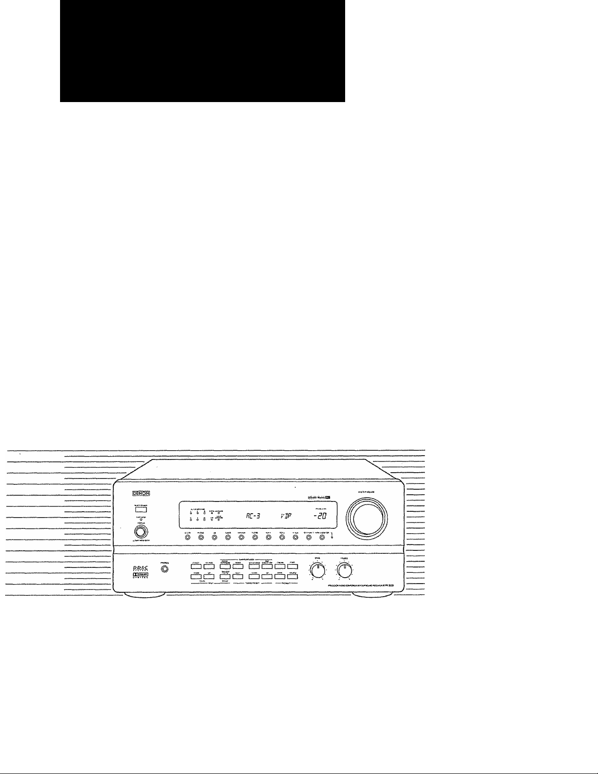
We greatly appreciate your purchase of the AVR-3600.
To be sure you take maximum advantage of ail the features the AVR-3600 has to offer, read these instructions care>
fully and use the set properly. Be sure to keep this manual for future reference should any questions or problems
arise.
'SERIAL NO.
PLEASE RECORD UNIT SERIAL NUMBER ATTACHED TO THE REAR OF THE
CABINET FOR FUTURE REFERENCE"
Page 2
SAFETY FRECAÜTIOIMS
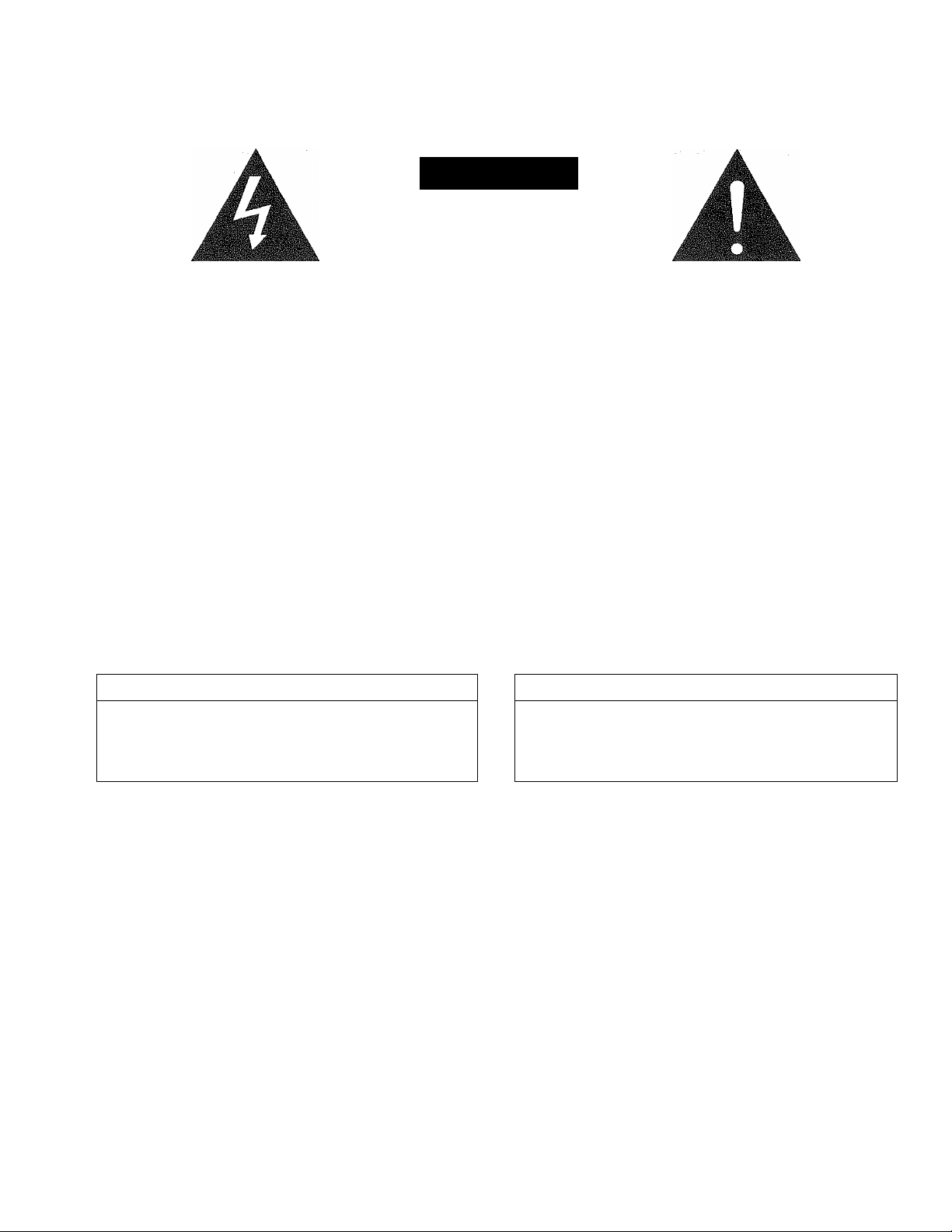
The lightning flash with arrowhead symbol, within an equilateral triangle, is in
tended to alert the user to the presence of uninsulated "dangerous voltage"
within the product's enclosure that may be of sufficient magnitude to constitute
a risk of electric shock to persons.
The exclamation point within an equilateral triangle is intended to alert the user
to the presence of important operating and maintenance (servicing) instructions
A
in the literature accompanying the appliance.
ÍÁIÍTI0N
BISK OF ELECTBiC SHOCK
DO WOT OFEW
CAUTION: TO REDUCE THE RISK OF ELECTRIC
SHOCK DO NOT REMOVE COVER (OR BACK). NO
USER SERVICEABLE FARTS INSIDE. REFER SERVIC
ING TO QUALIFIED SERVICE PERSONNEL.
WARNING: TO REDUCE THE RISK OF FIRE OR ELECTRIC SHOCK, DO NOT EXPOSE
THIS APFLiANCE TO RAIN OR MOISTURE.
CAUTION ATTENTION
TO PREVENT ELECTRIC SHOCK DO NOTUSE THIS {POLARIZED) PLUG
WITH AN EXTENSION CORD, RECEPTACLE OR OTHER OUTLET UN
LESS THE BLADES CAN BE FULLY INSERTED TO PREVENT BLADE EX
POSURE.
POUR PREVENIR LES CHOCS ELECTRIQUES NE PAS UTILISER CEHE FI
CHE POLARISEE AVEC UN PROLONGATEUR UNE PRISE DE COURANT
OU UNE AUTRE SORTIE DE COURANT, SAUF Si LES LAMES PEUVENT
ETRE INSEREES A FOND SANS EN LAISSER AUCUNE PARTIE A DECOU
VERT.
Page 3
SAFETY INSTRUCTIONS
1. Read Instructions - All the safety and operating instruc
tions should be read before the appliance is operated.
2. Retain Instructions - The safety and operating instruc
tions should be retained for future reference.
3. Heed Warnings - All warnings on the appliance and in the
operating instructions should be adhered to,
4. Follow Instructions - All operating and use instructions
should be followed.
5. Water and Moisture - The appliance should not be used
near water ~ for example, near a bathtub, washbowl,
kitchen sink, laundry tub, in a wet basement, or near a
swimming pool, and the tike.
6. Carts and Stands “ The appliance should be used only
with a cart or stand that is recommended by the
manufacturer.
6A. An appliance and cart
combination should be
moved with care.
Quick stops, exces
sive force, and uneven
surfaces may cause
the appliance and cart
combination to overturn,
7. Wall or Ceiling Mounting - The appliance should be
mounted to a wall or ceiling only as recommended by the
manufacturer.
8. Ventilation - The appliance should be situated so that its
location or position does not interfere with its proper ven
tilation, For example, the appliance should not be si
tuated on a bed, sofa, rug, or similar surface that may
block the ventilation openings; or, placed in a built-in
installation, such as a bookcase or cabinet that may im
pede the flow of air through the ventilation openings.
9. Heat - The appliance should be situated away from heat
sources such as radiators, heat registers, stoves, or other
appliances (including amplifiers) that produce heat.
10. Power Sources -- The appliance should be connected to
a power supply only of the type described in the operat
ing instructions or as marked on the appliance.
11. Grounding or Polarization - Precautions should be taken
so that the grounding or polarization means of an ap
pliance is not defeated.
12. Power-Cord Protection - Power-supply cords should be
routed so that they are not likely to be walked on or
pinched by items placed upon or against them, paying
particular attention to cords at plugs, convenience recep
tacles, and the point where they exit from the appliance.
14. Cleaning - The appliance should be cleaned only as rec
ommended by the manufacturer,
15. Power Lines - An outdoor antenna should be located
away from power lines,
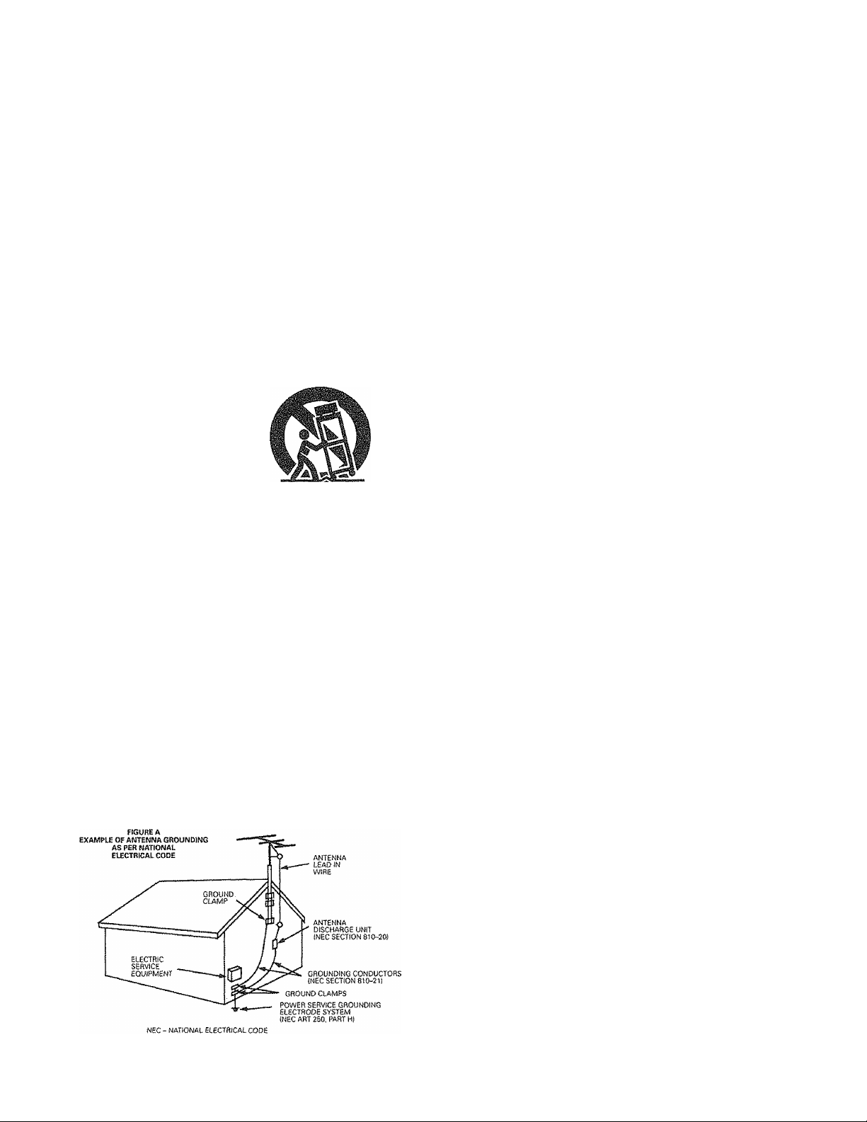
16. Outdoor Antenna Grounding - If an outside antenna is
connected to the receiver, be sure the antenna system
is grounded so as to provide some protection against
voltage surges and built-up static charges. Article 810 of
the National Electrical Code, ANSI/NFPA70, provides in
formation with regard to proper grounding of the mast
and supporting structure, grounding of the lead-in wire
to an antenna-discharge unit, size of grounding conduc
tors,. location of antenna-discharge unit, connection to
grounding electrodes, and requirements for the ground
ing electrode. See Figure A,
17. Nonuse Periods - The power cord of the appliance should
be unplugged from the outlet when left unused fora long
period of time,
18. Object and Liquid Entry - Care should be taken so that ob
jects do not fall and liquids are not spilled into the enclo
sure through openings.
19. Damage Requiring Service - The appliance should be
serviced by qualified service personnel when;
A. The power-supply cord or the plug has been dam
aged; or
B. Objects have fallen, or liquid has been spilled into the
appliance; or
C. The appliance has been exposed to rain; or
D. The appliance does not appear to operate normally or
exhibits a marked change in performance; or
E. The appliance has been dropped, or the enclosure
damaged,
20. Servicing - The user should not attempt to service the ap
pliance beyond that described in the operating instruc
tions. All other servicing should be referred to qualified
service personnel.
Page 4
T
Note on Use
Before Using ..............................................
2.
3 Cautions on Installation
4
Cautions on Handling
5 Connections
6 System Setup ..,;
Remote Control Unit ..................................
JL
..............................................
.............................
................................
.............................................
....................................
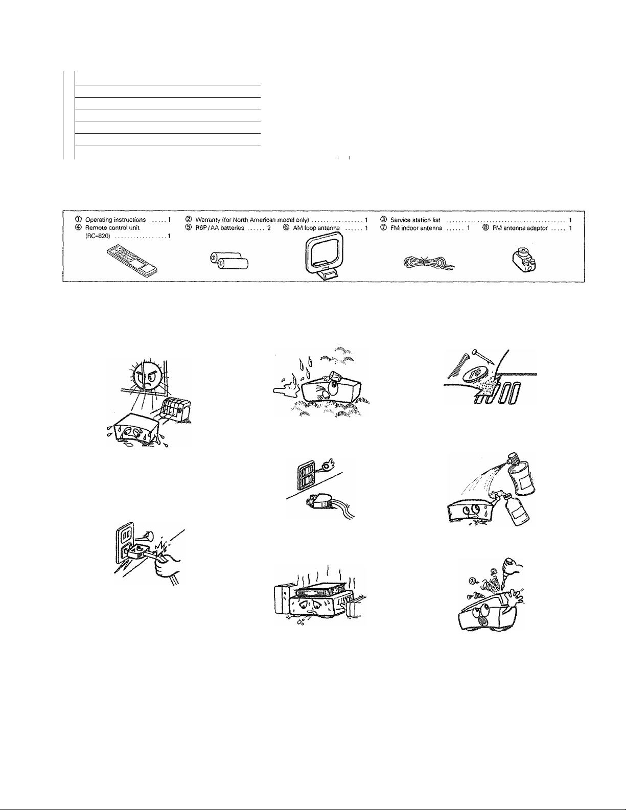
ACCESSORIES
[Tj NOTE ON USE
TABLE OF CONTEIMTS
...................................
...................................
...................................
...................................
...........................
.......................... n-17
.........................
Check that the foliowing parts are included in addition to the main unit:
4
5
5
5 11
6-10
18-22
Operations
Using the Surround Function
1.
Listening to the Radio ............................................................32—34
10
Last Function Memory
Initialization of the Microprocessor ............................................... 34
11
Troubleshooting ............................................................................ 35
13
14
Specifications
.............................................................................
................................................................
.........................................................................
................................................
22—25
26—32
34
bottom
® Avoid high temperatures
Allow for sufficient heat dispersion
when installed on a rack.
Handle the power cord carefully,
Hold the plug when unplugging the
cord.
® Keep the set free from moisture,
water, and dust.
® Unplug the power cord when not
using the set for long periods of
time.
*(For sets with ventilation holes)
® Do not obstruct the ventilation
holes.
X
® Do not let foreign objects in the set.
® Do not let insecticides, benzene, and
thinner come in contact with the set.
® Never disassemble or modify the set
in any way.
Page 5
2 BEFORE USING
Pay attention to the foMowing before using this unit:
9 Moving the set
To prevent short circuits or damaged wires in the connection cords,
always unplug the power cord and disconnect the connection
cords between a!i other audio components when moving the set.
« Before turning the power switch on
Check once again that all connections are proper and that there
are not problems with the connection cords. Always set the
power switch to the standby position before connecting and
disconnecting connection cords.
3 CAUTIONS ON INSTALLATION
Noise or disturbance of the picture may be generated if this unit or any
other electronic equipment using microprocessors is used near a tuner
or TV,
If this happens, take the following steps:
® install this unit as far as possible from the tuner or TV.
® Set the antenna wires from the tuner or TV away from this unit's
power cord and input/output connection cords.
® Noise or disturbance tends to occur particularly when using indoor
antennas or 300 Q/ohms feeder wires. We recommend using
outdoor antennas and 75 C2/ohms coaxial cables.
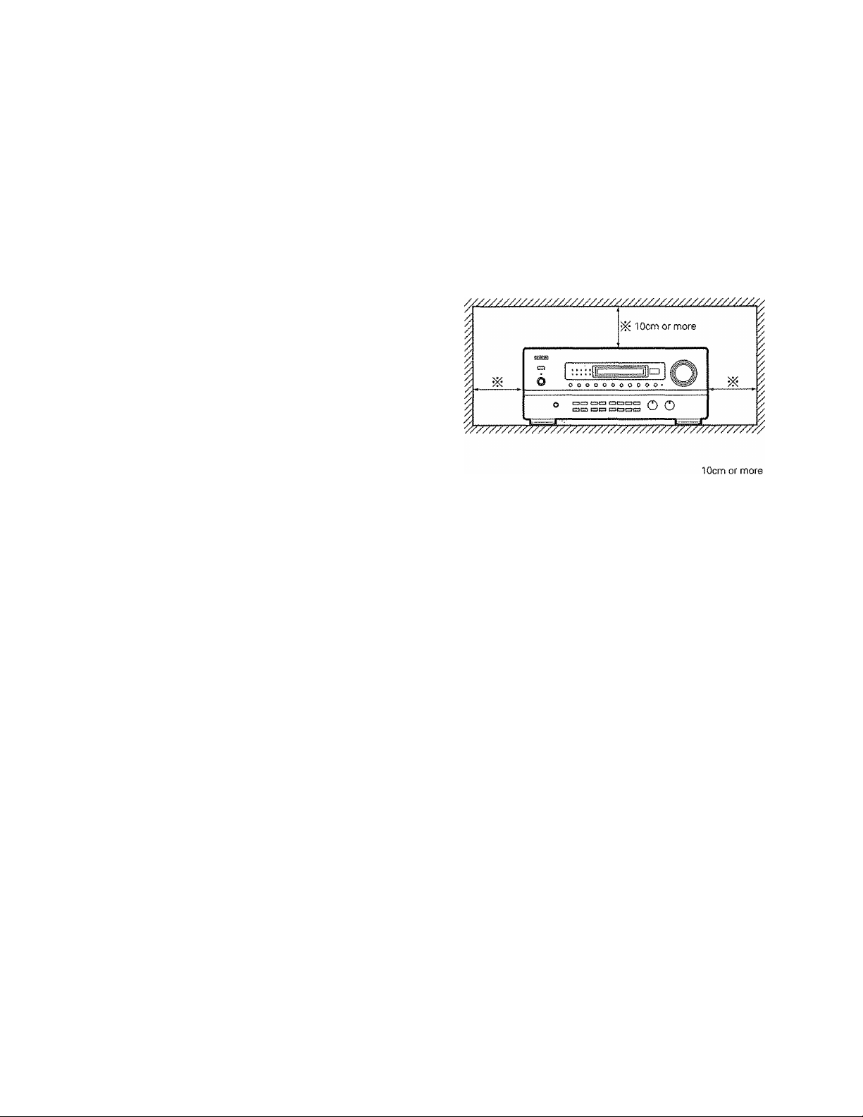
For heat dispersal, leave at least 10 cm of space between the top, back and sides of this unit and the wall or other components.
Store this instructions in a safe place.
After reading, store this instructions along with the warranty in a
safe place. Also fill in the items on the back page for your conve
nience.
Note that the illustrations in this instructions may differ from the actual set for explanation purposes.
I
ÿ Wall
0 CAUTIONS ON HANDLING
® Switching the input function when input jacks are not con
nected
A clicking noise may be produced if the input function is switched
when nothing is connected to the input jacks. If this happens, either
turn down the MASTER VOLUME control or connect components
to the input jacks.
Muting of PRE OUT jacks
The PRE OUT jacks include a muting circuit. Because of this, the
output signals are greatly reduced for several seconds after the
power switch is turned on or input function, surround mode or any
other set-up is changed. If the volume is turned up during this time,
the output will be very high after the muting circuit stops function
ing, Always wait until the muting circuit turns off before adjusting
the volume.
I
® Whenever the power switch is tn the OFF state, the apparatus
is stilt connected on AC tine voltage.
Please be sure to unplug the cord when you leave home for, say,
a vacation.
Page 6
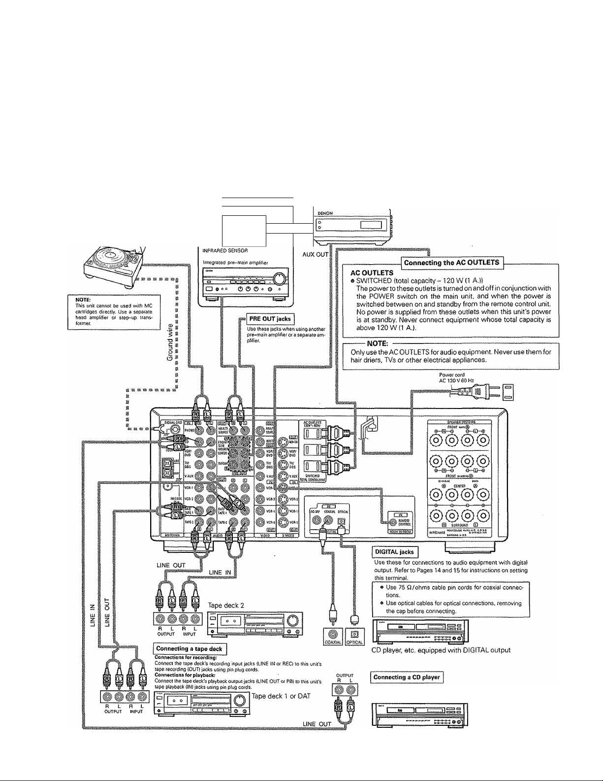
5 COfSINECTIOIMS
® Do not plug in the power cord until all connections have been
completed.
® Be sure to connect the left and right channels properly (left with
left, right with right).
® Insert the plugs securely. Incomplete connections will result in
the generation of noise,
® Use the AC OUTLETS for audio equipment only. Do not use
them for hair driers, etc,
5-1 Connecting the audio components
Turntable |MM cartridge)
f Another room I---------^
DEMON
N dI
OUTPUT
S)
0
INPUT!
m]
! 1
0“
Note that binding pin plug cords together with power cords or
placing them near a power transformer will result In generating
hum or other noise.
Noise or humming may be generated if a connected audio
equipment is used independently without turning the
power of this unit on. If this happens, turn on the power
of the this unit.
RC-656
!№RAR£D
RETRANSMITTER
Connect ttie CD player's analog output jacks {ANALOG OUT
PUT) to this unit's CD jacks using pin plug cords.
CD player
Page 7
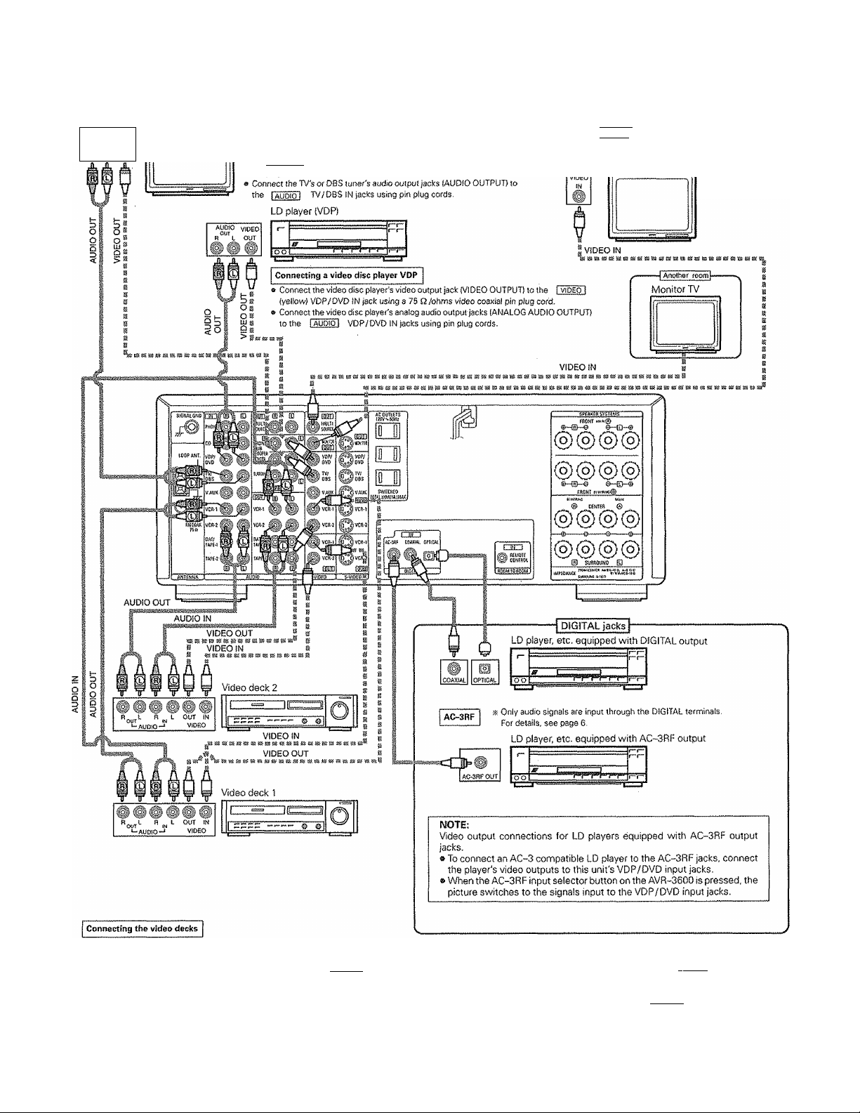
5-2 Connecting the video equipments
To connect the video signal, connect using a 75 Q/ohms video signal cable cord. Using an improper cable can result in a drop in sound quality.
AUDIO
VIDEO
OUT
)®
TV or DBS tuner
Connecting a TV / DBS tuner
TV/DSS
e Connect the TV's or DBS tuner's video output jack (VIDEO OUTPUT) to
the I VIDE o' I (yeitow) TV/DSS !W jack using a 75 Q/ohms video coaxial
pin plug cord.
MONITOR OUT
* Connect the TV's video input jack (VIDEO INPUT) to
the i vìdeo I MONITOR OUT jack using a 75
Q /ohms video coaxial pin
Monitor TV
plug
cord,
a There are two sets of video deck (VCR) jacks, so two video decks cart be connected for simultaneous recording or video copying.
Video input / output connections:
e Connect the video deck's video output jack (VIDEO OUT) to the 1 vioÉb I
(yellow) VCR-1 OUT jack using 75 Q /ohms video coaxial pin plug cords.
Connecting the audio output jacks
» Contiect the video deck's audio output jacks (AUDIO OUT) to the I audio 1
OUT jacks using pin plug cords,
K Connect the second video deck to the VCR-2 jacks in the same way,
(yellow) VCR-1 IN jack, arid the video deck's video input jack (VIDEO
VCR-1 IN jacks, and the video deck's audio input jacks (AUDIO IN) to the l AUDio I VCR-1
IN)
to the I video j
Page 8
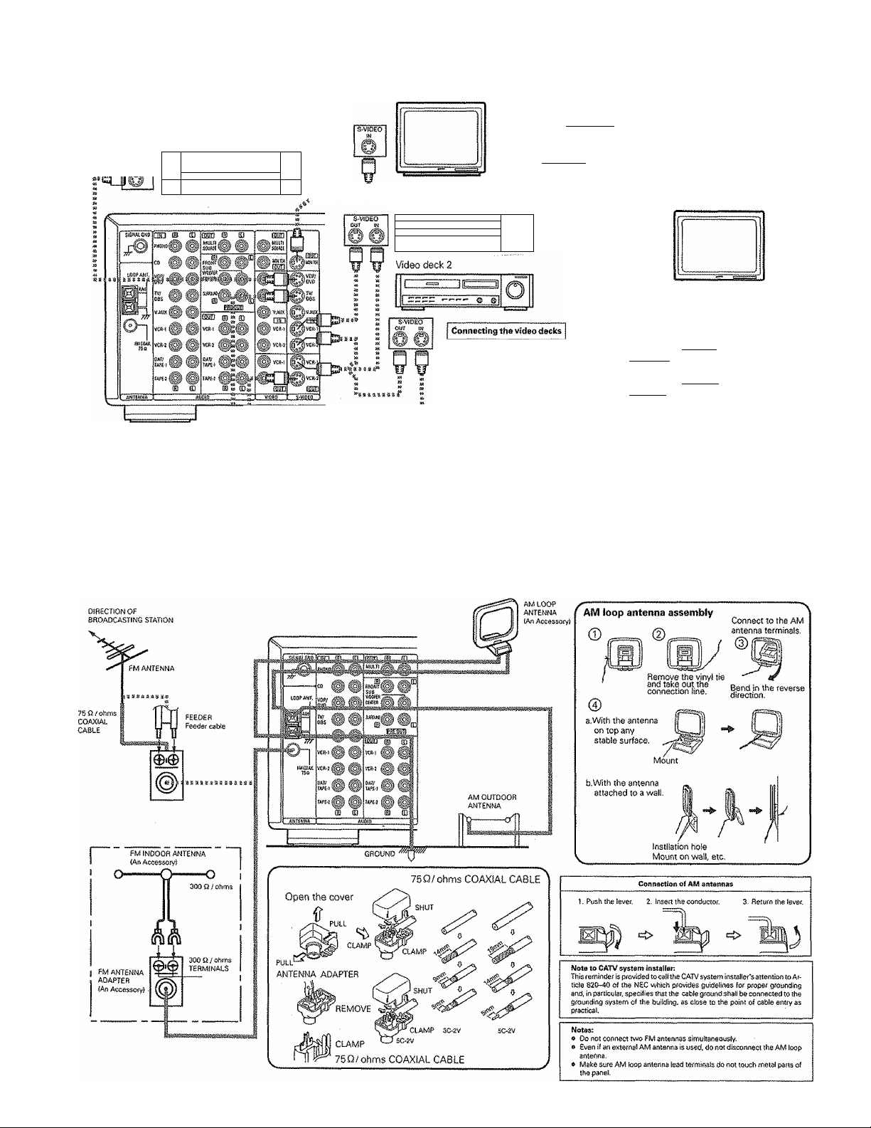
5-3 Connecting the S-vIdeo terminals
LD player, (VDP)
r"
r“r“
f~i—
Monitor TV
Connecting a TV / DBS tuner
TV/DBS
e Connect ttie TV's or DBS tuner's S video output jack (S-VIDEO OUTPUTJ
to the I S-VIDEO I TV/D8S IN jack using an S jack connection cord,
MONITOR OUT
« Connect the TV's of DBS tuner's S video input {S-VIDEO INPUT} to the
I s-ViOEQl MONITOR OUT jack using a S jack connection cord.
■osiiìicsesiijaeia
Video deck 1
1 C-2-,
...............................
L..E.EEc:,
.................
.....
ÎÏ
O
0 Connect the video deck’s S output jack (S-OUT) to the I s-^dedl VCR-1 IN jack and
the video deck's S input jack iS-IN) to the i s-viDEOi VCR-1 OUT jack using S jack
connection cords,
» Connect the video deck's S output jack (S-OUT) to the fs-viDEdi VCR-2 IN jack and
the video deck's S input jack (S-IN) to the is-vidEOi VCR-2 OUT jack using S jack
connection cords,
TV or DBS toner
A note on the S input jacks
The input selectors for the S inputs and pin jack inputs work in conjunction with each other.
Precaution when using S~jacks
This unit's S-jacks (input and output} and video pin jacks (input and output) have independent circuit structures, so that video signals input
from the S~jacks are only output fronh the S-jack outputs and video signals input from the pin jacks are only output from the pin jack outputs.
When connecting this unit with equipment that is equipped with S-jacks, keep the above point in mind and make connections according to the
equipment's instruction manuals.
5-4 Connecting the antenna terminals
8
Page 9
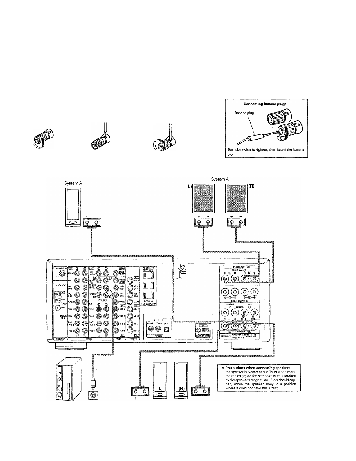
5-5 Speaker system connections
» Connect the speaker terminals with the speakers making sore that like polari
ties are matched {© with ©, © with © ). Mismatching of polarities wiil result
in weak central sound, unclear orientation of the various instruments, and the
sense of direction of the stereo being impaired.
» When making connections, take care that none of the individual conductors
of the speaker cord come in contact with adjacent terminals, with other
speaker cord conductors, or with the rear panel.
Connecting the speaker terminéis
Speaker Impedance
» When speaker systems A and 8 are use separately, speakers with an imped
ance of from 8 to 16 Q/ohms cart be connected tor use as front and center
speakers.
e Be careful when using two pairs of front or center speakers {A -i- 3} at the
same time, since use of speakers with an impedance of less than l6i3/ohms
will lead to damage,
® Speakers with an impedance of 8 to 16 £2 / ohms can be connected for use as
surround speakers.
o The protection circuit may operate or damage may occur when speakers with
an impedance outside of the above range are used.
1. Loosen by turning
counterclockwise,
CENTER SPEAKER SYSTEM
2, Insert the cord. 3. Tighten by turning
clockwise.
FRONT SPEAKER SYSTEMS
Connection jack for sub
woofer with bullt-ir) ampli
fier {super woofer), etc,
SURROUND SPEAKER SYSTEMS
Page 10
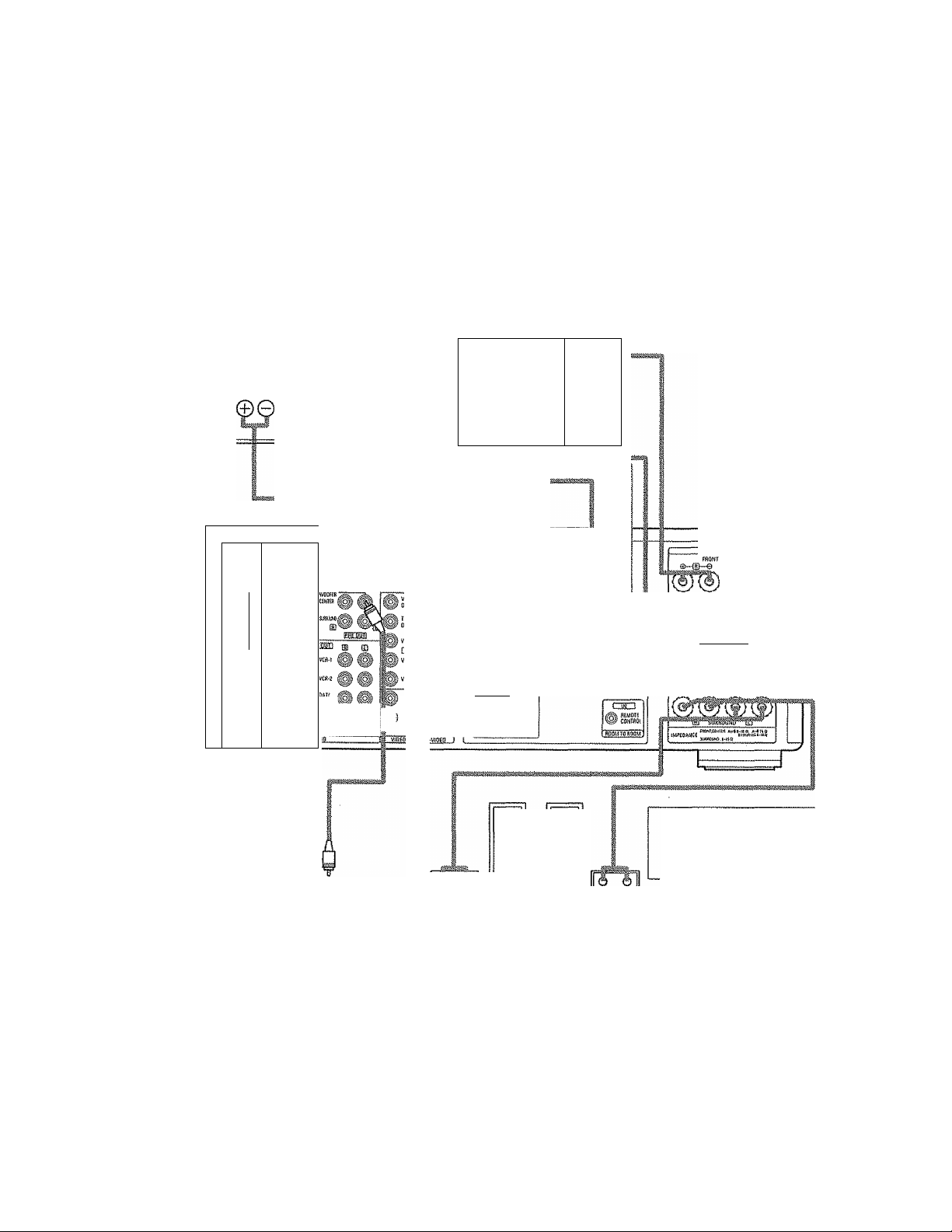
& About bt-wiring
Sf your speakers bave bi-wiring terminais, you can achieve higher quality sound by adding cords and using bi-wiring, as shown on the
diagram below.
® By connecting speaker systems to both the speaker A and B terminals, you can play the same music source simultaneously in different
rooms. (Use speakers with impedances of 16 £3/ohms.)
® By adding an integrated amplifier, you can use the multi-source terminals to play the other music source simultaneously in different rooms.
(See page 26.)
8i“Wiring procedure
CENTER SPEAKER SYSTEM
(S-
\
. .. . ..
CSD (H CD
iNT,
r.
«
H"
Hr
i
TO! ^ ^
o-
fwceAX.
_
'
i'.-
©
SPEAKER SYSTEM (81WiRiNG)
When bi~wiring with bt~
wireabîe speakers, con
nect the mid and high
range terminals to SYS
TEM (A) lor SYSTEM (B)i,
the tow range terminals
to SYSTEM (B) (or SYS
TEM (Aj).
m CD
ff P VCft J
FRONT SPEAKER SYSTEMS
(L)/
HIGH HIGH Ji
LOW 1
«li
.asm
_f i'iwllf
'AC'Jffi CÛJUÜAt 0?IfCAt
OSiD
(R)
I
LOW
mm>
mm i.'naM®
10
Connection ¡ack for subwoofer with built-in ampli
fier (super woofer), etc.
(U
ero
SURROUND SPEAKER SYSTEMS
ÌR)
» Precautions when connecting speakers
If a speaker is placed near a TV or video moni
tor, the colors on the screen may be disturbed
by the speaker's magnetism. If this should itappen, move the speaker away to a position
where it does not have this effect.
Page 11
d] SYSTEM SETUP
After connections with other components have been made, make the various settings on the monitor using this unit's on-screen display. These settings must be made in order to complete the AV system in your listening room.
Make the seven settings described below.
(D speaker Configuration
(D Delay Time
® Channel Level
@ Digital Input (only when an AV component is connected to the digital input jacks)
(D AC-3
© Auto Tuner Preset
® On Screen Display
NOTES:
® The output from the S MONITOR OUT terminal has priority for the on screen display. If you want to always output the on screen display
signals to the video output do not connect a cable to the S MONITOR OUT terminal,
® The on screen display is not displayed for the MULTI SOURCE MONITOR OUT terminal,
e This model's on screen function is designed for high resolution monitor displays.
Small characters may be difficult to read on small displays or low resolution TVs.
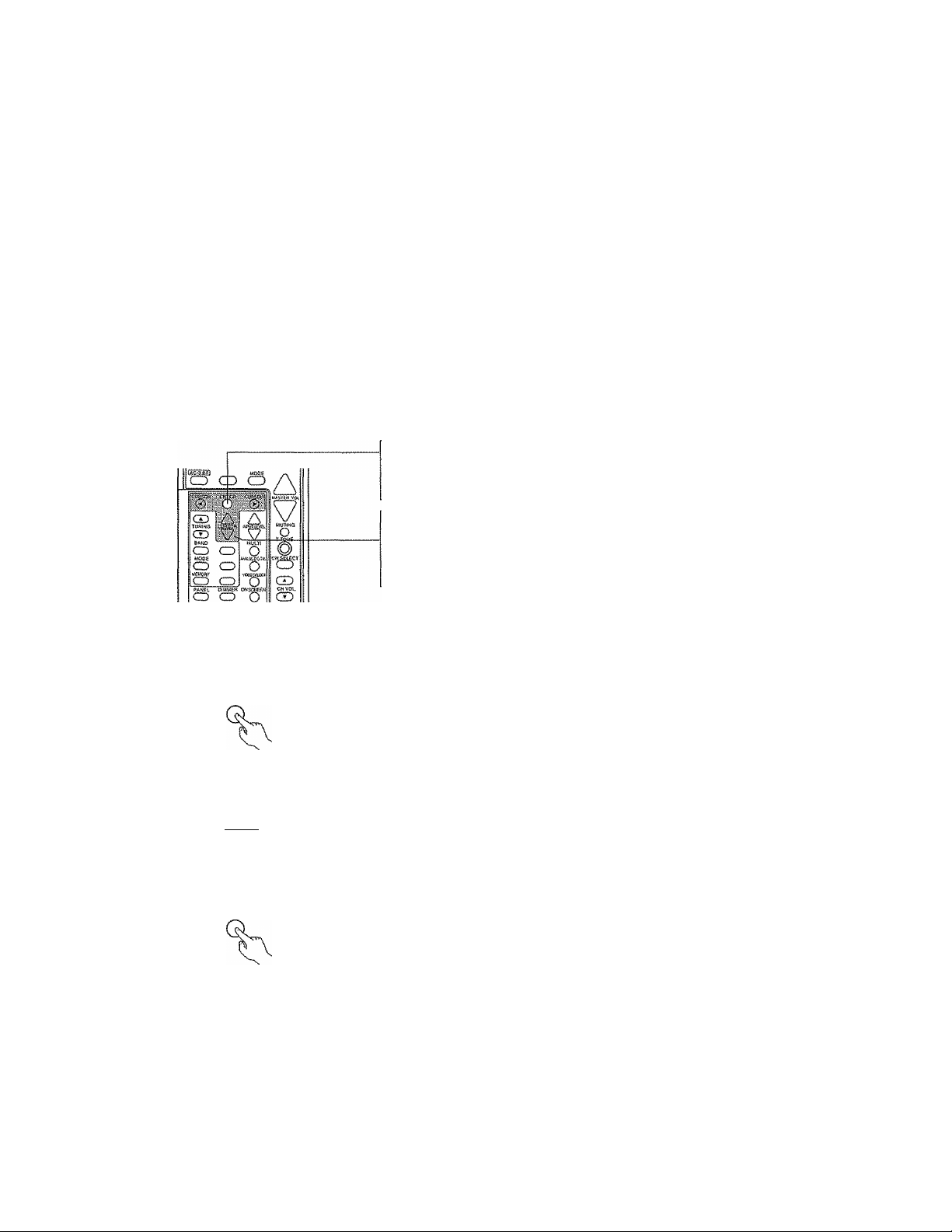
Use the following buttons on the remote control unit to make the settings:
"ENTER" button
Press this to switch the display on the screen.
Also use this button to complete the setting on the screen.
'CURSOR" buttons
@ and ® : Use these to move the cursors {^ and ^) to the left and right on the
A and V : Use these to move the cursors (A Qtid W) up and down on the screen.
screen.
6-1 Before setting up the system
1. Turn on the power and press the ENTER button.
The "Menu" screen (screen 1) appears on the monitor.
2, Use the CURSOR buttons to specify "System Setup'
A
cuRsoa^
3. Press the ENTER button to switch the screen.
The "System Setup Menu" screen (screen 2} appears on the monitor.
Menu
crSystem Setup
Surround Parameters
Tuner Preset Stations
Menu Off
( screen 1 }
System Setup Menu
□"Speaker Configuration
’’'Delay Time
Channel Level
Digital Inputs
AC-3
Auto Tuner Presets
On Screen Display
Setup Menu Off
i screen 2 )
11
Page 12

6-2 Setting the speaker configuration
1. Use the CURSOR buttons to specify "Speaker Configuration" from the "System Setup
Menu" screen (screen 2).
Speaker Configuration
___
gFront Sp.
CU^R ^
Q
О
2. Press the ENTER button.
(screen 3 )
The "Speaker Configuration Menu" screen (screen 3} appears on the monitor,
3. Use the CURSOR buttons and select the different types of speakers connected and
their size parameters.
To select the speakers:
Л
CURSOR Cv
® Parameters
Large
.............................
Small
.............................
None .............................. Select this when no speakers are installed,
Yes/No............................ Select "Yes" when surround speakers and a subwoofer are installed, "No" when they are not installed,
Select this when using speakers that can fully reproduce low sounds of below 80 Hz,
Select this when using speakers that cannot reproduce low sounds of below 80 Hz with sufficient volume.
When this setting is selected, low frequencies of below 80 Hz are assigned to the subwoofer.
To select the parameters:
CURSOR CURSOR
The selected parameters are highlighted.
Center Sp.
Surround Sp.
И
Subwoofer
4. After the above selections are completed, press the ENTER button again.
The "System Setup Menu" screen reappears.
6-3 Setting the delay time
Input the listening position and the distance of the different speakers.
1. Use the CURSOR buttons to specify "Delay Time" from the "System Setup Menu"
screen (screen 4).
Д
CURSOR
2. Press the ENTER button.
ENTER
The "Delay Time" screen (screen 5) appears on the monitor.
3. Use the CURSOR buttons to specify the unit of distance,
CURSOR CURSOR
System Setup Menu
^Speaker Configuration
E3“De!ay Time
^Channel Level
Digital Inputs
AC-3
Auto Tuner Presets
On Screen Display
Setup Menu Off
{screen 4)
Delay Time
Set The Distance To
Each Speakers
Do You Prefer
In Meters ? / in Feet?
□“Meters
< • >
Feet
NOTE: The settings are reset to their initial values when switching between meters and
feet.
12
(screen 5 )
Page 13

4. Use the CURSOR buttons to input the listening position and the distance of the differ
ent speakers, {screen 6-A)
FL
FR
To select the speakers:
CU^R fv
^ Select "Default" to return to the initial settings,
5, After the above selections are completed, press the ENTER button again.
The "System Setup Menu" screen reappears.
This procedure automatically sets the optimum surround delay time for the listening
room.
s; If you set an invalid distance, a CAUTION notice, such as screen 6~B will appear. In this
case, please relocate the blinking speaker(s} so that its distance is no larger than the
value shown in highlighted line. Then press the ENTER button again.
^ Set in such a way that the distance to the center speaker is the same as or up to 5 feet
0.5 meters) shorter than the distance to the front left and front right speakers and the
subwoofer.
To select the distance:
CURSOR CURSOR
0^0
Sub
-woofer
Delay
Q
0
V
Delay Time
BETOGATE'B
-------------
Time
crFL, FR
T&Siibwooier
Center 12 ft
SL&SR 10 ft
Default
_______________
( screen 6-A )
GAUTIOr^!
FU FR
&Sybwoofer
^2ft^
^ Set in such a way that the distance to the surround left and right speakers is the same
as or up to 15 feet (4.5 meters) shorter than the distance to the front left and front right
speakers and the subwoofer.
6-4 Setting the channel level
Use test tones to adjust the volume of the different speakers.
1. Use the CURSOR buttons to specify "Channel Level" from the "System Setup Menu"
screen, (screen 7)
A
CURSOR fv
2. Press the ENTER button.
The "Channel Level" screen (screen 8) appears on the monitor,
3, Use the CURSOR buttons to select "TestTone Mode", then select "Auto" or "Manu
al".
A
CURSOR Cv
CURSOR CURSOR
© ^0
{ screen 6~B )
System Setup Menu
Speaker Configuration
ADeiay Time
crChannei Level
’^Digital Inputs
AC-3
Auto Tuner Presets
On Screen Display
Setup Menu Off
( screen 7 )
Channel Level
crLevei Clear ,
____
Test Tone Mode
,
^ ► I Manual
4, Use the CURSOR buttons to select "Test Tone Start", then select "Yes".
CURSOR
CURSORK
vK
Test Tone Start
screen 8 )
13
Page 14

5. a. If the "Auto''mode is selected:
'The test ions is
emitted from
the speaker
whose indicator
is highlighted.
A
CURSOR Pv
b. if the "Manual" mode is selected:
Use the cursor buttons to select the speakers from which to
emit the test tones and adjust the volume, (screen 10)
To adjust the volume:
C№^R Pv
The level of each channel should be adjusted to 75 dB (C'-weighted, slow meter mode) on a sound level meter at the listening position.
If a sound level meter is not available adjust the channels by ear so the sound levels are the same. Because adjusting the subwoofer level test
tone by ear is difficult, use a well known music selection and adjust for natural balance.
NOTE: When adjusting the level of an active subwoofer system, you may also need to adjust the subwoofer's own volume control.
6. After the above settings are completed, press the ENTER button again.
The "System Setup Menu" screen (screen 2) reappears.
To cancel the settings, select "Level Clear" and "Yes" on the "Channel Level" screen, then make the settings again.
NOTES; ® The output channel levels for all the surround modes are set to the same conditions when the channel level setting on the system
setup menu is conducted,
® When the level clear operation is performed, all channel levels for all modes are set to 0 dB.
To select the speaker;
CURSOR CURSOR
© ^
( screen 9 )
,The test tone is
emitted from
the speaker
whose indicator
is highlighted.
6-5 Digital input setup
Input the types of components connected to the digital input terminals,
1, Use the CURSOR buttons to specify "Digital Inputs" from the "System Setup Menu"
screen, (screen 11)
A
CURSOR Cv
2. Press the ENTER button.
The "Digital input Setup" screen appears, (screen 12)
3. Use the cursor buttons to input the types of components connected to the digital input
terminals.
To select the input terminal:
To select the type of component;
CURSOR CURSOR
ik Select "OFF" if nothing is connected.
14
System Setup Menu
Speaker Configuration
Delay Time
¿Channel Level
crDigital inputs
'^AC-3
Auto Tuner Presets
On Screen Display
Setup Menu Off
( screen 11 )
Digital Inputs Setup
¡tI COAXIAL I :
TldPTiCALl :
Default
¡VDPA)VPÌÌTVCTs1Ìv!auxT
^ |TAPe-i
[VCR-11 jvCR-2ÌÌ OFF 1.
( screen 12 )
Page 15

Select "Default" to return to the initial settings.
The initial settings are set as shown on Table 6”5,
4. After the above settings are completed, press the ENTER button again.
The "System Setup Menu" screen reappears.
6-6 Dolby Digital AC-3
When playing Dolby Digital AC~3 sources, the input level is corrected automatically.
Set the dialog normalization function,
1. Use the CURSOR buttons to specify "AC~3" from the "System Setup Menu" screen.
(Screen 13}
A
CUaSQR^
2. Press the ENTER button.
The "AC”3" screen appears. (Screen 14)
3. Use the CURSOR buttons to select "ON" or "OPE".
COAXIAL
OPTICAL
Table 6”5 Initial Settings
CD
VDP/DVD
System Setup Menu
Speaker Configuration
Delay Time
Channel Level
ADigita! Inputs
s-AC-S
^Auto Tuner Presets
On Screen Display
Setup Menu Off
(screen 13)
CURSOR CURSOR
When playing Dolby Digital AC~3 sources
MOTE: If dialog normalization is set to "OFF", it may not be possible to set the master volume to greater than 5 dB, depending on the number
of speakers and the output channel level setting.
15
Page 16

6-7 Auto tuner presets
Use this to automaticalSy search for FM broadcasts and store up to 40 stations at preset
channels A1 to 8, B1 to 8, C1 to 8, D1 to 8 and El to 8.
NOTE:
if an FM station cannot be preset automatically due to poor reception, use the "Manual
tuning" operation to tune in the station, then preset it using the manual "Preset memory"
operation.
1. Use the CURSOR buttons to specify "Auto Tuner Preset" from the "System Setup
Menu" screen, (screen 15)
2. Press the ENTER button.
The "Auto Preset Memory" screen appears, (screen 16)
3, Use the CURSOR buttons to select "Yes".
CURSOR
System Setup Menu
Speaker Configuration
Delay Time
Channel Level
Digital Inputs
aAC-3
crAuto Tuner Presets
^On Screen Display
Setup Menu Off
( screen 15 )
Auto Preset Memory
Auto Tuning &
Preset Station Memory
Storing Preset Memory
□“Start
i
( screen 16 )
"Search" flashes on the screen and searching begins.
"Complete" appears once searching is completed.
The display automatically switches to screen 17,
4, Check the broadcast stations stored in the memory.
Press the ENTER button, (screen 17)
The monitor switches to.the "Menu" screen, (screen 18}
5, Use the CURSOR buttons to specify "Tuner Preset Stations".
A
CURSOR
6. Press the ENTER button.
The display switches to screen 19 and the frequency of the preset station is displayed.
When the CURSOR button is pressed, the displayed page changes and the frequencies
of other preset stations can be checked.
CURSOR
After checking, press the ENTER button again.
ENTER
System Setup Menu
Speaker Configuration
Delay Time
Channel Level
Digital Inputs
AC-3
Auto Tuner Presets
^On Screen Display
□“Setup Menu Off
{screen 17 }
Menu
System Setup
A Surround Parameters
i^Tuner Preset Stations
Menu Off
( screen 18 )
Tuner Preset Stations
A1fm
A2fm
A A3fi^
Cf
VA5FM 97.90Mhz
[Shift I»'
87.50MHz
88.10Mhi
89.30Mhz
Ì'SGMhz
A6fm104.10Mhz
A7fm106.50Mhz
A8fm 107.90MHz
16
{screen 19}
Page 17

6-8 On Screen Display
"ON" or "OFF" can be selected for functions other than the ones on the nnenu screen.
1. Use the CURSOR buttons to specify "On Screen Display" from the "System Setup
Menu" screen, (screen 20)
CU^OR
2. Press the ENTER button.
The "On Screen Display" screen (screen 21) appears on the monitor.
3. Use the CURSOR buttons to select "ON" or "OFF",
CURSOR CURSOR
fK This completes the system setup operations. Once the system is set up, there is no
need to make the settings again unless other components or speakers are connected
or the speaker layout is changed.
6“9 Operation after completing system setup
1. Use the CURSOR buttons to specify "Setup Menu Off" from the "System Setup
Menu" screen, (screen 22)
System Setup Menu
Speaker Configuration
Delay Time
Channel Level
Digital Inputs
AC-3
^Auto Tuner Presets
iTOn Screen Display
^Setup Menu
Of f
{ screen 20 )
i screen 21 )
System Setup Menu
2. Press the enter button twice to turn off the on screen display,
EMTSR
SYSTEM SETUP DEFAULT VALUE
® SPEAKER CONFIGURATION
© DELAY TIME
©CHANNEL LEVEL
© DIGITAL INPUTS
©AC-3
©AUTO TUNER PRESET
A1~A8
BÌ-B8
C1~C8 90,1 MHz
D1-D8 I 90,1 MHz
E1~E8 90,1 MHz
©ON SCREEN DISPLY
FRONT Lch,
OdB OdB OdB
87.5/89,1/98.1/107.9/90,1/90.1/90.1/90,1 MHz
520/600/1000/1400/1500/1710 kHz/90.1/90,1 MHz
FRONT L Si Rch.
SMALL
FRONT L& Rch.
12 ft. (3,6 m)
FRONT Rch.
Speaker Configuration
Delay Time
Channel Level
Digital Inputs
AC-3
Auto Tuner Presets
AOn Screen Display
u’Setup Menu Off
CENTER ch.
SMALL
CENTER ch.
12 ft. (3,6 m)
CENTER ch. SURROUND Lch.
OdB OdB
COAXIAL: CD OPTICAL; VDP/DVD
DIALOG NORMALIZATION: ON
ON
SURROUND L& Rch,
SURROUND L& Rch,
{screen 22 )
YES
10 ft, (3.0 m)
SURROUND Rch. SUBWOOFER
SUBWOOFER
YES
SUB WOOFER
12 ft. (3.6 m)
OdB
Playback with the above setting is possible upon shipment from the factory and after initializing (refer to page 34).
17
Page 18

0 REMOTE CONTROL UNIT
Following the procedure outlined below, insert the batteries before using the remote control unît
M Range of operation of the remote control unit
Point the remote control unit at the remote control sensor as shown on
the diagram at the left.
NOTES:
® The remote control unit can be used from a straight distance of
approximately 7 meters/20 feet, but this distance will shorten or operation will become difficult if there are obstacles between the re
mote control unit and the remote control sensor, if the remote con
trol sensor is exposed to direct sunlight or other strong light, or if op
erated from an angle,
® Neon signs or other devices emitting puise-type noise nearby may
result in malfunction, so keep the set as far away from such devices
as possible.
Inserting the batteries
NOTES:
» Use only AA, R6P, UM-3 batteries for replacement.
• Be sure the polarities are correct, (See the illustration inside the bat
tery compartment,)
® Remove the batteries if the remote control transmitter wilt not be
used for an extended period of time.
a If batteries teak, dispose of them tmmediaieiy. Avoid touching the
leaked material or letting it come in contact with clothing, etc. Clean
the battery compartment thoroughly before installing new batter
ies,
® Have replacement batteries on hand so that the old batteries can be
replaced as quickly as possible when the time comes.
® The codes that have been learned may be lost if removed batteries
are not replaced within about 5 minutes.
7-1 System code buttons
DENON remote-controllable audio components can be controlled using this unit's remote control unit. Note
that some components, however, cannot be operated with this remote control unit.
1. Set to slide switch to "AUDIO" i"AVR/AVC")
AUDiO
AVR/AVC VIDEO
3. Use the buttons shown below to operate the audio component.
For details, refer to the respective component's manual,
a. For CD players and DATs b. For tape decks (DECK)
ŒD GD CD\ CD
SYSTEhif QaU
V VOLUMSa
la a cdI
m
li
DISC
SKIP+
Manual search (reverse and forward)
Stop
Play
Auto search
Pause
Disc selection
(CD changer only)
2. Set the slide switch to the position for the
component to be operated (CD, DECK or
DAT), CD DECK DAT
VDPVCR TV
7
volume *
) C )^l )
¡""shift ... CHÀNNË1,
B
m : Stop
^ : Forward play
II : Pause
A/8 : A/B deck selection
^ : Reverse play
_____
; Reverse
: Forward
0!$C SKIfi
lo a al
18
DENON teJFgom hc-S201
USei.eAtiN AWIQ.—
..
0-- mn .Sigr
CID CD Cr> O
■ïvCz-rETiJ i'it» 1 '. .
(Dtl
tTvw ri5üF~ OswwEiZr'
I® Jo G3 CD
® ®
GüiTiS! ,y. ^
® ®, (ST
O CT CD
These buttons does not function.
(Some buttons can be used by using the pre
set memory or the learning function,}
-----
3
MOM
Page 19

7“2 Preset memory
DENON and other makes of components can be operated by setting the preset memory for your make of video component. Operation is not pos
sible for some models, however. In this case use the learning function (see page 21) to store the remote control signals.
For instructions on clearing the presettings stored in the preset memory, see page 22,
1, Set the slide switch to "VIDEO",
AUDIO
AVFl/AVC VIDEO
2, Set the slide switch to the component to be
registered (VDP, VCR or TV}.
CO DECK DAT
VDP VCR TV
/ Keep the POWER button pressed in when \
\ performing steps 3 and 4, j
3, Holding in the POWER button, press the but
ton for the corresponding manufacturer in
block A,
(Refer to Table 7-2.)
Flashes
Next, while holding in the POWER button,
press the button for the code in block B. (Re
fer to Table 7-2.) The operation is completed
when the LEARNED/TX LED lights.
5. To continue registering other components,
repeat steps 2 to 4,
The LEARNED/TX LED flashes,
This remote control unit can be used to operate components of other manufacturers without using the learning function by registering the manufactur
er of the component as shown on Table 7-2.
Table 7“2: Combinations of Personal System Codes for Different Manufacturers
'VDP"
A
®
(PHONO)
®{CD)
(4) (TUNER)
® (VDP/DVD)
©(TV/DBS)
(T)(DATAAPE-1)
®(TAPE-2MON)
® (VCR-1)
® (VCR-2)
®(V.AUX)
в
(AC-3RF)
CMSEiyr
(CH SELECT)
DENON A
MITSUBISHI
PANASONIC
SONYA
PIONEER
SANYO
SHARP
—
PHILIPS
RCA
CD
CH vot,
(CH VOL.)
DENON В
—
—
SONY В
—
— —
- —
“
—
“
CH VOL,
CD
(CH VOL.)
DENON C
-
—
—
-
SONYC
-
-
"VCR"
A
Ф
@ (PHONO)
®{CD)
{4) (TUNER)
(VDP/DVD)
(6)(TV/DBS)
(7)(DAT/rAPE-1)
® (TAPE-2MON)
®IVCR~n
(VCR-2)
® (VAUX)
ÍAC-3RF)
CH SELECT
В
(CH SELECT)
HITACHI A HITACHI B HITACHI C
MITSUBISHI A MITSUBISHI B MITSUBISHI c
PANASONIC A PANASONIC B
JVC (VICTORIA
SONYA SONY 8 SONYC
PIONEER
TOSHIBA A TOSHIBA B
SANYO A SANYO B
SHARPA SHARP 8
NEC A NEC B NECC
PHILIPS A
RCA A
CD
CH VOL.
(CH VOL.)
- —
JVC (VICTOR)8
-
PHILIPS B PHILIPS C
RCA 8
CH voi,
GO
(CH VOL.)
-
-
-
-
—
CD
S
-
MAGNAVOX
CD
g (MODE)
GENERAL
ELECTRICA
MAGNAVOX A
GENERAL
ELECTRICS
MAGNAVOX B
MAGNAVOX C
19
Page 20

"TV"
A
(D
(PHONO}
(3)(CD)
@
(TUNER)
(5) (VDP/DVD)
Cg)(TV/DBS)
(2){DAT/TAPE-1)
(8)iTAPE-2MON}
(9) (VCR-1)
®
(VCR-2)
®
®
(VAUX)
CHSELgCT
B
CD
(CH SELECT)
DENON
HITACHI A
MITSUBISHI A
PANASONIC
JVC (VICTOR)
SONYA
PIONEER
TOSHIBA
SANYO A
SHARP
NEC A NEC B
PHILIPS A
CD
CH VOL-
(CH VOL.)
—
HITACHI B
MITSUBISHI B MITSUBISHI C
-
~
SANYO 8
-
PHILIPS B
CH VOL-
(CH VOL.)
—
~
“
-
-
—
NECC
PHILIPS C
NOTES:
® The signals for the pressed buttons are emitted while set
ting the preset memory. To avoid accidenta! operation, cov
er the remote control unit's transmitting window while set
ting the preset memory.
© Some models and years of manufacture of components of
the manufacturers listed on Table 7-2 cannot be used.
RCA A
GENERAL
ELECTRIC A
MAGNAVOX A
RCAB
GENERAL
ELECTRIC B
MAGNAVOX B
“
MAGNAVOX C
o
MODE
f—) (MODE)
ÍAC~3RF)
7“3 Operation after components are registered
1. Set the slide switch to "VIDEO".
AUDIO
AVWAVC VIDEO
3, Use the buttons shown below to operate the video component. (Some models cannot be used.!
For details, refer to the respective component’s manual.
a. VDP
dD CD CID f ■
___
SYSTEM CAi^V.
VVOLUME *
® &
TWVCR f SHIRT CHANMKi.
1
____
(ID IO CD CD
2. Set the slide switch to the component to be
registered (VDP, VCR or TV}.
CD DECK OAT
VDPVCR TV
b. VCB
CD CD,CD ®
SYSTEM CALL
V VOLUME *
CD
_____
DISC SKfPt
I CD
c. TV
©■
CID CD CD
________
SYSTEM CAU
(3 E) 0
y VOLUME A
DENON í.eAFW£D/ríi
(ED CD
5YSyFW..CAl.l
___________
____
0)SC^P+
CD CT
oso C®®'
20
POWER
■
►
1!
: Power on/off
: Manual search
(reverse and forward)
: Stop
1 Play
: Auto search
: Pause
POWER
m
►
II
CHANNEL
+ , -
: Power on/off
: Manual search
(reverse and forward)
: Stop
: Play
: Pause
; Channel selection
POWER
; Power on/off
VOLUME : Volume up/down
A-T
TV/VCR : TV/video selection
CHANNEL
: Channel selection
4*,
Page 21

7“4 Remote control unit learning function
If your AV components are not Denon products or if operation is not possible with the preset memory settings, the components' remote control signals
can be "learned" to enable remote control operation.
The buttons that can be "learned" are the CD, DAT and DECK system buttons (see page 18) and the VDP, VCR and TV system buttons (see page
20), (For the TV only, the A block buttons can also be "learned",)
Press the USE/LEARN selector button with the tip of a
pen etc,, to set the learn mode. Both the START and
LEARNED/TX indicators flash.
2, Set the program switch to the side to be "learned".
Set to the AUDIO side for the CD, tape deck or DAT posi
tion, to the VIDEO side for the VDP, VCR or TV position.
AUDIO
AVRTAVC VIDEO
3. Set the program switch to the position to be "learned",
CD DECK DAT
VDP VCR TV
4, Set the remote control units so they are facing each oth
er, then press the button to be "learned" on this unit's
remote control unit.
Transmitting windoxA's
Lit
This unit's remote
control unit
The indicator stops flashing and the START LED lights.
The learnable buttons are the buttons which can be op
erated with the DENON system codes for the CD player,
DAT and tape deck, the buttons which can be operated
with the preset memory for the VCR, VDP and TV. For
the TV only, however, the buttons in the section indi
cated "A" on the diagram above can also be "learned".
Use these to "learn" TV channels.
NOTE:
® Use button (tl)/ 0 as the 0 number button, button
@ / E as the enter button.
Check that the START LED is lit, then press the button
to be "learned" on the other remote control unit.
6, Once the START LED turns off and the LEARNED/TX
LED lights, release the button on the other remote con
trol unit.
The two LEDs start flashing again.
7, To "learn" other buttons, repeat steps 2 to 6,
8. Once the learning operation is completed, press the
USE/LEARN selector button again.
The two LEDs stop flashing and the learning mode is
cancelled.
Check that the stored codes work properly.
NOTES:
Up to 26 codes can be "learned", but this number may be lower if the codes are long.
If a non-learnable button is pressed or two or more buttons are pressed at once, the two LEDs will once again light when the button(s) is
released,
if the codes could not be stored, the LEARNED/TX LED does not light after the START LED turns off. For limited number of models, codes
cannot be stored in RC-820.
If the two LEDs start flashing rapidly after the START LED lights, this means that the memory is already full, and the code you have just
attempted to store was not stored.
To "learn" that code, first perform the resetting operation.
21
Page 22

7“5 Clearing "learned" remote control signals and the preset memory settings
1. Press the USE/LEARN selector button with
the tip of a pen, etc,, to set the learn mode.
2, To clear "learned" remote control signals,
set the slide switch to the position at which
the signals were "learned". To clear the pre
set memory settings, set the slide switch to
"VIDEO".
3. Set the slide switch to the position at which
the signals were "learned" or at which the
preset memory settings were set.
AUDIO
AVR/AVC VIDEO
CD DECK DAT
VDPVCR TV
8 OPERATIONS
8“1 Preparations for playback
1. Check that all connections are proper.
2, Set to the center position.
3, Set the remote control unit’s slide switch to the AUDIO position,
(only when operating with the remote control unit)
AUDIO
AVfVAVC VIDEO
Turn on the power.
Press the POWER switch (button).
ON/STAN08Y
----
■ lights
^ON/STANDBY
The power turns on and "ON/STANDBY" indicator is lit,
Several seconds are required from the time the power switch is
set to the "ON" position until sound is output. This is due to the
built-in muting circuit that prevents noise when the power
switch is turned on and off.
Set the POWER switch to this position to turn the power on and
off from the included remote control unit (RC-820).
22
® ja. OFF
The power turns off and "ON/STANDBY" indicator is off.
in this position, the power cannot be turned on and off from the re
mote control unit.
Page 23

8-2 Playing the analog program source {Stereo playback)
1. Press the button for the program source to be played.
2. Select the ANALOG INPUT.
® ® L@
ì(0 d) ® ®
__
WJM: \ *
'(E3..CE=).CEB ;/\
iiNJjEft cy^bft)
® o © i
CD CD
*«M>E
O CD
\i ,,J
! —/r^
8”3 Playing the digital program source
©
ANALOCyOISITAL
Check that the "DIGITAL" indicator is off.
If it is lit, press the button to switch the mode.
3. Select the STEREO mode.
4. Start playback on the selected component.
For operating instructions, refer to the various comporients’ manu
als.
5. Adjust the MASTER VOLUME control.
Ji I
L U
Volume level (-60-0-18} is displayed.
2. Select the digital input.
STEREO
MASTEfl VOLUME
DIGiTAL
MODE
AfiALOG/DIGITAL
G—
-Light off
CD'
ic=: =)1
f - i I rm t I r*~ii t 11 i
cziczii cpcm CZ3C3CZ3CZÌ
□
o o
è o
1. Press the button for the program source to be played that is con
nected to the digital input jacks.
3, Check that the "DIGITAL" indicator is lit red.
DIGITAL
.Q.
---------
When digital signals are input properly, the DIGITAL indicator
switches from red to green.
^ If the indicator is not lit green, check that the system setup’s input
setting (refer to page 14, 15) and the connections are proper, that
the component's power is turned on, etc.
4, Start playback on the selected component.
For operating instructions, refer to the various components' manu
als.
5. Adjust the MASTER VOLUME control.
MASTER VOLUME
-Red light on
A
MASTERS,
vh
NOTE: If a CD-ROM is played, the "DIGITAL" indicator is lit green but
no sound is heard.
23
Page 24

8-4 Adjusting the TONE control
1. Adjustthe BASS and TREBLE.
8ASS TRESLE
Turn the control clockwise to increase the bass or treble, counter
clockwise to decrease it.
2. Press the direct button if there is no need to adjust the sound,
DiRECT
8-5 Simulcast playback
Use this switch to monitor a video source other than the audio source.
1. Press the VIDEO SELECT button repeatedly until the desired source
appears on the display.
%
o o
Moae
o o
O
p..
o
Of VOL
(X)
<D
X J
^ Cancelling simulcast playback,
• Select "SOURCE" using the video select button.
® Switch the program source to the component connected to the vid
eo or AC-3RF input,
8-7 Listen with headphones
Connect the headphones to the PHONES jack.
The pre-out output is automatically turned off when headphones are connected,
8-8 On screen display
Each time an operation is performed, a description of that operation ap
pears on the display connected to the unit's VIDEO MONITOR OUT ter
minal, Also, the unit's operating status can be checked during playback
by pressing the remote control unit's ON SCREEN button.
8-6 Using the muting function
Use this to turn off the audio output temporarily.
1, Press the MUTING button.
iK Cancelling MUTING mode.
Press the MUTING button again.
g o o A
Q3
o
V
0)
Such information as the position of the input selector and the surround
parameter settings is output in sequence.
8-9 Front panel display
Descriptions of the unit's operations are also displayed on the front pan
el display. In addition, the display can be switched to check the unit's
operating status while playing a source by pressing the PANEL button.
8-10 Using the dimmer function.
Use this to change the brightness of the display. The display brightness
changes in four steps (bright, medium, dim and off) by pressing the re
mote control unit's DIMMER button repeatedly.
¡24
"PANEL”
‘DIMMER”
L
«OOC
CD O
S o
o
r>
è
“ON SCREEN'
Page 25

8-11 Multi-source REC OUT recording / playback
While listening to or watching the currently playing program source, you can record another program source (REC OUT mode}, or by connecting the
input jacks of an amplifier, etc., located away from the AVR-3600 (for example in another room) to the MULTI SOURCE output jacks, you can output
the program source to the other location (room) (MULTI mode).
■ Recording a source other than the one currently playing (REC OUT mode)
1. Press the REC/MULTI MODE button until "REC OUT SOURCE" ap
pears on the display.
Mooe
Select the source to be output to the recording output terminal.
2.
Press the REC/MULTI SOURCE button repeatedly until the desired
source appears on the display
souptce
DISPLAY
The indicator of the selected program source lights on the display
at this time.
Set to the audio or video recording mode.
3.
For operating instructions, refer to the manuals of the components
to be used for audio or video recording.
REC OUT select is not possible for TAPE-2 monitor REC OUT.
The signals of the source expect the digital input selected with the REC OUT mode are also output from the MULTI SOURCE AUDIO/VIDEO OUT
terminals.
Digital input signals cannot be recorded. To record, connect to the analog input terminals.
To cancel the REC OUT mode.
Press the REC/MULTI MODE button or the REC/MULTI SOURCE button repeatedly until "SOURCE" appears on the display.
STEREO TUNED^
nm
|№ONOCD TUNERVOPT TV VCR1 1 Vm m№El
m§
Playing a source other than the on© currently playing in a different room (MULTI mode)
Press the REC/MULTI MODE button repeatedly until "M-SOURCE
SOURCE" appears on the display.
The "MULTI" indicator lights on the display at this time.
Select the source to be output to the MULTI SOURCE output termi
nal, Press the REC/MULTI SOURCE button repeatedly until the de
sired source appears open the display.
The indicator of the selected program source lights on the display
at this time.
^ When the MULTI button on the remote control unit is pressed, the
source to be output from the MULTI SOURCE terminals can be se
lected.
(This cannot be selected when the main unit is in the REC OUT
mode.)
^ The digital signals are not output from the MULTI SOURCE AU-
DIO/VIDEO OUT terminals.
^ To cancel the MULT! mode
Press the REC/MULTI MODE button or the MULTI button on the re
mote control unit repeatedly until "SOURCE" appears on the display.
SOURCE
DISPLAY
Auro C«
STEREO TUNEO
!¡>S0N0CP tunes tv VCñl 2 V.AUX DfrAEE|
NOTE:
The signals of the source selected in the MULT! mode are also output from the TAPE and VCR recording output terminals.
25
Page 26

Ш Multi-source and multi-zone playback
MULTI ROOM MUSIC ENTERTAINMENT SYSTEM
e When the outputs of the MULTI SOURCE AUDIO/VIDEO OUT terminals are wired and connected to integrated amplifiers or TV displays installed
in other rooms, different sources can be played in rooms other than the main room in which this unit and the playback devices are installed. (Refer
to ANOTHER ROOM on the diagram below.)
® When a sold separately room-to-room remote control unit (DENON RC-616, 617 or 618) is wired and connected between the main room and
another room, the remote-controllable devices in the main room can be controlled from another room using the remote control unit.
To control playback devices other than the ones above, either use that device's remote control unit or preset a separately sold programmable
remote control unit.
NOTES:
® Use a 75 £3/ohms coaxial pin-plug cord for video signals to connect and wire the MULTI SOURCE VIDEO output. For the AUDIO output,
use high quality pin-plug cords and wire in such a way that there is no humming or noise.
® For instructions on installation and operation of separately sold devices, refer to the devices’ operating instructions.
MULTI ROOM MUSIC ENTERTAINMENT SYSTEM
=«« ROOM~TO~ROOM RgMOTE CONTROL SYSTEM
(separately sold) control line
“ MULTI SOURCE AUDIO signal cable
■ • MULTI SOURCE VIDEO signal cable
(75 0/ohms)
— SPEAKER cable
Refer to CONNECTIONS on pages 6 and 7.
8-12 System call (remote control unit)
This function allows you to preset frequently used operation patterns in the remote control unit then automatically send a series of up to ten remote
control codes with a single button. ^
Presetting
1. Press the SET button.
2. Press the buttons for the codes to be sent, changing
the position of the slide switch as necessary. (Up to
ten buttons can be set.)
Buttons which have been "learned" and buttons
which have been preset can also be selected.
3. Press the SYSTEM CALL button ("1" or
which you want to store the codes.
The setting is now stored.
m CD
SYSTEM CALLC
Recalling
4. Press the SYSTEM CALL button ("1" or
which the desired codes have been stored.
The series of codes is now sent.
CD CD
SYSTEM CALLS
'2") at
'2") at
CD CDllCZ)
_____
Q E) 0 [>
T ypLUM-E *■ _ OiSC giilf-»
® ^ GD CD
Щ l(3.........
О © @ I ®
LISCOSI SSBiPEiiaE&ydSi
® ® © ®
ЩИ Щ®
® ® (Щ.
CD о о A
[Fj USING THE SURROUND FUNCTION
9-1 Dolby Surround
This unit is equipped with digital signal processing sections for decoding and reproducing movie soundtracks the same way as in movie theaters.
1. DOLBY SURROUND PRO LOGIC
When using conventional video tapes, laser discs, TV programs or CDs with the mark, Dolby Pro Logic provides extremely
natural sound movement and positioning, immersing you in the on screen action. Pro Logic uses a directional emphasis circuit to decode four
output channels (front left and right, center and surround) from the two audio channels provided on the software.
26
Page 27

2. DOLBY DIGITAL AC-3
When you connect an ID player with an AC~3 RF output and play laserdiscs
with the mark, you can experience improved sound
spatiality, positioning, and impact compared with Pro Logic. This is because
Dolby Digital AC-3 delivers up to 5 totally discrete, full frequency audio chan
nels (front left and right, center, and surround left and right), plus a bass-only
effects channel. Since the signal is digital from the input of the program
source until to the output of this unit, a higher quality and clarity of surround
sound results.
Dolby Digital AC-3 (Auto Coding 3) is a system developed by Dolby Laborato
ries that transmits 5.1 channels of digital signals. The surround system de
veloped for movie theaters using this system is called "Dolby SR-D (Sur
round Digital)", Whereas the conventional Doiby Pro Logic Surround is an
analog matrix system, Dolby SR-D is a digital discrete system in which the
different channels are completely independent. This makes it possible to
achieve a realistic sound field with a "three-dimensional" feel, giving the
sound a sense of distance, movement and relative position, and creating a
surprisingly real and powerful sense of presence when playing movie soft
ware in AV rooms.
There are" 5.1 ch" playback channels; three front channels (front left, center
and front right), two surround channels (surround left and surround right),
plus "0.1 channel" called LFE (Low Frequency Effect) for low bass effect
sounds of 120 Hz or less. The signals are recorded on the software in fully
discrete fashion, eliminating crosstalk between channels and making it pos
sible to control the sound field in the listening/viewing space with greater
precision.
In addition, the frequency range of the five channels extends up to 20 kHz,
(the same as CDs,) resulting in clear sound with greater richness of expres
sion. Also, Dolby Digital AC-3 will be used on DVDs, the next generation AV
medium.
AC'S O t (li t T A L
Dolby Digital AC-3 and Pro Logic
Home surtound methods
No. teeofdirtg channels imeioriall
No. playback channels
Playback channels L K C. SL, SR and SW
Audio processing
Upper reprodtioiion limi ! of
surround channel
Manufactured under license from Dolby Laboratories Licensing Corporation.
"Dolby," "AC-3'', "Pro Logic" and the double-D symbol are trademarks of Dolby Laboratories
Licensing Corporation, Copyright 1992 Dolby Laboratories, Inc, All rights reserved.
Ootby Digital AC-3
5,1 ch 2ch
5,1 ch
Oigital discrete processing. AC~3
encoding / decoding
20kHK
Ach
L, R, C, S (SW tecomniendedi
Analog matrix processing, Dolby
SurrooDci
7kHit
Dolby Pro Logic
9”2 Before playing with the surround function
Before playing with the surround function, be sure to use the test tones to adjust the playback level from the different speakers. This adjustment'
can be performed with the system setup (see page 13, 14) or from the remote control unit, as described below.
Adjusting with the remote control unit using the test tones is only possible in the "Auto" mode and only effective in the Dolby Surround mode. The
adjusted levels are automatically stored in the memory.
1, Press the test tone button.
T.TONE
2, Test tones are output from the different
speakers. Use the channel volume adjust chvol
buttons to adjust so that the volume of the ( v )
test tones is the same for all the speakers.
After adjusting using the test tones, adjust the channel levels either according to the playback sources or to suit your tastes, as described below.
1. Press the channel select button to select the speaker to be ad
justed.
CH seiECT
2, Adjust the level of the selected speaker.
CD
CH VOL
3. After completing the adjustment, press the test tone button again.
<X>
CD
CD O
O O
O CD
....... DJMJJÉP OfiiiCTiiirsN
O O O
cvasoa
©
CD
TUrt'Wi
CD
CÌD
ilOtlE
CD
o
(*AtiEL
O
O
^6'
T.TONE
o
o
O
_
o
o o :CD;
C,_)
V
O
c5r
iol
<3)
CD
27
Page 28

9-3 Using the Dolby Surround Pro Logic mode
1, Set the Dolby Surround mode.
MODE
Conventional program sources will automatically be decoded with
Dolby Pro Logic, while Dolby Digital AC~3 program sources will be
decoded with Dolby Digital AC-3.
2. If necessary, adjust the input level when analog sources are used
to obtain maximum dynamic range without overload.
A
ifJPtiT LEVEL
Set so that the indicator does not
light at places where the volume is
high.
^ For digital input sources, there is no need to adjust the input level.
(These buttons will not operate and the indicator will not light.)
Si The current input source, input level, etc., can be checked on the on
screen display, (screen 23)
3. Play a program source with the
AC;a DIGITAL^, , ^ “
various components manuals.
mark. For operating instructions, refer to the
DOLBY
SURROUND
Lights
------
Lights
! DOLsv auntmuNo {
O Q-
or
( screen 23 )
9-4 Using the Dolby Digital AC-3 mode
1, Switch the audio input to AC-3RF input (a) or digital input (b).
The VDP picture is linked to the AC-3RF signals,
a. AC-3BF (VDP AUTO or VDP AC-3RFÌ input
Select the AC-3 RF input.
AC-3RF
When the button is pressed, the video input automatically
switches to VDP/DVD. The input mode switches as follows
each time the button is pressed;
VDP AUTO -VDPAC-3RF
[^Mi
l:
This input mode makes it possible to play the Dolby Digital AC-3 audio, digital audio or analog audio signals recorded on the source by switching
between the priority and fixed modes for the AC-3RF, digital (opticaI/coaxial) or analog input jacks with the VDP/DVD function.
# VDP AUTO ....................... When AC-3RFsignals and digital and analog signals are input from the LD, the signals are automatically selected with
m VDP AC-3 RF
..................
the following priority; AC-3RF -> digital or analog.
AC-3RF fixed Input
28
Page 29

NOTES:
In the "VDP AUTO" mode, when an LD with the Dolby Digital AC~3 audio is detected, the decoder switches automatically and the Dolby Digital
AC-3 audio is played. Also, in any mode other than normal LD player playback, no Dolby Digital AC-3 signals are detected, so the mode automatical
ly switches to PCM or analog audio.
In the "VDP AUTO" mode, when the mode changes from pause, chapter search, etc., to playback during playback of the Dolby Digital AC-3 audio
on an LD, the PCM or analog sound may be output momentarily before the mode is switched to the Dolby Digital AC-3 audio mode.
If this happens, the sound will not be interrupted if you switch to the "VDP AC-3RF" (AC-3RF fixed input) mode.
The AC-3.RF input mode setting is reset to "VDP AUTO" when the power is turned off using the power switch on the remote control unit or on
the main unit.
b. Digital input
Select the digital input. Refer to page 23, 8-3, 1,2 and 3.
2. Set the Dolby Surround mode.
Lights
3. Play a program source with the oTTTTTTl mark or a
program source with Dolby Digital AC-3 formats.
The indicators below showing the signals included in the software
light, (The number of channels differs according to the software.)
c R
Lights ■
t
-0-
SL SR
L: Front Left ch
Center ch
C:
Front Right ch SR; Surround Right ch
R:
Surround Left ch
SL:
Mono Surround ch
S;
j (This only lights wheit the surround signals
I
------
are monaural.)
Also, the following indicator lights if the software contains Low Fre
quency Effect sounds;
4-1. Adjust the sound for the program source using the on screen dis
play,
4-2. Press the ENTER button.
4-3, Use the CURSOR buttons to specify "Surround Parameters''
(screen 24)
,4-4. Press the ENTER button to switch the screen.
5, Use the CURSOR buttons to move the cursor on the screen and set
the parameters, (screen 25)
A
CURSOR ev
LFE
-------------- Lights
CURSOR CURSOR
©
Menu
System Setup
A
crSurround Parameters
^ Tuner Preset Stations
Menu Off
screen 24 )
I De fay it ]
Yes i
6, After the above settings are completed, press the ENTER button.
screen 25 )
NOTES: « With the this model, Dolby Digital AC-3 encoded signals can only be played in the Dolby Pro Logic, Dolby Digital AC-3, direct and stereo
modes. Other surround mode buttons will not function during the Dolby Digital AC-3 signal playback,
e When the mode is switched to Dolby Digital AC-3 encoded signals while playing PCM digital signals or analog signals in the MONO,5CH STEREO,
SUPER STADIUM, ROCK ARENA, JAZZ CLUB, CLASSIC CONCERT or MATRIX Surround mode, the mode is forcibly switched to the Dolby
Surround mode.
29
Page 30

® Surround parameters
CINEMA ...
D, COMP ....................... "Dynamic Range Compression" compresses the dynamic range. This is only effective-for Dolby Digital AC~3 program
f^OTE: When "Default" is selected and the @ cursor button is pressed, "CINEMA EQ" and "D.COMP" are automatically set to "OFF",
.....................
Use "CINEMA equalizer" if dialogue audio truck sound scratchy when playing movie software, (The higher frequency
component is lowered.) (Only effective in the Dolby Pro Logic, Dolby Digital AC-3 modes.)
This parameter can also be turned on and off with the CINEMA button on the main unit.
sources, — There are four parameters; "OFF" <-> "LOW" "MID" +-+ "HIGH"
9-5 DSP surround simulation
This unit is equipped with a high precision D.S.P. (Digital Signal Processor) for processing signals digitally to simulate sound fields. Select the surround
mode according to the playback source and adjust the parameters according to the conditions in the listening room to achieve realistic venue ambi
ence.
These surround modes can be used with program sources not recorded in Dolby surround.
Types of surround modes and their characteristics
1
MONO
2
5CH STEREO
3 SUPER STADIUM
4
ROCK ARENA
5
JAZZ CLUB
6
CLASSIC CONCERT
7
MATRIX
Use this when playing monaural signals, for example AM broadcasts or news programs.
The signals of the left and right channels are distributed to the different speakers to achieve a stereo sound from
all directions at the listening position.
Use this to enjoy program sources such as footbail or baseball games with the atmosphere of a stadium.
The powerful reverberations of this mode produce a sound field which recreates the excitement of live concerts.
This mode is effective for rock, popular music, etc.
This mode creates the sound field of a live house with a low ceiling and hard wail reverberations.
The result is that the artist seems to be performing right before your eyes.
This mode creates a sound field simulating a large concert hall, rich in reverberation.
This mode is characterized by composed acoustics, and is perfect for playing classical music, etc,
Use this to enjoy stereo music sources with rich reverberations.
m Depending on the program source being played, the effect may not be very noticeable.
In this case, try other surround modes, without worrying about their names, to create a sound field suited to your tastes.
” Personal Memory Plus function for EASY USE -----------------------------------------------------------------------------------------------------------------------------------
This unit automatically stores the surround mode adding selected effects for all input sources. The corresponding surround mode is recalled
automatically each time an input source is selected.
30
Page 31

9-6 Using the DSP surround simulation
1. Select the surround mode according to the input source.
MONO 5CH STEREO MODE
The surround mode switches in the
foibwing order each time the DSP
SIMULATION button is pressed:
SUPER STADIUM-
-MATRIX ^
2. Press the ENTER button and call out the "Menu" screen from the
on screen display.
3. Use the CURSOR buttons to specify "Surround Parameters",
(screen 26)
ROCK ARENA
— CLASSIC CONCERT-^
------
JAZZ CLUB
--------------
4. Press the ENTER button.
The screen switches.
5. Move the cursor on the screen and make the various settings,
(screen 27)
A CURSOR CURSOR
6. After the above settings are completed, press the ENTER button.
( screen 27 )
® Surround modes and parameters
ROOM SIZE .................. "Room size" refers to the size of the sound field. —There are five parameters; "Small" "med.S." ■<■"* "medium" +"*•
EFFECT LEVEL
DELAY
NOTE: When "Default" is selected and the @ cursor button is pressed, "CINEMA EQ" and "D.COMP" are automatically set to "OFF",
............
..........................
"ROOMSIZE" is set to "medium", "EFFECT LEVEL" is set to "10" and "DELAY TIME" is set to "30 ms".
"med.L," ■<”+ "large"
"Effect level" refers to the strength of the effect sounds. If the sound becomes distorted, lower the level. Parameter
"1" - "15"
This can be set to between 0 and 360 msec for the MATRIX mode.
NOTES: © With the this model, Dolby Digital AC-3 encoded signals can only be played in the Dolby Pro Logic, Dolby Digital AC~3, direct and stereo
modes. Other surround mode buttons will not function during the Dolby Digital AC~3 signal playback.
® When the mode is switched to Dolby Digital AC-3 encoded signals while playing PCM digital signals or analog signals in the iVIONO,5CH STEREO,
SUPER STADIUM, ROCK ARENA, JAZZ CLUB, CLASSIC CONCERT or MATRIX Surround mode, the mode is forcibly switched to the Dolby
Surround mode.
31
Page 32

Surround modes and parameters
OUTPUT CHANNEL PARAMETER SOURCE ÌDsfauìt)
MODS
OlftECT
STEREO
DOLSV №0 LOGIC
DOISY AC-3
MONO
6CH STEREO
SUPER STADIUM
ROCK AREMA
JAZZ CLUB
CLASSIC CONCÉRI
MATRIX
FRONT L/R
О
О
О
о © @
А
О
О
о
О
о
о
CENTER SURROUND
X
X
®
А
@ ©
@
@
@
@
SUBWOOFER
X
X
© @
X
@ ©
@
@
©
@
© 5«
@
©
©
©
©
CINEMA
Ж
X
OlOFF)
OiOFF)
X
X
X
X
X
X
X
ROOM SIZE EFFECT LEVEL
X
X
X
X
X
X
OÌMediumj
0 {Medium)
OlMediumi
X
on 01
onoi
onoi
oboi
X
X
X
X
X
X
X
DELAY TIME
X
X
X
X OIOFFJ
X
X
X
X
X X
X X
0130 mseel
0, COMP
OAC-3 SOURCE ONLY iOFfi
OAC-3 SOURCE ONLY(Off)
OAM SOURCE ONLYfOfF)
X
X
X
X
X
Whon playing
AC-3 dina
О
0
О
О
X
X
X
X
X
X
X
O; Signal present or controllable.
A: Select one according to the speaker configuration setting.
Can be turned on and off according to the speaker configuration
setting.
X ; No signal or not controtlabie,
Si When the front speakers are large, no signals are output to the sub
woofer, regardless of the speaker settings.
LISTENING TO THE RADIO
10“1 Auto tuning
1. Set the input function to "TUNER",
Set the slide switch
to "AUDIO".
TUNER
2. Watching the display, press the BAND button to select the desired
band (AM or FMK
3, Press the MODE button to set the auto tuning 4. Press the TUNING UP or DOWN button,
mode. MODE „—..
AUDIO
AVWAVC VIDEO
TUNING^
"Auto" appears on the display.
Station is tuned in.
If tuning does not stop at the desired station, use to the "Manual tuning" operation.
10-2 Manual tuning
1. Set the input function to "TUNER".
2. Watching the display, press the BAND button to select the desired
band (AM or FM).
3. Press the MODE button to set the manual tuning mode. Check that
the display's "AUTO" Indicator turns.
NOTES:
® When in the auto tuning mode on the FMband, the "STEREO" indicator lights on the display when a stereo broadcast is tuned in. At open frequen
cies, the noise is muted and the "TUNED" and "STEREO" indicators turn off,
® When the manual tuning mode is set, FM stereo broadcasts are received in monaural and the "STEREO" indicator turns off.
4. Press the TUNiNG UP or DOWN button to tune in the desired sta
tion.
The frequency changes continuously when the button is held in.
32
Page 33

10”3 Preset memory
1. Use the "Auto tuning" or "Manual tuning" operation to tune in the
station to be preset in the memory.
2. Press the MEMORY button.
3. Press the SHIFT button and select the desired memory block (A to
D).
4. Press the PRESET UP or DOWN button to select the desired preset
channel (1 to 8).
5. Press the MEMORY button again to store the station in the preset
memory.
To preset other channels, repeat steps 2 to 5.
A total of 40 broadcast stations can be preset ~ 8 stations (channels
1 to 8) in each of blocks A to E.
MSMORY
CzD C+)
Checking the preset stations
The preset broadcast stations can be checked on the on screen display.
1. Press the ON SCREEN button repeatedly until the "Tuner Preset
Stations" screen appears on the on screen display, (screen 28)
1
.y...
cp
O
CD
O
O
pANta,
o
CD
CD
<S)
10”5 Recalling preset stations
1, Watching the display, press the SHIFT button to select the preset
memory block.
SHIFT
2. Watching the display, press the PRESET UP or DOWN button to se
lect the desired preset channel.
_________
L J f. LT J
Tuner Preset Stations
A1fm 87
A2fm 88
A3fm 89
A4fm 91
A5fm 97
A6fm 104
A7fm106
A8fm 107
.50MHi
.10Mhz
.30Mhz
•30Mhz
.90Mhz
.IOMhz
.SOMhz
,90Mhz
( screen 28 )
33
Page 34

10-6 Recalling preset stations with the on screen display
1. Press the ENTER button and call out the "Menu" screen from the
on screen display.
Menu
System Setup
2. Use the CURSOR buttons to specify "Tuner Preset Stations",
{screen 29)
CURSOR(CURSOR
3. Press the ENTER button.
The screen switches to the "Tuner Preset Stations" screen, {screen
30)
4. Use the CURSOR buttons to select the station you want to tune in.
V rv
If the selected station is not displayed on the on screen display, use
the CURSOR buttons to switch the displayed page.
CURSOR
5. Once the desired station is selected, press the CURSOR button to
actually tune it in.
A Surround Parameters
Tuner Preset Stations
T
Menu Off
( screen 29 )
Tuner Preset Stations
A1fm 87.50MHz
A2fm 88.1 OMhz
A A3fm 89.30Mhz
? A5fm 97.90Mhz
A6fm104.10Mhz
A7fm 106.50MHz
A8fm107.90Mhz
{screen 30
6. Once the desired station is tuned in, press the ENTER button. The
"Menu" screen is displayed.
7. Use the CURSOR buttons to specify "Menu Off".
8. Press the ENTER button.
ENTER
ill LAST FUNCTION IVlEiMORY
® This unit is equipped with a last function memory which stores the input and output setting conditions as they were immediately before the power
is switched off.
This function eliminates the need to perform complicated resettings when the power is switched on.
® The unit is also equipped with a back-up memory. This function provides approximately one week of memory storage when the main unit's power
switch is off and with the power cord disconnected.
12 INITIALIZATION OF THE IVIICROPROCESSOR
When the indication of the display is not normal or when the operation
of the unit does not shows the reasonable result, the initialization of the
microprocessor is required by the following procedure.
1. Switch off the unit using the main unit's power switch.
2. Hold the following AC-3 RF button and PHONO button, and turn the
main unit's power switch on.
3. Check that the entire display is flashing with an interval of about 1
second, and release your fingers from the 2 buttons and the micro
processor will be initialized.
34
Page 35

ïi TROUBLESHOOTING
If 3 problem should arise, first check the following:
1. Are the connections correct?
2. Have you operated the receiver according to the Operating instructions?
3. Are the speakers, turntable, and other components operating properly?
If this unit is not Operating properly, check the items listed in the table below. Should the problem persist, there may be a malfunction. Disconnect
the power immediately and contact your store of purchase.
Symptom Cause
o
DISPLAY not lit and sound not pro-
duced when power switch set to on.
DISPLAY lit but sound not produced.
to
XJ
Q ton.
Q
o
■g
-PROTECT- display appears.
o>
C
5 ttî
^ (/)
« S
« to
£ £
m n
■fí
Sound produced only from one chan-
P if
nei.
C C
O <0
^ to
E
o ^
o B
Positions of instruments reversed during stereo playback. ers or left and right input/output cords.
The on screen display is not displayed.
Humming noise produced when re-
cord is playing.
to
Howling noise produced when volume
is high. gether.
8
O
Ói
TO
a
0)
JZ
Sound is distorted.
>
Volume is weak.
This unit does not operate properly
2
when remote control unit is used.
c
O
O
E 4-
CC. 3
Power cord not plugged in securely.
&
Speaker cords not securely connected.
o
Improper position of the audio function but-
Volume control set to minimum.
0
MUTING is on.
0
Digital signals not input Digital input selected.
0
Speaker terminals are short-circuited.
0
Block the ventilation holes of the set.
0
The unit is operating at continuous high power conditions and/or inadequate ventilation.
0
Incomplete connection of speaker cords.
0
Incomplete connection of input/output
cords.
0
left/right balance is off.
0
Reverse connections of left and right speak-
0
"On screen display" is set to off on the system
setup menu screen.
0
Ground wire of turntable not connected
properly.
0
Incomplete PHONO jack connection.
0
TV or radio transmission antenna nearby.
o
Turntable and speaker systems too close to-
&
Floor is unstable and vibrates easily.
0
Stylus pressure too weak.
0
Dust or dirt on stylus.
0
Cartridge defective.
0
MC cartridge being used.
0
Batteries dead.
o
Remote control unit too far from this unit.
0
Obstacle between this unit and remote con-
tfo! unit.
0
Different button is being pressed.
0
© and © ends of battery inserted in reverse.
Measures Page
0
Check the insertion of the power cord plug.
0
Turn the power on with the remote control
unit after turning the POWER switch on,
0
Connect securely.
0
Set to a suitable position.
0
Turn volume up to suitable level.
0
Switch off MUTING.
0
input digital signals or select input jacks to
which digital signals are being input.
0
Switch power off, connect speakers proper-
ly, then switch power back on.
0
Turn off the set's power, then ventilate it well
to cool it down.
Once the set is cooled down, turn the power
back on.
0
Turn off the set's power, then ventilate it yvel)
to cool it down.
Once the set is cooled down, turn the power
back on.
0
Connect securely.
o
Connect securely,
0
Adjust balance knob properly.
0
Check left and right connections.
0
Set "on screen display" on the system setup menu screen to on.
0
Connect securely.
0
Connect securely.
0
Contact your store of purchase.
0
Separate as much as possible.
0
Use cushions to absorb speaker vibrations
transmitted by floor. If turntable is not
equipped with insulators, use audio insulators (commonly available).
0
Apply proper stylus pressure.
0
Check stylus.
0
Replace cartridge.
0
Replace with MM cartridge or use a head
amplifier or step-up transformer.
0
Replace with new batteries.
0
Move closer.
0
Remove obstacle.
0
Press the proper button,
0
Insert batteries properly.
6
22
9, 10
23
23
24
23
9,10
5
5
9, 10
6~8
24
6~10
17
6
6
—
—
—
—
6
18
18
18
18
18
35
Page 36

14 SPECIFICATIONS
« Audio section
(Power amplifier)
Rated output:
(All properties shown are only
for the power amplifier stage.)
Dynamic power:
Output terminals:
(Analog)
Input sensitivity / input impedance:
Frequency response:
S/M:
Distortion:
Rated output / maximum output:
Maximum headphones output:
(Digital)
0/A output:
Digital input:
® Video section
(Standard video jacks)
Input/output level and impedance:
Frequency response:
(S~vtdeo jacks)
Input/output level and impedance:
Frequency response:
e Tuner section
Receiving Range:
Usable Sensitivity:
50 dB Quieting Sensitivity:
Signal to Noise Ratio (IHF-A):
Total Harmonic Distortion
(at 1 kHz):
® General
Power supply:
Power consumption:
Maximum external dimensions:
Weight:
® Remote control unit (RC-^20)
Batteries:
External dimensions:
Weight:
Stereo (2ch driven)
110W X 2ch
125 W X 2ch
Surround
90 W X 5ch
140W X 2ch i8Q/ohms)
235 W X 2ch {4 Й/ohms)
280 W X 2ch (2 Q/ohms)
Front / Center; A or В or Bi-wiring
Surround: 8 to 16 Q / ohms
200 mV/47 k£3 / kohms
10 Hz ~ 100 kHz; +0, -3 dB {DIRECT mode)
105 d8 (DIRECT mode)
0.005% (20 Hz ~ 20 kHz) (DIRECT mode)
1.2 V/SV
284 mW (8 Q/ohms)
Rated output ~ 2 V (at 0 dB playback)
Total harmonic distortion ~ 0.005% (1 kHz, at 0 dB)
S/N ratio - 102 dB
Dynamic range ~ 96 dB
Format ~ Digital audio interface
1 Vp“p, 75 Q/ohms
5 Hz ~ 10 MHz +0,
Y (brightness) signal - 1 Vp-p, 75 £3/ohms
C (color), signa I - 0.286 Vp~p, 75 £3/ohms
5Hz ~ 10MHz +0, ~3dB
[FM] (note; at 75 Q/ohms, 0 dBf
87.5 MHz ~ 107.9 MHz
1.0 trV (11.2 dBf)
MONO
STEREO
MONO
STEREO
MONO
STEREO
AC 120 V, 60 Hz
8 A
434(W) X 181(H) X
21,5 kg (47 lbs6oz)
R6P/AA Type (two batteries)
70 (W) x 215 (H) x 19 (0) mm (2-3/4" x 8-15/32" x 3/4")
180 g (Approx, 6 oz) (including batteries)
1,6 mV (15.3 dBf)
23 mV (38.5 dBf)
80 dB
75 dB
0,15%
0.3%
{8 Q / ohms, 20 Hz ~ 20 kHz with 0.05% T.H.D,)
{8 Q/ohms, 1 kHz with 0.7% T.H.D.)
(8 Q / ohms, 1 kHz with 0.7% T.H.D.)
A -f В
■3dB
(D) mm П7-3/32" x 7-1/8" x 19-1/8'
8 to 16 Q/ohms
16 £3/ohms
1 X 10~iSW)
lAMJ
520 kHz ~ 1710 kHz
18 mV
50 dB
^ For purposes of improvement, specifications and design are subject to change without notice.
MIPFOM COLUMBIA CO, LTD.
14-14, AKASAKA4-CHOME, MINATO-KU, TOKYO 107-11, JAPAN
Telephone; (03) 3584-8111
Cable: NIPPON COLUMBIA TOKYO Telex: JAPANOLA J22591
Printed in Japan 51Ì 2963 ÛÛ1 Ш 607
 Loading...