

Page 1

Basic version
Advanced version
Informations
DVD
AVR-3313CI
INTEGRATED NETWORK AV RECEIVER
Owner’s Manual
Page 2
SAFETY PRECAUTIONS
Basic version
Advanced version
Informations
DVD
n
IMPORTANT SAFETY
FCC INFORMATION (For US customers)
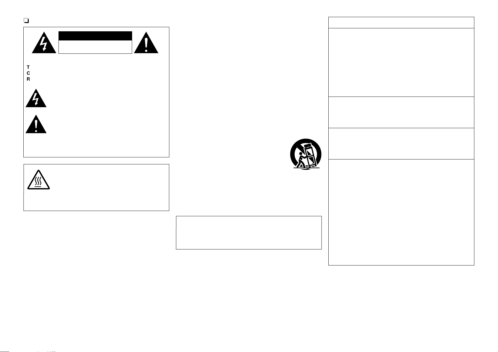
CAUTION
RISK OF ELECTRIC SHOCK
DO NOT OPEN
CAUTION:
TO REDUCE THE RISK OF ELECTRIC SHOCK, DO NOT REMOVE
COVER (OR BACK). NO USER-SERVICEABLE PARTS INSIDE.
REFER SERVICING TO QUALIFIED SERVICE PERSONNEL.
The lightning flash with arrowhead symbol, within an equilateral
triangle, is intended to alert the user to the presence of
uninsulated “dangerous voltage” within the product’s enclosure
that may be of sufficient magnitude to constitute a risk of
electric shock to persons.
The exclamation point within an equilateral triangle is intended
to alert the user to the presence of important operating
and maintenance (servicing) instructions in the literature
accompanying the appliance.
WARNING:
TO REDUCE THE RISK OF FIRE OR ELECTRIC SHOCK, DO NOT
EXPOSE THIS APPLIANCE TO RAIN OR MOISTURE.
CAUTION:
HOT SURFACE. DO NOT TOUCH.
The top surface over the internal heat sink may become hot
Hot
surface
mark
when operating this product continuously.
Do not touch hot areas, especially around the “Hot surface
mark” and the top panel.
INSTRUCTIONS
1. Read these instructions.
2. Keep these instructions.
3. Heed all warnings.
4. Follow all instructions.
5. Do not use this apparatus near water.
6. Clean only with dry cloth.
7. Do not block any ventilation openings.
Install in accordance with the manufacturer’s instructions.
8. Do not install near any heat sources such as radiators, heat registers,
stoves, or other apparatus (including amplifiers) that produce heat.
9. Do not defeat the safety purpose of the polarized or grounding-type plug. A
polarized plug has two blades with one wider than the other. A grounding
type plug has two blades and a third grounding prong. The wide blade or the
third prong are provided for your safety. If the provided plug does not fit into
your outlet, consult an electrician for replacement of the obsolete outlet.
10. Protect the power cord from being walked on or pinched particularly at
plugs, convenience receptacles, and the point where they exit from the
apparatus.
11. Only use attachments/accessories specified by the manufacturer.
12. Use only with the cart, stand, tripod, bracket, or table
specified by the manufacturer, or sold with the apparatus.
When a cart is used, use caution when moving the cart/
apparatus combination to avoid injury from tip-over.
13. Unplug this apparatus during lightning storms or when
unused for long periods of time.
14. Refer all servicing to qualified service personnel.
Servicing is required when the apparatus has been damaged in any way,
such as power-supply cord or plug is damaged, liquid has been spilled or
objects have fallen into the apparatus, the apparatus has been exposed to
rain or moisture, does not operate normally, or has been dropped.
15. Batteries shall not be exposed to excessive heat such as sunshine, fire or
the like.
CAUTION:
To completely disconnect this product from the mains, disconnect the plug
from the wall socket outlet.
The mains plug is used to completely interrupt the power supply to the unit
and must be within easy access by the user.
1. COMPLIANCE INFORMATION
Product Name: Integrated Network AV Receiver
Model Number: AVR-3313CI
This product complies with Part 15 of the FCC Rules. Operation is subject
to the following two conditions: (1) this product may not cause harmful
interference, and (2) this product must accept any interference received,
including interference that may cause undesired operation.
Denon Electronics (USA), LLC
(a D&M Holdings Company)
100 Corporate Drive
Mahwah, NJ 07430-2041
Tel. (201) 762 -6665
2. IMPORTANT NOTICE: DO NOT MODIFY THIS PRODUCT
This product, when installed as indicated in the instructions contained
in this manual, meets FCC requirements. Modification not expressly
approved by DENON may void your authority, granted by the FCC, to use
the product.
3. IMPORTANT
When connecting this product to network hub or router, use only a
shielded STP or ScTP LAN cable which is available at retailer.
Follow all installation instructions. Failure to follow instructions could void
your authority, granted by the FCC, to use the product.
4. NOTE
This product has been tested and found to comply with the limits for
a Class B digital device, pursuant to Part 15 of the FCC Rules. These
limits are designed to provide reasonable protection against harmful
interference in a residential installation.
This product generates, uses and can radiate radio frequency energy and,
if not installed and used in accordance with the instructions, may cause
harmful interference to radio communications. However, there is no
guarantee that interference will not occur in a particular installation. If this
product does cause harmful interference to radio or television reception,
which can be determined by turning the product OFF and ON, the user
is encouraged to try to correct the interference by one or more of the
following measures:
•Reorientorrelocatethereceivingantenna.
•Increasetheseparationbetweentheequipmentandreceiver.
•Connect the productintoan outlet on acircuitdifferent from that to
which the receiver is connected.
•Consultthelocalretailerauthorizedtodistributethistypeofproductor
an experienced radio/TV technician for help.
For Canadian customers:
This Class B digital apparatus complies with Canadian ICES-003.
I
Page 3
NOTES ON USE
Basic version
Advanced version
Informations
DVD
n
n CAUTIONS ON INSTALLATION
WARNINGS
•Avoid high temperatures.
Allow for sufficient heat dispersion when installed in a rack.
•Handle the power cord carefully.
Hold the plug when unplugging the cord.
•Keep the unit free from moisture, water, and dust.
•Unplug the power cord when not using the unit for long periods of time.
•Do not obstruct the ventilation holes.
•Do not let foreign objects into the unit.
•Do not let insecticides, benzene, and thinner come in contact with the unit.
•Never disassemble or modify the unit in any way.
•Ventilation should not be impeded by covering the ventilation openings
with items, such as newspapers, tablecloths or curtains.
•Naked flame sources such as lighted candles should not be placed on
the unit.
•Observe and follow local regulations regarding battery disposal.
•Do not expose the unit to dripping or splashing fluids.
•Do not place objects filled with liquids, such as vases, on the unit.
•Do not handle the mains cord with wet hands.
•When the switch is in the OFF (STANDBY) position, the equipment is not
completely switched off from MAINS.
•The equipment shall be installed near the power supply so that the power
supply is easily accessible.
z
z z
z
Wall
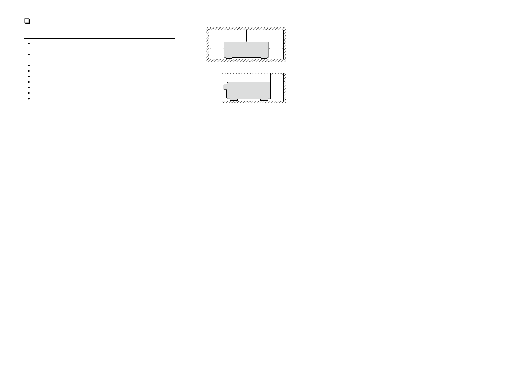
z For proper heat dispersal, do not install this unit in a confined
space, such as a bookcase or similar enclosure.
•More than 12 in. (0.3 m) is recommended.
•Do not place any other equipment on this unit.
II
Page 4
Getting started
Basic version
Advanced version
Informations
DVD
Thank you for purchasing this DENON product. To ensure proper operation, please read this owner’s manual carefully before using the product.
After reading them, be sure to keep them for future reference.
Contents
Getting started ·············································································· 1
Accessories ··················································································2
Features ························································································ 2
Cautions on handling ····································································3
Basic version ············································································4
Connections ··················································································· 5
Important information ··································································· 5
Connecting an HDMI-compatible device ······································ 8
Connecting an HDMI-incompatible device ·································14
Connecting a external power amplifier ······································· 25
Connecting an external control device ········································26
Connecting to a home network (LAN) ········································ 27
Connecting the power cord ························································ 28
Setup ···························································································· 29
Set up speakers (Audyssey® Setup) ·········································· 29
Making the network settings (Network) ····································· 35
Playback (Basic operation) ························································· 36
Important information ································································· 36
Playing a Blu-ray Disc player/DVD player ···································· 37
Playing a Blu-ray Disc player compatible with Denon Link HD ··· 37
Playing Super Audio CD ······························································ 38
Playing a CD player ····································································· 38
Playing an iPod············································································39
Playing a USB memory device ····················································42
Listening to HDRadio stations ··················································· 45
Network contents ·······································································54
Listening to internet radio ··························································· 54
Playing back files stored on a PC and NAS ································· 57
Using online services ·································································· 61
Convenient functions ·································································· 69
AirPlay function ··········································································· 73
Selecting a listening mode (Sound Mode) ·······························75
Selecting a listening mode··························································75
Advanced version ································································81
Installation/connection/setup of speakers (Advanced) ··········82
Speaker installation ····································································· 82
Speaker connection ···································································· 84
Set up speakers ·········································································· 92
Playback (Advanced operation) ················································· 95
HDMI control function ································································ 95
Sleep timer function ···································································97
Quick select function ·································································· 98
REC OUT mode ·········································································· 99
Web control function ································································ 100
Various memory functions ························································ 102
Playback in ZONE2/ZONE3 (Separate room) ·························103
Audio output ············································································· 103
Video output ·············································································104
Playback ···················································································· 105
Sleep timer function ·································································105
How to make detailed settings ················································ 106
Menu map ················································································106
Examples of menu screen displays ·········································· 108
Examples of menu and front display ········································109
Inputting characters ·································································· 110
Audio·························································································112
Video ························································································· 119
Inputs ························································································ 124
Speakers ··················································································· 129
Network ···················································································· 135
General ·····················································································139
Operating external devices with the remote control ············145
Registering preset codes ·························································· 145
Operating external devices ······················································· 148
Operating devices ····································································· 149
Specifying the zone used with the remote control unit ············ 151
Resetting the remote control unit ·············································151
Informations·········································································152
Part names and functions·························································153
Front panel ················································································ 153
Display ······················································································ 155
Rear panel ················································································· 156
Remote control unit ·································································· 157
Other information ·····································································159
Trademark information ······························································159
Surround ··················································································· 160
Relationship between video signals and monitor output ·········· 166
Explanation of terms ································································· 168
Troubleshooting ········································································ 171
Resetting the microprocessor ··················································176
Specifications ············································································177
1
Page 5
Accessories
Basic version
Advanced version
Informations
v See overleaf
DVD
Check that the following parts are supplied with the product.
q Getting Started ........................................................................ 1
w CD-ROM (Owner’s manual) .................................................... 1
e Safety Instructions .................................................................. 1
r Warranty (for North America model only) ................................ 1
t Service network list ................................................................. 1
y Power cord .............................................................................. 1
u Remote control unit (RC-1166) ................................................ 1
i R6/AA batteries ....................................................................... 2
o Setup microphone (ACM1HB) ................................................. 1
Q0 AM loop antenna ..................................................................... 1
Q1 FM indoor antenna .................................................................. 1
Q0
u
Q1
oy
Features
Digital video processor up-scales analog video
signals (SD resolution) to 4K
This unit is equipped with the 4K video upscaling function, which
allows for outputting analogue or SD (standard video quality) video
to HDMI at 4K (3840 × 2160 pixels). This enables the unit and a TV
connected with a single HDMI cable and any video source to be
reproduced precisely with HD level of quality.
DENON’s unique high quality playback technology
“Denon Link HD”
By connecting to a DENON Blu-ray Disc player compatible with
Denon Link HD, the sound localization becomes more precise,
reproducing a clear and three-dimensional sound image. Because
this unit makes the integrated circuits operate while sharing the
same clock with the Blu-ray Disc player, the transmitted digital
audio has less jitter. This effect applies to any media audio source
from the Blu-ray Disc player.
With a discrete-circuit configuration, the power
amplifier provides identical quality for all 7
channels (165 W x 7ch)
The unit is equipped with a power amplifier that reproduces
highfidelity sound in sound mode with equal quality and power for
all channels, true to the original sound.
The power amplifier circuit adopts a discrete-circuit configuration
that achieves high-quality surround sound reproduction.
Supports internet radio, music, and photograph
streaming
Supports AirPlay® (vpage73)
You can enjoy a wide variety of content, including listening
to Internet radio, playing the audio files stored on your PC, and
displaying on a TV the photographs stored on your PC.
This unit also supports AirPlay that lets you stream your music
library from an iPhone, iPad, iPod touch or iTunes.
Equipped with “Hybrid PLL Jitter Reducer”
capable of reducing jitter and phase noise that
negatively affect sound quality
“Hybrid PLL Jitter Reducer” provided with this unit improves the
sound localization, reproducing a natural sound field.
Equipped with a Multi-Zone Function 3 source, 3
zone output (incl.HDMI output for ZONE2)
This unit is equipped with a multi-zone function, so you can enjoy
separate sound sources in three rooms including MAIN ZONE.
Furthermore, this unit is equipped with an HDMI ZONE2 OUT
connector, so you can play back in ZONE2 a video that is different
from the one played back in MAIN ZONE.
Compatible with “Denon Remote App” for
performing basic operations of the unit with an
iPad, iPhonez1 or Android smartphone
“Denon Remote App” is application software that allows you to
perform basic operations with an iPad, iPhone, Android smartphone
or Android tablet such as turning the unit ON/OFF, controlling the
volume, and switching the source.
z1 Download “Denon Remote App” from iTunes® App Store.
The unit needs to be connected to a LAN and the iPhone/iPod
touch needs to be connected to the same network by Wi-Fi
(wireless LAN).
2
Page 6

“Setup Assistant”, providing easy-to-follow setup
Basic version
Advanced version
Informations
DVD
instructions
First select the language when prompted. Then simply follow the
instructions displayed on the TV screen to set up the speakers,
network, etc.
Easy to use, Graphical User Interface
This unit is equipped with an easy to see “Graphical User Interface”
that uses menu displays and levels. The use of level displays
increases operability of the this unit.
HDMI connectors enable connection to various
digital AV devices (input: 7, output: 3)
The unit is equipped with 7 HDMI input connectors for connecting
devices with HDMI connectors, such as a Blu-ray Disc player,
game machine, HD digital camcorder, etc.
Supports HDMI (3D, ARC, Deep Color, “x.v.Color”,
Auto Lip Sync, 4K) and HDMI control function
(vpage8)
In addition to HDMI 3D and ARC (Audio Return Channel) functions,
this unit supports the video pass-through function, which outputs
video to TV without changing the video quality when video signals
of 4K (3840×2160 pixels) are input, and the GUI overlay function,
which overlays the menu screen (GUI) on the 4K video screen.
Features
Simultaneous playback on two HDMI channels
(except for ZONE2 HDMI output)
This unit is equipped with two HDMI MONITOR outputs. You can
connect one output to a projector and the other output to a TV for
simultaneous signal outputs.
Direct play for iPod® and iPhone® via USB
(vpage21)
Music data from an iPod can be played back if you connect the USB
cable supplied with the iPod via the USB port of this unit, and also
an iPod can be controlled with the remote control unit for this unit.
Audyssey DSX
This unit is equipped with Audyssey DSX® processor. By
connecting front height speakers to this unit and playing back
through Audyssey DSX®, you can experience a more powerful
playback expression in the height audio range. By connecting front
wide speakers, you can experience a more powerful playback
expression in the wide audio range.
®
Cautions on handling
•Before turning the power on
Check once again that all connections are correct and that there are
no problems with the connection cables.
•Power is supplied to some of the circuitry even when the unit is
set to the standby mode. When going on vacation or leaving home
for long periods of time, be sure to unplug the power cord from the
power outlet.
•About condensation
If there is a major difference in temperature between the inside of
the unit and the surroundings, condensation (dew) may form on
the operating parts inside the unit, causing the unit not to operate
properly.
If this happens, let the unit sit for an hour or two with the power
turned off and wait until there is little difference in temperature
before using the unit.
•Cautions on using mobile phones
Using a mobile phone near this unit may result in noise. If that
occurs, move the mobile phone away from this unit when it is in use.
•Moving the unit
Turn off the power and unplug the power cord from the power
outlet. Next, disconnect the connection cables to other system units
before moving the unit.
•About care
•Wipe the cabinet and control panel clean with a soft cloth.
•Follow the instructions when using a chemical cleaner.
•Benzene, paint thinner or other organic solvents as well as
insecticide may cause material changes and discoloration if brought
into contact with the unit, and should therefore not be used.
3
Page 7

Basic version
Basic version
Advanced version
Informations
Basic version
DVD
Basic version
Here, we explain the connections and basic operation methods for this unit.
F Connections vpage5
F Setup vpage29
F Playback (Basic operation) vpage36
F Selecting a listening mode (Sound Mode) vpage75
4
Page 8
Connections
Basic version
Advanced version
Informations
Basic version
DVD
Important information
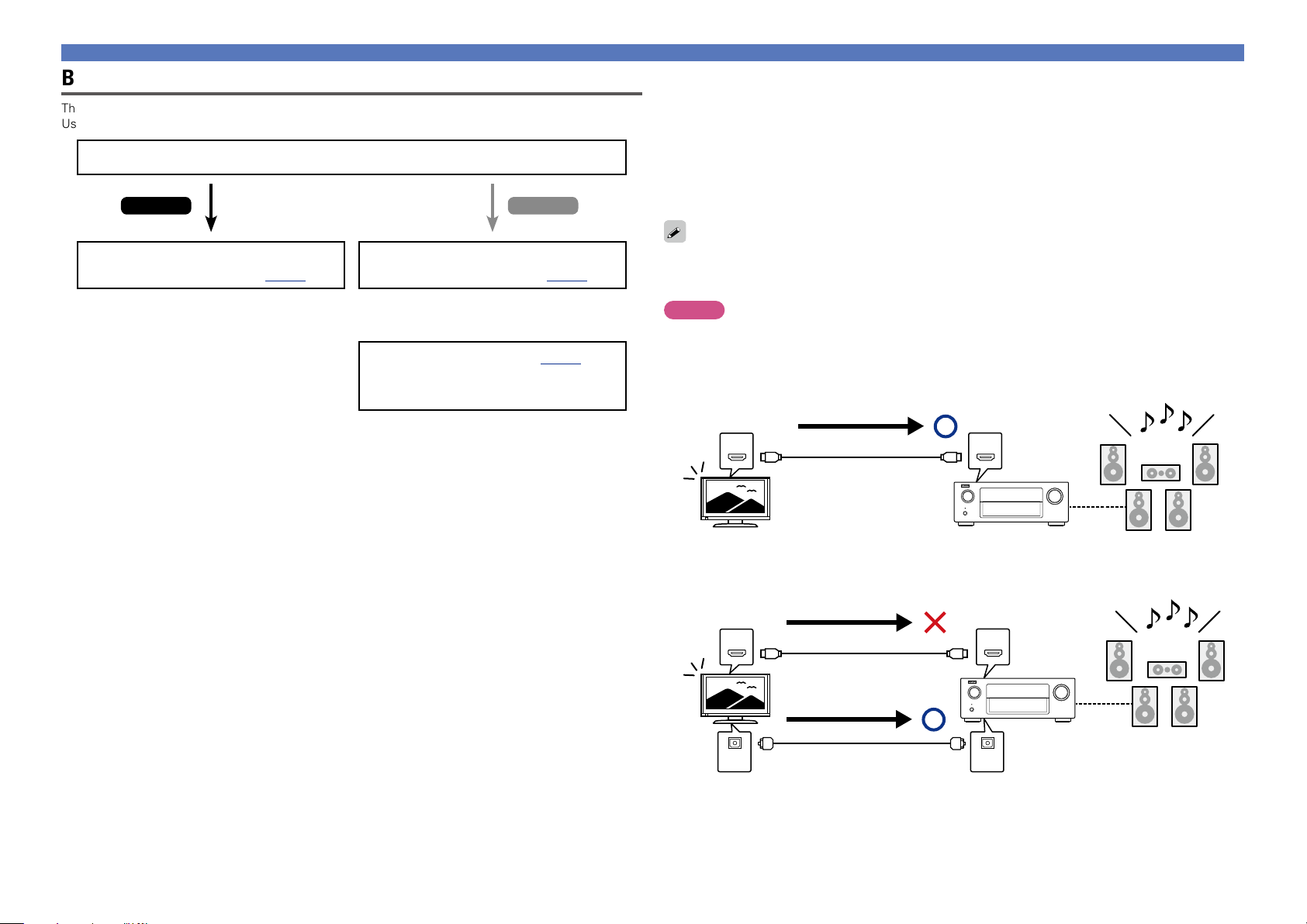
Make connections before using this unit.
To create a home theater that can play back higher quality video and audio by fully utilizing the
capabilities of this unit and your video devices, connect this unit to each of your video devices with
HDMI cables.
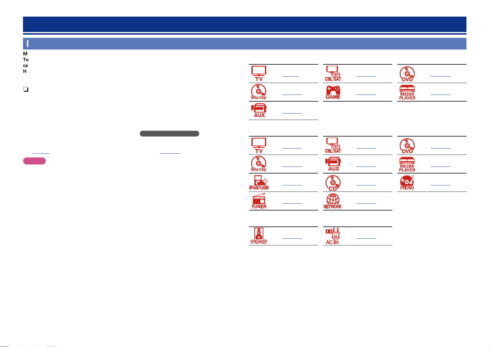
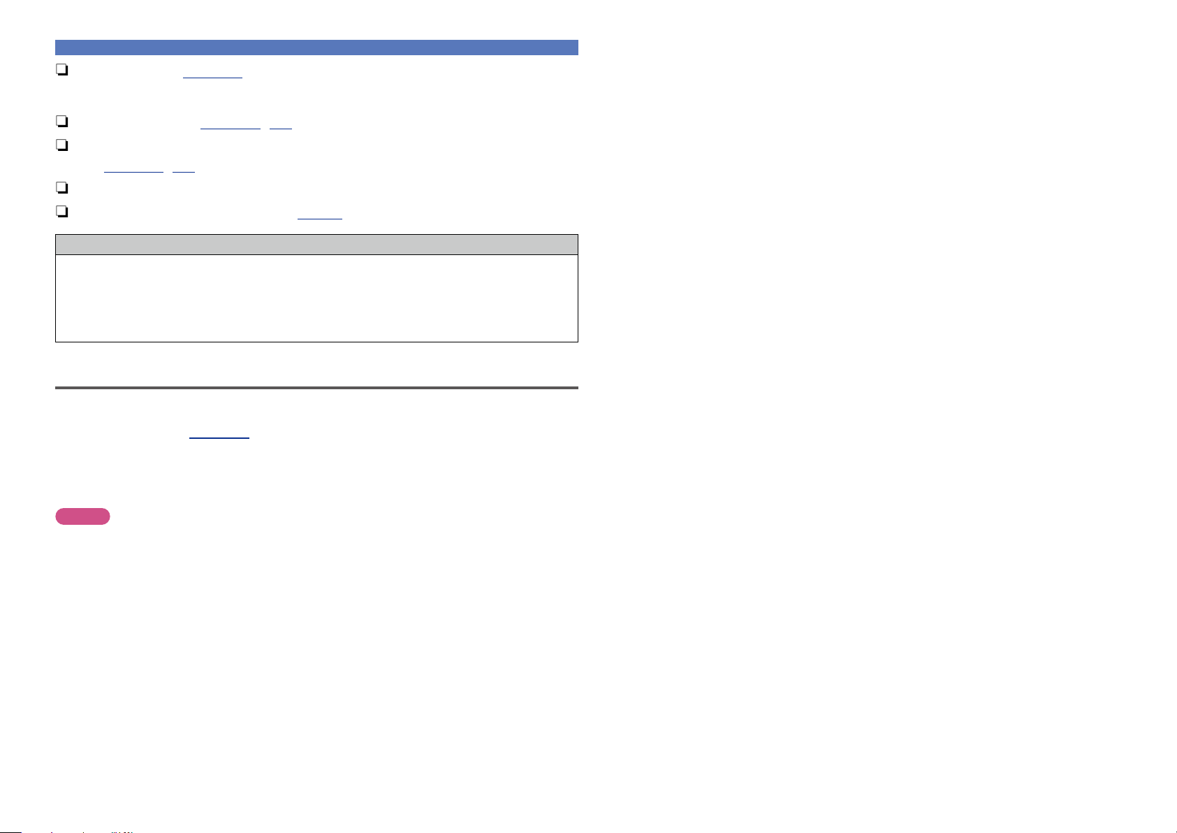
n HDMI-compatible device
vpage9 vpage11 vpage11
n HDMI-compatible device
If your video device does not support HDMI connections, use the following connection.
n HDMI-incompatible device
This unit can change the source that is assigned to the DIGITAL AUDIO IN and COMPONENT VIDEO
IN connectors.
You can change the source for connectors listed in Input connector setting within pages that
describe connections for devices.
For details on assigning a source to connectors, see “Changing the source assigned to connectors”
(vpage14). For the setting method, see “Input Assign” (vpage125).
NOTE
•The menu screen is only displayed on TV connected to this unit via HDMI. If your TV is connected
to this unit via other video output connectors, perform menu operations while seeing the display
on this unit.
•Do not plug in the power cord until all connections have been completed. However, when the “Setup
Assistant” is running, follow the instructions in the “Setup Assistant” (C page 7) screen for making
connections. (During “Setup Assistant” operation, the input/output connectors do not conduct current.)
•When running the “Setup Assistant” (C page 7), turn off the power supply of connected devices.
•When making connections, also refer to the operating instructions of the other devices being connected.
•Be sure to connect the left and right channels properly (left with left, right with right).
•Do not bundle power cords together with connection cables. Doing so can result in noise.
vpage11 vpage11 vpage11
vpage11
n HDMI-incompatible device
vpage15 vpage16 vpage18
vpage18 vpage19 vpage20
vpage21 vpage22 vpage23
vpage24 vpage27
n Others
vpage84 vpage28
5
Page 9
Important information
Basic version
Advanced version
Informations
Basic version
DVD
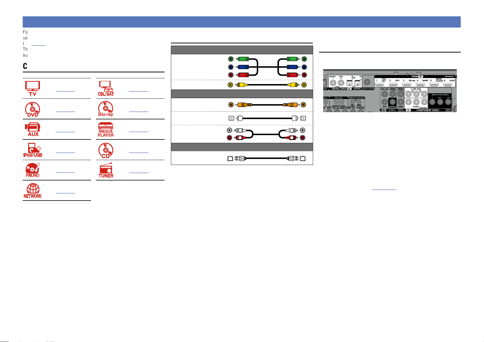
Converting input video signals for output (Video conversion function)
This unit is equipped with three types of video input connectors (HDMI, Component video and video) and three types of video output connectors
(HDMI, Component video and video).
This function automatically converts various formats of video signals input to this unit into the formats used to output the video signals from
this unit to a monitor.
GFlow of video signals for MAIN ZONEH
Video device
Output
HDMI connector
This unit
Input
(IN)
HDMI signal HDMI signal
HDMI connector
Component video
signal
Output
(MONITOR OUT)
Component video
Component video
signal
signal
HDMI-compatible TV
Input
HDMI connectorHDMI connector
HDMI-incompatible
TV
Make Settings as Necessary
•If you do not want this unit to convert video signals automatically,
use the following setting item to disable this function.
“Video Conversion” (vpage121)
•If you want to change the resolution of video signals output to
the TV, use the following setting item to do so.
“Resolution” (vpage122)
•The video conversion function supports the NTSC, PAL, SECAM,
NTSC 4.43, PAL-N, PAL-M and PAL-60 formats.
•Resolutions of HDMI-compatible TVs can be checked at “Video” –
“Monitor” (vpage142).
NOTE
•The menu screen is only displayed on TV connected to this unit
via HDMI. If your TV is connected to this unit via other video
output connectors, perform menu operations while seeing the
display on this unit.
•HDMI signals are digital. HDMI signals cannot be converted into
analog signals.
•When a non-standard video signal from a game machine or some
other source is input, the video conversion function might not
operate.
Component video
connectors
Video signal Video signal
Video connector
For example, if you connect this unit to an HDMI-compatible TV with a single HDMI cable, this unit automatically converts input signals other
than HDMI video signals to HDMI signals to output from the HDMI connector to the TV. This unit outputs only one type of video signals, so
video signals output from this unit to the TV remain unchanged even if you switch to a device that outputs another type of video signals for
playback. Therefore, you do not need to switch the video input on the TV. Furthermore, this unit converts the input analog video signals such as
video and component video signals to high resolution digital HDMI video signals for output, improving the quality of the video.
If your TV does not support HDMI connections, connect this unit to TV with analog video connectors. This unit can not convert HDMI input
signals to analog video signals, so when inputting from an HDMI device, use component video or video input connectors.
Component video
connectors
Video connector Video connector
Component video
connectors
Component video
connectors
Video connector
6
NOTE
•HDMI signals are digital. HDMI signals cannot be converted into
analog signals.
•The HDMI ZONE function is only compatible with the HDMI 1-6 IN
connectors. It is not compatible with the HDMI 7 IN connector.
Page 10
Important information
Basic version
Advanced version
Informations
Basic version
DVD
Video device
Output
HDMI connector
Component video
connectors
Video connector
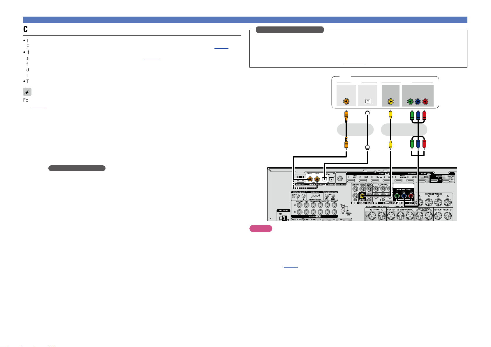
GFlow of video signals for ZONE2H
This unit
Input
(IN)
HDMI signal HDMI signal
HDMI connector
Component video
signal
Component video
connectors
Video signal Video signal
Video connector Video connector
(ZONE2 MONITOR OUT)
Output
Component video
connectors
Component video
Component video
signal
signal
HDMI-compatible TV
Input
HDMI connectorHDMI connector
HDMI-incompatible
TV
Component video
connectors
Video connector
NOTE
•HDMI signals are digital. HDMI signals cannot be converted into
analog signals.
•The HDMI ZONE function is only compatible with the HDMI 1-6 IN
connectors. It is not compatible with the HDMI 7 IN connector.
7
Page 11
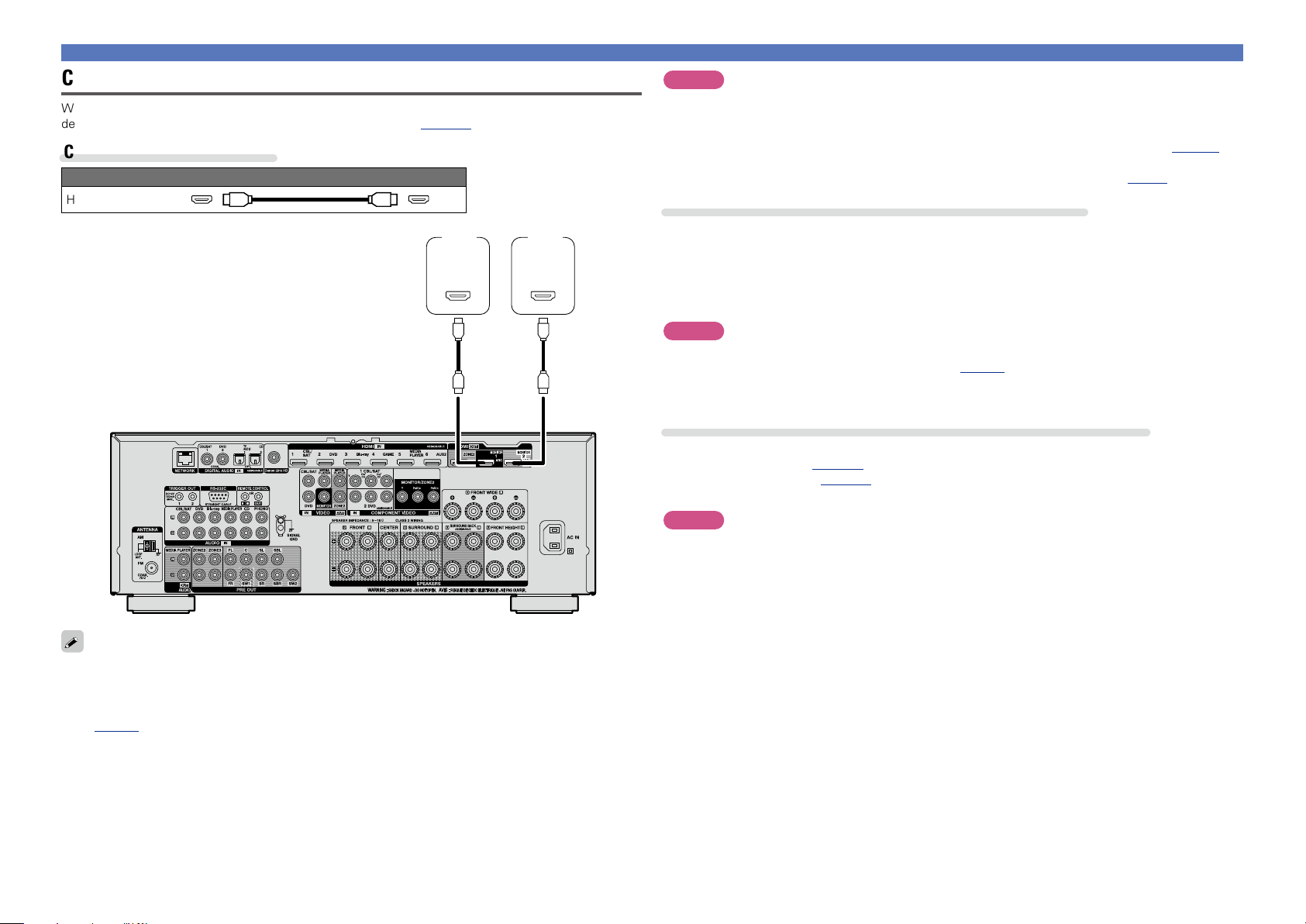
Connecting an HDMI-compatible device
Basic version
Advanced version
Informations
Basic version
DVD
You can connect up to ten HDMI-compatible devices (7-inputs/3-outputs) to the unit.
When a TV is connected to the HDMI ZONE2 OUT connector, you can play back a video or audio from the
device connected to the HDMI 1 - 6 IN connector in ZONE2 ( vpage103).
If the device connected to this unit is equipped with an HDMI connector, it is recommended to use HDMI
connections. Connections with an HDMI cable offer the following benefits that can not be achieved with
other connection methods.
•High quality playback by transmitting audio and video via digital signals
HDMI connections can transmit high definition video and high quality audio formats adopted by Bluray disc players (Dolby Digital Plus, Dolby TrueHD, dts-HD, dts-HD Master Audio).
HDMI connections also convey information required for playback between devices. The information
is used for copyright protection and TV resolution recognition, the ARC function, the HDMI control
function, etc.
•Transmission of audio and video signals with a single HDMI cable
Previous connections require multiple audio and video cables, but HDMI connections require only a
single HDMI cable to transmit audio and video signals. This allows wires in a home theater system,
which tend to be complicated, to be more organized.
•Mutual control through the HDMI control function (vpage95)
This unit and the HDMI device connected via HDMI can be linked to perform operations such as
power control, volume control, and input source switching.
•Other video and audio functions, such as 3D video playback, Content Type, the ARC function,
are supported (vpage12).
•There is more than one version of HDMI standard. The supported functions and the performance vary
according to the version. This unit complies with the HDMI standard, supporting the ARC and 3D playback
functions. To enjoy these functions, the HDMI device connected to this unit also needs to use the same
version of the standard. For the version of the HDMI standard on the device connected to this unit, see
the device’s manual.
•Some TVs do not support audio input via HDMI connections. For details, see your TV’s manual.
n Before connecting this unit to TV via HDMI connections (vpage9)
n Connecting this unit to a TV via HDMI connections (vpage10)
n Connecting this unit to video devices via HDMI connections (vpage11)
n HDMI function (vpage12)
n Settings related to HDMI connections (vpage13)
8
Page 12
Before connecting this unit to TV via HDMI connections
Basic version
Advanced version
Informations
Basic version
DVD
There are 2 methods to connect HDMI-compatible TV to this unit.
Use the connection method that suits your TV.
Does the TV to be connected to this unit support the ARC function?
Yes No
Connecting an HDMI-compatible device
n About ARC (Audio Return Channel) function
This function plays TV audio on this unit by sending the TV audio signal to this unit via HDMI cable.
If a TV without the ARC function is connected via HDMI connections, video signals of the playback
device connected to this unit are transmitted to the TV, but this unit can not play back the audio from
the TV. If you want to enjoy surround audio for TV program, a separate audio cable connection is
required.
In contrast, if a TV with the ARC function is connected via HDMI connections, no audio cable connection
is required. Audio signals from the TV can be input to this unit through the HDMI cable between this
unit and the TV. This function allows you to enjoy surround playback on this unit for the TV.
Connecting this unit to a TV via
HDMI connections (vpage10)
Connecting this unit to a TV via
HDMI connections (vpage10)
+
Connecting a TV (vpage15)
For audio connections, use a method other
than HDMI connections.
When the ARC function is used, connect a device with a “Standard HDMI cable with Ethernet” or “High
Speed HDMI cable with Ethernet” for HDMI.
Refer to the owner’s manual for your TV for details about TV connection and settings.
NOTE
The HDMI ZONE2 OUT connector is not compatible with the ARC function.
GConnection to a TV with the ARC functionH
Audio from the TV
Audio signals from the TV
IN OUT
This unit SpeakersTV
GConnection to a TV without the ARC functionH
Audio from the TV
Audio signals from the TV
IN OUT
Audio signals from the TV
Optical cable
INOUT
9
Page 13
Connecting an HDMI-compatible device
Basic version
Advanced version
Informations
Basic version
DVD
Connecting this unit to a TV via HDMI connections
When a TV is connected to the HDMI ZONE2 OUT connector, you can play back a video or audio from the
device connected to the HDMI 1 - 6 IN connector in ZONE2 ( vpage103).
Cables used for connections
Audio and video cable (sold separately)
HDMI cable
TV 1 TV 2
HDMI
IN
(ARC)
HDMI
IN
(ARC)
NOTE
•The audio signal from the HDMI output connector (sampling frequency, number of channels, etc.) may be
limited by the HDMI audio specifications of the connected device regarding permissible inputs.
•When connecting a TV that does not support the ARC function, an audio cable connection is
required in addition to the HDMI cable. In this case, refer to “Connecting a TV” (vpage15) for
the connection method.
For the ARC function, see “About ARC (Audio Return Channel) function” (vpage9).
Connecting to a device equipped with a DVI-D connector
The DVI-D (Digital Visual Interface) method is also used for video transmission via digital signals. This is
developed mainly for computers, and some AV devices such as projectors are equipped with this interface.
To output HDMI video signals to a DVI-D video input compatible device, use an HDMI/DVI conversion
cable, which converts HDMI video signals to DVI signals.
The DVI-D connector can transmit high quality digital signals, but the copy guard and other issues may
hinder normal operations for some device combinations.
NOTE
•No sound is output when connected to a device equipped with a DVI-D connector. Make audio
connections as described in “Connecting a TV” (vpage15).
•Signals cannot be output to DVI-D devices that do not support HDCP.
•Depending on the combination of devices, the video signals may not be output.
Settings required when using a TV that supports the ARC function
When using a TV that supports the ARC function, make the following settings.
•Set “HDMI Control” (vpage121) to “On”.
•Set “Control Monitor” (vpage121) to match the number of the HDMI MONITOR connector connected
to the TV that supports the ARC function.
NOTE
If the TV that supports the ARC function is connected to both HDMI MONITOR 1 and HDMI MONITOR 2
connectors, you cannot use ARC function at the same time.
•Video signals are not output if the input video signals do not match the monitor’s resolution. In this case,
switch the Blu-ray Disc/DVD player’s resolution to a resolution with which the monitor is compatible.
•When this unit and monitor are connected with an HDMI cable, if the monitor is not compatible with
HDMI audio signal playback, only the video signals are output to the monitor. Make audio connections
(vpage15 “Connecting a TV”).
10
Page 14
VIDEO
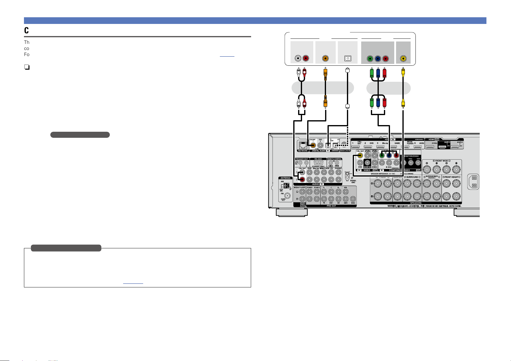
Connecting this unit to video devices via HDMI connections
Basic version
Advanced version
Informations
Basic version
v See overleaf
DVD
Cables used for connections
Audio and video cable (sold separately)
HDMI cable
•This interface allows transfer of digital video signals and digital audio signals over a single HDMI cable.
Set-top
box
HDMI
OUT
DVD
player
HDMI
OUT
Blu-ray
Disc
player
HDMI
OUT
Game
console
HDMI
OUT
Media
player
HDMI
OUT
Digital
camcorder
(Secondary)
HDMI
OUT
Connecting an HDMI-compatible device
Digital
camcorder
(Primary)
HDMI
OUT
ZONE 2
ZONE 3
SOURCE SELECT
REC SOURCE
SOURCE SELECT
ON/OFF ON/OFF
•When this unit is connected to other devices with HDMI cables, connect this unit and TV also with an
HDMI cable.
•When connecting a device that supports Deep Color or 4K, please use a “High Speed HDMI cable” or
“High Speed HDMI cable with Ethernet”.
•Video signals are not output if the input video signals do not match the monitor’s resolution. In this case,
switch the Blu-ray Disc/DVD player’s resolution to a resolution with which the monitor is compatible.
STATUS
PHONES
INFO OPTION
ENTER
BACK SETUP
GFront panelH
DIMMER
GRear panelH
11
Page 15
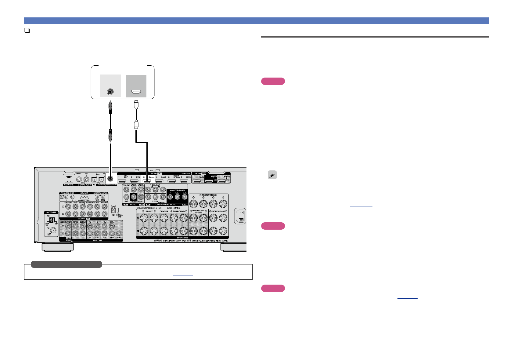
n Connecting a player compatible with the Denon Link HD function
Basic version
Advanced version
Informations
Basic version
v See overleaf
DVD
By making a Denon Link HD connection to a player compatible with the Denon Link HD function, you
can enjoy higher quality playback compared with when only the HDMI connector connection is made.
For the playback method, see “Playing a Blu-ray Disc player compatible with Denon Link HD”
(vpage37).
Blu-ray Disc player
Denon
Link HD
HDMI
OUT
Connecting an HDMI-compatible device
HDMI function
This unit supports the following HDMI functions:
n About 3D function
This unit supports input and output of 3D (3 dimensional) video signals of HDMI.
To play back 3D video, you need a TV and player that provide support for the HDMI 3D function and a
pair of 3D glasses.
NOTE
•When playing back 3D video, refer to the instructions provided in the manual of your playback device
together with this manual.
•When playing back 3D video content, the menu screen or status display screen can be superimposed
over the image. However, the menu screen or status display screen cannot be superimposed over
certain 3D video content.
•If 3D video with no 3D information is input, the menu screen and status display on this unit are displayed
over the playback video.
•If 2D video is converted to 3D video on the television, the menu screen and status display on this unit
are not displayed correctly. To view the menu screen and status display on this unit correctly, turn the
television setting that converts 2D video to 3D video off.
n About 4K function
This unit supports input and output of 4K (3840 x 2160 pixels) video signals of HDMI.
When a device supporting 4K is connected, use a cable compatible with “High Speed HDMI cable” or
“High Speed HDMI cable with Ethernet”.
When using this connection, set “DIGITAL” in “Input Assign” (vpage125) to “D.LINK”.
Input connector setting
n HDMI control function (vpage95)
This function allows you to operate external devices from the unit and operate the unit from external
devices.
NOTE
•The HDMI control function may not work depending on the device it is connected to and its settings.
•You cannot operate a TV or Blu-ray Disc player/DVD player that is not compatible with the HDMI control
function.
•The HDMI ZONE2 function is not compatible with the HDMI control function.
n About Content Type
This function was added with the HDMI standard. It automatically makes settings suitable for the videooutput type (content information).
NOTE
To enable the Content Type, set “Video Mode” to “Auto” (vpage121).
12
Page 16
Connecting an HDMI-compatible device
Basic version
Advanced version
Informations
Basic version
DVD
n Deep Color (vpage168)
When a device supporting Deep Color is connected, use a cable compatible with “High Speed HDMI
cable” or “High Speed HDMI cable with Ethernet”.
n Auto Lip Sync (vpage120, 168)
n “x.v.Color”, sYCC601 color, Adobe RGB color, Adobe YCC601 color
(vpage168, 170)
n High definition digital audio format
n ARC (Audio Return Channel) (vpage9)
Copyright protection system
In order to play back digital video and audio such as BD-Video or DVD-Video via HDMI connection, both
this unit and TV or the player need to support the copyright protection system known as HDCP (Highbandwidth Digital Content Protection System). HDCP is copyright protection technology comprised of
data encryption and authentication of the connected AV devices. This unit supports HDCP.
•If a device that does not support HDCP is connected, video and audio are not output correctly. Read
the owner’s manual of your television or player for more information.
Settings related to HDMI connections
Set as necessary. For details, see the respective reference pages.
n HDMI Setup (vpage120)
Make settings for HDMI video/audio output.
•Auto Lip Sync •HDMI Control •Power Off Control
•HDMI Audio Out •Standby Source
•Video Output •Control Monitor
NOTE
The audio signal input from the HDMI input connector can be output as an output signal from the HDMI
output connector by setting the HDMI audio output destination to TV.
Audio signals input via the Analog/Coaxial/Optical input connectors cannot be output from the HDMI
MONITOR output connector.
13
Page 17
Connecting an HDMI-incompatible device
Basic version
Advanced version
Informations
Basic version
DVD
For high quality video and surround playback, it is recommended to
use an HDMI cable to connect this unit to TV and other video devices
(vpage8 “Connecting an HDMI-compatible device”).
This section describes connections when your device does not
support HDMI connections.
Connection methods for various devices
Cables used for connections
Component video
cable
Video cable (sold separately)
Changing the source assigned to
connectors
This unit can change the source that is assigned to the HDMI IN,
DIGITAL AUDIO IN and COMPONENT VIDEO IN connectors.
vpage15 vpage16
vpage18 vpage18
vpage19
vpage20
vpage21 vpage22
vpage23
vpage24
vpage27
Video cable
Coaxial digital cable
Optical cable
Audio cable
Ethernet cable
Audio cable (sold separately)
L
R
Cable (sold separately)
Let us take a digital audio connection for Blu-ray Disc players for an
L
R
example. The rear panel digital audio input connectors do not have the
input connector indication for Blu-ray disc players (Blu-ray). However,
DIGITAL AUDIO IN connectors have the “ASSIGNABLE” indication,
which means that you can change the source assigned to these
connectors. You can assign Blu-ray disc players to these connectors
to use them for Blu-ray disc players. Select “Blu-ray” when switching
functions on this unit to play back the source connected to these
connectors.
n How to change the source assigned to
connectors (vpage125)
14
Page 18
Connecting an HDMI-incompatible device
Basic version
Advanced version
Informations
Basic version
DVD
Connecting a TV
•This section describes how to connect when your TV does not support HDMI connections.
For instructions on HDMI connections, see “Connecting an HDMI-compatible device” (vpage8).
•If the TV connected to this unit is equipped with an HDMI connector that supports ARC, digital audio
signals from TV can be transmitted to this unit (vpage 9 “About ARC (Audio Return Channel)
function”). The ARC function allows you to enjoy on this unit the audio from TV programs and HDMI
devices directly connected to TV, without having to make a separate audio connection. For the ARC
function, also see your TV’s manual.
•To listen to TV audio through this device, use the optical digital connection.
For video connections, see “Converting input video signals for output (Video conversion function)”
(vpage6).
n Audio connection
The following methods are available for connecting to this unit. Use either of the methods to make
a connection.
a DIGITAL AUDIO OPTICAL connector
DIGITAL AUDIO COAXIAL connector
When a multichannel audio (digital bit stream audio) is input, this unit decodes the audio to play
back surround sound.
z When making this type of connection, you must change the settings on this unit.
(v Input connector setting )
n Video connection
The following methods are available for connecting to this unit. Use either of the methods to make
a connection.
The numbers prefixed with connectors indicate the recommendation order. The smaller the number is,
the higher playback quality is achieved.
z
Input connector setting
When making the following connection, you must change the input connector settings.
a DIGITAL AUDIO COAXIAL connector
When connecting to connectors marked as 1, change “CBL/SAT” to “TV AUDIO”.
For how to change, see “Input Assign” (vpage125).
TV
COAXIAL
OUT
OPTICAL
OUT
a a s
or or
VIDEO
IN
VIDEOAUDIO
COMPONENT VIDEO
IN
B PR
Y P
a
a COMPONENT VIDEO OUT (MONITOR) connector
This makes an analog video connection. This connection method separates video signals into 3
signals for transmission based on color components, achieving the best quality video playback
among analog video connections, with less signal degradation.
s VIDEO OUT (MONITOR) connector
This makes an analog video connection.
NOTE
•The menu screen is only displayed on TV connected to this unit via HDMI. If your TV is connected
to this unit via other video output connectors, perform menu operations while seeing the display
on this unit.
•If you do not connect this unit to your TV via HDMI, do not make HDMI connections for video inputs from
other video devices, either. For details see “Converting input video signals for output (Video conversion
function)” (vpage6).
15
Page 19
Connecting an HDMI-incompatible device
Basic version
Advanced version
Informations
Basic version
DVD
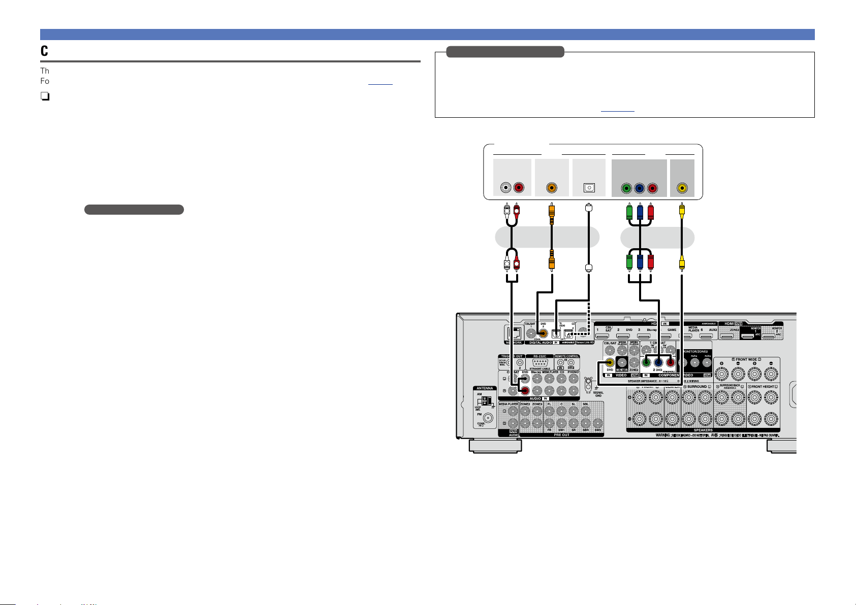
Connecting a set-top box (Satellite tuner/cable TV)
This section describes how to connect when your satellite tuner or cable TV does not support HDMI
connections.
For instructions on HDMI connections, see “Connecting an HDMI-compatible device” (vpage8).
n Audio connection
The following methods are available for connecting to this unit. Use either of the methods to make
a connection.
The numbers prefixed with connectors indicate the recommendation order. The smaller the number is,
the higher playback quality is achieved.
a DIGITAL AUDIO COAXIAL connector
DIGITAL AUDIO OPTICAL connector
When a multichannel audio (digital bit stream audio) is input, this unit decodes the audio to play
back surround sound.
z When making this type of connection, you must change the settings on this unit.
(v Input connector setting )
s AUDIO IN (CBL/SAT) connector
This makes an analog audio connection. This type of connection converts digital audio to analog
audio, so the output audio may be degraded compared to connections a.
n Video connection
The following methods are available for connecting to this unit. Use either of the methods to make
a connection.
The numbers prefixed with connectors indicate the recommendation order. The smaller the number is,
the higher playback quality is achieved.
a COMPONENT VIDEO IN (CBL/SAT) connector
This makes an analog video connection. This connection method separates video signals into 3
signals for transmission based on color components, achieving the best quality video playback
among analog video connections, with less signal degradation.
s VIDEO IN (CBL/SAT) connector
This makes an analog video connection.
z
Satellite tuner/Cable TV
AUDIO
OUT
L
COAXIAL
OUT
RL
R
a a a ss
OPTICAL
or or or
R
L
OUT
Y P
OUT
VIDEOAUDIO
B PR
COMPONENT VIDEO
VIDEO
OUT
Input connector setting
When making the following connection, you must change the input connector settings.
a DIGITAL AUDIO OPTICAL connector
When connecting to connectors marked as 1, change “TV AUDIO” to “CBL/SAT”.
For how to change, see “Input Assign” (vpage125).
16
Page 20
Connecting an HDMI-incompatible device
Basic version
Advanced version
Informations
Basic version
DVD
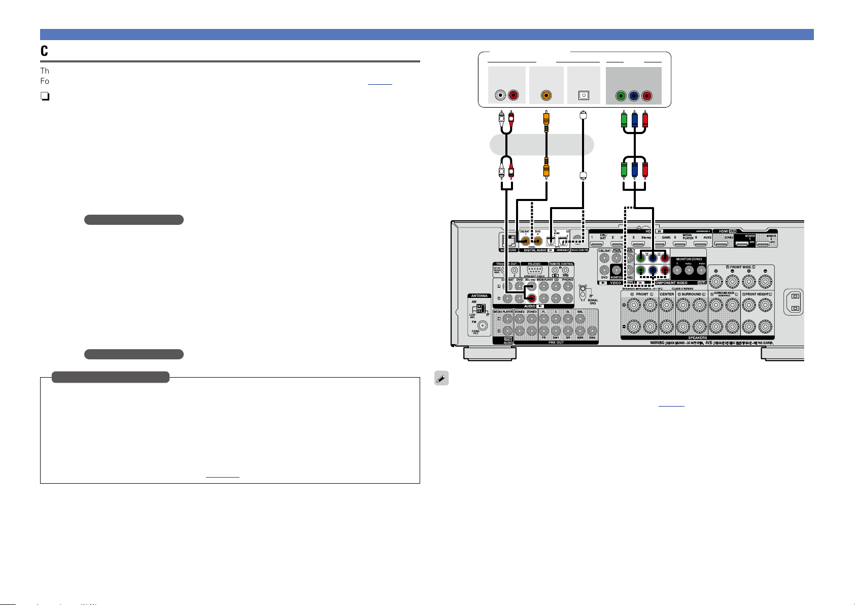
Connecting a DVD player
This section describes how to connect when your DVD player does not support HDMI connections.
For instructions on HDMI connections, see “Connecting an HDMI-compatible device” (vpage8).
n Audio connection
The following methods are available for connecting to this unit. Use either of the methods to make
a connection.
The numbers prefixed with connectors indicate the recommendation order. The smaller the number is,
the higher playback quality is achieved.
a DIGITAL AUDIO COAXIAL connector
DIGITAL AUDIO OPTICAL connector
When a multichannel audio (digital bit stream audio) is input, this unit decodes the audio to play
back surround sound.
z When making this type of connection, you must change the settings on this unit.
(v Input connector setting )
s AUDIO IN (DVD) connector
This makes an analog audio connection. This type of connection converts digital audio to analog
audio, so the output audio may be degraded compared to connections a.
n Video connection
The following methods are available for connecting to this unit. Use either of the methods to make
a connection.
The numbers prefixed with connectors indicate the recommendation order. The smaller the number is,
the higher playback quality is achieved.
a COMPONENT VIDEO IN (DVD) connector
This makes an analog video connection. This connection method separates video signals into 3
signals for transmission based on color components, achieving the best quality video playback
among analog video connections, with less signal degradation.
s VIDEO IN (DVD) connector
This makes an analog video connection.
z
Input connector setting
When making the following connection, you must change the input connector settings.
a DIGITAL AUDIO OPTICAL connector
When connecting to connectors marked as 1, change “TV AUDIO” to “DVD”.
For how to change, see “Input Assign” (vpage125).
DVD player
Y P
OUT
VIDEOAUDIO
B PR
VIDEO
OUT
AUDIO
OUT
L
COAXIAL
OUT
RL
R
a a a ss
OPTICAL
OUT
or or or
R
L
COMPONENT VIDEO
17
Page 21
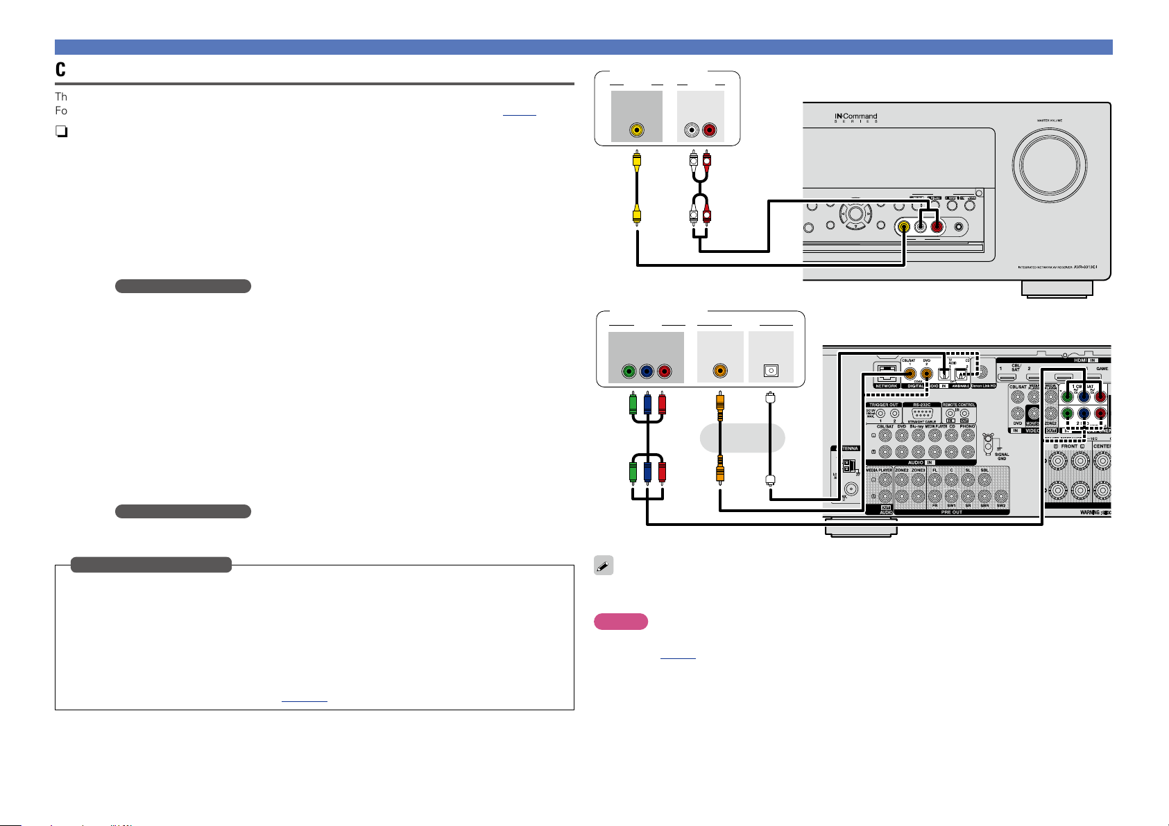
Connecting a Blu-ray Disc player
Basic version
Advanced version
Informations
Basic version
DVD
This section describes how to connect when your Blu-ray disc player does not support HDMI connections.
For instructions on HDMI connections, see “Connecting an HDMI-compatible device” (vpage8).
n Audio connection
The following methods are available for connecting to this unit. Use either of the methods to make
a connection.
The numbers prefixed with connectors indicate the recommendation order. The smaller the number is,
the higher playback quality is achieved.
a DIGITAL AUDIO COAXIAL connector
DIGITAL AUDIO OPTICAL connector
When a multichannel audio (digital bit stream audio) is input, this unit decodes the audio to play
back surround sound. However, digital bit stream audio signals for HD audios from Blu-ray disc
players (such as Dolby Digital Plus and dts-HD) can not be transmitted.
When making this type of connection, you must change the settings on this unit.
(v Input connector setting )
s AUDIO IN (Blu-ray) connector
This makes an analog audio connection. This type of connection converts digital audio to analog
audio, so the output audio may be degraded compared to connections a.
n Video connection
The following methods are available for connecting to this unit.
a COMPONENT VIDEO IN connector
This makes an analog video connection. This connection method separates video signals into 3
signals for transmission based on color components, achieving the best quality video playback
among analog video connections, with less signal degradation.
When making this type of connection, you must change the settings on this unit.
(v Input connector setting )
Blu-ray Disc player
AUDIO
OUT
L
COAXIAL
OUT
RL
R
a a as
or or
R
L
OPTICAL
OUT
VIDEOAUDIO
COMPONENT VIDEO
OUT
B PR
Y P
Connecting an HDMI-incompatible device
Input connector setting
When making the following connection, you must change the input connector settings.
a DIGITAL AUDIO COAXIAL connector
When connecting to connectors marked as 1, change “CBL/SAT” to “Blu-ray”.
DIGITAL AUDIO OPTICAL connector
When connecting to connectors marked as 1, change “TV AUDIO” to “Blu-ray”.
a COMPONENT VIDEO IN connector
When connecting to connectors marked as 1, change “CBL/SAT” to “Blu-ray”.
For how to change, see “Input Assign” (vpage125).
When you want to play back HD Audio (Dolby TrueHD, DTS-HD, Dolby Digital Plus, DTS Express) and Multichannel PCM with this unit, use an HDMI connection (vpage 8 “Connecting an HDMI-compatible
device”).
18
Page 22
Basic version
Advanced version
Informations
Basic version
DVD
Connecting a digital camcorder
This section describes how to connect when your digital camcorder does not support HDMI connections.
For instructions on HDMI connections, see “Connecting an HDMI-compatible device” (vpage8).
n Audio connection
The following methods are available for connecting to this unit. Use either of the methods to make
a connection.
The numbers prefixed with connectors indicate the recommendation order. The smaller the number is,
the higher playback quality is achieved.
a DIGITAL AUDIO COAXIAL connector
DIGITAL AUDIO OPTICAL connector
When a multichannel audio (digital bit stream audio) is input, this unit decodes the audio to play
back surround sound.
When making this type of connection, you must change the settings on this unit.
(v Input connector setting )
s AUDIO IN (AUX1) connector
This makes an analog audio connection. This type of connection converts digital audio to analog
audio, so the output audio may be degraded compared to connections a.
n Video connection
The following methods are available for connecting to this unit. Use either of the methods to make
a connection.
The numbers prefixed with connectors indicate the recommendation order. The smaller the number is,
the higher playback quality is achieved.
a COMPONENT VIDEO IN connector
This makes an analog video connection. This connection method separates video signals into 3
signals for transmission based on color components, achieving the best quality video playback
among analog video connections, with less signal degradation.
When making this type of connection, you must change the settings on this unit.
(v Input connector setting )
s VIDEO IN (AUX2) connector
This makes an analog video connection.
Input connector setting
When making the following connection, you must change the input connector settings.
a DIGITAL AUDIO COAXIAL connector
When connecting to connectors marked as 1, change “CBL/SAT” to “AUX2”.
DIGITAL AUDIO OPTICAL connector
When connecting to connectors marked as 1, change “TV AUDIO” to “AUX2”.
a COMPONENT VIDEO IN connector
When connecting to connectors marked as 1, change “CBL/SAT” to “AUX2”.
For how to change, see “Input Assign” (vpage125).
Connecting an HDMI-incompatible device
Digital camcorder
VIDEO
OUT
Digital camcorder
VIDEO AUDIO
COMPONENT VIDEO
OUT
B PR
Y P
AUDIOVIDEO
AUDIO
OUT
RL
R
L
ss
R
L
COAXIAL
OUT
OPTICAL
OUT
GFront panelH
INFO OPTION
STATUS DIMMER
PHONES
ENTER
BACK SETUP
GRear panelH
CBL/SAT
VIDEO AUDIOL - - R
AUX 1
QUICK SELECT
Blu-ray
NETWORK
GAME
SETUP MIC
aaa
or
You can enjoy games by connecting a game machine via the AUX1 input connector. In this case, select
the input source to “AUX1”.
NOTE
When a non-standard video signal from a game machine or some other source is input, the video conversion
function (vpage 6) might not operate. In this case, use the monitor output of the same connector
as the input.
19
Page 23
Connecting an HDMI-incompatible device
Basic version
Advanced version
Informations
Basic version
DVD
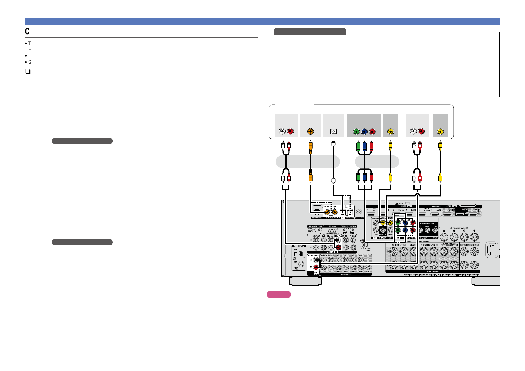
Connecting a media player
•This section describes how to connect when your media player does not support HDMI connections.
For instructions on HDMI connections, see “Connecting an HDMI-compatible device” (vpage8).
•When recording analog audio, use the analog connection.
•See “REC OUT mode” (vpage99) for operating instructions.
n Audio connection
The following methods are available for connecting to this unit. Use either of the methods to make
a connection.
The numbers prefixed with connectors indicate the recommendation order. The smaller the number is,
the higher playback quality is achieved.
a DIGITAL AUDIO COAXIAL connector
DIGITAL AUDIO OPTICAL connector
When a multichannel audio (digital bit stream audio) is input, this unit decodes the audio to play
back surround sound.
When making this type of connection, you must change the settings on this unit.
(v Input connector setting )
s AUDIO IN/OUT (MEDIA PLAYER) connector
This makes an analog audio connection. This type of connection converts digital audio to analog
audio, so the output audio may be degraded compared to connections a.
n Video connection
The following methods are available for connecting to this unit. Use either of the methods to make
a connection.
The numbers prefixed with connectors indicate the recommendation order. The smaller the number is,
the higher playback quality is achieved.
a COMPONENT VIDEO IN connector
This makes an analog video connection. This connection method separates video signals into 3
signals for transmission based on color components, achieving the best quality video playback
among analog video connections, with less signal degradation.
When making this type of connection, you must change the settings on this unit.
(v Input connector setting )
s VIDEO IN/OUT (MEDIA PLAYER) connector
This makes an analog video connection.
Input connector setting
When making the following connection, you must change the input connector settings.
a DIGITAL AUDIO COAXIAL connector
When connecting to connectors marked as 1, change “CBL/SAT” to “MEDIA PLAYER”.
DIGITAL AUDIO OPTICAL connector
When connecting to connectors marked as 1, change “TV AUDIO” to “MEDIA PLAYER”.
a COMPONENT VIDEO IN connector
When connecting to connectors marked as 1, change “CBL/SAT” to “MEDIA PLAYER”.
For how to change, see “Input Assign” (vpage125).
Media player
AUDIO
OUT
L
COAXIAL
OUT
RL
R
a a a s ss s
OPTICAL
OUT
or or or
R
L
VIDEO VIDEOAUDIO AUDIO
COMPONENT VIDEO
OUT
B PR
Y P
VIDEO
OUT
AUDIO
IN
L
L
VIDEO
RL
R
R
IN
NOTE
To record video signals through this unit, use the video cable for connection between this unit and the
player.
20
Page 24
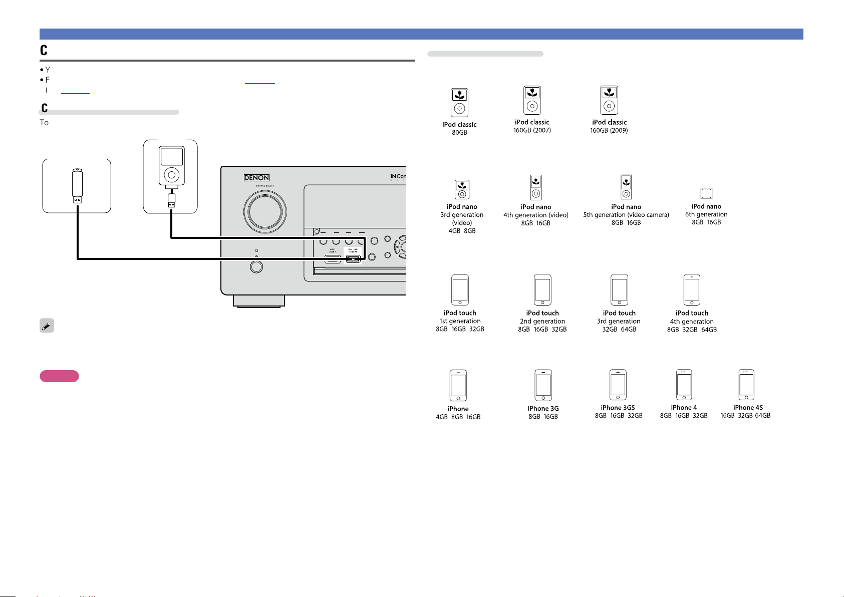
Connecting an iPod or USB memory device to the iPod/USB port
ENTER
Basic version
Advanced version
Informations
Basic version
DVD
Connecting an HDMI-incompatible device
Supported iPod models
•You can enjoy music stored on an iPod or USB memory device.
•For operating instructions see “Playing an iPod” (vpage 39) or “Playing a USB memory device”
(vpage42).
Cables used for connections
To connect an iPod to this unit, use the USB cable supplied with the iPod.
iPod
USB memory
device
or
ZONE 2
ZONE 3
SOURCE SELECT
REC SOURCE
SOURCE SELECT
ON/OFF ON/OFF
DENON does not guarantee that all USB memory devices will operate or receive power. When using a
portable USB connection type HDD of the kind to which an AC adapter can be connected to supply power,
use the AC adapter.
NOTE
•USB memory devices will not work via a USB hub.
•It is not possible to use this unit by connecting the unit’s iPod/USB port to a PC via a USB cable.
•Do not use an extension cable when connecting a USB memory device. This may cause radio interference
with other devices.
•When connecting an iPhone to this unit, keep the iPhone at least 20 cm away from this unit. If the iPhone
is kept closer to this unit and a telephone call is received by the iPhone, noise may be output from this
device.
•If the iPod is connected using an iPod cable (commercially available) that is longer than 6.6 ft (2 m), sound
may not be played correctly. In this case, use a genuine iPod cable, or a cable that is shorter than 3.3 ft
(1 m).
INFO
STATUS
PHONES
BACK
•iPod classic
•iPod nano
•iPod touch
•iPhone
(as of April 2012)
21
Page 25
Connecting an HDMI-incompatible device
Basic version
Advanced version
Informations
Basic version
DVD
Connecting a CD player
You can enjoy CD sound.
n Audio connection
The following methods are available for connecting to this unit. Use either of the methods to make
a connection.
The numbers prefixed with connectors indicate the recommendation order. The smaller the number is,
the higher playback quality is achieved.
a DIGITAL AUDIO COAXIAL connector
DIGITAL AUDIO OPTICAL connector
When a multichannel audio (digital bit stream audio) is input, this unit decodes the audio to play
back surround sound.
z When making this type of connection, you must change the settings on this unit.
(v Input connector setting )
s AUDIO IN (CD) connector
This makes an analog audio connection. This type of connection converts digital audio to analog
audio, so the output audio may be degraded compared to connections a.
Input connector setting
When making the following connection, you must change the input connector settings.
a DIGITAL AUDIO COAXIAL connector
When connecting to connectors marked as 1, change “CBL/SAT” to “CD”.
For how to change, see “Input Assign” (vpage125).
z
CD player
AUDIO
OUT
RL
R
L
R
L
AUDIO
COAXIAL
OUT
a as
or or
OPTICAL
OUT
When you want to play back HD Audio (Dolby TrueHD, DTS-HD, Dolby Digital Plus, DTS Express), DSD
and Multi-channel PCM with this unit, use an HDMI connection (vpage 8 “Connecting an HDMIcompatible device”).
22
Page 26
Connecting an HDMI-incompatible device
Basic version
Advanced version
Informations
Basic version
DVD
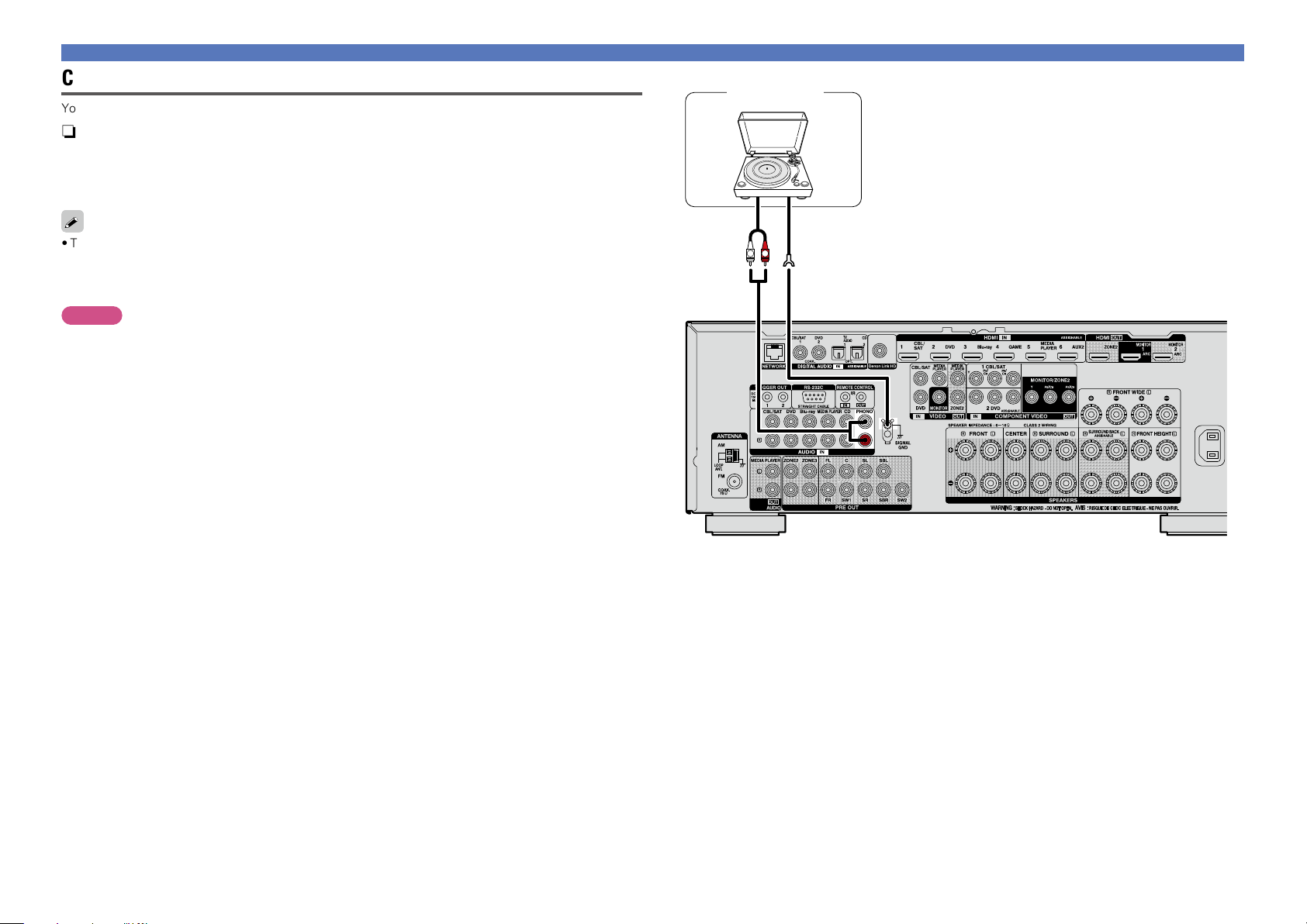
Connecting a record player
You can enjoy playing records.
n Audio connection
The following methods are available for connecting to this unit.
a AUDIO IN (PHONO) connector
This makes an analog audio connection.
•This unit is compatible with record players with an MM cartridge. When you connect to a record player
with an MC cartridge, use a commercially available MC head amp or a step-up transformer.
•If you set this unit’s input source to “PHONO” and increase the volume without connecting the record
player, there may be a “booming” noise from the speakers.
NOTE
The SIGNAL GND terminal of this unit is not a safety ground connection. Connect it to reduce noise when
noise is excessive. Note that depending on the record player, connecting the ground line may have the
reverse effect of increasing noise. In this case, it is not necessary to connect the ground line.
Turntable
(MM cartridge)
AUDIO
OUT
R
L
GND
23
Page 27

Connecting an HDRadio receiver
Basic version
Advanced version
Informations
Basic version
DVD
•By connecting a HDRadio antenna to this unit, you can receive HDRadio programs.
•HDRadio broadcasting currentry is available in the United States and select other countries.
•After connecting the antenna and receiving a broadcast signal (vpage46 “Listening to HD Radio
stations”), fix the antenna with tape in a position where the noise level becomes minimal.
n AM loop antenna assembly
Direction of broadcasting station
FM outdoor
antenna
Connecting an HDMI-incompatible device
AM loop antenna (for HDRadio
broadcasting, supplied)
•To prevent interference, install at least 3.3
ft/1 m away from the antenna connected
to the this unit’s other AM tuner terminal.
Put the stand section through the bottom of the
1
loop antenna from the rear and bend it forward.
Insert the projecting part into the square hole in
2
the stand.
Loop
antenna
Stand
Square
hole
Projecting
part
n Using the AM loop antenna
Suspending on a wall
Suspend directly on a wall without assembling.
Nail, tack, etc.
NOTE
•Do not connect two FM antennas simultaneously.
•Even if an external AM antenna is used, do not disconnect the AM loop antenna.
•Make sure the AM loop antenna lead terminals do not touch metal parts of the panel.
•If the signal has noise interference, connect the ground terminal (GND) to reduce noise.
•If you are unable to receive a good broadcast signal, we recommend installing an outdoor antenna. For
details, inquire at the retail store where you purchased the unit.
Standing alone
Use the procedure shown above to assemble.
75 Ω coaxial
cable
FM indoor antenna
(for HDRadio
broadcasting, supplied)
White
Black
w eq
Ground
AM outdoor
antenna
24
Page 28
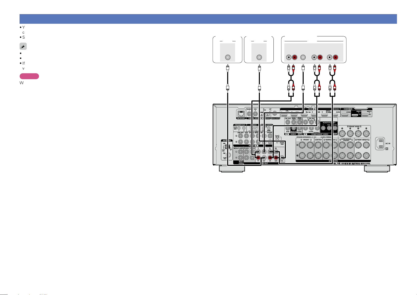
Connecting a external power amplifier
Basic version
Advanced version
Informations
Basic version
DVD
•You can use this unit as a pre-amp by connecting a commercially available power amp to the PRE OUT
connector. Adding a power amp to each of the channels provides an even greater sound presence.
•Select the terminal to use and connect the device.
•When using just one surround back speaker, connect it to the left channel (L) terminal.
•Use the volume control on the subwoofer to control subwoofer volume.
•If the subwoofer volume sounds low, use the volume control provided on the subwoofer to adjust the
volume.
NOTE
When external power amplifier have been connected to PRE OUT terminals, do not connect the speakers
to the speaker terminals.
Subwoofer
(Primary)
AUDIO
SUB-
WOOFER
1
Subwoofer
(Secondary)
AUDIO
SUB-
WOOFER
2
Power amplifier
AUDIO
CENTER SURROUND
FRONT
RL
R R R
L
L
SURROUND
L
L
BACK
RL
L
RR R
L
RL
25
Page 29
Connecting an external control device
Basic version
Advanced version
Informations
Basic version
DVD
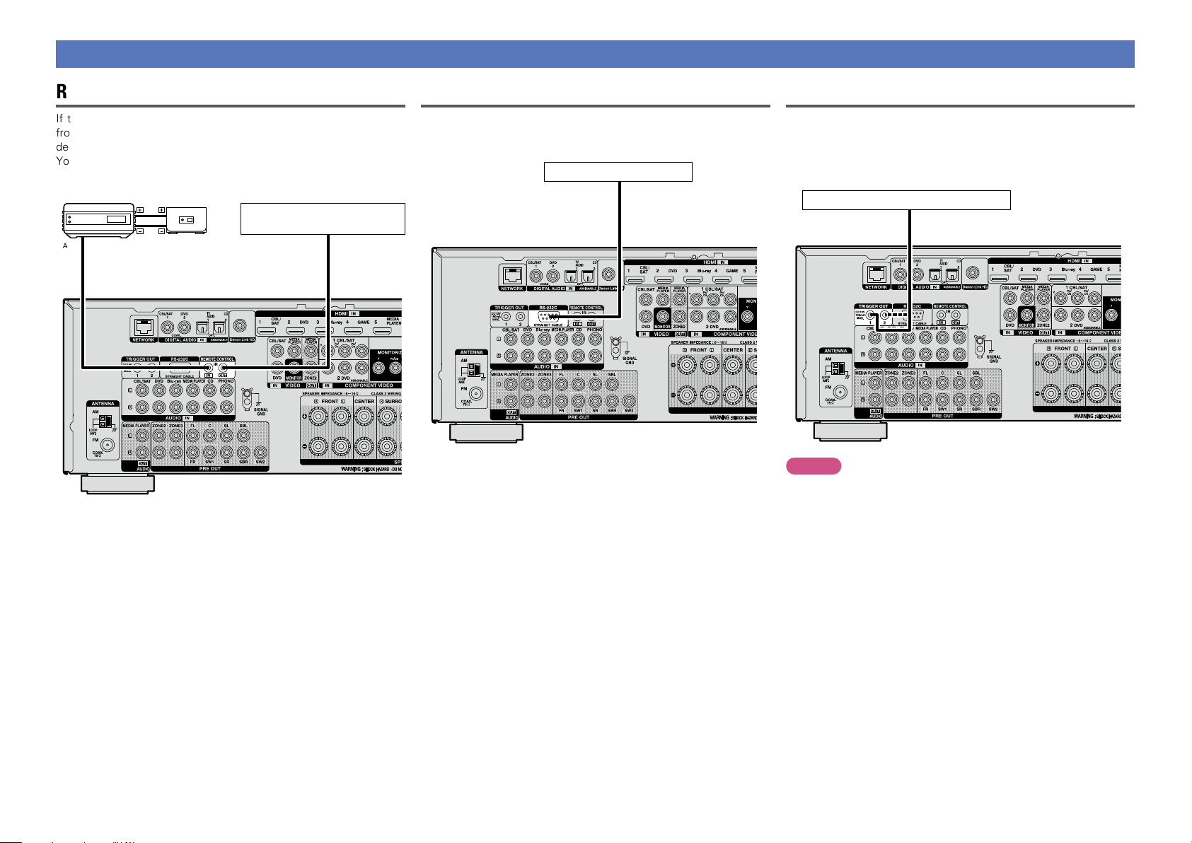
REMOTE CONTROL jacks
If this unit is installed in a location that is out of range of the signal
from the remote control unit, you can still operate the unit and the
devices connected to it by using a commercially available IR receiver.
You can also use it to remotely control ZONE2, ZONE3 (another room).
retransmitter
AUX
OUT
Infrared
Input
Infrared
sensor
Device equipped with a
REMOTE CONTROL IN jack
Output
RS-232C connector
When you connect an external control device, you can control this
unit with the external control device (such as power supply operation,
volume adjustment, and input source switching).
External serial controller
Perform the operation below beforehand.
q Turn on the power of this unit.
w Turn off the power of this unit from the external controller.
e Check that the unit is in the standby mode.
TRIGGER OUT jacks
When a device with TRIGGER IN jack is connected, the connected
device’s power on/standby can be controlled through linked operation
to this unit.
The TRIGGER OUT jack outputs a maximum 12 V/150 mA electrical
signal.
12 V/150 mA trigger-compatible device
NOTE
•Use the monaural mini-plug cable for connecting TRIGGER OUT
jacks. Do not use the stereo mini-plug cable.
•If the permissible trigger input level for the connected device is larger
than 12 V/150 mA, or has shorted, the TRIGGER OUT jack cannot be
used. In this case, turn off the power to the unit, and disconnect it.
26
Page 30
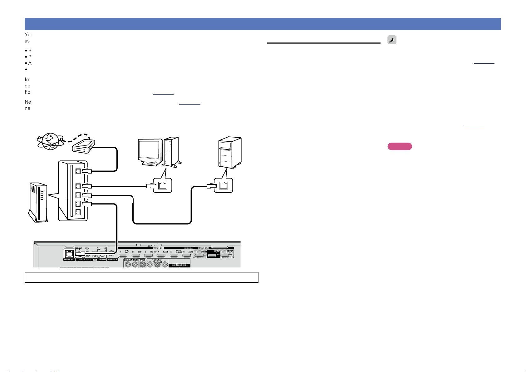
Connecting to a home network (LAN)
Basic version
Advanced version
Informations
Basic version
DVD
You can connect this unit to your home network (LAN) to perform various types of playbacks and operations
as follows. Make network connections for this unit by carefully reading information on this page.
•Playback of network audio such as the Internet radio and music servers
•Playback of music from online services
•AirPlay
•Operations on this unit via the network
In addition, when an updated firmware becomes available for improving this unit, the update information is
delivered from us to this unit over the network. You can then download the latest firmware.
For more information, on the menu, select “Update” (vpage143).
Network settings are necessary. See “Network” on the menu (vpage 135) for more information on
network setting.
NAS
(Network Attached
PC
Modem
Internet
To WAN side
To LAN port
To LAN port
Router
For connections to the Internet, contact an ISP (Internet Service Provider) or a computer shop.
LAN port/
Ethernet
connector
Storage)
LAN port/
Ethernet
connector
Required system
n Broadband internet connection
n Modem
Device that connects to the broadband circuit
and conducts communications on the Internet.
A type that is integrated with a router is also
available.
n Router
When using this unit, we recommend you use
a router equipped with the following functions:
•Built-in DHCP server
This function automatically assigns IP
addresses on the LAN.
•Built-in 100BASE-TX switch
When connecting multiple devices, we
recommend a switching hub with a speed of
100 Mbps or greater.
n Ethernet cable
(CAT-5 or greater recommended)
•Use only a shielded STP or ScTP LAN cable
which is available at retailer.
•The normal shielded-type Ethernet cable
is recommended. If a flat-type cable or
unshielded-type cable is used, other devices
could be affected by noise.
•If you have an Internet provider contract for a line
on which network settings are made manually,
make the settings at “Network” (vpage135).
•With this unit, it is possible to use the DHCP and
Auto IP functions to make the network settings
automatically.
•When using this unit with the broadband router’s
DHCP function enabled, this unit automatically
performs the IP address setting and other
settings.
When using this unit connected to a network with
no DHCP function, make the settings for the IP
address, etc., at “Network” (vpage135).
•When setting manually, check the setting
contents with the network administrator.
NOTE
•A contract with an ISP is required to connect to
the Internet.
No additional contract is needed if you already
have a broadband connection to the Internet.
•The types of routers that can be used depend on
the ISP. Contact an ISP or a computer shop for
details.
•DENON assumes no responsibility whatsoever
for any communication errors or troubles
resulting from customer’s network environment
or connected devices.
•This unit is not compatible with PPPoE. A PPPoEcompatible router is required if you have a contract
for a type of line set by PPPoE.
•Do not connect an NETWORK connector directly
to the LAN port/ Ethernet connector on your
computer.
•To listen to audio streaming, use a router that
supports audio streaming.
27
Page 31

Connecting the power cord
Basic version
Advanced version
Informations
Basic version
DVD
After completing all the connections, insert the power plug into the power outlet.
To household power outlet
(AC 120 V, 60 Hz)
NOTE
•Do not plug in the power cord until all connections have been completed.
•Do not bundle power cords together with connection cables. Doing so can result in humming or noise.
Power cord (supplied)
28
Page 32

Setup
Basic version
Advanced version
Informations
Basic version
v See overleaf
DVD
Here, we explain “Audyssey® Setup”, which allows you to
automatically make the optimal settings for your speakers, and
“Network”, which allows you to connect this unit to a home network
(LAN).
This unit lets you play via your home network (LAN) music files stored
on a computer and music content such as that from Internet radio.
n Speaker connection (vpage84)
n Set up speakers (Audyssey® Setup) (vpage29)
n Making the network settings (Network)
(vpage35)
Playback (Basic operation) (vpage36)
Selecting a listening mode (Sound Mode)
(vpage75)
Playback (Advanced operation) (vpage95)
Set up speakers (Audyssey® Setup)
The acoustic characteristics of the connected speakers and
listening room are measured and the optimum settings are made
automatically. This is called “Audyssey® Setup”.
To perform measurement, place the setup microphone in
multiple locations all around the listening area. For best results,
we recommend you measure in six or more positions, as shown
in the illustration (up to eight positions).
•When performing Audyssey® Setup, Audyssey MultEQ® XT/
Audyssey Dynamic EQ®/Audyssey Dynamic Volume® functions
become active (vpage116).
•To set up the speakers manually, use “Speakers” (vpage129)
on the menu.
NOTE
•Make the room as quiet as possible. Background noise can disrupt
the room measurements. Close windows and turn off the power on
electronic devices (TVs, radios, air conditioners, fluorescent lights,
etc.). The measurements could be affected by the sounds emitted
by such devices.
•During the measurement process, place cell phones outside the
listening room. Cell phone signals could disrupt the measurements.
•Do not unplug the setup microphone from the main unit until
Audyssey® Setup is completed.
•Do not stand between the speakers and setup microphone or allow
obstacles in the path while the measurements are being made. This
will cause inaccurate readings.
•During the measurement process, loud test sounds may be played,
but this is part of normal operation. If there is background noise in
room, these test signals will increase in volume.
•Operating
control unit or MASTER VOLUME on the
main unit during the measurements will
cancel the measurements.
•Measurement cannot be performed when headphones are
connected. Unplug the headphones before performing Audyssey®
Setup.
VOLUME df on the remote
About setup microphone placement
•Measurements are performed by placing the setup microphone
successively at multiple positions throughout the entire listening
area, as shown in GExample qH. For best results, we recommend
you measure in six or more positions, as shown in the illustration (up
to eight positions).
•Even if the listening environment is small as shown in GExample wH,
measuring at multiple points throughout the listening environment
results in more effective correction.
GExample qH GExample wH
FL SW C FR
( : Measuring positions)
M
*
FL Front speaker (L) SW Subwoofer
FR Front speaker (R) SL Surround speaker (L)
C Center speaker SR Surround speaker (R)
SRSL
FL SW C FR
( : Measuring positions)
M
*
SRSL
About the main listening position (*M)
The main listening position is the position where listeners would
normally sit or where one would normally sit alone within the listening
environment. Before starting Audyssey® Setup, place the setup
microphone in the main listening position. Audyssey MultEQ® XT uses
the measurements from this position to calculate speaker distance,
level, polarity, and the optimum crossover value for the subwoofer.
29
Page 33

Set up speakers (Audyssey® Setup)
Basic version
Advanced version
Informations
Basic version
v See overleaf
DVD
1
Prepare the included setup microphone
Mount the setup microphone on a tripod or stand
and place it in the main listening position.
When placing the setup microphone, adjust the height of the
sound receptor to the level of the listener’s ear.
Sound receptor
Setup microphone
If you do not have a tripod or stand, set up the microphone on, for
example, a seat without a back.
NOTE
•Do not hold the setup microphone in your hand during
measurements.
•Avoid placing the setup microphone close to a seat back or wall as
sound reflections may give inaccurate results.
2
Set up the subwoofer
If using a subwoofer capable of the following
adjustments, set up the subwoofer as shown below.
For details, see your subwoofer’s manual.
n When using a subwoofer with a direct mode
Set the direct mode to “On” and disable the volume adjustment
and crossover frequency setting.
n When using a subwoofer without a direct mode
Make the following settings:
•Volume : “12 o’clock position”
•Crossover frequency : “Maximum/Highest Frequency”
•Low pass filter : “Off”
•Standby mode : “Off”
NOTE
When using 2 subwoofers at the same time, before starting
Audyssey® Setup. adjust the volume of the subwoofers by using
“Subwoofer Level” (vpage115) from the menu. You cannot set
the volume for individual subwoofers.
3
Set up the remote control unit
n Set up the zone mode
Press MAIN to switch the zone mode to the MAIN
ZONE.
MAIN lights.
Preparation
Connect the setup microphone to the SETUP MIC
4
jack of this unit.
When the setup microphone is
connected, the following screen is
displayed.
Audyssey Setup
Your AV receiver can automatically measure the acoustics of
your room then optimize your speakers using the included
microphone.
Set the following items
if necessary.
Amp Assign
Channel Select
Start
•Here, we explain setup using the example of 5.1-channel speaker
playback.
For settings other than 5.1-channel speaker playback, select
“Amp Assign” and perform step 3 to 6 of “Set up “Amp Assign””
(vpage92).
If unused channels are set with “Channel Select”, measuring time
can be shortened. For setting, perform steps 7 to 14 of “Set up
“Channel Select”” (vpage93).
Press MAIN
NOTE
When using a remote control with preset codes registered
(vpage 148), press AVR to set the remote control to the AVRoperation mode before operation.
30
Page 34

Set up speakers (Audyssey® Setup)
Basic version
Advanced version
Informations
Basic version
v See overleaf
DVD
Preparation (Continued)
Select “Start” and then press
5
ENTER.
Audyssey Setup
Connect the calibration microphone to the SETUP MIC input
on the front the AV receiver.
Back Next
Select “Next” and then press ENTER.
6
The subwoofer volume setting screen is displayed.
Audyssey Setup
If your subwoofer has a volume control on it, please set it
at 50%...
VOLUME
MIN
MAX
Back Next
Detection & Measurement (Main)
•This step automatically checks the speaker configuration and speaker
size, and calculates the channel level, distance, and crossover
frequency.
It also corrects distortion in the listening area.
Select “Begin Test” and then press ENTER.
7
When measuring begins, a test tone is output from each
speaker.
•Measurement requires several minutes.
The detected speakers are displayed.
8
•The illustration below shows an example of when the front
speakers, center speaker, subwoofer and surround speakers have
been detected.
Audyssey Setup
Speaker Detection
Front
Center
Subwoofer
Surround
Surr. Back
Front Height
Front Wide
Repeat Last Test Next
NOTE
If a connected speaker is not displayed, the speaker may not be
connected correctly. Check the speaker connection.
:Yes
:Yes
:Yes
:Yes
:None
:None
:None
NOTE
If “Caution!” is displayed on TV screen:
Go to “Error messages” (vpage 34). Check any related items,
and perform the necessary procedures.
If the problem is resolved, return and restart “Audyssey® Setup”.
Going back to the previous screen
Select “Back” and then press ENTER.
When measuring has stopped
q Press BACK to display the popup screen.
w Press o to select “Yes”, and then press ENTER.
Setting up the speakers again
Repeat the operation from step 4.
Select “Next” and then press ENTER.
9
31
Page 35

Set up speakers (Audyssey® Setup)
Basic version
Advanced version
Informations
Basic version
v See overleaf
DVD
Measurement (2nd – 8th)
•In this step, you will perform measurements at multiple positions
(two to eight positions) other than the main listening position.
•Just one position can be measured but measuring multiple positions
increases the accuracy of the correction of acoustic distortion within
the listening area.
Move the setup microphone to
10
position 2, select “Continue”,
and then press ENTER.
The measurement of the second
position starts. Measurements can be
made in up to eight positions.
Audyssey Setup
Place the microphone at ear level at the 2nd listening position,
then select “Continue”...
Continue
Calculation
Audyssey Setup
Place the microphone at ear level at the 3rd listening position,
then select “Continue”...
Repeat step 10, measuring positions 3 to 8.
When measurement of position 8 is completed, a
11
“Measurements finished.” message is displayed.
Audyssey Setup
Measurements finished.
Calculation
Repeat Last Test
Calculation
Select “Calculation” and then press ENTER.
12
Measuring results are analyzed, and the frequency response of
each speaker in the listening room is determined.
Audyssey Setup
Calibration completed! Now calculating...Please wait.
50%
•Analysis takes several minutes to complete. The more speakers
and measurement positions that there are, the more time it takes
to perform the analysis.
•To skip measuring the third and subsequent listening position, use
ui to select “Calculation” and press ENTER to proceed to step
13.
•To measure the second position again, use ui to select “Repeat
Last Test” and press ENTER.
Continue
Calculation
Repeat Last Test
32
Page 36

Set up speakers (Audyssey® Setup)
Basic version
Advanced version
Informations
Basic version
DVD
Store FinishCheck
Use ui to select the item you
13
want to check, and then press
ENTER.
Audyssey Setup
Check processing results. To proceed, press “Store”.
Speaker Config.
Distances
Levels
Crossovers
Store
•Subwoofers may measure a greater reported distance than
the actual distance due to added electrical delay common in
subwoofers.
•If you want to check another item, press BACK.
NOTE
•If the result differs from the actual connection status, or if “Caution!”
is displayed, see “Error messages” (vpage 34). Then carry out
Audyssey® Setup again.
• If you change speaker positions or orientation, perform Audyssey®
Setup again to find the optimal equalizer settings.
Select “Store” and then press ENTER.
14
Save the measurement results.
Audyssey Setup
Check processing results. To proceed, press “Store”.
Speaker Config.
Distances
Levels
Crossovers
Store
Audyssey Setup
Now storing...Please wait.
50%
•Saving the results requires about 10 seconds.
•During saving of measurements results, “Now storing...Please
wait.” is displayed. When saving is completed, “Storing complete.
Audyssey® Setup is now finished. Please unplug microphone.” is
displayed.
NOTE
During saving of measurement results, be sure not to turn off the
power.
Unplug the setup microphone from the unit’s SETUP
15
MIC jack.
Set Audyssey Dynamic Volume.
16
Audyssey Setup
You can set Dynamic Volume function, which automatically
adjusts volume level for all content.
Do you want to enable?
Yes
No
•This feature adjusts the output volume to the optimal level while
constantly monitoring the level of the audio input to the unit.
Optimal volume control is performed automatically without any
loss in the dynamism and clarity of the sound when, for example,
the volume suddenly increases for commercials shown during
television programs.
n When turning Dynamic Volume on
•Press u to select “Yes”, and then press ENTER.
The unit automatically enters “Medium” (vpage117) mode.
n When turning Dynamic Volume off
•Press i to select “No”, and then press ENTER.
NOTE
After performing Audyssey® Setup, do not change the speaker
connections or subwoofer volume. In event of a change, perform
Audyssey® Setup again.
33
Page 37

Set up speakers (Audyssey® Setup)
Basic version
Advanced version
Informations
Basic version
DVD
Error messages
NOTE
•An error message is displayed if Audyssey® Setup could not be completed due to speaker placement, the measurement environment, etc. If an error message is displayed, check the relevant items and perform the
necessary measures. Then perform Audyssey® Setup again.
•If the result still differs from the actual connection status after remeasurement or the error message still appears, it is possible that the speakers are not connected properly. Turn this unit off, check the speaker
connections and repeat the measurement process from the beginning.
•Be sure to turn off the power before checking speaker connections.
Examples Error details Measures
Audyssey Setup
Caution! : Please check the cable connection and retry.
Microphone or Speaker is none
Retry
•The connected setup microphone is broken, or a device other than the
supplied setup microphone is connected.
•Not all speakers could be detected.
•Connect the included setup microphone to the SETUP MIC jack of this unit.
•Check the speaker connections.
Audyssey Setup
Caution!
Ambient noise is too high or level is too low
Retry
Audyssey Setup
Caution! : Please check the cable connection and retry.
Front R :None
Retry
Audyssey Setup
Caution! : Please check the cable connection and retry.
Front R :Phase
Retry Skip ErrorPhase Info.
•There is too much noise in the room for accurate measurements to be
made.
•Speaker or subwoofer sound is too low for accurate measurements to be
made.
•The displayed speaker could not be detected.
(The screen on the left indicates that the front right speaker cannot be
detected.)
•The displayed speaker is connected with the polarity reversed.
(The screen on the left indicates that the polarity phases of the front right
speakers are reversed.)
•Either turn off any device generating noise or move it away.
•Perform again when the surroundings are quieter.
•Check the speaker installation and the direction in which the speakers are
facing.
•Adjust the subwoofer’s volume.
•Check the connections of the displayed speaker.
•Check the polarity of the displayed speaker.
•For some speakers, this error message may be
displayed even if the speaker is properly connected.
If you are sure the connection is correct, use o p
to select “Skip Error”, then press ENTER.
34
Page 38

Set up speakers (Audyssey® Setup)
Basic version
Advanced version
Informations
Basic version
DVD
Parameter Check
This function enables you to check the measurement results and equalizer characteristics after Audyssey
Setup.
Use ui to select “Parameter Check” and then press ENTER.
1
Audyssey Setup
Your AV receiver can automatically measure the acoustics of
your room then optimize your speakers using the included
microphone.
Set the following items
if necessary.
Amp Assign
Channel Select
Parameter Check
Start
Use ui to select the item you want to check, then press ENTER.
2
Measurement results for each speaker are displayed.
Speaker Config.
Distances
Levels
Crossovers
Equalizers
Check the speaker configuration.
Check the speaker distance.
Check the speaker channel level.
Check the speaker crossover frequency.
Check the equalizer.
Audyssey Setup/Parameter Check
Check Audyssey Setup Measurement results.
Speaker Config.
Distances
Levels
Crossovers
Equalizers
Restore...
Making the network settings (Network)
®
This unit can be connected to a home network (LAN) to listen to Internet radio or play back music files and
still image (JPEG) files stored on a computer.
Connect the Ethernet cable (vpage 27 “Connecting to a home network (LAN)”).
1
Turn on this unit (vpage 36).
2
This unit performs automatic network setup due to the DHCP function.
When connecting to a network that has no DHCP function, perform the setting in “Settings”
(vpage137).
•If “Equalizers” is selected, press
be checked.
Use ui to switch the display between the different speakers.
ui to select equalizing curve (“Audyssey” or “Audyssey Flat”) to
Press o or BACK.
3
The confirmation screen reappears. Repeat step 2.
Retrieving Audyssey® Setup settings
If you set “Restore...” to “Yes”, you can return to Audyssey® Setup measurement result (value calculated
at the start by MultEQ® XT) even when you have changed each setting manually.
35
Page 39

Playback (Basic operation)
Basic version
Advanced version
Informations
Basic version
DVD
Setup (vpage29)
n Turning the power on (vpage36)
n Selecting the input source (vpage36)
n Adjusting the master volume (vpage37)
n Turning off the sound temporarily (vpage37)
n Playing a Blu-ray Disc player/DVD player
(vpage37)
n Playing a Blu-ray Disc player compatible with
Denon Link HD (vpage37)
n Playing Super Audio CD (vpage38)
n Playing a CD player (vpage38)
n Playing an iPod (vpage39)
n Playing a USB memory device (vpage42)
n Listening to HDRadio stations (vpage45)
n Listening to internet radio (vpage54)
n Playing back files stored on a PC and NAS
(vpage57)
n Using online services (vpage61)
n Convenient functions (vpage69)
n AirPlay function (vpage73)
Important information
Before starting playback, make the connections between the different
devices and the settings on the unit.
NOTE
Also refer to the operating instructions of the connected devices
when playing them.
Turning the power on
Press POWER X to turn on power to
the unit.
The power indicator flashes green and the
power turns on.
You can also switch the power to standby by pressing X on the main
unit.
n When power is switched to standby
Press POWER X.
GPower indicator status in standby modeH
•Normal standby : Off
•When “HDMI Control” (vpage121) is set to “On” : Red
•When “IP Control” (vpage136) is set to “Always On” : Red
Selecting the input source
Press the input source select button
(CBL/SAT, DVD, Blu-ray, AUX1,
TV AUDIO, TUNER, GAME, AUX2,
PHONO, iPod/USB, MEDIA PLAYER,
CD, NETWORK or INTERNET RADIO)
to be played back.
The desired input source can be selected
directly.
You can also use the following operation to select an input
source.
n Select the input source using the main unit
Turn SOURCE SELECT.
•Turning SOURCE SELECT switches the input source, as shown
below.
Blu-rayDVDCBL/SAT
PHONO
GAME AUX1 AUX2
MEDIA
PLAYER
iPod/USBHD RadioNETWORK CDTV AUDIO
Selecting a listening mode (Sound Mode)
(vpage75)
Playback (Advanced operation) (vpage95)
36
Page 40

Important information
Basic version
Advanced version
Informations
Basic version
DVD
Adjusting the master volume
Use VOLUME df to adjust the
volume.
•The volume display method varies
depending on the “Scale” setting
(vpage116).
n When the “Scale” setting
(vpage116) is “0 – 98”
0.0
0.5 – 98.0
– – –.–
–79.5dB – 18.0dB
GAdjustable rangeH
n When the “Scale” setting (vpage116) is “–79.5dB –
18.0dB”
GAdjustable rangeH
•The variable range differs according to the input signal and channel
level setting.
You can also adjust the master volume by turning MASTER VOLUME
on the main unit.
Turning off the sound temporarily
Press MUTE :.
•“MUTE” indicator on the display flashes.
•: appears on a TV screen.
Playing a Blu-ray Disc player/DVD player
The following describes the procedure for playing Blu-ray Disc player/
DVD player.
Prepare for playback.
q Turn on the power of the TV,
1
subwoofer and player.
w Change the TV input to the input of
this unit.
e Load the disc in the player.
Press POWER X to turn on power
2
to the unit.
Press Blu-ray or DVD to switch an input source for a
3
player used for playback.
Play the Blu-ray Disc player or DVD player.
4
•Make the necessary settings on the player (language setting,
subtitles setting, etc.) beforehand.
Playing a Blu-ray Disc player compatible with Denon Link HD
•Denon Link HD uses the clock of the AV amplifier connected by
Denon Link to achieve HDMI signal transfer with low jitter when
playing BD.
•To play Denon Link HD signals, make HDMI and Denon Link
connections with a compatible Blu-ray disc player (“Connecting a
player compatible with the Denon Link HD function” (vpage12).
Prepare for playback.
q Turn on the power of the TV,
1
2
3
subwoofer and player.
w Change the TV input to the input of
this unit.
e Load the disc in the player.
Press POWER X to turn on power
to the unit.
Perform the settings of the “Input Assign” menu
(vpage 125).
q Assign HDMI connectors for the input source.
(example: Blu-ray)
w Set “DIGITAL” to “D.LINK”.
Set “HDMI Control” (vpage 121) to “On”.
4
Press the input source select button (example: Blu-
5
ray) to switch an input source assigned in step 3 - q.
•The sound is reduced to the level set at “Mute Level” (vpage116).
•To cancel, press MUTE : again. Muting can also be canceled by
adjusting the master volume.
37
Set the audio input mode to “Auto” using the “Input
6
Mode” menu (vpage 127).
•The default setting of “Input Mode” is “Auto”.
Play the component connected to this unit.
7
•Make the necessary settings on the player (language setting,
subtitles setting, etc.) beforehand.
Page 41

Playing a Blu-ray Disc player compatible with Denon Link HD
Basic version
Advanced version
Informations
Basic version
DVD
NOTE
•Set the Blu-ray disc player’s “Denon Link” setting to “On”. For
instructions on operation, refer to the Blu-ray disc player’s manual.
•When a Blu-ray disc is played with the input mode set to “Auto”,
playback is performed in the Denon Link HD mode.
•When the input mode is set to “HDMI”, normal HDMI playback is
performed.
Playing Super Audio CD
The following describes the procedure for playing Super Audio CD.
Prepare for playback.
q Turn on the power of the subwoofer
1
and player.
w Load the disc in the player.
Press POWER X to turn on power
2
to the unit.
Perform the settings of the “Input Assign” menu
3
(vpage 125).
Assign HDMI connectors for the input source(example: DVD).
Press the input source select button (example: DVD)
4
to switch an input source assigned in step 3 - q.
Set the audio input mode to “Auto” using the “Input
5
Mode” menu (vpage 127).
•The default setting of “Input Mode” is “Auto”.
Play the component connected to this unit.
The indicator lights on the display.
6
Playing a CD player
The following describes the procedure for playing CD player.
Prepare for playback.
q Turn on the power of the subwoofer
1
2
3
and player.
w Load the disc in the player.
Press POWER X to turn on power
to the unit.
Press CD to switch the input
source to “CD”.
Play the CD player.
4
When playing back Super Audio CD, DSD signals are converted into
PCM signals which are then converted into analog signals.
38
Page 42

Playing an iPod
Basic version
Advanced version
Informations
Basic version
DVD
You can use the USB cable provided with the iPod to connect the iPod
with the unit’s iPod/USB port and enjoy music stored on the iPod.
For information on the iPod models that can be played back with this
unit, see “Connecting an iPod or USB memory device to the iPod/USB
port” (vpage21).
Listening to music on an iPod
The iPod display modes include “Remote Mode” and “Browse
Mode”.
By default, “Remote Mode”, where you directly operate iPod itself
while seeing the iPod screen, is set.
To change to “Browse Mode”, where you perform operations while
having the iPod information displayed on the TV screen, see “Setting
Browse mode (Operation Mode)” (vpage40).
Operations available through the OPTION button
Press the OPTION button to display a menu of functions that can be
used on the TV screen. Select the function you want to use from this
menu. You can easily find and use the desired function.
n Setting Browse mode (Operation Mode)
(vpage40)
Using the USB cable provided
1
with the iPod, connect the
iPod to the iPod/USB port
(vpage 21).
Press POWER X to turn on
2
power to the unit.
Press iPod/USB to switch the
3
input source to “iPod/USB”.
“Remote iPod” is displayed on the
display of this unit.
•Nothing is displayed on the TV screen.
Operate iPod itself directly while seeing the iPod
4
screen to play back music.
n Streaming music stored in iPhone, iPod touch,
or iPad directly to the unit (vpage73)
n Playing iTunes music with this unit
(vpage73)
n Performing repeat playback (Repeat)
(vpage41)
n Performing random playback (Random)
(vpage41)
39
Page 43

n Setting Browse mode (Operation Mode)
Basic version
Advanced version
Informations
Basic version
DVD
In this mode, various lists and screens during playback on iPod are
displayed on the TV screen.
This section describes the steps up to playing back tracks on iPod
in “Browse Mode”.
Press iPod/USB to switch the input source to “iPod/
1
USB”.
Press OPTION.
2
The option menu screen is displayed.
Select “Operation Mode”, then press ENTER.
3
The “Operation Mode” screen is displayed.
Option
Operation Mode
Use o p to select “Browse
4
Mode”, then press ENTER.
The iPod screen is displayed.
•English letters, numbers and certain symbols are displayed.
Incompatible characters are displayed as “.” (period).
•Operations available for “Browse Mode” and “Remote Mode” are
listed below.
Display mode
Playable
files
Active
buttons
Music file
Video file
Remote
control unit
(This unit)
iPod
Remote Mode Browse Mode
P P
z
P P
P
z Only the sound is played.
Use ui to select the item, then press ENTER or p to
5
select the le to be played.
Press ENTER, p or 1.
6
Playback starts.
Playing an iPod
n Adjusting the sound quality (Restorer)
Make this setting at “Restorer” (vpage115) in the menu.
You can use the “Restorer” function to restore to a state close
to the audio before compression while correcting the bass feel to
enjoy a richer playback experience. The default setting is “Mode
3 (Low)”.
n Changing the screen display duration
Make this setting at “Audio Display” (vpage123) in the menu.
The default setting is “30s”.
Press uio p while the display is off to return to the original
screen.
n Switching the screen display
In Browse mode, press STATUS on the main unit during playback.
The display switches between track title, artist name, and album
title etc. each time the button is pressed.
NOTE
•Depending on the type of iPod and the software version, some
functions may not operate.
•Note that DENON will accept no responsibility whatsoever for any
problems arising with the data on an iPod when using this unit in
conjunction with the iPod.
Operation Mode
Browse Mode
40
Page 44

n Performing repeat playback (Repeat)
Basic version
Advanced version
Informations
Basic version
DVD
Press OPTION while in Browse mode.
1
The option menu screen is displayed.
Use ui to select “Repeat”, then press ENTER.
2
iPod
Now Playing
Title
Artist
Album
00:06 100%
Use o p to select repeat playback mode.
Repeat
Random
Operation Mode
Previous OptionPause
NextBack
Option
OPTION
3
iPod
Now Playing
Repeat
Title
All
Artist
Album
00:06 100%
OPTION
Previous OptionPause
NextBack
n Performing random playback (Random)
Press OPTION while in Browse mode.
1
The option menu screen is displayed.
Use ui to select “Random”, then press ENTER.
2
iPod
Now Playing
Title
Artist
Album
00:06 100%
Use o p to select random playback mode.
Repeat
Random
Operation Mode
Previous OptionPause
NextBack
Option
OPTION
3
iPod
Now Playing
Random
Title
Off
Artist
Album
00:06 100%
OPTION
Previous OptionPause
NextBack
n iPod operation buttons
Operation buttons Function
CH/PAGE df
INFO
OPTION
uio p
ENTER
(Press and release)
ENTER
(Press and hold)
BACK Return
SETUP Setup menu
8 9
1
6 7
(Press and hold)
3
2
Playing an iPod
Page search
Display of information such as the
source name, volume, and sound mode
name
Browse / Remote mode switching /
Repeat playback /
Random playback
Cursor operation /
Auto search (cue, ui) /
Manual search (Press and hold, ui)
Enter
Stop
Auto search (cue)
Playback / Pause
Manual search
(fast-reverse/fast-forward)
Pause
Stop
•Each time o p is pressed, the setting is changed as shown below.
Off One
All
Off
Repeat playback mode is canceled.
One
A file being played is played repeatedly.
All
All files in the folder currently being played are played
repeatedly.
Press ENTER.
4
The display returns to the playback screen.
•Each time o p is pressed, the setting is changed as shown below.
Off On
Off
Disable random playback.
On
Enable random playback.
Press ENTER.
4
The display returns to the playback screen.
The random playback randomly selects a track to play back from all
tracks every time a track ends. Therefore, the same track may be
played back consecutively.
41
Page 45

Playing a USB memory device
Basic version
Advanced version
Informations
Basic version
DVD
Playing back music or still picture (JPEG) files recorded on a USB memory device.
Important information
•Only USB memory devices conforming to mass storage class and MTP (Media Transfer Protocol)
standards can be played on this unit.
•This unit is compatible with USB memory devices in “FAT16” or “FAT32” format.
•This unit is compatible with MP3 files conforming to “MPEG-1 Audio Layer-3” standards.
•File types that this unit can play back and specifications are shown below.
GSupported file typesH
Supported file types USB memory devices
z2
WMA (Windows Media Audio)
MP3 (MPEG-1 Audio Layer-3)
WAV
MPEG-4 AAC
FLAC (Free Lossless Audio Codec)
JPEG
z1 USB memory device
•This unit is compatible with MP3 ID3-Tag (Ver.2) standard.
•This unit can show the artwork that was embedded by using MP3 ID3-Tag Ver.2.3 or 2.4.
•This unit is compatible with WMA META tags.
•If the image size (pixels) of an album artwork exceeds 500 × 500 (WMA/MP3/WAV/FLAC) or 349 ×
349 (MPEG-4 AAC), then music may not be played back properly.
•WAV format Quantization bit length: 16 bits.
•FLAC format Quantization bit length: 16 or 24 bits.
z2 Copyright-protected files can be played on certain portable players compatible with MTP.
z3 Only files that are not protected by copyright can be played on this unit.
Content downloaded from pay sites on the Internet are copyright protected. Also, files encoded in
WMA format when ripped from a CD, etc. on a computer may be copyright protected, depending on
the computer’s settings.
P
P
P
z3
P
P
P
NOTE
File types that this unit does not support are not displayed.
z1
GCompatible formatsH
Sampling frequency Bit rate Extension
WMA (Windows Media Audio) 32/44.1/48 kHz 48 – 192 kbps .wma
MP3 (MPEG-1 Audio Layer-3) 32/44.1/48 kHz 32 – 320 kbps .mp3
WAV 32/44.1/48 kHz – .wav
.aac/
MPEG-4 AAC 32/44.1/48 kHz 16 – 320 kbps
FLAC (Free Lossless Audio Codec) 32/44.1/48/88.2/96 kHz – .flac
.m4a/
.mp4
n Maximum Number of Playable Files and Folder
The limits on the number of folders and files that can be displayed by this unit are as follows.
Media
Item
Memory capacity FAT16 : 2 GB, FAT32 : 2 TB
Number of folder directory levels
Number of folders 500
Number of files
z1 The limited number includes the root folder.
z2 The allowable number of files may differ according to the USB memory device capacity and the file
size.
z2
z1
USB memory devices
8 levels
5000
42
Page 46

Playing files stored on USB memory
Basic version
Advanced version
Informations
Basic version
DVD
devices
Connect the USB memory device to the iPod/USB
1
port (vpage 21).
Press iPod/USB to switch the
2
input source to “iPod/USB”.
USB [1/9]
D&M1
D&M2
D&M3
Music1
Music2
Music3
Music4
OPTION
Option
Use ui to select the search item
3
or folder, then press ENTER or p.
Use ui to select the le, then
4
press ENTER, p or 1.
Playback starts.
n Adjusting the sound quality (Restorer)
Make this setting at “Restorer” (vpage115) in the menu.
You can use the “Restorer” function to restore to a state close
to the audio before compression while correcting the bass feel to
enjoy a richer playback experience. The default setting is “Mode
3 (Low)”.
n Going back to the previous screen
Press o or BACK.
n Changing the screen display duration
Make this setting at “Audio Display” (vpage123) in the menu.
The default setting is “30s”.
Press uio p while the display is off to return to the original
screen.
•When an MP3 music file includes album art data, the album art can
be displayed while playing the file.
•If the USB memory device is divided into multiple partitions, only the
first partition is played back.
NOTE
•Note that DENON will accept no responsibility whatsoever for any
problems arising with the data on a USB memory device when using
this unit in conjunction with the USB memory device.
•USB memory devices will not work via a USB hub.
•DENON does not guarantee that all USB memory devices will
operate or be supplied power. When using a USB portable hard disk
that can draw power from an AC adapter, we recommend using the
AC adapter.
•It is not possible to connect and use a computer via the iPod/USB
port of this unit using a USB cable.
Playing a USB memory device
Operations available through the OPTION button
Press the OPTION button to display a menu of functions that can be
used on the TV screen. Select the function you want to use from this
menu. You can easily find and use the desired function.
n Searching content with keywords
(Text Search) (vpage69)
n Performing repeat playback (Repeat)
(vpage70)
n Performing random playback (Random)
(vpage70)
n Playing back music and a favorite picture at the
same time (Picture View) (vpage72)
n Playing back still images in sequential order
(Slideshow) (vpage72)
43
Page 47

Playing a USB memory device
Basic version
Advanced version
Informations
Basic version
DVD
n USB memory device operation buttons
Operation buttons Function
CH/PAGE df
Display of information such as the
INFO
OPTION
uio p
ENTER
(Press and release)
ENTER
(Press and hold)
BACK Return
SETUP Setup menu
8 9
1
3
2
source name, volume, and sound mode
Page search
name
Text Search /
Repeat playback /
Random playback /
Picture View /
Slideshow
Cursor operation /
Auto search (cue, ui)
Enter
Stop
Auto search (cue)
Playback / Pause
Pause
Stop
44
Page 48

Listening to HDRadio stations
Basic version
Advanced version
Informations
Basic version
DVD
For antenna connections, see “Connecting an HDRadio receiver” (vpage24).
Important information
n Using the HDRadio™ receiver
HDRadio stations offer higher sound quality than conventional FM/ AM broadcasts. It is also possible to
receive data services and select broadcasts from among up to eight multicast programs.
HDRadio Technology provides higher quality sound than conventional broadcasts and allows reception
of data services.
•Digital, CD-quality sound. HDRadio Technology enables local radio stations to broadcast a clean digital
signal. AM sounds like today’s FM and FM sounds like a CD.
•Program Service Data: Contributes to the superior user experience of HDRadio Technology. Presents
song name, artist, station IDs, and other relevant data streams.
•Adjacent to traditional main stations are extra local FM channels. These HD2/HD3 Channels provide
new, original music as well as deep cuts into traditional genre.
How to tune in
The modes for receiving FM broadcasts consists of “Auto” mode that automatically searches available
broadcast stations and “Manual” mode that lets you tune in using buttons to change the frequency. The
default setting is “Auto”. You can also use “Direct Tune” to tune in by entering the frequency directly.
In “Auto” mode, you cannot tune in to radio stations if the reception is not good. If this is the case, then
use the “Manual” mode or “Direct Tune” to tune in.
HDRadio Technology manufactured under license from iBiquity Digital Corporation. U.S. and Foreign
Patents. HD Radio™ and the HD, HDRadio, and “Arc” logos are proprietary trademarks of iBiquity
Digital Corp.
For detailed information on HDRadio Technology, please go to “www.hdradio.com/”.
45
Page 49

Listening to HDRadio stations
Basic version
Advanced version
Informations
Basic version
v See overleaf
DVD
Press TUNER to switch the input source to
1
“HD Radio”.
GTV ScreenH
HD Radio
STEREO
HD-AUTO
CH 1
TUNE+/-
Tune Preset Option
FM 87.50MHz
CH / OPTION
GDisplay of this unitH
Now Playing
Use o p to select “FM” or “AM”, then press ENTER.
4
GTV ScreenH
HD Radio
STEREO
HD-AUTO
CH 1
TUNE+/-
Tune Preset Option
Band
FM
FM 87.50MHz
CH / OPTION
GDisplay of this unitH
Band • FM –
Now Playing
Listening to HDRadio stations
n Changing the screen display duration
Make this setting at “Audio Display” (vpage123) in the menu.
The default setting is “30s”.
Press uio p while the display is off to return to the original
screen.
n Adding to the FAVORITE STATION button
(vpage71)
Operations available through the OPTION button
Press the OPTION button to display a menu of functions that can be
used on the TV screen. Select the function you want to use from this
menu. You can easily find and use the desired function.
n Tuning in by entering the radio frequency
(Direct Tune) (vpage48)
01 FM 87.50MHz
Press OPTION.
2
The option menu screen is displayed.
Use ui to select “Band”, then press ENTER.
3
The Band screen is displayed.
GTV ScreenH
HD Radio
CH 1
TUNE+/-
Tune Preset Option
FM 87.50MHz
CH / OPTION
GDisplay of this unitH
*OPTION
Band
Option
STEREO
Band
Direct Tune
Preset Memory
Tune Mode
Auto Preset Memory
Preset Name
Preset Skip
Now Playing
HD-AUTO
FM
When listening to an FM broadcast.
AM
When listening to an AM broadcast.
Press TUNE + or TUNE – to select the station you
5
want to hear.
Scanning is performed until it finds an available radio station.
When it finds a radio station, it stops the scan automatically
and tunes in.
•If the desired station cannot be tuned in with auto tuning, tune it in
manually.
•When tuning in stations manually, press and hold TUNE + or TUNE –
to change frequencies continuously.
n Tuning in to radio stations and presetting them
automatically (Auto Preset Memory) (vpage49)
n Changing the tuning mode (Tune Mode)
(vpage47)
n Presetting the current broadcast station
(Preset Memory) (vpage50)
n Specify a name for the preset broadcast station
(Preset Name) (vpage51)
n Skipping preset broadcast stations
(Preset Skip) (vpage52)
46
Page 50

n Changing the tuning mode (Tune Mode)
Basic version
Advanced version
Informations
Basic version
DVD
You can change the mode for tuning into FM/AM broadcasts.
Press TUNER to switch the input
1
source to “HD Radio”.
Press OPTION.
2
The option menu screen is displayed.
Use ui to select “Tune Mode”,
3
then press ENTER.
GTV ScreenH
HD Radio
CH 1
TUNE+/-
Tune Preset Option
FM 87.50MHz
CH / OPTION
GDisplay of this unitH
*OPTION
Tune Mode
Option
STEREO
Band
Direct Tune
Preset Memory
Tune Mode
Auto Preset Memory
Preset Name
Preset Skip
Now Playing
HD-AUTO
Use o p to select tuning mode, then press ENTER.
4
GTV ScreenH
HD Radio
STEREO
HD-AUTO
CH 1
TUNE+/-
Tune Preset Option
Auto
HD-Auto
Analog-
Auto
Manual
AnalogManual
When tuning in stations manually, press and hold TUNE + or TUNE–
to change frequencies continuously.
Automatically tune to the station.
Automatically tune to the HDRadio station.
Automatically tune to an analog station and analog
HDRadio station.
Manually tune to the station.
Manually tune to an analog station and analog HDRadio
station.
Tune Mode
Auto
FM 87.50MHz
CH / OPTION
GDisplay of this unitH
Mode
• Auto –
Now Playing
Listening to HDRadio stations
n Selecting audio programs
HDRadio Technology enables stations to broadcast multiple Audio
Program and data services on HD2 / HD3 / HD4 channels.
Select the tuning mode
1
(“HD-Auto”, “Auto” or
“Manual”).
Press TUNE + or TUNE – to tune
2
in the desired Multicast channel.
•If the station you are tuning in has multiple audio programs,“HD1”is
indicated on the display.
If it only has one audio program, “HD”is indicated.
•When the unit receives multicast channels, the multicast program
number (HD2) is displayed to the right of the station name.
NOTE
•This function is not available for AM HDRadio stations because they
cannot broadcast multicast channels.
•If digital audio data cannot be received after the station is selected,
or if the station signal is weak, the unit may not be able to receive
the multicast channels.
•If the station signal is weak, the digital audio of the multicast channel
may cut out.
n Changing the screen display duration
Make this setting at “Audio Display” (vpage123) in the menu.
The default setting is “30s”.
Press uio p while the display is off to return to the original
screen.
47
Page 51

n Tuning in by entering the radio frequency
Basic version
Advanced version
Informations
Basic version
DVD
(Direct Tune)
You can enter the receiving frequency directly to tune in.
Press TUNER to switch the input source to
1
“HD Radio”.
Press OPTION.
2
The option menu screen is displayed.
Use ui to select “Direct Tune”,
3
then press ENTER.
The direct tuner screen is displayed and
“–” in the display flashes.
GTV ScreenH
HD Radio
CH 1
TUNE+/-
Tune Preset Option
FM 87.50MHz
CH / OPTION
GDisplay of this unitH
Option
STEREO
Band
Direct Tune
Preset Memory
Tune Mode
Auto Preset Memory
Preset Name
Preset Skip
Now Playing
HD-AUTO
Listening to HDRadio stations
Use ui or 0 – 9 to select a number and press p.
4
The screen that lets you enter the frequency is displayed.
GTV ScreenH
HD Radio
STEREO
HD-AUTO
Now Playing
FM ---.-MHz
DIRECT TUNE
Input Enter
GDisplay of this unitH
FM ---.- MHz
DIRECT TUNE
•If o is pressed, the immediately preceding input is cancelled.
Repeat step 4 and enter the frequency of the radio
5
station you want to hear.
When setting is completed, press ENTER.
6
The preset frequency is tuned in.
*OPTION
Direct Tune
48
Page 52

Listening to HDRadio stations
Basic version
Advanced version
Informations
Basic version
v See overleaf
DVD
Presetting broadcast stations
n Tuning in to radio stations and presetting them
automatically (Auto Preset Memory)
Up to 56 stations can be preset.
If “Auto Preset Memory” is performed after performing “Preset
Memory”, the “Preset Memory” settings will be overwritten.
Press TUNER to switch the input source to
1
“HD Radio”.
Press OPTION.
2
The option menu screen is displayed.
Use ui to select “Auto Preset Memory”, then press
3
ENTER.
GTV ScreenH
HD Radio
CH 1
TUNE+/-
Tune Preset Option
FM 87.50MHz
CH / OPTION
GDisplay of this unitH
Option
STEREO
Band
Direct Tune
Preset Memory
Tune Mode
Auto Preset Memory
Preset Name
Preset Skip
Now Playing
HD-AUTO
Press ENTER.
4
The unit starts to tune in to radio stations automatically and
preset them.
GTV ScreenH
HD Radio
STEREO
HD-AUTO
CH 1
TUNE+/-
Auto Preset Memory
Start
FM 87.50MHz
CH / OPTION
Tune Preset Option
GDisplay of this unitH
Auto Preset
Start
•When presetting is completed, “Completed” is displayed for about
5 seconds and the option menu screen turns off.
Now Playing
*OPTION
Auto Preset
49
Page 53

n Presetting the current broadcast station
Basic version
Advanced version
Informations
Basic version
DVD
(Preset Memory)
Your favorite broadcast stations can be preset so that you can tune
them in easily. Up to 56 stations can be preset.
Tune in the broadcast station you want to preset.
1
Press OPTION.
2
The option menu screen is displayed.
Use ui to select “Preset Memory”, then press
3
ENTER.
The list of already preset channels is displayed.
GTV ScreenH
HD Radio
CH 1
TUNE+/-
Tune Preset Option
ST.Name HD1
FM 97.90MHz
Song Title
Artist Name
Program Type
CH / OPTION
Option
STEREO
Band
Direct Tune
Preset Memory
Tune Mode
Auto Preset Memory
Preset Name
Preset Skip
Now Playing
HD-AUTO
Use ui or 0 – 9 to select the channel you want to
4
preset, then press ENTER.
The current broadcast station that is preset.
•To preset other stations, repeat steps 1 to 4.
GTV ScreenH
HD Radio
Preset Memory
1 FM 87.50MHz
2 FM 87.90MHz
CH 1
3 HD2 FM 89.10MHz
FM 87.50MHz
4 FM 93.30MHz
5 HD1 FM 97.90MHz
6 FM 98.10MHz
7 FM 98.90MHz
8 FM100.10MHz
TUNE+/-
CH 1
CH / OPTION
Tune Preset Option
HD Radio
Preset stored at CH 1
FM 87.50MHz
STEREO
HD-AUTO
Now Playing
STEREO
HD-AUTO
Now Playing
Listening to HDRadio stations
Channel Default Settings
1 – 8
9 – 16
87.50 / 87.90 / 89.10 / 93.30 / 97.90 / 98.10 / 98.90 /
100.10 MHz
101.90 / 102.70 / 107.90 / 90.10 / 90.10 / 90.10 /
90.10 / 90.10 MHz
17 – 24 530 / 600 / 930 / 1000 / 1120/ 1210 / 1400 / 1710 kHz
25 – 32
33 – 40
41 – 48
49 – 56
90.10 / 90.10 / 90.10 / 90.10 / 90.10 / 90.10 / 90.10 /
90.10 MHz
90.10 / 90.10 / 90.10 / 90.10 / 90.10 / 90.10 / 90.10 /
90.10 MHz
90.10 / 90.10 / 90.10 / 90.10 / 90.10 / 90.10 / 90.10 /
90.10 MHz
90.10 / 90.10 / 90.10 / 90.10 / 90.10 / 90.10 / 90.10 /
90.10 MHz
Listening to preset stations
Use CH/PAGE df or 0 – 9 to select
the desired preset channel.
GDisplay of this unitH
01 FM 87.50MHz
GDisplay of this unitH
*OPTION
Preset Memory
TUNE+/-
CH / OPTION
Tune Preset Option
GDisplay of this unitH
01 FM 87.50MHz
ST.Name HD1
01 ST.Name HD1
Stored
The channel numbers of broadcast stations set as “Preset Skip”
(vpage52) are grayed out, but these stations can be preset.
When grayed out channel numbers are preset, these are highlighted
and the “Preset Skip” setting changes to “On”.
50
Page 54

n Specify a name for the preset broadcast station
Basic version
Advanced version
Informations
Basic version
DVD
(Preset Name)
You can set the name to the preset broadcast station or change it.
Up to eight characters can be input.
Press TUNER to switch the input source to
1
“HD Radio”.
Press OPTION.
2
The option menu screen is displayed.
Use ui to select “Preset Name”,
3
then press ENTER.
The Preset Name screen is displayed.
GTV ScreenH
HD Radio
CH 1
TUNE+/-
Tune Preset Option
FM 87.50MHz
CH / OPTION
GDisplay of this unitH
*OPTION
Preset Name
Option
STEREO
Band
Direct Tune
Preset Memory
Tune Mode
Auto Preset Memory
Preset Name
Preset Skip
Now Playing
HD-AUTO
Use o p to select the group of the broadcast station
4
you want to name then press ENTER.
The screen that lets you edit the preset name is displayed.
•Each time
o p is pressed, the setting is changed as shown below.
1 – 8 9 – 16 25 – 3217 – 24
41 – 4849 – 56 33 – 40
GTV ScreenH
HD Radio
CH 1
TUNE+/-
Tune Preset Option
Preset Name
Preset Group 1-8
1 FM 87.50MHz
2 FM 87.90MHz
FM 87.50MHz
3 FM 89.10MHz
4 FM 93.30MHz
5 FM 97.90MHz
6 FM 98.10MHz
7 FM 98.90MHz
8 FM 100.10MHz
CH / OPTION
STEREO
HD-AUTO
Now Playing
GDisplay of this unitH
NAME [ 1- 8]
Group • 1- 8–
Use ui to select the broadcast station you want to
5
name, then press ENTER.
GTV ScreenH
HD Radio
CH 1
TUNE+/-
Tune Preset Option
Preset Name
Preset Group 1-8
1 FM 87.50MHz
2 FM 87.90MHz
FM 87.50MHz
3 FM 89.10MHz
4 FM 93.30MHz
5 FM 97.90MHz
6 FM 98.10MHz
7 FM 98.90MHz
8 FM 100.10MHz
CH / OPTION
ABCDEFG
STEREO
HD-AUTO
Now Playing
Listening to HDRadio stations
Use ui to select a name label, then press ENTER.
6
The screen that lets you edit the preset name is displayed.
•If you select “Set Defaults”, then the unit returns to displaying the
frequency.
Enter the characters, then press
7
O K
.
•For character input, see page110.
Press BACK twice.
8
The display returns to the playback screen.
GDisplay of this unitH
NAME [ 1- 8]
1 FM 87.50MHz
51
Page 55

n Skipping preset broadcast stations
Basic version
Advanced version
Informations
Basic version
DVD
(Preset Skip)
You can set in advance, the stations you do not want to be
displayed when tuning in, by groups or by stations.
The preset skip setting is useful when tuning in, because only your
favorite stations are displayed.
Press TUNER to switch the input source to
1
“HD Radio”.
Press OPTION.
2
The option menu screen is displayed.
Use ui to select “Preset Skip”, then press ENTER.
3
The Preset Skip screen is displayed.
GTV ScreenH
HD Radio
CH 1
TUNE+/-
Tune Preset Option
FM 87.50MHz
CH / OPTION
GDisplay of this unitH
Option
STEREO
Band
Direct Tune
Preset Memory
Tune Mode
Auto Preset Memory
Preset Name
Preset Skip
Now Playing
HD-AUTO
4-1
GTo set the stations you want to skip by groupsH
q Use o p to select the group of broadcast
stations you want to skip.
•Each time o p is pressed, the setting is changed as
shown below.
1 – 8 9 – 16 25 – 3217 – 24
41 – 4849 – 56 33 – 40
w Press u to select “Set z – z to Skip”, then
press ENTER.
All broadcast stations in the group “z – z” you selected
are not displayed.
(z are the selected group numbers)
e Press BACK.
GTV ScreenH
HD Radio
CH 1
TUNE+/-
Tune Preset Option
Preset Skip
Set No.1-8 to Skip
Preset Group
1 FM 87.50MHz On
2 FM 87.90MHz On
FM 87.50MHz
3 FM 89.10MHz On
4 FM 93.30MHz On
5 FM 97.90MHz On
6 FM 98.10MHz On
7 FM 98.90MHz On
8 FM 100.10MHz On
CH / OPTION
1-8
STEREO
HD-AUTO
Now Playing
4-2
Listening to HDRadio stations
GTo set the stations you want to skip by stationsH
q Use o p to select the group of broadcast
stations you want to skip.
•Each time o p is pressed, the setting is changed as
shown below.
1 – 8 9 – 16 25 – 3217 – 24
41 – 4849 – 56 33 – 40
w Use ui to select the broadcast station you
want to skip.
e Use o p to select “Skip”.
The station you selected is not displayed.
r Press BACK.
GTV ScreenH
HD Radio
CH 1
TUNE+/-
Tune Preset Option
Preset Skip
Set No.1-8 to Skip
Preset Group
1 FM 87.50MHz On
2 FM 87.90MHz On
FM 87.50MHz
3 FM 89.10MHz On
4 FM 93.30MHz On
5 FM 97.90MHz On
6 FM 98.10MHz On
7 FM 98.90MHz On
8 FM 100.10MHz On
CH / OPTION
1-8
STEREO
HD-AUTO
Now Playing
*OPTION
Preset Skip
HD Radio
CH 1
TUNE+/-
Tune Preset Option
Preset Skip
Set No.1-8 to Skip
Preset Group
1 FM 87.50MHz On
2 FM 87.90MHz On
FM 87.50MHz
3 FM 89.10MHz On
4 FM 93.30MHz On
5 FM 97.90MHz On
6 FM 98.10MHz On
7 FM 98.90MHz On
8 FM 100.10MHz On
CH / OPTION
GDisplay of this unitH
SKIP [ 1- 8]
Set 1- 8to Skip
52
1-8
STEREO
HD-AUTO
Now Playing
HD Radio
CH 1
TUNE+/-
Tune Preset Option
Preset Skip
Set No.1-8 to Skip
Preset Group
1 FM 87.50MHz Skip
2 FM 87.90MHz On
FM 87.50MHz
3 FM 89.10MHz On
4 FM 93.30MHz On
5 FM 97.90MHz On
6 FM 98.10MHz On
7 FM 98.90MHz On
8 FM 100.10MHz On
CH / OPTION
GDisplay of this unitH
SKIP [ 1- 8]
1 87.50M •Skp–
1-8
STEREO
HD-AUTO
Now Playing
Page 56

Cancelling preset skip
Basic version
Advanced version
Informations
Basic version
DVD
While the Preset Skip screen is displayed, use o p
1
to select a group containing a broadcast station to
cancel the skip for.
Use ui to select a broadcast station to cancel the
2
skip for.
GTV ScreenH
HD Radio
CH 1
TUNE+/-
Tune Preset Option
Use o p to select “On”.
3
The skip is cancelled.
NOTE
You cannot cancel the skip for each group.
Preset Skip
Set No.1-8 to Skip
Preset Group
1 FM 87.50MHz On
2 FM 87.90MHz On
FM 87.50MHz
3 FM 89.10MHz On
4 FM 93.30MHz On
5 FM 97.90MHz On
6 FM 98.10MHz On
7 FM 98.90MHz On
8 FM 100.10MHz On
CH / OPTION
GDisplay of this unitH
SKIP [ 1- 8]
1 87.50M •On –
1-8
STEREO
Now Playing
HD-AUTO
n Check the HDRadio reception information
Press STATUS on the main unit while an HD Radio
broadcast is being received.
The current reception information is shown on the display.
q Normal
w Frequency / Signal strength
e Station name / Program and Program type
r Title name / Artist name
t Album name / Genre name
NOTE
If the station signal weakens while receiving a digital broadcast (while
“HD” and text is displayed), the mode automatically switches to the
analog reception mode (the reception frequency is displayed).
Because of this, the “HD” and text may flicker if the station signal
level is weak and unstable.
Listening to HDRadio stations
n Tuner (HDRadio reception) operation buttons
Operation buttons Function
TV X
TV INPUT Switch TV input
FAVORITE
STATION 1 – 4
FAVORITE
STATION 1 – 4
(Press and hold)
CH/PAGE df
INFO
OPTION
uio p
ENTER Enter
BACK Return
SETUP Setup menu
TUNE +, –
0 – 9
TV power on/standby
Call up favorites
Add to the favorites list
Preset channel selection
Display of information such as the
source name, volume, and sound mode
name
Switch tuning modes /
Direct frequency tuning /
Preset Memory /
Auto Preset Memory /
Preset Name /
Preset Skip
Cursor operation
Tuning (up/down)
Multicast switching
Preset channel selection (1 – 8) /
Direct frequency tuning (0 – 9)
53
Page 57

Network contents
Basic version
Advanced version
Informations
Basic version
v See overleaf
DVD
Listening to internet radio
Internet radio refers to radio broadcasts distributed over the Internet.
Internet radio stations from around the world can be received.
Important information
The broad cast station types and specifications supported by this unit
for playback are as follows.
GPlayable broadcast station typesH
Supported file types Internet radio
WMA (Windows Media Audio)
MP3 (MPEG-1 Audio Layer-3)
GPlayable broadcast station specificationsH
Sampling
frequency
WMA (Windows
Media Audio)
MP3 (MPEG-1
Audio Layer-3)
32/44.1/48 kHz 48 – 192 kbps .wma
32/44.1/48 kHz 32 – 320 kbps .mp3
Bit rate Extension
P
P
Listening to internet radio
Prepare for playback.
q Check the network environment, then turn on this unit’s
1
power (vpage 27 “Connecting to a home network
(LAN)”).
w If settings are required, make the “Settings” (vpage137).
Press NETWORK.
2
•You can also press INTERNET RADIO to select the input source
“Internet Radio” directly.
Use uio p to select “Internet
3
Radio”, then press ENTER.
Network
Favorites Internet Radio
Media Server
Use ui to select the item you want to play, then
4
press ENTER or p.
Internet Radio [1/7]
zzzzz
Search Stations
Search Podcasts
Recommended Stations
radiodenon.com
Recently Played
Search by Keyword
zzzzz
(Country name)
Search
Stations
Search
Podcasts
Recommended
Stations
radiodenon.
com
Recently
Played
Search by
Keyword
Displays typical Internet radio stations your country.
Displays all Internet radio stations that this unit can
tune in to.
Displays Internet radio stations in the podcasts that
this unit can tune in to.
Displays recommended Internet radio stations.
Displays Internet radio stations added to favorites in
vTuner. For instructions on how to add to favorites
in vTuner, see “Using vTuner to add Internet radio
stations to favorites” (vpage56).
Displays recently played Internet radio stations. Up to
20 stations stored in “Recently Played”.
Displays Internet radio stations searched by keyword.
For character input, see page110.
54
Repeat step 4 until the station list is displayed.
The station list is displayed.
5
Use ui to select the station, then press ENTER or p.
6
Playback starts once buffering reaches “100%”.
Page 58

n Adjusting the sound quality (Restorer)
Basic version
Advanced version
Informations
Basic version
DVD
Make this setting at “Restorer” (vpage115) in the menu.
You can use the “Restorer” function to restore to a state close
to the audio before compression while correcting the bass feel to
enjoy a richer playback experience. The default setting is “Mode
3 (Low)”.
n Switching the screen display
Press STATUS on the main unit.
The display switches between track title and radio station name
etc. each time the button is pressed.
n Going back to the previous screen
Press o or BACK.
n Changing the screen display duration
Make this setting at “Audio Display” (vpage123) in the menu.
The default setting is “30s”.
Press uio p while the display is off to return to the original
screen.
•There are many Internet radio stations on the Internet, and the
quality of the programs they broadcast as well as the bit rate of the
tracks varies widely.
Generally, the higher the bit rate, the higher the sound quality, but
depending on the communication lines and server traffic, the music
or audio signals being streamed may be interrupted. Inversely, lower
bit rates mean a lower sound quality but less tendency for the sound
to be interrupted.
•“Radio station server full” or “Connection down” is displayed if the
station is busy or not broadcasting.
•On this unit, folder and file names can be displayed as titles. Any
characters that cannot be displayed are replaced with “.” (period).
NOTE
The radio station database service may be suspended without notice.
Operations available through the OPTION button
Press the OPTION button to display a menu of functions that can be
used on the TV screen. Select the function you want to use from this
menu. You can easily find and use the desired function.
n Searching content with keywords
(Text Search) (vpage69)
n Add to favorites from the Option menu
(Favorite Memory) (vpage71)
n Playing back music and a favorite picture at the
same time (Picture View) (vpage72)
Listening to internet radio
n Playing the last played Internet radio station
This unit memorizes the last played Internet radio station. If you
press INTERNET RADIO to switch to the Internet radio function
from another input source, the last Internet radio station you
listened to is played.
Press INTERNET RADIO.
The source switches to “Internet Radio” and
the last played radio station plays.
55
Page 59

n Using vTuner to add Internet radio stations to
Basic version
Advanced version
Informations
Basic version
DVD
favorites
There are many Internet radio stations in the world, and this unit
can tune into these stations. But finding the radio station you want
to hear may be difficult, because there are too many stations. If
this is the case, then please use vTuner, an Internet radio station
search website specifically designed for this unit. You can use your
PC to search Internet radio stations and add them as your favorites.
This unit can play radio stations added to vTuner.
Check the MAC address of this unit (vpage 136).
1
The screen that lets you edit the preset name is displayed.
MAC address:
•The MAC address is necessary when you create an account for
vTuner.
Use your PC to access the vTuner website (http://
2
www.radiodenon.com).
The vTuner login screen is displayed.
Enter the MAC address of this unit, then click “Go”.
The account creation screen is displayed.
3
Enter your E-mail address and a password of your
4
choice.
The account is registered and you can now log in.
Enter your account information (E-mail address and
5
password) and log in.
The top menu of vTuner is displayed.
Select the radio station of your choice from the list,
7
and then click the Add to Favorites icon.
The screen that lets you create a favorite group is displayed.
Enter the name of the favorite group, then click
8
“Go”.
A new favorite group that includes the selected radio station is
created.
•Internet radio stations added to favorites in vTuner can be played
from “radiodenon.com” (vpage54) with this unit.
Listening to internet radio
n Internet radio operation buttons
Operation buttons Function
TV X
TV INPUT Switch TV input
INTERNET RADIO Last played internet radio station
FAVORITE
STATION 1 – 4
FAVORITE
STATION 1 – 4
(Press and hold)
CH/PAGE df
INFO
OPTION
uio p
ENTER
(Press and release)
ENTER
(Press and hold)
BACK Return
SETUP Setup menu
2
TV power on/standby
Add to the favorites list
Display of information such as the
source name, volume, and sound mode
Call up favorites
Page search
name
Text Search /
Favorite Memory /
Picture View
Cursor operation
Enter
Stop
Stop
Select the search criteria (genre, region, language,
6
etc.) of your choice.
The list of radio stations matching the criteria is displayed.
•You can also enter a keyword to search for a station you want to
hear.
56
Page 60

Playing back files stored on a PC and NAS
Basic version
Advanced version
Informations
Basic version
DVD
This unit can play back music files and playlists (m3u, wpl) stored on a PC and on Network Attached
Storage (NAS) that supports DLNA.
Important information
•The network audio playback function of this unit connects to the server using technologies shown below.
•Windows Media Player Network Sharing Service
•Windows Media DRM10
•File types that this unit can play back and specifications are shown below.
GSupported file typesH
Supported file types Media server
WMA (Windows Media Audio)
MP3 (MPEG-1 Audio Layer-3)
WAV
MPEG-4 AAC
FLAC (Free Lossless Audio Codec)
JPEG
A server or server software compatible with distribution in the corresponding formats is required to play
music files via a network.
z1 Media server
•This unit is compatible with MP3 ID3-Tag (Ver.2) standard.
•This unit can show the artwork that was embedded by using MP3 ID3-Tag Ver.2.3 or 2.4.
•This unit is compatible with WMA META tags.
•If the image size (pixels) of an album artwork exceeds 500 × 500 (WMA/MP3/WAV/FLAC) or 349 ×
349 (MPEG-4 AAC), then music may not be played back properly.
•WAV format Quantization bit length: 16 bits.
•FLAC format Quantization bit length: 16 or 24 bits.
z2 Only files that are not protected by copyright can be played on this unit.
Content downloaded from pay sites on the Internet are copyright protected. Also, files encoded in
WMA format when ripped from a CD, etc. on a computer may be copyright protected, depending on
the computer’s settings.
NOTE
File types that this unit does not support are not displayed.
z1
P
P
P
z2
P
P
P
GSpecifications of supported filesH
Sampling frequency Bit rate Extension
WMA (Windows Media Audio) 32/44.1/48 kHz 48 – 192 kbps .wma
MP3 (MPEG-1 Audio Layer-3) 32/44.1/48 kHz 32 – 320 kbps .mp3
WAV 32/44.1/48 kHz – .wav
.aac/
MPEG-4 AAC 32/44.1/48 kHz 16 – 320 kbps
FLAC (Free Lossless Audio Codec) 32/44.1/48/88.2/96 kHz – .flac
.m4a/
.mp4
57
Page 61

Applying media sharing settings
Basic version
Advanced version
Informations
Basic version
DVD
Here, we apply the settings to share music files stored on a PC and
NAS on the network.
n Sharing media stored in PC
If you are using a media server, be sure to apply this setting first.
When using Windows Media Player 12
(Windows 7)
NOTE
Perform this procedure after changing the control panel display to
“Category”.
In the PC’s “Control Panel”, select “Network
1
and Internet” - “Choose homegroup and sharing
options”.
Select the “Stream my pictures, music, and videos
2
to all devices on my home network” check box and
select “Choose media streaming options”.
Select “Allowed” in the drop-down list for “AVR-
3
3313CI”.
Select “Allowed” in the drop-down list for “Media
4
programs on this PC and remote connections...”.
Click “OK” to nish.
5
Playing back files stored on a PC and NAS
When using Windows Media Player 11
Start up Windows Media Player 11 on the PC.
1
Select “Media Sharing” in the “Library”.
2
Click the “Share my media” check box, select “AVR-
3
3313CI”, and then click “Allow”.
As you did in step 3, select the icon of the device
4
(other PCs and mobile devices) you want to use as a
media controller, and then click “Allow”.
Click “OK” to nish.
5
Sharing media stored in NAS
Change settings on the NAS to allow this unit and other devices (PCs
and mobile devices) used as media controllers to access the NAS. For
details, see the owner’s manual that came with the NAS.
58
Page 62

Playing back files stored on a PC and NAS
Basic version
Advanced version
Informations
Basic version
DVD
Use this procedure to play music files, image files or playlists.
Prepare for playback.
q Check the network environment, then turn on this unit’s
1
power (vpage 27 “Connecting to a home network
(LAN)”).
w If settings are required, make the “Settings” (vpage137).
e Prepare the computer (vComputer’s operating
instructions).
Press NETWORK.
2
Use uio p to select “Media
3
Server”, then press ENTER.
Network
Favorites Internet Radio
Media Server
n Adjusting the sound quality (Restorer)
Make this setting at “Restorer” (vpage115) in the menu.
You can use the “Restorer” function to restore to a state close
to the audio before compression while correcting the bass feel to
enjoy a richer playback experience. The default setting is “Mode
3 (Low)”.
n Switching the screen display
Press STATUS on the main unit.
The display switches between track title, artist name, and album
title each time the button is pressed.
n Going back to the previous screen
Press o or BACK.
n Changing the screen display duration
Make this setting at “Audio Display” (vpage123) in the menu.
The default setting is “30s”.
Press uio p while the display is off to return to the original
screen.
Playing back files stored on a PC and NAS
•When a WMA (Windows Media Audio), MP3 or MPEG-4 AAC file
includes album art data, the album art can be displayed while the
music files are playing.
•If you use Ver.11 or later of Windows Media Player, the album art for
WMA files can be displayed.
•WMA Lossless files can be played when using a server supporting
transcoding, such as Windows Media Player Ver.11 or later.
NOTE
•Depending on the size of the still picture (JPEG) file, some time may
be required for the file to be displayed.
•The order in which the tracks/files are displayed depends on
the server specifications. If the tracks/ files are not displayed in
alphabetical order due to the server specifications, searching by the
first letter may not work properly.
Use ui to select the server including the le to be
4
played, then press ENTER or p.
Use ui to select the search item or folder, then
5
press ENTER or p.
Repeat step 4 until the le is displayed.
6
Use ui to select the le, then press ENTER or p.
7
Playback starts once buffering reaches “100%”.
59
Page 63

Operations available through the OPTION button
Basic version
Advanced version
Informations
Basic version
DVD
Press the OPTION button to display a menu of functions that can be
used on the TV screen. Select the function you want to use from this
menu. You can easily find and use the desired function.
n Searching content with keywords
(Text Search) (vpage69)
n Performing repeat playback (Repeat)
(vpage70)
n Performing random playback (Random)
(vpage70)
n Add to favorites from the Option menu
(Favorite Memory) (vpage71)
n Playing back music and a favorite picture at the
same time (Picture View) (vpage72)
n Playing back still images in sequential order
(Slideshow) (vpage72)
Playing back files stored on a PC and NAS
n Media server operation buttons
Operation buttons Function
TV X
TV INPUT Switch TV input
FAVORITE
STATION 1 – 4
FAVORITE
STATION 1 – 4
(Press and hold)
CH/PAGE df
INFO
OPTION
uio p
ENTER
(Press and release)
ENTER
(Press and hold)
BACK Return
SETUP Setup menu
8 9
1
3
2
TV power on/standby
Add/call up favorites
Add to the favorites list
Display of information such as the
source name, volume, and sound mode
Auto search (cue, ui)
Page search
name
Text Search /
Repeat playback /
Random playback /
Favorite Memory /
Picture View /
Slideshow
Cursor operation /
Enter
Stop
Auto search (cue)
Playback / Pause
Pause
Stop
60
Page 64

Using online services
Basic version
Advanced version
Informations
Basic version
DVD
This unit supports playback of the online services shown below.
n About Flickr (vpage62)
Flickr is an online photograph sharing service that started in 2004. You can use the this unit to view
photographs that have been made public by Flickr users. You do not need an account to use Flickr.
To view photographs that you recorded yourself, you need an account in order to upload these
photographs to the Flickr server. For details, see the Flickr homepage.
http://www.flickr.com/
n About Pandora® (vpage64)
Pandora is an automated music recommendation and Internet radio service created by the Music
Genome Project.
To listen to Pandora you will need a free Pandora account. If you do not have a Pandora account, you
can create one at www.pandora.com or from the Pandora smartphone application.
It is necessary to associate this machine with a Pandora account by visiting
http://www.pandora.com/denon from your PC.
n About SiriusXM (vpage67)
Enjoy anywhere access to the unparalleled content of SiriusXM.
Whether on your computer, smartphone, tablet, Lynx Portable Enjoy anywhere access to the
unparalleled content of SiriusXM.
Whether on your computer, smartphone, tablet, Lynx Portable Radio, or compatible Internet-connected
device, you don’t need to be in your vehicle to enjoy SiriusXM.
For details, see the SiriusXM homepage.
http://www.siriusxm.com
61
Page 65

Viewing photographs on the Flickr site
O K
Basic version
Advanced version
Informations
Basic version
DVD
You can view photographs shared by particular users, or all of the
photographs shared on Flickr.
n Viewing photographs shared by particular users
Prepare for playback.
q Check the network environment, then turn on this unit’s
1
power (vpage 27 “Connecting to a home network
(LAN)”).
w If settings are required, make the “Settings” (vpage137).
In “Contact”, add the screen name (user name you
5
want to view) you want to add.
•For character input, see page110.
After inputting the “Contact”, press
6
The screen name is added to “Contact”, and the screen name
you entered in Step 5 is displayed on the top screen of Flickr.
•If you enter a screen name that does not exist, “The Flickr Contact
you entered could not be found” is displayed. Check and enter the
correct screen name.
.
Using online services
n Going back to the previous screen
Press o or BACK.
Operations available through the OPTION button
Press the OPTION button to display a menu of functions that can be
used on the TV screen. Select the function you want to use from this
menu. You can easily find and use the desired function.
n Playing back still images in sequential order
(Slideshow) (vpage72)
Press NETWORK.
2
Use uio p to select “Flickr”,
3
then press ENTER.
Network
Favorites Internet Radio
Media Server
Use ui to select “Add Flickr Contact”, then press
4
ENTER or p.
Flickr [1/2]
Add Flickr Contact
All Content
OPTION
Option
Use ui to select the folder, and then press ENTER
7
or p.
Favorites
Photostream
PhotoSets
Contacts
Remove this
Contact
Add this
Contact
Use ui to select the le, and then press ENTER or
8
p.
The selected file is displayed.
Displays the favorite photographs of the specified
user.
Displays a list of shared photographs.
Displays the folder (photograph album) list.
Displays the screen name used by the specified user
in Contacts.
Deletes a user from Flickr Contact.
Adds a user from Flickr Contact.
62
Page 66

n Viewing all photographs on Flickr
Basic version
Advanced version
Informations
Basic version
DVD
Use ui to select “All Content”, then press ENTER
1
or p.
Flickr [1/2]
Add Flickr Contact
All Content
OPTION
Option
Use ui to select the folder, and then press ENTER
2
or p.
Interestingness
Recent
Displays photographs that are popular from the
number of user comments or number of times they
are added as favorites.
Displays the most recently added photographs.
n Flickr operation buttons
Operation buttons Function
TV X
TV INPUT Switch TV input
CH/PAGE df
INFO
OPTION Slideshow
uio p
ENTER
(Press and release)
ENTER
(Press and hold)
BACK Return
SETUP Setup menu
2
Using online services
TV power on/standby
Page search
Display of information such as the
source name, volume, and sound mode
name
Cursor operation /
Auto search (cue, ui)
Enter
Stop
Stop
Search by text
Search for photographs by keyword.
Use ui to select the le, and then press ENTER or
3
p.
The selected file is displayed.
NOTE
Depending on the file format, some photographs cannot be viewed.
63
Page 67

Using online services
Basic version
Advanced version
Informations
Basic version
DVD
Listening to Pandora
®
Prepare for playback.
q Check the network environment, then turn on this unit’s
1
power (vpage 27 “Connecting to a home network
(LAN)”).
w If settings are required, make the “Settings” (vpage137).
e Complete step 4 and obtain a Pandora account.
•If you already have a Pandora account, you do not need to
obtain a new account. Use your existing Pandora account.
Press NETWORK.
2
Use uio p to select “Pandora”,
3
then press ENTER.
Network
Favorites Internet Radio
Media Server
If you have a Pandora account, use ui to select “I
4
have a Pandora account”, then press ENTER or p.
Pandora Account
I have a Pandora account
I am new to Pandora
BACK
Cancel Enter
•If you do not have a Pandora account, press i to select “I am
new to Pandora”. The URL of Pandora and activation code are
displayed. Access the Pandora web page from your PC and register
the displayed activation code and account information. Then press
ENTER.
Pandora
I have a Pandora account
I am new to Pandora
Please go to
http://www.pandora.com/denon and follow
the instructions there to create a new account.
Your activation code is : zzzzzz
BACK
Cancel Continue
This is an identification code required to register your
purchased product to the Pandora service.
This code is used to obtain your account.
Input “Email address” and “Password”.
5
Pandora Account
Email address
Password
OK
BACK
Exit
Enter Email address
•For character input, see page110.
After inputting the “Email address” and “Password”,
6
select “OK”, then press ENTER.
If the “Email address” and “Password” match, the top menu
for Pandora is displayed.
NOTE
Press BACK to cancel the input. When “Cancel input?” is displayed,
select “Yes”, then press ENTER.
64
Page 68

n Creating a new station
O K
Basic version
Advanced version
Informations
Basic version
DVD
You can create up to 100 radio stations.
Use ui to select “New Station”, then press ENTER
1
or p.
My Station [1/3]
New Station
Quick Mix
D&M1 Radio
BACK
Sign outExit
Input a track or artist name, then press
2
New Station
Track or Artist
A
N
0
$
a/A SPACE INSERT DELETE O K
BACK
Cancel
•For character input, see page110.
D&M2
H
G
F
E
D
C
B
R
Q
P
O
4
3
2
1
(
‘
&
%
V
U
T
S
8
7
6
5
+
*
)
InputSelect
M
L
K
J
I
,
Z
Y
X
W
#
“
!
9
>
=
<
;
Using online services
Use ui to select “Search by Artist” or “Search by
3
Track”, then press ENTER.
You can search and display a list by track or artist.
New Station
Track or Artist
A
N
0
$
a/A SPACE INSERT DELETE O K
BACK
Cancel
B
O
1
%
D
C
Q
P
3
2
‘
&
D&M2
H
G
F
E
Search by Artist
U
T
S
R
Search by Track
7
6
5
4
+
*
)
(
InputSelect
M
L
K
J
I
V
8
,
Z
Y
X
W
#
“
!
9
>
=
<
;
Press ui, select a le (e.g. D&M2) from the list, and
4
.
press ENTER or p.
“Radio” is added to the end of a filename, and your new station
is created (e.g. D&M2 Radio).
My Station [4/4]
New Station
Quick Mix
D&M1 Radio
D&M2 Radio
BACK
Sign outExit
•Your new station will play music with similar qualities to the artist
or track you entered.
n Listening to an existing station
Use ui and select the radio station
(“D&M2 Radio”) that you want to
listen to, and press ENTER or p.
D&M2 Radio
Now Playing
Title
Artist
Album
00:06 100%
Pause
Next MENUBack
Listening to created radio stations at random
Use ui to select “Quick Mix”, then
press ENTER or p.
Created radio stations are selected at
random, and tracks are streamed.
65
Page 69

n Giving Feedback and Managing Stations
Basic version
Advanced version
Informations
Basic version
DVD
You can personalize your stations by providing feedback.
Press p while a track is playing.
The Pandora menu screen is displayed.
Menu [1/8]
I like this track
I don’t like this track
Why is this track playing?
Create station
Bookmark this artist
Bookmark this track
I’m tired of this track
I like this track
I don’t like
this track
Why is this
track playing?
Create station
Bookmark
this artist
Bookmark
this track
I’m tired of
this track
Delete this
station
•Press when you like the track that is being played.
•It will return to the Play Screen. And
up) icon is displayed. (The icon is not displayed on
the next track.)
•Press when you don’t like the track that is being
played.
•It will return to the Play Screen. And (Thumbs
down) icon is displayed. (The icon is not displayed
on the next track.)
•Displays the reason why Pandora selected this
track.
•Creates a Station for the Track or Artist being
played.
•Bookmarks the artist currently being played.
•You can check on a computer or iPhone etc.
•For details, see the Pandora web page.
•Bookmarks the track currently being played.
•You can check on a computer or iPhone etc.
•For details, see the Pandora web page.
•Press when you don’t like the track that is being
played.
•The track will not be played for 1 month.
•Press when you want to delete the station that is
being played.
(Thumbs
NOTE
•You can Skip up to 6 Tracks that are being played back within 1 hour.
•You can create up to 100 Stations (radio stations).
n Sign out
Disassociate this unit from your Pandora account.
While the Pandora top menu is
1
displayed, press BACK.
My Station [1/3]
New Station
Quick Mix
Are you sure you want to sign out
D&M1 Radio
xxxxx_xxxxxxx@dm-holdings.com?
Yes
When the popup menu appears, use o p to select
2
“Yes”, then press ENTER.
No
BACK
Sign outExit
n Pandora operation buttons
Operation buttons Function
CH/PAGE df
INFO
uio p
ENTER
(Press and release)
ENTER
(Press and hold)
BACK Return
SETUP Setup menu
9
1
3
2
source name, volume, and sound mode
Using online services
Page search
Display of information such as the
name
Cursor operation /
Auto search (cue, i)
Enter
Stop
Skips the current track,
subject to skip limit
Playback
Pause
Stop
66
Page 70

Listening to SiriusXM Satellite Radio
Basic version
Advanced version
Informations
Basic version
DVD
Over 120 channels of the SiriusXM programming you love, including
commercial-free music plus sports, talk, news and entertainment.
Listen anywhere on your computer or smartphone.
Prepare for playback.
q Check the network environment, then turn on this unit’s
1
power (vpage 27 “Connecting to a home network
(LAN)”).
w If settings are required, make the “Settings” (vpage137).
e Access the following website from your PC and obtain a
SiriusXM account.
http://www.siriusxm.com
•If you already have a SiriusXM account, you do not need to
obtain a new account. Select “Sign in” in step 4, and enter
your existing SiriusXM account.
Press NETWORK.
2
Use
3
uio p
then press ENTER.
Network
to select “SiriusXM”,
Favorites Internet Radio
Media Server
Select “Sign in”, then press ENTER.
4
SiriusXM Sign in
Please set your SiriusXM username and password.
You can go to www.siriusxm.com to sign up
for an account. Or,select “Start Trial” below
to start the one-time free trial.
Sign in
BACK
Cancel Enter
Start Trial
Input the “Username” and “Password”.
5
•For character input, see page110.
Select the “Sign in”, and then press ENTER.
6
The top menu of SiriusXM is displayed.
SiriusXM Sign in
Username
Password
Sign in
BACK
Exit Enter
zzzzz
zzzzz
Using online services
n Going back to the previous screen
Press o or BACK.
Use ui to select the genre, then press ENTER or p.
7
Use ui to select the le, and then press ENTER or
8
p.
The selected file is displayed.
67
Page 71

n Sign out
Basic version
Advanced version
Informations
Basic version
DVD
Disassociate this unit from your SiriusXM account.
While the SiriusXM top menu is displayed, press
1
BACK.
When the popup menu appears, use o p to select
2
“Yes”, then press ENTER.
SiriusXM [1/20]
Pop
Rock
Are you sure you want to sign out?
Dance/Electronic
Hip-Hop/R&B
Yes No
Country
Chirisitan
Jazz/Standards
BACK
Sign OutExit
n SiriusXM operation buttons
Operation buttons Function
CH/PAGE df
Display of information such as the
INFO
uio p
ENTER
(Press and release)
ENTER
(Press and hold)
BACK Return
SETUP Setup menu
source name, volume, and sound mode
Using online services
Page search
name
Cursor operation
Enter
Stop
68
Page 72

Convenient functions
O K
Basic version
Advanced version
Informations
Basic version
DVD
Here, we explain how to use convenient functions for NETWORK
sources and USB sources. The source names under the titles of each
function’s description are sources that allow use of these functions.
n Searching content with keywords
(Text Search) (vpage69)
n Performing repeat playback (Repeat)
(vpage70)
Searching content with keywords
(Text Search)
Internet Radio Media Server
USB
While content is playing, press OPTION.
1
The option menu screen is displayed.
Use ui to select “Text Search”, then press ENTER.
2
The keyboard input screen is displayed.
n Playing back a search result content
Use ui to select the content you
want to play, and then press ENTER
or p.
Playback starts.
n Performing random playback (Random)
(vpage70)
n Favorites function (vpage71)
n Playing back music and a favorite picture at the
same time (Picture View) (vpage72)
n Playing back still images in sequential order
(Slideshow) (vpage72)
USB [1/9]
D&M1
D&M2
D&M3
Music1
Music2
Music3
Music4
Option
Text Search
Repeat
Random
Slideshow
OPTION
Option
Enter the rst character of the Internet radio
3
station or le you want to search for, and then press
.
•For character input, see page110.
“Text Search” searches for Internet radio stations or files that start
with the entered first character from the displayed list.
NOTE
“Text Search” may not work for some lists.
69
Page 73

Convenient functions
Basic version
Advanced version
Informations
Basic version
DVD
Performing repeat playback (Repeat)
Media Server
USB
While content is playing, press OPTION.
1
The option menu screen is displayed.
Use ui to select “Repeat”, then press ENTER.
2
USB
Now Playing
Title
Artist
Album
00:06 100%
MP3 128kbps
Use o p to select repeat playback mode.
Previous OptionPause
NextBack
Option
Repeat
Random
Picture View
OPTION
3
USB
Now Playing
Repeat
Title
Off
Artist
Album
00:06 100%
•Each time o p is pressed, the setting is changed as shown below.
Off
Repeat playback mode is canceled.
One
A file being played is played repeatedly.
All
All files in the folder currently being played are played
repeatedly.
MP3 128kbps
OPTION
Previous OptionPause
NextBack
Off One
All
Performing random playback (Random)
Media Server
USB
While content is playing, press OPTION.
1
The option menu screen is displayed.
Use ui to select “Random”, then press ENTER.
2
USB
Now Playing
Title
Artist
Album
00:06 100%
MP3 128kbps
Use o p to select random playback mode.
Previous OptionPause
NextBack
Option
Repeat
Random
Picture View
OPTION
3
USB
Now Playing
Random
Title
Off
Artist
Album
00:06 100%
•Each time o p is pressed, the setting is changed as shown below.
Off
Disable random playback.
On
Enable random playback.
Press ENTER.
4
The display returns to the playback screen.
MP3 128kbps
OPTION
Previous OptionPause
NextBack
Off On
The random playback randomly selects a track to play back from all
tracks every time a track ends. Therefore, the same track may be
played back consecutively.
Press ENTER.
4
The display returns to the playback screen.
70
Page 74

Favorites function
Basic version
Advanced version
Informations
Basic version
v See overleaf
DVD
There are two ways to add content to favorites:
q Add to favorites from the Option menu
w Add to the FAVORITE STATION button
n Add to favorites from the Option menu
(Favorite Memory)
Internet Radio
You can add up to 100 items as favorites for all sources (Internet
Radio and Media Server).
While content is playing, press OPTION.
1
The option menu screen is displayed.
Use ui to select “Favorite Memory”, then press
2
ENTER.
“Favorite added” is displayed, and the current content is added
to favorites.
Internet Radio
00:06 100%
Back
•The display returns to the playback screen when the procedure is
completed.
Media Server
Favorite Memory
Now Playing
Picture View
Title
Artist
Album
MP3 128kbps
Option
OPTION
Option
Playing back content added in “Favorite Memory”
Press NETWORK.
1
Use uio p to select “Favorites”,
2
then press ENTER.
Network
Favorites Internet Radio
Media Server
Use ui to select the content you want to play, and
3
then press ENTER or p.
Playback starts.
n Adding to the FAVORITE STATION button
You can add up to four types of content.
NOTE
•Please note that if you add new content to a number that already
contains content, the older content is deleted.
•The following operations update the database on the media server,
which may make the added music files unplayable.
•When you quit the media server and then restart it.
•When music files are deleted or added on the media server.
•When using an ESCIENT server, place “ESCIENT” before the server
name.
Convenient functions
Contents that can be added to the FAVORITE STATION button differ
depending on the input source.
Input source Contents that can be added
FM
Internet Radio
Media Server
Flickr
Pandora
SiriusXM
Favorites
Input source / Radio station
Input source / Internet Radio station
Input source / Track
Input source
Input source
Input source
Input source
Playing back content added to the FAVORITE
STATION button
You can easily call up content by pressing the FAVORITE STATION
button.
Press one of the FAVORITE STATION
buttons that you added content
1 – 4
to.
Playback starts.
When the FAVORITE STATION 1 - 4 buttons is pressed, the AVRoperation mode starts automatically.
While content is playing, press and
hold one of the FAVORITE STATION
buttons for more than 3 seconds.
1 – 4
The content is added to the button you
pressed.
71
Page 75

n Deleting content added to favorites
Basic version
Advanced version
Informations
Basic version
DVD
(Remove Favorites)
Press NETWORK.
1
Use uio p to select “Favorites”,
2
then press ENTER.
Network
Favorites Internet Radio
Media Server
Use ui to select the content you want to delete from
3
favorites, then press OPTION.
The option menu screen is displayed.
Use ui to select “Remove Favorites”, then press
4
ENTER.
“Favorite removed” is displayed, and the selected content is
deleted from favorites.
Favorites
Radio Algerienne Chaine 1
FM West 84.2
•The display returns to the original screen when the procedure is
completed.
Option
Remove Favorites
OPTION
Option
Playing back music and a favorite picture
at the same time (Picture View)
Internet Radio Media Server
USB
Play back a still picture (vpage 62).
1
Play back a music le or Internet radio station
2
(vpage 54, 59).
Press OPTION.
3
The option menu screen is displayed.
Use ui to select “Picture View”, then press ENTER.
4
The option menu disappears, and the picture you were viewing
is shown on the screen.
USB
00:06 100%
Now Playing
Title
Artist
Album
MP3 128kbps
Previous OptionPause
NextBack
Option
Repeat
Random
Picture View
OPTION
Convenient functions
Playing back still images in sequential
order (Slideshow)
You can play back still image (JPEG) files stored on a USB memory
device or media server and pictures on Flickr website as a slide show.
The display time can also be set.
Media Server Flickr
USB
Play back an image and press OPTION.
1
The option menu screen is displayed.
Use ui to select “Slideshow”, then press ENTER.
2
USB [1/9]
D&M1
D&M2
D&M3
Music1
Music2
Music3
Music4
Use o p to set the display time.
Option
Text Search
Repeat
Random
Slideshow
OPTION
Option
3
•Each time o p is pressed, the setting is changed as shown below.
Off 5s 10s 15s
20s60s 30s
Off
5s – 60s
4
This unit plays back image (JPEG) files in the orientation in which they
are stored in the folder.
The slide show is not played back.
Set the time for displaying a single image when playing
back images in the slide show.
Press ENTER.
The slide show is displayed on the screen.
72
Page 76

AirPlay function
Basic version
Advanced version
Informations
Basic version
v See overleaf
DVD
Enjoy music from your iTunes library with high quality sound anywhere
in your home.
Use the Apple Remote appz for iPhone, iPod touch and iPad to control
iTunes from any room in your home.
z Available as a free download from the App Store.
n Streaming music stored in iPhone, iPod touch,
or iPad directly to the unit
If you update your “iPhone/iPod touch/iPad” to iOS 4.2.1 or later,
you can stream music stored in your “iPhone/iPod touch/iPad”
directly to this unit.
Make the Wi-Fi settings for iPhone, iPod touch, or
1
iPad.
•For details, see your device’s manual.
Startup iPhone, iPod touch, or iPad music or iPod
2
app.
is displayed on the iPhone, iPod touch or iPad screen.
Tap the AirPlay icon .
3
Select the speaker you want to use.
4
n Playing iTunes music with this unit
Install iTunes 10, or later, on a Mac or Windows PC
1
that is connected to the same network as this unit.
Turn this unit ON.
Set “IP Control” (vpage136) to “Always On” for this unit.
2
NOTE
When “IP Control” is set to “Always On”, the unit consumes more
standby power.
Launch iTunes and click the AirPlay icon
3
displayed in the lower right of the window and select
this unit from the list.
Choose a song and click play in iTunes.
The music will stream to this unit.
4
Selecting multiple speakers (devices)
It is possible to play iTunes songs on your home’s AirPlay compatible
speakers (devices) other than those of this unit.
Click the AirPlay icon and select “Multiple
1
Speakers” from the list.
Check the speakers you want to use.
2
Multiple Speakers
Master Volume
My Computer
This Computer
DENON AVR-3313CI
AirPlay Device
NOTE
In playback using the AirPlay function, the sound is output at the
iPhone, iPod touch, iPad or iTunes volume setting level.
You should turn down the iPhone, iPod touch, iPad or iTunes volume
prior to playback and then adjust it to a suitable level.
DENON AVR-3313CI
Cancel
73
Page 77

n Perform iTunes playback operations with the
Basic version
Advanced version
Informations
Basic version
DVD
remote control unit of this unit
With this unit’s remote control unit, you can perform iTunes song
play, pause, and auto search (cue) operations.
Select “Edit” – “Preferences...” on the menu.
1
Select “Devices” in the iTunes setting window.
2
Check “Allow iTunes control from remote speakers”,
3
and then click “OK”.
Devices
AirPlay function
• is displayed on the menu screen while
AirPlay is being operated.
•Source input will be switched to
“NETWORK” when AirPlay playback is
started.
•You can stop AirPlay playback by pressing the o or choosing other
input source.
•To see song and artist names together, press STATUS on the main
unit.
•For information about how to use iTunes, also see the Help for
iTunes.
•The screen may differ depending on the OS and software versions.
General Playback Sharing Store Parental Advanced
Device backups:
Prevent iPods, iPhones, and iPads from syncing automatically
Allow iTunes control from remote speakers
iTunes is not paired with any Remotes
?
more than 5%Warn when
of the data on this computer will be changed
Reset Sync History
Devices
Delete Backup ...
Forget All Remotes
OK Cancel
74
Page 78

Selecting a listening mode (Sound Mode)
Basic version
Advanced version
Informations
Basic version
DVD
This unit allows you to enjoy various kinds of surround and stereo
playbacks.
Multi-channel audio formats are adopted by many of the contents
including Blu-ray disc and DVD as well as digital broadcasting and
Internet-delivered movies and music.
This unit supports playback of almost all of these multi-channel audio
formats. It also supports surround playback of audio formats other
than multi-channel audio such as 2-channel stereo audio.
This unit automatically generates a list of all the playable sound
modes based on the input audio format and the current speaker setup
configuration and displays the list on the screen. Therefore, you can
select a correct surround playback mode even if you are not familiar
with sound mode selection. Try out various surround playback modes
and enjoy surround playback in your favorite mode.
GExampleH When MOVIE is pressed and held
MOVIE SOUND
STEREO
DOLBY PLIIx Cinema
DTS NEO:6 Cinema
MULTI CH STEREO
MONO MOVIE
VIRTUAL
This unit provides not only sound modes that conform to the formats
recorded in discs such as Dolby and DTS but also extended types of
modes that match your speaker configuration including front height
speakers and surround back speakers and “original listening modes”
that create atmosphere of ROCK ARENA and JAZZ CLUB, etc.
The displayed sound modes include the 2-channel stereo playback
mode.
For audio formats recorded in a disc, see the disc jacket.
Selecting a listening mode
Play the selected device (vpage 37 – 68).
1
Press and hold MOVIE, MUSIC or
2
GAME to select a listening mode.
This unit automatically generates and
displays a list of selectable sound
modes.
•Each time MOVIE, MUSIC or GAME is
pressed, the listening mode is switched.
Switches to the listening mode
suitable for enjoying movies and TV
programs.
Switches to the listening mode
suitable for enjoying music.
Switches to the listening mode
suitable for enjoying games.
•Pressing
modes that can be selected. Each time you press MOVIE, MUSIC
or GAME, the listening mode changes.
•While the list is displayed, you can also use ui to select a
listening mode.
•The MOVIE, MUSIC, or GAME button memorizes the last sound
mode selected for its button. Pressing MOVIE, MUSIC, or GAME
recalls the same sound mode as the one selected at the previous
playback.
•If the content played back does not support the previously selected
sound mode, the most standard sound mode for the content is
automatically selected.
MOVIE, MUSIC or GAME displays a list of the listening
Direct playback
Sound recorded in source is played as is.
Play the selected device
1
(vpage 37 – 68).
Press PURE to select “DIRECT”.
2
Direct playback begins.
Pure direct playback
This mode is for playback in higher sound quality than in “DIRECT”
mode. Turn the display of the amplifier off to stop the analogue video
circuit. This suppresses the source of noise that affects sound quality.
Play the selected device
1
(vpage 37 – 68).
Press PURE to select “PURE DIRECT On”.
2
The display goes dark, and pure direct playback begins.
In DIRECT and PURE DIRECT listening mode, the following items
cannot be adjusted.
•Tone (vpage115) •MultEQ® XT (vpage116)
•Dynamic EQ (vpage117) •Dynamic Volume (vpage117)
•Restorer (vpage115)
NOTE
•Video signals are only output when HDMI signals are played in the
PURE DIRECT mode.
•When in the PURE DIRECT mode, the menu screen is not displayed.
•When in the PURE DIRECT mode, the display turns off and appears
as if there is no electricity.
75
Page 79

n Listening mode
Basic version
Advanced version
Informations
Basic version
v See overleaf
DVD
•The following listening modes can be selected using the MOVIE, MUSIC, GAME, and PURE buttons.
•Adjust the sound field effect with the menu “Surround Parameter” (vpage113) to enjoy your favorite sound mode.
Selecting a listening mode
Operation
button
Input signal Listening mode
STEREO
DOLBY PLgx Cinema
DOLBY PLg Cinema z2 /
DOLBY PLg Cinema A-DSX
DOLBY Pro Logic z2 /
DOLBY Pro Logic A-DSX
2-channel
z1
DTS NEO:6 Cinema z2 /
DTS NEO:6 Cinema A-DSX
DOLBY PLgz Height
MULTI CH STEREO
MONO MOVIE
VIRTUAL
Multi-channel
z3
STEREO
DOLBY DIGITAL /
DOLBY DIGITAL A-DSX
Dolby Digital
DOLBY DIGITAL EX
DOLBY DIGITAL + PLgx Cinema
DOLBY DIGITAL + PLgz
DOLBY TrueHD /
DOLBY TrueHD A-DSX
Dolby TrueHD
DOLBY TrueHD + EX
DOLBY TrueHD + PLgx Cinema
DOLBY TrueHD + PLgz
DOLBY DIGITAL Plus /
Dolby Digital
Plus
DOLBY DIGITAL Plus A-DSX
DOLBY DIGITAL Plus + EX
DOLBY DIGITAL Plus + PLgx Cinema
DOLBY DIGITAL Plus + PLgz
DTS SURROUND /
DTS SURROUND A-DSX
DTS ES DSCRT 6.1
DTS
DTS ES MTRX 6.1
DTS 96/24
DTS + NEO:6
DTS + PLgx Cinema
DTS + PLgz
z2
z2
z4
z4
z4
z4
z4
z4
z4
Operation
button
Input signal Listening mode
DTS-HD HI RES /
DTS-HD HI RES A-DSX
DTS-HD MSTR /
DTS-HD /
DTS Express
DTS-HD MSTR A-DSX
DTS Express /
DTS Express A-DSX
DTS-HD + NEO:6
DTS-HD + PLgx Cinema
DTS-HD + PLgz
MULTI CH IN /
MULTI CH IN A-DSX
PCM multichannel
MULTI CH IN 7.1
MULTI IN + Dolby EX
MULTI IN + PLgx Cinema
MULTI IN + PLgz
Multi-channel
z3
MULTI CH STEREO
MONO MOVIE
VIRTUAL
z4
z4
z4
z4
z1 2-channel also includes analog input.
z2 This mode plays back 2-channel source in 5.1 or 7.1-channel
playback. It cannot be selected when headphones are used, or
when only front speakers are used.
z3 Some listening modes cannot be selected, depending on the
audio format or number of channels of the input signal. For
details, see “Types of input signals, and corresponding sound
modes” (vpage163).
z4 These modes add a new channel to the 5.1 channel surround
using Audyssey DSX® processing (vpage117).
When “On-Height-” is selected in Audyssey DSX®
(vpage 117), a front height channel is added in playback.
When “On-Wide-” is selected, a front wide channel is added in
playback.
76
Page 80

Operation
Basic version
Advanced version
Informations
Basic version
v See overleaf
DVD
button
Input signal Listening mode
STEREO
DOLBY PLgx Music
DOLBY PLg Music z2 /
DOLBY PLg Music A-DSX
DTS NEO:6 Music z2 /
2-channel
z1
DTS NEO:6 Music A-DSX
DOLBY PLgz Height
MULTI CH STEREO
ROCK ARENA
JAZZ CLUB
MATRIX
VIRTUAL
Multi-channel
z3
STEREO
DOLBY DIGITAL /
DOLBY DIGITAL A-DSX
Dolby Digital
DOLBY DIGITAL EX
DOLBY DIGITAL + PLgx Music
DOLBY DIGITAL + PLgz
DOLBY TrueHD /
DOLBY TrueHD A-DSX
Dolby TrueHD
DOLBY TrueHD + EX
DOLBY TrueHD + PLgx Music
DOLBY TrueHD + PLgz
DOLBY DIGITAL Plus /
Dolby Digital
Plus
DOLBY DIGITAL Plus A-DSX
DOLBY DIGITAL Plus + EX
DOLBY DIGITAL Plus + PLgx Music
DOLBY DIGITAL Plus + PLgz
DTS SURROUND /
DTS SURROUND A-DSX
DTS ES DSCRT 6.1
DTS
DTS ES MTRX 6.1
DTS 96/24
DTS + NEO:6
DTS + PLgx Music
DTS + PLgz
z2
z2
z4
z4
z4
z4
z4
z4
Operation
button
Input signal Listening mode
DTS-HD HI RES /
DTS-HD HI RES A-DSX
DTS-HD MSTR /
DTS-HD /
DTS Express
DTS-HD MSTR A-DSX
DTS Express /
DTS Express A-DSX
DTS-HD + NEO:6
DTS-HD + PLgx Music
DTS-HD + PLgz
MULTI CH IN /
MULTI CH IN A-DSX
PCM multichannel
MULTI CH IN 7.1
MULTI IN + Dolby EX
MULTI IN + PLgx Music
MULTI IN + PLgz
MULTI CH STEREO
Multi-channel
z3
ROCK ARENA
JAZZ CLUB
MATRIX
VIRTUAL
z4
z4
z4
z4
Selecting a listening mode
z1 2-channel also includes analog input.
z2 This mode plays back 2-channel source in 5.1 or 7.1-channel
playback. It cannot be selected when headphones are used, or
when only front speakers are used.
z3 Some listening modes cannot be selected, depending on the
audio format or number of channels of the input signal. For
details, see “Types of input signals, and corresponding sound
modes” (vpage163).
z4 These modes add a new channel to the 5.1 channel surround
using Audyssey DSX® processing (vpage117).
When “On-Height-” is selected in Audyssey DSX®
(vpage 117), a front height channel is added in playback.
When “On-Wide-” is selected, a front wide channel is added in
playback.
77
Page 81

Selecting a listening mode
Basic version
Advanced version
Informations
Basic version
v See overleaf
DVD
Operation
button
Input signal Listening mode
STEREO
DOLBY PLgx Game
DOLBY PLg Game z2 /
2-channel
Multi-channel
z3
z1
Dolby Digital
Dolby TrueHD
Dolby Digital
Plus
DTS
DTS-HD /
DTS Express
PCM multichannel
DOLBY PLg Game A-DSX
DOLBY PLgz Height
MULTI CH STEREO
VIDEO GAME
VIRTUAL
STEREO
DOLBY DIGITAL /
DOLBY DIGITAL A-DSX
DOLBY DIGITAL EX
DOLBY DIGITAL + PLgz
DOLBY TrueHD /
DOLBY TrueHD A-DSX
DOLBY TrueHD + EX
DOLBY TrueHD + PLgz
DOLBY DIGITAL Plus /
DOLBY DIGITAL Plus A-DSX
DOLBY DIGITAL Plus + EX
DOLBY DIGITAL Plus + PLgz
DTS SURROUND /
DTS SURROUND A-DSX
DTS ES DSCRT 6.1
DTS ES MTRX 6.1
DTS 96/24
DTS + NEO:6
DTS + PLgz
DTS-HD HI RES /
DTS-HD HI RES A-DSX
DTS-HD MSTR /
DTS-HD MSTR A-DSX
DTS Express /
DTS Express A-DSX
DTS-HD + NEO:6
DTS-HD + PLgz
MULTI CH IN /
MULTI CH IN A-DSX
MULTI CH IN 7.1
MULTI IN + Dolby EX
MULTI IN + PLgz
MULTI CH STEREO
VIDEO GAME
VIRTUAL
z2
z2
z4
z4
z4
z4
z4
z4
z4
z4
z4
Operation
button
z1 2-channel also includes analog input.
z2 This mode plays back 2-channel source in 5.1 or 7.1-channel
playback. It cannot be selected when headphones are used, or
when only front speakers are used.
z3 Some listening modes cannot be selected, depending on the
audio format or number of channels of the input signal. For
details, see “Types of input signals, and corresponding sound
modes” (vpage163).
z4 These modes add a new channel to the 5.1 channel surround
using Audyssey DSX® processing (vpage117).
When “On-Height-” is selected in Audyssey DSX®
(vpage 117), a front height channel is added in playback.
When “On-Wide-” is selected, a front wide channel is added in
playback.
Input signal Listening mode
All
DIRECT
PURE DIRECT
Views on the TV screen or display
e
Blu-ray
DOLBY D + PL z
q
q Shows a decoder to be used.
•A DOLBY DIGITAL Plus decoder is displayed as “ ”.
w Shows a decoder that creates sound output from the surround
back speakers.
•“+ PLgz” indicates the front height sound from front height
speakers.
e Shows the name of the input source being played back.
w
78
Page 82

n Description of listening mode types
Basic version
Advanced version
Informations
Basic version
v See overleaf
DVD
Selecting a listening mode
Dolby listening mode
Listening mode type Description
DOLBY PLgx
DOLBY PLg This mode can be selected when a Dolby Pro Logic g decoder is used to play
DOLBY Pro Logic This mode can be selected when a Dolby Pro Logic decoder is used to play
DOLBY PLgz
DOLBY DIGITAL This mode can be selected when playing sources recorded with Dolby Digital.
DOLBY DIGITAL EX
DOLBY TrueHD This mode can be selected when playing sources recorded in Dolby TrueHD.
DOLBY DIGITAL Plus This mode can be selected when playing sources recorded with Dolby Digital
z1 This can be selected when “Speaker Config.” – “Surr.Back” is not set to “None”.
z2 This can be selected when “Speaker Config.” – “Front Height” is not set to “None”.
z1
z2
This mode can be selected when a Dolby Pro Logic gx decoder is used to
play back 2-channel source in 6.1/7.1-channel surround sound including the
surround back channel.
By adding the surround back channel, a stronger surround feeling is obtained
compared to Dolby Pro Logic g.
There are three playback modes: “Cinema” mode that is optimized for movie
playback, “Music” mode that is optimized for music playback, and “Game”
mode that is optimized for game play.
back 2-channel source in 5.1-channel surround sound with a natural, realistic
feel.
2-channel source in 4.1-channel surround sound (Left/Center/Right/Surround
Mono).
This mode can be selected when a Dolby Pro Logic gz decoder is used to play
back 2-channel source in 7.1-channel surround sound with added front height
channel.
By adding a front height channel, the vertical expression is emphasized,
improving the three-dimensionality of the sound.
z1
Using a Dolby Digital EX decoder, this mode plays Dolby Digital source in
6.1/7.1 channel surround sound with added surround back channel.
By adding a surround back channel, spacial expressiveness and sound
localization are enhanced.
Plus.
DTS listening mode
Listening mode type Description
DTS NEO:6 This mode can be selected when a DTS NEO:6 decoder is used to play back
2-channel source in 6.1/7.1-channel surround sound including the surround
back channel.
There is a “Cinema” mode optimized for movie playback, and a “Music” mode
optimized for music playback.
DTS SURROUND This mode can be selected when playing sources recorded in DTS.
DTS ES DSCRT6.1
DTS ES MTRX6.1
DTS 96/24 This mode can be selected when playing sources recorded in DTS 96/24.
DTS-HD This mode can be selected when playing sources recorded in DTS-HD.
DTS Express This mode can be selected when playing sources recorded in DTS Express.
z This can be selected when “Speaker Config.” – “Surr.Back” is not set to “None”.
z
This mode is suitable for playing discs recorded in DTS-ES. The surround back
channel added using the discrete method is played as an independent channel.
Since all channels are independent, the 360-degree spacial expressiveness and
sound localization are enhanced.
z
This mode is suitable for playing discs recorded in DTS-ES.
The surround back channel added to the surround-left and surround-right
channels by a matrix encoder at software recording time is decoded by this
unit’s matrix decoder and played from each channel (surround left, surround
right, surround back).
PCM multi-channel listening mode
Listening mode type Description
MULTI CH IN This mode can be selected when playing multi-channel PCM sources .
79
Page 83

Selecting a listening mode
Basic version
Advanced version
Informations
Basic version
DVD
Audyssey DSX listening mode
Listening mode type Description
Audyssey DSX
z
(A-DSX)
z This can be selected when a setting other than “None” is selected for “Front Height” or “Front Wide”,
and a setting other than “None” is selected for “Center” in “Speaker Config.” (vpage130).
This mode creates playback for the new channels (front wide or front height) in
5.1-channel systems. By adding front wide or front high channels, the surround
sound effects sound more three dimensional and realistic.
Original listening mode
Listening mode type Description
MULTI CH STEREO This mode is for enjoying stereo sound from all speakers.
The same sound as that from the front speakers (L/R) is played back at the
same level from the surround speakers (L/R) and surround back speakers (L/R).
ROCK ARENA This mode is for enjoying the atmosphere of a live concert in an arena.
JAZZ CLUB This mode is for enjoying the atmosphere of a live concert in a jazz club.
MONO MOVIE This mode is for playing monaural movie sources with surround sound.
When playing sources recorded in monaural in the “MONO MOVIE” mode,
the sound will be off balance with a single channel (left or right), so input to
both channels.
VIDEO GAME This mode is suited for achieving surround sound with video games.
MATRIX This mode lets you add a spacious feel to stereo music sources.
VIRTUAL This mode is for enjoying surround effects using only the front speakers or
headphones.
STEREO listening mode
Listening mode type Description
STEREO This is the mode for playing in stereo. The tone can be adjusted.
•Sound is output from the front left and right speakers and subwoofer.
•If multichannel signals are input, they are mixed down to 2-channel audio and
are played.
Direct listening mode
Listening mode type Description
DIRECT Sound recorded in source is played as is.
PURE DIRECT This mode is for playback in higher sound quality than in DIRECT mode.
Turn the display of the amplifier off to stop the analogue video circuit. This
suppresses the source of noise that affects sound quality.
80
Page 84

Advanced
Basic version
Advanced version
Informations
Advanced version
DVD
version
Advanced version
Here, we explain functions and operations that let you make better use of this unit.
F Installation/connection/setup of speakers (Advanced) vpage82
F Playback (Advanced operation) vpage95
F Playback in ZONE2/ZONE3 (Separate room) vpage103
F How to make detailed settings vpage106
81
Page 85

Installation/connection/setup of speakers (Advanced)
Basic version
Advanced version
Informations
Advanced version
v See overleaf
DVD
Procedure for speaker settings
Speaker installation
Speaker connection (vpage84)
Set up speakers (vpage92)
Speaker installation
•Determine the speaker system depending on the number of speakers
you are using and install each speaker and subwoofer in the room.
Here, we explain how to install the speakers using a typical example.
•The speaker impedance should be from 6 to 16 Ω.
This unit is compatible with Audyssey DSX® (vpage168) and
Dolby Pro Logic gz (vpage168), which offers an even wider
and deeper surround sensation.
When using Audyssey DSX®, install front wide speakers or front
height speakers.
When using Dolby Pro Logic gz, install front height speakers.
Use the illustration below as a guide for how high each speaker should
be installed. The height does not need to be exactly the same.
z2
45˚
Surround
speaker
2 – 3 ft/
60 – 90 cm
Surround back
speaker
•Point slightly
downwards
®
Front height
speaker
•Point slightly
downwards
At least
3.3 ft/1 m
Front
speaker
z1 Recommended for Dolby Pro Logic gz
z2 Recommended for Audussey DSX
Front wide
speaker
z1
GViewed from the sideH
NOTE
You cannot have audio output from the surround back speakers, front
height speakers and front wide speakers simultaneously.
82
Page 86

Speaker installation
Basic version
Advanced version
Informations
Advanced version
DVD
When 7.1-channel speakers are installed
using surround back, front height, and front
wide speakers
When using Audyssey DSX®, install front wide speakers or front
height speakers.
When using Dolby Pro Logic gz, install front height speakers.
FHRFHL
SW
FL
1
FWL
SL
z1 22˚ – 30˚ z2 22˚ – 45˚ z3 55˚ – 60˚
z4 90˚ – 110˚ z5 135˚ – 150˚
z3
z2
z1
Listening
position
SBL SBR
GSpeaker abbreviationsH
FL Front speaker (L) SBL Surround back speaker (L)
FR Front speaker (R) SBR Surround back speaker (R)
C Center speaker FHL Front height speaker (L)
SW Subwoofer FHR Front height speaker (R)
SL Surround speaker (L) FWL Front wide speaker (L)
SR Surround speaker (R) FWR Front wide speaker (R)
SB Surround back speaker
SW
FR
2
C
z5
z4
FWR
SR
When 6.1ch speakers are installed
FL FR
SW
C
z1
z2
SL
Listening position
SB
z1 22˚ – 30˚ z2 90˚ – 110˚
SR
When 5.1ch speakers are installed
FL FR
SW
C
z1
z2
SL
Listening position
z1 22˚ – 30˚ z2 120˚
SR
When Front A/B speakers are installed
FL(B) FL(A)
SW
FR(A) FR(B)
Listening position
83
Page 87

Speaker connection
Basic version
Advanced version
Informations
Advanced version
DVD
Here, we connect the speakers in the room to this unit.
This section explains how to connect them using a typical example.
n Connecting 7.1-channel speakers using surround back, front height, and front wide
speakers (vpage85)
n Connecting 6.1-channel speakers using one surround back speaker (vpage86)
n Connecting 5.1-channel speakers (vpage87)
n Connecting front A/B speakers (vpage88)
n Connecting 2.1-channel speakers (vpage89)
n Connecting front speakers with a bi-amp connection (vpage90)
n Connecting 5.1-channel + 2-channel speakers (vpage91)
Connecting the speaker cables
Carefully check the left (L) and right (R) channels and + (red) and – (black) polarities on the speakers being
connected to this unit, and be sure to interconnect the channels and polarities correctly.
Peel off about 0.03 ft/10 mm of sheathing from the tip of the
1
speaker cable, then either twist the core wire tightly or terminate
it.
Turn the speaker terminal counterclockwise to loosen it.
2
NOTE
•Disconnect this unit’s power plug from the power outlet before connecting the speakers. Also,
turn off the subwoofer.
•Connect so that the speaker cable core wires do not protrude from the speaker terminal. The
protection circuit may be activated if the core wires touch the rear panel or if the + and – sides
touch each other (vpage170 “Protection Circuit”).
•Never touch the speaker terminals while the power supply is connected. Doing so could result
in electric shock. When the “Setup Assistant” is running, follow the instructions in the “Setup
Assistant” screen for making connections. (Power is not supplied to the speaker terminals while
the “Setup Assistant” is running.)
•Use speakers with the speaker impedances shown below.
Speaker terminals Speaker impedance
FRONT
CENTER
SURROUND
SURROUND BACK
FRONT HEIGHT
FRONT WIDE
6 – 16 Ω
Insert the speaker cable’s core wire to the hilt into the speaker
3
terminal.
Turn the speaker terminal clockwise to tighten it.
4
Connecting the subwoofer
Use a subwoofer cable to connect the subwoofer.
84
Page 88

Connecting 7.1-channel speakers using
Basic version
Advanced version
Informations
Advanced version
DVD
surround back, front height, and front wide
speakers
The illustration on the right shows a connection example for
performing 7.1-channel playback using the surround back, front height
or front wide speakers.
If you connect the surround back, front height and front wide speakers
before you start playback, the audio is played back by automatically
switching the speakers in accordance with the surround mode or input
signals.
To perform 7.1-channel playback using the surround back, front height
or front wide speakers, set “Assign Mode” to “Main Only” in steps 3
to 5 for “Set up “Amp Assign”” (vpage92).
Cables used for connections
Audio cable (sold separately)
Speaker
cable
Subwoofer
cable
NOTE
•For speaker cable connections, see page84.
•For speaker impedance , see page84.
FWL
FL FR
SW
C
Speaker connection
FHRFHL
FWR
SL
SR
SBL SBR
85
Page 89

Connecting 6.1-channel speakers using one surround back
Basic version
Advanced version
Informations
Advanced version
DVD
speaker
If using only one surround back speaker, connect to the “L” side of the SURROUND BACK terminal.
For speaker settings in this case, see “When 6.1ch speakers are installed” (vpage83).
To perform 6.1-channel playback using the surround back speaker, set “Assign Mode” to “Main Only” in
steps 3 to 5 for “Set up “Amp Assign”” (vpage92).
Also use the “Speaker Config.” setting (vpage131) to set “Surr.Back” to “1spkr”.
Cables used for connections
Audio cable (sold separately)
Speaker
cable
Subwoofer
cable
NOTE
•For speaker cable connections, see page84.
•For speaker impedance , see page84.
FL FR
SW
Speaker connection
86
SL
C
SR
SB
Page 90

Connecting 5.1-channel speakers
Basic version
Advanced version
Informations
Advanced version
DVD
To perform 5.1-channel playback, set “Assign Mode” to “Main Only” in steps 3 to 5 for “Set up “Amp
Assign”” (vpage92).
Cables used for connections
Audio cable (sold separately)
Speaker
cable
Subwoofer
cable
NOTE
•For speaker cable connections, see page84.
•For speaker impedance , see page84.
FL FR
SW
Speaker connection
87
SL
C
SR
Page 91

Connecting front A/B speakers
Basic version
Advanced version
Informations
Advanced version
DVD
You can connect a second set of speakers to this unit and use them for playback.
In this case, set “Assign Mode” to “Front B” in steps 3 to 5 for “Set up “Amp Assign”” (vpage92).
Cables used for connections
Audio cable (sold separately)
Speaker
cable
Subwoofer
cable
For multichannel playback, connect center, surround, surround back, and front speakers and a subwoofer.
Front speakers can be used separately, depending on the speaker’s specifications or playback source such
as front speakers (A) for multichannel playback and front speakers (B) for 2-channel playback (vpage133
“Front Speaker Setup”).
NOTE
•For speaker cable connections, see page84.
•For speaker impedance , see page84.
Speaker connection
SW
FL(A)FL(B) FR(B)FR(A)
88
Page 92

Connecting 2.1-channel speakers
Basic version
Advanced version
Informations
Advanced version
DVD
Cables used for connections
Audio cable (sold separately)
Speaker
cable
Subwoofer
cable
NOTE
•For speaker cable connections, see page84.
•For speaker impedance , see page84.
n For connecting two subwoofers
Two subwoofers can be connected to this unit.
The same signal is output from each subwoofer terminal.
FL FR
SW
Speaker connection
89
Page 93

Connecting front speakers with a bi-amp connection
Basic version
Advanced version
Informations
Advanced version
DVD
•You cannot use surround back speakers in a bi-amp connection. Use front speakers that support a bi-amp
connection and connect the speakers to the FRONT speaker terminals and the SURROUND BACK
speaker terminals.
In this case, set “Assign Mode” to “Bi-AMP” in steps 3 to 5 for “Set up “Amp Assign”” (vpage92).
•A bi-amp connection is to connect separate amplifiers to the tweeter terminals and woofer terminals of
speakers compatible with the bi-amp function. This prevents the back electromotive force (returned force
without output) of the woofer sent to the tweeter, which affects the sound quality of the tweeter, and
you can enjoy playback with higher-quality sound.
Cables used for connections
Audio cable (sold separately)
Speaker
cable
Subwoofer
cable
Speaker connection
For multichannel playback, connect front, center, surround, and surround back speakers and a subwoofer.
NOTE
•For speaker cable connections, see page84.
•For speaker impedance , see page84.
•When making bi-amp connections, be sure to remove the short-circuiting plate or wire between the
speaker’s woofer and tweeter terminals.
90
wq wq
FL FR
SW
(R) (L)
Page 94

Connecting 5.1-channel + 2-channel
Basic version
Advanced version
Informations
Advanced version
DVD
speakers
You can connect the other front speakers for 2-channel playback using
the DIRECT mode or STEREO mode.
The speakers used exclusively for 5.1-channel playback and the
speakers used exclusively for 2-channel playback are automatically
switched for playback in accordance with the surround mode.
To set the speakers for automatic switching during playback, select
“Assign Mode” and set to “2CH” using steps 3 to 5 for “Set up “Amp
Assign”” (vpage92).
Cables used for connections
Audio cable (sold separately)
Speaker
cable
Subwoofer
cable
NOTE
•For speaker cable connections, see page84.
•For speaker impedance , see page84.
Speaker connection
Multi channel playback
(Sound mode)
Switching
SL
FLFL’ FR FR’
SW
C
91
SR
2-channel playback
(DIRECT or STEREO
mode)
Page 95

Set up speakers
Basic version
Advanced version
Informations
Advanced version
v See overleaf
DVD
This section describes detailed settings for Audyssey® Setup.
First install and connect the speakers to this unit.
Before Audyssey® Setup measurement, the settings shown below can be made.
•Changing the amplifier assignment (Amp Assign)
The signal output from the SURROUND BACK speaker terminal of this unit can be switched to match your speaker environment (vpage92 “Set up “Amp Assign””).
•Setting the channels to be used (Channel Select)
If channels that are not to be used are set in advance, measurement for the set channels is skipped, and measuring time can be reduced. You can also change the number of surround back speakers (vpage93
“Set up “Channel Select””).
around items indicate the settings.
1
Set up the
remote control unit
n Set up the zone mode
Press MAIN to switch the zone mode to the MAIN
ZONE.
MAIN lights.
Press MAIN
NOTE
When using a remote control with preset codes registered
(vpage 148), press AVR to set the remote control to the AVRoperation mode before operation.
Connect the setup microphone.
2
When the setup microphone is
connected, the following screen is
displayed.
Audyssey Setup
Your AV receiver can automatically measure the acoustics of
your room then optimize your speakers using the included
microphone.
Set the following items
if necessary.
Amp Assign
Channel Select
Start
3
Set up “Amp Assign”
Use ui to select “Amp Assign”, and then press
ENTER.
Audyssey Setup
Your AV receiver can automatically measure the acoustics of
your room then optimize your speakers using the included
microphone.
Set the following items
if necessary.
Amp Assign
Channel Select
Start
Amp Assign
Assign Mode ZONE2
ZONE2: ZONE3:
Selects how to use the internal amplifiers
Select “Assign Mode”, and then press ENTER.
4
92
Page 96

Set up speakers
Basic version
Advanced version
Informations
Advanced version
v See overleaf
DVD
Use o p to select the
5
conguration of the connected
speakers, and then press
ENTER.
Main Only
ZONE2
ZONE3
Z2/Z3(M)
Bi-AMP
Front B
2CH
Press o or BACK to exit the “Amp Assign” setting.
Setting for 7.1-channel playback using surround
back, front height, or front wide speakers.
Setting to assign the unit’s built-in power amplifier
for ZONE2 and output the audio in stereo.
Setting to assign the unit’s built-in power amplifier
for ZONE3 and output the audio in stereo.
Setting to assign the unit’s built-in power amplifier
for ZONE2 and ZONE3 and output the audio in
monaural.
Setting to use the front speakers via the bi-amp
connection.
Setting to use the second set of front speakers for
playback.
Setting to use the other front speakers for playback
when you do 2-channel playback in DIRECT or
STEREO mode.
6
7
Set up “Channel Select”
Use ui to select “Channel Select”, and then press
ENTER.
Audyssey Setup
Your AV receiver can automatically measure the acoustics of
your room then optimize your speakers using the included
microphone.
Set the following items
if necessary.
Amp Assign
Channel Select
Start
Channel Select
Subwoofer Measure
Use ui to select a channel, and then press ENTER.
8
Front
Subwoofer
Surround
Back
Front
Height
Front Wide
Use o p to select a front speaker, and then press
9
ENTER.
A Select this to use front speaker A.
B
A+B
Select for setting the front speakers to be used. In this
case, go to step 9.
•“Front” can be set when “Assign Mode” is set to
“Front B”.
Select for no subwoofers to be used. In this case, go
to step 10.
Select the number of surround back speakers to be
used. In this case, go to step 11.
•“Surround Back” can be set when “Assign Mode” is
set to “Main Only”.
Select for no front height speakers to be used. In this
case, go to step 12.
•“Front Height” can be set when “Assign Mode” is
set to “Main Only”.
Select for no front wide speakers to be used. In this
case, go to step 13.
•“Front Wide” can be set when “Assign Mode” is set
to “Main Only”.
Select this to use front speaker B.
Select this to use front speakers A and B simultaneously.
93
Page 97

Set up speakers
Basic version
Advanced version
Informations
Advanced version
DVD
Use o p to set whether or not a
10
subwoofer channel is measured,
and then press ENTER.
Measure Set for measuring a subwoofer.
Skip
Set for no measuring of a subwoofer.
Use o p to set whether or not a surround back
11
channel is measured, and then press ENTER.
Measure
(2spkrs)
Measure
(1spkr)
12
Measure Set to measure the front height speakers.
13
Measure Set to measure the front wide speakers.
Set for measuring two surround back speakers.
Set for measuring a surround back speaker.
Skip
Set for no measuring of a surround back speaker.
Use o p to set whether or not a front height channel
is measured, and then press ENTER.
Skip
Set when you do not want to measure the front height
speakers.
Use o p to set whether or not a front wide channel is
measured, and then press ENTER.
Skip
Set when you do not want to measure the front wide
speakers.
NOTE
After performing Audyssey® Setup, do not change the speaker
connections or subwoofer volume. In event of a change, perform
Audyssey® Setup again.
Press o or BACK.
14
Proceed to page31
Preparation
step 5.
94
Page 98

Playback (Advanced operation)
Basic version
Advanced version
Informations
Advanced version
v See overleaf
DVD
Setup (vpage29)
Playback (Basic operation) (vpage36)
Selecting a listening mode (Sound Mode)
(vpage75)
n HDMI control function (vpage95)
n Sleep timer function (vpage97)
n Quick select function (vpage98)
n REC OUT mode (vpage99)
n Web control function (vpage100)
n Various memory functions (vpage102)
HDMI control function
If you connect the unit and an HDMI control function compatible TV or
player with an HDMI cable and then enable the HDMI control function
setting on each device, the devices will be able to control each other.
n Operations possible by HDMI control
•This unit power off can be linked to the TV power off step.
•You can switch audio output devices with a TV operation.
When you set “Output audio from amp” in the TV audio output
setup operation, you can switch the amp power on.
•You can adjust this unit volume in the TV volume adjustment
operation.
•You can switch this unit input sources through linkage to TV
input switching.
•When playing the player, this unit input source switches to the
source for that player.
•If you switch the input source of the unit to “TV AUDIO”, you
can play TV audio with this unit (vpage 9 “About ARC
(Audio Return Channel) function”).
•When “HDMI Control” (vpage121) in the menu is set to
“On”, signals input to the HDMI input connector are output to
the television or other device connected to the HDMI output
connector, even if the power of this unit is in standby (passthrough function).
•To use this unit to play the audio of a TV that does not support
the ARC function, connect the TV with an optical-digital or analog
connection (vpage9).
•To use the pass-through function, connect an HDMI connection
device that is compatible with HDMI control.
n Setting procedure
Set the HDMI output connector corresponding with
1
the HDMI control function.
Set “HDMI Control” (vpage121) to “On”.
Turn the power on for all the devices connected by
2
HDMI cable.
Set the HDMI control function for all devices
3
connected by HDMI cable.
•Please consult the operating instructions for the connected devices
to check the settings.
•Carry out steps 2 and 3 should any of the devices be unplugged.
Switch the television input to the HDMI input
4
connected to this unit.
Switch this unit input to the HDMI input source and
5
check if the picture from the player is ok.
When you turn the TV’s power to standby, check
6
that the power of this unit also goes to standby.
95
Page 99

If the HDMI control function does not operate properly, check the
Basic version
Advanced version
Informations
Advanced version
DVD
following points.
•Is the TV or player compatible with the HDMI control function?
•Is “HDMI Control” (vpage121) set to “On”?
•Is “Power Off Control” (vpage121) set to “All” or “Video”?
•Is “Control Monitor” (vpage 121) set for the monitor output
connected to television?
•Is “Control Monitor” (vpage 121) set to the TV that uses the
HDMI control function when this unit is connected to two TVs that
support HDMI connectors?
•Are the HDMI control function settings of all devices correct?
HDMI control function
NOTE
•When “HDMI Control” is set to “On”, it consumes more standby
power.
•The HDMI control function controls operations of a TV that is
compatible with the HDMI control function. Make sure that the TV
and HDMI are connected when you perform HDMI control.
•Some functions may not operate depending on the connected TV
or player. Check the owner’s manual of each device for details
beforehand.
•When “Power Off Control” on the menu is set to “Off”
(vpage121), this unit is not set to standby even if the connected
device is in the standby mode.
•When connection changes are implemented, such as adding
connections to HDMI devices, linked operations may be initialized.
In this case, you will need to reconfigure the settings.
•When “HDMI Control” is set to “On”, it is not possible to assign an
HDMI connector to “TV AUDIO” at “Input Assign” (vpage125).
•Should any of the operations below be performed, the interlocking
function may be reset, in which case, repeat steps 2 and 3.
•“Input Assign” – “HDMI” (vpage125) setting has changed.
•“Video Output” (vpage120) setting is changed.
•There is a change to the connection between the devices and the
HDMI, or an increase in devices.
•The HDMI ZONE2 function is not compatible with the HDMI control
function.
•When the HDMI ZONE2 function is used with “HDMI Control” in the
menu set to “On”, the HDMI ZONE2 function may not fully work.
•If “HDMI Control” in the menu is set to “On” and the power of
ZONE2 is on, this units may behave as follows. It is recommended
to disable the HDMI control function on your TV and player when
using the HDMI ZONE2 function. (Some example behaviors are
listed below.)
•When the power of the TV used for MAIN ZONE is off and the
player selected for ZONE2 starts playback, the TV used for MAIN
ZONE is turned on. In this case, the input source selected for MAIN
ZONE changes to the input source selected for ZONE2.
•When playing back a TV used for MAIN ZONE and ZONE2 with
an HDMI connection, turning off the TV used for MAIN ZONE also
turns off this unit and the player.
•When a same input source is selected for MAIN ZONE and ZONE2,
stopping playback of the player on the TV stops the playback on the
player and the video being played back in ZONE2 as well.
96
Page 100

Sleep timer function
Off 10 min 20 30 40 50
Basic version
Advanced version
Informations
Advanced version
DVD
•You can have the power automatically switched to standby once a
set time has elapsed. This is convenient for viewing and listening
while going to sleep.
•The sleep timer function can be set for each zone (vpage105
“Sleep timer function”). (The MAIN ZONE setting method is
explained here.)
Press MAIN to switch the zone
1
mode to the MAIN ZONE.
MAIN lights.
Press SLEEP and display the time you want to set.
2
The indicator on the display lights.
•The time switches as shown below each time
SLEEP is pressed.
•The sleep timer setting is canceled if this unit’s power is set to
standby.
•The sleep timer function can be set separately for the different zones
(vpage105 “Sleep timer function”).
NOTE
The sleep timer function cannot turn off the power of devices
connected to this unit. To turn off the power of those connected
devices, set up sleep timers on the connected devices themselves.
120
110
6080 7090100
To confirm the countdown time before putting the
unit to sleep
Press SLEEP.
“Sleep : zmin” appears on the display.
z Countdown time
To cancel the sleep timer
Press SLEEP to set “Off”.
The indicator on the display turns off.
97
 Loading...