

Page 1
GraphicalUserInterface
AV SURROUND RECEIVER
AVR-3310
Owner’s Manual
Bedienungsanleitung
Manuel de l’Utilisateur
English
Use this manual in combination with the
operating guide displayed on the GUI screen.
GUI Menu Operation (vpage 25)
GUI Menu Map (vpage 24)
Remote Control Unit Operations (vpage 83)
Deutsch
Verwenden Sie dieses Handbuch zusammen
mit den Bedienungsanweisungen auf dem GUIBildschirm.
GUI-Menübedienung (vSeite 25)
GUI-Menüplan (vSeite 24)
Bedienung mit der Fernbedienung (vSeite 83)
Français
Utilisez ce manuel en même temps que le guide
d’utilisation affiché sur l’écran GUI (Interface
graphique).
Fonctionnement du menu de l’interface graphique
GUI (vpage 25)
Plan du menu de l’interface graphique GUI (vpage
24)
Fonctionnement de la télécommande (vpage 83)
v
Book 1
Book 2
English Deutsch Français PRESET CODE
Italiano Español Nederlands Svenska
Page 2

ENGLISH
CAUTION
RISK OF ELECTRIC SHOCK
DO NOT OPEN
SAFETY PRECAUTIONS
n
ITALIANO ESPAÑOL NEDERLANDS SVENSKAENGLISH DEUTSCH FRANCAIS
CAUTION:
TO REDUCE THE RISK OF ELECTRIC SHOCK, DO NOT REMOVE
COVER (OR BACK). NO USER-SERVICEABLE PARTS INSIDE.
REFER SERVICING TO QUALIFIED SERVICE PERSONNEL.
The lightning flash with arrowhead symbol, within an equilateral
triangle, is intended to alert the user to the presence of
uninsulated “dangerous voltage” within the product’s enclosure
that may be of sufficient magnitude to constitute a risk of electric
shock to persons.
The exclamation point within an equilateral triangle is intended
to alert the user to the presence of important operating
and maintenance (servicing) instructions in the literature
accompanying the appliance.
WARNING:
TO REDUCE THE RISK OF FIRE OR ELECTRIC SHOCK, DO NOT
EXPOSE THIS APPLIANCE TO RAIN OR MOISTURE.
IMPOTANT SAFETY
INSTRUCTIONS
1. Read these instructions.
2. Keep these instructions.
3. Heed all warnings.
4. Follow all instructions.
5. Do not use this apparatus near water.
6. Clean only with dry cloth.
7. Do not block any ventilation openings.
Install in accordance with the manufacturer
8. Do not install near any heat sources such as radiators, heat registers,
stoves, or other apparatus (including amplifiers) that produce heat.
9. Protect the power cord from being walked on or pinched particularly at
plugs, convenience receptacles, and the point where they exit from the
apparatus.
10. Only use attachments/accessories specified by the manufacturer.
11. Use only with the cart, stand, tripod, bracket, or table
specified by the manufacturer, or sold with the apparatus.
When a cart is used, use caution when moving the cart/
apparatus combination to avoid injury from tip-over.
12. Unplug this apparatus during lightning storms or when
unused for long periods of time.
13. Refer all servicing to qualified service personnel.
Servicing is required when the apparatus has been damaged in any way,
such as power-supply cord or plug is damaged, liquid has been spilled or
objects have fallen into the apparatus, the apparatus has been exposed to
rain or moisture, does not operate normally, or has been dropped.
14. Batteries shall not be exposed to excessive heat such as sunshine, fire or
the like.
’s instructions.
CAUTION:
To completely disconnect this product from the mains, disconnect
the plug from the wall socket outlet.
The mains plug is used to completely interrupt the power supply to
the unit and must be within easy access by the user.
VORSICHT:
Um dieses Gerät vollständig von der Stromversorgung abzutrennen,
ziehen Sie bitte den Stecker aus der Wandsteckdose.
Der Netzstecker wird verwendet, um die Stromversorgung zum
Gerät völlig zu unterbrechen; er muss für den Benutzer gut und
einfach zu erreichen sein.
PRECAUTION:
Pour déconnecter complètement ce produit du courant secteur,
débranchez la prise de la prise murale.
La prise secteur est utilisée pour couper complètement
l’alimentation de l’appareil et l’utilisateur doit pouvoir y accéder
facilement.
ATTENZIONE:
Per scollegare completamente questo prodotto dalla rete di
alimentazione elettrica, scollegare la spina dalla relativa presa a muro.
La spina di rete viene utilizzata per interrompere completamente
l’alimentazione all’unità e deve essere facilmente accessibile
all’utente.
PRECAUCIÓN:
Para desconectar completamente este producto de la alimentación
eléctrica, desconecte el enchufe del enchufe de la pared.
El enchufe de la alimentación eléctrica se utiliza para interrumpir por
completo el suministro de alimentación eléctrica a la unidad y debe
de encontrarse en un lugar al que el usuario tenga fácil acceso.
WAARSCHUWING:
Om de voeding van dit product volledig te onderbreken moet de
stekker uit het stopcontact worden getrokken.
De netstekker wordt gebruikt om de stroomtoevoer naar het toestel
volledig te onderbreken en moet voor de gebruiker gemakkelijk
bereikbaar zijn.
FÖRSIKTIHETSMÅTT:
Koppla loss stickproppen från eluttaget för att helt skilja produkten
från nätet.
Stickproppen används för att helt bryta strömförsörjningen till
apparaten, och den måste vara lättillgänglig för användaren.
I
Page 3

NOTE ON USE / HINWEISE ZUM GEBRAUCH / OBSERVATIONS RELATIVES A L’UTILISATION / NOTE SULL’USO /
n
NOTAS SOBRE EL USO / ALVORENS TE GEBRUIKEN / OBSERVERA ANGÅENDE ANVÄNDNINGEN
CAUTION:
• The ventilation should not be impeded by covering the ventilation openings with items,
such as newspapers, tablecloths, curtains, etc.
• No naked flame sources, such as lighted candles, should be placed on the unit.
• Observe and follow local regulations regarding battery disposal.
• Do not expose the unit to dripping or splashing fluids.
• Do not place objects filled with liquids, such as vases, on the unit.
ACHTUNG:
• Die Belüftung sollte auf keinen Fall durch das Abdecken der Belüftungsöffnungen durch
Gegenstände wie beispielsweise Zeitungen, Tischtücher, Vorhänge o. Ä. behindert
werden.
• Auf dem Gerät sollten keinerlei direkte Feuerquellen wie beispielsweise angezündete
Kerzen aufgestellt werden.
• Bitte beachten Sie bei der Entsorgung der Batterien die örtlich geltenden
Umweltbestimmungen.
• Das Gerät sollte keiner tropfenden oder spritzenden Flüssigkeit ausgesetzt werden.
• Auf dem Gerät sollten keine mit Flüssigkeit gefüllten Behälter wie beispielsweise Vasen
aufgestellt werden.
ATTENTION:
• La ventilation ne doit pas être gênée en recouvrant les ouvertures de la ventilation avec des
objets tels que journaux, rideaux, tissus, etc.
• Aucune flamme nue, par exemple une bougie, ne doit être placée sur l’appareil.
• Veillez à respecter les lois en vigueur lorsque vous jetez les piles usagées.
• L’appareil ne doit pas être exposé à l’eau ou à l’humidité.
• Ne pas poser d’objet contenant du liquide, par exemple un vase, sur l’appareil.
ATTENZIONE:
• Le aperture di ventilazione non devono essere ostruite coprendole con oggetti, quali
giornali, tovaglie, tende e così via.
• Non posizionate sull’unità fiamme libere, come ad esempio candele accese.
• Prestate attenzione agli aspetti legati alla tutela dell’ambiente nello smaltimento delle
batterie.
• L’apparecchiatura non deve essere esposta a gocciolii o spruzzi.
• Non posizionate sull’unità alcun oggetto contenente liquidi, come ad esempio i vasi.
PRECAUCIÓN:
• La ventilación no debe quedar obstruida por haberse cubierto las aperturas con objetos
como periódicos, manteles, cortinas, etc.
• No debe colocarse sobre el aparato ninguna fuente inflamable sin protección, como velas
encendidas.
• A la hora de deshacerse de las pilas, respete la normativa para el cuidado del medio
ambiente.
• No exponer el aparato al goteo o salpicaduras cuando se utilice.
• No colocar sobre el aparato objetos llenos de líquido, como jarros.
WAARSCHUWING:
• De ventilatie mag niet worden belemmerd door de ventilatieopeningen af te dekken met
bijvoorbeeld kranten, een tafelkleed, gordijnen, enz.
• Plaats geen open vlammen, bijvoorbeeld een brandende kaars, op het apparaat.
• Houd u steeds aan de milieuvoorschriften wanneer u gebruikte batterijen wegdoet.
• Stel het apparaat niet bloot aan druppels of spatten.
• Plaats geen voorwerpen gevuld met water, bijvoorbeeld een vaas, op het apparaat.
OBSERVERA:
• Ventilationen bör inte förhindras genom att täcka för ventilationsöppningarna med föremål
såsom tidningar, bordsdukar, gardiner osv.
• Inga blottade brandkällor, såsom tända ljus, får placeras på apparaten.
• Tänk på miljöaspekterna när du bortskaffar batterier.
• Apparaten får inte utsättas för vätska.
• Placera inte föremål fyllda med vätska, t.ex. vaser, på apparaten.
• Avoid high temperatures.
Allow for sufficient heat dispersion when installed in a rack.
• Vermeiden Sie hohe Temperaturen.
Beachten Sie, dass eine ausreichende Belüftung gewährleistet
wird, wenn das Gerät auf ein Regal gestellt wird.
• Eviter des températures élevées.
Tenir compte d’une dispersion de chaleur suffisante lors de
l’installation sur une étagère.
• Evitate di esporre l’unità a temperature elevate.
Assicuratevi che vi sia un’adeguata dispersione del calore
quando installate l’unità in un mobile per componenti audio.
• Evite altas temperaturas.
Permite la suficiente dispersión del calor cuando está
instalado en la consola.
• Vermijd hoge temperaturen.
Zorg er bij installatie in een audiorack voor, dat de door
het toestel geproduceerde warmte goed kan worden
afgevoerd.
• Undvik höga temperaturer.
Se till att det finns möjlighet till god värmeavledning vid
montering i ett rack.
• Handle the power cord carefully.
Hold the plug when unplugging the cord.
• Gehen Sie vorsichtig mit dem Netzkabel um.
Halten Sie das Kabel am Stecker, wenn Sie den Stecker
herausziehen.
• Manipuler le cordon d’alimentation avec précaution.
Tenir la prise lors du débranchement du cordon.
• Manneggiate il cavo di alimentazione con attenzione.
Tenete ferma la spina quando scollegate il cavo dalla presa.
• Maneje el cordón de energía con cuidado.
Sostenga el enchufe cuando desconecte el cordón de
energía.
• Hanteer het netsnoer voorzichtig.
Houd het snoer bij de stekker vast wanneer deze moet
worden aan- of losgekoppeld.
• Hantera nätkabeln varsamt.
Håll i kabeln när den kopplas från el-uttaget.
• Keep the unit free from moisture, water, and dust.
• Halten Sie das Gerät von Feuchtigkeit, Wasser und Staub
fern.
• Protéger l’appareil contre l’humidité, l’eau et la poussière.
• Tenete l’unità lontana dall’umidità, dall’acqua e dalla
polvere.
• Mantenga el equipo libre de humedad, agua y polvo.
• Laat geen vochtigheid, water of stof in het apparaat
binnendringen.
• Utsätt inte apparaten för fukt, vatten och damm.
• Unplug the power cord when not using the unit for long
periods of time.
• Wenn das Gerät längere Zeit nicht verwendet werden soll,
trennen Sie das Netzkabel vom Netzstecker.
• Débrancher le cordon d’alimentation lorsque l’appareil n’est
pas utilisé pendant de longues périodes.
• Scollegate il cavo di alimentazione quando prevedete di non
utilizzare l’unità per un lungo periodo di tempo.
• Desconecte el cordón de energía cuando no utilice el equipo
por mucho tiempo.
Neem altijd het netsnoer uit het stopkontakt wanneer het
•
apparaat gedurende een lange periode niet wordt gebruikt.
• Koppla loss nätkabeln om apparaten inte kommer att
användas i lång tid.
* (For apparatuses with ventilation holes)
• Do not obstruct the ventilation holes.
• Decken Sie den Lüftungsbereich nicht ab.
• Ne pas obstruer les trous d’aération.
• Non coprite i fori di ventilazione.
• No obstruya los orificios de ventilación.
• De ventilatieopeningen mogen niet worden beblokkeerd.
• Täpp inte till ventilationsöppningarna.
• Do not let foreign objects into the unit.
Lassen Sie keine fremden Gegenstände in das Gerät kommen.
•
• Ne pas laisser des objets étrangers dans l’appareil.
• Non inserite corpi estranei all’interno dell’unità.
• No deje objetos extraños dentro del equipo.
• Laat geen vreemde voorwerpen in dit apparaat vallen.
• Se till att främmande föremål inte tränger in i apparaten.
• Do not let insecticides, benzene, and thinner come in
contact with the unit.
• Lassen Sie das Gerät nicht mit Insektiziden, Benzin oder
Verdünnungsmitteln in Berührung kommen.
• Ne pas mettre en contact des insecticides, du benzène et
un diluant avec l’appareil.
• Assicuratevi che l’unità non entri in contatto con insetticidi,
benzolo o solventi.
• No permita el contacto de insecticidas, gasolina y diluyentes
con el equipo.
• Voorkom dat insecticiden, benzeen of verfverdunner met dit
toestel in contact komen.
• Se till att inte insektsmedel på spraybruk, bensen och
thinner kommer i kontakt med apparatens hölje.
• Never disassemble or modify the unit in any way.
• Versuchen Sie niemals das Gerät auseinander zu nehmen
oder zu verändern.
• Ne jamais démonter ou modifier l’appareil d’une manière ou
d’une autre.
• Non smontate né modificate l’unità in alcun modo.
• Nunca desarme o modifique el equipo de ninguna manera.
• Dit toestel mag niet gedemonteerd of aangepast worden.
• Ta inte isär apparaten och försök inte bygga om den.
ENGLISHDEUTSCHFRANCAISITALIANOESPAÑOLNEDERLANDSSVENSKA
II
Page 4

ENGLISH
ITALIANO ESPAÑOL NEDERLANDS SVENSKAENGLISH DEUTSCH FRANCAIS
• DECLARATION OF CONFORMITY
We declare under our sole responsibility that this product, to which this
declaration relates, is in conformity with the following standards:
EN60065, EN55013, EN55020, EN61000-3-2 and EN61000-3-3.
Following the provisions of 2006/95/EC and 2004/108/EC Directive.
• ÜBEREINSTIMMUNGSERKLÄRUNG
Wir erklären unter unserer Verantwortung, daß dieses Produkt, auf das
sich diese Erklärung bezieht, den folgenden Standards entspricht:
EN60065, EN55013, EN55020, EN61000-3-2 und EN61000-3-3.
Entspricht den Verordnungen der Direktive 2006/95/EC und 2004/108/EC.
• DECLARATION DE CONFORMITE
Nous déclarons sous notre seule responsabilité que l’appareil, auquel se
réfère cette déclaration, est conforme aux standards suivants:
EN60065, EN55013, EN55020, EN61000-3-2 et EN61000-3-3.
D’après les dispositions de la Directive 2006/95/EC et 2004/108/EC.
• DICHIARAZIONE DI CONFORMITÀ
Dichiariamo con piena responsabilità che questo prodotto, al quale la
nostra dichiarazione si riferisce, è conforme alle seguenti normative:
EN60065, EN55013, EN55020, EN61000-3-2 e EN61000-3-3.
In conformità con le condizioni delle direttive 2006/95/EC e 2004/108/EC.
QUESTO PRODOTTO E’ CONFORME
AL D.M. 28/08/95 N. 548
• DECLARACIÓN DE CONFORMIDAD
Declaramos bajo nuestra exclusiva responsabilidad que este producto al
que hace referencia esta declaración, está conforme con los siguientes
estándares:
EN60065, EN55013, EN55020, EN61000-3-2 y EN61000-3-3.
Siguiendo las provisiones de las Directivas 2006/95/EC y 2004/108/EC.
• EENVORMIGHEIDSVERKLARING
Wij verklaren uitsluitend op onze verantwoordelijkheid dat dit produkt,
waarop deze verklaring betrekking heeft, in overeenstemming is met de
volgende normen:
EN60065, EN55013, EN55020, EN61000-3-2 en EN61000-3-3.
Volgens de bepalingen van de Richtlijnen 2006/95/EC en 2004/108/EC.
• ÖVERENSSTÄMMELSESINTYG
Härmed intygas helt på eget ansvar att denna produkt, vilken detta intyg
avser, uppfyller följande standarder:
EN60065, EN55013, EN55020, EN61000-3-2 och EN61000-3-3.
Enligt stadgarna i direktiv 2006/95/EC och 2004/108/EC.
DENON EUROPE
Division of D&M Germany GmbH
An der Landwehr 19, Nettetal,
D-41334 Germany
A NOTE ABOUT RECYCLING:
This product’s packaging materials are recyclable and can be reused. Please dispose of any materials
in accordance with the local recycling regulations.
When discarding the unit, comply with local rules or regulations.
Batteries should never be thrown away or incinerated but disposed of in accordance with the local
regulations concerning battery disposal.
This product and the supplied accessories, excluding the batteries, constitute the applicable product
according to the WEEE directive.
HINWEIS ZUM RECYCLING:
Das Verpackungsmaterial dieses Produktes ist zum Recyceln geeignet und kann wieder verwendet
werden. Bitte entsorgen Sie alle Materialien entsprechend der örtlichen Recycling-Vorschriften.
Beachten Sie bei der Entsorgung des Gerätes die örtlichen Vorschriften und Bestimmungen.
Die Batterien dürfen nicht in den Hausmüll geworfen oder verbrannt werden; bitte entsorgen Sie die
Batterien gemäß der örtlichen Vorschriften.
Dieses Produkt und das im Lieferumfang enthaltene Zubehör (mit Ausnahme der Batterien!)
entsprechen der WEEE-Direktive.
UNE REMARQUE CONCERNANT LE RECYCLAGE:
Les matériaux d’emballage de ce produit sont recyclables et peuvent être réutilisés. Veuillez disposer
des matériaux conformément aux lois sur le recyclage en vigueur.
Lorsque vous mettez cet appareil au rebut, respectez les lois ou réglementations en vigueur.
Les piles ne doivent jamais être jetées ou incinérées, mais mises au rebut conformément aux lois en vigueur sur la
mise au rebut des piles.
Ce produit et les accessoires inclus, à l’exception des piles, sont des produits conformes à la directive DEEE.
NOTA RELATIVA AL RICICLAGGIO:
I materiali di imballaggio di questo prodotto sono riutilizzabili e riciclabili. Smaltire i materiali conformemente alle
normative locali sul riciclaggio.
Per lo smaltimento dell’unità, osservare le normative o le leggi locali in vigore.
Non gettare le batterie, né incenerirle, ma smaltirle conformemente alla normativa locale sui rifiuti chimici.
Questo prodotto e gli accessori inclusi nell’imballaggio sono applicabili alla direttiva RAEE, ad eccezione delle batterie.
ACERCA DEL RECICLAJE:
Los materiales de embalaje de este producto son reciclables y se pueden volver a utilizar. Disponga de estos materiales
siguiendo los reglamentos de reciclaje de su localidad.
Cuando se deshaga de la unidad, cumpla con las reglas o reglamentos locales.
Las pilas nunca deberán tirarse ni incinerarse. Deberá disponer de ellas siguiendo los reglamentos de su localidad
relacionados con los desperdicios químicos.
Este producto junto con los accesorios empaquetados es el producto aplicable a la directiva RAEE excepto pilas.
EEN AANTEKENING MET BETREKKING TOT DE RECYCLING:
Het inpakmateriaal van dit product is recycleerbaar en kan opnieuw gebruikt worden. Er wordt verzocht om zich van
elk afvalmateriaal te ontdoen volgens de plaatselijke voorschriften.
Volg voor het wegdoen van de speler de voorschriften voor de verwijdering van wit- en bruingoed op.
Batterijen mogen nooit worden weggegooid of verbrand, maar moeten volgens de plaatselijke voorschriften
betreffende chemisch afval worden verwijderd.
Op dit product en de meegeleverde accessoires, m.u.v. de batterijen is de richtlijn voor afgedankte elektrische en
elektronische apparaten (WEEE) van toepassing.
OBSERVERA ANGÅENDE ÅTERVINNING:
Produktens emballage är återvinningsbart och kan återanvändas. Kassera det enligt lokala återvinningsbestämmelser.
När du kasserar enheten ska du göra det i överensstämmelse med lokala regler och bestämmelser.
Batterier får absolut inte kastas i soporna eller brännas. Kassera dem enligt lokala bestämmelser för kemiskt avfall.
Denna apparat och de tillbehör som levereras med den uppfyller gällande WEEE-direktiv, med undantag av
batterierna.
III
Page 5

ENGLISH
Contentsn
Getting Started·······································································2
Flow of Operations Through Playback ········································ 2
Cautions on Handling ···································································2
Cautions on Installation ·······························································2
Preparations ··················································································3
Accessories ··················································································3
Insert Batteries in the Remote Control Unit ································· 3
Operating Range of the Remote Control Unit ······························3
Part Names and Functions ··························································· 4
Front Panel····················································································4
Display ·························································································· 5
Rear Panel·····················································································6
Remote Control Unit ····································································· 7
Connections ·············································································9
Important Information ··································································9
Cables Used for Connections ······················································· 9
Converting Input Video Signals for Output
(Video Conversion Function) ·······················································10
Installing / Setting the Speakers ···············································11
Speaker Connections ··································································13
Connecting Devices ····································································14
Connecting the Power Cord ·······················································23
Once Connections are Completed ·············································23
Turning the Power On ································································23
Turning the Power Off ································································23
Settings ····················································································24
GUI Menu Map ············································································24
GUI Menu Operation ··································································· 25
Example of the Display of the GUI Mark at a Title ······················25
Examples of GUI Menu Screen Displays ···································· 25
Selecting the Input Source ·························································26
Make the Optimal Speaker Settings, and Correct the Room
Acoustics (Audyssey™ Auto Setup)··········································27
Making Detailed Settings (Manual Setup)································32
Making the Input Settings (Input Setup) ··································43
Playback ···················································································50
Important Information ································································50
Playing Components ··································································· 50
Playing a Blu-ray Disc Player/DVD Player ····································50
iPod® Playback ···········································································50
Tuning in Radio Stations ····························································52
Listening to FM/AM Broadcasts ·················································52
RDS (Radio Data System) ···························································53
RDS Search·················································································53
PTY Search ·················································································53
TP Search····················································································54
RT (Radio Text) ···········································································54
Playing Network Audio, USB Memory Devices ·······················54
Listening to Internet Radio ·························································56
Playing Files Stored on a Computer ············································58
Playing Files Stored on USB Memory Devices ··························· 59
Listening to Napster ···································································60
Operations During Playback ······················································62
Adjusting the Master Volume ·····················································62
Turning Off the Sound Temporarily (Muting) ······························62
Listening with Headphones ························································62
Switching the front speakers ······················································ 62
To Stop ·······················································································62
Stopping Playback Temporarily ··················································· 62
Fast-forwarding or Fast-reversing ···············································62
To Cue to the Beginning of a Track ············································62
Playing Repeatedly ·····································································63
Selecting Tracks··········································································63
Shuffling Playback·······································································63
Playing in Random Order ····························································63
Searching Pages ········································································· 63
Searching by First Letter ·····························································63
Selecting the Surround Mode ···················································· 64
Adjusting the Sound and Picture Quality
(Audio/Video Adjust) ··································································67
Adjusting the Sound (Audio Adjust) ············································67
Adjusting the Picture Quality (Picture Adjust) ····························· 72
Checking the Status (Information) ·····························73
Other Operations and Convenient Functions ········74
Other Operations ········································································74
Recording on an External Device (REC OUT mode) ··················· 74
Convenient Functions ·································································75
HDMI Control Function ······························································· 75
Setting the Power to Standby After a Certain Amount of Time
(Sleep Timer Function) ································································ 76
Adjust the Volume of the Speakers ············································76
Saving Frequently Used Settings (Quick Select Function) ··········77
Playing the Same Network Audio on Different Devices
Connected in a Network (Party Mode Function) ·························77
Operating a Wireless LAN-Compatible Mobile Terminal to Play
Music and Still Pictures ······························································78
Operating the AVR-3310 with a Browser
(Web Control Function) ······························································· 79
Various Memory Functions ························································· 80
Playing in ZONE2/ZONE3
(Multi-zone Function) ························································81
Audio Output ···············································································81
q Zone Playback by Speaker Output ·········································81
w Zone Playback by Audio Output (PRE OUT) ···························81
Video Output ··············································································· 81
Video Connection········································································81
Playback ······················································································· 82
Quick Select Function ·································································83
Page 6
ENGLISH
Getting Started
Operating the Connected Devices by Remote
Control Unit············································································83
Getting Started
Operating the Main Remote Control Unit ································83
Registering Preset Codes ···························································83
Connections Settings Playback Remote ControlMulti-zone Information Troubleshooting Specifications
Operating Components ······························································84
Assigning buttons that are Not Used to Operate Other Devices
(Punch Through Function) ··························································· 87
Operating the Sub Remote Control Unit ·································· 88
Switching Zones ········································································· 89
Switching the Multi-zone Input Source to the Same Input
Source as Used in the MAIN ZONE ············································89
Setting the Zone for Which the Sub Remote Control Unit is
Used (ZONE SELECT LOCK Mode) ············································89
Setting the Remote ID ································································ 89
Resetting the Settings ································································89
Other Information ·······························································90
Troubleshooting···································································97
Restoring All the Settings to as They were at the Time of
Purchase (Resetting the Microprocessor) ······························· 100
Specifications ······································································100
List of preset codes ··································End of this manual
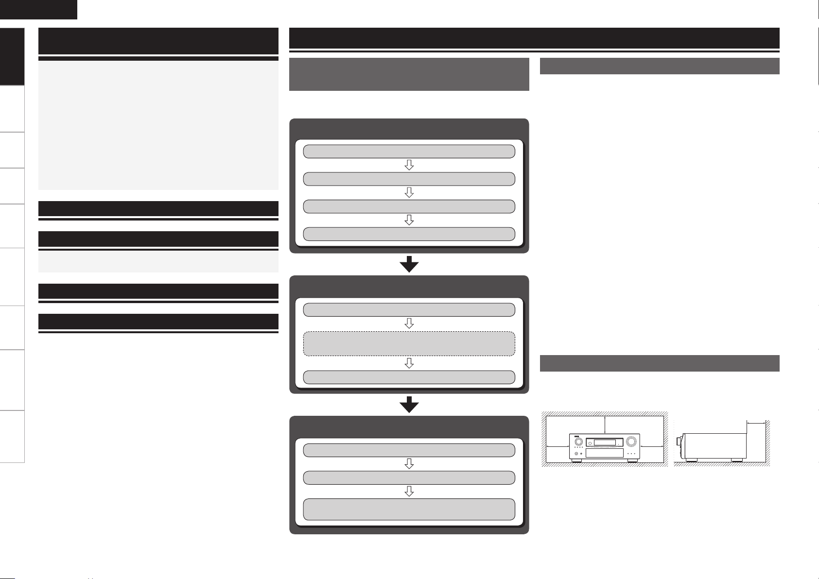
Flow of Operations Through
Playback
Perform the operations leading to playback on the AVR-3310 in the
order shown below.
Connections
Installing/Setting the Speakers
Speaker Connections (vpage 13)
Connecting Devices (vpage 14)
Turning the Power On (vpage 23)
(vpage 11)
Settings
Audyssey™ Auto Setup (vpage 27)
Manual Setup (vpage 32)
Perform “Manual Setup” as necessary.b
Cautions on Handling
• Before turning the power switch on
Check once again that all connections are correct and that there are
no problems with the connection cables.
• Power is supplied to some of the circuitry even when the unit is
set to the standby mode. When traveling or leaving home for long
periods of time, be sure to unplug the power cord from the power
outlet.
• About condensation
If there is a major difference in temperature between the inside of
the unit and the surroundings, condensation (dew) may form on
the operating parts inside the unit, causing the unit not to operate
properly.
If this happens, let the unit sit for an hour or two with the power
turned off and wait until there is little difference in temperature
before using the unit.
• Cautions on using mobile phones
Using a mobile phone near this unit may result in noise. If so, move
the mobile phone away from this unit when it is in use.
• Moving the unit
Turn off the power and unplug the power cord from the power
outlet.
Next, disconnect the connection cables to other system units before
moving the unit.
• Note that the illustrations in these instructions may differ from the
actual unit for explanation purposes.
Cautions on Installation
Input Setup (vpage 43)
Playback
Playing Components (vpage 50)
Selecting the Surround Mode (vpage 64)
Adjusting the Sound and Picture Quality
(vpage 67)
Note:
For proper heat dispersal, do not install this unit in a confined
space, such as a bookcase or similar enclosure.
b
b Note
b b
Wall
Page 7

Preparations
r t u
Q1
o
Q0
Thank you for purchasing this DENON product. To ensure proper
operation, please read this owner’s manual carefully before using the
product.
After reading them, be sure to keep them for future reference.
Accessories
Check that the following parts are supplied with the product.
q Owner’s manual ...................................................................... 1
w Getting started ........................................................................1
e Service station list ...................................................................1
r Power cord (Cord length: Approx. 1.7 m) ................................ 1
t Main remote control unit (RC-1118) ........................................ 1
y R6/AA batteries (for RC-1118) ................................................. 2
u Sub remote control unit (RC-1121) .......................................... 1
i R03/AAA batteries (for RC-1121) ............................................. 2
o FM indoor antenna ..................................................................1
Q0 AM loop antenna ..................................................................... 1
Q1 Setup microphone
(DM-A409, Cord length: Approx. 7.6 m) .................................. 1
Insert Batteries in the Remote Control
Unit
In addition to the AVR-3310, the included main remote control unit
(RC-1118) can also be used to operate the equipment listed below.
q DENON system components
w Non-DENON system components
To operate component products other than DENON, you must set
the preset code (vpage 83 “Registering Preset Codes”).
Inserting the Batteries
q Lift the clasp and remove the rear lid.
(RC-1118) (RC-1121)
w Load the two batteries properly as indicated by the marks in the
battery compartment.
(RC-1118) (RC-1121)
R6/AA
R03/AAA
ENGLISH
NOTE
Insert the specified batteries in the remote control unit.
•
Replace the batteries with new ones if the set does not operate
•
even when the remote control unit is operated close to the unit. (The
supplied batteries are only for verifying operation.)
When inserting the batteries, be sure to do so in the proper direction,
•
following the “q” and “w” marks in the battery compartment.
To prevent damage or leakage of battery fluid:
•
Do not use a new battery together with an old one.
•
Do not use two different types of batteries.
•
Do not attempt to charge dry batteries.
•
Do not short-circuit, disassemble, heat or dispose of batteries in
•
flames.
If the battery fluid should leak, carefully wipe the fluid off the inside
•
of the battery compartment and insert new batteries.
Remove the batteries from the remote control unit if it will not be in
•
use for long periods.
Used batteries should be disposed of in accordance with the local
•
regulations regarding battery disposal.
Operating Range of the Remote Control
Unit
Point the remote control unit at the remote sensor when operating it.
Getting Started
Connections Settings Playback Remote ControlMulti-zone Information Troubleshooting Specifications
e Put the rear cover back on.
30°
(RC-1121)
30°
or
Approx. 7 m
(RC-1118)
NOTE
The set may function improperly or the remote control unit may not
operate if the remote control sensor is exposed to direct sunlight,
strong artificial light from an inverter type fluorescent lamp or infrared
light.
Page 8

ENGLISH
t
q
w
e
r
Q5 Q6Q4Q3
y
o
Q0
Q1
Q2
ui
W5
Q7
Q8
Q9
W0
W1 W4W3W2
E1
E6
W9E0
E4E5
E2
E3
W8
W7 W6
Getting Started
Part Names and Functions
Front Panel
For buttons not explained here, see the page indicated in parentheses ( ).
Connections Settings Playback Remote ControlMulti-zone Information Troubleshooting Specifications
GWith the door openH
q Power operation button ···························· (23)
w Power indicator ·········································· (23)
e Power switch ··············································(23)
r Door
When you are using buttons and/or terminals
behind the door, press the bottom of the door to
open it. When not using buttons and/or terminals
behind the door, close it. Be careful not to catch
your fingers when closing the door.
t QUICK SELECT buttons ····························· (77)
y MASTER VOLUME control knob ··············· (62)
u AUDYSSEY
DYNAMIC VOLUME™ indicator ················ (69)
i HD AUDIO indicator ···································· (65)
o Master volume indicator
Q0 Display
Q1 Remote control sensor ································ (3)
Q2 SOURCE SELECT knob ······························ (26)
Q3 SOURCE button ·········································· (26)
Q4 TUNING PRESET button ···························· (52)
Q5 ZONE 2/3 / REC SELECT button ··········(74, 82)
Q6 VIDEO SELECT button ······························· (46)
Q7 Headphones jack ········································ (62)
Q8 ZONE2 ON/OFF button ······························ (82)
Q9 ZONE3 ON/OFF button ······························ (82)
W0 FRONT SPEAKERS button ························· (62)
W1 MENU button ·············································· (24)
W2 Cursor buttons (uio p) ·························· (25)
W3 ENTER button ·············································(25)
W4 RETURN button ··········································(25)
W5 V.AUX INPUT connectors ·························· (20)
W6 SETUP MIC jack ·········································· (28)
W7 MULTEQ
®
button ······································· (69)
W8 DYNAMIC VOLUME™ button (DYN VOL) ··· (70)
W9 USB port ······················································ (20)
E0 STATUS button ·········································· (73)
E1 AUDIO DELAY button ································ (71)
E2 RESTORER button ······································ (71)
E3 DIRECT/STEREO button ···························· (65)
E4 PURE DIRECT button ································· (66)
E5 DSP SIMULATION button ·························· (65)
E6 STANDARD button ····································· (64)
Page 9
ioQ5
Q8
W0 Q0Q1
Q6
Q2Q4
Q3
Q7Q9 u
wq e r t y
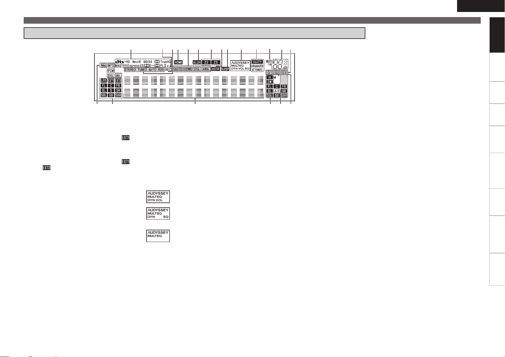
Display
ENGLISH
Part Names and Functions
Getting Started
Connections Settings Playback Remote ControlMulti-zone Information Troubleshooting Specifications
q Input signal indicators
w Input signal channel indicators
These light when digital signals are input.
When playing HD Audio sources, the“ ”
indicator lights when an extension channel (a
channel other than the front, center, surround,
surround back or LFE channel) is input. If there
are two or more extension channels, the “ ”
and “ ” indicators light.
e Information display
The input source name, surround mode, setting
values and other information are displayed
here.
r Output signal channel indicators
t Front speaker indicators
These light according to the settings of the front
A and B speakers.
y Monitor output indicators
This indicator lights up when an HDMI monitor
is connected.
u QUICK SELECT indicators
i Master volume indicator
o MUTE indicator
This lights when the mute mode is selected.
Q0 PARTY indicators
These indicators light during party mode.
• ORGANIZER
This lights to indicate that party mode has
started as Organizer.
• ATTENDEE
This lights to indicate that party mode has
started as Attendee.
Q1 AUDYSSEY MULTEQ indicators
Lighting is as follows, depending on the setting
of “Dynamic EQ” (vpage 69) and “Dynamic
Volume” (vpage 70).
•
•
•
: When “Dynamic EQ” and “Dynamic
Volume” are “ON”.
: When the “Dynamic EQ” setting is
“ON” and the “Dynamic Volume”
setting is “OFF”.
: When “Dynamic EQ” and “Dynamic
Volume” are “OFF”.
Q2 SLEEP indicator
This lights when the sleep mode is selected.
Q3 RESTORER indicator
This lights when the RESTORER mode is
selected.
Q4 Multi zone indicators
These light when the power for the respective
zone is turned on.
Q5 AL24 indicator
This lights when AL24 Processing Plus (vpage
91) is activated.
Q6 Input mode indicators
Q7 HDMI indicator
This lights when playing using HDMI
connections.
Q8 Tuner reception mode indicators
These light according to the reception conditions
when the input source is set to “TUNER”.
• STEREO
In the FM mode, these light when receiving
analog stereo broadcasts.
• TUNED
Lights when the broadcast is properly tuned in.
• AUTO
These light when in the auto tuning mode.
• RDS
These light when receiving RDS broadcasts.
Q9 Recording output source indicator
This lights when the REC OUT mode is
selected.
W0 Decoder indicators
These light when the respective decoders are
operating.
Page 10
ENGLISH
t
e
y
Q0
u
i
o
Q1
Q5
Q5
o
r
wq
Q2
Q3Q4
Q6Q7Q6
Getting Started
Part Names and Functions
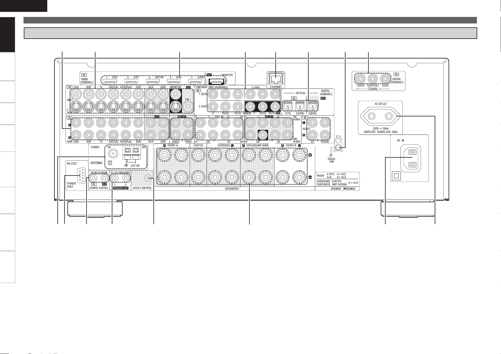
Rear Panel
Connections Settings Playback Remote ControlMulti-zone Information Troubleshooting Specifications
q FM/AM antenna terminals ························ (19)
w RS-232C connector ····································· (21)
e REMOTE CONTROL jacks ·························· (21)
r TRIGGER OUT jacks ··································· (21)
t DOCK CONTROL jack ································· (16)
y Speaker terminals ······································ (13)
u AC inlet ························································ (23)
i AC OUTLET ················································· (23)
o Digital audio connectors ···················· (16 ~ 19)
Q0 SIGNAL GND terminal ······························· (17)
Q1 ETHERNET connector ································ (22)
Q2 COMPONENT VIDEO connectors ···(15, 16, 18)
Q3 HDMI connectors ········································ (14)
Q4 VIDEO / S-VIDEO connectors ············ (15 ~ 19)
Q5 Analog audio connectors ··················· (16 ~ 19)
Q6 PRE OUT connectors ···························· (21, 81)
Q7 EXT. IN connectors ····································· (20)
Page 11

w
q
e
t
r
y
u
i
o
Q0
Q2
Q1
Q3
Q4
Q5
Q6
Q7
W0
Q9
r
Q8
W1
W3
E0
W9
W6
W5
W4
W7
W8
W2
Remote Control Unit
Main Remote Control Unit (RC-1118)
Front
Rear
q Indicator ······················································(83)
w Power buttons ············································ (23)
e QUICK SELECT buttons ·····························(77)
r Input source select button ························ (26)
t System buttons ····························(62, 84 ~ 86)
y MENU button ··············································(24)
u Cursor buttons (uio p) ························· (25)
i SEARCH button ··········································(63)
o SOURCE SELECT button ··························· (26)
Q0 DEVICE SELECT switches ·······················(7, 83)
Q1 Remote control signal transmitter ············· (3)
Q2 Master volume control buttons ················ (62)
Q3 Muting button (MUTE) ······························ (62)
Q4 Channel level adjustment button ······· (34, 76)
Q5 RETURN button ·········································· (25)
Q6 ENTER button ············································· (25)
Q7 ZONE power button ··································· (82)
Q8 VIDEO SELECT button ·······························(46)
Q9 Front height speaker on/off button ·········· (68)
W0 Tuner operation buttons ··························· (52)
W1 MULTEQ
®
button ······································· (69)
W2 Number buttons (0 ~ 9, +10) ····················· (83)
W3 MAIN ZONE power buttons ······················(23)
W4 SLEEP TIMER button ·································· (76)
W5 INPUT MODE button ·································· (47)
W6 RESTORER button ······································ (71)
W7 PARTY button ············································· (77)
W8 Surround mode buttons ····················(64 ~ 66)
W9 DYNAMIC VOLUME™ button···················· (70)
E0 DYNAMIC EQ™ button ······························(69)
For buttons not explained here, see the page
indicated in parentheses ( ).
NOTE
Buttons on the back panel may operate when the
•
back lid is pressed.
The SAT TU and HDMI CONTROL buttons cannot
•
be used.
ENGLISH
Part Names and Functions
Operations possible by remote
control
Operations on the AVR-3310
n
Operations on five devices other that
n
the AVR-3310
• Preset the remote control codes of the devices
to be operated (vpage 83).
• Switch two device selector switches according
to the devices to be operated.
Position of switches
Operable devices
AVR-3310
(MAIN ZONE)
iPod, TUNER,
NET/USB
AVR-3310 (ZONE2)
AVR-3310 (ZONE3)
TV
Blu-ray disc player
or
DVD Player
Dgital video
recorder
or
Video deck
Satellite receiver
or
Cable TV
CD player
Multi-zone (ZONE2 / ZONE3)
n
operations (vpage 82)
Punch through setting (vpage 87)
n
Getting Started
Connections Settings Playback Remote ControlMulti-zone Information Troubleshooting Specifications
Page 12
ENGLISH
q
t
r
y
i
o
Q0
u
e
w
Q6
Q5
Q8
W0
W1
W2
W3
Q9
Q7
Q2
Q3
Q4
Q1
Getting Started Connections Settings Playback Remote ControlMulti-zone Information Troubleshooting Specifications
Getting Started
Part Names and Functions
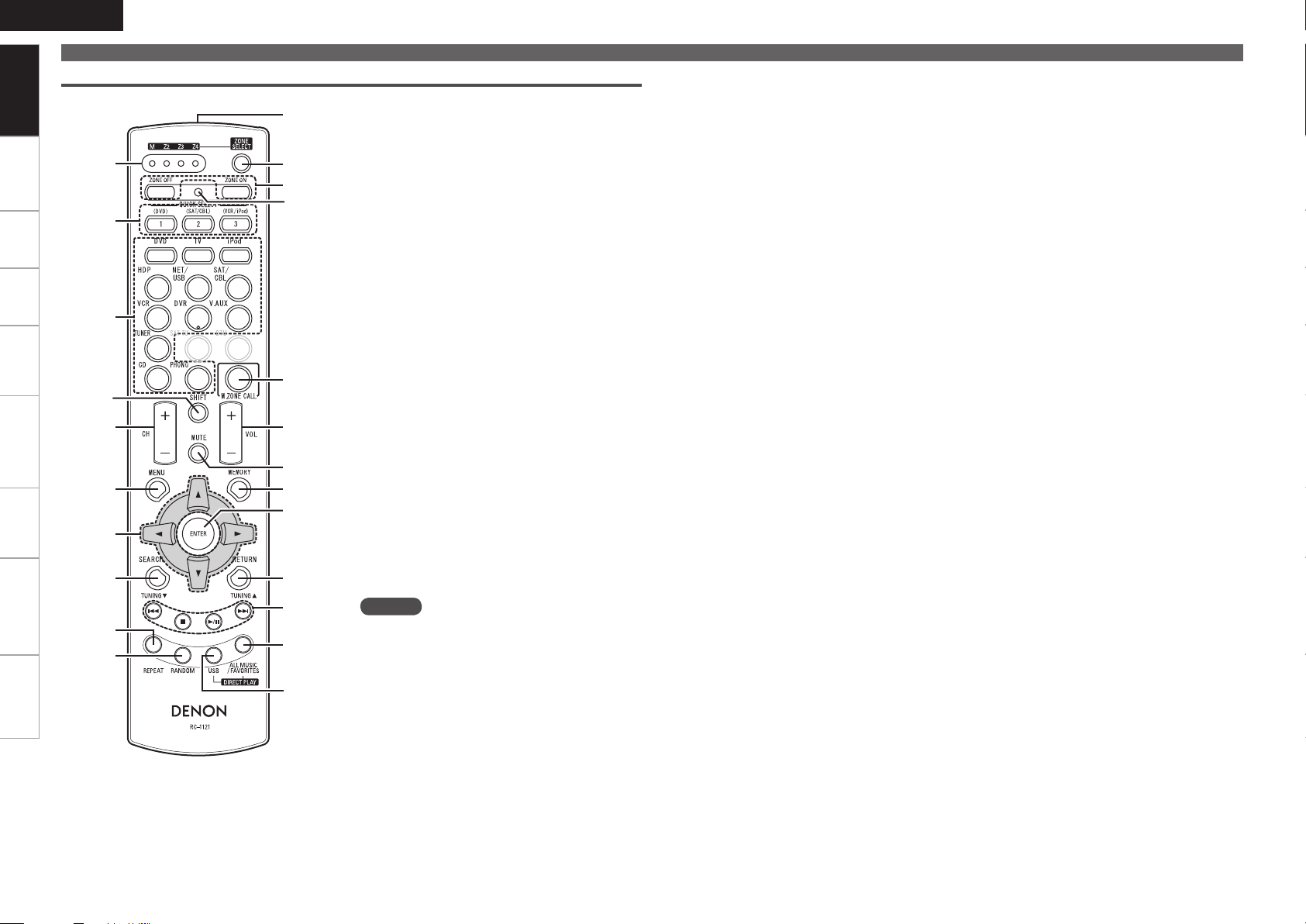
Sub Remote Control Unit (RC-1121)
q ZONE indicators ········································· (89)
w QUICK SELECT buttons ························(77, 83)
e Input source select buttons ················· (26, 88)
r SHIFT button ··········································(57, 88)
t Channel button (CH) ···························· (52, 88)
y MENU button ········································ (24, 88)
u Cursor buttons (uio p) ···················· (25, 88)
i SEARCH button ···································· (63, 88)
o REPEAT button ·····································(63, 88)
Q0 RANDOM button ·································· (63, 88)
Q1 Remote control signal transmitter ············· (3)
Q2 ZONE SELECT button ································ (89)
Q3 Zone power on/off buttons ······················· (82)
Q4 Advanced setup button ····························· (89)
Q5 MAIN ZONE call button ······················· (82, 89)
Q6 Master volume control buttons
(VOL) ······················································ (62, 82)
Q7 Muting button (MUTE) ························ (62, 82)
Q8 MEMORY button ·································· (52, 88)
Q9 ENTER button ·······································(25, 88)
W0 RETURN button ····································(25, 88)
W1 System buttons ····································(62, 88)
W2 ALL MUSIC/FAVORITES
(DIRECT PLAY) button ······························· (88)
W3 USB (DIRECT PLAY) button ················· (59, 88)
NOTE
The SAT TU and DTU buttons cannot be used.
Page 13
Connections
R
L
R
L
ENGLISH
Getting Started Settings Playback Remote ControlMulti-zone Information Troubleshooting Specifications
Important Information
Connections for all compatible audio and video signal formats
are described in this owner’s manual. Please select the types of
connections suited for the equipment you are connecting.
After connections are completed, certain settings must be made on
the receiver. Make the settings indicated “
for the individual items.
NOTE
• Do not plug in the power cord until all connections have been completed.
• When making connections, also refer to the operating instructions
of the other components.
• Be sure to connect the left and right channels properly (left with
left, right with right).
• Do not bundle power cords together with connection cables. Doing
so can result in humming or noise.
Set as Necessary
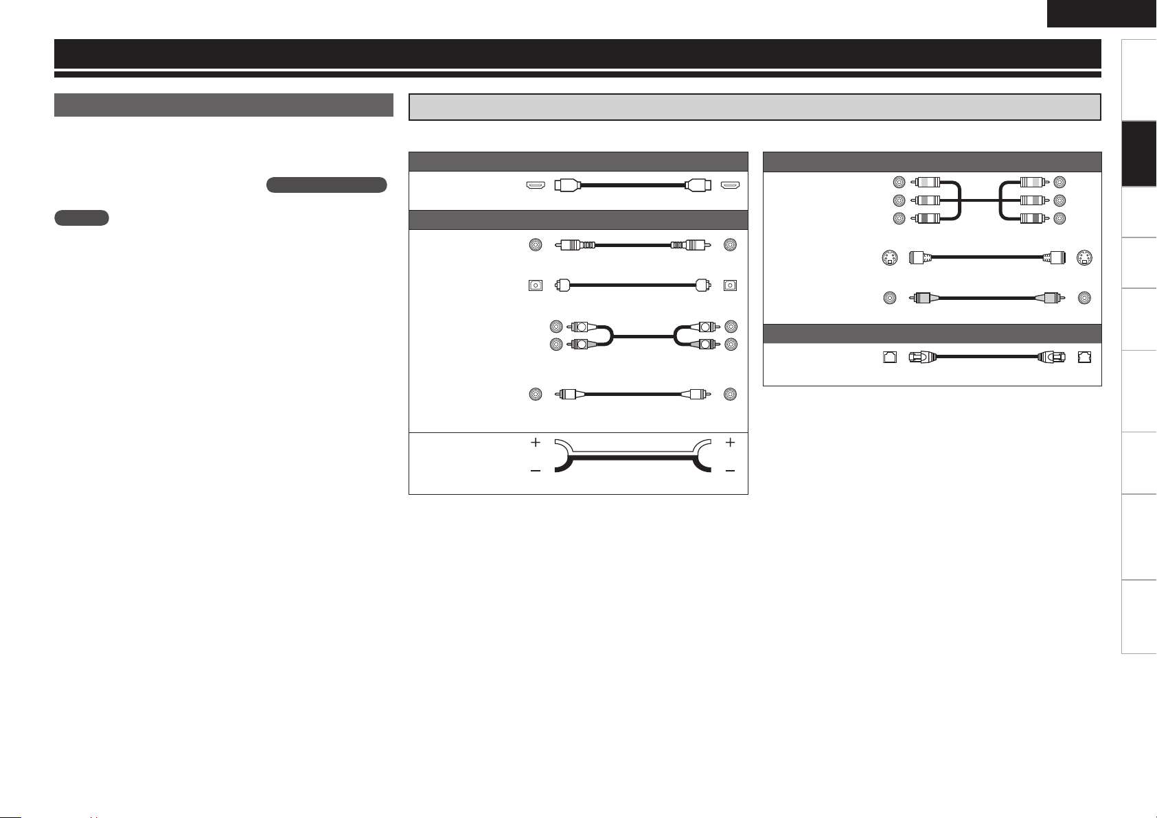
Cables Used for Connections
Select the cables (sold separately) according to the equipment being connected.
Audio and video cables
HDMI connections
”
HDMI cable
Audio cables
Coaxial digital
connections
Optical digital
connections
Analog
connections
(stereo, surround)
Analog
connections
(monaural, for
subwoofer)
Speaker
connections
(White)
(Red)
Coaxial digital cable
Optical cable
Audio cable
Audio cable
Speaker cables
Component
video
connections
S-Video
connections
Video
connections
Network
connections
Connections
Video cables
(Green)
(Blue)
(Red)
Component video cable
S-Video cable
(Yellow)
Video cable
Other cables
Ethernet cable
Page 14

ENGLISH
Getting Started Connections Settings Playback Remote ControlMulti-zone Information Troubleshooting Specifications
Important Information
Converting Input Video Signals for Output
(Video Conversion Function)
The AVR-3310 has 4 different types of video input/output terminal (HDMI, Component video, S-Video,
Connections
Video).
Use the terminals according to the devices to be connected.
This function automatically converts various formats of video signals input to the AVR-3310 into the format
used to output the video signals from the AVR-3310 to a monitor (vpage 96 “Relationship Between
Video Signals and Monitor Output”).
GFlow of video signals for MAIN ZONEH
AVR-3310
Video device
Monitor
Video device
Output
S-Video connector
Video connector
GFlow of video signals for ZONE2H
AVR-3310
Input
(IN)
S-Video connector
Video connector Video connector Video connector
Output
(MONITOR OUT)
Monitor
Input
Output
HDMI connector
Component video
connectors
S-Video connector
Video connector
Input
(IN)
HDMI connector
Component video
connectors
S-Video connector
Video connector
Output
(MONITOR OUT)
HDMI connector
Component video
connectors
S-Video connector S-Video connector
Video connector
: When 480i/576i signals are input
Input
HDMI connector
Component video
connectors
Video connector
Set as Necessary
Set when using the video conversion function.
•
“Video Convert” (vpage 46)
Set when changing the resolution of the video signal.
•
“Resolution” (vpage 47)
Resolutions of HDMI-compatible TVs can be checked at “HDMI Information” – “Monitor Information”
(vpage 73).
NOTE
HDMI signals cannot be converted into analog signals.
•
When a non-standard video signal from a game machine or some other source is input, the video
•
conversion function might not operate.
480p/576p/1080i/720p/1080p component video input signals cannot be converted into S-Video or Video
•
format.
0
Page 15
z1
z
3
z
2
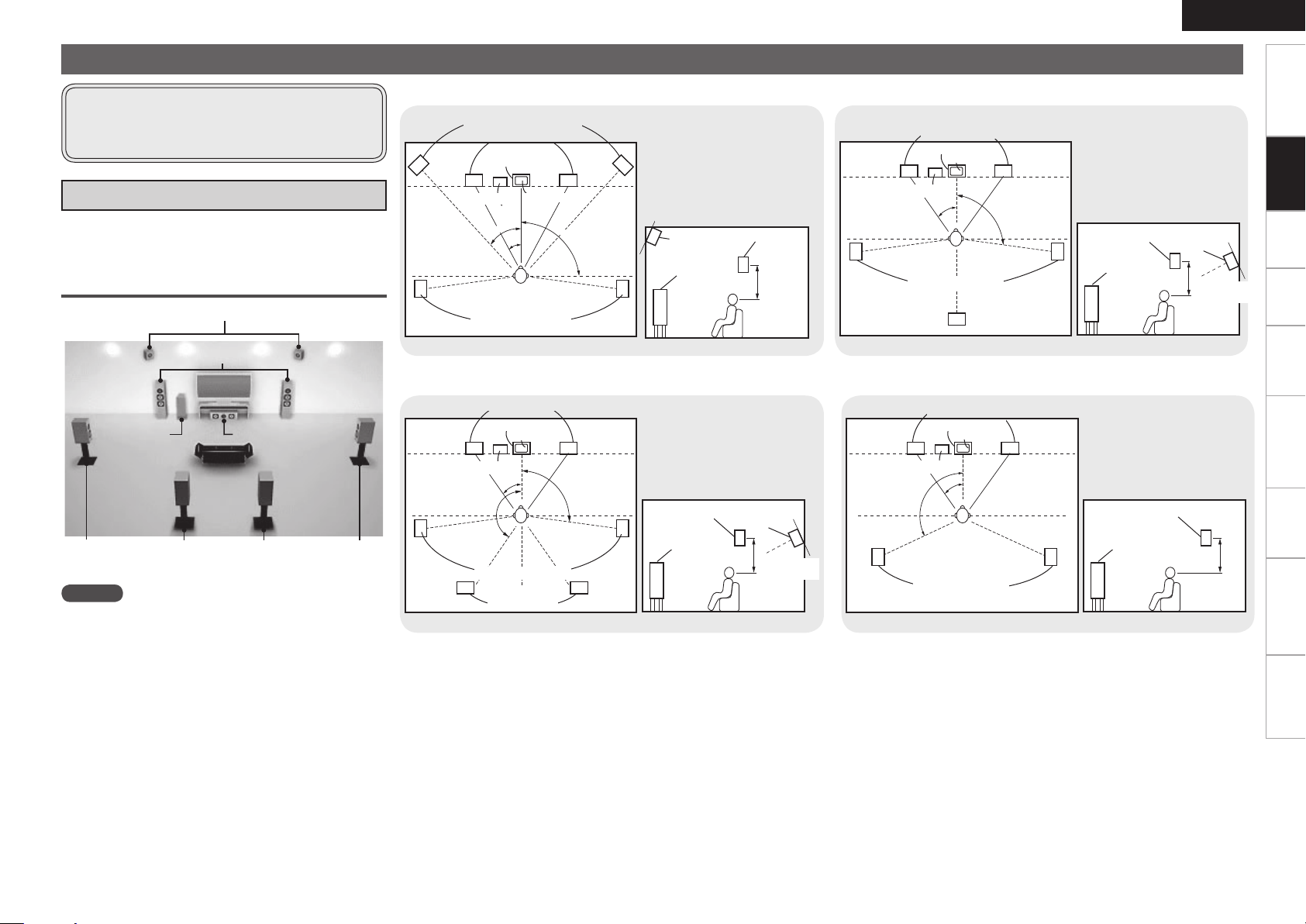
Installing / Setting the Speakers
z
2
z
1
z3
z
1
z
2
z1
z2
ENGLISH
Getting Started Settings Playback Remote ControlMulti-zone Information Troubleshooting Specifications
• The AVR-3310 is compatible with various types of
surround playback.
• Decide on the surround modes to be played on the
AVR-3310 before making connections and settings.
a Determine the Speaker Layout
Below we introduce examples of speaker layouts. Refer to
these to arrange your speakers according to their type and
how you want to use them.
Installing All the Speakers
Front Height speakers
Front speakers
Subwoofer
Surround
Surround back speakers
speaker
NOTE
It is not possible to use the surround back speakers and
front height speakers simultaneously.
Center speaker
Surround
speaker
When 7.1ch (Front Height Speaker) Connectedn
Front height speakers
Front speakers
Center speaker
z1: 22˚ ~ 30˚
z2: 22˚ ~ 45˚
z3: 90˚ ~ 110˚
Subwoofer
Surround speakers
As seen from above
G
Monitor
Point slightly
downwards
Front height
speaker
Front speaker
60 to 90 cm
H
As seen from the side
G
Surround
speaker
H
When 7.1ch (Surround Back Speaker) Connectedn
Front speakers
Center speaker
Monitor
z1: 22 ~ 30˚
z2: 90˚ ~ 110˚
When 6.1ch (Surround Back Speaker) Connectedn
Front speakers
Center speaker
Monitor
Subwoofer
Surround speakers
Surround back
As seen from above
G
speaker
H G
z1: 22 ~ 30˚
z2: 90˚ ~ 110˚
Surround
speaker
Front
speaker
60 to 90 cm
As seen from the side
Surround back
speaker
Point slightly
downwards
H
Connections
When 5.1ch Connectedn
Front speakers
Center speaker
Monitor
z1: 22 ~ 30˚
z2: 120˚
z3: 135˚ ~ 150˚
Subwoofer
Surround speakers
Surround back
speakers
As seen from above
G
Surround
speaker
Front
speaker
H
As seen from the side
G
Surround back
speaker
60 to 90 cm
Point slightly
downwards
H
Subwoofer
Surround speakers
As seen from above
G
Front
speaker
H G
Surround
speaker
60 to 90 cm
As seen from the side
H
Page 16
ENGLISH
Getting Started Settings Playback Remote ControlMulti-zone Information Troubleshooting Specifications
Installing/Setting the Speakers
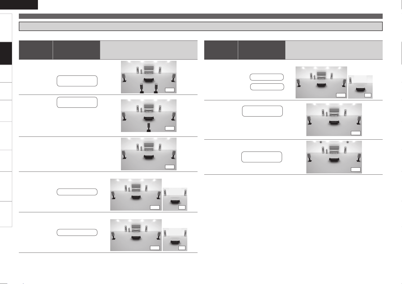
s Set the “Amp Assign” Mode According to the Speaker Layout
The signals output from the AVR-3310’s SURR. BACK/AMP ASSIGN speaker terminals can be switched (vpage 33 “Amp Assign”).
Connections
Amp assign
mode
(vpage 33)
SURR. BACK /
AMP ASSIGN
Speaker connections
Example of speaker installation
(Number of channels played)
Amp assign
(vpage 33)
mode
SURR. BACK /
AMP ASSIGN
Speaker connections
Example of speaker installation
(Number of channels played)
MAIN ZONE ZONE2 or ZONE3
Normal
(Default)
Normal
Normal
ZONE2
Surround Back
Speakers
Surround Back L
Speaker
Connect to the “L”
b
speaker terminal.
Set “Surround Back”
b
(vpage 33) to
“1spkr”.
Not connected
Set “Surround Back”
b
(vpage 33) to
“None”.
ZONE2 speakers
(7.1)
(6.1)
(5.1)
MAIN ZONE ZONE2
(5.1) (2)
ZONE2/3-MONO
Front A Bi-Amp
or
Front B Bi-Amp
Front Height
ZONE2 speaker
L ch :
ZONE3 speaker
R ch :
Front A or B
speakers
For connections,
b
see “About Bi-amp
Connections” (vpage
13).
Front height
Speakers
(5.1) (1)
(5.1)
(7.1)
ZONE3
ZONE3 speakers
MAIN ZONE ZONE3
(5.1) (2)
Page 17
w q
w q
w q w q
*/
w q
(R)
(L) (R)
w q w q
(L) (R) (L)
wq wq
(R) (L)
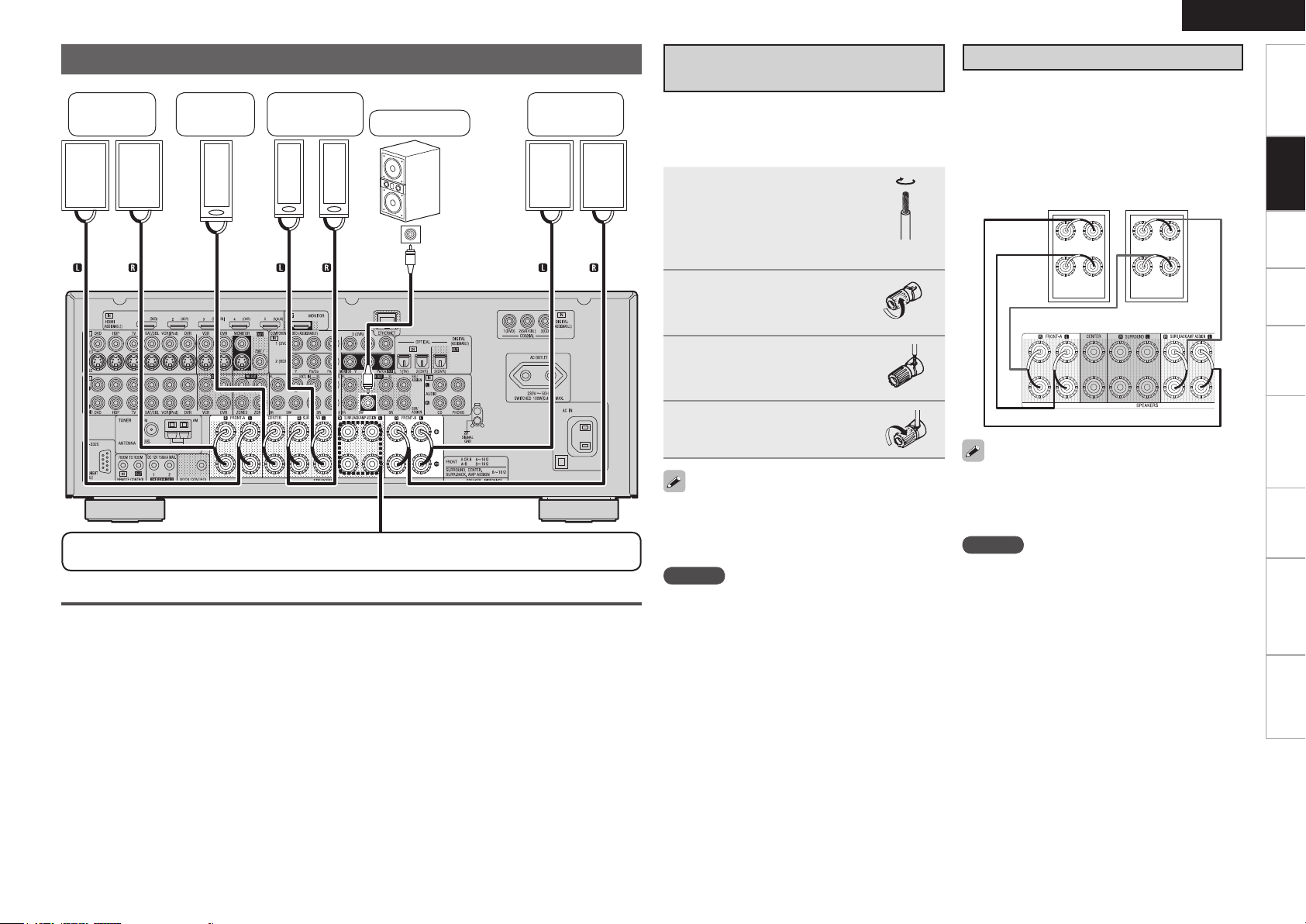
Speaker Connections
Front
speakers A
Center
speaker
Surround
speakers
Subwoofer
Subwoofer
with built-in
amplifier
Front
speakers B
Connecting the Speaker
Cables
Carefully check the left (L) and right (R) channels
and + (red) and – (black) polarities on the speakers
being connected to the AVR-3310, and be sure to
interconnect the channels and polarities correctly.
Peel off about 10 mm of
1
sheathing from the tip of
the speaker cable, then
either twist the core wire
tightly or terminate it.
Turn the speaker terminal
2
counterclockwise to
loosen it.
Insert the speaker cable’s
3
core wire to the hilt into
the speaker terminal.
Turn the speaker terminal
4
clockwise to tighten it.
ENGLISH
About Bi-amp Connections
These connections make for higher quality playback
sound with no interference between the signals of
the bass and treble units.
When the “Amp Assign” setting (vpage 33) is
“Front A Bi-Amp” or “Front B Bi-Amp”, connect
as follows. (The illustration shows a connection
example for the Front A Bi-Amp speakers.)
Front speakers A
AVR-3310
Getting Started Settings Playback Remote ControlMulti-zone Information Troubleshooting Specifications
Connections
For connections of the SURR. BACK/AMP ASSIGN speaker terminals, see “Set the “Amp Assign”
Mode According to the Speaker Layout” (vpage 12).
Protection Circuit
If the core wires touch the rear panel and the
screws etc., or the ± sides touch each other, the
protection circuit will be activated and the power
indicator will flash red at intervals of 0.5 secs.
If the protection circuit is activated, the speaker
output is isolated, and the power supply goes to
the standby state. If the power supply is turned off,
after the power supply cord is withdrawn, please
confirm that speaker cable and input cable are
connected.
Also, if replaying large sound levels by using
a speaker having an impedance less than that
specified (eg, 4 Ω/ohms), the temperature will rise,
and the protection circuit might be activated. The
power supply will go into the standby state, and the
power indicator will flash red at 2 second intervals.
In this case, please switch off the power supply,
and wait until the AVR-3310 has cooled down, and
the surrounding ventilation is good.
Even if there are no problems with the surrounding
ventilation and connections, in the event of the
protection circuit becoming activated, due to
thinking that the AVR-3310 has failed, please
contact DENON Service center after switching off.
Use speakers with an impedance of 6 to 16 Ω/ohms.
When using front A and B speakers simultaneously,
use speakers with an impedance of 8 to 16 Ω/
ohms.
NOTE
Connect so that the speaker cable core wires
•
do not protrude from the speaker terminal. The
protection circuit may be activated if the core
wires touch the rear panel or if the + and – sides
touch each other (v“Protection Circuit”).
Never touch the speaker terminals while the
•
power supply is connected. Doing so could result
in electric shock.
When in the “Front A Bi-Amp” and “Front B BiAmp” modes, the same signals are output from
the front speaker terminals and the AMP ASSIGN
terminals.
NOTE
Use speakers compatible with bi-amp
•
connections.
When making bi-amp connections, be sure to
•
remove the short-circuiting plate or wire between
the speaker’s woofer and tweeter terminals.
Page 18
ENGLISH
065
)%.*
065
)%.*
065
)%.*
065
)%.*
065
)%.*
*/
)%.*
Getting Started Settings Playback Remote ControlMulti-zone Information Troubleshooting Specifications
Connecting Devices
Connections
n
n
n
n
n
n
n
Connecting Devices
Connecting Devices Equipped with HDMI
Terminals (vpage 14)
Connecting the Monitor (vpage 15)
Connecting the Playback Components
Blu-ray Disc Player / DVD Player (vpage 16)
•
Control dock for iPod (vpage 16)
•
CD Player (vpage 17)
•
Record Player (vpage 17)
•
Connecting the Recording Components
Video Cassette Recorder (vpage 17)
•
Digital Video Recorder (vpage 18)
•
Connect the Tuner
TV (vpage 18)
•
Satellite Receiver / Cable Tuner (vpage 19)
•
FM/AM (vpage 19)
•
Connections to Other Devices
Video Camera / Game Console (vpage 20)
•
USB Port (vpage 20)
•
Component with Multi-channel Output connectors
•
(vpage 20)
External Power Amplifier (vpage 21)
•
External Controller (vpage 21)
•
Connecting to a Home Network (LAN) (vpage 22)
Connecting Devices Equipped with
HDMI Terminals
Important Information
About HDMI
n
“HDMI” is the abbreviation of “High Definition Multimedia
Interface”. This interface allows transfer of digital video signals and
digital audio signals over a single HDMI cable.
“HDMI”, “HDMI logo” and “High-Definition Multimedia
Interface” are trademarks or registered trademarks of HDMI
Licensing LLC.
Functions Usable with HDMI Connections
n
Deep Color
Eliminates on-screen color banding, for smooth tonal transitions
and subtle gradations between colors. Enables increased contrast
ratio.
x.v.Color
Lets HDTVs display colors more accurately. Enables displays with
natural, vivid colors. “x.v.Color” is a Sony registered trademark.
Auto Lip Sync (vpage 35)
If you connect the receiver to a TV that supports the Auto Lip Sync
function, it can automatically correct delay between the audio and
video.
HDMI Control Function (vpage 75)
This function allows you to operate external devices from the
receiver and operate the receiver from external devices.
NOTE
These functions will not work if the device connected to the
•
HDMI terminal does not support Deep Color or x.v.Color signal
transfer or the Auto Lip Sync function.
The HDMI control function may not work depending on the
•
device it is connected to and its settings.
You cannot operate a TV or Blu-ray Disc player / DVD player that
•
is not compatible with the HDMI control function.
Copyright Protection System (HDCP)
n
The AVR-3310 supports HDCP (High-bandwidth Digital Contents
Protection). HDCP is a copyright protection technology for digital
video signals. The devices connected to the AVR-3310 must also
support HDCP.
NOTE
When a device that does not support HDCP is connected, video
signals are not properly output.
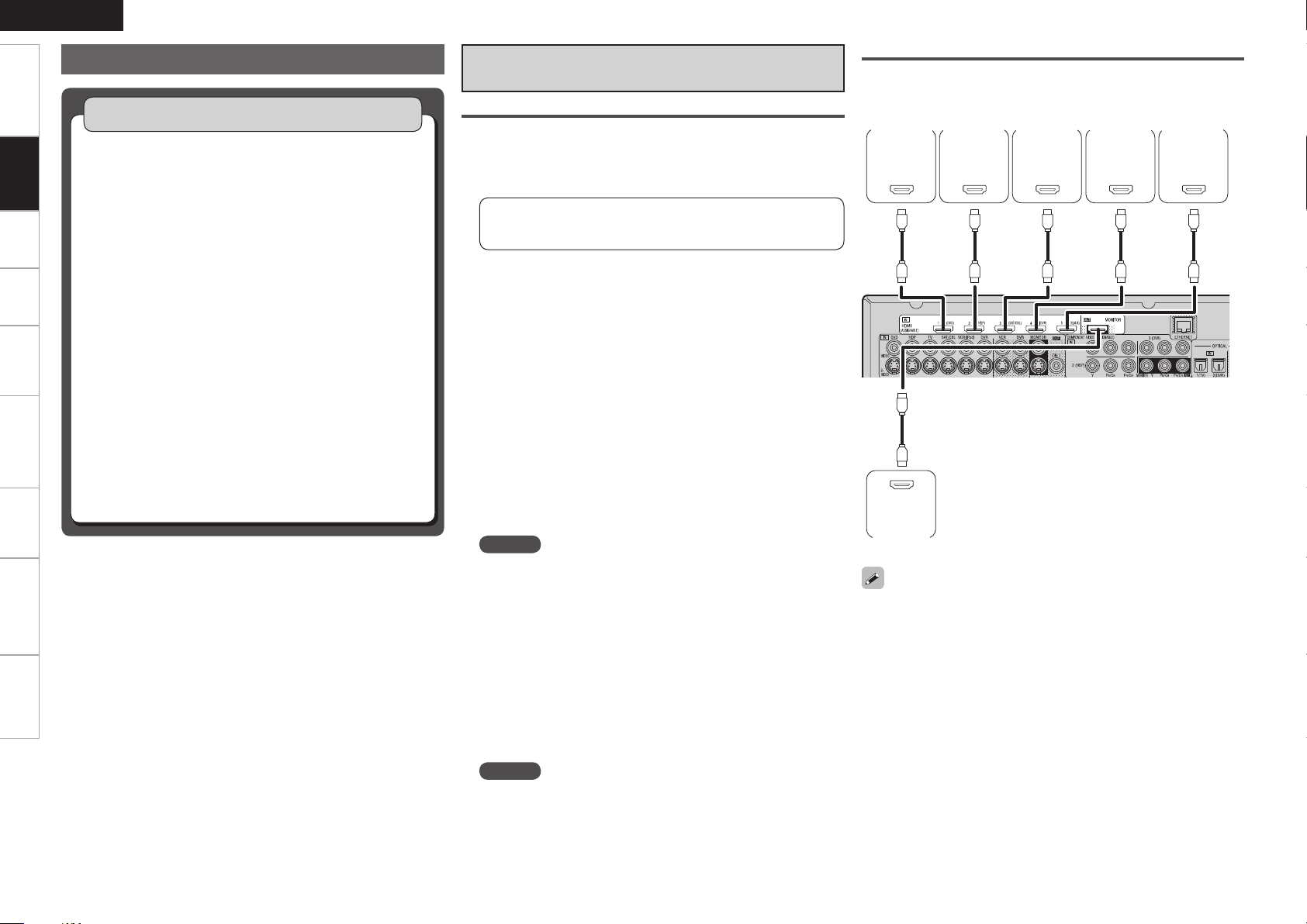
Connections
The AVR-3310 allows connection of inputs from up to 5 HDMI devices
and output to 1 monitor.
DVD
player
Monitor
Use a cable on which the HDMI logo is indicated (a certified HDMI
•
product) for connection to the HDMI connector. Normal playback
may not be possible when using a cable other than one on which the
HDMI logo is indicated (a non-HDMI-certified product).
When the AVR-3310 is connected to other devices with HDMI
•
cables, also connect the AVR-3310 and TV using an HDMI cable.
When a device supporting Deep Color signal transfer is connected,
•
use a cable compatible with HDMI version 1.3a.
Video signals are not output if the input video signals do not match
•
the monitor’s resolution. In this case, switch the Blu-ray Disc/
DVD player’s resolution to a resolution with which the monitor is
compatible.
HD player
Satellite
receiver
Digital
video
recorder
Game
console
Page 19
ENGLISH
*/
7*%&0
$0.10/&/57*%&0
: 1# 13
7*%&0
*/
47*%&0
*/
Connecting Devices
Getting Started Settings Playback Remote ControlMulti-zone Information Troubleshooting Specifications
NOTE
If the GUI menu “Audio Out” setting (vpage 35) is set to “AMP”, the sound may be interrupted when
•
the monitor’s power is turned off.
The audio signal from the HDMI output terminal (sampling frequency, number of channels, etc.) may be
•
limited by the HDMI audio specifications of the connected device regarding permissible inputs.
Connecting to a Device Equipped with a DVI-D Terminal
n
When an HDMI/DVI conversion cable (sold separately) is used, the HDMI video signals are converted
to DVI signals, allowing connection to a device equipped with a DVI-D terminal.
NOTE
No sound is output when connected to a device equipped with a DVI-D terminal. Also make the audio
•
connections.
Signals cannot be output to DVI-D devices that do not support HDCP.
•
Depending on the combination of devices, the video signals may not be output.
•
Settings Related to HDMI Connections
Set as necessary. For details, see the respective reference pages.
Input Assign (vpage 44)
n
Set this to change the HDMI input terminal to which the input source is assigned.
HDMI Setup (vpage 35)
n
Make settings for HDMI video/audio output.
RGB Range
•
Auto Lip Sync
•
NOTE
The audio signals output from the HDMI connectors are only the HDMI input signals.
Audio Out
•
HDMI Control
•
Connecting the Monitor
Select the terminal to use and connect the device.
•
For video connections, see “Converting Input Video Signals for Output (Video Conversion Function)”
•
(vpage 10).
For instructions on HDMI connections, see “Connecting Devices Equipped with HDMI Terminals” on
page 14.
Monitor
Connections
To listen to TV audio through this device, use the optical digital or analog connection.
Page 20
ENGLISH
R
L
R
L
065
7*%&0
$0.10/&/57*%&0
: 1# 13
7*%&0
065
47*%&0
065
"6%*0
"6%*0
3-
065
065
$0"9*"-
R
L
R
L
"4%3
Getting Started Settings Playback Remote ControlMulti-zone Information Troubleshooting Specifications
Connecting Devices
Connecting the Playback Components
Blu-ray Disc Player / DVD Player
Connections
Select the terminal to use and connect the device.
Control Dock for iPod
Use a DENON control dock for iPod (ASD-1R or ASD-11R, sold
separately) to connect the iPod to the AVR-3310. For instructions on
the control dock for iPod settings, refer to the control dock for iPod’s
operating instructions.
For instructions on HDMI connections, see “Connecting Devices Equipped with HDMI Terminals” on page 14.
Blu-ray Disc player / DVD player
Set this to change the input signal to which the input source is
Set as Necessary
assigned.
“Input Assign” (vpage 44)
NOTE
In the case of HD audio (Dolby TrueHD, DTS-HD and Dolby Digital Plus
and DTS Express) audio playback, connect with HDMI (vpage 14,
“Connecting Devices Equipped with HDMI Terminals”).
Control dock for iPod
Set as Necessary
Set other than when iPod is assigned to the VCR (iPod) terminal.
“Input Assign” – “iPod dock“ (vpage 46)
With the default settings, the iPod can be used connected to the VCR
(iPod) connector.
Page 21
(/%
"6%*0
065
R
L
R
L
R
L
R
L
R
L
3-
065
"6%*0 7*%&0
"6%*0
3-
*/
"6%*0
"6%*0
065
7*%&0
47*%&0
065
7*%&0
*/
7*%&0
47*%&0
*/
R
L
R
L
"6%*0
"6%*0
3-
065
$0"9*"-
065
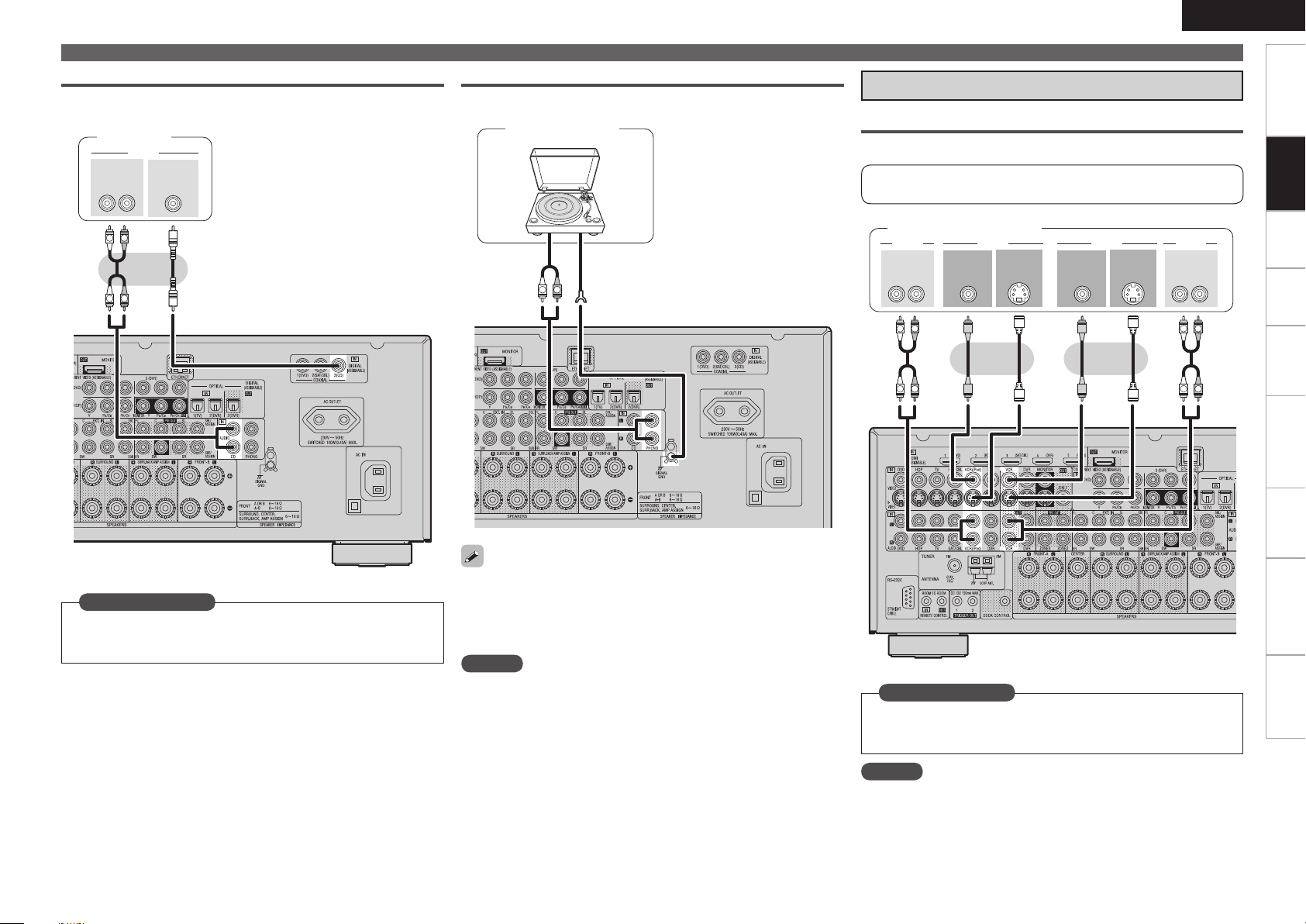
CD Player
Select the terminal to use and connect the device.
CD player
Record Player
Turntable
(MM cartridge)
Connecting Devices
Connecting the Recording Components
Video Cassette Recorder
Select the terminal to use and connect the device.
For instructions on HDMI connections, see “Connecting Devices
Equipped with HDMI Terminals” on page 14.
Video cassette recorder
ENGLISH
Getting Started Settings Playback Remote ControlMulti-zone Information Troubleshooting Specifications
Connections
Set as Necessary
Set this to change the input signal to which the input source is
assigned.
“Input Assign” (vpage 44)
The AVR-3310 is compatible with record players with an MM cartridge.
•
When you connect to a record player with an MC cartridge, use a
commercially available MC head amp or a step-up transformer.
When you increase the volume without connecting the record player,
•
there may be “booming” noise from the speakers.
NOTE
The SIGNAL GND terminal of the AVR-3310 is not a safety ground
connection. Connect it to reduce noise when noise is excessive.
Note that depending on the record player, connecting the ground line
may have the reverse effect of increasing noise. In this case, it is not
necessary to connect the ground line.
Set as Necessary
Set this to change the input signal to which the input source is
assigned.
“Input Assign” (vpage 44)
NOTE
To record video signals through the AVR-3310, use the same type
of video cable for connection between the AVR-3310 and the player
as the cable used for connection between the AVR-3310 and the
recorder.
Page 22
ENGLISH
R
L
R
L
R
L
R
L
3- 3-
065
*/
"6%*0"6%*0 7*%&07*%&0
065 */
015*$"-015*$"-
*/
"6%*0"6%*0
065
7*%&0 7*%&0
$0.10/&/57*%&0
: 1# 13
065
47*%&0
065
47*%&0
*/
R
L
R
L
3-
065
"6%*0
7*%&0
"6%*0
065
7*%&0
47*%&0
065
065
015*$"-
Getting Started Connections Settings Playback Remote ControlMulti-zone Information Troubleshooting Specifications
Connections
Connecting Devices
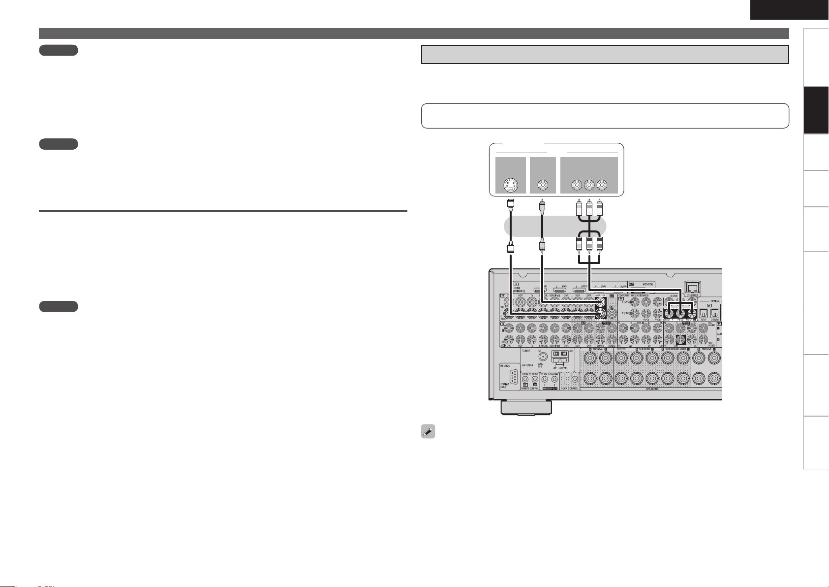
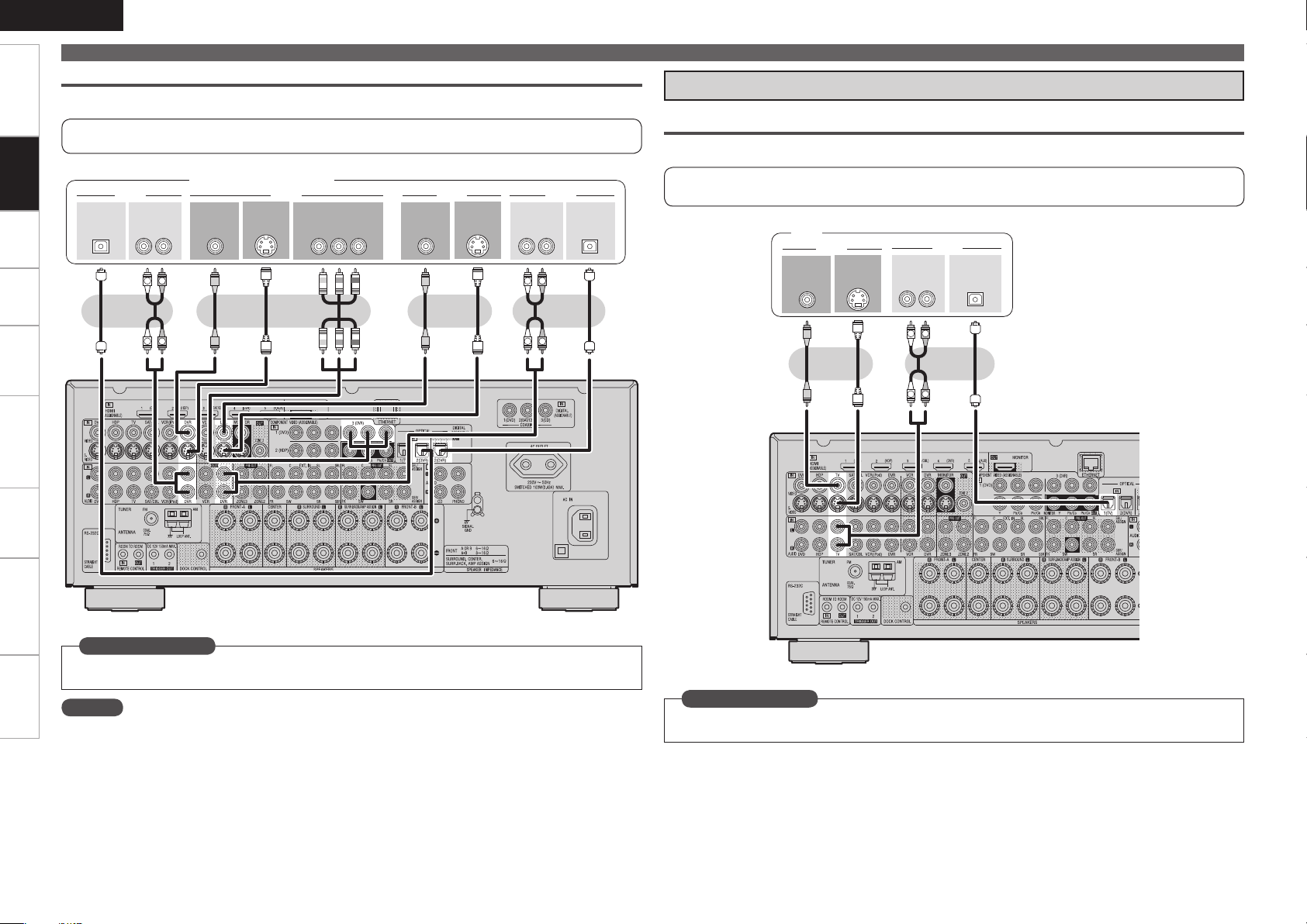
Digital Video Recorder
Select the terminal to use and connect the device.
For instructions on HDMI connections, see “Connecting Devices Equipped with HDMI Terminals” on
page 14.
Connect the Tuner
TV
Select the terminal to use and connect the device.
Digital video recorder
For instructions on HDMI connections, see “Connecting Devices Equipped with HDMI Terminals” on
page 14.
TV
Set as Necessary
Set this to change the input signal to which the input source is assigned.
“Input Assign” (vpage 44)
NOTE
To record video signals through the AVR-3310, use the same type of video cable for connection between
•
the AVR-3310 and the player as the cable used for connection between the AVR-3310 and the recorder.
Do not connect the output of the component connected to the AVR-3310’s OPTICAL2 (DVR) output
•
connector to any input connector other than OPTICAL2 (DVR).
Set as Necessary
Set this to change the input signal to which the input source is assigned.
“Input Assign” (vpage 44)
Page 23

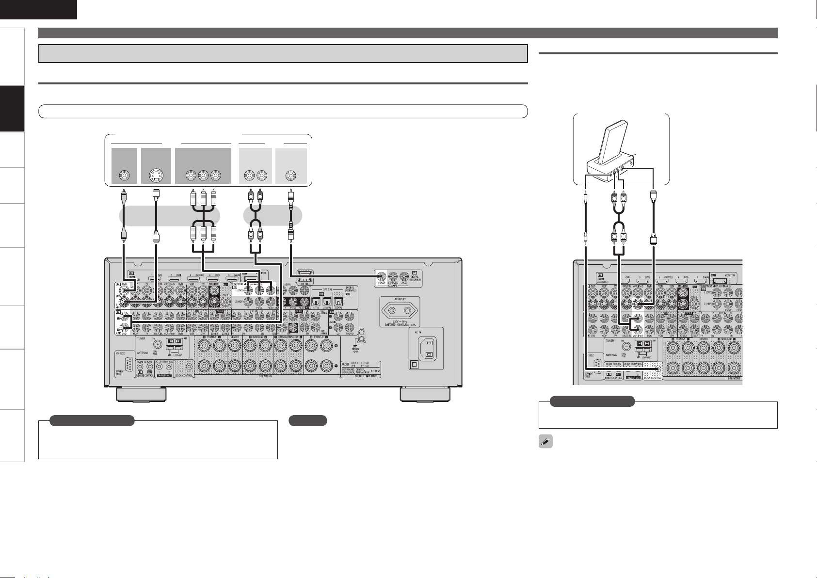
Satellite Receiver / Cable Tuner (Set Top Box)
R
L
R
L
3-
065
"6%*0
7*%&0
"6%*0
065
7*%&0
47*%&0
065
065
$0"9*"-
Select the terminal to use and connect the device.
FM/AM
An FM antenna cable plug can be connected directly.
ENGLISH
Connecting Devices
Getting Started Settings Playback Remote ControlMulti-zone Information Troubleshooting Specifications
For instructions on HDMI connections, see “Connecting Devices Equipped with HDMI Terminals” on
page 14.
Satellite Receiver / Cable Tuner
Set as Necessary
Set this to change the input signal to which the input source is assigned.
“Input Assign” (vpage 44)
Direction of broadcasting station
FM antenna
75 Ω/ohms
Coaxial cable
FM indoor antenna
(supplied)
n AM loop antenna assembly
Remove the vinyl tie and take
1
out the connection line.
Bend in the reverse direction.
2
With the antenna
-1
3
on top of any
stable surface.
With the antenna
-2
3
attached to a wall.
Mount
Installation hole Mount on wall, etc.
Connections
AM loop
antenna
(supplied)
Ground AM outdoor antenna
n Connection of AM antennas
Push the lever.
1
Insert the conductor.
2
Return the lever.
3
NOTE
• Do not connect two FM antennas simultaneously.
• Even if an external AM antenna is used, do not
disconnect the AM loop antenna.
• Make sure the AM loop antenna lead terminals do
not touch metal parts of the panel.
Page 24

ENGLISH
R
L
R
L
47*%&0
065
"6%*07*%&0
7*%&0
065 065
015*$"-"6%*0
3-
065
R
L
R
L
R
L
R
L
R
L
R
L
46#
800'&3
$&/5&3 463306/%
#"$,
3-
463306/%
3-
'30/5
3-
"6%*0
Getting Started Connections Settings Playback Remote ControlMulti-zone Information Troubleshooting Specifications
Connecting Devices
Connections to Other Devices
Video Camera / Game Console
Connections
Select the terminal to use and connect the device.
Video camera / Game console
USB Port
When you connect a USB memory device to the USB port, you can
enjoy music, etc., stored on the USB memory device.
USB memory
device
Component with Multi-channel Output connectors
The video signal can be connected in the same way as a Blu-ray Disc
player / DVD player (vpage 16 “Blu-ray Disc Player / DVD Player”).
Blu-ray Disc player / DVD player /
External decoder
Set as Necessary
Set this to change the input signal to which the input source is
assigned.
“Input Assign” (vpage 44)
0
NOTE
Do not use an extension cable when connecting a USB memory
device. This may cause radio interference with other devices.
Set as Necessary
To play analog signals input from the external input (EXT. IN)
terminal, set “Input Mode” (vpage 47) to “EXT. IN”.
“EXT. IN” can also be selected with [INPUT MODE] on the main
remote control unit.
When a device is connected to the SBL/SBR terminal of the external
input terminals (EXT. IN), set “Amp Assign” (vpage 33) to
“Normal”.
Page 25

External Power Amplifier
R
L
R
L
R
L
R
L
R
L
R
L
46#
800'&3
$&/5&3 463306/%
#"$,
3-
463306/%
3-
'30/5
3-
"6%*0
"69
065
Select the terminal to use and connect the device.
•
Connect when using an external power amp or an amp you already
•
have.
Power amplifier
External Controller
RS-232C connector
n
When you connect an external control device, you can control
the AVR-3310 with the external control device. Perform the
operation below beforehand.
q Turn on the AVR-3310’s power.
w Turn off the AVR-3310’s power from the external
controller.
e Check that the AVR-3310 is in the standby mode.
REMOTE CONTROL jacksn
Infrared
retransmitter
Infrared
sensor
Input Output
ENGLISH
Connecting Devices
Extension jack for future use.
(Connect devices corresponding
with room to room function to
this jack.)
Getting Started Settings Playback Remote ControlMulti-zone Information Troubleshooting Specifications
Connections
When using just one surround back speaker, connect it to the left
•
channel (L).
Use the volume control on the subwoofer to control subwoofer
•
volume.
If the subwoofer volume sounds low, use the volume control
•
provided on the subwoofer to adjust the volume.
NOTE
When speakers have been connected to PRE OUT terminals, do not
•
connect the speakers to the speaker terminals.
The channel output from the PRE OUT SBL and SBR terminals
•
changes depending on the “Amp Assign” setting (vpage 33).
Set as Necessary
Set this to use the RS-232C connector for the DENON RF remote
controller.
“232C Port” (vpage 42)
When using the AVR-3310 in combination with the DENON RF remote
controller (RC-7000CI, sold separately) or RF remote receiver (RC7001RCI, sold separately), two-way communication is enabled. The
AVR-3310’s status information as well as iPod and Internet audio music
files can be browsed watching the RF Remote Controller’s display. For
details, refer to the operating instructions of the respective devices.
NOTE
On the GUI menu, when setting “232C Port” to “2Way Remote”, you
cannot use the RS-232C connector as an external controller (vpage
42).
TRIGGER OUT jacks
n
The TRIGGER OUT output terminal outputs a maximum 12
V/150 mA electrical signal. When a device with TRIGGER IN
terminal is connected via a monaural mini-plug, the connected
device’s power on/standby can be controlled through linked
operation to the AVR-3310.
Set as Necessary
Set to change the conditions for linked operation via the TRIGGER
OUT 1 or TRIGGER OUT 2 terminal.
“Trigger Out1” or “Trigger Out2” (vpage 42)
When connecting a 2nd device, connect to the TRIGGER OUT 2
terminal in the same way as the TRIGGER OUT 1 terminal.
Page 26
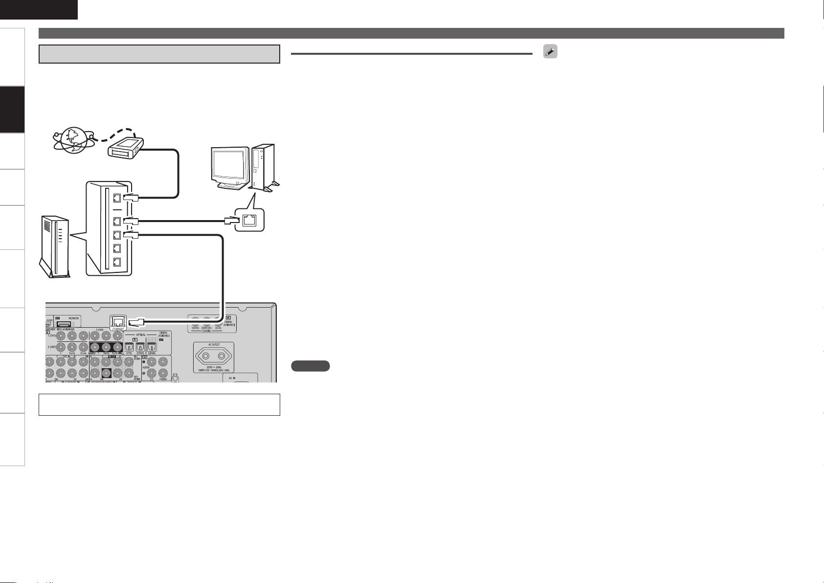
ENGLISH
Getting Started Settings Playback Remote ControlMulti-zone Information Troubleshooting Specifications
Connecting Devices
Connecting to a Home Network (LAN)
When you connect the AVR-3310 to a home network, you can enjoy
listening to music files stored on your PC, internet radio audio and
Connections
other sources. You can also control the AVR-3310 from your PC via
the Web browser.
Internet
Modem
To WAN side
To LAN port
To LAN port
Router
For connections to the Internet, contact an ISP (Internet
Service Provider) or a computer shop.
Computer
LAN port/
Ethernet
connector
Required system
Broadband Internet connection
n
Modem
n
Router
n
When using the AVR-3310, we recommend you use a router
equipped with the following functions:
Built-in DHCP server
•
This function automatically assigns IP addresses on the LAN.
Built-in 100BASE-TX switch
•
When connecting multiple devices, we recommend a switching
hub with a speed of 100 Mbps or greater.
Ethernet cable (CAT-5 or greater recommended)
n
Some flat type Ethernet cables are easily affected by noise.
We recommend using a normal type cable.
Computer
n
GRecommended systemH
OS :
•
Windows® XP Service Pack2 or later, Windows Vista
Software (Prepare one of the following.)
•
Windows Media Player ver.11
•
DLNA-compatible server software
•
Internet browser :
•
Microsoft Internet Explorer 6 or later
LAN port
•
300 MB or more free disk space
•
Operation is possible with DLNA servers other than the above,
b
but such DLNA servers are not supported. For details, check the
Web.
NOTE
A contract with an ISP is required to connect to the Internet.
•
No additional contract is needed if you already have a broadband
connection to the Internet.
The types of routers that can be used depend on the ISP. Contact an
•
ISP or a computer shop for details.
Depending on the server, video files may be displayed, but they
•
cannot be played on the AVR-3310.
If you have an Internet provider contract for a line on which network
•
settings are made manually, make the settings at “Network
Connecting” (vpage 37).
With the AVR-3310, it is possible to use the DHCP and Auto IP
•
functions to make the network settings automatically.
When using the AVR-3310 with the broadband router’s DHCP
•
function enabled, the AVR-3310 automatically performs the IP
address setting and other settings.
When using the AVR-3310 connected to a network with no DHCP
function, make the settings for the IP address, etc., at “Network
Connecting” (vpage 37).
The AVR-3310 is not compatible with PPPoE. A PPPoE-compatible
•
router is required if you have a contract for a line of the type with
which the PPPoE is set.
Depending on the ISP with which you have your contract, it may be
•
necessary to make proxy server settings to use the Internet radio
function. If you made proxy server settings on the computer to
connect to the Internet, make the proxy server settings on the AVR3310 in the same way.
Page 27
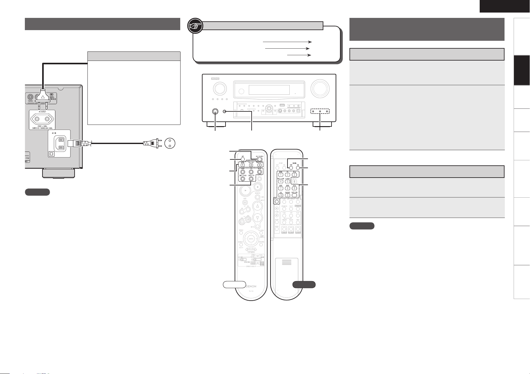
Connecting the Power Cord
[OFF]
[ON/SOURCE]
QUICK SELECT
[INPUT
SOURCE
SELECT]
QUICK SELECT<POWER><ON/STANDBY>
[MAIN OFF]
[MAIN ON]
[INPUT
SOURCE
SELECT]
Wait until all connections have been completed before connecting the
power cord.
NOTE
Insert the AC plugs securely. Incomplete connections could cause
•
noise.
Only use the AC outlet to plug in audio equipment. Do not use
•
them as power supplies for hairdryers or anything other than audio
equipment.
Connection to the AC outlet
This outlet supply power to external
•
audio equipment.
Audio equipment with a total power
•
consumption of 100 W (0.43 A) can be
connected.
The power supply turns on and off
•
together with <ON/STANDBY>. When
set to “ON”, power is supplied from
the outlet. When set to “STANDBY”,
no power is supplied.
Power cord
(included)
To household power
outlet
(AC 230 V, 50 Hz)
Symbols used to indicate buttons in this manual
Button located on both the main unit
and the remote control unit
Button only on the main unit
Button only on the remote control unit
BUTTON
<BUTTON>
[BUTTON]
ENGLISH
Once Connections are
Completed
Turning the Power On
Press <POWER>.
1
The power indicator lights red and the power is set to the
standby mode.
Press [ON/SOURCE] or <ON/STANDBY>.
2
The power indicator flashes green and the power turns on.
Also press [INPUT SOURCE SELECT] or QUICK SELECT when in
b
standby mode, the power turns on.
When [INPUT SOURCE SELECT] has been pressed, the input
source set with the [INPUT SOURCE SELECT] is set. If a QUICK
SELECT has been pressed, the input source stored in the memory
for the quick select function is set (vpage 77 “Saving Frequently
Used Settings (Quick Select Function)”).
Turning the Power Off
Press [OFF] or <ON/STANDBY>.
1
The power is set to the standby mode.
Press <POWER>.
2
The power indicator turns off, and so does the power.
NOTE
Power continues to be supplied to some of the circuitry even when
•
the power is in the standby mode. When leaving home for long
periods of time or when traveling, either press <POWER> to turn off
the power, or unplug the power cord from the power outlet.
When using ZONE2 or ZONE3, it is possible to turn the power for
•
the MAIN ZONE only on or off by pressing [MAIN ON] or [MAIN
OFF].
Getting Started Settings Playback Remote ControlMulti-zone Information Troubleshooting Specifications
Connections
Front Rear
Page 28
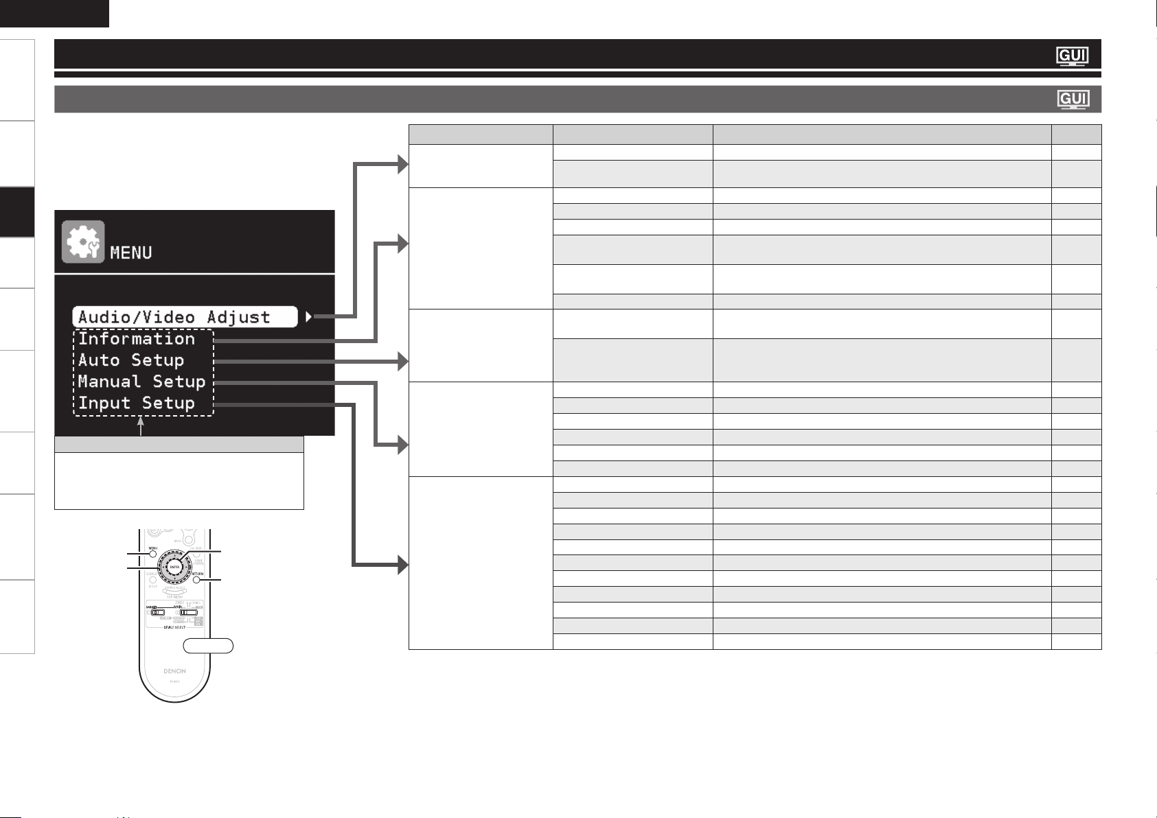
ENGLISH
RETURN
ENTER
uio p
MENU
Getting Started Connections Playback Remote ControlMulti-zone Information Troubleshooting Specifications
Settings
GUI Menu Map
Settings
Pressing MENU displays the GUI menu. From this menu, you can
move to various setting screens.
Items that only need to be set once
Set these for example upon purchase.
Once these items are set, there is no need to
set them again unless the speaker layout or the
connected speakers have been changed.
Front
Setting items Detailed items Description Page
Audio / Video Adjust
Adjust various audio and
video parameters.
Information
Show information about
receiver settings, input
signals, etc.
Auto Setup
Makes the optimum speaker
settings and corrects for the
acoustic characteristics of
the room.
Manual Setup
Use this to make various
types of detailed settings.
Input Setup
Use this to make settings
related to playing input
sources.
Audio Adjust Adjust various audio parameters. 67
Picture Adjust Adjust various video parameters. 72
Status Shows information about current settings. 73
Audio Input Signal Shows information about audio input signals. 73
HDMI Information Shows information about HDMI input/output signals and monitor. 73
Auto Surround Mode Shows information about settings stored for the auto surround
mode.
Quick Select Shows information about settings stored for the Quick Select
function.
Preset Channel Shows information about preset channels. 73
Audyssey™ Auto Setup Makes the optimum settings for the speakers being used
automatically.
Parameter Check Check Audyssey Auto Setup measurement results.
This item is only displayed after Audyssey Auto Setup procedure has
been performed.
Speaker Setup Sets the speaker size and distance, the channel level, etc. 33
HDMI Setup Make settings for HDMI video/audio output. 35
Audio Setup Make settings for audio playback. 36
Network Setup Make network settings. 37
Zone Setup Make settings for audio playback in the multi-zone system. 39
Option Setup Make various other settings. 40
Auto Preset Use the auto preset function to program radio stations. 49
Preset Skip
Preset Name Assign name to a preset memory. 49
Input Assign Change input connector assignment. 44
Video Makes the video settings. 46
Input Mode Sets the audio input mode and decode mode. 47
Rename Change the display name for this source. 48
Source Level Adjust the playback level of the audio input. 48
Playback Mode (for iPod) Make settings for “iPod” playback. 48
Playback Mode (for NET/USB) Make settings for “NET/USB” playback. 49
Still Picture Make settings for still picture playback. 49
Set the preset memories that you do not want to display when tuning.
73
73
27
32
49
Page 29

GUI Menu Operation
When a TV is connected to the AVR-3310, the GUI menu, sound field
parameters, etc., can be displayed on the TV.
This allows you to operate the AVR-3310 and make settings on it while
looking at the GUI menu displayed on the TV.
ENGLISH
Getting Started Connections Playback Remote ControlMulti-zone Information Troubleshooting Specifications
Examples of GUI Menu Screen Displays
Typical examples are described below.
Press MENU.
1
The GUI menu is displayed on the TV screen.
Press uiop to select the menu to be set or
2
operated.
To return to the previous item, press o or RETURN.b
Press RETURN to enter the setting.
3
Select “Default”, then press ENTER to reset to the default
b
setting.
Exiting the GUI Menu
n
Press MENU while the GUI menu is displayed.
The GUI menu display disappears.
Example of the Display of the GUI Mark
at a Title
Items for which this mark is indicated at the title can be
operated from the GUI.
We recommend performing such operations from the
GUI.
GExample 1H Menu selection screen GExample 2H Audyssey Auto Setup screen
(with illustration)
z1
z6
z1 : Currently selected setup item
z2 : List of currently selected setup items
z3 : Guide text for the currently selected
Press i to select “HDMI Setup”
and then press p.
(Or press ENTER.)
z2
setup item
z3
z10
z7
z9
z11
z6 : History item
z7 : Operation guidance text
z8 : Operation step
z9 : Illustration
z10 : Guide text for the currently selected
setup item
z11 : Operation button guidance
z8
Listn
Switch to the next item
(Use p or ENTER to switch.)
Settings
Making Detailed Settings
(Manual Setup)
z4
z5
z4 : History item
z5 : Currently selected setup item
Selected item
Switch the selected
b
item using ui.
Page 30

ENGLISH
Getting Started Connections Playback Remote ControlMulti-zone Information Troubleshooting Specifications
GUI Menu Operation
Selecting the Input Source
There are three ways to select the input source, as described below.
q Selecting the input source using the Source Select menu (GUI menu)
w Selecting the input source using the [INPUT SOURCE SELECT] (Main remote control unit)
e Selecting the input source using the <SOURCE SELECT> (Main unit)
q Using the Source Select Menu
Settings
The input source can also be selected using the source selection menu.
Set [DEVICE SELECT 1] to “MAIN/TV” and
1
[DEVICE SELECT 2] to “MAIN”.
Press [SOURCE SELECT].
2
Display the “Source Select” menu.
q
w
e
Front
Front
The currently selected input source
is highlighted.
“ ” is displayed when using
a control dock for iPod.
Input sources that are not going to be used can be set ahead of time. Make this setting at “Source
•
Delete” (vpage 40).
To turn off the source selection menu without selecting an input source, press [SOURCE SELECT]
•
again.
w Operating on the Main Remote Control Unit
Set [DEVICE SELECT 1] to “MAIN/TV” and [DEVICE
1
SELECT 2] to “MAIN”.
Front
Press [INPUT SOURCE SELECT].
2
The desired input source can be
selected directly.
Front Rear
e Operating on the Main Unit
Turn <SOURCE SELECT>.
b If “ZONE2/3/ Rec Select”, “Video Select” or “Tuning Preset”
mode is selected for the input source, press <SOURCE>
before turning the <SOURCE SELECT>.
q Input Source : The name of the highlighted input source is displayed.
w Recently used sources : The recently used input sources (up to 5) are displayed.
e Icons for the input sources in the different categories are displayed.
Video :
Player :
Tuner :
Network :
(SAT/CBL), (TV), (VCR), (DVR), (V.AUX)
(HDP), (DVD), (CD), (PHONO)
(FM/AM)
(Favorites), (Internet Radio), (Media Server), (USB), (Napster)
Use uio p to select the input source icon, then press ENTER.
3
The input source is set and the source selection menu is turned off.
Page 31

FL SW C FR
SL SR
SBRSBL
*
M
FL SW C FR
SL SR
SBRSBL
*
M
Make the Optimal Speaker Settings, and Correct the Room Acoustics
FHL FL SW C FR FHR
SL SR
*
M
FHL FL SW C FR FHR
SL SR
*
M
(Audyssey™ Auto Setup)
The acoustic characteristics of the connected speakers and
listening room are measured and the optimum settings are made
automatically.
Audyssey Auto Setup Flown
a Connect the Included Setup Microphone
(vpage 28)
s Audyssey Auto Setup Preparations
(vpage 29)
Change the Amplifier Assignment (Amp Assign)
n
(vpage 29)
Set the channel to be measured (Channel Select)
n
(vpage 29)
d Perform Audyssey Auto Setup (vpage 29)
Check the Measuring Results and Equalizer
Type after Audyssey Auto Setup
(Parameter Check) (vpage 32)
Important Information
Audyssey MultEQ® automatically measures the acoustical problems
in the listening environment to create the best audio experience for
your home theater.
• When Audyssey™ Auto Setup procedure is performed, the MultEQ®,
Dynamic EQ™ and Dynamic Volume™ functions (vpage 69, 70)
are enabled.
• Use the included setup microphone (DM-A409) to perform Audyssey
Auto Setup procedure.
• Measurements are performed by placing the calibrated microphone
successively at multiple positions throughout the listening area as
shown in GExample qH. For best results, it is strongly recommended
to measure 6 positions so that the measurements have the proper
spatial weighting.
Even if the listening environment is small as shown in GExample wH,
measuring at multiple points throughout the listening environment
results in more effective correction.
n When using Front Height Speakers
GExample qH GExample wH
( : Measuring positions)
ENGLISH
n When using Surround Back Speakers
GExample qH GExample wH
( : Measuring positions)
FL :
Front speaker (L)
FR : Front speaker (R)
FHL : Front height speaker (L)
FHR : Front height speaker (R)
C : Center speaker
SW : Subwoofer
SL : Surround speaker (L)
SR : Surround speaker (R)
SBL : Surround back speaker (L)
SBR : Surround back speaker (R)
About the main listening position (*M)
The main listening position refers to the most central position where
one would normally sit within the listening environment.
MultEQ uses the measurements from this position to calculate
speaker distance, level, polarity, and the optimum crossover value
for the subwoofer.
Getting Started Connections Playback Remote ControlMulti-zone Information Troubleshooting Specifications
Settings
See overleaf
Page 32
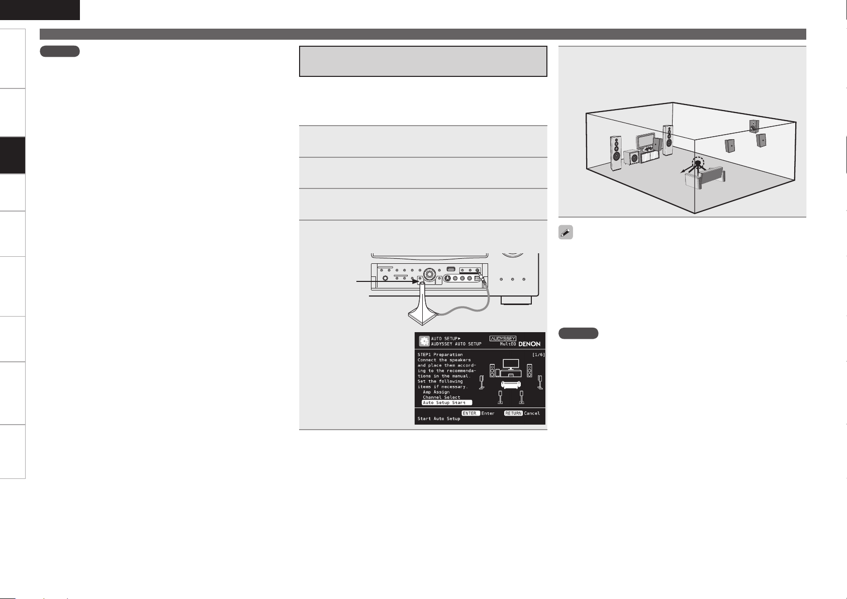
ENGLISH
Getting Started Connections Playback Remote ControlMulti-zone Information Troubleshooting Specifications
Make the Optimal Speaker Settings, and Correct the Room Acoustics (Audyssey™ Auto Setup)
NOTE
• Loud test sounds may be played during Audyssey MultEQ automatic
speaker setup. This is part of normal operation. If there is background
noise in room, these test signals will increase in volume.
• Do not stand between the speakers and setup microphone or allow
obstacles in the path while the measurements are being made. This
will cause inaccurate readings.
• Make the room as quiet as possible. Background noise can disrupt
Settings
the room measurements. Close windows, silence cell phones,
televisions, radios, air conditioners, fluorescent lights, home
appliances, light dimmers, or other devices as measurements may
be affected by these sounds.
Cell phones should be placed away from all audio electronics during
the measurement process as Radio Frequency Interference (RFI)
may cause measurement disruptions (even if the cell phone is not in
use).
Operating MASTER VOLUME during the measurements will cancel
•
the measurements.
a Connect the Included Setup
Microphone
Do not remove the setup microphone until Audyssey Auto Setup is
•
completed.
When using headphones, unplug the headphones before starting
•
Audyssey Auto Setup procedure.
Check the speaker connections.
(vpage 13 “Speaker Connections”)
1
Turn on the TV and subwoofer power.
Change the TV input to AVR-3310 input.
2
Turn on the AVR-3310 power.
(vpage 23 “Turning the Power On”)
3
Connect the setup microphone to the SETUP MIC
4
jack of the AVR-3310.
Sound
receptor
“Audyssey Auto Setup”
screen is displayed when
you connect the setup
microphone.
Mount the setup microphone on a tripod or stand
5
and place it in the main listening position.
When placing the setup microphone, adjust the height of the
sound receiver part to the level of the listener’s ear.
Setup
microphone
If you subwoofer provides volume and crossover settings, set these
as shown below before starting Audyssey Auto Setup.
Volume setting : “12 o’clock” position” or the middle of the gain
•
knob’s range.
Low Pass Filter setting : Low Pass Filter Setting to “Off”, or
•
“Maximum/Highest Frequency”.
Phase setting : 0°
•
Standby mode setting : “Off”
•
NOTE
Do not hold the microphone in your hand during measurements.
•
Avoid placing the microphone close to a seat back or wall as sound
•
reflections may give inaccurate results.
Page 33
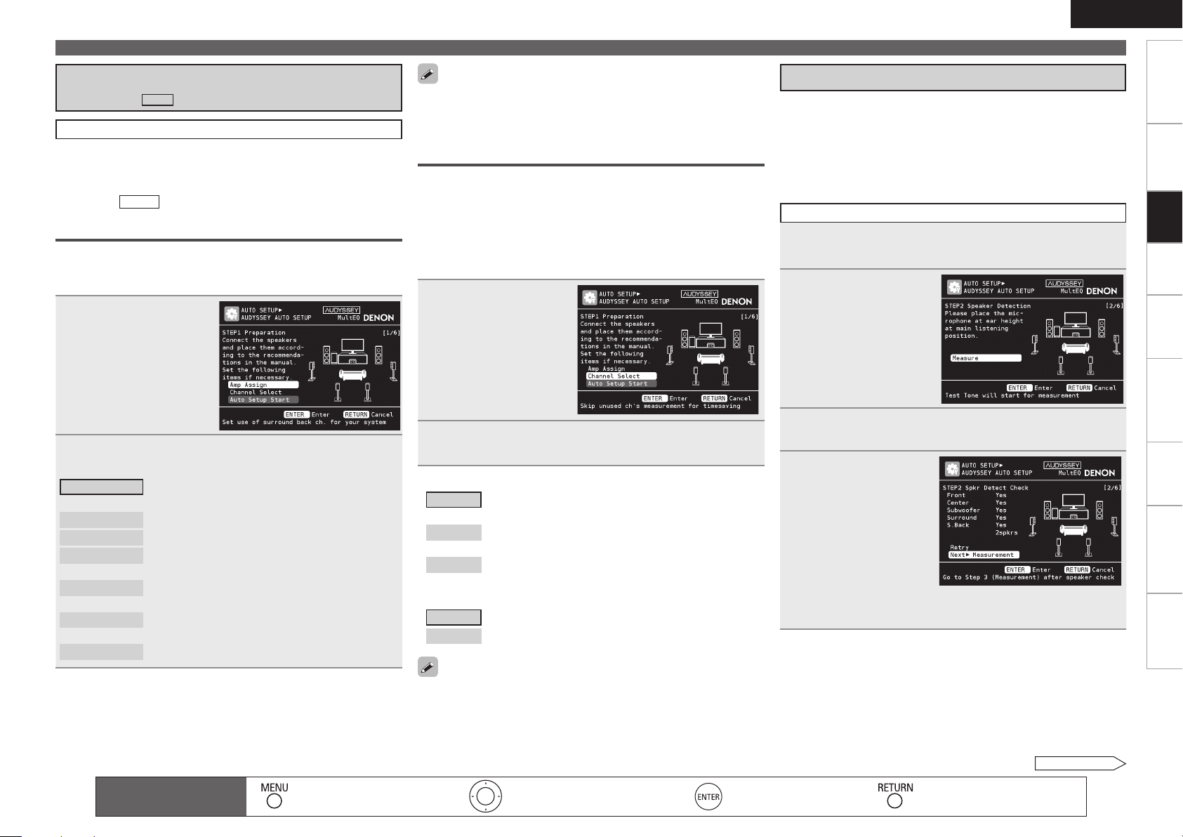
ENGLISH
Make the Optimal Speaker Settings, and Correct the Room Acoustics (Audyssey™ Auto Setup)
Getting Started Connections Playback Remote ControlMulti-zone Information Troubleshooting Specifications
s Audyssey Auto Setup Preparations
around items indicate the default setting.
STEP1 Preparation
Perform the following settings if adjustments, etc., are required for
the speaker environment you’re using.
If you do not need to perform the following settings, or have already
completed them, select “Auto Setup Start” and then press ENTER.
Proceed to “
Change the Amplifier Assignment (Amp Assign)
The signal output from the SURR.BACK/AMP ASSIGN speaker terminal
of the AVR-3310 can be switched to match your speaker environment
(vpage 33 “Amp Assign”).
1
2
ZONE2/3-MONO
Front A Bi-Amp
Front B Bi-Amp
Front Height
STEP2
”.
Press ui to select
“Amp Assign”, then
press ENTER.
Press o p to select Amp Assign Mode, then press
RETURN.
Normal
ZONE2
ZONE3
: The surround back channel audio signals are
output.
: The ZONE2 audio signals are output.
: The ZONE3 audio signals are output.
: The ZONE2 / ZONE3 monaural audio signals are
output.
: The bi-amp audio signals are output. Set this for
bi-amp playback of the front A speakers.
: The bi-amp audio signals are output. Set this for
bi-amp playback of the front A speakers.
: The front height channel audio signals are output.
When you are using surround back speakers with ZONE2/ZONE3,
•
set to “ZONE2” or “ZONE3”.
You can set in the same way as described in “Amp Assign” on page
•
33.
Set the channel to be measured (Channel Select)
Front
•
The front speaker to be measured can be selected ahead of time here.
Subwoofer, Surround Back
•
If you set the channels you will not use beforehand, those channels
will not be measured. Therefore, you can save an amount of time
commensurate with that which would have been taken to measure
those channels.
Press ui to select
1
“Channel Select”,
then press ENTER.
Press ui to select a channel, press o p to select
2
the item, and then press RETURN.
Frontn
A
: The sound is output from front speakers A when
measuring the front speakers.
: The sound is output from front speakers B when
B
measuring the front speakers.
:
A +B
The sound is output simultaneously from front speakers
A and B when measuring the front speakers.
Subwoofer, Surround Backn
Measure
: Measure the selected channel.
: Skip the selected channel and do not measure.
Skip
d Perform Audyssey Auto Setup
Audyssey Auto Setup detects the presence of each speaker and
•
automatically calculates the speaker size, channel level, distance and
crossover frequency settings. In addition, acoustical distortions are
corrected within the listening area.
When measuring begins, a test tone is output from each speaker.
•
Position and connect all speakers before commencing Audyssey
•
Auto Setup.
STEP2 Speaker Detection
Press ui to select “Auto Setup Start”, then press
1
ENTER.
Select “Measure”
2
and then press
ENTER.
Once all the speakers have been detected, check the
3
results of detection of the connected speakers.
Press ui to
4
select “Next 1
Measurement”, then
press ENTER.
Press u to select “Retry”, and when you press ENTER, measuring
b
at the main listening position starts again.
Settings
Main remote control
operation buttons
:Displaying the menu
Cancel the menu
When “Amp Assign” is set to “Normal”, only then is “Surround Back”
displayed.
:Moves the cursor
(Up/Down/Left/Right)
:Confirm the setting :Return to previous menu
See overleaf
Page 34
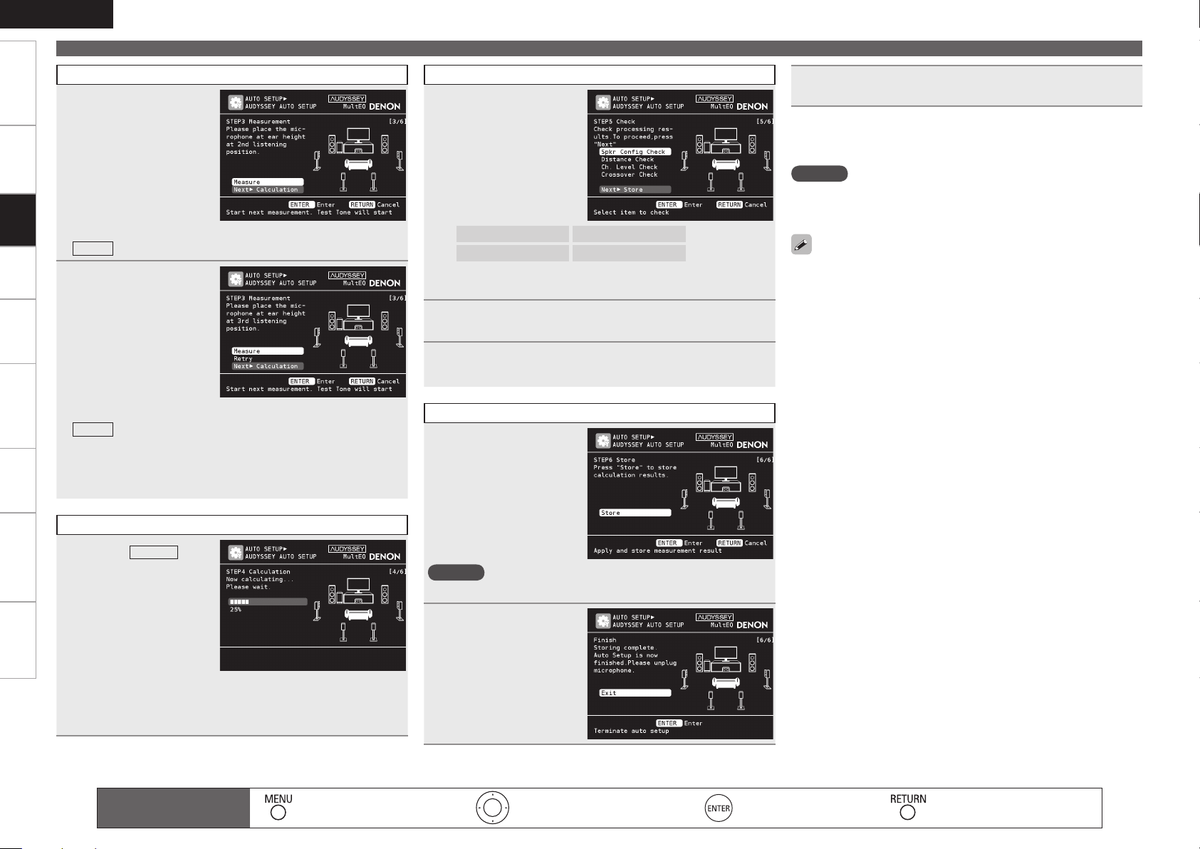
ENGLISH
Getting Started Connections Playback Remote ControlMulti-zone Information Troubleshooting Specifications
Make the Optimal Speaker Settings, and Correct the Room Acoustics (Audyssey™ Auto Setup)
STEP3 Measurement
Move the setup
5
microphone to
the 2nd position,
use ui to select
“Measure”, then
press ENTER.
Settings
Measurements for the
2nd position begin.
To skip this step, select “Next 1 Calculation” and proceed to
b
STEP4
.
Perform Step 5
6
repeatedly for the
3rd, 4th, 5th, and 6th
measurements.
When measurements
of the 6th position
are completed,
“Measurements
finished.” is displayed.
To skip this step, select “Next 1 Calculation” and proceed to
b
STEP4
.
Measure at a total of 6 positions, including the main listening
b
position and positions around it. It is possible to stop the settings
with five positions or fewer, but for better results we recommend
measuring at 6 positions.
STEP5 Check
Use ui to select
8
the item you want
to check, then press
ENTER.
The measurement result
confirmation screen is
displayed.
Speaker Config. Check Distance Check
Channel Level Check Crossover Freq. Check
Subwoofer or other speakers may be set to a value that does not
b
correspond to the actual distance.
Press RETURN.
9
If you want to check another item, so repeat step 8.
Press i to select “Next 1 Store”, then press
10
ENTER.
STEP6 Store
Select “Store” then
11
press ENTER.
“Now Storing... Please
wait.” is displayed while
the results are being
stored.
Select “Exit” and then press ENTER.
13
Exiting the GUI Menu
n
Press MENU while the GUI menu is displayed.
The GUI menu display disappears.
NOTE
After performing Audyssey Auto Setup, do not change the speaker
connections or subwoofer volume. In event of a change, perform
Audyssey™ Auto Setup again.
If there is a disparity between the results and the connection status,
•
or if an error message is displayed, check the error message against
the errors listed in the “Error Messages” section (vpage 31) and
perform Audyssey Auto Setup again.
If the result still differs from the actual connection status after
•
remeasurement or the error message still appears, it is possible
that the speakers are not connected properly. Turn the AVR-3310
off, check the speaker connections and repeat the measurement
process from the beginning. Turn the AVR-3310 off, check the
speaker connections and repeat the measurement process from the
beginning.
If you change a speaker position or orientation, perform Audyssey
•
Auto Setup again to obtain optimal equalizer correction.
STEP4 Calculation
On the
7
screen, use ui
STEP3
to select “Next 1
Calculation”, then
press ENTER.
Analysis begins.
Analysis takes several minutes to complete.
b
The time required for this analysis depends on the number
of speakers connected. The greater the number of speakers
connected, the longer analysis will take.
0
Main remote control
operation buttons
:Displaying the menu
Cancel the menu
NOTE
Do not turn the power off while the settings are being stored.
When the screen
12
shown on the right
appears, unplug the
setup microphone
from the AVR-3310
SETUP MIC jack.
:Moves the cursor
(Up/Down/Left/Right)
:Confirm the setting :Return to previous menu
Page 35
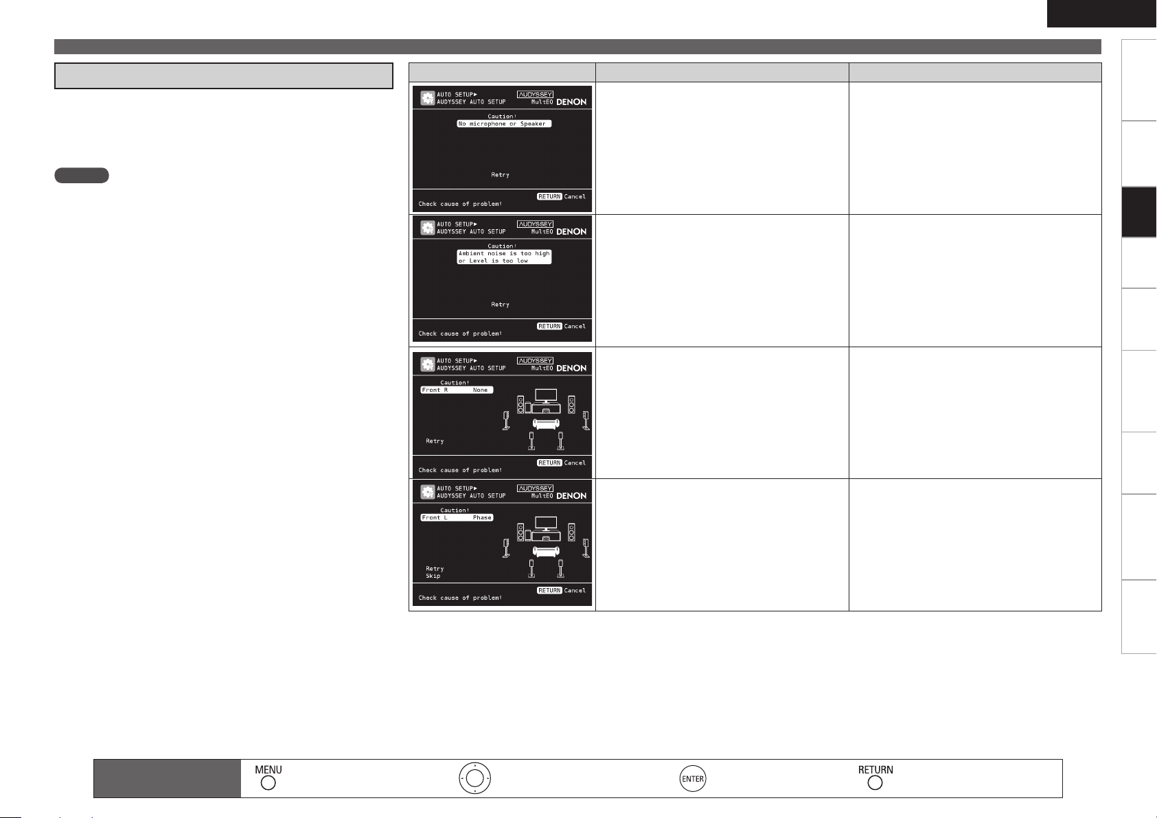
ENGLISH
Make the Optimal Speaker Settings, and Correct the Room Acoustics (Audyssey™ Auto Setup)
Getting Started Connections Playback Remote ControlMulti-zone Information Troubleshooting Specifications
Error Messages
An error message is displayed if it was not possible to complete
Audyssey Auto Setup due to speaker placement, the measurement
environment, etc. If this happens, check the relevant items, be sure
to take the necessary measures, then perform Audyssey Auto Setup
procedure over again.
NOTE
Be sure to turn off the power before checking speaker connections.
When Performing Audyssey Auto Setup Over
n
Again
Press ui to select “Retry”, and then press ENTER.
When Measuring has Stopped
n
Press RETURN, the “Cancel auto setup?” prompt is displayed.
Press o p and select “Yes”, then press ENTER.
Error messages (examples) Error contents
Included setup microphone is not connected.
•
Not all speakers could be detected.
•
The front L speaker was not properly detected.
•
Too much noise in the room for accurate
•
measurements to be made.
Speaker or subwoofer sound is too low for
•
accurate measurements to be made.
Displayed speaker could not be detected.• Check the connections of the displayed speaker.•
Measures
Connect the included setup microphone to the
•
SETUP MIC jack of the AVR-3310.
Check the speaker connections.
•
Either turn off any device generating noise or
•
move it away.
Perform again when the surroundings are
•
quieter.
Check the speaker installation and the direction in
•
which the speakers are facing.
Adjust the subwoofer’s volume.
•
Settings
Main remote control
operation buttons
:Displaying the menu
Cancel the menu
:Moves the cursor
(Up/Down/Left/Right)
Displayed speaker connected with the polarities
• Check the polarities of the displayed speaker.
reversed.
•
For some speakers, this error message may
•
be displayed even if the speaker is properly
connected. If you are sure the connection is
correct, press ui to select “Skip”, then press
ENTER.
:Confirm the setting :Return to previous menu
Page 36
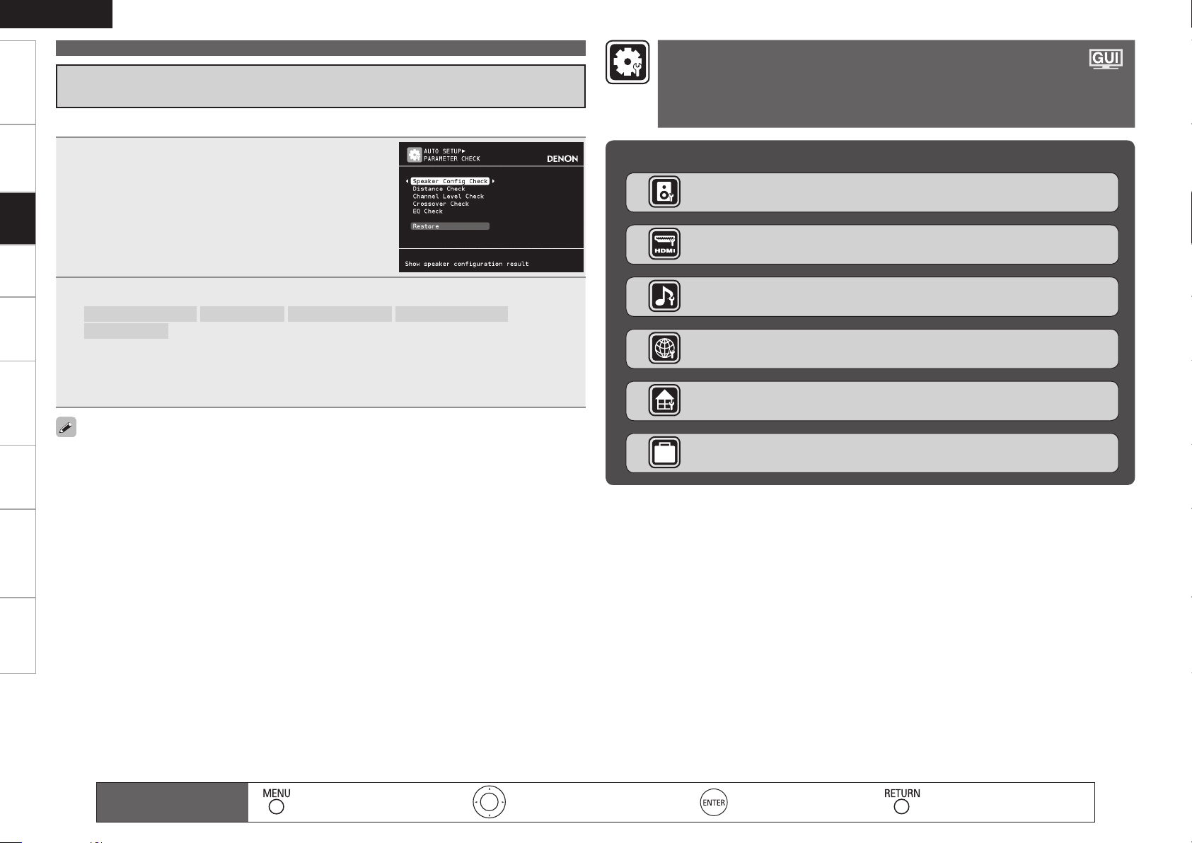
ENGLISH
OPTION
Getting Started Connections Playback Remote ControlMulti-zone Information Troubleshooting Specifications
Make the Optimal Speaker Settings, and Correct the Room Acoustics (Audyssey™ Auto Setup)
Check the Measuring Results and Equalizer Type after
Audyssey Auto Setup (Parameter Check)
This is displayed after Audyssey Auto Setup procedure is completed.
Making Detailed Settings
(Manual Setup)
For details on how to select, set and cancel settings for each menu, see “GUI Menu
Operation” (vpage 25).
Press i to select “Parameter Check”, and then
1
press ENTER or p.
Settings
Press ui to select the item you want to check, and then press ENTER or p.
2
Speaker Config. Check Distance Check Channel Level Check Crossover Freq. Check
EQ Check
The measurement result of each speaker is displayed.
When you selected “EQ Check”, press ui to select the Correction curve you want to check
b
(“Audyssey” or “Audyssey Flat”).
When you want to check another item, press RETURN.
b
If you set “Restore” to “Yes”, you can return to Audyssey Auto Setup measurement result (value calculated
at the start by MultEQ) even when you have changed each setting manually.
Items that can be set with the Manual Setup proceduren
Making the speaker settings (Speaker Setup) vpage 33
Making the HDMI settings (HDMI Setup) vpage 35
Making the audio settings (Audio Setup) vpage 36
Making the network settings (Network Setup) vpage 37
Making the Multi-zone settings (Zone Setup) vpage 39
Making other settings (Option Setup) vpage 40
Main remote control
operation buttons
:Displaying the menu
Cancel the menu
:Moves the cursor
(Up/Down/Left/Right)
:Confirm the setting :Return to previous menu
Page 37
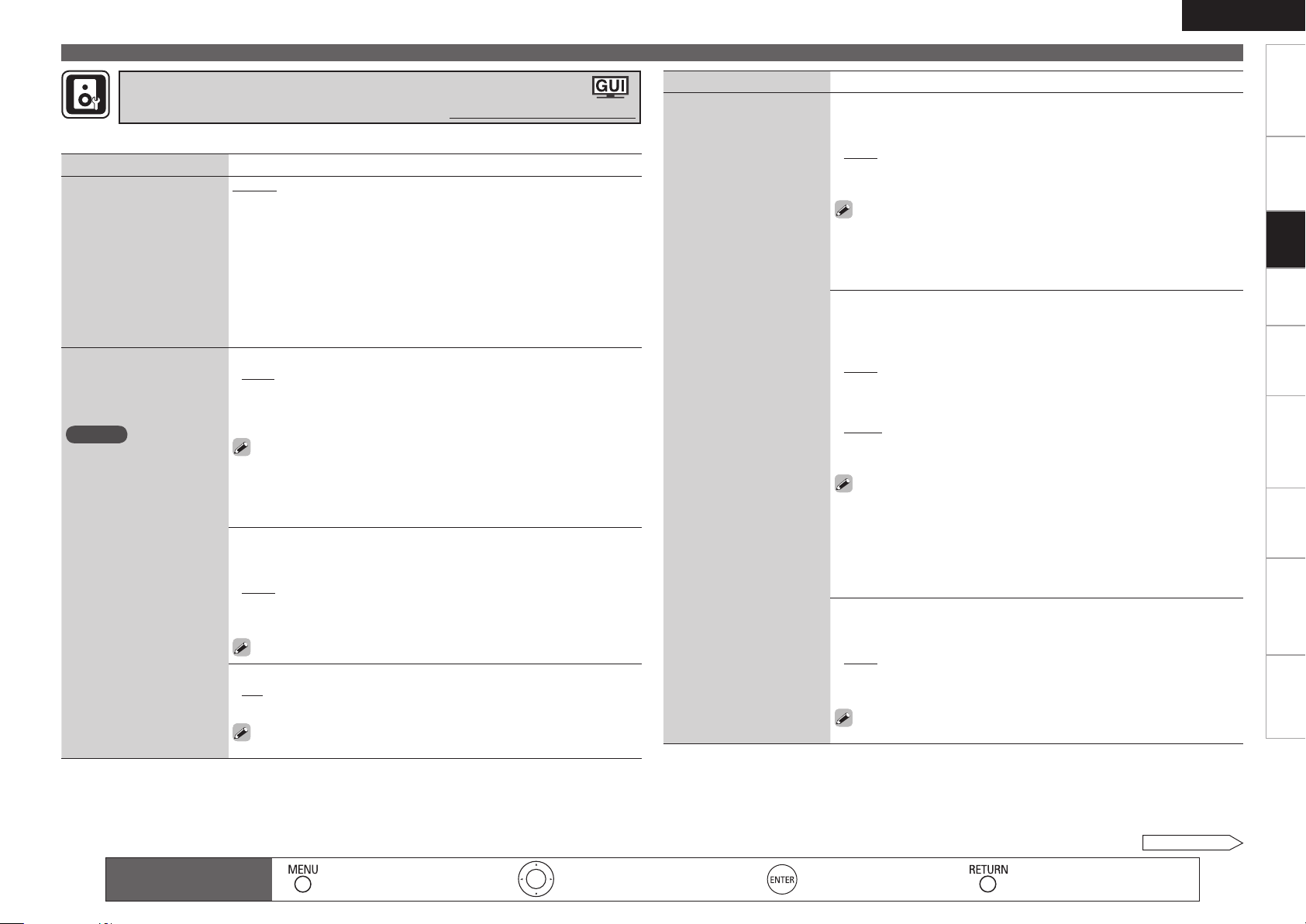
ENGLISH
Making Detailed Settings (Manual Setup)
Getting Started Connections Playback Remote ControlMulti-zone Information Troubleshooting Specifications
Making the Speaker Settings (Speaker Setup)
Default settings are underlined.
Perform when setting the speakers manually or when changing settings made in Audyssey Auto Setup.
Setting items Setting contents
Amp Assign
Sets the signal output to the
speaker connected to the
SURR. BACK/AMP ASSIGN
terminals.
Speaker Configuration
Select speaker configuration
and size (bass reproduction
capability).
NOTE
Select “Large” or “Small”
not according to the
physical size of the speaker
but according to the low
frequency reproduction
capabilities based on the
frequency set at “Crossover
Frequency” (vpage 35).
Normal : The surround back channel audio signals are output.
ZONE2 : The ZONE2 audio signals are output.
ZONE3 : The ZONE3 audio signals are output.
ZONE2/3-MONO : The ZONE2 / ZONE3 monaural audio signals are
output.
Front A Bi-Amp : The bi-amp audio signals are output. Set this for bi-amp
playback of the front A speakers.
Front B Bi-Amp : The bi-amp audio signals are output. Set this for bi-amp
playback of the front B speakers.
Front Height : The front height channel audio signals are output.
Front : Set the front speaker size.
Large : Use of a large speaker that can adequately playback low
•
frequencies.
Small : Use of a small speaker that has inadequate playback capacity for
•
low frequencies.
When “Subwoofer” is set to “No”, “Front” can automatically set to
•
“Large”.
When “Front” is set to “Small”, “Center”, “Surround“, “Surround
•
Back” and “Front Height” can not be set to “Large”.
Center : Set the presence and size of the center speaker.
Large : Use of a large speaker that can adequately playback low
•
frequencies.
Small : Use of a small speaker that has inadequate playback capacity for
•
low frequencies.
None : Select when a center speaker is not connected.
•
“Large” is not displayed when “Front” is set to “Small”.
Subwoofer : Set the presence of a subwoofer.
Yes : Use a subwoofer.
•
No : Select when a subwoofer is not connected.
•
When “Front” is set to “Small”, “Subwoofer” can automatically set
to “Yes”.
Setting items Setting contents
Speaker Configuration
(Continued)
Surround : Set the presence and size of the surround speakers.
Large : Use of a large speaker that can adequately playback low
•
frequencies.
Small : Use of a small speaker that has inadequate playback capacity for
•
low frequencies.
None : Select when the surround speakers A are not connected.
•
When “Surround” is set to “Large”, “Front Height” can be set to
•
“Large”.
When “Surround” is set to “None”, “Surround Back” and “Front Height”
•
can automatically set to “None”.
Surround Back : Set the presence, size and number of surround back
speakers.
Large : Use of a large speaker that can adequately playback low
•
frequencies.
Small : Use of a small speaker that has inadequate playback capacity for
•
low frequencies.
None : Select when the surround back speakers are not connected.
•
2spkrs : Use two surround back speakers.
•
1spkr : Use only one surround back speaker. When you select this
•
setting, connect the surround back speaker to the left (L) channel.
When the “Amp Assign” setting (vpage 33) is other than “Normal”,
•
you cannot make the “Surround Back” setting.
Even when the Surround Back Speaker setting is other than “None”,
•
sound may not be emitted from the surround back speaker, depending
on the playback source. In this case, “Surround Parameters” – “Surround
Back” setting other than “OFF” (vpage 68).
Front Height : Set the presence and size of the front height speakers.
Large : Use of a large speaker that can adequately playback low
•
frequencies.
Small : Use of a small speaker that has inadequate playback capacity for
•
low frequencies.
None : Select when the front height speakers are not connected.
•
When the “Amp Assign” setting (vpage 33) is other than “Front
Height”, you cannot make the “Front Height” setting.
Settings
Main remote control
operation buttons
:Displaying the menu
Cancel the menu
:Moves the cursor
(Up/Down/Left/Right)
:Confirm the setting :Return to previous menu
See overleaf
Page 38
ENGLISH
Getting Started Connections Playback Remote ControlMulti-zone Information Troubleshooting Specifications
Making Detailed Settings (Manual Setup)
Setting items Setting contents
Bass Setting
Settings for subwoofer and
LFE signal range playback.
Settings
Distance
Set distance from listening
position to speakers.
Measure beforehand the
distance from the listening
position to each speaker.
Subwoofer Mode : Select low range signals to be reproduced by
subwoofer.
LFE : The low range signal of the channel set to “Small” speaker size is
•
added to the LFE signal output from the subwoofer.
LFE+Main : The low range signal of all channels is added to the LFE
•
signal output from the subwoofer.
This can be set when “Speaker Configuration” – “Subwoofer” (vpage
•
33) is set to “Yes”.
Play music or a movie source and select the mode offering the strongest
•
bass.
Select “LFE+Main” if you want the bass signals to always be produced
•
from the subwoofer.
LPF for LFE : Set LFE signal playback range.
80Hz / 90Hz / 100Hz / 110Hz / 120Hz / 150Hz / 200Hz / 250Hz•
Unit : Set the unit of distance.
Feet
•
Meters
•
Step : Set the minimum variable width of the distance.
0.1m / 0.01m
•
1ft / 0.1ft
•
Front L / Front R / Center / Subwoofer / Surround L / Surround R /
S. Back Lz / S. Back Rz / Front Height L / Front Height R : Select the
speaker.
z: When the “Speaker Configuration” – “Surround Back” setting
(vpage 33) is set to “1spkr”, “S. Back” is displayed.
0.00m ~ 18.00m / 0.0ft ~ 60.0ft : Set the distance.
•
Setting items Setting contents
Distance
(Continued)
Channel Level
Set the volume of the test
tone to be the same when it
is output from each speaker.
Default : Reset all distance settings to factory default.
Yes : Reset to the defaults.
•
No : Do not reset to the defaults.
•
When you select “Default” and press ENTER, the “Default Setting?”
prompt is displayed. Select either “Yes” or “No”, and press ENTER.
Test Tone Start : Output test tone.
Front L / Front Height L / Center / Front Height R / Front R / Surround
•
R / S. Back Rz / S. Back Lz / Surround L / Subwoofer : Select the
speaker.
z
: When the “Speaker Configuration” – “Surround Back” setting
(vpage 33) is set to “1spkr”, “S. Back” is displayed.
–12.0dB ~ +12.0dB (0.0dB) : Adjust the volume.
•
Speakers set to “None” in the “Speaker Configuration” (vpage 33)
•
settings are not displayed.
When o is pressed while the subwoofer volume is set to “–12 dB”, the
•
“Subwoofer” setting switches to “OFF”.
When a headphones jack is inserted in the PHONES terminal of the AVR-
•
3310, the “Channel Level” is not displayed.
You can also press [CHANNEL LEVEL] to set (vpage 76 “Adjust the
•
Volume of the Different Speakers“).
Default : Reset all channel level settings to factory default.
Yes : Reset to the defaults.
•
No : Do not reset to the defaults.
•
•
•
•
•
Main remote control
operation buttons
Speakers set to “None” in “Speaker Configuration” (vpage 33) are
not displayed.
The speakers that can be selected differ depending on the “Amp Assign”
(vpage 33) and “Speaker Configuration” (vpage 33) settings.
Default settings :
Front / Center / Subwoofer / Front Height : 3.60 m (12.0 ft)
Surround / Surround Back : 3.00 m (10.0 ft)
Set the difference in the distance between the speakers to less than 6.0
meters (20 feet).
:Displaying the menu
Cancel the menu
:Moves the cursor
(Up/Down/Left/Right)
:Confirm the setting :Return to previous menu
Page 39
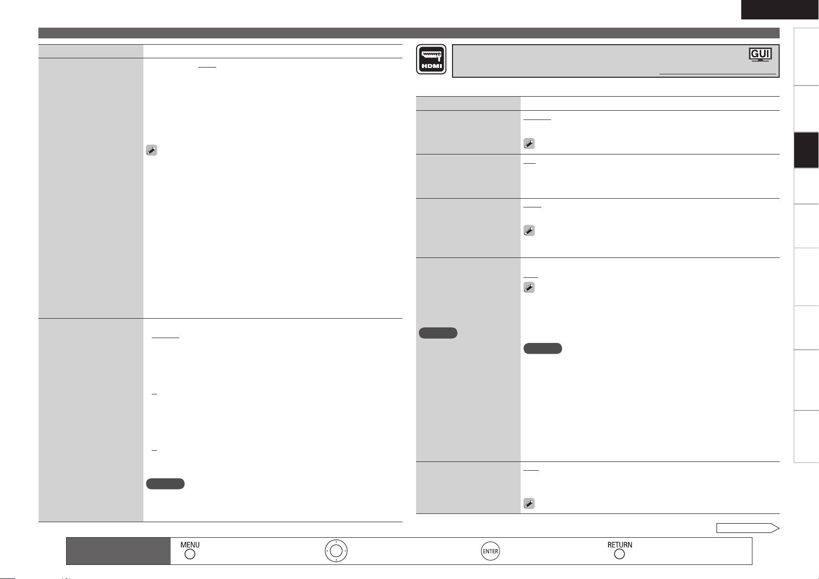
ENGLISH
Making Detailed Settings (Manual Setup)
Getting Started Connections Playback Remote ControlMulti-zone Information Troubleshooting Specifications
Setting items Setting contents
Crossover Frequency
Outputs at below set
frequency, each speaker’s
bass signal output from
the subwoofer. Set this
according to the low
frequency reproduction
capabilities of the speakers
you are using.
Front Speaker Setup
Set the front speakers to use
for every surround mode.
40Hz / 60Hz / 80Hz / 90Hz / 100Hz / 110Hz / 120Hz / 150Hz / 200Hz /
250Hz : Set the crossover frequency.
Advanced : Specify crossover frequency for each speaker.
Front / Center / Surround / Surround Back / Front Height : Select the
•
speaker.
40Hz / 60Hz / 80Hz / 90Hz / 100Hz / 110Hz / 120Hz /150Hz / 200Hz /
•
250Hz : Set the crossover frequency.
Can be set when the “Speaker Configuration” – “Subwoofer” (vpage
•
33) setting is “Yes”, or when you have a speaker that is set to “Small”.
Always set the crossover frequency to “80 Hz”. When using small
•
speakers, however, we recommend setting the crossover frequency to
a higher frequency.
For speakers set to “Small”, sound below the crossover frequency is cut
•
from the sound output. The cut bass sound is output from the subwoofer
or front speakers.
The speakers that can be set when “Advanced” is selected differ
•
according to the “Subwoofer Mode” setting (vpage 34).
When “LFE” is selected, speakers set to “Small” at “Speaker
•
Configuration” can be set. If the speakers are set to “Large”, “Full
Band” is displayed and the setting cannot be made.
If set to “LFE+Main”, this setting can be made regardless of the
•
speaker size.
Setting : Choose the method for setting the front speakers.
Normal : The front speakers are set using the <FRONT SPEAKERS>.
•
Custom : The front speakers used for the different playing modes are
•
set in advance.
2CH DIRECT/STEREO : The front speakers used in the direct, stereo and
pure direct play modes (2 channel) are set in advance.
A : Front speaker A is used.
•
B : Front speaker B is used.
•
A+B : Both front speakers A and B are used.
•
MULTI CH : The front speakers used in modes other than the direct, stereo and pure direct play modes (2 channel) are set in advance.
A : Front speaker A is used.
•
B : Front speaker B is used.
•
A+B : Both front speakers A and B are used.
•
NOTE
• When set to “Custom”, <FRONT SPEAKERS> does not operate.
• The front speaker setting stored for the “Quick Select” function is given
priority.
Making the HDMI Settings (HDMI Setup)
Make settings for HDMI video/audio output.
Setting items Setting contents
RGB Range
Set the video range of RGB
output from the HDMI
terminal.
Auto Lip Sync
Automatic compensation
for timing shift in audio and
video output.
Audio Out
Select HDMI audio output
device.
HDMI Control
External devices can be controlled from the AVR-3310
and the AVR-3310 can be
controlled from external devices.
NOTE
The HDMI control function
controls operations of a
TV that is compatible with
the HDMI control function.
Make sure that the TV and
HDMI are connected when
you perform HDMI control.
Standby Source
Set the HDMI connector for
HDMI signal input during
standby.
Normal : Output with RGB video range (16 (black) to 235 (white)).
Enhanced : Output with RGB video range (0 (black) to 255 (white)).
This setting is valid when using a TV equipped with a DVI terminal.
ON : Compensated.
OFF : Not compensated.
AMP : Playback through speakers connected to the receiver.
TV : Playback through TV connected to the receiver.
When the HDMI control function is operating, the setting of audio
playback in the connected TV takes priority (vpage 75 “HDMI
Control Function”).
ON : Use the HDMI control function.
OFF : Do not use the HDMI control function.
Please consult the operating instructions for each connected device to
•
check the settings.
For details on the HDMI control function, see “HDMI Control Function”
•
(vpage 75).
NOTE
• When “HDMI Control” is set to “ON”, it consumes more standby
power.
• When not using this unit for a long period, we recommend that you
press <POWER> to turn off (jOFF) the power.
• When the “HDMI Control” setting has been changed, always turn off
the power to the connecting devices afterwards and then turn back on.
• The “HDMI Control” does not work when the power to the equipment
is off.
• When “HDMI Control” is set to “ON”, power is supplied constantly to
the AC outlet (UNSWITCHED).
Last : Standby with last used input source during power on.
HDMI1 / HDMI2 / HDMI3 / HDMI4 / HDMI5 : The standby mode is set at
the input source assigned to the respective.
This can be set when “HDMI Control” is set to “ON”.
Default settings are underlined.
Settings
See overleaf
Main remote control
operation buttons
:Displaying the menu
Cancel the menu
:Moves the cursor
(Up/Down/Left/Right)
:Confirm the setting :Return to previous menu
Page 40
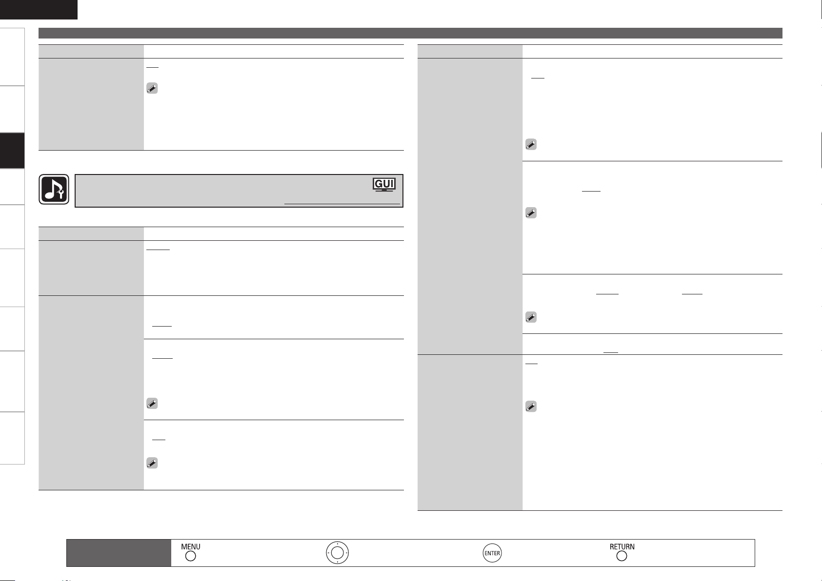
ENGLISH
Getting Started Connections Playback Remote ControlMulti-zone Information Troubleshooting Specifications
Making Detailed Settings (Manual Setup)
Setting items Setting contents
Power Off Control
The power of the AVR-3310
and external device turn off
together.
Settings
Making the Audio Settings (Audio Setup)
Make settings for audio playback.
Setting items Setting contents
EXT. IN SW Level
Set the playback level of the
analog subwoofer signals input from the external input
terminals (EXT. IN).
2ch Direct/Stereo
Make speaker settings for 2channel mode playback.
ON : Switched.
OFF : Not switched.
This can be set when “HDMI Control” is set to “ON”.
•
Please consult the operating instructions for each connected device to
•
check the settings.
For details on the HDMI control function, see “HDMI Control Function”
•
(vpage 75).
Default settings are underlined.
+15dB : This is the recommended level.
+10dB / +5dB / 0dB : Select the level according to the player being
used.
Setting : Select the method for setting the speakers used in the 2-channel
direct and stereo playback modes.
Basic : The settings at “Speaker Setup” (vpage 33) are applied.
•
Custom : Make separate settings for 2-channel.
•
Front : Set the front speaker size.
Large : Use of a large speaker that can adequately playback low
•
frequencies.
Small : Use of a small speaker that has inadequate playback capacity for
•
low frequencies.
If “Speaker Configuration” – “Subwoofer” (vpage 33) is set to
“No”, the setting is automatically set to “Large”.
Subwoofer : Set the presence of a subwoofer.
Yes : Use a subwoofer.
•
No : Select when a subwoofer is not connected.
•
If “Speaker Configuration” – “Subwoofer” (vpage 33) is set to
“No”, the setting is automatically set to “No”. If the “Front” setting is
“Small”, the setting is automatically “Yes”.
Setting items Setting contents
2ch Direct/Stereo
(Continued)
Auto Surround Mode
Make setting for memorizing
surround mode setting for
each input signal type.
SW Mode : Select low range signal to be reproduced by subwoofer.
LFE : When the “2ch Direct/Stereo” – “Front” setting is set to “Large”,
•
the LFE signal alone is output from the subwoofer. Also, when the “2ch
Direct/Stereo” – “Front” setting is set to “Small”, the front channel low
range signal is added to the LFE signal output from the subwoofer.
LFE+Main : The front channel low range signal is added to the LFE signal
•
output from the subwoofer.
This can be set when “2ch Direct/Stereo” – “Subwoofer” is set to
“Yes”.
Crossover : Outputs at below set frequency, each speaker’s bass signal
output from the subwoofer.
40Hz / 60Hz / 80Hz / 90Hz / 100Hz / 110Hz / 120Hz / 150Hz / 200Hz /
•
250Hz
This can be set when “2ch Direct/Stereo” – “Subwoofer” is set to
•
“Yes”.
If the “2ch Direct/Stereo” – “Front” setting is “Large” and the “SW
•
Mode” setting is “LFE”, “Full Band” is displayed and the setting cannot
be made.
Distance FL / Distance FR : Select the speaker.
0.00m ~ 18.00m (3.60m) / 0.0ft ~ 60.0ft (12.0ft) : Set the distance to
•
the speaker.
Set so that the difference between the front left speaker and front
right speaker distances is 6.0 m (20.0 ft) or less.
Level FL / Level FR : Select the speaker.
–12.0dB ~ +12.0dB (0dB) : Adjust the level of each channel.•
ON : Memorize settings. Automatically play with the last used surround
mode.
OFF : Do not memorize settings. Surround mode does not change
according to input signal
The auto surround mode function lets you store in the memory the
•
surround mode last used for playing the four types of input signals listed
below.
q Analog and PCM 2-channel signals
w Dolby Digital and DTS 2-channel signals
e Dolby Digital and DTS multi-channel signals
r Multi-channel signals other than Dolby Digital and DTS (PCM etc.)
When playing in the PURE DIRECT, the surround mode does not change
•
even if the input signal is changed.
Main remote control
operation buttons
:Displaying the menu
Cancel the menu
:Moves the cursor
(Up/Down/Left/Right)
:Confirm the setting :Return to previous menu
Page 41
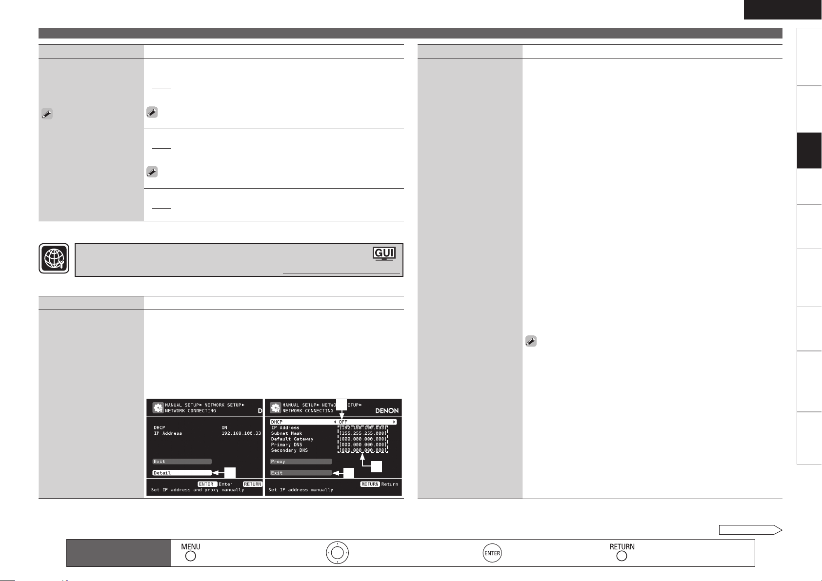
ENGLISH
Making Detailed Settings (Manual Setup)
Getting Started Connections Playback Remote ControlMulti-zone Information Troubleshooting Specifications
Setting items Setting contents
EQ Customize
Set so that unused equalizer
settings are not displayed
when MULTEQ is pressed.
Equalizer settings for which
“Not Used” is set with the
Quick Select function cannot
be stored and called out.
Audyssey Byp. L/R : Set when not using the “Audyssey Byp L/R”
equalizer.
Used : Use.
•
Not Used : Do not use.
•
Set so that “Audyssey Byp. L/R” settings can be made when
Audyssey™ Auto Setup procedure is performed.
Audyssey Flat : Set when not using the “Audyssey Flat” equalizer.
Used : Use.
•
Not Used : Do not use.
•
Set so that “Audyssey Flat” settings can be made when Audyssey™
Auto Setup procedure is performed.
Manual : Set when not using the “Manual” equalizer.
Used : Use.
•
Not Used : Do not use.
•
Making the Network Settings (Network Setup)
Make network settings.
Setting items Setting contents
Network Connecting
Make settings for wired
LAN.
1. Connect the LAN cable (vpage 22 “Connecting to a Home Network
(LAN)”).
2. Turn on the AVR-3310 (vpage 23 “Turning the Power On”).
AVR-3310 performs automatic network setup due to the DHCP
function.
When connecting to a network that has no DHCP function, perform the
setting in step 3.
3. Set the IP address at the “Network Connecting”.
q
Default settings are underlined.
w
r
Setting items Setting contents
Network Connecting
(Continued)
e
q On the GUI menu, select “Network Connecting” – “Detail” and
press ENTER.
w Use o p to set “DHCP” to “OFF”, then press i.
The DHCP function is disabled.
e Use uip to input the address and press ENTER.
IP Address
•
The Network Audio function cannot be used if other IP addresses
are set.
CLASS A: 10.0.0.0 ~ 10.255.255.255
CLASS B: 172.16.0.0 ~ 172.31.255.255
CLASS C: 192.168.0.0 ~ 192.168.255.255
Subnet Mask : When connecting an xDSL modem or terminal
•
adapter directly to the AVR-3310, input the subnet mask indicated
in the documentation supplied by your provider. Normally input
255.255.255.0.
Default Gateway : When connected to a gateway (router), input
•
its IP address.
Primary DNS, Secondary DNS : If there is only one DNS address
•
indicated in the documentation supplied by your provider, input it
at “Primary DNS”. If there are two or more DNS addresses, input
the first one at “Secondary DNS”.
r Use i to select “Exit” and press ENTER.
Setup is complete.
When connecting to the network via a Proxy server, select “Proxy” and
b
press ENTER (vpage 38 “Proxy settings”).
If you are using a broadband router (DHCP function), there is no need
•
to make the settings at “IP Address” and “Proxy”, since the DHCP
function is set to “ON” in the AVR-3310’s default settings.
If the AVR-3310 is being used connected to a network without the
•
DHCP function, the network settings must be made. In this case, some
knowledge of networks is required. For details, consult a network
administrator.
If you cannot connect to the Internet, recheck the connections and
•
settings (vpage 22).
If you do not understand about Internet connection, contact your ISP
•
(Internet Service Provider) or the store from which you purchased your
computer.
When you want to cancel the setting during IP address input, press
•
: Set the IP address within the ranges shown below.
Settings
RETURN.
Main remote control
operation buttons
:Displaying the menu
Cancel the menu
:Moves the cursor
(Up/Down/Left/Right)
:Confirm the setting :Return to previous menu
See overleaf
Page 42

ENGLISH
Getting Started Connections Playback Remote ControlMulti-zone Information Troubleshooting Specifications
Making Detailed Settings (Manual Setup)
Setting items Setting contents
Network Connecting
(Continued)
Settings
Proxy settings : Make this setting when connecting to the Internet via a
proxy server.
w
q
e
r
y
u
q On the GUI menu, select “Network Connecting” – “Detail” and press
t
ENTER.
w Use ui to set “Proxy” and press ENTER.
e Use o p to set “Proxy” to “ON” and press i.
The proxy server is enabled.
r Use o p to select the proxy server input method, and then press i.
Address : Select when inputting by address.
Name : Select when inputting by domain name.
t Use uio p to input the proxy server address or domain name and
press ENTER.
When “Address” is selected in step r : Input the address
When“Name” is selected in step r : Input the domain name
The types of characters that can be input are as shown below.
GLower case charactersH abcdefghijklmnopqrstuvwxyz
GUpper case charactersH ABCDEFGHIJKLMNOPQRSTUVWXYZ
GSymbolsH ! “ # $ % & ’ ( ) * + , - . / : ; < = > ? @ [ \ ] ˆ _ ` { | } ˜
(Space)
GNumbersH 0123456789
You can change the character type when you press [SEARCH]
during character input.
Setting items Setting contents
Network Connecting
(Continued)
Other
Network function on/off
setting during standby, and
PC language setting.
y Use uio p to input the proxy server port number and press
ENTER.
u Use i to select “Exit” and press ENTER.
Setup is complete.
Network Standby : Set the network function on/off during standby.
ON : Network is on during standby. Main unit operable with a network-
•
compatible controller.
OFF : Suspend network function during standby.
•
Set to “ON” when using the web control function.
PC Language : Select computer environment language.
ara / chi (smpl) / chi (trad) / cze / dan / dut / eng / fin / fre / ger / gre
•
/ heb / hun / ita / jpn / kor / nor / pol / por / por(BR) / rus / spa / swe
/ tur
Friendly Name Edit : The Friendly Name is the name AVR-3310 displayed
on the network. Up to 63 characters can be input. The default Friendly
Name on first use is “DENON:[AVR-3310]”.
The types of characters that can be input are as shown below.
GLower case charactersH abcdefghijklmnopqrstuvwxyz
GUpper case charactersH ABCDEFGHIJKLMNOPQRSTUVWXYZ
GSymbolsH ! “ # $ % & ’ ( ) * + , - . / : ; < = > ? @ [ \ ] ˆ _ ` { | } ˜
(Space)
GNumbersH 0123456789
You can change the character type when you press [SEARCH] during
character input.
Default : Reset all settings to factory default.
Yes : Reset to the defaults.
•
No : Do not reset to the defaults.
•
When you select “Default” and press ENTER, the “Default Setting?”
prompt is displayed. Select either “Yes” or “No”, and press ENTER.
Party Mode Function : Set the Party Mode function.
OFF : Disable Party Mode function.
•
ON : Enable Party Mode function.
•
Refer to page 77, “Playing the Same Network Audio on Different
Devices Connected in a Network (Party Mode Function)” for more
information on the party mode function.
Main remote control
operation buttons
:Displaying the menu
Cancel the menu
:Moves the cursor
(Up/Down/Left/Right)
:Confirm the setting :Return to previous menu
Page 43

ENGLISH
Making Detailed Settings (Manual Setup)
Getting Started Connections Playback Remote ControlMulti-zone Information Troubleshooting Specifications
Setting items Setting contents
Other
(Continued)
Party Start Level : Make settings for volume level when the Party Mode
is started.
Last : The same volume as set before the party mode was started.
•
– – – (0) : Always use the muting on condition when the Party Mode is
•
started.
–80dB ~ 18dB (1 ~ 99) : Start party mode with your preferred volume.
•
This can be set when “Party Mode Function“ is set to “ON“.
•
This is displayed from 0 to 99 when “Volume Display” (vpage 40) is
•
set to “Absolute”.
You can set to the upper limit set with “Volume Limit” (vpage 40) .
•
Network Status : Displays up to a maximum of 10 DENON products
connected on the same network.
Friendly Name / Model Name / Power ON/Standby / Select Source /
•
Volume Level / Party Mode status
“Network Status” is only displayed for DENON products supporting
the Network Status function.
Update Notification : Displays a notification message on the AVR-3310’s
GUI screen when the latest firmware is released with “Firmware Update”.
The notification message is displayed for about 20 seconds when the
power is turned on. Connect to broadband Internet (vpage 22) when
using this function.
ON : Display update message.
•
OFF : Do not display upgrade message.
•
When you press ENTER during display of the notification message, the
•
“Check for Update” screen is displayed. (Refer to page 42 for more
information on “Firmware Update”)
Press RETURN to erase the notification message.
•
Upgrade Notification : Display a notification message on the AVR-3310’s
GUI screen when downloadable firmware is released with “Add New
Feature”. The notification message is displayed for about 20 seconds
when the power is turned on. Connect to broadband Internet (vpage
22) when using this function.
ON : Display update message.
•
OFF : Do not display upgrade message.
•
When you press ENTER during display of the notification message, the
•
“Add New Feature” screen is displayed. (Refer to page 43 for more
information on “Add New Feature”)
Press RETURN to erase the notification message.
•
Setting items Setting contents
Napster Account
Set or change Username
and Password (vpage 60
“Listening to Napster“).
Network Information
Display network information.
Username / Password
The types of characters that can be input are as shown below.
GLower case charactersH abcdefghijklmnopqrstuvwxyz
GUpper case charactersH ABCDEFGHIJKLMNOPQRSTUVWXYZ
GSymbolsH ! “ # $ % & ’ ( ) * + , - . / : ; < = > ? @ [ \ ] ˆ _ ` { | } ˜
(Space)
GNumbersH 0123456789
You can change the character type when you press [SEARCH] during
•
character input.
The password may not contain underscores ( _ ).
•
Friendly Name / DHCP= ON/OFF / IP Address / MAC Address
Making the Multi-zone Settings (Zone Setup)
Set the audio to playback with multi-zone (ZONE2, ZONE3).
Setting items Setting contents
Bass
Adjust low frequency range
(bass).
Treble
Adjust high frequency range
(treble).
HPF
Make settings for cutting
the low range to reduce
distortion in the bass.
Level Lch
Adjust the left channel
output level.
Level Rch
Adjust the right channel
output level.
–10dB ~ +10dB (0dB)
–10dB ~ +10dB (0dB)
OFF : The low range is not attenuated.
ON : The low range is attenuated.
–12dB ~ +12dB (0dB)
The “Level Lch” can be set when “Channel“ (vpage 40) is set to
“Stereo“.
–12dB ~ +12dB (0dB)
The “Level Rch” can be set when “Channel“ (vpage 40) is set to
“Stereo“.
Settings
Default settings are underlined.
See overleaf
Main remote control
operation buttons
:Displaying the menu
Cancel the menu
:Moves the cursor
(Up/Down/Left/Right)
:Confirm the setting :Return to previous menu
Page 44

ENGLISH
OPTION
Getting Started Connections Playback Remote ControlMulti-zone Information Troubleshooting Specifications
Making Detailed Settings (Manual Setup)
Setting items Setting contents
Channel
Set the signal output from
multi-zone.
Volume Display
Set how volume is
Settings
displayed.
Volume Level
Set the volume output level.
Volume Limit
Make a setting for maximum
volume.
Power On Level
Define the volume setting
that is active when the
power is turned on.
Mute Level
Set the amount of attenuation
when muting is on.
Stereo : Select stereo output.
Mono : Select mono output.
When “Amp Assign” (vpage 33) is set to “ZONE2/3-MONO”, the
“Channel” setting is automatically set to “Mono”.
Relative : Display - - - dB (Min), in the range –80 dB ~ 18 dB.
Absolute : Display in the range 0 (Min) ~ 99.
The “Volume Display” setting is applied also to the “Volume Level”,
•
“Volume Limit” and “Power On Level” display method.
The “Volume Display” setting applies to all zones.
•
Variable : Volume adjustment enabled by main unit and remote
controller.
–40dB (41) : Fix volume at –40 dB. Set when adjusting volume by external
amp.
0dB (81) : Fix volume at 0 dB. Set when adjusting volume by external
amp.
When “Amp Assign” (vpage 33) is set to “ZONE2”, “ZONE3” or
“ZONE2/3-MONO”, the “Volume Level” setting is automatically set
to “Variable”.
OFF : Do not set a maximum volume.
–20dB (61) / –10dB (71) / 0dB (81)
Can be set when the multi-zone “Volume Level” setting (vpage 40)
is “Variable”.
Last : Use the memorized setting from the last session.
– – – (0) : Always use the muting on condition when power is turned on.
–80dB ~ 18dB (1 ~ 99) : The volume is adjusted to the set level.
Can be set when the multi-zone “Volume Level” setting (vpage 40)
is “Variable”.
Full : The sound is muted entirely.
–40dB : The sound is attenuated by 40 dB down.
–20dB : The sound is attenuated by 20 dB down.
Making Other Settings (Option Setup)
Setting items Setting contents
Volume Control
Set the MAIN ZONE volume
setting.
Source Delete
Remove input sources
that are not used from the
display.
GUI
Make GUI related settings.
Volume Display : Set how volume is displayed.
Relative : Display - - - dB (Min), in the range –80 dB ~ 18 dB.
•
Absolute : Display in the range 0 (Min) ~ 99.
•
The “Volume Display” setting is applied also to the “Volume Limit” and
•
“Power On Level” display method.
The “Volume Display” setting applies to all zones.
•
Volume Limit : Make a setting for maximum volume
OFF : Do not set a maximum volume.
•
–20dB (61) / –10dB (71) / 0dB (81)
•
Power On Level : Define the volume setting that is active when the
power is turned on.
Last : Use the memorized setting from the last session.
•
– – – (0) : Always use the muting on condition when power is turned
•
on.
–80dB ~ 18dB (1 ~ 99) : The volume is adjusted to the set level.
•
Mute Level : Set the amount of attenuation when muting is on.
Full : The sound is muted entirely.
•
–40dB : The sound is attenuated by 40 dB down.
•
–20dB : The sound is attenuated by 20 dB down.
•
PHONO / CD / DVD / HDP / TV / SAT/CBL / VCR / DVR / V.AUX / NET/
USB / TUNER : Select input source that is not used.
ON : Use this source.
•
Delete : Do not use this source.
•
NOTE
Input sources being used in the various zones cannot be deleted.
•
Input sources set to “Delete” cannot be selected using SOURCE
•
SELECT.
Screensaver : Make screensaver settings.
ON : The screen saver is activated during GUI menu display or NET/USB
•
/ iPod / TUNER screen display if no operation is performed approximately
for a continuous 3-minute period. When you press uio p, the screen
saver is cancelled and the screen before that screen saver started is
displayed.
OFF : Screen saver is not activated.
•
Default settings are underlined.
0
Main remote control
operation buttons
:Displaying the menu
Cancel the menu
:Moves the cursor
(Up/Down/Left/Right)
:Confirm the setting :Return to previous menu
Page 45

ENGLISH
Making Detailed Settings (Manual Setup)
Getting Started Connections Playback Remote ControlMulti-zone Information Troubleshooting Specifications
Setting items Setting contents
GUI
(Continued)
Wall Paper : Set wallpaper to display the background when playback is
stopped, etc.
Picture : Set the background to a picture (DENON logo).
•
Black : Set the background to black.
•
Format : Set the video signal format to be output for the TV you are
using.
NTSC : Select NTSC output.
•
PAL : Select PAL output.
•
The “Format” can also be set by the following procedure. However,
the GUI screen is not displayed.
1. Press and hold the <AUDIO DELAY> and <RETURN> for at least 3
seconds.
“Video Format” appears on the display.
2. Press o p and set the video signal format.
3. Press the <ENTER>, <MENU> or <RETURN> to complete the
setting.
NOTE
When a format other than the video format of the connected TV is set, the
picture will not be displayed properly.
Text : Display the content of operation during switching of surround mode,
input mode, etc.
ON : Turn display on.
•
OFF : Turn display off.
•
Master Volume : Master volume display during adjustment.
Bottom : Display at the bottom.
•
Top : Display at the top.
•
OFF : Turn display off.
•
When the master volume display is hard to see when superimposed
on movie subtitles, set to “Top”.
NET/USB : Set the NET/USB screen display time when the input source
is “NET/USB”.
Always : Show display continuously.
•
30s : Show display for 30 seconds after operation.
•
10s : Show display for 10 seconds after operation.
•
OFF : Turn display off.
•
iPod : Set the iPod screen display time when the input source is “iPod”.
Always : Show display continuously.
•
30s : Show display for 30 seconds after operation.
•
10s : Show display for 10 seconds after operation.
•
OFF : Turn display off.
•
Setting items Setting contents
GUI
(Continued)
Quick Select Name
Change the “Quick Select”
display title to one you
prefer.
Zone Rename
Change the display title of
each zone to one you prefer.
Tuner : Set the tuner screen display time when the input source is
“TUNER”.
Always : Show display continuously.
•
30s : Show display for 30 seconds after operation.
•
10s : Show display for 10 seconds after operation.
•
OFF : Turn display off.
•
1. Use ui to select the name of the Quick Select setting you want to
change, then press p or ENTER.
2. Use o p to set the cursor to the character you want to change.
3. Use ui to change the character, then press ENTER.
Up to 16 characters can be input.
•
You can change the character type when you press [SEARCH] during
•
character input.
The types of characters that can be input are as shown below.
•
GUpper case charactersH ABCDEFGHIJKLMNOPQRSTUVWXYZ
GLower case charactersH abcdefghijklmnopqrstuvwxyz
GSymbolsH ! “ # $ % & ’ ( ) * + , - . / : ; < = > ? @ [ \ ] ˆ _ ` { | } ˜
(Space)
GNumbersH 0123456789
4. Repeat steps 1 ~ 3 to change the display name.
1. Use ui to select the zone name (MAIN ZONE, ZONE2 or ZONE3) you
want to change, then press p or ENTER.
2. Use o p to set the cursor to the character you want to change.
3. Use ui to change the character, then press ENTER.
Up to 10 characters can be input.
•
You can change the character type when you press [SEARCH] during
•
character input.
The types of characters that can be input are as shown below.
•
GUpper case charactersH ABCDEFGHIJKLMNOPQRSTUVWXYZ
GLower case charactersH abcdefghijklmnopqrstuvwxyz
GSymbolsH ! “ # $ % & ’ ( ) * + , - . / : ; < = > ? @ [ \ ] ˆ _ ` { | } ˜
(Space)
GNumbersH 0123456789
4. Repeat steps 1 ~ 3 to change the display name.
Settings
Main remote control
operation buttons
:Displaying the menu
Cancel the menu
:Moves the cursor
(Up/Down/Left/Right)
:Confirm the setting :Return to previous menu
See overleaf
Page 46

ENGLISH
Getting Started Connections Playback Remote ControlMulti-zone Information Troubleshooting Specifications
Making Detailed Settings (Manual Setup)
Setting items Setting contents
Trigger Out 1
Select the condition for
activating Trigger Out 1 for
the input source, surround
mode, etc.
See “TRIGGER OUT jacks”
(vpage 21) for more
Settings
information on trigger out.
Trigger Out 2
As with “Trigger Out 1”,
select the condition for
activating Trigger Out 2.
Remote ID
Set when you operate
another DENON AV amplifier
with the remote control unit
of the AVR-3310. Match the
remote control unit you are
using with the remote ID of
the AVR-3310.
232C Port
Set when using an external
controller or two-way remote
control connected to the RS232C terminal.
Dimmer
Adjust display brightness of
the receiver.
When Setting for Zone (MAIN ZONE / ZONE2 / ZONE3)
n
Trigger out is activated through linkage to the power of the zone set to
“ON”.
When Setting for Input Source
n
Activate trigger out when the input source set to “ON” is selected.
Valid for the zone set to “ON” with “When Setting for Zone”.
When Setting for Surround Mode
n
Activate trigger out when the surround mode set to “ON” is selected.
Valid when the “MAIN ZONE” set to “ON” with “When Setting
for Zone” is selected, and when the input source set to “ON” with
“When Setting for Input Source” is selected.
ON : Activate trigger on this mode.
•
– – – : Do not activate trigger on this mode.
•
1 / 2 / 3 / 4
When using the AVR-3310 with only the included main remote control
unit (RC-1118), use Remote ID “1” (default).
When using the included sub remote control unit (RC-1121) and a
separately sold remote control unit (RC-7000CI, etc.), this function
can be used. Match the ID setting of the remote control unit and the
receiver.
Serial Control : Set when using an external controller.
2Way Remote : Set when using a 2-way remote control unit.
When using a DENON two-way remote control (RC-7000CI or RC-
7001RCI, sold separately), set to “2Way Remote”.
NOTE
When setting to “2Way Remote”, you can not use the RS-232C connector
as an external controller.
Bright : Normal display brightness.
Dim : Reduced display brightness.
Dark : Very low display brightness.
OFF : Turns the display off.
Setting items Setting contents
Setup Lock
Protect settings from
inadvertent change.
Maintenance Mode
Used when receiving
maintenance from a DENON
service engineer or custom
installer.
Firmware Update
Update the firmware of the
receiver.
OFF : Turn protection off.
ON : Turn protection on.
When “Setup Lock” is set to “ON”, the settings listed below can no
•
longer be changed. Also, “SETUP LOCKED!” is displayed if you attempt
to operate related settings.
· GUI menu operations · Dynamic Volume
· RESTORER · Channel Level
· Audio/Video Adjust · Audio Delay
· MultEQ · Input Mode
· Dynamic EQ
When canceling the setting, set “Setup Lock” to “OFF”.
•
NOTE
Only use this function if so instructed by a DENON serviceperson or
installer.
Check for Update : You can check for firmware updates. You can also
check approximately how long it will take to complete an update.
Start : Execute the update process.
When updating starts, the power indicator becomes red and the GUI
screen is shut down. The amount of update time which has elapsed is
displayed.
When updating is complete the power indicator becomes green and
normal status is resumed.
If updating fails, the set automatically retries, but if updating is still not
b
possible, one of the messages shown below is displayed. If the display
reads as shown below, check the settings and network environment,
then update again.
Display Description
Updating failed Updating failed.
Login failed Failure to log into server.
Server is busy Server is busy. Wait a while then try again.
Connection fail Failure connecting to server.
Download fail Downloading of the firmware has failed.
Main remote control
operation buttons
:Displaying the menu
Cancel the menu
:Moves the cursor
(Up/Down/Left/Right)
:Confirm the setting :Return to previous menu
Page 47

Making Detailed Settings (Manual Setup)
Setting items Setting contents
Add New Feature
Display the new functions
(payment required) which
can be purchased for
downloading to the AVR3310 and upgrade.
When you purchase a
new function and register
your user information,
“Registered” is displayed
on this menu and you can
proceed with the upgrade.
Upgrade : Execute the upgrade process.
When updating starts, the power indicator becomes red and the GUI
screen is shut down. The amount of update time which has elapsed is
displayed.
When updating is complete the power indicator becomes green and
normal status is resumed.
If the upgrade is not successful, an error message identical to those in
b
“Firmware Update” will appear on the display, check the settings and
network environment, then update again.
Upgrade Status : A list of the additional functions provided by the Upgrade
will be displayed.
When “Not Registered” is displayed on the Add New Feature screen,
you cannot upgrade.
To use the upgrade function, you should purchase an upgrade package
from the DENON website.
To purchase the package, you will need the ID number shown on this
screen.
To display the ID number on the screen, hold <p> and <STATUS>
down for 3 seconds or more.
Notes concerning use of “Firmware Update” and “Add New Feature”
In order to use these functions, you must have the correct system requirements and settings for a
•
broadband Internet connection.
Do not turn off the power until updating or upgrating is completed.
•
Even with a broadband connection to the Internet, approximately 1 hour is required for the updating/
•
upgrading procedure to be completed.
Once updating/upgrading starts, normal operations on the AVR-3310 cannot be performed until
updating/upgrading is completed.
Furthermore, updating/upgrading the firmware may reset the backup data for the parameters, etc., set
for the AVR-3310.
The following backup data may be erased after an update or upgrade.
•
•
Internet radio preset channel
•
Internet radio Recently Played data
•
Care of data in Internet radio, media server and USB memory device
In the event of an update error during update or upgrade, turn the AVR-3310’s power off and then on
•
again. “Update Retry” appears on the display and update restarts from the point at which update failed.
If the error continues despite this, check the network environment.
Making the Input Settings
(Input Setup)
For details on how to select, set and cancel settings for each menu, see “GUI Menu
Operation” (vpage 25).
Make the settings related to the currently selected input source.
Before displaying the menu screen, press [SOURCE SELECT] to switch to the input source to be set.
The items that can be set differ according to the selected input source.
The set can be used without changing these settings. Make these settings as necessary.
For a description of “GUI Menu Map” and operating instructions, see page 24.
Items that can be set with the Input Setup proceduren
Changing the Input Terminal Assignments (Input Assign) vpage 44
Making the Video Settings (Video) vpage 46
Changing the Input Mode and Decoding Mode (Input Mode) vpage 47
Changing the Input Source’s Display Name (Rename) vpage 48
Correcting the Input Source’s Playback Level (Source Level) vpage 48
Setting the Playback Mode (Playback Mode) vpage 48
iPod (vpage 48)
n
NET/USB, Media Server, USB and Napster (vpage 49)
n
Making the Settings to Play Still Pictures (Still Picture) vpage 49
Automatically Presetting Radio Stations (Auto Preset) vpage 49
Setting Preset Channels so that They are not Displayed When Tuning
(Preset Skip) vpage 49
Giving Names to Preset Stations (Preset Name) vpage 49
ENGLISH
Getting Started Connections Playback Remote ControlMulti-zone Information Troubleshooting Specifications
Settings
Information regarding the “Firmware Update” function and “Add New Feature” will be announced on
•
the DENON web site each time related plans are defined.
When usable new firmware is released with “Firmware Update” or “Add New Feature”, a notification
•
message is displayed on the GUI screen. When you do not want to be notified, set “Update Notification”
(vpage 39) and “Upgrade Notification” (vpage 39) to “OFF”.
Main remote control
operation buttons
:Displaying the menu
Cancel the menu
:Moves the cursor
(Up/Down/Left/Right)
:Confirm the setting :Return to previous menu
Page 48
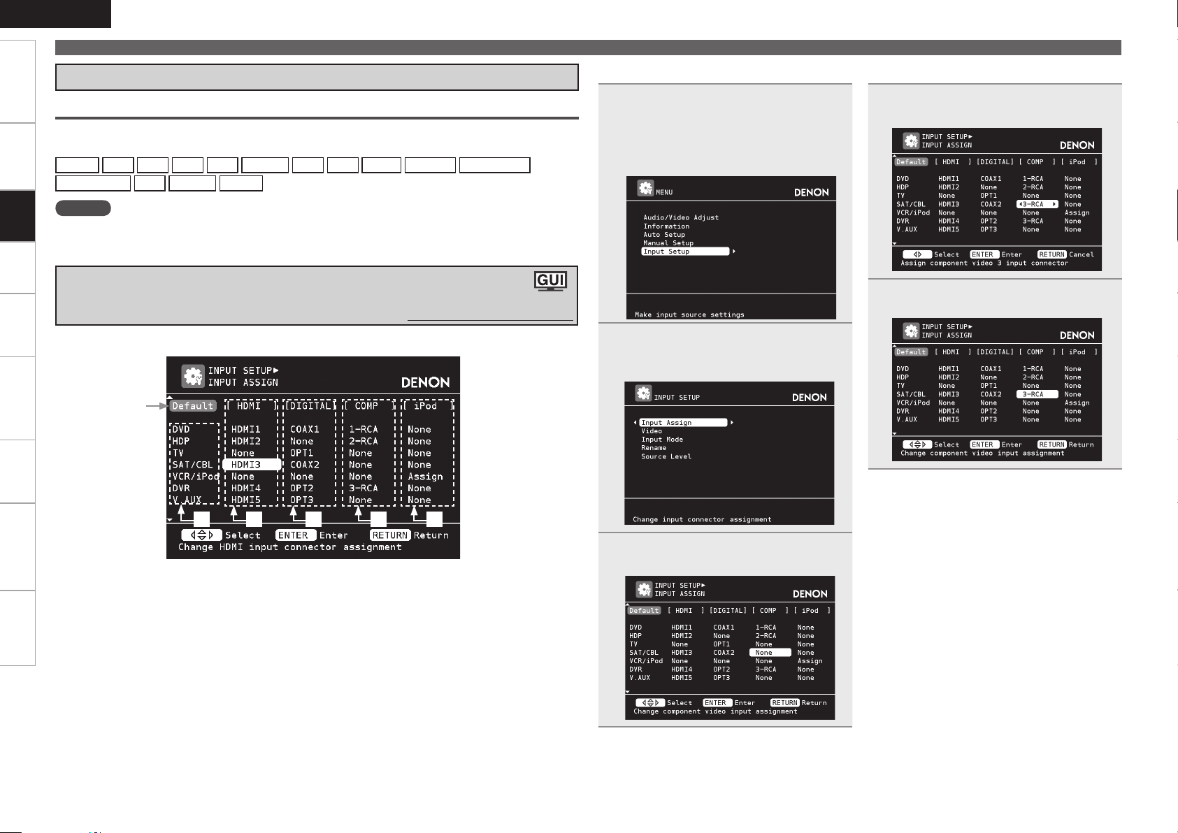
ENGLISH
Getting Started Connections Playback Remote ControlMulti-zone Information Troubleshooting Specifications
Making the Input Settings (Input Setup)
Important Information
About the Display of Input Sources in This Manual
In this manual, the names of input sources that can be set at the different items are indicated as shown
below.
PHONO CD DVD HDP TV SAT/CBL VCR DVR V.AUX NET/USB Internet Radio
Settings
Media Server USB Napster TUNER
NOTE
Input sources that have been set to “Delete” at “Source Delete” (vpage 40) cannot be selected.
Input Assignments Menu Operationsn
Press MENU.
1
The GUI menu is displayed on the TV
screen.
Use the ui to select “Input Setup”,
the press ENTER or p.
Press ENTER, then use o p to select
4
the input terminal to be assigned.
Changing the Input Terminal Assignments
(Input Assign)
Examples of Input Assign Menu Screen Displaysn
q
e
q Default button
w Input Source
e HDMI input
r t yw
r Digital audio input
t Component video input
y iPod dock
Default settings are underlined.
Select “Input Assign”, then press
2
ENTER or p.
The “INPUT ASSIGN” screen is displayed.
Use uio p to move the orange
3
highlight to the item you want to set.
Press ENTER to enter the setting.
5
Page 49
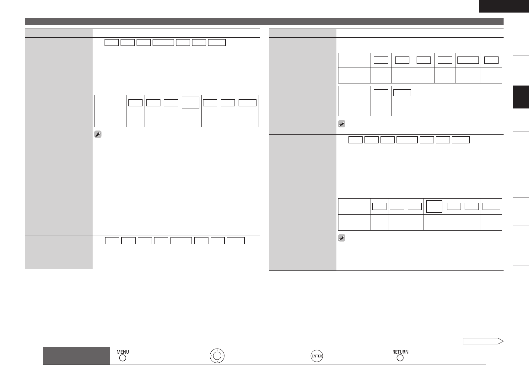
ENGLISH
Making the Input Settings (Input Setup)
Getting Started Connections Playback Remote ControlMulti-zone Information Troubleshooting Specifications
Setting items Setting contents
HDMI
Set this to change the HDMI
input terminals assigned to
the input sources.
Digital
Set this to change the digital
input terminals assigned to
the input sources.
DVD HDP TV SAT/CBL VCR DVR V.AUX
The
are assigned to the HDMI input terminals as shown below.
HDMI 1 / HDMI 2 / HDMI 3 / HDMI 4 / HDMI 5
None : Do not assign an HDMI input terminal to the selected input
source.
Upon purchase, the settings of the different input sources are as shown
b
below.
Input
source
Default
setting
An input source to which an HDMI input terminal cannot be assigned is
•
displayed as “– – –”.
To play the video signal assigned at “HDMI” combined with the audio
•
signal assigned at “Input Assign“ – “Digital”, select “Digital” at “Input
Mode” (vpage 47).
When the AVR-3310 and monitor are connected with an HDMI cable, if
•
the monitor is not compatible with HDMI audio signal playback, only the
video signals are output to the monitor.
The audio signals input from the analog, digital and EXT. IN connectors
•
are not output to the monitor.
When control dock for iPod is used as the input source, assignment of
•
the HDMI input terminal is disabled, even if it is assigned.
When “HDMI Control” (vpage 35) is set to “ON”, HDMI input terminal
•
cannot be assigned to “TV”.
CD DVD HDP TV SAT/CBL VCR DVR V.AUX
The
sources are assigned to the digital input terminals as shown below.
Coax 1 (Coaxial) / Coax 2 / Coax 3 / Opt 1 (Optical) / Opt 2 / Opt 3
None : Do not assign a digital input terminal to the selected input source.
DVD HDP TV
HDMI 1HDMI
2
None
SAT/
CBL
HDMI
3
input sources
VCR DVR V.AUX
HDMI 4HDMI
None
input
Setting items Setting contents
Digital
(Continued)
5
Component
Set this to change the
component video input
terminals assigned to the
input sources.
Upon purchase, the settings of the different input sources are as shown
b
below.
Input
source
Default
setting
Input
source
Default
setting
When control dock for iPod is used as the input source, assignment of
the digital input terminal is disabled, even if it is assigned.
The
DVD HDP TV SAT/CBL VCR DVR V.AUX
are assigned to the component video input terminals as shown below.
1-RCA (Component video 1) / 2-RCA (Component video 2) / 3-RCA
(Component video 3)
None : Do not assign a component video input terminal to the selected
input source.
Upon purchase, the settings of the different input sources are as shown
b
below.
Input
source
Default
setting
An input source to which a component video input terminal cannot be
•
assigned is displayed as “– – –”.
When control dock for iPod is used as the input source, assignment of
•
the component video input terminal is disabled, even if it is assigned.
CD DVD HDP TV SAT/CBL VCR
Coax 3 Coax 1 None Opt 1 Coax 2 None
DVR V.AUX
Opt 2 Opt 3
input sources
DVD HDP TV
1-RCA 2-RCA None None None 3-RCA None
SAT/
CBL
VCR DVR V.AUX
Settings
Main remote control
operation buttons
:Displaying the menu
Cancel the menu
:Moves the cursor
(Up/Down/Left/Right)
:Confirm the setting :Return to previous menu
See overleaf
Page 50
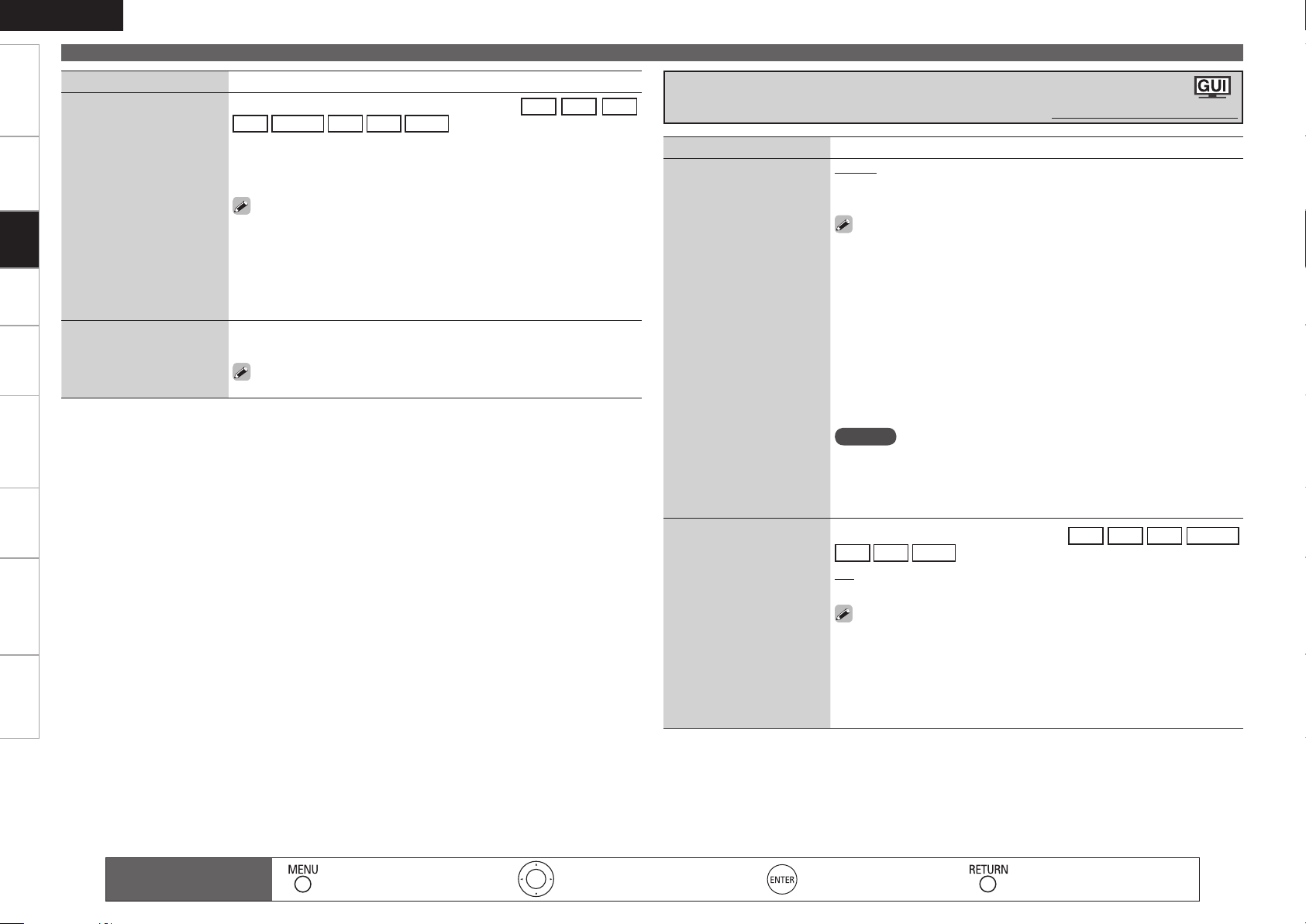
ENGLISH
Getting Started Connections Playback Remote ControlMulti-zone Information Troubleshooting Specifications
Making the Input Settings (Input Setup)
Setting items Setting contents
iPod dock
Assign the control dock for
iPod input.
Settings
Default
Reset all settings to factory
default.
The control dock for iPod can be assigned to the
TV SAT/CBL VCR DVR V.AUX
Assign : Assign the control dock for iPod to the selected input source.
None : Do not assign the control dock for iPod to the selected input
source.
By default on first use, it is assigned to “VCR (iPod)”.
•
An input source to which control dock for iPod cannot be assigned is
•
displayed as “– – –”.
If control dock for iPod is not connected to the AVR-3310, assignment
•
of the “iPod dock” is disabled, and you can use it as a standard input
source.
Yes : Reset to the defaults.
No : Do not reset to the defaults.
If you select “Default” and press ENTER the message “Default
Setting?” is displayed. Select “Yes” or “No”, and then press ENTER.
input sources.
CD DVD HDP
Making the Video Settings (Video)
Setting items Setting contents
Video Select
Change video input to your
preferred input source.
Video Convert
The input video signal is
converted automatically in
function of the connected
TV (vpage 10 “Converting
Input Video Signals for
Output (Video Conversion
Function)”).
Source : Play the picture and sound of the input source.
DVD / HDP / TV / SAT/CBL / VCR / DVR / V.AUX : Select video input
source to view. This can be set for individual input sources.
Set by either pressing <VIDEO SELECT> on the main unit or [VIDEO
SELECT] on the main remote control.
When operating from the main remote control unit
•
Press [VIDEO SELECT] repeatedly until the picture you want to see is
displayed.
To cancel, press [VIDEO SELECT], and select “Source”
When operating from the main unit
•
After pressing <VIDEO SELECT> on the main unit, turn the <SOURCE
SELECT> on the main unit until the picture you want to see is displayed.
To cancel, press <VIDEO SELECT>, then turn <SOURCE SELECT> and
select “Source”.
NOTE
It is not possible to select HDMI input signals.
•
The video select function does not work with HDMI signals.
•
Input sources for which “Delete” is selected at “Source Delete”
•
(vpage 40) cannot be selected.
This can be set when the input source is
VCR DVR V.AUX
ON : The input video signal is converted.
OFF : The input video signal is not converted.
When a non-standard video signal from a game machine or some other
•
source is input, the video conversion function might not operate. In this
case set “Video Convert” to “OFF”.
When “Video Convert” is set to “OFF”, the video conversion function
•
does not work. In this case, connect the AVR-3310 and TV with the same
type of cable.
Default settings are underlined.
DVD HDP TV SAT/CBL
.
Main remote control
operation buttons
:Displaying the menu
Cancel the menu
:Moves the cursor
(Up/Down/Left/Right)
:Confirm the setting :Return to previous menu
Page 51
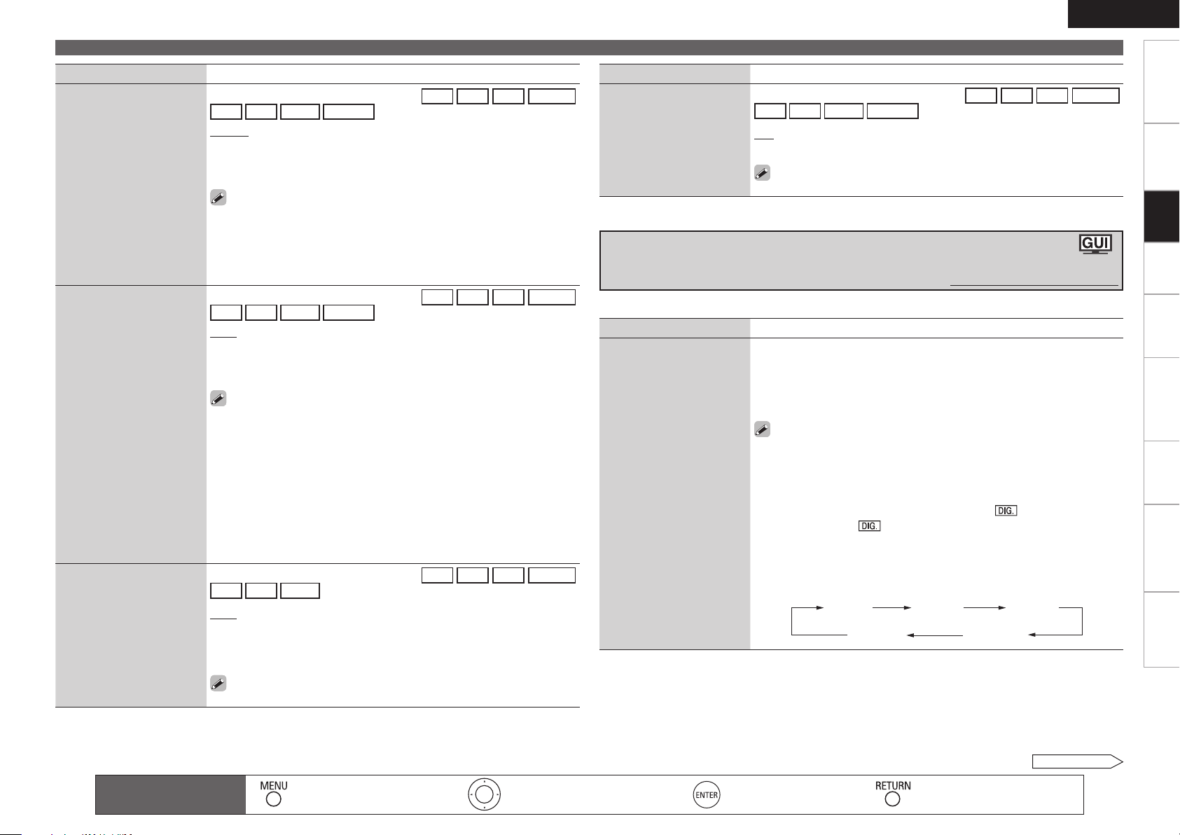
ENGLISH
Auto HDMI Digital
AnalogEXT. IN
Making the Input Settings (Input Setup)
Getting Started Connections Playback Remote ControlMulti-zone Information Troubleshooting Specifications
Setting items Setting contents
i/p Scaler
The input source’s resolution
is converted to the resolution
set at “Resolution”.
Resolution
Set resolution of the video
signal output to HDMI.
Progressive Mode
Select optimum progressive
mode for video material.
This can be set when the input source is
VCR DVR V.AUX NET/USB
Analog : Use i/p scaler function for analog video signal.
Analog & HDMI : Use i/p scaler function for analog and HDMI video
signal.
OFF : Do not use i/p scaler function.
This can be set when “Video Convert” is set to “ON”.
•
“Analog & HDMI” can be set for input sources for which an HDMI input
•
terminal is assigned.
When “i/p Scaler” is set to “Analog & HDMI”, it has no effect on the x.v.
•
Color signal or computer resolutions.
This can be set when the input source is
VCR DVR V.AUX NET/USB
Auto : The number of pixels the TV connected to the HDMI output terminal
supports is detected automatically and the appropriate output resolution
is set.
480p/576p / 1080i / 720p / 1080p / 1080p:24Hz : Set the output resolution.
This can be set when “i/p Scaler” is set to anything other than “OFF”.
•
When “i/p Scaler” is set to ”Analog & HDMI”, the resolution of both the
•
analog video input signal and HDMI input signal can be set.
To watch 1080p/24Hz pictures, use a TV that supports 1080p/24Hz video
•
signals.
When set to “1080p/24Hz”, you can enjoy film-like pictures for film
•
sources (in 24 Hz). For video sources and mixed sources, we recommend
setting the resolution to “1080p”.
It is not possible to convert a 50 Hz signal into 1080p/24Hz. It is output
•
at a resolution of 1080p/50Hz.
This can be set when the input source is
VCR DVR V.AUX
Auto : The video material is automatically detected and the appropriate
mode is set.
Video 1 : Select mode suitable for video playback
Video 2 : Select mode suitable for video and 30-frame film material playback.
This can be set when “i/p Scaler” is set to anything other than
“OFF”.
.
Setting items Setting contents
DVD HDP TV SAT/CBL
.
Aspect
Set the aspect ratio for the
video signals output to the
HDMI.
This can be set when the input source is
VCR DVR V.AUX NET/USB
Full : Output at 16:9 aspect ratio.
Normal : Output at 4:3 aspect ratio.
This can be set when “i/p Scaler” is set to anything other than
“OFF”.
.
DVD HDP TV SAT/CBL
Settings
Changing the Input Mode and Decoding Mode
(Input Mode)
Default settings are underlined.
DVD HDP TV SAT/CBL
.
DVD HDP TV SAT/CBL
The selectable input modes depend on the input source and “Input Assign” (vpage 44) setting.
Setting items Setting contents
Input Mode
Set the audio input modes for
the different input sources.
Auto : Automatically detect input signal and perform playback.
HDMI : Play only signals from HDMI input.
Digital : Play only signals from digital input.
Analog : Play only signals from analog input.
EXT. IN : Play only signals from EXT. IN input.
“HDMI” can be set for input sources for which “HDMI” is assigned at
•
“Input Assign”.
“Digital” can be set for input sources for which “Digital” is assigned at
•
“Input Assign”.
When digital signals are properly input, the ” ” indicator lights on
•
the display. If the ” ” indicator does not light, check the digital input
connector assignment and the connections.
The surround mode cannot be set if the input mode is set to “EXT. IN”.
•
This can also be set by pressing [INPUT MODE]. Each time you press the
•
button, the input mode display will change.
Main remote control
operation buttons
:Displaying the menu
Cancel the menu
:Moves the cursor
(Up/Down/Left/Right)
:Confirm the setting :Return to previous menu
See overleaf
Page 52
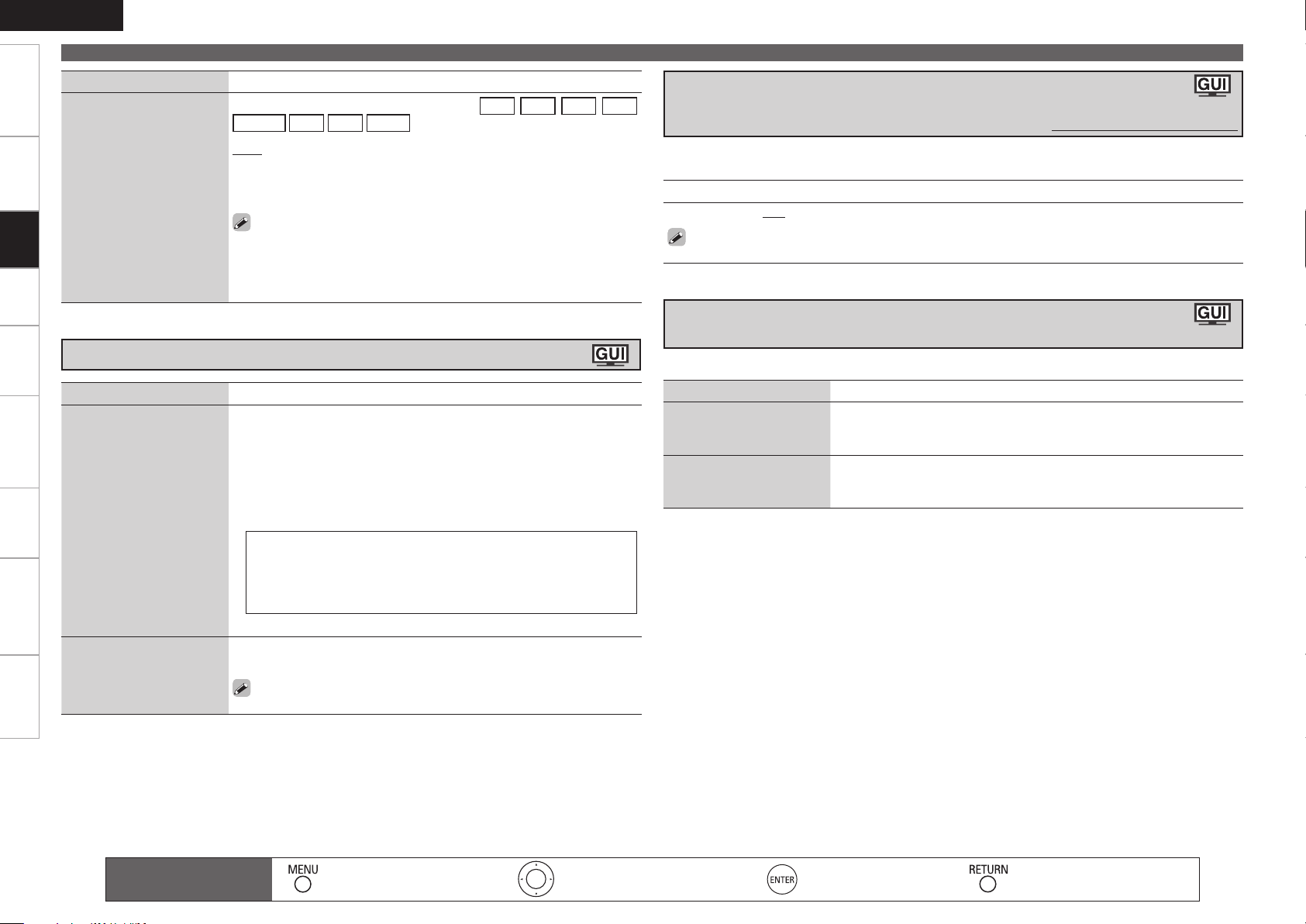
ENGLISH
Getting Started Connections Playback Remote ControlMulti-zone Information Troubleshooting Specifications
Making the Input Settings (Input Setup)
Setting items Setting contents
Decode Mode
Set the decode mode for
input source.
Settings
Changing the Input Source’s Display Name (Rename)
Setting items Setting contents
Rename
Change the display name of
the selected input source.
Default
Reset all settings to factory
default.
This can be set when the input source is
SAT/CBL VCR DVR V.AUX
Auto : Detect type of digital input signal and decode and play
automatically.
PCM : Decode and play only PCM input signals.
DTS : Decode and play only DTS input signals.
This can be set for input sources for which “HDMI” or “Digital” is
•
assigned at “Input Assign” (vpage 45).
Normally set this to “Auto”. Set “PCM” and “DTS” when inputting the
•
corresponding input signal.
1. Press p or ENTER.
2. Use o p to set the cursor to the character you want to change.
3. Use ui to change the character, then press ENTER.
Up to 8 characters can be input.
•
The input character type can be switched by pressing [SEARCH] while
•
the display name is being changed.
The types of characters that can be input are as shown below.
•
GUpper case charactersH ABCDEFGHIJKLMNOPQRSTUVWXYZ
GLower case charactersH abcdefghijklmnopqrstuvwxyz
GSymbolsH ! “ # $ % & ’ ( ) * + , - . / : ; < = > ? @ [ \ ] ˆ _ ` { | } ˜
(Space)
GNumbersH 0123456789
4. Repeat steps 2 and 3 to change the display name.
Yes : Reset to the defaults.
No : Do not reset to the defaults.
If you select “Default” and press ENTER the message “Default
Setting?” is displayed. Select “Yes” or “No”, and then press ENTER.
.
CD DVD HDP TV
Correcting the Input Source’s Playback Level
(Source Level)
Corrects the playback level of the selected input source’s audio input.
•
Set this if there are differences in the input volume levels between the different sources.
•
Default settings are underlined.
Setting contents
–12dB ~ +12dB (0dB)
The analog input level and digital input level can be adjusted independently for input sources for
which “HDMI” or “Digital” is assigned at “Input Assign“ (vpage 45).
Setting the iPod with iPod Dock Playback Mode
(Playback Mode)
This can be set for the input source for which “iPod dock” is assigned at “Input Assign” (vpage 46).
Setting items Setting contents
Repeat
Make settings for repeat
mode.
Shuffle
Make settings for shuffle
mode.
All : Repeat all songs.
One : Repeat the current song.
OFF : Cancel repeat mode.
Songs : Shuffle all songs.
Albums : Shuffle songs from current album only.
OFF : Cancel shuffle mode.
Main remote control
operation buttons
:Displaying the menu
Cancel the menu
:Moves the cursor
(Up/Down/Left/Right)
:Confirm the setting :Return to previous menu
Page 53
ENGLISH
Making the Input Settings (Input Setup)
Getting Started Connections Playback Remote ControlMulti-zone Information Troubleshooting Specifications
Setting the NET/USB, Media Server, USB and Napster
Playback Mode (Playback Mode)
Default settings are underlined.
This can be set when the input source is
NET/USB Media Server USB Napster
Setting items Setting contents
Direct Play
Use DIRECT PLAY on the
sub remote control unit to
set the folder to be played.
Repeat
Make settings for repeat
mode.
Random
Make random mode
settings.
Favorites : Play songs registered as “Favorites”.
Music : Play the songs saved on the PC media.
All : Repeat all files.
One : Repeat the current file.
OFF : Cancel repeat mode.
ON : Enable random playback.
OFF : Disable random playback.
Making the Settings to Play Still Pictures
(Still Picture)
Default settings are underlined.
This can be set when the input source is
NET/USB
.
Setting items Setting contents
Slide Show
Make slide show settings.
Interval
Set the playback time per
image.
ON : Display still picture images in a slide show.
OFF : Display only the selected still picture image.
5s ~ 60s (5s)
Automatically Presetting Radio Stations
(Auto Preset)
Setting Preset Channels so that They are not Displayed
When Tuning (Preset Skip)
Default settings are underlined.
.
Setting items Setting contents
A1 ~ G8
Set the preset channels that
you do not want to display.
This can be set when the input source is
ON : Display the selected preset channel.
Skip : Do not display the selected preset channel.
When set to “Block Presets” to “Skip”, it is possible to skip entire
preset memory blocks (A to G).
TUNER
.
Settings
Giving Names to Preset Stations (Preset Name)
Setting items Setting contents
A1 ~ G8
Select the preset channel.
Default
Reset all settings to factory
default.
This can be set when the input source is
1. Press p or ENTER.
2. Use o p to set the cursor to the character you want to change.
3. Use ui to change the character, then press ENTER.
Up to 8 characters can be input.
•
The input character type can be switched by pressing [SEARCH] while
•
the display name is being changed.
The types of characters that can be input are as shown below.
•
GUpper case charactersH ABCDEFGHIJKLMNOPQRSTUVWXYZ
GLower case charactersH abcdefghijklmnopqrstuvwxyz
GSymbolsH ! “ # $ % & ’ ( ) * + , - . / : ; < = > ? @ [ \ ] ˆ _ ` { | } ˜
(Space)
GNumbersH 0123456789
4. Repeat steps 2 and 3 to change the display name.
Yes : Reset to the defaults.
No : Do not reset to the defaults.
If you select “Default” and press ENTER the message “Default
Setting?” is displayed. Select “Yes” or “No”, and then press ENTER.
TUNER
.
Setting items Setting contents
Start
Start the auto preset
process.
Main remote control
operation buttons
This can be set when the input source is
If an FM station cannot be preset automatically, select the desired
station by tuning it in manually, then preset it manually.
:Displaying the menu
Cancel the menu
TUNER
.
:Moves the cursor
(Up/Down/Left/Right)
:Confirm the setting :Return to previous menu
Page 54
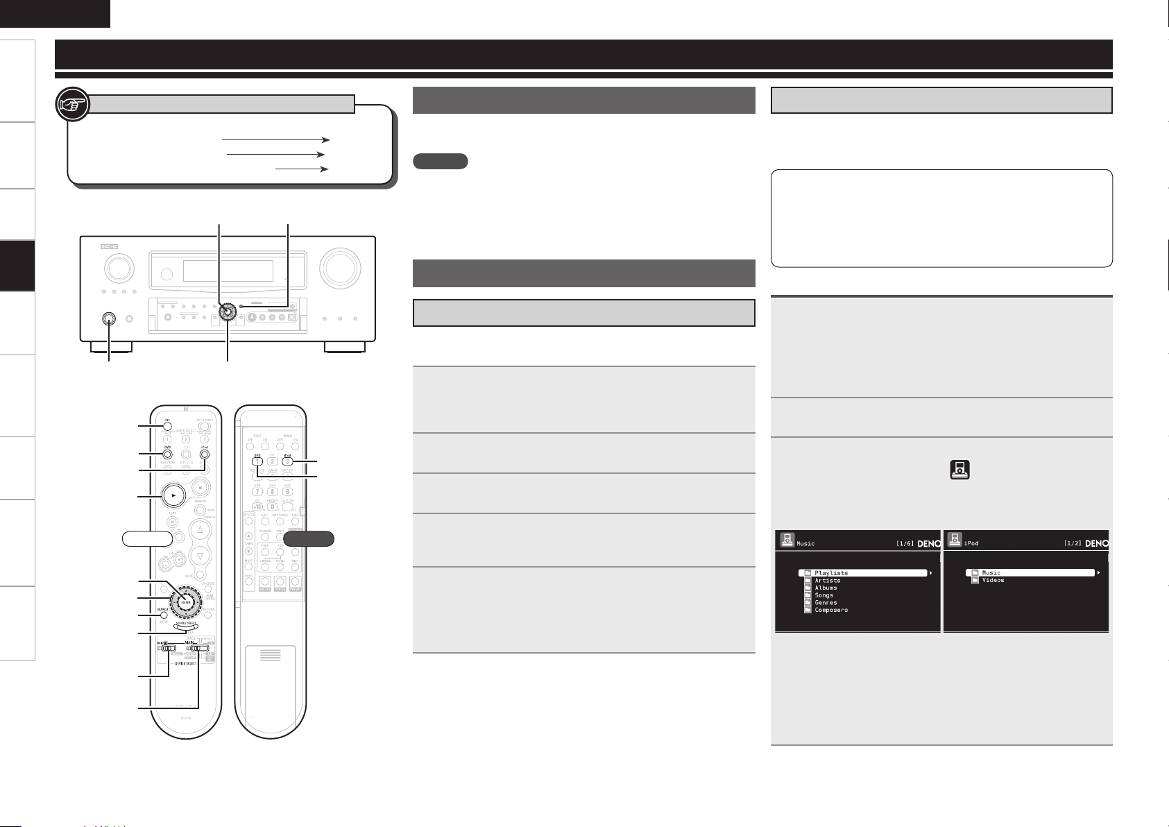
ENGLISH
uio p
<STATUS>
ENTER
<ON/STANDBY>
[SEARCH]
[OFF]
[1]
uio p
ENTER
[DVD]
[iPod]
[DEVICE
SELECT 1]
[DEVICE
SELECT 2]
[SOURCE
SELECT]
[DVD]
[iPod]
Getting Started Connections Settings Remote ControlMulti-zone Information Troubleshooting Specifications
Playback
Button located on both the main unit
and the remote control unit
Button only on the main unit
Button only on the remote control unit
Playback
0
Symbols used to indicate buttons in this manual
BUTTON
<BUTTON>
[BUTTON]
Front Rear
Important Information
Before starting playback, make the connections between the different
components and the settings on the receiver.
NOTE
Also refer to the operating instructions of the connected components
•
when playing them.
External devices can be controlled by remote control unit (vpage
•
83 “Operating the Connected Devices by Remote Control Unit”).
Playing Components
Playing a Blu-ray Disc Player/DVD Player
The following describes the procedure for playing Blu-ray disc player /
DVD player. Use the same procedure to play other components.
Playback preparation.
q Turn on the power of the TV, subwoofer and player.
1
w Switch the TV’s input to the AVR-3310.
e Load the disc in the player.
Turn the AVR-3310 power on.
(vpage 23 “Turning the Power On“)
2
Press [SOURCE SELECT] and select the input source.
3
Display the “SOURCE SELECT” menu (vpage 26).
Play the component connected to the AVR-3310.
Make the necessary settings on the player (language setting,
4
subtitles setting, etc.) beforehand.
Adjust the items below.
5
Adjusting the master volume (vpage 62)
n
Selecting the surround mode (vpage 64)
n
Adjusting the Sound and Picture Quality
n
(vpage 67)
iPod® Playback
When a DENON control dock for iPod (ASD-1R or ASD-11R, sold
separately) is used, you can play images and music stored on an
iPod®.
iPod is a trademark of Apple Inc., registered in the U.S. and other
countries.
The iPod may only be used to copy or play contents that are not
b
copyrighted or contents for which copying or playback is legally
permitted for your private use as an individual. Be sure to comply
with applicable copyright legislation.
Listening to music on an iPod
Playback preparation.
q Connecting the DENON control dock for iPod to the AVR-
1
3310 (vpage 16 “Control Dock for iPod”).
w Set the iPod® in the DENON control dock for iPod.
e Set [DEVICE SELECT 1] to “MAIN/TV” [DEVICE SELECT 2] to
“MAIN”.
Turn the AVR-3310 power on.
(vpage 23 “Turning the Power On”)
2
Press [SOURCE SELECT] to display the GUI Source
3
Select menu, then select “ ” (vpage 26).
The input source switches to the source to which the control
dock for iPod is assigned and the iPod menu is displayed.
– GUI screen –
(When using an ASD-1R) (When using an ASD-11R)
When using an ASD-11R, the “Music” and “Videos” folders are
b
displayed on the top menu.
Once communications between the AVR-3310 and the iPod are
b
completed, the connections screen is displayed on the iPod.
If the connections screen is not displayed, the iPod may not be
b
properly connected. Reconnect it.
®
Page 55

Press [SEARCH] and hold it down for a 2 seconds or
4
more to select the display mode.
There are two modes for display the contents recorded on the
b
iPod.
Browse mode
This is the mode for displaying the iPod information on the GUI
screen to operate the iPod. In this mode, you cannot perform
operations directly on the iPod itself.
z With the AVR-3310’s display, only English letters and numbers
�
and certain symbols can be displayed. Any characters that
cannot be displayed are replaced with “. (period)”.
Remote mode
This is the mode for performing operations directly on the iPod
itself while watching the screen displayed on the iPod. In this
mode, the GUI screen is not displayed.
z “Remote iPod” appears on the main unit’s display.
Display mode
Playable
files
Active
buttons
z1 : When using an ASD-11R DENON control dock for iPod.
z2 : Video may not be output, depending on the combination of
ASD-1R or ASD-11R DENON control dock for iPod and iPod.
:
:
Audio file
Picture file
Video file
Main remote
control unit
(AVR-3310)
®
iPod
Browse mode
S S
A
z1
S
S S
A S
Remote mode
S
S
z2
z2
To stop (vpage 62)
n
Stopping playback temporarily (vpage 62)
n
Fast-forwarding or fast-reversing (vpage 62)
n
To cue to the beginning of a track (vpage 62)
n
Playing repeatedly (vpage 63)
n
Shuffling playback (vpage 63)
n
Searching pages (vpage 63)
n
Use the RESTORER mode to expand the low and high frequency
•
components of compressed audio files and achieve a richer sound
(vpage 71). The default setting is “Mode 3”.
The title name, artist name and album name can be checked by
•
pressing <STATUS> during playback.
The time (default : 30 sec) for which the GUI menus are displayed
•
can be set at “GUI” – “iPod” (vpage 41). Press uio p to
return to the original screen.
Press [OFF] or <ON/STANDBY> and set the AVR-3310’s power to
•
the standby mode before disconnecting the iPod. Also switch the
input source to one to which the menu “iPod” is not assigned before
disconnecting the iPod.
NOTE
Depending on the type of iPod and the software version, some
•
functions may not operate.
DENON will accept no responsibility whatsoever for any loss of iPod
•
data.
ENGLISH
Playing Components
Viewing Videos on an iPod® in the Browse Mode
When an iPod equipped with a video function is connected to a
DENON ASD-11R control dock for iPod, video files can be played in
the browse mode.
Use ui to select “Videos”, then press ENTER or
1
p.
Use ui to select the search item or folder, then
2
press ENTER or p.
Use ui to select the video le, then press ENTER,
3
p or [1].
Playback starts.
Viewing Still Pictures and Videos on an iPod® in
the Remote Mode
Photos and videos on an iPod® equipped with a slide show or video
function can be played using DENON ASD-1R or ASD-11R control
dock for iPod.
Press and hold [SEARCH] to set the Remote mode.
“Remote iPod” is displayed on the AVR-3310’s display.
1
Watching the iPod’s screen, use ui to select
2
“Photos” or “Videos”.
Press ENTER until the image you want to view is
3
displayed.
Getting Started Connections Settings Remote ControlMulti-zone Information Troubleshooting Specifications
Playback
Use ui to select the item, then press ENTER or p
5
to select the le to be played.
Press [1], ENTER or p.
6
Playback starts.
Adjust the items below.
Adjusting the master volume (vpage 62)
n
7
Selecting the surround mode (vpage 64)
n
Adjusting the Sound and Picture Quality
n
(vpage 67)
“TV Out” at the iPod’s “Slide show Settings” or “Video Settings”
must be set to “On” in order to display the iPod’s photo data or videos
on the monitor. For details, see the iPod’s operating instructions.
NOTE
Video may not be output, depending on the combination of ASD-1R or
ASD-11R DENON control dock for iPod and iPod.
Page 56
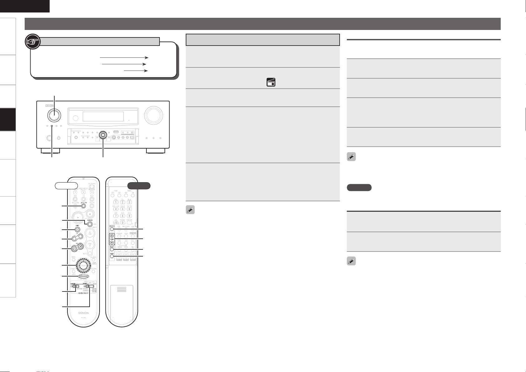
ENGLISH
ui<TUNING PRESET>
<SOURCE SELECT>
[DEVICE
SELECT 1]
[DEVICE
SELECT 2]
[SOURCE
SELECT]
[SHIFT]
[MEMORY]
[TUNER]
[TUNING]
[CHANNEL]
ui
[TUNING]
[MODE]
[TUNER]
[BAND]
Getting Started Connections Settings Remote ControlMulti-zone Information Troubleshooting Specifications
Tuning in Radio Stations
Playback
Symbols used to indicate buttons in this manual
Button located on both the main unit
and the remote control unit
Button only on the main unit
Button only on the remote control unit
Front Rear
BUTTON
<BUTTON>
[BUTTON]
Listening to FM/AM Broadcasts
Set [DEVICE SELECT 1] to “MAIN/TV” and [DEVICE
1
SELECT 2] to “MAIN”.
Press [SOURCE SELECT] to display the GUI Source
2
Select menu, then select “ ” (vpage 26).
Press [BAND] to select “FM” or “AM”.
3
Tune in the desired broadcast station.
4
q To tune in automatically (Auto Tuning)
Press [MODE] to light the “AUTO” indicator on the display, then
use [TUNING] to select the station you want to hear.
w To tune in manually (Manual Tuning)
Press [MODE] to turn off the display’s “AUTO” indicator, then
use [TUNING] to select the station you want to hear.
Adjust the items below.
Adjusting the master volume (vpage 62)
n
5
Selecting the surround mode (vpage 64)
n
Adjusting the Sound and Picture Quality
n
(vpage 67)
Presetting Radio Stations (Preset Memory)
Your favorite broadcast stations can be preset so that you can tune
them in easily. Up to 56 stations can be preset.
Tune in the broadcast station you want to preset.
1
Press [MEMORY].
2
Press [SHIFT] to select the block in which the channel
3
is to be preset, then press [CHANNEL] to select the
preset number.
Press [MEMORY] again to complete the setting.
4
To preset other stations, repeat steps 1 to 4.
•
Stations can be preset automatically at “Auto Preset” (vpage
•
49).
NOTE
Preset stations are erased by overwriting them.
Listening to Preset Stations
If the desired station cannot be tuned in with auto tuning, tune it in
•
manually.
When tuning in stations manually, press and hold [TUNING] to
•
change frequencies continuously.
The time (default : 30 sec) for which the GUI menu is displayed can
•
be set “GUI” – “Tuner” (vpage 41). Press uio p to return to
the original screen.
Press [SHIFT] to select the memory block (A to G).
1
Press [CHANNEL] to select the desired preset preset
2
channel.
You can also operate via the main unit. In this case, perform the
following operations.
Press <TUNING PRESET>, then turn <SOURCE SELECT> to select the
preset radio station.
Page 57
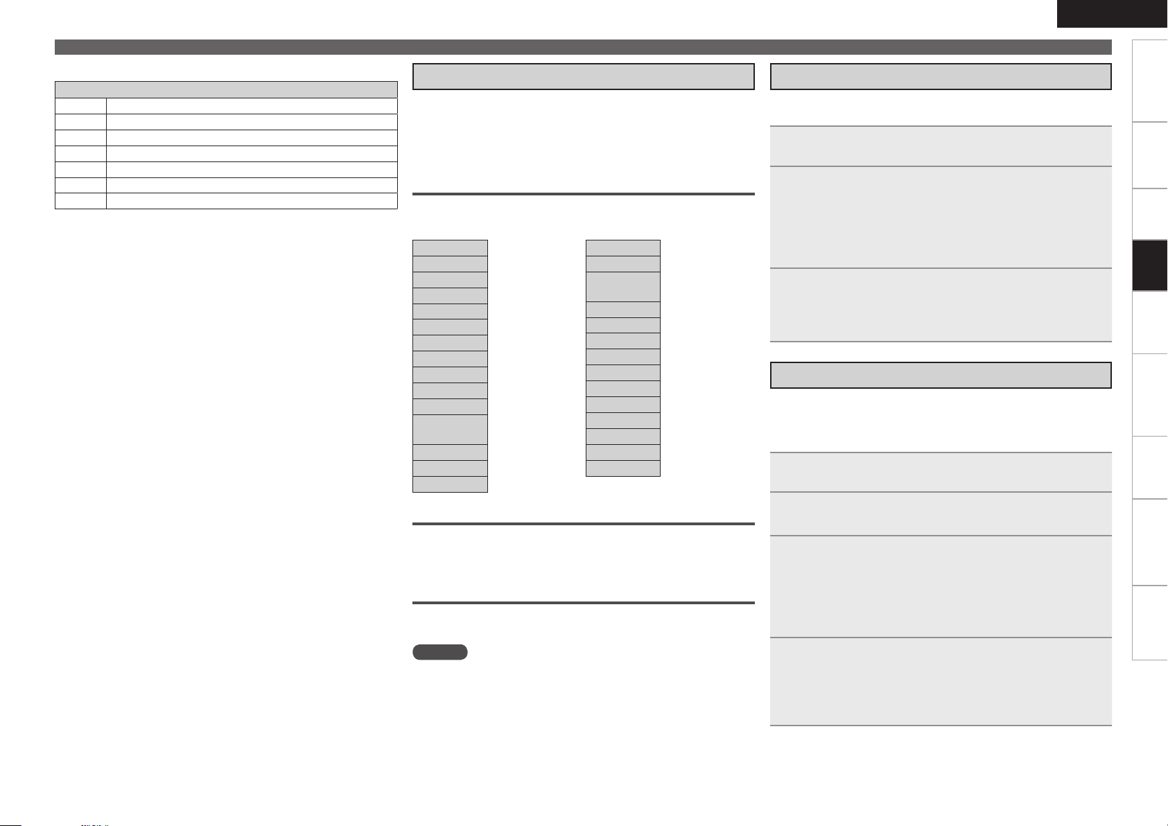
Default settings
n
Auto tuner presets
A1 ~ A8 87.5 / 89.1 / 98.1 / 108.0 / 90.1 / 90.1 / 90.1 / 90.1 MHz
B1 ~ B8 522 / 603 / 999 / 1404 / 1611 kHz, 90.1 / 90.1 / 90.1 MHz
C1 ~ C8 90.1 MHz
D1 ~ D8 90.1 MHz
E1 ~ E8 90.1 MHz
F1 ~ F8 90.1 MHz
G1 ~ G8 90.1 MHz
RDS (Radio Data System)
RDS (works only on the FM band) is a broadcasting service which
allows a station to send additional information along with the regular
radio program signal.
The following three types of RDS information can be received with
this unit:
Program Type (PTY)
PTY identifies the type of RDS program.
The program types and their displays are as follows:
NEWS News
AFFAIRS Current Affairs
INFO Information
SPORT Sports
EDUCATE Education
DRAMA Drama
CULTURE Culture
SCIENCE Science
VARIED Varied
POP M Pop Music
ROCK M Rock Music
EASY M
LIGHT M Light Classical
CLASSICS Serious Classical
OTHER M Other Music
Easy Listening
Music
Traffic Program (TP)
TP identifies programs that carry traffic announcements.
This allows you to easily find out the latest traffic conditions in your
area before leaving home.
Radio Text (RT)
RT allows RDS stations to send text messages that appear on the
display.
NOTE
The operations described below using [SEARCH] will not function in
areas in which there are no RDS broadcasts.
WEATHER Weather
FINANCE Finance
CHILDREN
SOCIAL Social Affairs
RELIGION Religion
PHONE IN Phone In
TRAVEL Travel
LEISURE Leisure
JAZZ Jazz Music
COUNTRY Country Music
NATION M National Music
OLDIES Oldies Music
FOLK M Folk Music
DOCUMENT Documentary
Children’s
programmes
ENGLISH
Tuning in Radio Stations
RDS Search
Use this function to automatically tune to FM stations that provide the
RDS service.
Press [SEARCH] to select “RDS”.
1
Press [CHANNEL].
2
The search for RDS stations begins automatically.
If no RDS stations are found with the above operation, all the
b
reception bands are searched.
When a broadcast station is found, that station’s name appears
b
on the display.
To continue searching, repeat steps 1 to 2.
3
If no RDS station is found when all the frequencies have been
b
searched, “NO RDS” is displayed.
PTY Search
Use this function to find RDS stations broadcasting a designated
program type (PTY).
For a description of each program type, refer to “Program Type
(PTY)”.
Press [SEARCH] twice to select “PTY”.
1
Watching the display, press ui to call out the
2
desired program type.
Press [CHANNEL].
3
PTY search begins automatically.
If there is no station broadcasting the designated program type
b
with the above operation, all the reception bands are searched.
The station name is displayed on the display after searching
b
stops.
To continue searching, repeat steps 1 to 3.
4
If no station broadcasting the designated program type is found
b
when all the frequencies have been searched, “NO PROGRAMME”
is displayed.
Getting Started Connections Settings Remote ControlMulti-zone Information Troubleshooting Specifications
Playback
Page 58

ENGLISH
o p
[SEARCH]
[CHANNEL]
op
Getting Started Connections Settings Remote ControlMulti-zone Information Troubleshooting Specifications
Playback
Tuning in Radio Stations
Symbols used to indicate buttons in this manual
Button located on both the main unit
and the remote control unit
Button only on the main unit
Button only on the remote control unit
Front
BUTTON
<BUTTON>
[BUTTON]
TP Search
Use this function to find RDS stations broadcasting traffic programs
(TP stations).
Press [SEARCH] three times to select “TP”.
1
Press [CHANNEL].
2
TP search begins automatically.
If no TP station is found with the above operation, all the reception
b
bands are searched.
The station name is displayed on the display after searching
b
stops.
To continue searching, repeat steps 1 to 2.
3
If no other TP station is found when all the frequencies have been
b
searched, “NO PROGRAMME” is displayed.
RT (Radio Text)
“RT” appears on the display when radio text data is received.
Press [SEARCH] four times to select “RT”.
While receiving an RDS broadcast station, the text data broadcast
b
from the station is displayed.
To turn the display off, press o p.
b
If no text data is being broadcast, “NO TEXT DATA” is displayed.
b
Playing Network Audio, USB
Memory Devices
This procedure can be used to play Internet radio stations or music
or still picture (JPEG) files stored on a computer or USB memory
device.
Important Information
About the Internet Radio Function
Internet radio refers to radio broadcasts distributed over the Internet.
•
Internet radio stations from around the world can be tuned in.
The AVR-3310 is equipped with the following Internet radio
functions:
Stations can be selected by genre and region.
•
Up to 56 Internet radio stations can be preset.
•
Internet radio stations in MP3 and WMA (Windows Media Audio)
•
format can be listened to.
Your favorite radio stations can be registered by accessing an
•
exclusive DENON Internet radio URL from a Web browser on a
computer.
The function is managed for individual users, so you must provide
b
your MAC or e-mail address.
Exclusive URL: http://www.radiodenon.com
The radio station database service may be suspended without
b
notice.
The AVR-3310’s Internet radio station list is created using a radio
•
station database service (vTuner). This database service provides a
list edited and created for the AVR-3310.
Page 59

Media Player
This function lets you play music files and playlists (m3u, wpl) stored on
a computer (media server) connected to the AVR-3310 via a network.
With the AVR-3310’s network audio playback function, connection to
the server is possible using one of the technologies below.
Windows Media Player Network Sharing Service
•
Windows Media DRM10
•
Album Art Function
n
When a WMA (Windows Media Audio), MP3 or MPEG-4 AAC file
includes album art data, the album art can be displayed while the
music files are playing.
For music files in WMA (Windows Media Audio) format, the album
art is only played when using Windows Media Player ver. 11.
Slide Show Function
n
Still picture (JPEG) files stored in folders on a media server can be
played as slide shows. The time for which each picture is displayed
can be set.
When still picture (JPEG) files are played on the AVR-3310, they
are played in the direction in which they are stored in the folder, so
store in them in the direction in which you want them to play.
USB Memory Devices
A USB memory device can be connected to the AVR-3310’s USB port
to play music and still picture (JPEG) files stored on the USB memory
device.
Only USB memory devices conforming to mass storage class and
•
MTP (Media Transfer Protocol) standards can be played on the AVR-
3310.
The AVR-3310 is compatible with USB memory devices in “FAT16”
•
or “FAT32” format.
Album Art Function
n
When an MP3 music file includes album art data, the album art can
be displayed while playing the file.
Slide Show Function
n
Still picture (JPEG) files stored on USB memory devices can be
played as slide shows.
The time for which each picture is displayed can be set.
When still picture (JPEG) files are played on the AVR-3310, they
are played in the direction in which they are stored in the folder, so
store in them in the direction in which you want them to play.
GCompatible formatsH
Internet radio
WMA (Windows
Media Audio)
MP3 (MPEG-1
Audio Layer-3)
WAV –
MPEG-4 AAC –
FLAC (Free
Lossless Audio
Codec)
JPEG –
A server or server software compatible with distribution in the
corresponding formats is required to play music files via a network.
z
1 : Media server and USB
The AVR-3310 is compatible with MP3 ID3-Tag (Ver. 2)
•
standards.
The AVR-3310 is compatible with WMA META tags.
•
WAV format Quantization bit rate: 16 bits.
•
z
2 : Only files that are not protected by copyright can be played on
the AVR-3310.
Contents downloaded from pay sites on the Internet are copyright
protected. Also, files encoded in WMA format when ripped from
a CD, etc., on a computer may be copyright protected, depending
on the computer’s settings.
z
3 : Copyright-protected files can be played on certain portable
players compatible with MTP.
S S S
S S S
–
Media
serverz1
S S
S
S S
S S
z
2
USB memory
devicesz1
z
3
z
S
2
ENGLISH
Playing Network Audio, USB Memory Devices
GCompatible formatsH
Sampling
frequency
WMA (Windows
Media Audio)
MP3 (MPEG-1
Audio Layer-3)
WAV 32/44.1/48kHz – .wav
MPEG-4 AAC 32/44.1/48kHz 16 ~ 320kbps
FLAC (Free
Lossless Audio
Codec)
32/44.1/48kHz 48 ~ 192kbps .wma
32/44.1/48kHz 32 ~ 320kbps .mp3
32/44.1/48kHz – .flac
About Napster
Napster is a monthly subscription music distribution service provided
by Napster. This service allows users to download and play pieces
of music they want to hear on the AVR-3310. Before you can use
Napster, you will need to visit the Napster website on your PC to
create an account and register as a member. For details, access the
following site:
http://www.napster.com/choose/index_default.html
Bit rate Extension
.aac/
.m4a/
.mp4
Getting Started Connections Settings Remote ControlMulti-zone Information Troubleshooting Specifications
Playback
Page 60

ENGLISH
uio p
<STATUS>
ENTER
[DEVICE
SELECT 1]
[DEVICE
SELECT 2]
[SOURCE
SELECT]
[NET/USB]
[1]
uiop
ENTER
[SHIFT]
[MEMORY]
[CHANNEL]
[NET/USB]
Getting Started Connections Settings Remote ControlMulti-zone Information Troubleshooting Specifications
Playing Network Audio, USB Memory Devices
Symbols used to indicate buttons in this manual
Button located on both the main unit
and the remote control unit
Button only on the main unit
Button only on the remote control unit
Playback
Front Rear
BUTTON
<BUTTON>
[BUTTON]
Listening to Internet Radio
Playback preparation.
q Check the network environment, then turn on the AVR-
1
2
3
4
5
3310’s power (vpage 22 “Connecting to a Home Network
(LAN)”).
w If settings are required, make the “Network Connecting”
(vpage 37).
e Set [DEVICE SELECT 1] to “MAIN/TV” [DEVICE SELECT 2]
to “MAIN”.
Press [SOURCE SELECT] to display the GUI Source
Select menu, then select “ ” (vpage 26).
Press ui to select the item you want to play, then
press ENTER or p.
The station list is displayed.
Press ui to select the station, then press ENTER,
p or [1].
Playback starts once buffering reaches “100%”.
Adjust the items below.
Adjusting the master volume (vpage 62)
n
Selecting the surround mode (vpage 64)
n
Adjusting the Sound and Picture Quality
n
(vpage 67)
There are many Internet radio stations on the Internet, and the
•
quality of the programs they broadcast as well as the bit rate of the
tracks varies widely.
Generally, the higher the bit rate, the higher the sound quality, but
depending on the communication lines and server traffic, the music
or audio signals being streamed may be interrupted. Inversely, lower
bit rates mean a lower sound quality but less tendency for the sound
to be interrupted.
“Server Full” or “Connection Down” is displayed if the station is
•
busy or not broadcasting.
On the AVR-3310, folder and file names can be displayed as
•
titles. Any characters that cannot be displayed are replaced with
“. (period)”.
Use the RESTORER mode to expand the low and high frequency
•
components of compressed audio files and achieve a richer sound
“RESTORER” (vpage 71). The default setting is “Mode 3”.
When <STATUS> is pressed, the display can be switched between
•
the title name and radio station name.
The time (default : 30 sec) for which the GUI menu are displayed
•
can be set at GUI menu “GUI” – “NET/USB” (vpage 41). Press
uio p to return to the original screen.
Recently Played Internet Radio Stations
Recently played internet radio stations can be selected from “Recently
Played”.
Up to 20 stations stored in “Recently Played”.
To stop (vpage 62)
n
Searching pages (vpage 63)
n
Searching by first letter (vpage 63)
n
Press ui to select “Recently Played”, then press
1
ENTER or p.
Press ui to select the item you want to play, then
2
press ENTER, p or [1].
Page 61

Search Stations by Keyword (Alphabetic Strings)
Enter St ation
Search b y Keyword
SubmitInput
Press ui to select “Search by Keyword”, then press
1
ENTER or p.
The search display appear.
Enter the characters, then press ENTER.
2
Presetting Internet Radio Stations
Preset Internet radio stations can be selected directly.
While the Internet radio station you want to preset is
1
playing, press [MEMORY].
Press ui to select “Preset”, then press ENTER.
2
Press [SHIFT], then press [CHANNEL] to select the
3
desired preset number.
Press [MEMORY] again to complete the setting.
4
The Internet radio station is now preset.
NOTE
If registered at a number that has already been preset, the previously
registered setting is cleared.
Listening to Preset Internet Radio Stations
After pressing [SHIFT], press [CHANNEL] to select the
registered preset number.
The AVR-3310 automatically connects to the Internet and playback
begins.
Registering Internet Radio Stations as Your
Favorites
Favorites are listed at the top of the menu screen, so when a station
is registered as a favorite it can be tuned in easily.
Press [MEMORY] while the Internet radio station you
1
want to register is playing.
Press ui to select “Favorites”, then press ENTER.
2
Press o to select “Add”.
3
The Internet radio station is registered.
If you do not want to register it, press p.b
Listening to Internet Radio Stations Registered in
Your Favorites
Press [SOURCE SELECT] to display the GUI Source
1
Select menu, then select “ ” (vpage 26).
Press ui to select the Internet radio station, then
2
press ENTER, p or [1].
The AVR-3310 automatically connects to the Internet and
playback begins.
Playing Network Audio, USB Memory Devices
Clearing Internet Radio Stations from Your
Favorites
Press [SOURCE SELECT] to display the GUI Source
1
Select menu, then select “ ” (vpage 26).
Press ui to select the Internet radio station you
2
want to clear, then press [MEMORY].
Press o to select “Remove”.
3
The selected Internet radio station is cleared.
To cancel the operation without clearing the station, press p.b
ENGLISH
Getting Started Connections Settings Remote ControlMulti-zone Information Troubleshooting Specifications
Playback
Page 62

ENGLISH
ui p
<STATUS>
ENTER
[DEVICE
SELECT 1]
[DEVICE
SELECT 2]
[SOURCE
SELECT]
[NET/USB]
[1]
uip
ENTER
[TU 6]
[TU 7]
[NET/USB]
[USB]
Getting Started Connections Settings Remote ControlMulti-zone Information Troubleshooting Specifications
Playback
Playing Network Audio, USB Memory Devices
Symbols used to indicate buttons in this manual
Button located on both the main unit
and the remote control unit
Button only on the main unit
Button only on the remote control unit
Front Rear
BUTTON
<BUTTON>
[BUTTON]
Playing Files Stored on a Computer
Use this procedure to play music files, image files or playlists.
Playback preparation.
1
q Check the network environment, then turn on the AVR-
3310’s power (vpage 22 “Connecting to a Home
Network (LAN)”).
w If settings are required, make the “Network Connecting”
(vpage 37).
e Prepare the computer (vComputer’s operating
instructions).
r Set [DEVICE SELECT 1] to “MAIN/TV” [DEVICE SELECT 2]
to “MAIN”.
Press [SOURCE SELECT] to display the GUI Source
2
Select menu, then select “ ” (vpage 26).
Use ui to select the server including the le to be
3
played, then press ENTER or p.
Press ui to select the search item or folder, then
4
press ENTER or p.
Press
ui
5
or [1]
.
Playback starts once buffering reaches “100%”.
Adjust the items below.
to select the le, then press
6
Adjusting the master volume (vpage 62)
n
Selecting the surround mode (vpage 64)
n
Adjusting the Sound and Picture Quality
n
(vpage 67)
ENTER, p
To stop (vpage 62)
n
Stopping playback temporarily (vpage 62)
n
Selecting tracks (vpage 63)
n
Playing repeatedly (vpage 63)
n
Playing in random order (vpage 63)
n
Searching pages (vpage 63)
n
Searching by first letter (vpage 63)
n
When playing still picture (JPEG) files, files can also be selected
•
using the operation described below.
During playback, either press [TU 6] (previous file) or [TU 7]
(next file).
Connections to the required system and specific settings must be
•
made in order to play music files (vpage 22).
Before starting, you must launch the computer’s server software
•
and set the files as server contents. For details, see the operating
instructions of your server software.
Depending on the size of the still picture (JPEG) file, some time may
•
be required for the file to be displayed.
The order in which the tracks/files are displayed depends on the
•
server specifications. If due to the server specifications the tracks/
files are not displayed in alphabetical order, searching by the first
letter may not work properly.
WMA Lossless files can be played when using a server supporting
•
transcoding, such as Windows Media Player Ver. 11.
Use the RESTORER mode to expand the low and high frequency
•
components of compressed audio files and achieve a richer sound
(vpage 71). The default setting is “Mode 3”.
The time (default : 30 sec) for which the GUI menus are displayed
•
can be set at “GUI” – “NET/USB” (vpage 41).
Use <STATUS> to switch between displaying the title name, artist
•
name or album name.
Sub remote control unit
Page 63

Playing files that have been Preset or Registered in
Your Favorites
Files can be preset, registered in your favorites and played using the
same operations as for Internet radio stations (vpage 57).
NOTE
Presettings are erased by overwriting them.
•
When the operation described below is performed, the media
•
server’s database is updated and it may no longer be possible to
play preset or favorite music files.
When you quit the media server and then restart it.
•
When music files are deleted or added on the media server.
•
Playing Files Stored on USB Memory
Devices
Only USB memory devices conforming to mass storage class and
MTP (Media Transfer Protocol) standards can be played on the AVR-
3310.
Playback preparation.
1
q Connect the USB memory device to the USB port.
w Set [DEVICE SELECT 1] to “MAIN/TV” [DEVICE SELECT 2]
to “MAIN”.
Press [SOURCE SELECT] to display the GUI Source
2
Select menu, then select “ ” (vpage 26).
Press ui to select the search item or folder, then
3
press ENTER or p.
Press ui to select the le, then press ENTER, p
4
or [1].
Playback starts once buffering reaches “100%”.
Adjust the items below.
5
Adjusting the master volume (vpage 62)
n
Selecting the surround mode (vpage 64)
n
Adjusting the Sound and Picture Quality
n
(vpage 67)
ENGLISH
Playing Network Audio, USB Memory Devices, Listening to Napster
Depending on the size of the still picture (JPEG) file, some time may
•
be required for the file to be displayed.
During playback of still picture (JPEG) files, the files can also be
•
switched using [TU 6] (previous file) and [TU 7] (next file).
If the USB memory device is divided into multiple partitions, only the
•
top partition can be selected.
The AVR-3310 is compatible with MP3 files conforming to “MPEG-1
•
Audio Layer-3” standards.
When [USB] on the sub remote control unit is pressed, playback
•
starts from the first file stored on the USB memory device.
NOTE
DENON will accept no responsibility whatsoever for any loss or
•
damage to data on USB memory devices when using the USB
memory device connected to the AVR-3310.
USB memory devices will not work via a USB hub.
•
DENON does not guarantee that all USB memory devices will
•
operate or receive power. When using a portable USB connection
type HDD of the kind to which an AC adapter can be connected to
supply power, use the AC adapter.
It is not possible to connect and use a computer via the AVR-3310’s
•
USB port using a USB cable.
The AVR-3310 is not compatible with the iPod shuffle.
•
Getting Started Connections Settings Remote ControlMulti-zone Information Troubleshooting Specifications
Playback
To stop (vpage 62)
n
Stopping playback temporarily (vpage 62)
n
Selecting tracks (vpage 63)
n
Playing repeatedly (vpage 63)
n
Playing in random order (vpage 63)
n
Searching pages (vpage 63)
n
Searching by first letter (vpage 63)
n
Page 64
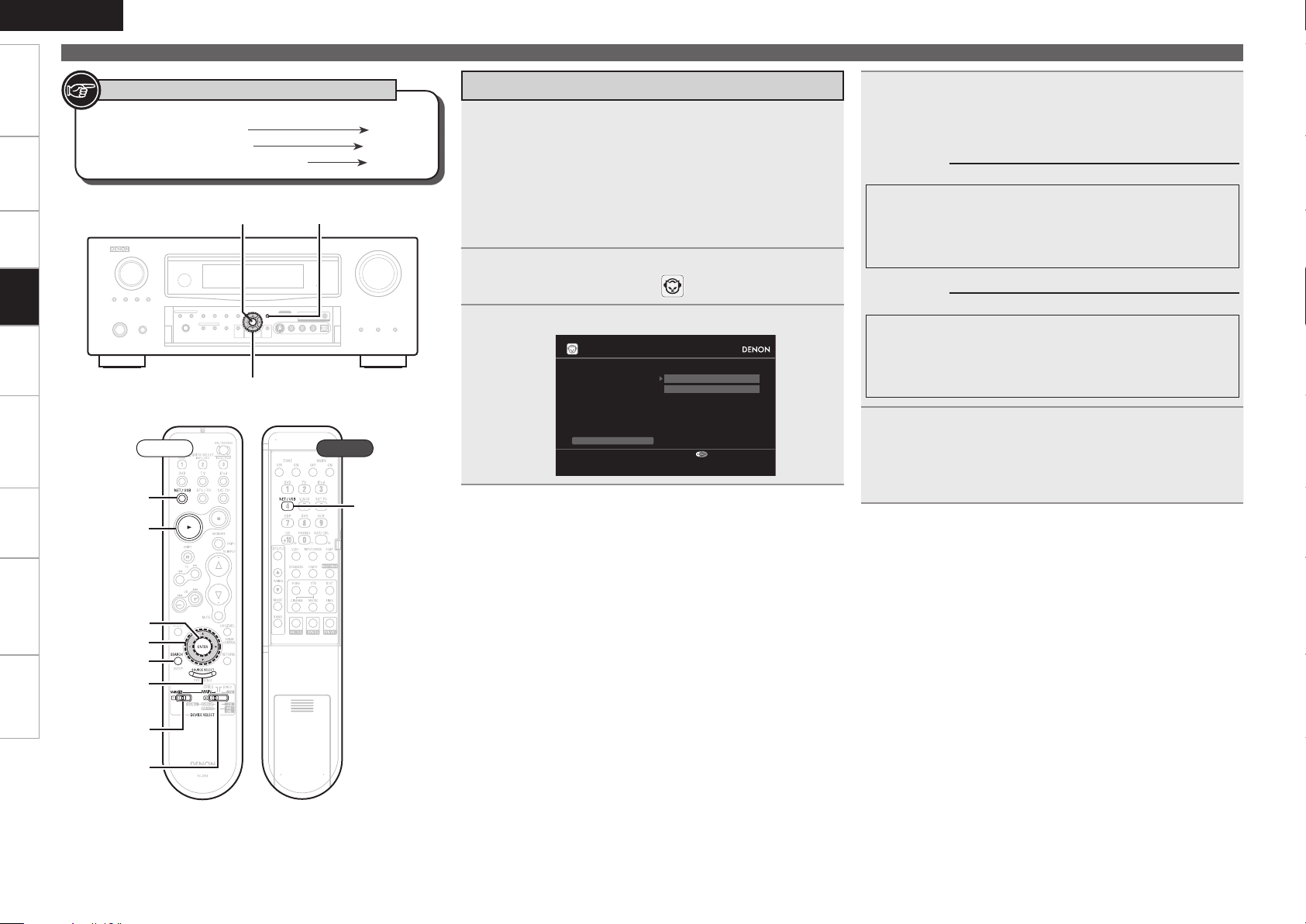
ENGLISH
Napster Account
OK
Enter U sername
Usernam e
Passwor d
Cancel
ui p
<STATUS>
ENTER
[DEVICE
SELECT 1]
[DEVICE
SELECT 2]
[SOURCE
SELECT]
[NET/USB]
[1]
uip
ENTER
[SEARCH]
[NET/USB]
Getting Started Connections Settings Remote ControlMulti-zone Information Troubleshooting Specifications
Listening to Napster
Symbols used to indicate buttons in this manual
Button located on both the main unit
and the remote control unit
Button only on the main unit
Button only on the remote control unit
Playback
BUTTON
<BUTTON>
[BUTTON]
Listening to Napster
Playback preparation.
1
q Check the network environment, then turn on the AVR-
3310’s power (vpage 22 “Connecting to a Home Network
(LAN)”).
w If settings are required, make the “Network Connecting”
(vpage 37).
e Set [DEVICE SELECT 1] to “MAIN/TV” [DEVICE SELECT 2] to
“MAIN”.
Press [SOURCE SELECT] to display the GUI Source
2
Select menu, then select “ ” (vpage 26).
Use ui p to input “Username” and “Password”.
3
After inputting the “Username” and “Password”,
4
select “OK”, then press ENTER.
If the “Username” and “Password” match, the top menu for
Napster is displayed.
Username :
n
[Input characters]
GLower case charactersH abcdefghijklmnopqrstuvwxyz
GUpper case charactersH ABCDEFGHIJKLMNOPQRSTUVWXYZ
GSymbolsH ! “ # $ % & ’ ( ) * + , - . / : ; < = > ? @ [ \ ] ˆ _ ` { | } ˜
(Space)
GNumbersH 0123456789
Password :
n
[Input characters]
GLower case charactersH abcdefghijklmnopqrstuvwxyz
GUpper case charactersH ABCDEFGHIJKLMNOPQRSTUVWXYZ
GSymbolsH ! “ # $ % & ’ ( ) * + , - . / : ; < = > ? @ [ \ ] ˆ ` { | } ˜
(Space)
GNumbersH 0123456789
Adjust the items below.
5
Adjusting the master volume (vpage 62)
Front Rear
n
Selecting the surround mode (vpage 64)
n
Adjusting the Sound and Picture Quality
n
(vpage 67)
0
Page 65
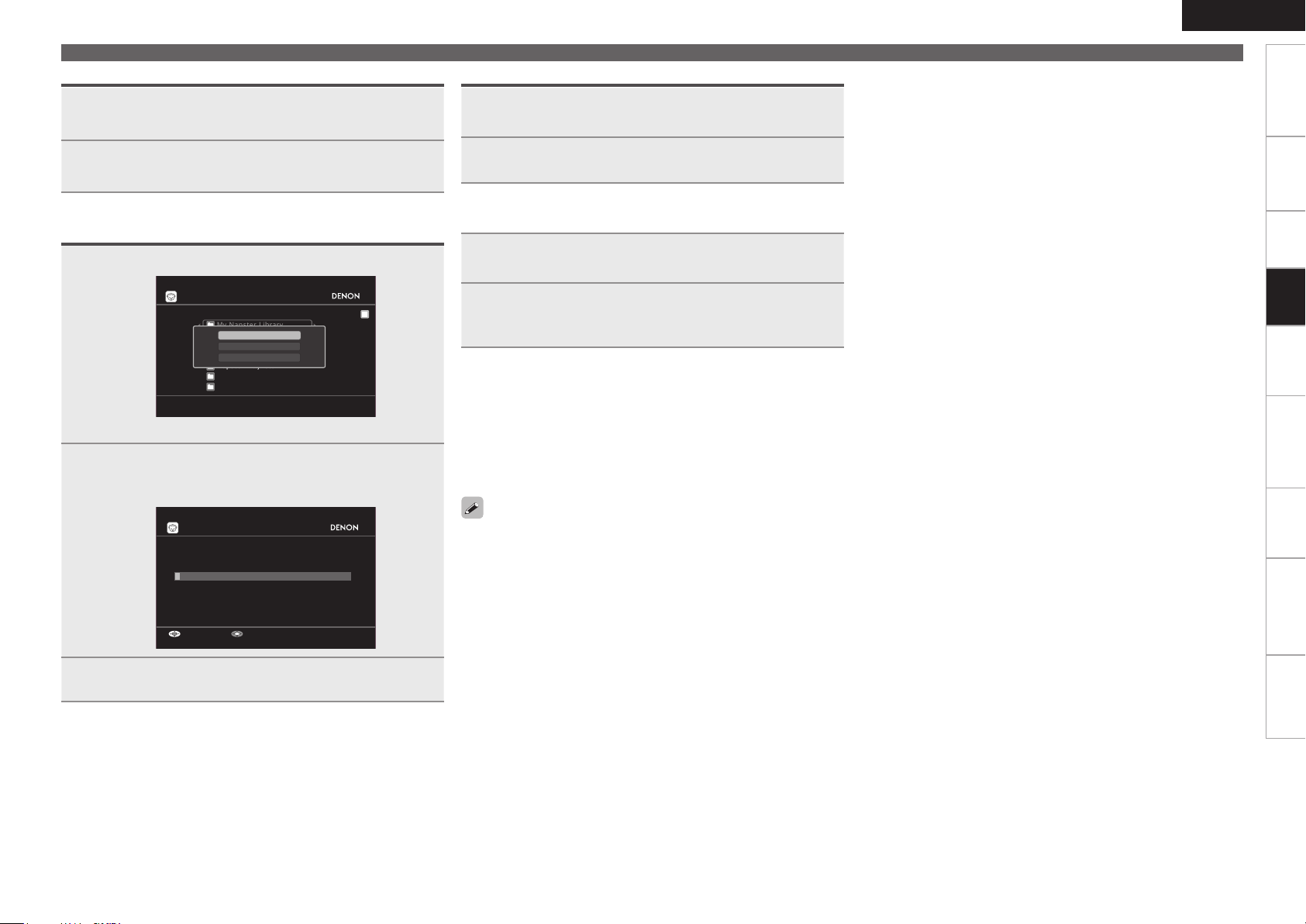
My Naps ter Library
Top 100 s
New Rel eases
Radio
Napster Playlists
Staff P icks
Genres
[1/7]
Napster
Search by Artist
Search by Arbums
Search by Track
Enter A rtist Name
Search by Artist
SubmitInput
Search From Napster Menu
Registering Tracks in My Napster Library
ENGLISH
Listening to Napster
Getting Started Connections Settings Remote ControlMulti-zone Information Troubleshooting Specifications
Use ui to select search item or folder, then press
1
ENTER or p.
Use ui to select the track item, then press ENTER
2
or p.
Enter a Character Search For the Track You Want
to Listen to
Press [SEARCH].
1
You can search by artist name, album name or track name.b
Use ui to select the search item, then press
2
ENTER.
The search display appears.
Press p while the track you wish to register is
1
playing.
Select “Add to my library”, then press ENTER or p.
2
The track is entered in the Library.
Listening to Tracks Registered In My Napster
n
Library
Use ui to select “My Napster Library”, then press
1
ENTER or p.
Use ui to select the information or track, then
2
press ENTER, p or [1].
After selecting, the information is displayed.
To stop (vpage 62)
n
Selecting tracks (vpage 63)
n
Playing repeatedly (vpage 63)
n
Playing in random order (vpage 63)
n
Searching pages (vpage 63)
n
Use the RESTORER mode to expand the low and high frequency
•
components of compressed audio files and achieve a richer sound
(vpage 71). The default setting is “Mode 3”.
The time (default : 30 sec) for which the GUI menus are displayed
•
can be set at “GUI” – “NET/USB” (vpage 41).
Use <STATUS> to switch between displaying the title name, artist
•
name or album name.
Playback
3
Enter the characters, then press ENTER.
Page 66
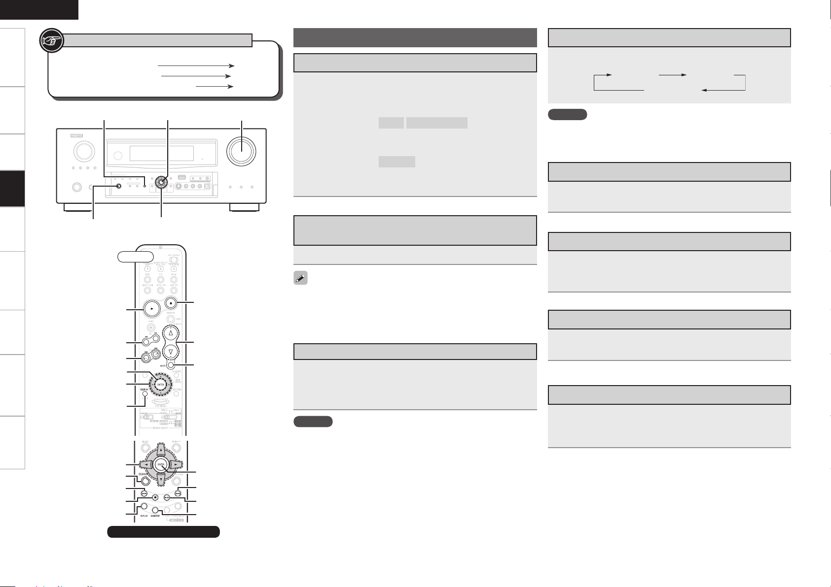
ENGLISH
uio p
ENTER<FRONT SPEAKERS> MASTER VOLUME
uiop
ENTER
[SEARCH]
[MUTE]
MASTER
VOLUME
[8, 9]
[6, 7]
[2]
[1]
[REPEAT]
[2]
[1/3]
[RANDOM]
[SEARCH]
uio
p
[8]
[9]
ENTER
Front A Front B
Front A+B
Getting Started Connections Settings Remote ControlMulti-zone Information Troubleshooting Specifications
Playback
Symbols used to indicate buttons in this manual
Button located on both the main unit
and the remote control unit
Button only on the main unit
Button only on the remote control unit
BUTTON
<BUTTON>
[BUTTON]
Operations During Playback
Adjusting the Master Volume
Use MASTER VOLUME to adjust the volume.
When the “Volume Display” setting (vpage 40) is
n
“Relative”
GAdjustable rangeH
When the “Volume Display” setting (vpage 40) is
n
“Absolute”
GAdjustable rangeH
The adjustable range depends on the input signal, the channel
b
level settings, etc.
– – – –80.5dB ~ 18.0dB
0.0 ~ 99.0
Switching the front speakers
Press <FRONT SPEAKERS>.
NOTE
When you set to “Custom” with “Front Speaker Setup“ (vpage 35),
you cannot operate <FRONT SPEAKERS>.
To Stop
During playback, either press and hold ENTER or press
[2].
PHONES jack
Front
Sub remote control unit
Turning Off the Sound Temporarily
(Muting)
Press [MUTE].
The sound is reduced to the level set at “Mute Level” (vpage
•
40).
To cancel, press [MUTE] again. Muting can also be canceled by
•
adjusting the master volume.
Listening with Headphones
Plug the headphones into the PHONES jack on the main
unit.
The sound from the speakers and pre-out connectors is automatically
cut.
NOTE
To prevent hearing loss, do not raise the volume level excessively
•
when using headphones.
Remove your headphones when performing Audyssey™ Auto Setup
•
or adjusting the speaker volume.
Stopping Playback Temporarily
During playback, press ENTER, [1] or [1/3] on the sub
remote control unit.
Press again to resume playback.
Fast-forwarding or Fast-reversing
During playback, press and hold [6] (fast-reverse) or
[7] (fast-forward), or press and hold ui.
To Cue to the Beginning of a Track
During playback, either press [8] (to search for
previous tracks) or [9] (to search for subsequent
tracks), or press ui.
Page 67
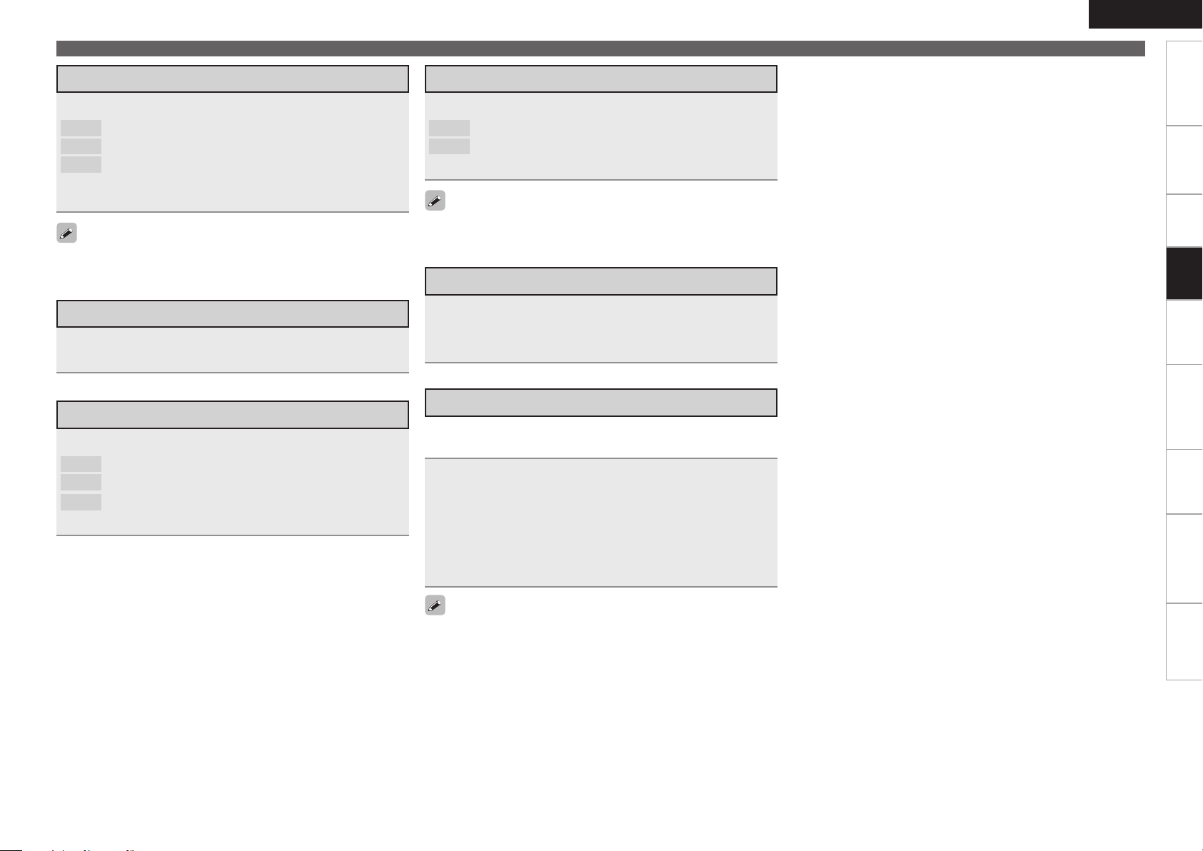
ENGLISH
Operations During Playback
Getting Started Connections Settings Remote ControlMulti-zone Information Troubleshooting Specifications
Playing Repeatedly
Press [REPEAT].
: Repeat all songs.
All
: Repeat the current song.
One
: Disable repeat playback.
OFF
GUI menu “Repeat” (vpage 48, 49) can be set in the same
b
way.
The repeat mode applies when playing tracks on the USB memory
device and on the media server.
Selecting Tracks
During playback, either press u (previous track) or i
(next track).
Shuffling Playback
Press [RANDOM].
: Shuffle songs from current album only.
Albums
: Shuffle all songs.
Songs
: Cancel shuffle mode.
OFF
GUI menu “Shuffle” (vpage 48) can be set in the same way.b
Playing in Random Order
Press [RANDOM].
: Enable random playback.
ON
: Disable random playback.
OFF
GUI menu “Random” (vpage 49) can be set in the same way.b
The random mode applies when playing tracks on the USB memory
device and on the media server.
Searching Pages
Press [SEARCH], then press o (previous page) or p
(next page).
To cancel, press ui or [SEARCH].b
Searching by First Letter
This operation is convenient for choosing items from the menu screens
for Internet radio stations or files stored on the computer.
When the menu screen is displayed, press [SEARCH]
twice, then press o p to select the rst letter you want
to search for.
If there are multiple items starting with the selected letter, they are
•
displayed in alphabetical order.
If it is not possible to search the list, “unsorted list.” is displayed.
•
To cancel, press ui or [SEARCH].
b
Playback
If the list is not in alphabetical order, you may not be able to perform
a character search.
Page 68
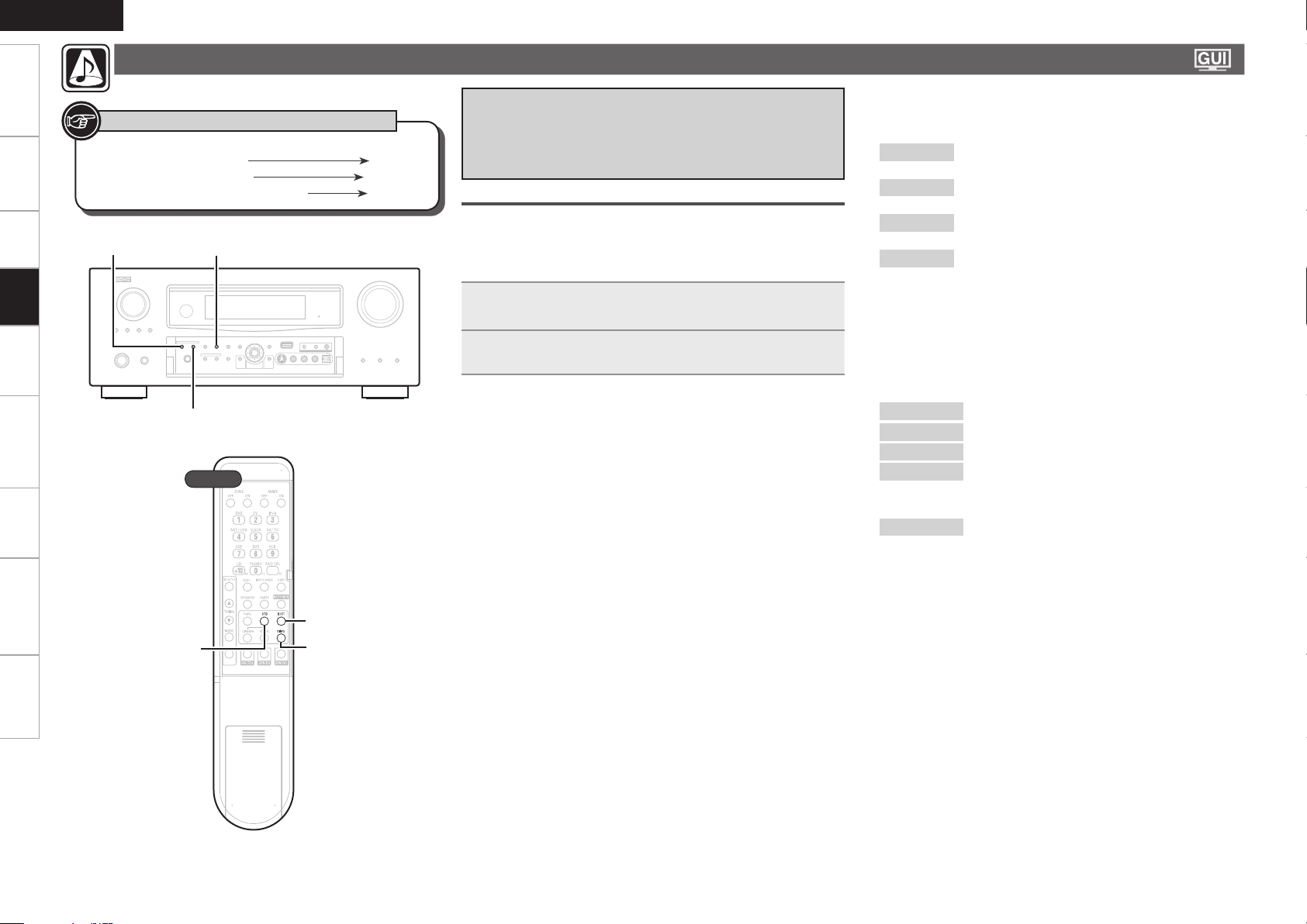
ENGLISH
DSP SIMULATION
DIRECT/STEREO
STANDARD
DSP
SIMULATION
DIRECT/STEREO
STANDARD
Getting Started Connections Settings Remote ControlMulti-zone Information Troubleshooting Specifications
Playback
Selecting the Surround Mode
Symbols used to indicate buttons in this manual
Button located on both the main unit
and the remote control unit
Button only on the main unit
Button only on the remote control unit
Rear
<BUTTON>
[BUTTON]
BUTTON
q Playing Sources According to the
Sources’ Audio Signal Format/
Number of Channels
(Standard Playback)
Operations
The selectable surround modes depend on the following:
Format of the audio signals being input
•
Number of channels of the audio signals being input
•
The set amplifier assignment (vpage 33)
•
Playing the source (vpage 50).
1
Press STANDARD to select the surround mode.
2
Surround Playback of 2-channel Sources
n
q The mode switches as shown below each time STANDARD is
pressed.
DOLBY PLgz
DOLBY PLgx
DOLBY PLg
DTS NEO:6
z1 : This can be set when “Amp Assign” is set to “Front Height” and
“Speaker Configuration” – “Front Height” is set to something
other than “None”.
z2 : This can be set when “Amp Assign” is set to “Normal” and
“Speaker Configuration” – “Surround Back” is set to something
other than “None”.
w Select the mode for the source at “Mode” (vpage 67).
Cinema
Music
Game
Pro Logic
Height
b
The modes that can be selected depend on the input source being
played.
z1
: The signals are decoded in DOLBY PL
playback.
z2
: The signals are decoded in DOLBY PL
playback.
: The signals are decoded in DOLBY PL
playback.
: The signals are decoded in DTS NEO:6 for
playback.
: This mode is suited for movie sources.
: This mode is suited for music sources.
: This mode is suited for games.
: This is the Pro Logic playback mode. This can
be selected when playing with a DOLBY PLg
decoder.
: This is the Front Height playback mode. Set
“Front Height” to “ON” (vpage 68).
gz for
gx for
g for
Page 69
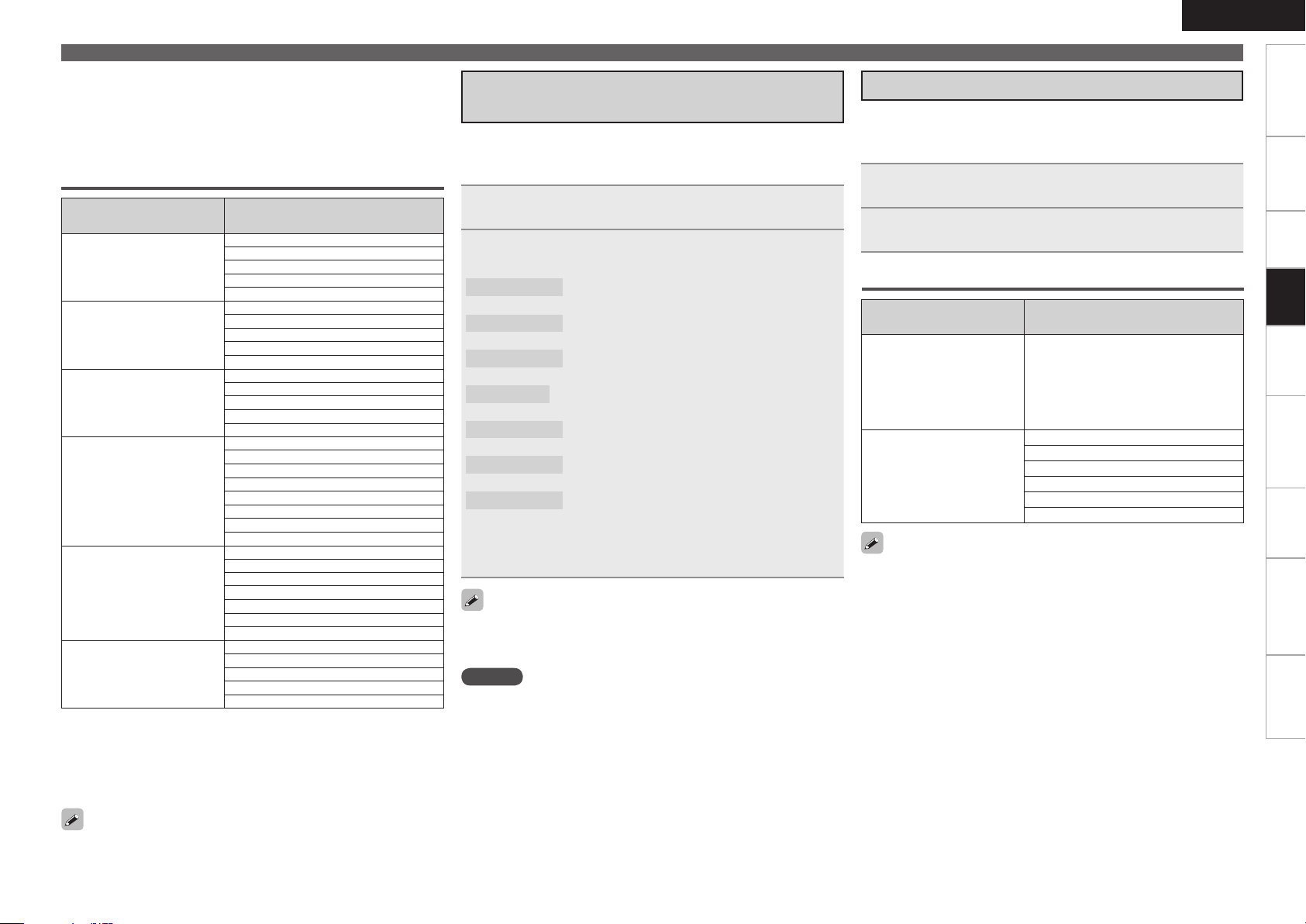
Surround Playback of Multi-channel Sources
n
(Dolby Digital, DTS, etc.)
In the case of standard playback of multi channel sources, the AVR3310 recognizes the format of the multi-channel audio input signal
and automatically operates the appropriate decoder for surround
sound.
Displaying the Currently Playing Surround Mode
Input signal
DOLBY DIGITAL
(other than 2ch) /
DOLBY DIGITAL EX
DOLBY DIGITAL Plus (z4)
DOLBY TrueHD (z4)
DTS (5.1ch) /
DTS-ES Discrete 6.1 /
DTS-ES Matrix 6.1 /
DTS 96/24
DTS-HD (z4)
PCM (multi ch)
z1 : This is displayed when the input signal is “DTS-ES Matrix 6.1”
and the AVR-3310’s “AFDM” setting is set to “ON”
z2 : This is displayed when the input signal is “DTS-ES Discrete
6.1”.
z3 : This is displayed when the input signal is “DTS 96/24”.
z4 : When a signal is input, the HD AUDIO indicator lights.
For details, see page 94, 95.
The indication contents of the
display
DOLBY DIGITAL
DOLBY DIGITAL EX
DOLBY DIGITAL+PLgx CINEMA
DOLBY DIGITAL+PLgx MUSIC
DOLBY DIGITAL+PLgz HEIGHT
DOLBY DIGITAL+
DOLBY DIGITAL+ +EX
DOLBY DIGITAL+ + PLgx CINEMA
DOLBY DIGITAL+ + PLgx MUSIC
DOLBY DIGITAL+ + PLgz HEIGHT
DOLBY TrueHD
DOLBY TrueHD+EX
DOLBY TrueHD+PLgx CINEMA
DOLBY TrueHD+PLgx MUSIC
DOLBY TrueHD+PLgz HEIGHT
DTS SURROUND
DTS+PLgx CINEMA
DTS+PLgx MUSIC
DTS+PLgz HEIGHT
DTS+NEO:6
DTS ES MTRX6.1 (z1)
DTS ES DSCRT6.1 (z2)
DTS 96/24 (z3)
DTS-HD HI RES
DTS-HD MSTR
DTS-HD+NEO:6
DTS-HD+PLgx CINEMA
DTS-HD+PLgx MUSIC
DTS-HD+PLgz HEIGHT
DTS EXPRESS
MULTI CH IN
MULTI IN+PLgx CINEMA
MULTI IN+PLgx MUSIC
MULTI IN+PLgz HEIGHT
MULTI CH IN 7.1
w Playing in a DENON Original
Surround Mode
The desired mode according to the program source and viewing
situation can be selected from among 7 DENON original surround
modes.
Playing the source (vpage 50).
1
Select the surround mode by pressing DSP
2
SIMULATION.
5CH/7CH STEREO
ROCK ARENA
JAZZ CLUB
MONO MOVIE
VIDEO GAME
MATRIX
VIRTUAL
z : When playing sources recorded in monaural in the “MONO
MOVIE” mode, the sound will be off balance with a single channel
(left or right), so input to both channels.
Depending on the program source being played, it may not be possible
to achieve a satisfactory surround effect. In this case, try other modes
to achieve a sound field suited to your tastes.
NOTE
When the input signal is DOLBY TrueHD, DOLBY DIGITAL Plus,DTSHD or DTS EXPRESS, you cannot select DENON original surround
mode.
: This mode is for enjoying stereo sound from all
speakers.
: This mode is for enjoying the atmosphere of a
live concert in an arena.
: This mode is for enjoying the atmosphere of a
live concert in a jazz club.
z
: This mode is for playing monaural movie sources
with surround sound.
: This mode is suited for achieving surround sound
with video games.
: This mode lets you add a sense of expansion to
stereo music sources.
: This mode is for enjoying surround effects using
only the front speakers or headphones.
ENGLISH
Selecting the Surround Mode
e Direct Playback
In this mode the signals bypass the tone control circuitry for high
quality sound.
The sound is output to the same channels as the input signal.
Playing the source (vpage 50).
1
Press DIRECT/STEREO to select the “DIRECT”.
2
Displaying the Currently Playing Surround Mode
Input signal
Analog signal /
PCM (2ch) /
Dolby Digital source /
DTS source /
Other 2-channel digital
signals
PCM (multi ch)
For details, see page 95.
The indication contents of the
display
DIRECT
MULTI CH DIRECT
MULTI CH DIRECT + Dolby EX
MULTI CH DIRECT + PLgx CINEMA
MULTI CH DIRECT + PLgx MUSIC
MULTI CH DIRECT + PLgz HEIGHT
MULTI CH DIRECT 7.1
Getting Started Connections Settings Remote ControlMulti-zone Information Troubleshooting Specifications
Playback
Page 70
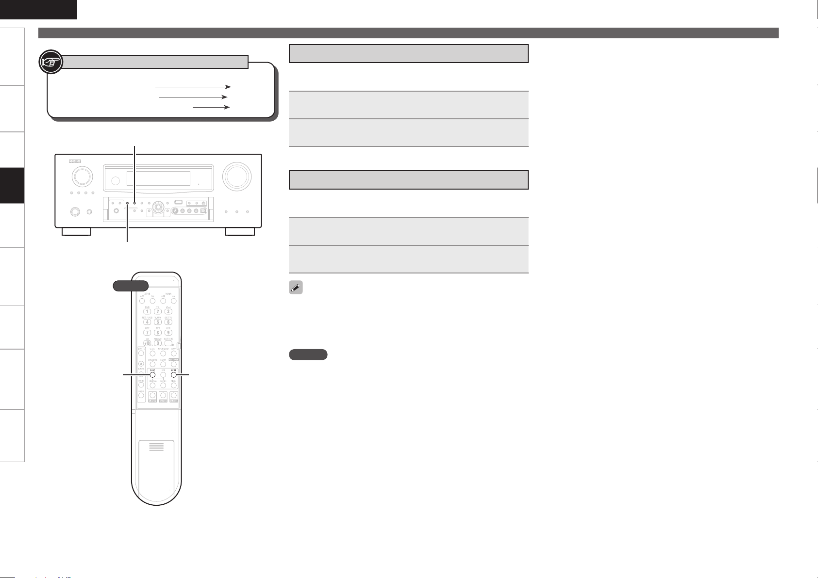
ENGLISH
DIRECT/STEREO
PURE DIRECT
DIRECT/STEREO
PURE DIRECT
Getting Started Connections Settings Remote ControlMulti-zone Information Troubleshooting Specifications
Selecting the Surround Mode
Symbols used to indicate buttons in this manual
Button located on both the main unit
and the remote control unit
Button only on the main unit
Button only on the remote control unit
BUTTON
<BUTTON>
[BUTTON]
r Stereo Playback
This is the mode for playing in stereo. The tone can be adjusted.
Sound is output from the front left and right speakers and subwoofer.
Playing the source (vpage 50).
1
Press DIRECT/STEREO to select the “STEREO”.
2
Playback
t Playing the Pure Direct Mode
This is the mode that recreates the original sound most faithfully,
providing extremely high quality sound.
Playing the source (vpage 50).
1
Press PURE DIRECT.
2
Rear
To cancel, press PURE DIRECT again.
•
During playback in PURE DIRECT mode, the surround parameters
•
are the same as in DIRECT mode.
Video signals are only output when HDMI signals are played in the
•
PURE DIRECT mode.
NOTE
When in the PURE DIRECT mode, the GUI menu display is not
displayed and the display on the main unit is turned off.
Page 71
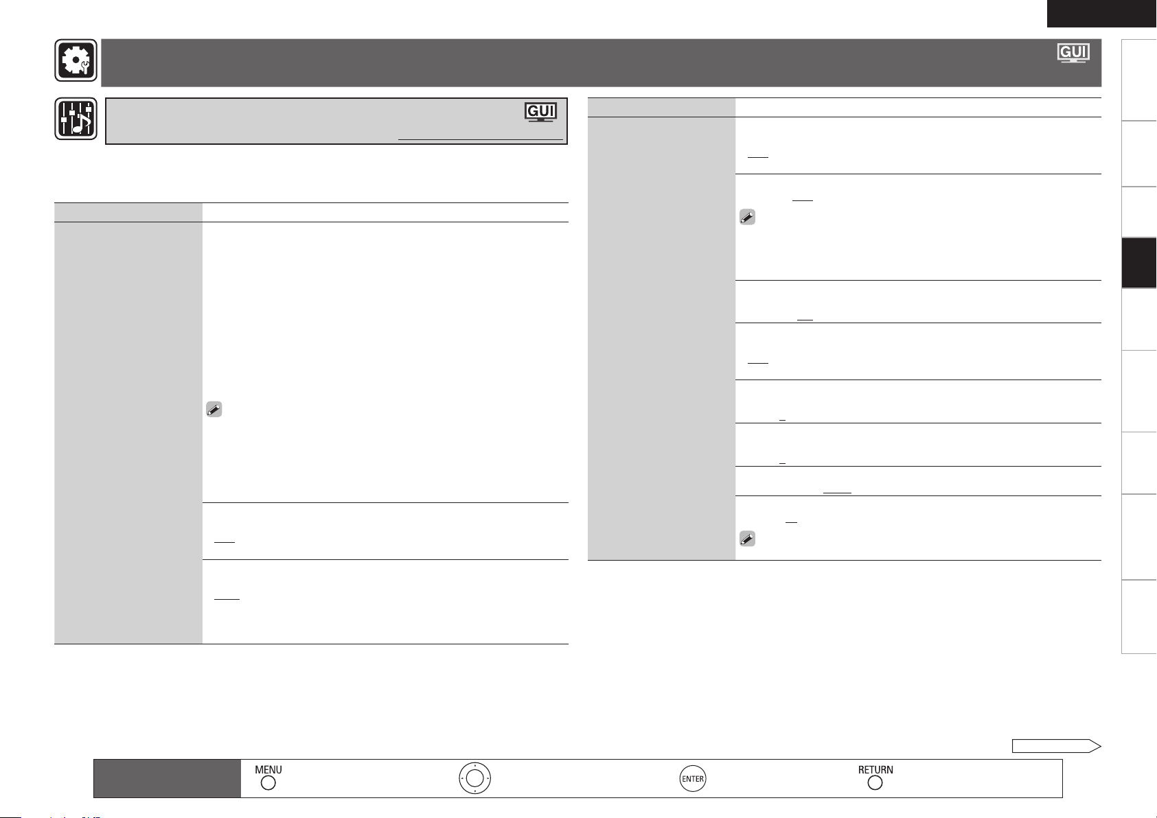
Adjusting the Sound and Picture Quality (Audio/Video Adjust)
For details on how to select, set and cancel settings for each menu, see “GUI Menu Operation” (vpage 25).
ENGLISH
Getting Started Connections Settings Playback Remote ControlMulti-zone Information Troubleshooting Specifications
Adjusting the Sound (Audio Adjust)
Default settings are underlined.
The sound being played in the surround mode can be adjusted to your liking.
The items (parameters) that can be adjusted depend on the signal being input and the currently set surround
mode. For details on the adjustable parameters, see “Surround Modes and Parameters” (vpage 92).
Setting items Setting contents
Surround Parameters
Adjust surround sound
parameters.
Mode : Set the play modes for the different surround modes.
In the PLgx or PLg mode
n
Cinema : Surround sound mode optimized for movie sources.
Music : Surround sound mode optimized for music sources.
Game : Surround sound mode optimized for games.
Pro Logic : Dolby Pro Logic playback mode (PLg mode only).
In the PLgz mode
n
Height : Dolby PLgz Height playback mode.
In the DTS NEO:6 mode
n
Cinema : Surround sound mode optimized for movie sources.
Music : Surround sound mode optimized for music sources.
When “Surround Parameters” – “Front Height” (vpage 68) is set to
•
“ON”, the “Height” mode is set automatically.
The “Music” mode is also effective for movie sources including a lot of
•
stereo music.
The “Cinema” and “Music” modes can also be set by pressing [CINEMA]
•
or [MUSIC].
Cinema EQ : Soften the treble range of movie soundtracks for better
understanding.
OFF : “Cinema EQ” is not used.
•
ON : “Cinema EQ” is used.
•
DRC : Compress dynamic range (difference between loud and soft
sounds).
Auto : Automatic dynamic range compression on/off control according
•
to source. This can be set in the Dolby TrueHD mode.
Low / Middle / High : These set the compression level.
•
OFF : Dynamic range compression always off.
•
Setting items Setting contents
Surround Parameters
(Continued)
D.COMP : Compress dynamic range (difference between loud and soft
sounds).
OFF : Turn dynamic range compression off.
•
Low / Middle / High : These set the compression level.
•
LFE : Adjust the low-frequency effects level (LFE).
–10dB ~ 0dB
•
For proper playback of the different sources, we recommend setting
to the values below.
Dolby Digital sources : “0dB”
•
DTS movie sources : “0dB”
•
DTS music sources : “–10dB”
•
Center Image : Assign center channel signal to front left and right channels
for wider sound.
0.0 ~ 1.0 (0.3)•
Panorama : Assign front L/R signal also to surround channels, for wider
sound.
OFF : Do not set.
•
ON : Set.
•
Dimension : Shift sound image center to front or rear, to adjust playback
balance.
0 ~ 6 (3)•
Center Width : Assign center channel signal to front left and right channels
for wider sound.
0 ~ 7 (3)•
Delay Time : Adjust delay time to control sound stage size.
0ms ~ 300ms (30ms)•
Effect Level : Adjust effect signal level.
1 ~ 15 (10)
•
Set to a lower level if the positioning and sense of phase of the
surround signals seems unnatural.
Playback
Main remote control
operation buttons
:Displaying the menu
Cancel the menu
:Moves the cursor
(Up/Down/Left/Right)
:Confirm the setting :Return to previous menu
See overleaf
Page 72
ENGLISH
Getting Started Connections Settings Remote ControlMulti-zone Information Troubleshooting Specifications
Adjusting the Sound and Picture Quality (Audio/Video Adjust)
Setting items Setting contents
Surround Parameters
(Continued)
Playback
Room Size : Determine size of acoustic environment.
Small : Simulate acoustics of a small room.
•
Medium small : Simulate acoustics of a medium-small room.
•
Medium : Simulate acoustics of a medium room.
•
Medium large : Simulate acoustics of a medium-large room.
•
Large : Simulate acoustics of a large room.
•
NOTE
“Room Size” does not indicate the size of the room in which sources are
played.
Front Height : Set the front height channel.
•
ON : Use the front height channel.
•
OFF : Do not use the front height channel.
•
“Front Height” is not displayed with the settings listed below.
•
When the ”Amp Assign” setting (vpage 33) is set to something
other than “Front Height”
•
When the “Speaker Configuration” – “Front Height” setting (vpage
33) is set to “None”
•
“Front Height” cannot be set if the HD Audio source being played
includes a front height channel. In this case, the Front height channel is
played back without decoding in PLgz mode, using the input signal.
This can also be set by pressing [SPEAKERS].
•
AFDM (Auto flag detect mode) : Detects the source’s surround back
channel signal and sets the optimum surround mode automatically.
OFF : Do not set.
•
ON : Set.
•
[Example] Playing Dolby Digital software (with EX flag)
When “AFDM” is set to “ON”, the surround mode is automatically set
•
to the DOLBY D + PLgx C mode.
To play in the DOLBY DIGITAL EX mode, set “AFDM” to “OFF” and
•
“Surround Back” to “MTRX ON”.
Some Dolby Digital EX sources do not include EX flags. If the playback
•
mode does not switch automatically even when “AFDM” is set to “ON”,
set “Surround Back” to “MTRX ON” or “PLgx CINEMA”.
If the setting in “Speaker Configuration” – “Surround Back” (vpage
•
33) is “None”, “Surround Back” is not displayed.
Setting items Setting contents
Surround Parameters
(Continued)
Surround Back : Sets the method of generating of the surround back
channel.
For 2-channel sources
n
ON : The surround back channel is used.
OFF : No signal is played from the surround back channels.
For multi-channel sources
n
Set the decoding method for the surround back channel.
DSCRT ON : Play the surround back signals included in the 7.1-channel
source.
MTRX ON : Generate and play the surround back signals from the
surround channel signals.
ES MTRXz1 : Generate and play the surround back signals from the
surround channel signals of the DTS source.
ES DSCRTz2 : Play the surround back signals included in the 6.1channel DTS source.
PLgx CINEMAz3 : Generate and play the surround back signals by
decoding the signals in the Dolby Pro Logic gx Cinema mode.
PLgx MUSIC : Generate and play the surround back signals by decoding
the signals in the Dolby Pro Logic gx Music mode.
OFF : The surround back channel is not played.
z1 : This can be selected when playing DTS sources.
z2 : This can be selected when playing DTS sources including a signal
to identify discrete 6.1-channel signals.
z3 : This can be selected when “Speaker Configuration” – “Surround
Back” (vpage 33) is set to “2spkrs”.
This can also be set by pressing STANDARD.
•
If the source being played contains a surround back signal, the decoder
•
type is automatically selected by the AFDM function. Set “AFDM” to
“OFF” to switch to your preferred decoder.
If the setting in “Speaker Configuration” – “Surround Back” (vpage
•
33) is “None”, “Surround Back” is not displayed.
Subwoofer Att. : Attenuate subwoofer level when using EXT. IN input.
ON : Set.
•
OFF : Do not set. Usually use in this mode.
•
Set this to “ON” if the subwoofer channel level seems too high when
playing audio signal.
Main remote control
operation buttons
:Displaying the menu
Cancel the menu
:Moves the cursor
(Up/Down/Left/Right)
:Confirm the setting :Return to previous menu
Page 73
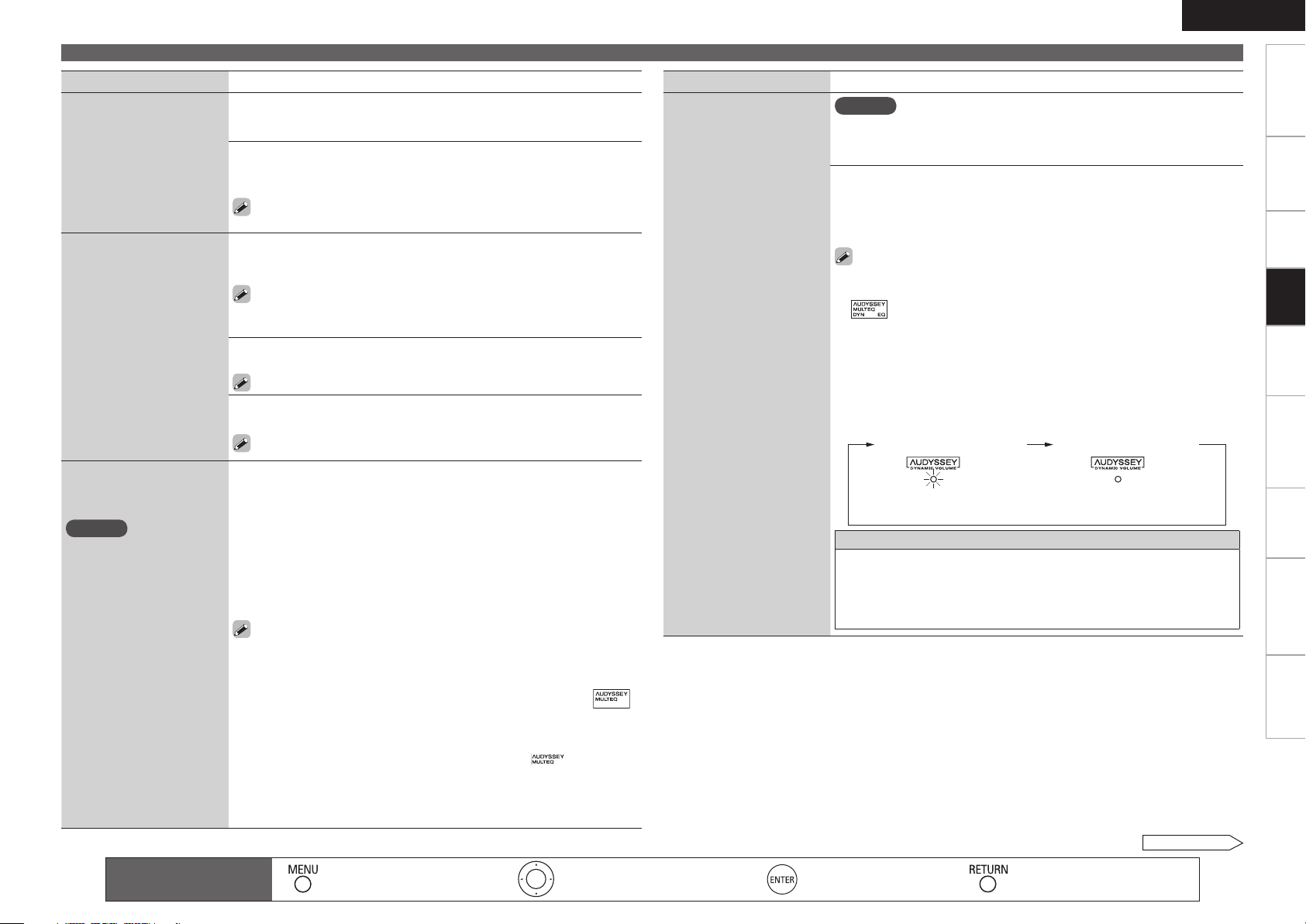
ENGLISH
Dynamic EQ : ON/Volume : OFF
“Green” “OFF”
Dynamic EQ / Volume : OFF
Adjusting the Sound and Picture Quality (Audio/Video Adjust)
Getting Started Connections Settings Remote ControlMulti-zone Information Troubleshooting Specifications
Setting items Setting contents
Surround Parameters
(Continued)
Tone
Adjust the tonal quality of
the sound.
Audyssey Settings
Set MultEQ, Dynamic EQ
and Dynamic Volume.
NOTE
If you have not performed
Auto Setup, or if you change
the speaker settings after
performing Auto Setup, you
may not be able to select
Dynamic EQ/Dynamic
Volume, and “Run Audyssey”
may be displayed.
In this case, either perform
Audyssey Auto Setup over
again or perform “Restore”
(vpage 32) to return to the
settings after Audyssey Auto
Setup was run.
Subwoofer : Turn subwoofer output on and off.
ON : The subwoofer is used.
•
OFF : The subwoofer is not used.
•
Default : Restores all the surround parameter settings to their defaults.
No : Do not reset to the defaults.
•
Yes : Reset to the defaults.
•
If you select “Default” and press ENTER the message “Default
Setting?” is displayed. Select “Yes” or “No”, and then press ENTER.
Tone Control : Sets the tone control function ON and OFF.
ON : Allow tone adjustment (treble, bass).
•
OFF : Playback without tone adjustment.
•
This can be set when “Dynamic EQ” (vpage 69) is set to “OFF”.
•
The tone cannot be adjusted in the direct mode.
•
Bass : Adjust low frequency range (bass).
–6dB ~ +6dB
•
This can be set when “Tone Control” (vpage 69) is set to “ON”.
Treble : Adjust high frequency range (treble).
–6dB ~ +6dB
•
This can be set when “Tone Control” (vpage 69) is set to “ON”.
MultEQ : Corrects both time and frequency response problems in the
listening area.
Audyssey : Optimize the frequency response of all speakers.
•
Audyssey Byp.L/R : Optimize frequency response of speakers except
•
front L and R speakers.
Audyssey Flat : Optimize frequency response of all speakers to flat
•
response.
Manual : Apply frequency response set with “Manual EQ” (vpage
•
71).
OFF : Turn “MultEQ” equalizer off.
•
“Audyssey”, “Audyssey Byp. L/R” and “Audyssey Flat” can be
•
selected after Audyssey Auto Setup has been performed. “Audyssey”
is automatically selected after performing Audyssey Auto Setup. “When
“Audyssey”, “Audyssey Byp. L/R” or “Audyssey Flat” is selected, “ ”
lights.
After running Audyssey Auto Setup, if the Speaker Configuration,
•
Distance, Channel Level, and Crossover Frequency have changed without
increasing the number of speakers measured, only “ ” lights.
If “Dynamic EQ” or “Dynamic Volume” is set to “ON” when “MultEQ”
•
is set to either “OFF” or “Manual”, “MultEQ” is automatically set to
“Audyssey”.
You can also press MULTEQ to set.
•
Setting items Setting contents
Audyssey Settings
(Continued)
NOTE
“MultEQ” and “Manual EQ” cannot be selected when “EQ Customize”
•
is set to “Not Used” (vpage 37).
When using headphones, “MultEQ” is set to “OFF”.
•
Dynamic EQ : Solves the problem of deteriorating sound quality as
volume is decreased by taking into account human perception and room
acoustics.
ON : Use the Dynamic EQ equalizer.
•
OFF : Do not use the Dynamic EQ equalizer.
•
After performing “Audyssey Auto Setup”, the “Dynamic EQ” setting
•
automatically becomes “ON”.
“ ” is displayed when set to “ON”.
•
When “MultEQ” is set to “OFF” or “Manual”, “Dynamic EQ” is
•
automatically set to “OFF”.
If “Dynamic Volume” is set to “ON”, “Dynamic EQ” is automatically
•
set to “ON”.
When you set ”Dynamic EQ” to ”ON”, “Tone Control” is switched
•
”OFF”.
You can also press [DYNAMIC EQ] to set.
•
“Red” “Off”
About Dynamic EQ
Audyssey Dynamic EQ solves the problem of deteriorating sound quality
as volume is decreased by taking into account human perception and
room acoustics. Audyssey Dynamic EQ works in tandem with Audyssey
MultEQ® to provide well-balanced sound for every listener at any volume
level.
Playback
See overleaf
Main remote control
operation buttons
:Displaying the menu
Cancel the menu
:Moves the cursor
(Up/Down/Left/Right)
:Confirm the setting :Return to previous menu
Page 74

ENGLISH
Dynamic EQ / Volume : ON
“Green” “Red”
Dynamic EQ : ON / Volume : OFF
Dynamic EQ / Volume : OFF
Dynamic EQ / Volume : ON
“Green” “Red”
Dynamic EQ : ON / Volume : OFF
Getting Started Connections Settings Remote ControlMulti-zone Information Troubleshooting Specifications
Adjusting the Sound and Picture Quality (Audio/Video Adjust)
Audyssey Settings
(Continued)
Playback
Setting items Setting contents
Reference Level Offset : Audyssey Dynamic EQ is referenced to the
standard film mix level. It makes adjustments to maintain the reference
response and surround envelopment when the volume is turned down
from 0 dB. However, film reference level is not always used in music or
other non-film content. The Dynamic EQ Reference Level Offset provides
three offsets from the film level reference (5 dB, 10 dB, and 15 dB) that can
be selected when the mix level of the content is not within the standard.
0dB (Film Ref) : This is the default setting and should be used when
•
listening to movies.
5dB : Select this setting for content that has a very wide dynamic range,
•
such as classical music.
10dB : Select this setting for jazz or other music that has a wider dynamic
•
range. This setting should also be selected for TV content as that is
usually mixed at 10 dB below film reference.
15dB : Select this setting for pop/rock music or other program material
•
that is mixed at very high listening levels and has a compressed dynamic
range.
Setting is enabled when “Dynamic EQ” is “ON” (vpage 69).
Dynamic Volume : Solves the problem of large variations in volume level
between TV, movies and other content (between quiet passages and loud
passages, etc.) by automatically adjusting to the user’s preferred volume
setting.
ON : Use the “Dynamic Volume” equalizer. The Dynamic Volume effect
•
will be at the level of the “Setting” (vpage 70).
OFF : Do not use the “Dynamic Volume” equalizer.
•
“ ” is displayed when set to “ON”.
•
•
When “MultEQ” is set to “OFF”, “Dynamic Volume” is automatically
set to “OFF”.
You can also press DYNAMIC VOLUME to set.
•
Setting items Setting contents
Audyssey Settings
(Continued)
Operation on the main unit
“Green” “Red”
Operation on the main remote control unit
“Green” “Red”
About Dynamic Volume
Audyssey Dynamic Volume™ solves the problem of large variations in
volume level between television programs, commercials, and between
the soft and loud passages of movies.
Audyssey Dynamic EQ™ is integrated into Dynamic Volume so that
as the playback volume is adjusted automatically, the perceived bass
response, tonal balance, surround impression, and dialog clarity remain
the same.
Setting : Set “Dynamic Volume” equalizer effect.
Midnight : High setting affects volume the most, causing all sounds to
•
be of equal loudness.
Evening : Middle setting prevents loud and soft sounds from being
•
much louder and softer respectively than average sounds.
Day : Low setting provides the least adjustments to the loudest and
•
softest of sounds.
Can be set when “Dynamic Volume” is set to “ON”.
0
Main remote control
operation buttons
:Displaying the menu
Cancel the menu
:Moves the cursor
(Up/Down/Left/Right)
See overleaf
:Confirm the setting :Return to previous menu
Page 75

ENGLISH
OFF Mode 1
(RESTORER 64)
Mode 2
(RESTORER 96)
Mode 3
(RESTORER HQ)
Adjusting the Sound and Picture Quality (Audio/Video Adjust)
Getting Started Connections Settings Remote ControlMulti-zone Information Troubleshooting Specifications
Setting items Setting contents
Manual EQ
Use the graphic equalizer
to adjust the tone of each
speaker.
Adjust CH : Correct the tone of each speaker.
q Select the speaker tone adjustment method.
All : Adjust the tone of all speakers together.
L/R : Adjust the tone of left and right speakers together.
Each : Adjust the tone of each speaker.
w Select the speaker.
e Select the adjustment frequency band.
63Hz / 125Hz / 250Hz / 500Hz / 1kHz / 2kHz / 4kHz / 8kHz / 16kHz
Select the speakers you want to adjust when “L/R” or “Each” is
b
selected.
r Adjust the level.
–20.0dB ~ +6.0dB (0.0dB)
Can be set when the “MultEQ” setting (vpage 69) is “Manual”.
Base Curve Copy : Copy “Audyssey Flat” curve from MultEQ.
Yes : Copy.
No : Do not copy.
“Base Curve Copy” is displayed after Audyssey Auto Setup procedure
has been performed.
Default : Reset the settings to the default values.
Yes : Reset.
•
No : Do not Reset.
•
If you select “Default” and press ENTER the message “Default
Setting?” is displayed. Select “Yes” or “No”, and then press ENTER.
Setting items Setting contents
RESTORER
This function restores
compressed audio signals
to how they were before
compression and corrects the
sense of volume of the bass
and treble to obtain richer
playback sound.
OFF : Do not use RESTORER.
Mode 1 (RESTORER 64) : Optimized mode for compressed sources with
very weak highs.
Mode 2 (RESTORER 96) : Apply suitable bass and treble boost for all
compressed sources.
Mode 3 (RESTORER HQ) : Optimized mode for compressed sources with
normal highs.
This can be set with analog signals or when a PCM signal (fs = 44.1/48
•
kHz) is input.
This cannot be set when the input mode is set to “EXT. IN” or when the
•
surround mode is set to “DIRECT”.
The default setting for “iPod” and “NET/USB” are “Mode3”. All others
•
are set to “OFF”.
When set to something other than “OFF”, “ ” is displayed.
•
This can also be set by pressing RESTORER during playback.
•
About the RESTORER function
• Such compressed audio formats as MP3, WMA (Windows Media Audio)
and MPEG-4 AAC reduce the amount of data by eliminating signal
components that are hard for the human ear to hear. The RESTORER
function generates the signals eliminated upon compression, restoring
the sound to conditions near those of the original sound before
compression. It also corrects the sense of volume of the bass to obtain
richer sound with compressed audio signals.
• This is displayed on the GUI menu and can be set when the input source
is set to “NET/USB”, or when analog signals (including FM/AM signals)
or PCM signals (fs = 44.1/48 kHz) are input.
Audio Delay
While viewing video,
manually adjust the time to
delay audio output.
0ms ~ 200ms
This can be set within the range of 0 to 100 ms when “Auto Lip
•
Sync” is set to “ON” and when a TV compatible with Auto Lipsync is
connected.
Store “Audio Delay” for each input source.
•
You can also press <AUDIO DELAY> to set.
•
Playback
Main remote control
operation buttons
:Displaying the menu
Cancel the menu
:Moves the cursor
(Up/Down/Left/Right)
:Confirm the setting :Return to previous menu
Page 76

ENGLISH
Getting Started Connections Settings Remote ControlMulti-zone Information Troubleshooting Specifications
Adjusting the Sound and Picture Quality (Audio/Video Adjust)
Adjusting the Picture Quality (Picture Adjust)
Default settings are underlined.
This can be set when the input source is
•
With input sources other than the ones above, this can be set when “Video Select” is selected. In this
b
case, the original input source settings are called out.
Can be set when the “Video Convert” setting (vpage 46) is “ON”.
•
Setting items Setting contents
Contrast
Adjust picture contrast.
Playback
Brightness
Adjust picture brightness.
Chroma Level
Adjust picture chroma level
(saturation).
Hue
Adjust color hue.
DNR
Reduce overall picture
noise.
Enhancer
Emphasize picture contours.
“DNR” and “Enhancer” are each effective with HDMI output.
•
The value set at “Picture Adjust” is stored in the memory individually for each input source.
•
DVD HDP TV SAT/CBL VCR DVR V.AUX NET/USB
–6 ~ +6 (0)
0 ~ +12
–6 ~ +6 (0)
–6 ~ +6 (0)
OFF / Low / Middle / High
0 ~ +12
.
Main remote control
operation buttons
:Displaying the menu
Cancel the menu
:Moves the cursor
(Up/Down/Left/Right)
:Confirm the setting :Return to previous menu
Page 77

Checking the Status (Information)
ENGLISH
Getting Started Connections Settings Remote ControlMulti-zone Information Troubleshooting Specifications
Setting items Setting contents
MAIN ZONE
Status
Shows information about
current settings.
Audio Input Signal
Shows information about
audio input signals.
n
Shows information about settings for MAIN ZONE.
The items displayed differ according to the input source.
Select Source / Name / Zone Name / Surround Mode / Input Mode /
Decode Mode / HDMI / Digital / Component / iPod dock / Rec Select
/ Video Select / Video Convert / i/p Scaler / Resolution / Progressive
Mode / Aspect etc.
ZONE2 / ZONE3
n
Shows information about settings for multi-zone.
Zone Name / Power / Select Source / Volume Level
Surround Mode : The currently set surround mode
Signal : The input signal type
fs : The input signal’s sampling frequency
Format : The number of channels in the input signal (front, surround,
LFE)
Offset : The dialogue normalization correction value
Flag : This is displayed when inputting signals including a surround back
channel. “MATRIX” is displayed with Dolby Digital EX and DTS-ES Matrix
signals, “DISCRETE” with DTS-ES Discrete signals.
Dialogue normalization function
This is automatically activated when playing Dolby Digital sources.
This function automatically corrects the standard signal level for individual
program sources.
The correction value can be checked using the <STATUS>.
Setting items Setting contents
Quick Select
Shows information about
“Saving Frequently Used
Settings (Quick Select
Function)” (vpage 77)
settings.
Preset Channel
Shows information about
preset channels.
Quick Select 1 / Quick Select 2 / Quick Select 3 / ZONE2 Quick Select
/ ZONE3 Quick Select
Select Source / Video Select / MultEQ / Dynamic EQ / Dynamic
•
Volume / Auto Surround Mode (Analog/PCM 2ch / Digital 2ch /
Digital 5.1ch / Multi ch) / Volume Level
This can be checked when the input source is set to
A / B / C / D / E / F / G
A1 ~ A8 / B1 ~ B8 / C1 ~ C8 / D1 ~ D8 / E1 ~ E8 / F1 ~ F8 / G1 ~ G8•
NET/USB TUNER
.
Playback
HDMI Information
Shows information about
HDMI input/output signals
and monitor.
Auto Surround
Mode
Shows information about
auto surround mode
settings.
Main remote control
operation buttons
The figure is the correction value when the standard level is corrected.
Signal Information
Resolution / Color Space / Pixel Depth•
Monitor Information
Interface / Supported resol.•
Analog/PCM 2ch / Digital 2ch / Digital 5.1ch / Multi ch
This can be displayed when “Auto Surround Mode” is set to “ON”.
:Displaying the menu
Cancel the menu
:Moves the cursor
(Up/Down/Left/Right)
:Confirm the setting :Return to previous menu
Page 78

ENGLISH
<ZONE2/3 / REC SELECT>
<SOURCE SELECT>
ZONE2 Source ZONE2 TUNER ZONE2 NET/USB
····
RECOUT NET/USB RECOUT V.AUX RECOUT Source
····
Getting Started Connections Settings Remote ControlMulti-zone Information Troubleshooting Specifications
Other Operations and Convenient Functions
Symbols used to indicate buttons in this manual
Button located on both the main unit
and the remote control unit
Button only on the main unit
Button only on the remote control unit
Playback
BUTTON
<BUTTON>
[BUTTON]
Other Operations
Recording on an External Device
(REC OUT mode)
You can listen to one program source while recording a different
program source.
Press <ZONE2/3 / REC SELECT> .
1
“ZONE2 Source” is shown on the display.
Turn <SOURCE SELECT> until “RECOUT Source”
2
is displayed.
The “ ” indicator lights.
To cancel, press <ZONE2/3 / REC SELECT>, then turn <SOURCE
•
SELECT> until “ZONE2 Source” is displayed.
Make a test recording before starting the actual recording.
•
Signals are only output to the analog REC OUT connectors when
•
the digital signals input to the digital input connectors (OPTICAL/
COAXIAL) are PCM (2-channel) signals.
Digital audio signals input to the HDMI connectors are not output
•
to the REC OUT connectors, so connect using the OPTICAL or
COAXIAL connectors.
Sources selected with the REC OUT mode are output from ZONE2
•
as well.
In the REC OUT mode, the remote control unit’s ZONE2 mode
•
buttons cannot be operated.
NOTE
Recordings you make are for your personal enjoyment and should
•
not be used for other purposes without permission of the copyright
holder.
Input sources for which “Delete” is selected at “Source Delete”
•
(vpage 40) cannot be selected.
Turn <SOURCE SELECT> to choose the input source
3
to be recorded.
Play the program source.
4
For operating instructions, refer to the respective equipment’s
b
operating instructions.
To record FM or AM broadcasts, select the broadcast (vpage
b
52).
Start recording.
5
For operating instructions, refer to the respective equipment’s
b
operating instructions.
Page 79

Convenient Functions
ENGLISH
Getting Started Connections Settings Remote ControlMulti-zone Information Troubleshooting Specifications
HDMI Control Function
When you make an HDMI connection with a TV or player compatible
with AVR-3310 and HDMI control functions, you can perform the
following operations by setting the HDMI control function of each
device.
AVR-3310 power off can be linked to the TV power
n
off step.
When you set “Output audio from amp” in the TV audio output
setup operation, you can switch the amp power on.
You can switch audio output devices with a TV
n
operation.
You can adjust AVR-3310 volume in the TV volume
n
adjustment operation.
You can switch AVR-3310 input source through
n
linkage to TV input switching.
When playing the player, the AVR-3310 input function
n
switches to the function of that player.
When you want to listen to TV audio by AVR-3310, connect optical
•
digital or analog audio (vpage 15 “Connecting the Monitor (TV)”).
When using these functions set as follows: “HDMI Control”
•
(vpage 35) set to “ON”.
NOTE
When “HDMI Control” is set to “ON”, it consumes more standby
•
power.
The HDMI control function controls operations of a TV that is
•
compatible with the HDMI control function. Make sure that the TV
and HDMI are connected when you perform HDMI control.
When you power off AVR-3310, the HDMI control function does not
•
operate. Either power on or set to standby.
Some functions may not operate depending on the connected TV
•
or player. Check the owner’s manual of each device for details
beforehand.
When “HDMI Control” is set to “ON”, it is not possible to assign an
•
HDMI terminal to “TV” at “Input Assign” (vpage 45).
Turn the power on for all the equipment connected
1
by HDMI cable.
Set the HDMI control function for all equipment
2
connected by HDMI cable.
Set “HDMI Control” (vpage 35) to “ON“.
Please consult the operating instructions for the connected
b
equipment to check the settings.
Carryout steps 1 and 2 should any of the equipment be plugged
b
out.
Switch the television input to the HDMI connected to
3
the AVR-3310.
Switch the AVR-3310 input to the HDMI input source
4
and check if the picture from the player is ok.
When you turn the TV’s power to standby, check
5
that the power of the AVR-3310 and player also goes
on standby.
If the HDMI control function does not operate properly, check the
following points.
Is the TV or player compatible with the HDMI control function?
•
Is the AVR-3310 properly set?
•
Is the “HDMI Control” (vpage 35) set to “ON”?
•
Is the “Power Off Control” (vpage 36) set to “ON”?
•
Are the HDMI control function settings of all equipment correct?
•
NOTE
Should any of the operations below be performed, the interlocking
function may be reset, in which case, repeat step’s 1 and 2.
“Input Assign” – “HDMI” (vpage 45) setting has changed.
•
There is a change to the connection between the equipment and the
•
HDMI, or an increase in equipment.
Playback
Page 80
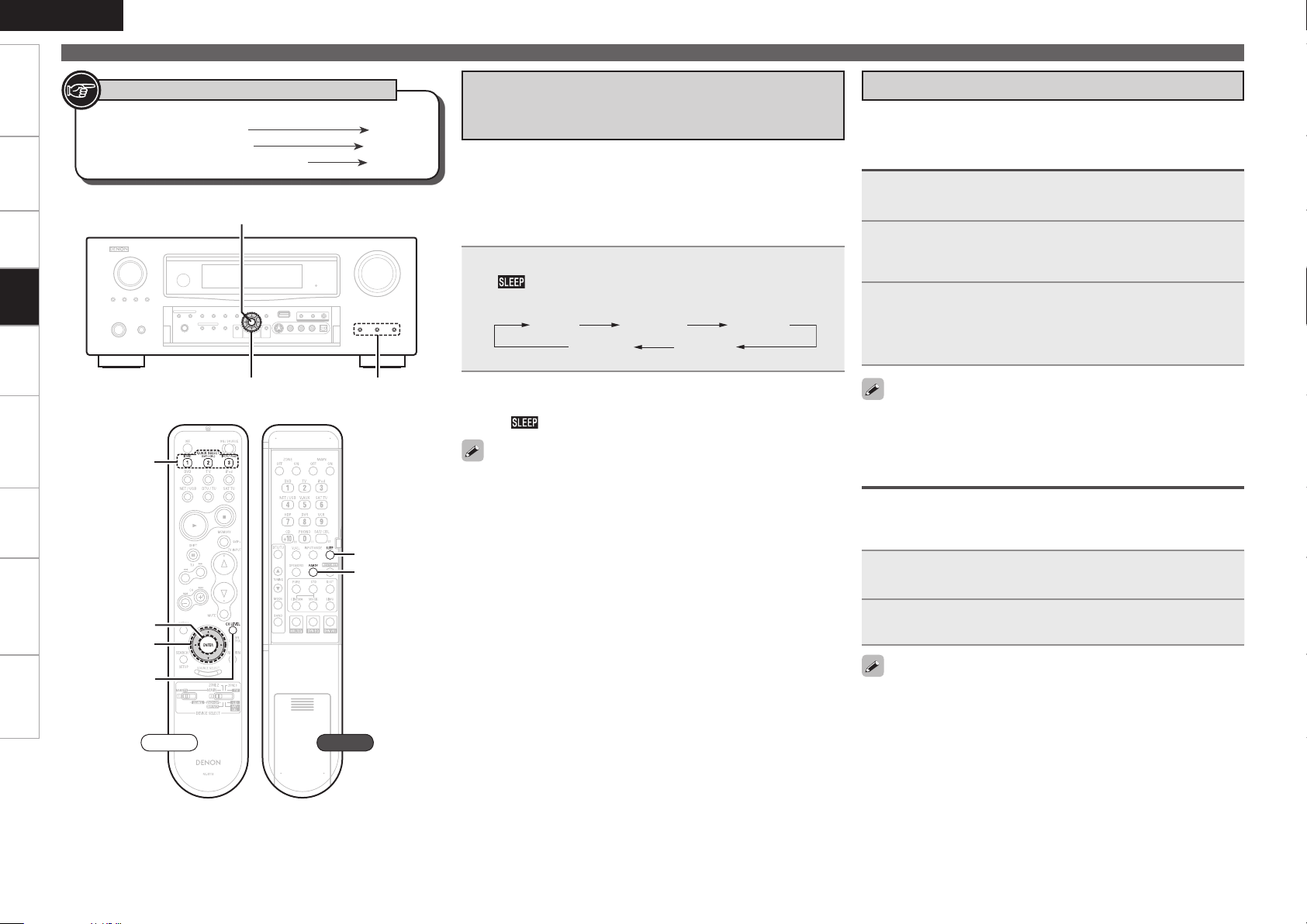
ENGLISH
OFF 120 min 90 min
60 min30 min
uio p
QUICK SELECT
ENTER
QUICK SELECT
uiop
ENTER
[CHANNEL
LEVEL]
[PARTY]
[SLEEP]
Getting Started Connections Settings Remote ControlMulti-zone Information Troubleshooting Specifications
Convenient Functions
Symbols used to indicate buttons in this manual
Button located on both the main unit
and the remote control unit
Button only on the main unit
Button only on the remote control unit
Playback
BUTTON
<BUTTON>
[BUTTON]
Setting the Power to Standby After a
Certain Amount of Time
(Sleep Timer Function)
With this function, you can set the AVR-3310 so that the power is
automatically switched to standby after the set amount of time has
passed.
This is convenient for playing sources while going to sleep.
When the sleep timer turns the power off in the MAIN ZONE, the
power also turns off in the ZONE2 and ZONE3.
Press [SLEEP] and display the time you want to set.
The “ ” indicator on the display lights.
The time switches as shown below each time [SLEEP] is pressed.•
Adjust the Volume of the Speakers
You can adjust the channel level either according to the playback
sources or to suit your taste, as described below.
Adjust the Volume of the Different Speakers
Press [CHANNEL LEVEL].
1
Use ui to select the speaker.
2
The speaker that can be set switches each time one of the
buttons is pressed.
Use o p to adjust the volume.
3
In the case of a subwoofer, press o when it is at “–12 dB” will
b
change the setting to “OFF”.
To cancel the sleep timer
n
Press [SLEEP] to set “OFF”.
The “ ” indicator on the display turns off.
The sleep timer setting is canceled if the AVR-3310’s power is set to
standby or turned off.
When a headphone jack is inserted, the headphone channel level can
be adjusted.
Adjusting the Volume of Groups of Speakers
(Fader Function)
This function lets you adjust (fade) the sound from all the front (Front
speaker / Front height speaker / Center speaker) or rear (Surround
speaker / Surround back speaker) speakers at once.
Front Rear
Use i to select “Fader”, then select the item to be
1
adjusting using o or p.
Use o p to adjust the volume of the speakers.
2
(o : front, p: rear)
The fader function does not affect the subwoofer.
•
The fader can be adjusted until the volume of the speaker adjusted
•
to the lowest value is –12 dB.
Page 81
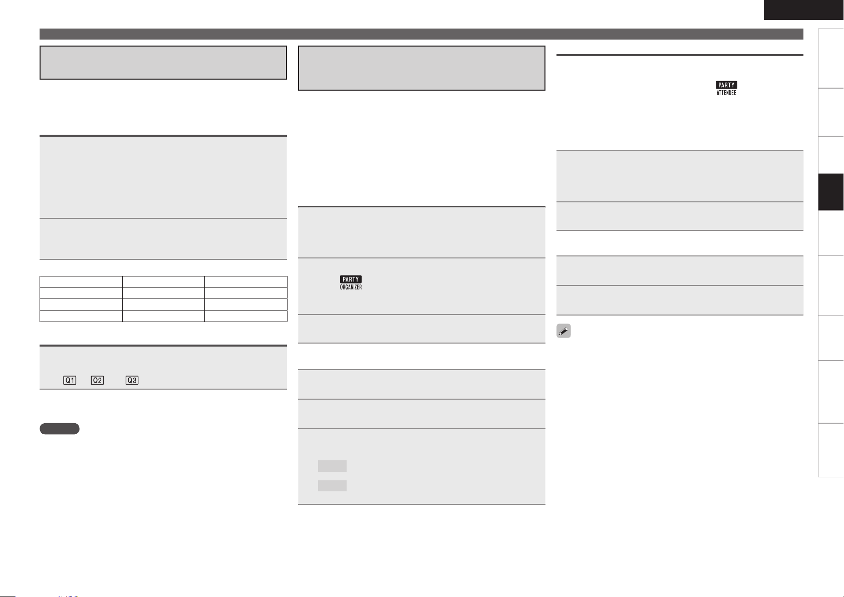
Saving Frequently Used Settings
(Quick Select Function)
All of the settings in step 1 can be memorized together. By memorizing
frequently used settings, you can quickly access and enjoy a playback
environment that is consistently the same.
Saving the Settings
Set the items below to the settings you want to save.
1
q Input Source (vpage 26)
w Volume Level (vpage 62)
e Surround Mode (vpage 64)
r Audyssey Setting (MultEQ®, Dynamic EQ™, Dynamic
Volume™) (vpage 69, 70)
t Video Select (vpage 46)
Press and hold the desired QUICK SELECT until
2
“Memory” appears on the display.
The current settings will be memorized.
GQuick Select DefaultsH
Input Source Volume
Quick Select 1 DVD –40dB
Quick Select 2 SAT/CBL –40dB
Quick Select 3 VCR –40dB
Calling the Settings Out
Press QUICK SELECT at which the settings you want to
call out are saved.
The “ ”, “ ” or “ ” indicator lights on the display.
Naming Quick Select settings
n
See “Quick Select Name” (vpage 41).
NOTE
Input sources stored with the quick select function cannot be selected
if they have been deleted at “Source Delete” (vpage 40). In this
case, store them again.
Playing the Same Network Audio
on Different Devices Connected in a
Network (Party Mode Function)
The same network audio (Internet Radio, Media Server or iPod
DIRECT) can be played on multiple DENON products equipped with
the Party Mode function and connected in a network.
The party mode consists of one organizer and up to four attendees.
When one unit starts the party mode as the organizer, up to four
devices on which the party mode function is activated automatically
participate in the party as attendees. “Party Mode Function” (vpage
38) must be set to “ON” ahead of time in order to use the party mode
function.
Starting the Party Mode as the Organizer
Press [PARTY] to become the organizer.
1
“Enter Party Mode?” is displayed.
An error message is displayed when you are not connected to a
b
network.
Press o p to select “Yes”, then press ENTER.
2
The “ ” indicator on the display lights. The input source
automatically switches to “NET/USB” and the attendees are
automatically selected.
Play the desired track.
3
To Cancel the Party Moden
While in the party mode, press [PARTY].
1
“Exit Party Mode?” is displayed on the GUI screen.
Press o p to select “Yes”, then press ENTER.
2
“Power off Attendees component?” is displayed.
Press o p to select “Yes” or “No”, then press
3
ENTER.
: The power of the attendees is turned off and the party
Yes
mode is canceled.
: The party mode is canceled without turning off the
No
power of the attendees.
ENGLISH
Convenient Functions
Participating in the Party Mode as an Attendee
When the organizer starts the party mode, up to four attendees are
•
selected automatically. No operation is required.
When a device becomes an attendee, “ ” appears on the
•
display. The input source automatically switches to “NET/USB” and
the same network audio as on the organizer is played.
If there are fewer than four attendees, a device can join the party
•
mode after it has started. To participate in the party mode, perform
the operation described below.
Press [PARTY].
1
“Enter Party Mode?” is displayed.
An error message is displayed when you are not connected to a
b
network.
Press o p to select “Yes”, then press ENTER.
2
To Cancel the Party Moden
While in the party mode, press [PARTY].
1
“Exit Party Mode?” is displayed on the GUI screen.
Press o p to select “Yes”, then press ENTER.
2
In this case, the other devices remain in the party mode.
“Napster” and “USB” are not available in the Party Mode.
There can only be one organizer in the network. To form a new party
mode, first cancel the current party mode.
Getting Started Connections Settings Remote ControlMulti-zone Information Troubleshooting Specifications
Playback
Page 82
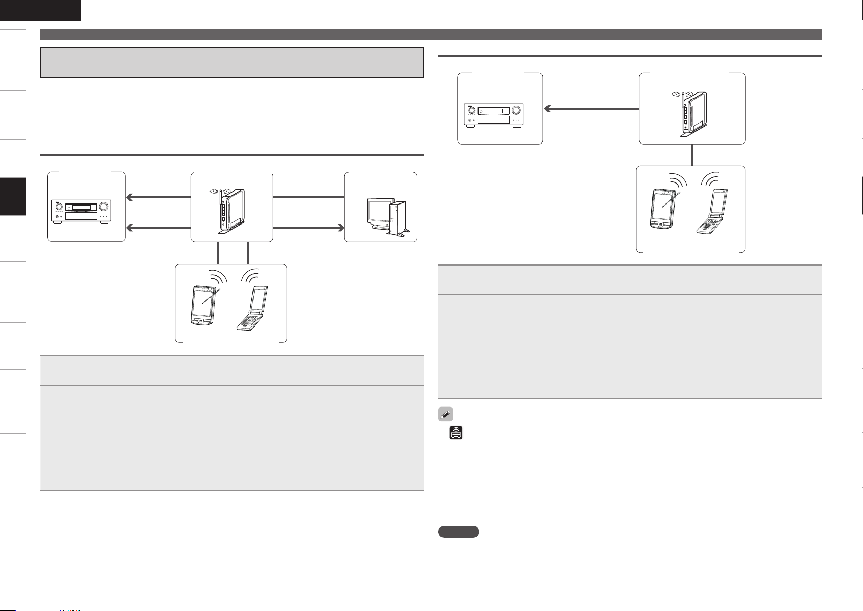
ENGLISH
Getting Started Connections Settings Remote ControlMulti-zone Information Troubleshooting Specifications
Convenient Functions
Operating a Wireless LAN-Compatible Mobile Terminal to Play
Music and Still Pictures
Perform this procedure using a wireless LAN-compatible mobile terminal conforming to the DLNA (Digital
•
Living Network Alliance) standard.
This function allows you to play contents located on a computer (music server) or mobile terminal device
•
connected in a network by operating a mobile terminal device in the same network.
There are two types of operations on the mobile terminal device.
•
Playing Contents on a Computer (Media Server)
Playback
AVR-3310
Wireless LANcompatible router
Playing Contents on a Mobile Terminal Device
AVR-3310
e Playback starts.
r Operation.
Computer
(Media server)
StreamingStreaming
Wireless LANcompatible router
e Playback starts.
r Operation.
Mobile terminal device
q Select a content
w Select a player
From the mobile terminal device, browse the media server in the same network and
1
choose the contents you want to play.
From the mobile terminal device, select the AVR-3310 among the products in the
2
network.
Playback of the contents selected in step 1 begins.
b
When selecting the AVR-3310 from the mobile terminal device, the name of the AVR-3310 is displayed
at “Friendly Name” (vpage 38 “Friendly Name Edit”).
The following operations are possible from the mobile terminal device:
b
File operations (play, stop, pause, track search)
•
Play mode settings (repeat/random)
•
Volume adjustment
•
q Select a content
Mobile terminal device
w Select a player
Select the contents you want to play from among the mobile terminal devices.
1
From the mobile terminal device, select the AVR-3310 among the products in the
2
network.
Playback of the contents selected in step 1 begins.
When selecting the AVR-3310 from the mobile terminal device, the name of the AVR-3310 is displayed
b
at “Friendly Name” (vpage 38 “Friendly Name Edit”).
The following operations are possible from the mobile terminal device:
b
File operations (play, stop, pause, track search)
•
Play mode settings (repeat/random)
•
Volume adjustment
•
“ ” is displayed on the GUI screen while the mobile terminal device is being operated.
•
For the various settings and operating procedures, see the operating instructions of the mobile terminal
•
devices being used.
When selecting the AVR-3310 from the mobile terminal device, the name of the AVR-3310 is displayed
•
at “Friendly Name”. “Friendly Name” can be edited at “Friendly Name Edit” (vpage 38) as desired so
that it is easily distinguishable from other devices.
When playback is started from the mobile terminal device, the AVR-3310’s input source automatically
•
switches to “NET/USB”. Also, when the “Network Standby” setting (vpage 38) is set to “ON”, the
power automatically turns on.
NOTE
When operations related to browsing or playback (play, stop, pause, track search) are performed on the
AVR-3310 while operating the mobile terminal device, the connection to the network is disconnected.
The network connection is also disconnected when the party mode is started.
Page 83
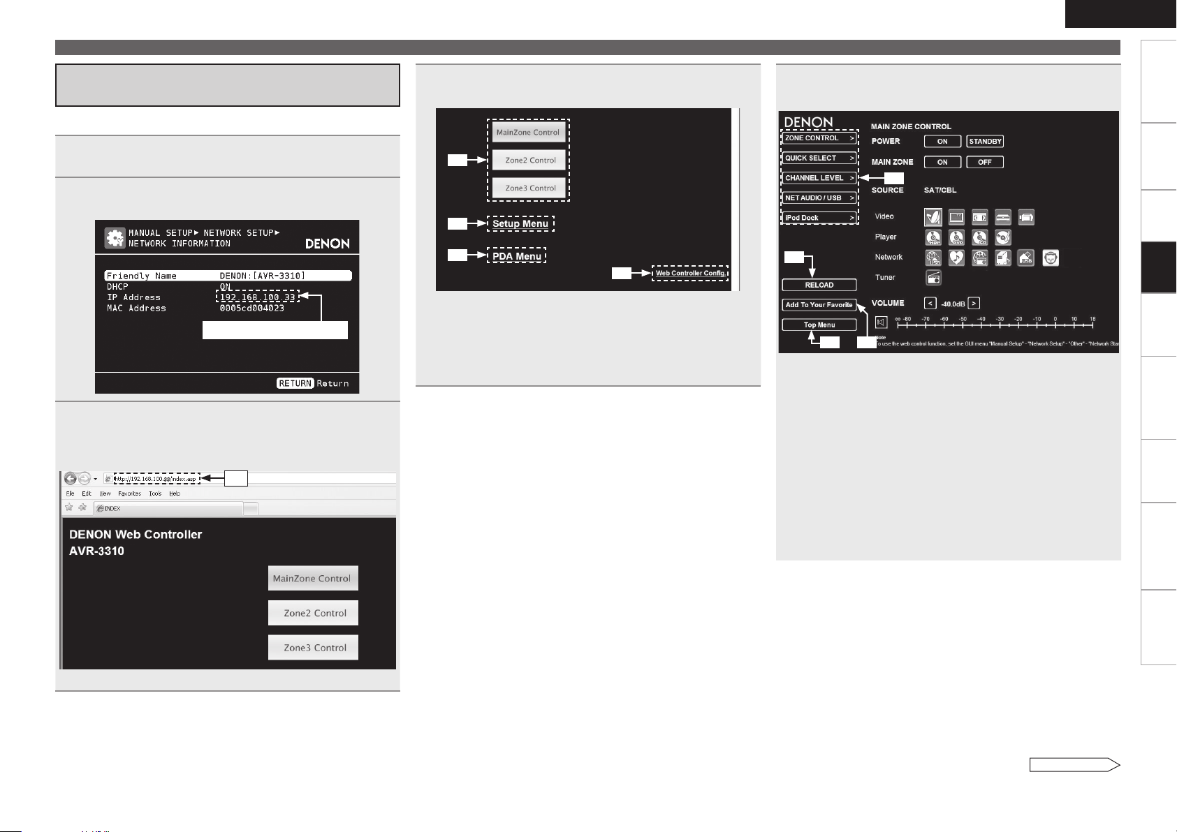
ENGLISH
Convenient Functions
Getting Started Connections Settings Remote ControlMulti-zone Information Troubleshooting Specifications
Operating the AVR-3310 with a Browser
(Web Control Function)
You can operate the AVR-3310 using a browser.
Switch “ON” the “Network Standby” setting
1
(vpage 38).
Check the AVR-3310’s IP address with “Network
2
Information” (vpage 39).
Checking the IP address.
Enter the AVR-3310 IP address in browser’s address
3
box.
For example, if the IP address of AVR-3310 is “192.168.100.33”,
enter “http://192.168.100.33”.
z1
When the top menu is displayed, click on the menu
4
you want to operate.
z2
z3
z5
z4
z2: Click when you operate each zone (vGExample 1H)
z3: Click when you operate the setup menu (vGExample 2H)
z4: Click to change the Web control screen setting. (vGExample
3H)
z5: Click when you operate a small screen such as a PDA screen,
etc. (vGExample 4H)
Operate.
5
z7
z8z6z9
z6: Click to perform each operation.
Changes to each operation screen (vGExample 5H)
z7: Click when you update to the latest information.
Normally, there is a change to the latest information each time
you operate. When operated from the main unit, click because
the screen is not updated.
z8: Click to return to the top menu.
Displayed when setting “Top Menu Link Setup” to “ON” in
GExample 3H
z9: Click to add a setting to the “Favorites” in your browser.
We recommend registering the setting screens for the different
zones in the browser’s favorites so as not to accidentally
perform menu operations for zones you do not intend to
operate.
GExample 1H Main zone control screen
Playback
z1: Entering the IP address.
See overleaf
Page 84
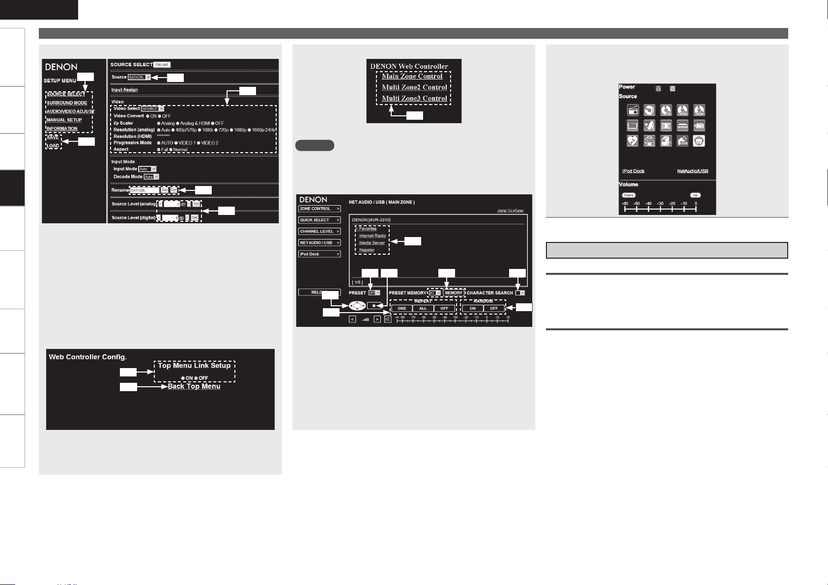
ENGLISH
Getting Started Connections Settings Remote ControlMulti-zone Information Troubleshooting Specifications
Convenient Functions
GExample 2H Setup menu screen
z10
z11
Playback
z10: Click the menu from which you want to make settings.
The display on the right becomes each setting screen.
z11: Click “SAVE” when you want to save settings, and click
“LOAD” when you want to call settings.
Becomes each operation screen.
z12: Click “v” and select from the displayed items.
z13: Click to determine a setting.
z14: After entering characters, click “Set” to set, or click “Def” to
return to initial setting.
z15: Enter figures or click “<” or “>” to make the setting, and then
click “Set”.
GExample 3H Web configuration screen
z16
z17
z16: Click “ON” when performing Top Menu Link Setup.
When set up, return to the top menu from each operation
screen. (Default setting : “OFF”)
z17: Click to return to the top menu.
z12
z13
z18: Select to operate each zone.
NOTE
You cannot change setup menu operations and zone name on the
PDA menu screen.
z14
z15
z24
z25
z19: Click the menu from which you want to play.
z20: Click “v” to select the preset channel you want to play.
z21: Click to stop play.
z22: When registering presets, click “v” to select the channel you
want to register, and then click “MEMORY”.
z23: When searching using an acronym, click “v” and select from
the displayed characters.
z24: Click when selecting menu.
z25: Click to repeat play.
z26: Click to random play.
GExample 4H PDA menu screen
z18
GExample 5H Net Audio operating screen
z19
z22 z23z20 z21
GExample 6H Dedicated iPod Touch screen
When accessed from the iPod Touch browser, an optimized
b
operation screen is displayed.
Various Memory Functions
Personal Memory Plus Function
This function sets the settings (input mode, surround mode, MultEQ,
Dynamic EQ, Dynamic Volume, audio delay etc.) last selected for the
individual input sources.
z26
Last Function Memory
This stores the settings as they were directly before the standby
mode was set.
When the power is turned back on, the settings are restored to as
they were directly before the standby mode was set.
0
Page 85
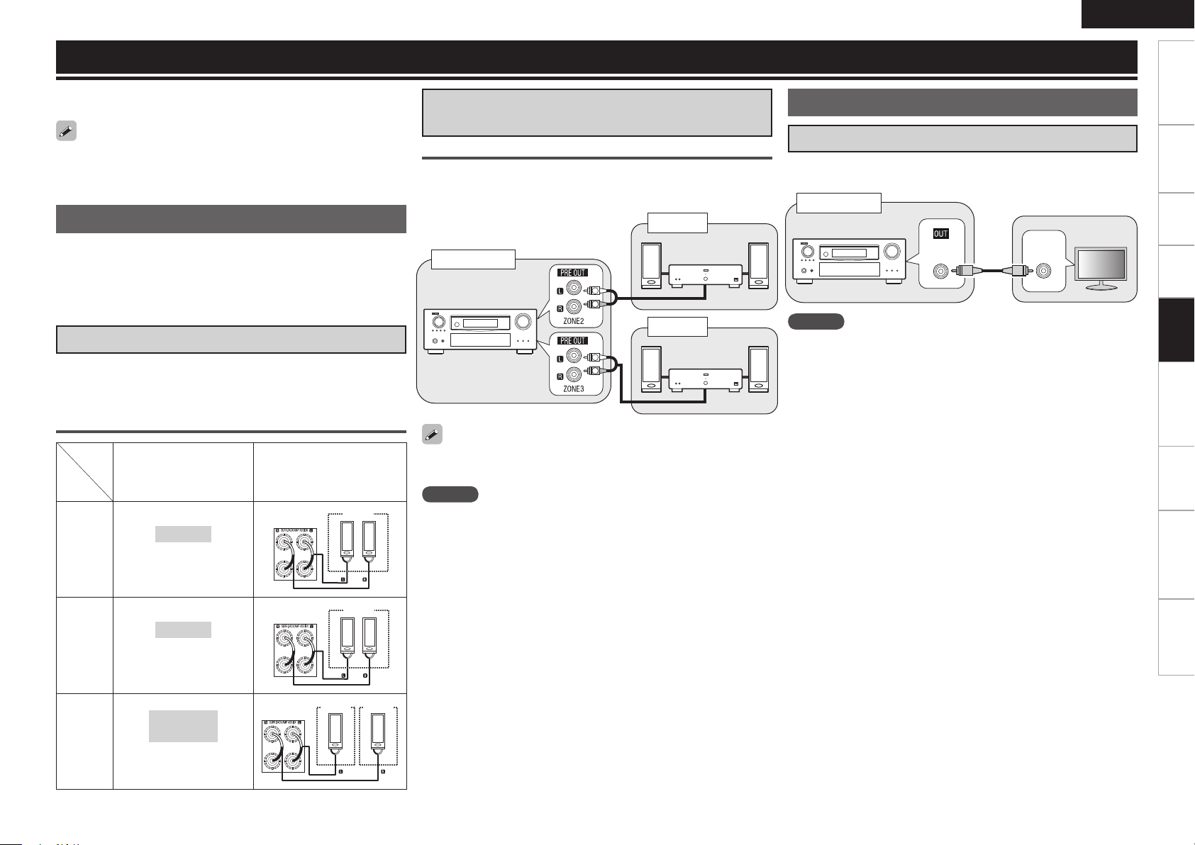
Playing in ZONE2/ZONE3 (Multi-zone Function)
w q w q
ZONE2
w q w q
ZONE3
ZONE2
ZONE3
w q w q
"69*/
"69*/
R
L
R
L
7*%&0
*/
7*%&0
;0/&
ENGLISH
Getting Started Connections Settings Playback Remote Control Information Troubleshooting Specifications
This function allows you to play sound in rooms other than the main
zone where multi-channel sound is played.
The source selected for ZONE2 is also output from the recording
output connectors.
Audio Output
There are two methods to do this, as described below. Choose one
of the methods.
q Zone playback by speaker output
w Zone playback by audio output (PRE OUT)
Use an external amplifier.
q Zone Playback by Speaker Output
The ZONE2 and ZONE3 audio signals are output from the AVR-3310’s
SURR BACK/AMP ASSIGN speaker terminals using the amplifier
assignment function.
Connecting and Setting the Speakers
Amp Assign mode
ZONE2
ZONE3
setting (vpage 33) and
the audio signals that
are output
ZONE2
Output signal :
Stereo (L / R)
ZONE3
Output signal :
Stereo (L / R)
Connecting the speakers
w Zone Playback by Audio Output
(PRE OUT)
Audio Connections (ZONE2, ZONE3)
The audio signals of the AVR-3310’s ZONE2 and ZONE3 audio output
terminals are output to the ZONE2 and ZONE3 amplifiers and played
on these amplifiers.
ZONE2
MAIN ZONE
AVR-3310
ZONE3
Also be sure to read the operating instructions of the connected
devices.
NOTE
We recommend using high quality pin-plug cables for audio
•
connections in order to prevent noise.
When the input source to which the digital input connectors
•
(OPTICAL/COAXIAL) are assigned is selected in ZONE2 or ZONE3,
playback is only possible if the digital signal being input is in PCM
(2-channel) format.
It is not possible to play the digital audio signals input from the HDMI
•
terminals in ZONE2 and ZONE3.
When certain digital signals are being input, noise may be output
•
from the ZONE2 and ZONE3 audio output connectors.
Video Output
Video Connection
The video signals of the AVR-3310’s ZONE2 video output terminal are
played by the ZONE2 TV.
MAIN ZONE
AVR-3310
Multi-zone
NOTE
It is not possible to output video signals input to the HDMI or
component terminals to ZONE2.
ZONE2
and
ZONE3
ZONE2/3-
MONO
Output signal :
Monaural
Page 86
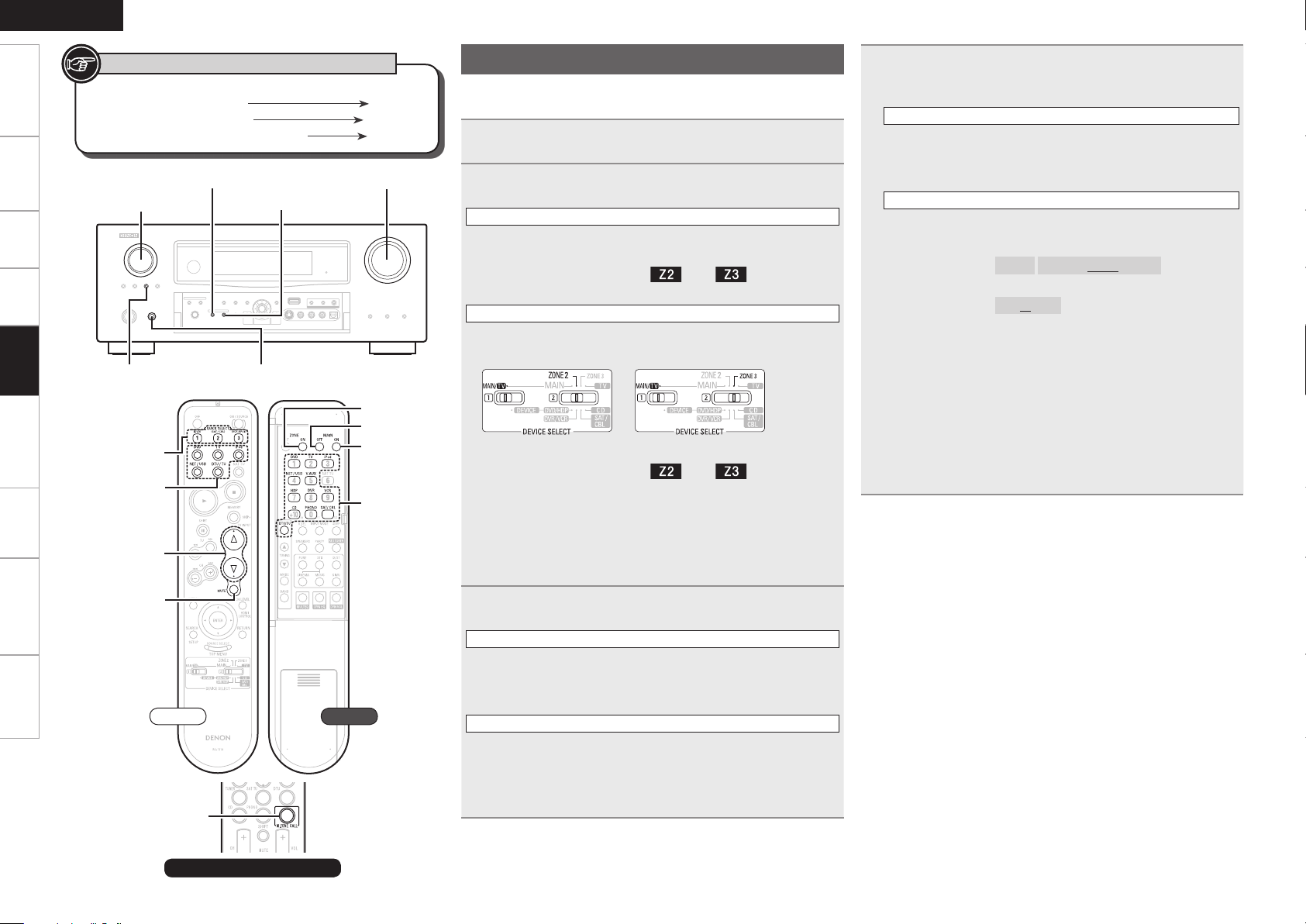
ENGLISH
<ZONE2/3 / REC SELECT>
<POWER>
<ZONE2 ON/OFF>
<MASTER VOLUME>
<ZONE3 ON/OFF>
<SOURCE SELECT>
[QUICK SELECT]
[VOLUME]
[MUTE]
[INPUT
SOURCE
SELECT]
[MAIN OFF]
[ZONE ON]
[MAIN ON]
[INPUT
SOURCE
SELECT]
[M.ZONE CALL]
Getting Started Connections Settings Playback Remote Control Information Troubleshooting Specifications
Button located on both the main unit
and the remote control unit
Button only on the main unit
Button only on the remote control unit
Multi-zone
Symbols used to indicate buttons in this manual
BUTTON
<BUTTON>
[BUTTON]
Front Rear
Playback
The operating procedure is the same for “q Zone Playback by Speaker
Output” and “w Zone Playback by Audio Output (PRE OUT)”.
Press <POWER>.
1
Turn on the zone power.
2
Operation on the main unit
Press <ZONE2 ON/OFF> or <ZONE3 ON/OFF> for the
zone to be operated.
When the power turns on, the “ ” or “ ” indicator lights
on the display.
Operation on the remote control unit
q Set the main remote control unit’s [DEVICE SELECT]
shown on below.
w Press [ZONE ON].
When the power turns on, the “ ” or “ ” indicator lights
on the display.
Also press [INPUT SOURCE SELECT] or [QUICK SELECT] when in
b
standby mode, the power turns on.
When using ZONE2 or ZONE3, it is possible to turn the power for
b
the MAIN ZONE only on or off by pressing [MAIN ON] or [MAIN
OFF].
Select the input source.
3
Operation on the main unit
q Press <ZONE2/3/ REC SELECT> and select the zone to
be adjusted.
w Turn <SOURCE SELECT> to choose the input source.
Operation on the remote control unit
In the zone mode you want to operate, press [INPUT
SOURCE SELECT].
The same input source as in the main zone can be selected easily
b
by pressing the [M.ZONE CALL] on the sub remote control unit.
Adjust the item below.
4
Adjust the Volume
n
Operation on the main unit
q Press <ZONE2/3/ REC SELECT> and select the zone
to be adjusted.
w Turn <MASTER VOLUME> to adjust.
Operation on the remote control unit
In the zone mode whose volume you want to adjust,
press [VOLUME].
GAdjustable rangeH
(When the “Volume Display” setting is “Relative”)
GAdjustable rangeH
(When the “Volume Display” setting is “Absolute”)
b
Upon purchase, “Volume Limit” is set to “-10dB (71)”.
Turning off the Sound Temporarily (MUTE)
n
In the zone mode for which you want to mute the
sound, press [MUTE].
The sound is reduced to the level set at menu “Mute Level”
(vpage 40).
To cancel, either adjust the volume or press [MUTE] again.
b
The setting is canceled when the zone’s power is turned off.
b
– – – –80dB ~ –40dB ~ 18dB
0 ~ 41 ~ 99
Sub remote control unit
Page 87
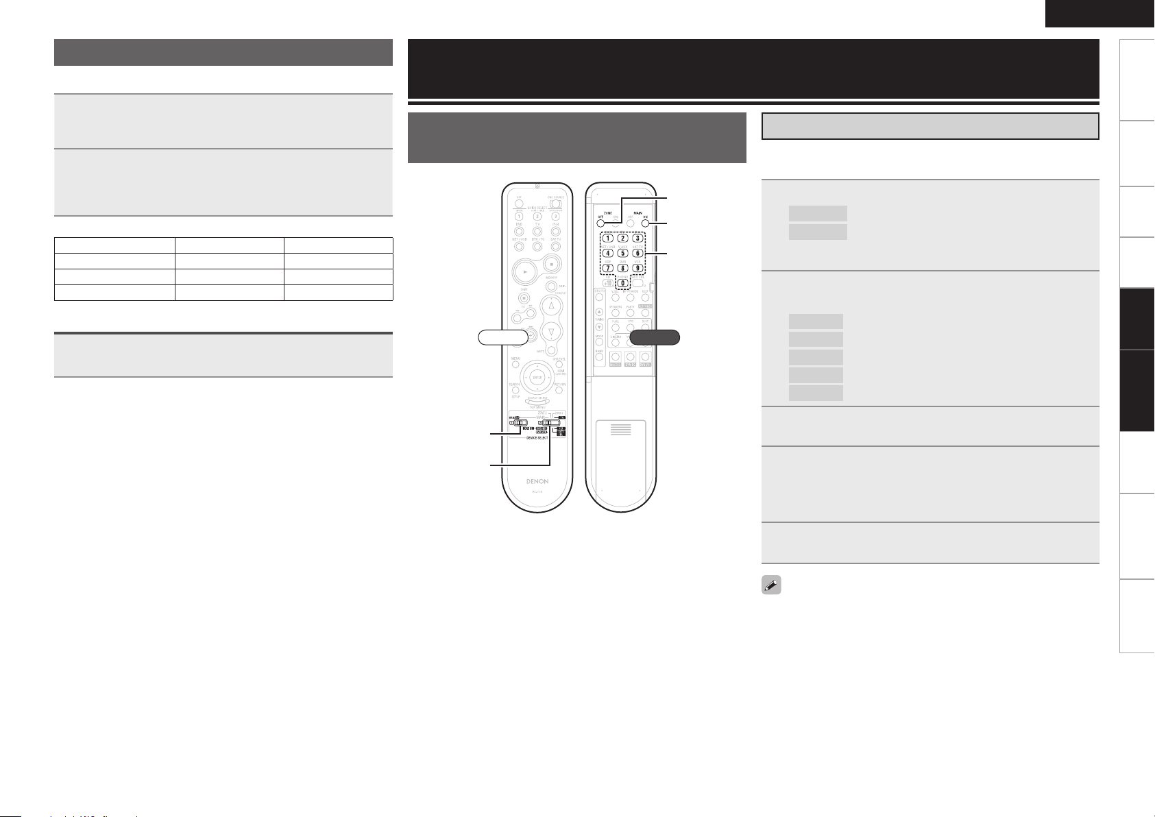
Quick Select Function
[DEVICE
SELECT 1]
[DEVICE
SELECT 2]
[MAIN ON]
[ZONE OFF]
[0 ~ 9]
It is also possible to save three settings for multi-zone.
Set the items below to the settings you want to save.
1
q Input Source (vpage 82)
w Volume Level (vpage 82)
In the zone mode for which you want to operate,
2
press and hold the desired [QUICK SELECT] until
“Memory” appears on the display.
The current settings will be memorized.
GQuick Select DefaultsH
Input Source Volume
Z2/Z3 Quick Select 1 DVD –40dB
Z2/Z3 Quick Select 2 SAT/CBL –40dB
Z2/Z3 Quick Select 3 VCR –40dB
Calling the Settings Out
Press [QUICK SELECT] at which the settings you want to
call out are saved.
Naming Quick Select settings
n
See “Quick Select Name” (vpage 41).
Operating the Connected Devices by Remote Control
Unit
Operating the Main Remote
Control Unit
Front Rear
Registering Preset Codes
DENON and other makes of components can be operated by setting
the preset memory.
Switch [DEVICE SELECT 1].
1
MAIN/TV
DEVICE
Set [DEVICE SELECT 2] to the component to be
2
registered.
DVD/HDP
DVR/VCR
SAT/CBL
Press [ZONE OFF] and [MAIN ON] at the same time.
3
The indicator starts flashing.
: To register a TV
: To operate a Blu-ray disc player, DVD player, Digital
video recorder, video deck, satellite receiver,
cable TV or CD player
: TV
TV
: DVD player or Blu-ray disc player
: Digital video recorder or video deck
: Satellite receiver or cable TV
: CD player
CD
ENGLISH
Getting Started Connections Settings Playback Information Troubleshooting Specifications
Multi-zone Remote Control
Press [0 ~ 9] and input the 3-digit number of the
4
brand of the component to be preset. The numbers
are shown in the Preset Code Table (vEnd of this
manual).
To store the codes of another component in the
5
memory, repeat steps 1 to 4.
Some manufacturers use more than one type of remote control code.
•
Refer to the included list of preset codes to change the number and
verify correct operation.
VDP (Video Disc Player) can be preset when [DEVICE SELECT 2] is
•
set to “DVD/HDP”.
The preset memory can be set for one component only among the
•
following: TV, DVD/HDP, DVR/VCR, SAT/CABLE and CD.
Depending on the model and year of manufacture of your equipment,
•
some buttons may not operate.
Page 88
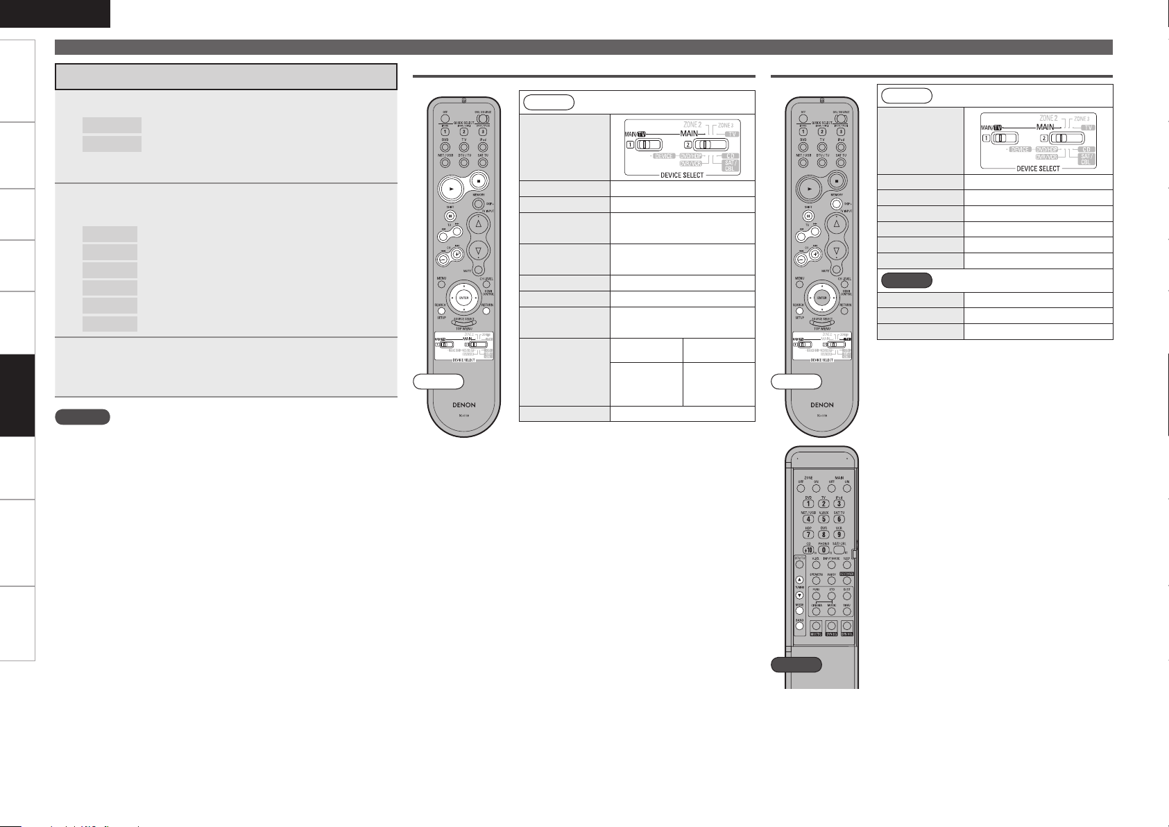
ENGLISH
Getting Started Connections Settings Playback Multi-zone Information Troubleshooting Specifications
Operating the Main Remote Control Unit
Operating Components
Switch [DEVICE SELECT 1].
1
MAIN/TV
DEVICE
Set [DEVICE SELECT 2] to the component you want
2
to operate.
MAIN
DVD/HDP
DVR/VCR
SAT/CBL
Remote Control
Operate the component.
3
For details, refer to the component’s operating instructions.b
NOTE
Depending on the model and year of manufacture, this function cannot
be used for some models, even if they are of makes listed in the list
of preset codes.
: To operate the TV, iPod, TUNER or NET/USB
: To operate a Blu-ray disc player, DVD player,
Digital video recorder, video deck, satellite
receiver, cable TV or CD player
: iPod, TUNER or NET/USB
: TV
TV
: DVD player or Blu-ray disc player
: Digital video recorder or video deck
: Satellite receiver or cable TV
: CD player
CD
iPod
Front
Front
DEVICE SELECT
Signal
1
transmission
2
indicator
6 7
8 9
uio p
ENTER Enter
3
SEARCH
RETURN Return
(fast-reverse / fast-forward)
Press and
hold
Browse/Remote
mode switching
Play / Pause
Stop
Manual search
Auto search
(cue)
Cursor
Pause
Page search
switching
Once
mode
TUNER (FM/AM)
Front
Front
DEVICE SELECT
SHIFT Preset channel selection
MEMORY Preset memory registration
TU Tuning +/–
CH + – Preset channel selection
SEARCH RDS search
uio p
Cursor
Rear
TUNING df
MODE Switch search modes
BAND AM/FM Switching
Tuning +/–
Rear
Page 89
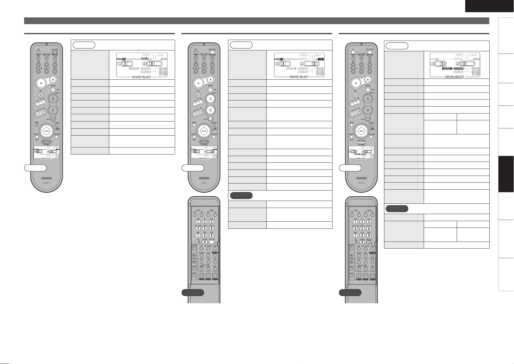
NET/USB
TV
Operating the Main Remote Control Unit
Blu-ray disc Player / DVD Player
ENGLISH
Getting Started Connections Settings Playback Multi-zone Information Troubleshooting Specifications
Front
Front
DEVICE SELECT
1
2
SHIFT Preset channel selection
MEMORY Preset memory registration
6 7
CH + – Preset channel selection
uio p
ENTER Enter
SEARCH
RETURN Return
Play/Pause
Stop
Switching picture
Cursor
Page Search /
Character Search
Front
Front
DEVICE SELECT
ON/SOURCE Power on / Standby
1 Play
3 Pause
2 Stop
6 7
CH + –
TV INPUT Switching the input
VOLUME df
MUTE TV mute
MENU Calling out the menus
uio p
ENTER Enter setting
SETUP Setup
RETURN Return
(fast-reverse / fast-forward)
Switch channels (+, –)
z
z
z
Manual search
d : TV Volume (+)
f : TV Volume (–)
Cursor operation
z
z
Rear
1 ~ 12 Channels
Defau
lt setting
(Preset code)
Special Remarks
z
: When the punch through function (vpage
87) is set, this functions as the button for the
device for which punch through is set.
HITACHI
(014)
q
Front
Front
DEVICE SELECT
POWER OFF Power off
ON/SOURCE Power on or Power on / Standby
1
2
3
BD Player DVD Player
SKIP +
6 7
8 9
MENU Calling out the menus
uio p
ENTER Enter setting
SETUP Setup
RETURN Return
SOURCE SELECT /
TOP MENU
(fast-reverse / fast-forward)
Calling out the top menus
Play
Stop
Pause
– Disc skip
Manual search
Auto search (cue)
Cursor operation
Rear
0 ~ 9, +10 Number input / Track selection
Defau
lt setting
(Preset code)
Special Remarks
* : The initial setting of Preset code is 111 (DVD Play-
er).
BD Player DVD Player
q, w
DENON
*
(111)
DENON
(121)
Remote Control
Rear
【Special Remarks】
q Only one device can be set in the preset memory for each mode.
When a new preset code is registered, the existing code is automatically erased.
w For some brands, the DVD remote control buttons may have different function names. Check beforehand.
Rear
Page 90

ENGLISH
Getting Started Connections Settings Playback Multi-zone Information Troubleshooting Specifications
Operating the Main Remote Control Unit
Digital Video Recorder (DVR) / Video Deck (VCR)
Satellite receiver/Cable TV
CD Player
Front
DEVICE SELECT
ON/SOURCE Power on / Standby
1
2
3
6 7
CH + –
MENU Calling out the menus
uio p
ENTER Enter setting
Remote Control
Front
SETUP Setup
RETURN Return
Rear
0 ~ 9, +10
Defau
lt setting
(Preset code)
Special Remarks
(fast-reverse / fast-forward)
Play
Stop
Pause
Manual search
Switch
channels (+, –)
Cursor operation
C
hannel
HITACHI
(008)
q
Front
s
Front
DEVICE SELECT
ON/SOURCE Power on / Standby
1 Play
3 Pause
2 Stop
6 7
CH + –
uio p
ENTER Enter setting
MENU
SETUP
RETURN Return
(fast-reverse / fast-forward)
Switch channels (+, –)
Calling out the menus
z
z
z
Manual search
Cursor operation
Setup
z
z
Rear
0 ~ 9, +10 Channels
Satellite
Defau
lt setting
(Preset code)
Special Remarks
z
: When the punch through function (vpage
87) is set, this functions as the button for the
device for which punch through is set.
Receiver
–
Cable TV
ABC
(009)
q
Front
Front
DEVICE SELECT
POWER OFF Power off
ON/SOURCE Power on or Power on / Standby
1
2
3
SKIP + Disc skip +
6 7
8 9
(fast-reverse / fast-forward)
Play
Stop
Pause
Manual search
Auto search (cue)
Rear
0 ~ 9, +10 Number input / Track selection
Defau
lt setting
(Preset code)
Special Remarks
DENON
(111)
q
Rear
【Special Remarks】
q Only one device can be set in the preset memory for each mode.
When a new preset code is registered, the existing code is automatically erased.
Rear
Rear
Page 91
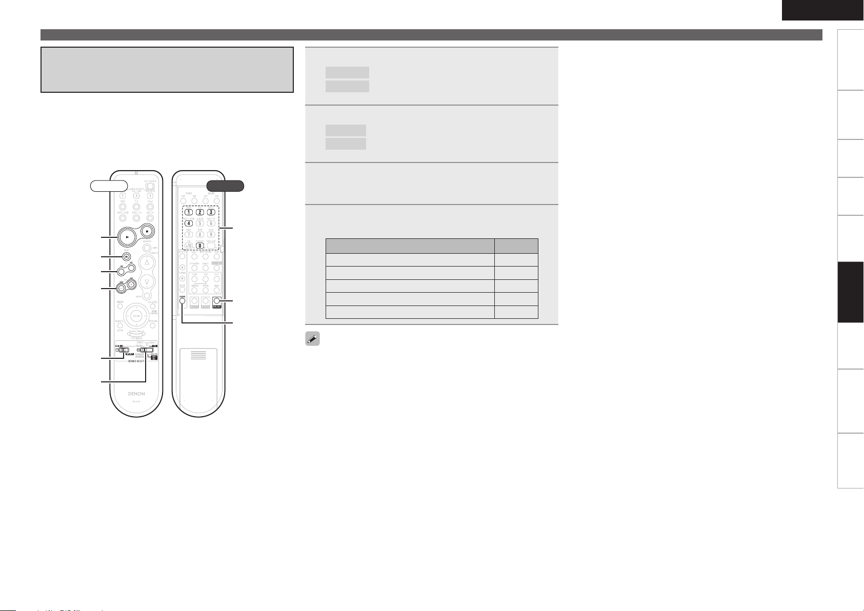
ENGLISH
[DEVICE
SELECT 1]
[DEVICE
SELECT 2]
[1], [2]
[3]
[6], [7]
[8], [9]
[BAND]
[DYNAMIC
VOLUME]
[0, 1 ~ 4]
Operating the Main Remote Control Unit
Getting Started Connections Settings Playback Multi-zone Information Troubleshooting Specifications
Assigning buttons that are Not Used to
Operate Other Devices
(Punch Through Function)
The Blu-ray disc Player/DVD player, Digital Video recorder, video deck,
or CD player can be operated as described below even when [DEVICE
SELECT 2] is set to the “SAT/CBL” or “TV” position.
• Play (1) • Stop (2) • Pause (3)
• fast-forward (7) • fast-reverse (6)
• Auto Search (8, 9)
Front Rear
Switch [DEVICE SELECT 1].
1
MAIN/TV
DEVICE
Switch [DEVICE SELECT 2].
2
SAT/CBL
Press [BAND] and [DYNAMIC VOLUME] at the same
3
time.
The indicator starts flashing.
Refer to the table below and input the number
4
corresponding to the device to be assigned.
iPod, TUNER, NET/USB
CD Player
Blu-ray disc Player / DVD Player
Digital Video Recorder, Video Deck
No setting
: Assigning TV buttons to operate other devices
: Assigning satellite receiver or cable TV buttons to
operate other devices
: Assigning TV buttons to operate other devices
TV
:
Assigning satellite receiver or cable TV buttons to
operate other devices
Device to be assigned Numbers
[1]
[2]
[3]
[4]
[0]
Remote Control
This is set to “No setting” upon purchase.
Page 92

ENGLISH
uio p
[USB]
[RANDOM]
[ALL MUSIC/
FAVORITES]
[MENU]
[M. ZONE CALL]
[ZONE OFF]
[ADVANCED
SETUP]
[ZONE SELECT]
[INPUT SOURCE SELECT]
[ZONE ON]
[VOLUME
+, –
]
[
MEMORY
]
[
ENTER
]
[
RETURN
]
[SEARCH]
[REPEAT]
[
8,9
],
[2], [
1/3
],
[TUNINGdf]
[
CHANNEL +, –
]
[
SHIFT
]
[
MUTE
]
Getting Started Connections Settings Playback Multi-zone Information Troubleshooting Specifications
Operating the Sub Remote
Control Unit
• The sub remote control unit is equipped with frequently used buttons,
so it can be used for simple remote control unit operations.
• The sub remote control unit can also be used for multi-zone, so you
can use it to control the AVR-3310 from other rooms.
• The operations listed below can be performed with the sub remote
control unit.
•
Switching the input source
•
Adjusting the volume
•
TUNER and iPod operations
•
NET/USB direct play
•
GUI menu operations
•
Zone power on/off
• It is not possible to operate devices other than the amplifier.
The AVR-3310 cannot be used in the ZONE4 mode.
Remote Control
Functions of Buttons by Component
Device operated TUNER (FM/AM) NET/USB iPod
Zone selection M Z2 Z3 M Z2 Z3 M Z2 Z3
ZONE SELECT Zone operation mode selection
ZONE OFF
ZONE ON
INPUT SOURCE SELECT Input source selection
CHANNEL + / – Preset channel selection –
SHIFT Preset channel memory block selection –
VOLUME + / –
MUTE
MENU Menu – Menu – Menu –
MEMORY Preset memory registration –
u i o p
ENTER – Enter
SEARCH RDS search
RETURN – Return
8 9,
TUNING d f
2
1/3
REPEAT – 1-track/All-track repeat play 1-track/All-track repeat play
RANDOM – 1-track random play 1-track/album shuffle play
USB
ALL MUSIC *
(Music server only)
FAVORITES *
b1: Affects the currently selected zone.
b2: The input source switches to “NET/USB” and the files on the USB memory device are played.
b3: The input source switches to “NET/USB” and the files in “All Music” on the music server are played.
b4: The input source switches to “NET/USB” and the files in “Favorites” are played.
*: Whether “All Music” or “Favorites” is selected depends on the “Direct Play” setting (vpage 49).
• Playback is possible in the mode selected at GUI menu “Direct Play”.
FAVORITES: Playback starts from the first track registered in the favorites.
ALL MUSIC: Playback starts from the first track registered in the “All Music” folder.
• When [USB] is pressed, playback starts from the first track on the USB memory device.
NOTE
When the music server is stopped or restarted, it may no longer be possible to play tracks stored in the favorites.
Tuning Track search
– Stop
– Play / Pause
DIRECT PLAY button
Power turned off (b1)
Power turned on (b1)
Adjustment of volume (b1)
Muting (b1)
Cursor
Page forward screen /
Character search
b
2
b
3
b
4
Page forward screen /
Browse/Remote mode switching
(press and hold)
Page 93

ENGLISH
Operating the Sub Remote Control Unit
Getting Started Connections Settings Playback Multi-zone Information Troubleshooting Specifications
Switching Zones
Use this procedure to select the zone to be operated by the sub
remote control unit.
Press [ZONE SELECT].
1
The currently selected multi-zone indicator lights.
While the multi-zone indicator is light, press [ZONE
2
SELECT] to select the zone to be operated.
The currently selected multi-zone indicator lights.
Switching the Multi-zone Input Source
to the Same Input Source as Used in the
MAIN ZONE
This function is convenient for example when you want to listen to the
same song as the one playing in the MAIN ZONE while in a different
zone.
Press [ZONE SELECT] and set to ZONE2 or ZONE3.
1
The currently selected multi-zone indicator lights.
Press [M.ZONE CALL] on the sub remote control unit.
2
The multi-zone input source switches to the MAIN ZONE’s
input source.
NOTE
This cannot be used for the MAIN ZONE or ZONE4.
•
When [M.ZONE CALL] is pressed while the multi-zone power is off,
•
the multi-zone power turns on and the input source switches to the
MAIN ZONE’s input source.
Setting the Zone for Which the Sub
Remote Control Unit is Used
(ZONE SELECT LOCK Mode)
We recommend always using the sub remote control unit for the
same room. When this is done, the unit can be set so that the zone
does not switch when buttons are operated.
Use the tip of a pen to press [ADVANCED SETUP].
All the multi-zone indicators light.
1
Select the multi-zone to be set.
The selected multi-zone indicator lights.
2
q To set to “MAIN ZONE” : Press [REPEAT].
w To set to “ZONE2” : Press [RANDOM].
e To set to “ZONE3” : Press [USB].
r To set to “ZONE4” : Press [ALL MUSIC/FAVORITES].
Use the tip of a pen to press [ADVANCED SETUP].
The multi-zone indicator turns off.
3
To Cancel
Use the tip of a pen to press [ADVANCED SETUP].
The currently selected multi-zone indicator lights.
1
Press [ZONE SELECT].
2
All the multi-zone indicators light.
Use the tip of a pen to press [ADVANCED SETUP].
The multi-zone indicator turns off.
3
Setting the Remote ID
When using multiple DENON AV receivers in the same room, make this
setting so that no AV receiver other than the desired one operates.
While pressing [MENU], press [ADVANCED SETUP]
1
with the tip of a pen.
The multi-zone indicator corresponding to the currently selected
remote ID flashes.
Select the remote ID to be set.
2
q To set to 1 : Press [REPEAT].
The “M” indicator flashes.
w To set to 2 : Press [RANDOM].
The “Z2” indicator flashes.
e To set to 3 : Press [USB].
The “Z3” indicator flashes.
r To set to 4 : Press [ALL MUSIC/FAVORITES].
The “Z4” indicator flashes.
While pressing [MENU], press [ADVANCED SETUP]
3
with the tip of a pen.
The multi-zone indicator turns off.
NOTE
When changing a setting, be sure to set the same remote ID as the
AVR-3310’s (vpage 42).
Resetting the Settings
While pressing [ZONE OFF], press [ADVANCED SETUP]
with the tip of a pen.
All the multi-zone indicators flash 4 times, then all the settings are
restored to their defaults.
Remote Control
Page 94

ENGLISH
Getting Started Connections Settings Playback Remote ControlMulti-zone Troubleshooting Specifications
Other Information
Explanation of Terms
The AVR-3310 is equipped with a digital signal processing circuit that
lets you play program sources in the surround mode to achieve the
same sense of presence as in a movie theater.
Dolby Surround
Dolby Digital
Dolby Digital is a multi-channel digital signal format developed by
Dolby Laboratories.
A total of 5.1-channels are played: 3 front channels (“FL” , “FR” and
“C”), 2 surround channels (“SL” and “SR”) and the “LFE” channel for
low frequencies.
Because of this, there is no crosstalk between channels and a realistic
sound field with a “three-dimensional” feeling (sense of distance,
movement and positioning) is achieved.
A real, overpowering sense of presence is achieved when playing
movie sources in AV rooms as well.
Dolby Digital Plus
Dolby Digital Plus is an improved Dolby Digital signal format that is
Information
compatible with up to 7.1-channels of discrete digital sound and also
improves sound quality thanks to extra data bit rate performance. It
is upwardly compatible with conventional Dolby Digital, so it offers
greater flexibility in response to the source signal and the conditions
of the playback equipment.
Dolby TrueHD
Dolby TrueHD is a high definition audio technology developed by Dolby
Laboratories, using lossless coding technology to faithfully reproduce
the sound of the studio master.
This format is compatible with a maximum sampling frequency of 96
kHz and up to 7.1-channels, so it is used for applications particularly
prioritizing sound quality.
Dolby Pro Logic g
Dolby Pro Logic g is a matrix decoding technology developed by Dolby
Laboratories.
Regular music such as that on CDs is encoded into 5-channels to
achieve an excellent surround effect.
The surround channel signals are converted into stereo and full band
signals (with a frequency response of 20 Hz to 20 kHz or greater) to
create a “three-dimensional” sound image offering a rich sense of
presence for all stereo sources.
0
Dolby Pro Logic gx
Dolby Pro Logic gx is a further improved version of the Dolby Pro
Logic g matrix decoding technology.
Audio signals recorded in 2-channels are decoded to achieve a natural
sound with up to 7.1-channels.
There are 3 modes: “Music” suited for playing music, “Cinema”
suited for playing movies, and “Game” which is optimized for playing
games.
Dolby Digital EX
Dolby Digital EX is a 6.1-channel surround format proposed by Dolby
Laboratories that allows users to enjoy in their homes the “DOLBY
DIGITAL SURROUND EX” audio format jointly developed by Dolby
Laboratories and Lucas Films.
The 6.1 channels of sound, including surround back channels, provide
improved sound positioning and expression of space.
Dolby Pro Logic IIz
Dolby Pro Logic gz introduces a new dimension to Home Entertainment
through the addition of a pair of front height channels. Compatible with
stereo, 5.1 and 7.1 content, Dolby Pro Logic gz provides enhanced
spaciousness, depth and dimension to movies, concert video and
video game playback while maintaining the full integrity of the source
mix.
Dolby Pro Logic gz identifies and decodes spatial cues that occur
naturally in all content, directing this information to the front height
channels, complementing the performance of left and right surround
sound speakers. Content that is encoded with Dolby Pro Logic
gz height channel information can be even more revealing, with
perceptually discrete height channel information bringing an exciting
new dimension to home entertainment.
Dolby Pro Logic gz, with front height channels is also an ideal alternative
for households that cannot support the placement of back surround
speakers of a typical 7.1 channel system but may have bookshelf
space available to support the addition of height speakers.
Manufactured under license from Dolby Laboratories. “Dolby”,
“Pro Logic” and the double-D symbol are trademarks of Dolby
Laboratories.
DTS Surround
DTS Digital Surround
DTS Digital Surround is the standard digital surround format of DTS,
Inc., compatible with a sampling frequency of 44.1 or 48 kHz and up
to 5.1-channels of digital discrete surround sound.
DTS-HD High Resolution Audio
DTS-HD High Resolution Audio is an improved version of the
conventional DTS, DTS-ES and DTS 96/24 signals formats, compatible
with sampling frequencies of 96 or 48 kHz and up to 7.1-channels
of discrete digital sound. High data bit rate performance provides
high quality sound. This format is fully compatible with conventional
products, including conventional DTS digital surround 5.1-channel
data.
DTS-HD Master Audio
DTS-HD Master Audio is DTS, Inc’s lossless audio format compatible
with up to 96 kHz/7.1-channels. The lossless audio coding technology
faithfully reproduces the sound of the studio master. It is fully
compatible with conventional products, including conventional DTS
digital surround 5.1-channel data.
DTS-ES™ Discrete 6.1
DTS-ES™ Discrete 6.1 is a 6.1-channel discrete digital audio format
adding a surround back (SB) channel to the DTS digital surround
sound.
Decoding of conventional 5.1-channel audio signals is also possible
according to the decoder.
DTS-ES™ Matrix 6.1
DTS-ES™ Matrix 6.1 is a 6.1-channel discrete digital audio format
inserting a surround back (SB) channel to the DTS digital surround
sound through matrix encoding. Decoding of conventional 5.1-channel
audio signals is also possible according to the decoder.
DTS NEO:6™ Surround
DTS NEO:6™ is a matrix decoding technology for achieving 6.1channel surround playback with 2-channel sources. It includes “DTS
NEO:6 Cinema” suited for playing movies and “DTS NEO:6 Music”
suited for playing music.
Page 95

DTS 96/24
DTS 96/24 is a digital audio format enabling high sound quality
playback in 5.1-channels with a sampling frequency of 96 kHz and 24
bit quantization on DVD-Video.
DTS Express
DTS Express is an audio format supporting low bit rates (max. 5.1channels, 24 to 256 kbps).
Manufactured under license under U.S. Patent #’s: 5,451,942;
5,956,674; 5,974,380; 5,978,762; 6,226,616; 6,487,535; 7,212,872;
7,333,929; 7,392,195; 7,272,567 & other U.S. and worldwide patents
issued & pending. DTS is a registered trademark and the DTS logos,
Symbol, DTS-HD and DTS-HD Master Audio are trademarks of DTS,
Inc. © 1996-2008 DTS, Inc. All Rights Reserved.
Audyssey
Audyssey MultEQ
Audyssey MultEQ is a room equalization solution that calibrates any
audio system so that it can achieve optimum performance for every
listener in a large listening area. Based on several room measurements,
MultEQ calculates an equalization solution that corrects for both
time and frequency response problems in the listening area and also
performs a fully automated surround system setup.
Audyssey Dynamic EQ™
Audyssey Dynamic EQ solves the problem of deteriorating sound
quality as volume is decreased by taking into account human perception
and room acoustics. Audyssey Dynamic EQ works in tandem with
Audyssey MultEQ to provide well-balanced sound for every listener
at any volume level.
Audyssey Dynamic Volume™
Audyssey Dynamic Volume solves the problem of large variations in
volume level between television programs, commercials, and between
the soft and loud passages of movies.
Audyssey Dynamic EQ is integrated into Dynamic Volume so that as
the playback volume is adjusted automatically, the perceived bass
response, tonal balance, surround impression, and dialog clarity
remain the same.
®
ENGLISH
Explanation of Terms
About Networks
Windows Media Player Ver.11
This is a media player distributed free of charge by Microsoft
Corporation.
It can be used to play playlists created with Windows Media Player
Ver. 11 as well as files in such formats as WMA, DRM WMA, MP3
and WAV.
vTuner
This is a free online contents server for Internet radio. Note that usage
fees are included in upgrade costs.
For inquiries about this service, visit the vTuner site below.
vTuner website: http://www.radiodenon.com
This product is protected by certain intellectual property rights of
Nothing Else Matters Software and BridgeCo. Use or distribution of
such technology outside of this product is prohibited without a license
from Nothing Else Matters Software and BridgeCo or an authorized
subsidiary.
DLNA
• DLNA and DLNA CERTIFIED are trademarks and/or service marks of
Digital Living Network Alliance.
• Some contents may not be compatible with other DLNA CERTIFIED™
products.
Getting Started Connections Settings Playback Remote ControlMulti-zone Troubleshooting Specifications
Information
Manufactured under license from Audyssey Laboratories. U.S.
and foreign patents pending. Audyssey MultEQ® is a registered
trademark of Audyssey Laboratories. Audyssey Dynamic EQ™ is a
trademark of Audyssey Laboratories. Audyssey Dynamic Volume™
is a trademark of Audyssey Laboratories.
AL24 Processing Plus
AL24 Processing for All Channels
DENON has further developed its proprietary AL24 Processing, an
analog waveform reproduction technology, to support the 192 kHz
sampling frequency. AL24 Processing Plus, thoroughly suppresses
quantization noise associated with D/A conversion of LPCM signals to
reproduce the low-level signals with optimum clarity that will bring out
all the delicate nuances of the music.
Equipped foe not only front left and right channels but also for the
surround left and right, center and subwoofer channels.
Windows Media DRM
A copyright-protected technology developed by Microsoft.
Content providers are using the digital rights management technology
for Windows Media contained in this device (WM-DRM) to protect
the integrity of their content (Secure Content) so that their intellectual
property, including copyright, in such content is not misappropriated.
This device uses WM-DRM software to play Secure Content (WMDRM Software). If the security of the WM-DRM Software in this device
has been compromised, owners of Secure Content (Secure Content
Owners) may request that Microsoft revoke the WM-DRM Software’s
right to acquire new licenses to copy, display and/or play Secure
Content. Revocation does not alter the WM-DRM Software’s ability to
play unprotected content. A list of revoked WM-DRM Software is sent
to your device whenever you download a license for Secure Content
from the Internet or from a PC. Microsoft may, in conjunction with
such license, also download revocation list onto your device on behalf
of Secure Content Owners.
Page 96
ENGLISH
Getting Started Connections Settings Playback Remote ControlMulti-zone Troubleshooting Specifications
Surround
Surround Modes and Parameters
Signals and adjustability in the different modes
Surround Mode
PURE DIRECT, DIRECT (2ch)
MULTI CH DIRECT
STEREO
EXT. IN
MULTI CH IN
DOLBY PRO LOGIC gz S D D A D D S (OFF) S (Auto) A A A S (OFF) S (Height) A A
DOLBY PRO LOGIC gx S D D D D A S (OFF) S (Auto) A A S S (NOTE1) S (Cinema) A A
DOLBY PRO LOGIC g S D D A D A S (OFF) S (Auto) A A S S (NOTE2) S (Cinema) A A
DTS NEO:6
DOLBY DIGITAL
DOLBY DIGITAL Plus
DOLBY TrueHD
DTS SURROUND
DTS 96/24
DTS-HD
DTS EXPRESS
5CH/7CH STEREO
ROCK ARENA
Information
JAZZ CLUB
MONO MOVIE
VIDEO GAME
MATRIX
VIRTUAL
Front
L/R
S A A A Dz4 A S (OFF) S (Auto) S (0 dB) A A A A A A
S D D D D D (NOTE3) A A S (0 dB) S (ON) S A A A A
S A A A D A S (OFF) S (Auto) S (0 dB) A A A A A A
S D D D D A A A A A A A A A A
S D D D D D (NOTE3) A A S (0 dB) S (ON) S S (OFF) A A A
S D D D D A S (OFF) S (Auto) A A S S (NOTE1) S (Cinema) A A
S D D D D D (NOTE3) S (OFF) A S (0 dB) S (ON) S S (OFF) A A A
S D D D D D (NOTE3) S (OFF) A S (0 dB) S (ON) S S (OFF) A A A
S D D D D D (NOTE3) A S (Auto) S (0 dB) S (ON) S S (OFF) A A A
S D D D D D (NOTE3) S (OFF) A S (0 dB) S (ON) S S (OFF) A A A
S D D D D D (NOTE3) S (OFF) A S (0 dB) S (ON) S S (OFF) A A A
S D D D D D (NOTE3) S (OFF) A S (0 dB) S (ON) S S (OFF) A A A
S D D D D D (NOTE3) S (OFF) A S (0 dB) S (ON) S S (OFF) A A A
S D D D D D (NOTE3) S (OFF) S (Auto) S (0 dB) A S A A A A
S D D D D D (NOTE3) S (OFF) S (Auto) S (0 dB) A S A A S (Medium) S (10)
S D D D D D (NOTE3) S (OFF) S (Auto) S (0 dB) A S A A S (Medium) S (10)
S D D D D D (NOTE3) S (OFF) S (Auto) S (0 dB) A S A A S (Medium) S (10)
S D D D D D (NOTE3) S (OFF) S (Auto) S (0 dB) A S A A S (Medium) S (10)
S D D D D D (NOTE3) S (OFF) S (Auto) S (0 dB) A S A A A A
S A A A D A S (OFF) S (Auto) S (0 dB) A A A A A A
S : Signal / Adjustable
A : No signal / Not adjustable
D : Turned on or off by speaker configuration setting
NOTE1 : This parameter is availabe when the “Mode” is set to “Cinema” (
NOTE2 : This parameter is availabe when the “Mode” is set to “Cinema” or “ProLogic” (
NOTE3 : This parameter is availabe when the “Front Height” is set to “ON” (
NOTE:
z
1 : When playing Dolby Digital and DTS signals.
z
2 : When playing Dolby TrueHD signal.
z
3 : When playing Dolby Digital, DTS and DVD-Audio.
z
4 : When the “Subwoofer Mode” is set to “LFE+Main” (vpage 34) only.
Center
Channel output Parameter (default values are shown in parentheses)
Surround
L/R
Surround
Back L/R
Subwoofer
Front Height
L/R
vpage 67).
vpage 68).
D. COMP
vpage 67).
DRC
z
1
LFE
z
2
AFDM
z
3
z
3
Surround
Back
Cinema EQ. Mode Room Size Effect Level
Page 97
Surround
Signals and adjustability in the different modes
Parameter (default values are shown in parentheses)
Surround Mode
Delay Time Subwoofer Front Height
PURE DIRECT, DIRECT (2ch)
MULTI CH DIRECT
STEREO
EXT. IN
MULTI CH IN
DOLBY PRO LOGIC gz A A S A A A A A S (OFF) S (OFF) S S S
DOLBY PRO LOGIC gx A A S S (OFF) S (3) S (3) A A S (OFF) S (OFF) S S S
DOLBY PRO LOGIC g A A S S (OFF) S (3) S (3) A A S (OFF) S (OFF) S S S
DTS NEO:6
DOLBY DIGITAL
DOLBY DIGITAL Plus
DOLBY TrueHD
DTS SURROUND
DTS 96/24
DTS-HD
DTS EXPRESS
5CH/7CH STEREO
ROCK ARENA
JAZZ CLUB
MONO MOVIE
VIDEO GAME
MATRIX
VIRTUAL
A S A A A A A A A A A A A
A A A A A A A A A A A A A
A A A A A A A A S (OFF) S (OFF) S S S
A A A A A A A S A A A A A
A A S A A A A A S (OFF) S (OFF) S S A
A A A A A A S (0.3) A S (OFF) S (OFF) S S S
A A S A A A A A S (OFF) S (OFF) S S A
A A S A A A A A S (OFF) S (OFF) S S A
A A S A A A A A S (OFF) S (OFF) S S A
A A S A A A A A S (OFF) S (OFF) S S A
A A S A A A A A S (OFF) S (OFF) S S A
A A S A A A A A S (OFF) S (OFF) S S A
A A S A A A A A S (OFF) S (OFF) S S A
A A A A A A A A S (OFF) S (OFF) S S S
A A A A A A A A S (NOTE4) S (OFF) S S S
A A A A A A A A S (OFF) S (OFF) S S S
A A A A A A A A S (OFF) S (OFF) S S S
A A A A A A A A S (OFF) S (OFF) S S S
S (30 ms) A A A A A A A S (OFF) S (OFF) S S S
A A A A A A A A S (OFF) S (OFF) S S S
S : Signal / Adjustable
A : No signal / Not adjustable
NOTE4 : BASS +6 dB, TREBLE +4 dB
NOTE5 : Cannot be set when the “Dynamic EQ” (
NOTE6 : Cannot be set when the “MultEQ” (
NOTE7 : Cannot be set when the “Dynamic EQ” (
NOTE8 : “RESTORER” can be set for analog or PCM 48 kHz or 44.1 kHz input signals.
PRO LOGIC g/gx MUSIC mode only
Panorama Dimension Center Width Center Image Subwoofer Att.
vpage 69) setting is “ON”.
vpage 69) setting is “OFF”.
vpage 69) setting is “OFF”.
NEO:6 MUSIC
mode only
EXT. IN only
Tone Control
(NOTE5)
MultEQ
Dynamic EQ
(NOTE6)
Dynamic
Volume
(NOTE7)
RESTORER
(NOTE8)
ENGLISH
Getting Started Connections Settings Playback Remote ControlMulti-zone Troubleshooting Specifications
Information
Page 98
ENGLISH
Getting Started Connections Settings Playback Remote ControlMulti-zone Troubleshooting Specifications
Information
Surround
Differences in Surround Mode Names Depending on the Input Signals
Button
WMA
(Windows
Media Audio)
MP3 / MPEG-4
AAC / FLAC
/
Surround Mode
Note
ANALOG
LINEAR
PCM /
WAV
STANDARD
DTS SURROUND
DTS-HD MSTR
DTS-HD HI RES
DTS ES DSCRT6.1
DTS ES MTRX6.1
DTS SURROUND
DTS 96/24
DTS (–HD) + PLgx CINEMA
DTS (–HD) + PLgx MUSIC
DTS (–HD) + PLgz HEIGHT
DTS EXPRESS
DTS (–HD) + NEO:6
DTS NEO:6 CINEMA
DTS NEO:6 MUSIC
z1 z
z1 z
z2 z
z1 z
z1 z
A A A F A A A A A A A A A A A A A A A
A A A A F A A A A A A A A A A A A A A
3
A A A A A A F D A A A A A A A A A A A A
3
A A A A A A A F D A A A A A A A A A A A
A A A A A A S S F A A A A A A A A A A
A A A A A A A A A F A A A A A A A A A
3
A A A S S S S S S S A A A A A A A A A
3
A A A S S S S S S S A A A A A A A A A
z
4
A A A S S S S S S S A A A A A A A A A
A A A A A F A A A A A A A A A A A A A
3
A A A S S S A S S S A A A A A A A A A
S S S A A A A A A A A A A A A A S A S
S S S A A A A A A A A A A A A A S A S
DOLBY SURROUND
DOLBY TrueHD
DOLBY DIGITAL+
DOLBY DIGITAL EX
DOLBY (D+) (HD) +EX
DOLBY DIGITAL
DOLBY (D) (D+) (HD) +PLgx CINEMA
DOLBY (D) (D+) (HD) +PLgx MUSIC
DOLBY (D) (D+) (HD) +PLgz HEIGHT
DOLBY PRO LOGIC gz HEIGHT
DOLBY PRO LOGIC gx CINEMA
DOLBY PRO LOGIC gx MUSIC
DOLBY PRO LOGIC gx GAME
z1 z
z1 z
z2 z
z1 z
z2 z
z1 z
z1 z
A A A A A A A A A A F A A A A A A A A
A A A A A A A A A A A F A A A A A A A
3
A A A A A A A A A A A A S S S S A A A
3
A A A A A A A A A A S S A A A A A A A
A A A A A A A A A A A A S F F F A A A
3
A A A A A A A A A A S S F D S S S A A A
3
A A A A A A A A A A S S S S S S A A A
z
4
A A A A A A A A A A S S S S S S A A A
z
4
S S S A A A A A A A A A A A A A S A S
3
S S S A A A A A A A A A A A A A S A S
3
S S S A A A A A A A A A A A A A S A S
3
S S S A A A A A A A A A A A A A S A S
DOLBY PRO LOGIC g CINEMA S S S A A A A A A A A A A A A A S A S
DOLBY PRO LOGIC g MUSIC S S S A A A A A A A A A A A A A S A S
DOLBY PRO LOGIC g GAME S S S A A A A A A A A A A A A A S A S
DOLBY PRO LOGIC
NOTE:
z
1: This mode is not available when the surround back speaker setup is set to “None”.
z
2: This mode is not available when the surround back speaker setup is set to “1spkr” or “None”.
z
3: Can be set when “Amp Assign” is set to “Normal”.
z
4: This mode is not available when the front height speaker setup is set to “None”.
S S S A A A A A A A A A A A A A S A S
Input signals
DTS-HD DTS DOLBY DOLBY DIGITAL MULTI CH PCM
DTS-HD
Master
Audio
DTS-HD
High
Resolution
Audio
DTS
EXPRESS
DTS ES
DSCRT
(With Flag)
DTS ES
MTRX
(With Flag)
DTS
(5.1ch)
DTS
96/24
DOLBY
TrueHD
DOLBY
DIGITAL
Plus
DOLBY
DIGITAL EX
(With Flag)
DOLBY
DIGITAL EX
(With no
Flag)
DOLBY
DIGITAL
(5.1/5/4ch)
DOLBY
DIGITAL
(4/3ch)
DOLBY
DIGITAL
(2ch)
PCM
(multi ch)
F : Mode selectable in initial status
D : Mode fixed when “AFDM” is “ON”
S : Selectable mode
A : Non-selectable mode
PCM
(2ch)
Page 99
Button
Surround Mode
STANDARD
MULTI CH IN
MULTI CH IN
MULTI IN + PLgx CINEMA
MULTI IN + PLgx MUSIC
MULTI IN + PLgz HEIGHT
MULTI IN + DOLBY EX
MULTI CH IN 7.1
DIRECT
DIRECT
MULTI CH DIRECT
M DIRECT + PLgx CINEMA
M DIRECT + PLgx MUSIC
M DIRECT + PLgz HEIGHT
M DIRECT + DOLBY EX
M DIRECT 7.1
PURE DIRECT
PURE DIRECT
MULTI CH PURE DIRECT
M PURE D + PLgx CINEMA
M PURE D + PLgx MUSIC
M PURE D + PLgz HEIGHT
M PURE D + DOLBY EX
M CH PURE DIRECT 7.1
DSP SIMULATION
5CH/7CH STEREO
ROCK ARENA
JAZZ CLUB
MONO MOVIE
VIDEO GAME
MATRIX
VIRTUAL
STEREO
STEREO
DTS-HD DTS DOLBY DOLBY DIGITAL MULTI CH PCM
Audio
DTS-HD
High
Resolution
Audio
DTS
EXPRESS
DTS ES
DSCRT
(With Flag)
DTS ES
MTRX
(With Flag)
DTS
(5.1ch)
/
DTS-HD
Master
Note
ANALOG
LINEAR
PCM /
WAV
WMA
(Windows
Media Audio)
MP3 / MPEG-4
AAC / FLAC
A A A A A A A A A A A A A A A A A F A
z2 z
3
z1 z
z
z1 z
z1 z
A A A A A A A A A A A A A A A A A S A
3
A A A A A A A A A A A A A A A A A S A
4
A A A A A A A A A A A A A A A A A S A
3
A A A A A A A A A A A A A A A A A S A
3
A A A A A A A A A A A A A A A A A F D
S S S S S S S S S S S S S S S S S A S
A A A A A A A A A A A A A A A A A S A
z2 z
3
z1 z
z
z1 z
z1 z
A A A A A A A A A A A A A A A A A S A
3
A A A A A A A A A A A A A A A A A S A
4
A A A A A A A A A A A A A A A A A S A
3
A A A A A A A A A A A A A A A A A S A
3
A A A A A A A A A A A A A A A A A S
S S S S S S S S S S S S S S S S S A S
A A A A A A A A A A A A A A A A A S A
z2 z
3
z1 z
z
z1 z
z1 z
z
A A A A A A A A A A A A A A A A A S A
3
A A A A A A A A A A A A A A A A A S A
4
A A A A A A A A A A A A A A A A A S A
3
A A A A A A A A A A A A A A A A A S A
3
A A A A A A A A A A A A A A A A A S
5
S S S A A A S S S S A A S S S S S S S
S S S A A A S S S S A A S S S S S S S
S S S A A A S S S S A A S S S S S S S
S S S A A A S S S S A A S S S S S S S
S S S A A A S S S S A A S S S S S S S
S S S A A A S S S S A A S S S S S S S
S S S A A A S S S S A A S S S S S S S
F F F S S S S S S S S S S S S S F S F
NOTE :
z
1: This mode is not available when the surround back speaker setup is set to “None”.
z
2: This mode is not available when the surround back speaker setup is set to “1spkr” or “None”.
z
3: Can be set when “Amp Assign” is set to “Normal”.
z
4: This mode is not available when the front height speaker setup is set to “None”.
z
5 : If the surround back and front height speaker setup is set to “None”, then “5CH STEREO” is displayed.
Input signals
DTS
96/24
DOLBY
TrueHD
DOLBY
DIGITAL
Plus
DOLBY
DIGITAL EX
(With Flag)
DOLBY
DIGITAL EX
(With no
Flag)
DOLBY
DIGITAL
(5.1/5/4ch)
F : Mode selectable in initial status
S : Selectable mode
A : Non-selectable mode
DOLBY
DIGITAL
(4/3ch)
DOLBY
DIGITAL
(2ch)
PCM
(multi ch)
(7.1)
(7.1)
(7.1)
ENGLISH
Surround
PCM
(2ch)
A
A
A
Getting Started Connections Settings Playback Remote ControlMulti-zone Troubleshooting Specifications
Information
Page 100
ENGLISH
Getting Started Connections Settings Playback Remote ControlMulti-zone Troubleshooting Specifications
Relationship Between Video Signals and Monitor Output
Video Convert
ON/OFF
ON
ON
ON
ON
ON
ON
ON
HDMI COMPONENT S-VIDEO VIDEO HDMI COMPONENT S-VIDEO VIDEO HDMI COMPONENT S-VIDEO VIDEO
A A A A A A A A
A A A S
A A S A
A A S S
A S (1080p) A A
A S (1080i ~ 480p) A A
A S (480i/576i) A A
A S (1080p) A S A
Input Signals Output Signals GUI menu displayed
ON z1 A S (1080p) A S
ON
ON
ON
A S (1080i ~ 480p) A S A
A S (480i/576i) A S
A S (1080p) S A
ON z1 A S (1080p) S A A S (S-VIDEO) S (S-VIDEO) S (S-VIDEO)
ON
ON
ON
A S (1080i ~ 480p) S A
A S (480i/576i) S A
A S (1080p) S S
ON z1 A S (1080p) S S A S (S-VIDEO) S (S-VIDEO) S (S-VIDEO)
ON
ON
ON
ON
ON
ON
ON
ON
ON
Information
ON
OFF
OFF
OFF
OFF
OFF
OFF
OFF
OFF
OFF
OFF
OFF
OFF
OFF
OFF
OFF
S : Video signal input present
A : No video signal input
A S (1080i ~ 480p) S S
A S (480i/576i) S S
S A A A
S A A S
S A S A
S A S S
S S A A
S S A S
S S S A
S S S S
A A A S
A A S A
A A S S
A S A A
A S A S
A S S A
A S S S
S A A A
S A A S
S A S A
S A S S
S S A A
S S A S
S S S A
S S S S
z1 : When no HDMI monitor is connected or the HDMI monitor’s power is not on
ZONE2 MONITOR OUT
INPUT OUTPUT
S-VIDEO VIDEO VIDEO
A A A
A S
S A
S S
VIDEO
S-VIDEO
S-VIDEO
MAIN ZONE MONITOR OUT
VIDEO VIDEO VIDEO VIDEO
S-VIDEO S-VIDEO S-VIDEO S-VIDEO
A A
COMPONENT COMPONENT
VIDEO
COMPONENT COMPONENT
COMPONENT COMPONENT
S-VIDEO S-VIDEO
COMPONENT COMPONENT
S-VIDEO S-VIDEO
COMPONENT COMPONENT
A
A
HDMI
S-VIDEO S-VIDEO
A
COMPONENT
S-VIDEO S-VIDEO
A
A
A
COMPONENT
S-VIDEO
A
S-VIDEO
A
A
HDMI
S-VIDEO
A
COMPONENT
S-VIDEO
The main zone video conversion function is compatible with the following formats: NTSC, PAL, SECAM, NTSC4.43,
•
PAL-N, PAL-M and PAL-60.
When SECAM signals of video input are up-converted, the signals are output in PAL format from the S-Video and Video
•
connectors.
The GUI menu display cannot be superimposed when x.v.Color signals and computer’s resolution (e.g. VGA) are input.
•
VIDEO
A
VIDEO
A
VIDEO
VIDEO
A
VIDEO
A
VIDEO
A
VIDEO
A
VIDEO
A
VIDEO
A
VIDEO
A
VIDEO
Only the GUI menu
is displayed
A z2 A z2 A z2
S (VIDEO) A (VIDEO) z3 A (VIDEO) z3 A (VIDEO) z3
S (S-VIDEO) A (S-VIDEO) z3 A (S-VIDEO) z3 A (S-VIDEO) z3
A (COMPONENT) z2 A z2 A z2
S (COMPONENT)
A (COMPONENT)z3
A A
A (COMPONENT) z3 A (COMPONENT) z3
A (COMPONENT) A A (VIDEO)
A S (VIDEO) S (VIDEO) S (VIDEO)
S (COMPONENT)
A (COMPONENT) z3
A A (VIDEO)
A (COMPONENT) z3 A (COMPONENT) z3
A (COMPONENT) A (S-VIDEO) A (S-VIDEO)
S (COMPONENT)
A (COMPONENT) z3
A (S-VIDEO) A (S-VIDEO)
A (COMPONENT) z3 A (COMPONENT) z3
A (COMPONENT) A (S-VIDEO) A (S-VIDEO)
S (COMPONENT) A (COMPONENT) z3
A z2
A (S-VIDEO) A (S-VIDEO)
A (COMPONENT) z3 A (COMPONENT) z3
A z2
A z2
A (VIDEO) z2
A (S-VIDEO) z2 A (S-VIDEO) z2
S (HDMI)
A z2
A (COMPONENT) z2
A z2
A (VIDEO) z2
A (S-VIDEO) z2 A (S-VIDEO) z2
Only the GUI menu
is displayed
A z2
S ( ) : Superimposed on the picture indicated in ( ).
A ( ) : Only the picture in ( ) is output.
A : Neither the picture nor the GUI menu is output.
z2 : Only the GUI menu is displayed when no HDMI monitor is connected or the HDMI
monitor’s power is not on.
z3 : When no HDMI monitor is connected or the HDMI monitor’s power is “OFF”, the
GUI menu is superimposed on the picture indicated in ( ).
 Loading...