

2011-04-12
5011696701-SX21
..
..
DVP-1150070-02
………………………………………………………………… ENGLISH ……………………………………………………………………
Thank you for choosing Delta DVP-SX2. DVP-SX2 is a 20-point (8DI + 6 DO + 4AI +
2AO) PLC MPU, offering various instructions and is with 16k steps program memory,
able to connect with all Slim series extension models, including digital input/output (max.
480 input/output extension points), analog modules (A/D, D/A transformation and
temperature units) and all kinds of new high-speed extension modules. Its 2-group
high-speed (100kHz) pulse outputs and the one new 2-axis interpolation instructions
satisfy all kinds of applications. DVP-SX2 is small in size and easy to install.
a This instruction sheet provides only information on the electrical specification,
general functions, installation and wiring. For detailed program design and applicable
instructions for DVP-SX2, please refer to “DVP-SX2 Operation Manual:
Programming”. For details on the optional peripheral, please refer to the instruction
sheet enclosed in the package.
a This is an OPEN TYPE PLC. The PLC should be kept in an enclosure away from
airborne dust, humidity, electric shock risk and vibration. Also, it is equipped with
protective methods such as some special tools or keys to open the enclosure, in
order to prevent hazard to users or damage on the PLC.
a DO NOT connect the AC main circuit power supply to any of the input/output
terminals, or it may damage the PLC. Check all the wiring prior to power up. To
prevent any electromagnetic noise, make sure the PLC is properly grounded .
DO NOT touch terminals when power on.
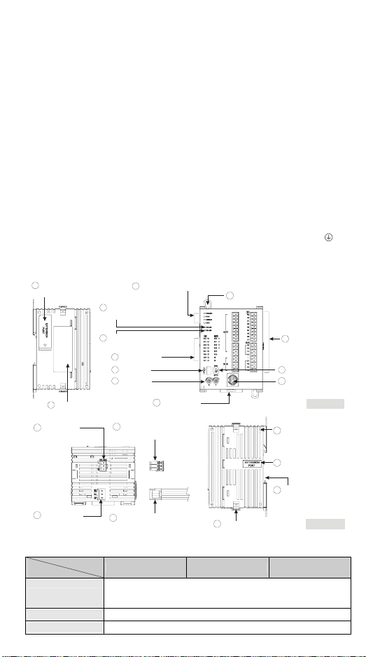
Product Profile
1
Left-side module
connection port
2
Nameplate
14
COM2 port
(RS-485)
3
POWER/RUN/ERROR/USB indicator
4
COM1 communication
indicator (RS-232)
5
COM2 communication
indicator (RS-485)
6
I/O indicator
7
USB port
8
VR0/VR1
9
DIN rail clip
16
3PIN removable terminal
(standard component)
10
Direct fastening hole
V0+
I0+
VI0-
V1+
I1+
VI1-
V2+
I2+
VI2-
V3+
I3+
VI3-
FE
VO0
IO0
VO1
IO1
AG
11
I/O terminal
12
RUN/STOP switch
13
COM1 port
(RS-232)
I/O module
18
positioning hole
[ Figure 1 ]
15
Power input
port
17
Power input connection
cable (standard component)
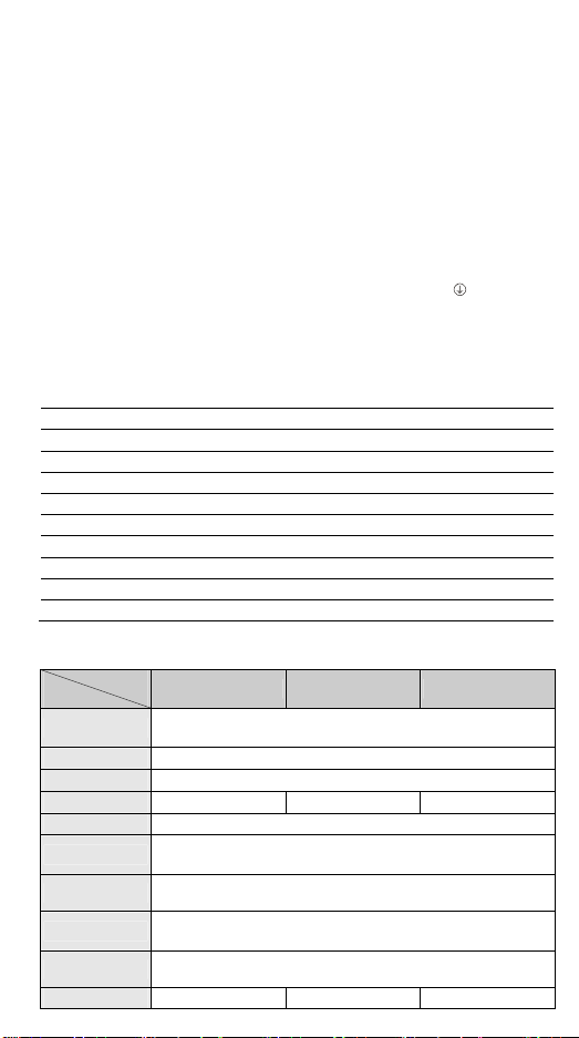
Electrical Specifications
Model
Item
Power supply voltage
Inrush current Max. 7.5A@24VDC
Fuse capacity 2.5A/30VDC, Polyswitch
DVP20SX211R DVP20SX211T DVP20SX211S
24VDC (-15% ~ 20%)
(with counter-connection protection on the polarity of DC input power)
DVPPS01(PS02): input 100-240VAC, output 24VDC/1A(PS02: 2A)
- 1 -
21
I/O module fastening clip
19
I/O module
connection port
20
Mounting slot
(35mm)
[ Figure 2 ]
Model
Item
DVP20SX211R DVP20SX211T DVP20SX211S
Power consumption 4.7W 4W 4W
Insulation resistance > 5MΩ (all I/O point-to-ground: 500VDC)
ESD: 8KV Air Discharge
Noise immunity
Grounding
Operation / storage
Vibration / shock
resistance
Weight (g) 243g 224g 227g
Spec.
Items
EFT: Power Line: 2KV, Digital I/O: 1KV, Analog & Comm. I/O: 1KV
RS: 26MHz ~ 1GHz, 10V/m
The diameter of grounding wire cannot be smaller than the wire
diameter of terminals 24V and 0V (All DVP units should be grounded
directly to the ground pole).
Operation: 0°C ~ 55°C (temp.), 50 ~ 95% (humidity), Pollution degree2
Storage: -25°C ~ 70°C (temp.), 5 ~ 95% (humidity)
International standards: IEC61131-2, IEC 68-2-6 (TEST
Fc)/IEC61131-2 & IEC 68-2-27 (TEST Ea)
Input Point
24VDC (-15% ~ 20%) single common port input
Input No. X0, X2 X1, X3 X4 ~ X7
Input type DC (SINK or SOURCE)
Input Current (± 10%) 24VDC, 5mA
Input impedance 4.7K Ohm
Action level
Response
time
Filter time Adjustable within 0 ~ 20ms by D1020 (Default: 10ms)
Spec.
Items
OffOn > 15VDC
OnOff < 5VDC
OffOn < 2.5μs < 10μs < 20us
OnOff < 5μs < 20μs < 50us
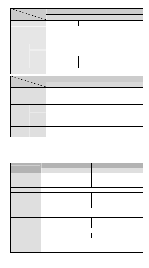
Output Point
Relay Transistor
Output No. Y0 ~ Y5 Y0, Y2 Y1, Y3 Y4, Y5
Max. frequency 1Hz 100kHz 10kHz 1kHz
Working voltage 250VAC, < 30VDC
SX211T: 0.5A/1 point (3A/ZP)
SX211S: 0.3A/1 point (1.8A/UP)
Max. load
Resistive 1.5A/1 point (5A/COM)
Inductive
#2
5 ~ 30VDC
15W (30VDC)
#1
Lamp 20WDC/100WAC 2.5W (30VDC)
Response
time
#1: DVP20SX211T: UP, ZP must work with external auxiliary power supply 24VDC (-15% ~
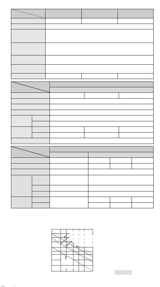
#2: Life curves
OffOn 2μs 20μs 100μs
OnOff
Approx. 10 ms
3μs 30μs 100μs
+20%), rated consumption approx. 3mA/point.
DVP20SX211S: UP, ZP must work with external auxiliary power supply 5~30VDC, rated
consumption approx. 5mA/point.
3000
2000
1000
)
3
0
500
1
X
300
(
n
200
o
i
t
a
100
r
e
p
O
50
0.1
120VAC Resistive
30VDC Inductive(t=7ms)
240VAC Inductive(cos 0.4)ψ=
30VDC
Inductiv e
( t=40 ms)
0.2
0.5
0.3 0.7
120VAC Inductive(cos =0.4)
12
Contact
Current(A)
ψ
[ Fig ure 3 ]
- 2 -
A/D and D/A Specifications
Items
Analog I/O range ±10V ±20mA 4 ~ 20mA#1±10V 0 ~ 20mA 4 ~ 20mA
Digital conversion
range
Resolution #2 12-bit
Input impedance > 1MΩ 250Ω -
Output impedance - 0.5Ω or lower
Tolerance carried
impedance
Overall accuracy
Response time 2ms (set up in D1118)
Absolute input
range
Digital data format 2’s complement of 16-bit, 12 significant bits
Average function Provided (set up in D1062)
Isolation method No Isolation between digital circuit and analog circuit
Protection
#1: Please refer to the detailed explanation of D1115.
#2: Resolution formula
Analog Input (A/D) Analog Output (D/A)
Voltage Current Voltage Current
20V
5mV( =
#3: When the scan period is longer than 2ms or the set value, the setting will follow the scan
period.
#4: When the scan period is longer than 2ms, the setting will follow the scan period.
#5: When the sampling range is “1”, the present value will be read.
4000
Analog Input (A/D) Analog Output (D/A)
Voltage Current Volt age Current
±2,000 ±2,000 0 ~ +2,000 ±2,000 0 ~ +4,000 0 ~ +4,000
- > 5KΩ < 500Ω
Non-linear accuracy: ±1% of full scale within the range of PLC operation
temperature
Maximum deviation: ±1% of full scale at 20mA and +10V
#3
2ms
#4
±15V ±32mA -
#5
-
Voltage output has short circuit protection, but a long period of short
circuit may cause internal wire damage and open circuit of current output.
μΑ(10 =
40mA
4000
)
5mV( =
)
20V
4000
)
μΑ(5 =
20mA
4000
)
#1
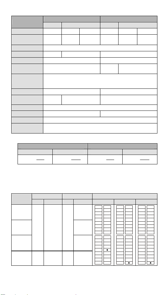
I/O Configuration
Model
Input Output
Point Type Point Type
20SX211R Relay
20SX211T
8
20SX211S
SX2-R/T/S 4
DC
(Sink Or
Source)
Analog
Input
6
2
NPN
Transistor
PNP
Transistor
Analog
output
I/O configuration
Relay NPN PNP
V0+
S/S
V0+
S/S
I0+
X0
VI0-
V1+
I1+
VI1-
V2+
I2+
VI2-
V3+
I3+
VI3-
FE
VO0
VO1
IO1
AG
I0+
X1
VI0-
X2
V1+
I1+
X3
X4
VI1-
X5
V2+
X6
I2+
X7
VI2-
C0
V3+
Y0
I3+
Y1
VI3-
Y2
FE
VO0
C1IO0
Y3
VO1
Y4
IO1
Y5
AG
V0+
X0
X1
VI0X2
V1+
X3
X4
VI1X5
V2+
X6
X7
VI2-
UP
V3+
ZP
Y0
VI3Y1
Y2
VO0
Y3IO0
Y4
VO1
Y5
IO1
S/S
I0+
X0
X1
X2
I1+
X3
X4
X5
I2+
X6
X7
UP
I3+
ZP
Y0
FE
Y1
Y2
Y3IO0
Y4
Y5
AG
Dimension & Installation
Please install the PLC in an enclosure with sufficient space around it to allow heat
dissipation, as shown in the [Figure 5].
- 3 -

Direct Mounting: Please use M4 screw according to the dimension of the product.
DIN Rail Mounting: When mounting the PLC to 35mm DIN rail, be sure to use the
retaining clip to stop any side-to-side movement of the PLC and reduce the chance of
wires being loose. The retaining clip is at the bottom of the PLC. To secure the PLC to
DIN rail, pull down the clip, place it onto the rail and gently push it up. To remove the
PLC, pull the retaining clip down with a flat screwdriver and gently remove the PLC from
DIN rail.
109.4
70
53.2
V0+
I0+
VI0-
V1+
I1+
VI1-
V2+
I2+
VI2-
V3+
I3+
VI3-
101
FE
VO0
IO0
VO1
IO1
AG
3 90 3
Unit: mm
[ Figu re 4 ]
Wiring
1. Use 22-16AWG (1.5mm) single or multiple core wire
on I/O wiring terminals. See the figure in the right hand
side for its specification. PLC terminal screws should be
tightened to 1.90 kg-cm (1.65 in-lbs) and please use only
60/75ºC copper conductor.
2. DO NOT wire empty terminal and place the I/O signal cable in the same wiring
circuit.
3. DO NOT drop tiny metallic conductor into the PLC while screwing and wiring. Tear
off the sticker on the heat dissipation hole for preventing alien substances from
dropping in, to ensure normal heat dissipation of the PLC.
Safety Wiring
Since DVP-SX2 is only compatible with DC power supply, Delta power supply modules
(DVPPS01/DVPPS02) are suitable power supplies for DVP-SX2. Users are suggested
to install the protection circuit at the power supply terminal to protect DVPPS01 or
DVPPS02. See the figure below.
22-16AWG
< 1.5mm
○1 AC power supply:100 ~ 240VAC, 50/60Hz ○
Emergency stop: This button cuts off the system power supply when accidental
○3
emergency takes place.
○4 Power indicator ○
2
Breaker
5
AC power supply load
- 4 -
○6 Power supply circuit protection fuse (2A) ○
○8 DC power supply output: 24VDC, 500mA ○
7
DVPPS01/DVPPS02
9
DVP-PLC (main processing unit)
○10 Digital I/O module
Power Supply
The power input of DVP-SX2 series is DC. When operating DVP-SX2 series, please
note the following points:
1. The power is connected to the two terminals, 24VDC and 0V, and the range of power
is 20.4 ~ 28.8VDC. If the power voltage is less than 20.4VDC, PLC will stop running,
all outputs will go “Off” and ERROR indicator will flash continuously.
2. The power shutdown of less than 10 ms will not affect the operation of the PLC.
However, power shutdown time that is too long or the drop of power voltage will stop
the operation of the PLC and all outputs will go OFF. When the power returns to
normal status, the PLC will automatically resume operation. (Care should be taken
on the latched auxiliary relays and registers inside the PLC when programming).
Input Point Wiring
There are 2 types of DC inputs, SINK and SOURCE. (See the example below. For
detailed point configuration, please refer to the specification of each model.)
DC Signal IN – SINK mode
Input point loop equivalent circuit
+24V
24G
S/S
X0
X1
[ Fig ure 7 ]
DC Signal IN – SOURCE mode
Input point loop equivalent circuit
+24V
24G
S/S
X0
X1
[ Figure 8 ]
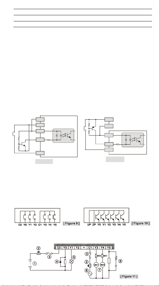
Output Point Wiring
1. DVP-SX2 series have three output modules, relay and transistor (NPN/PNP). Be
aware of the connection of shared terminals when wiring output terminals.
2. Output terminals, Y0, Y1, and Y2, of relay models use C0 common port; Y3, Y4, and
Y5 use C1 common port; as shown in the [Figure 9]. When output points are enabled,
their corresponding indicators on the front panel will be on.
3. Output terminals, Y0 ~Y5 of transistor (NPN/PNP) models use UP, ZP common port;
as shown in the [Figure 10].
4. Isolation circuit: The optical coupler is used to isolate signals between the circuit
inside PLC and input modules.
Relay (R) output circuit wiring
- 5 -

1
○
DC power supply ○2Emergency stop: Uses external switch
○3 Fuse: Uses 5~10A fuse at the shared terminal of output contacts to protect the output circuit
○4 Transient voltage suppressor (SB360 3A 60V): To extend the life span of contact.
1. Diode suppression of DC load: Used when in smaller power (Figure 12a)
2. Diode + Zener suppression of DC load: Used when in larger power and frequent On/Off
(Figure 12b)
○5 Incandescent light (resistive load) ○
○7 Manually exclusive output: For example, Y3 and Y4 control the forward running and reverse
running of the motor, forming an interlock for the external circuit, together with the PLC
internal program, to ensure safe protection in case of any unexpected errors.
6
AC power supply
○8 Absorber: To reduce the interference on AC load (Figure 13)
Transistor (T) output circuit wiring
Transistor output - NPN type (SX211T): Transistor output - PNP type (SX211S):
1
○
DC power supply ○2Emergency stop ○3Circuit protection fuse
○4 The output of the transistor model is “open collector”. If Y0/Y1 is set to pulse output, the
output current has to be bigger than 0.1A to ensure normal operation of the model.
1. Diode suppression: Used when in smaller power (Figure 15a)
2. Diode + Zener suppression: Used when in larger power and frequent On/Off (Figure 15b)
○5 Manually exclusive output: For example, Y3 and Y4 control the forward running and reverse
running of the motor, forming an interlock for the external circuit, together with the PLC
internal program, to ensure safe protection in case of any unexpected errors.
- 6 -

A/D and D/A External Wiring
A
A/D: Active A/D: Passive
Volt age inp ut
1
+
U
IN
-
2
Current input
+
U
IN
-
3
Te rmin al
power moduleof
5
D/A
8
AC drive, recorder,
scale value...
8
AC drive, recorder,
scale value...
4
4
Grounding
6
Volt age out put
7
Current output
Shielded
cable
Shielded
cable
Isolation wire
Isolation wire
(100 or less)
[ Fig ure 16 ]
4
4
CH1
CH3
CH1
CH2
V0+
V3+
24V
[ Figure 18 ]
I0+
VI0-
I3+
VI3FE
0V
VO0
VO1
IO1
IO0
G
1
Volt age in put
+
U
IN
-
2
Current input
-
+
Te rmi nal o f
power module
3
Grounding
5
Note: When the A/D module is
connected to current signals, make
sure to short-circuit “V+” and “I+”
terminals.
RS-485 Wiring
1 2 2
D+ D- SG D+ D- SG SG D+ D-
3
4
4
Shielded
cable
Shielded
cable
(100 or less)
3
CH1
V0+
I0+
V0-
CH3
V3+
I3+
VI3-
FE
0V
24V
[ Figure 17 ]
4
○1 Master node ○
○3 Terminal resistor ○
Note: 1. Terminal resistors are suggested to be connected to master and the last slave with
resistor value of 120Ω.
2. To ensure communication quality, please apply double shielded twisted pair cable
(20AWG) for wiring.
3. When voltage drop occurs between the internal ground references of two
connect the systems with Signal Ground point (SG) for achieving equal potential
between systems so that a stable communication can be obtained.
4
2
4
- 7 -
Figure 19
Slave node
Shielded cable
systems,
………………………………………………………………… 繁體中文 ………………………………………………………………………
感謝您採用台達 DVP 系列可程式控制器。DVP-SX2 為20 點(8 數位輸入點 + 6 數位輸
出點 + 4 點類比輸入 + 2 點類比輸出)PLC 主機,提供豐富的指令集,並具有 16k steps
的程式記憶體,可連接薄型全系列 I/O 模組,包含數位輸入/輸出(最大輸入/輸出擴充點
數可達 480 點)、類比模組(A/D、D/A 轉換及溫度單元)及新型高速 I/O 模組等各類機型。
兩組高速(100kHz)脈波輸出、新增一組兩軸補間指令,可滿足各種應用場合,並且體
積小,安裝容易。
a 本安裝說明書提供給使用者電氣規格、功能規格、安裝配線之相關注意事項。其他詳
細之程式設計及指令說明請見 DVP-SX2 操作手冊【程式篇】,選購之周邊裝置詳細說
明請見該產品隨機安裝說明書。
a 本機為開放型 (OPEN TYPE) 機殼,因此使用者使用本機時,必須將之安裝於具防
塵、防潮及免於電擊/衝擊意外之外殼配線箱內。另必須具備保護措施(如:特殊之工
具或鑰匙才可打開)防止非維護人員操作或意外衝擊本體,造成危險及損壞。
a 交流輸入電源不可連接於輸入/出信號端,否則可能造成嚴重損壞,請在上電之前再
次確認電源配線。請勿在上電時觸摸任何端子。本體上之接地端子 務必正確的接
地,可提高產品抗雜訊能力。
產品外觀部位介紹
詳細外觀圖示請參閱英文版頁碼 1 之 [Figure 1] 及 [Figure 2]。
○1 左側高速 I/O 模組連接口 ○
○2 銘牌 ○
○3 電源、運行、錯誤及 USB 狀態指示燈 ○
○4 COM1 (RS-232) 通訊指示燈 ○
○5 COM2 (RS-485) 通訊指示燈 ○
○6 輸入/輸出點指示燈 ○
○7 USB 通訊口 ○
○8 VR0/VR1 ○
○9 DIN 軌固定扣 ○
○10 直接固定孔 ○
12
RUN/STOP 開關
13
COM1 (RS-232) 通訊口
14
COM2 (RS-485) 通訊口
15
電源輸入口
16
3PIN 脫落式端子 (標準附件)
17
電源輸入連接線 (標準附件)
18
I/O 模組定位孔
19
I/O 模組連接口
20
DIN 軌槽 (35mm)
21
I/O 模組固定扣
○11 輸入/輸出端子
電氣規格
機種
項目
電源電壓
突入電流 Max. 7.5A@24VDC
電源保險絲容量 2.5A/30VDC,可恢復式(Polyswitch)
消耗電力 4.7W 4W 4W
絕緣阻抗 > 5MΩ (所有輸出/入點對地之間 500VDC)
雜訊免疫力
接地
操作/儲存環境
耐振動/衝擊
重量 243g 224g 227g
DVP20SX211R DVP20SX211T DVP20SX211S
24VDC (-15% ~ 20%) (具直流輸入電源極性反接保護)
DVPPS01(PS02):輸入 100-240VAC,輸出 24VDC/1A (PS02: 2A)
ESD: 8KV Air Discharge. RS: 26MHz ~ 1GHz, 10V/m.
EFT: Power Line: 2KV, Digital I/O: 1KV, Analog & Comm. I/O: 1KV.
接地配線之線徑不得小於電源端配線線徑(多台PLC 同時使用時,請務必
單點接地)
操作:0ºC ~ 55ºC(溫度)50 ~ 95%(濕度)污染等級 2
儲存:-25ºC ~ 70ºC(溫度)5 ~ 95%(濕度)
國際標準規範 IEC61131-2, IEC 68-2-6 (TEST Fc)/IEC61131-2 & IEC
68-2-27 (TEST Ea)
- 8 -

機種
項目
輸入點 No.
X0, X2 X1, X3 X4 ~ X7
輸入點電氣規格
24VDC (-15% ~ 20%) 單端共點輸入
輸入接線型式 由端子 S/S 變換接線為 SINK 或 SOURCE
輸入信號電壓(±10%)
輸入點阻抗
動作位准
反應時間
雜訊抑制
濾波時間 由 D1020 可作 0 ~ 20 ms 的調整 (預設:10ms)
OffOn > 15VDC
OnOff < 5VDC
OffOn < 2.5μs < 10μs < 20μs
OnOff < 5μs < 20μs < 50μs
機種
項目
輸出點 No.
最高交換頻率
電壓規格
繼電器 電晶體
Y0 ~ Y5 Y0, Y2 Y1, Y3 Y4, Y5
1Hz 100kHz 10kHz 1kHz
250VAC, < 30VDC
電阻性 1.5A/1 點 (5A/COM)
電流規格
反應時間
電感性
燈泡
OffOn 2μs 20μs 100μs
OnOff
#2
20WDC/100WAC 2.5W (30VDC)
約 10 ms
24VDC, 5mA
4.7K Ohm
輸出點電氣規格
#1
5 ~ 30VDC
SX211T: 0.5A/1 點 (3A/ZP)
SX211S: 0.3A/1 點 (1.8A/UP)
15W (30VDC)
3μs 30μs 100μs
#1:DVP20SX211T:UP, ZP 必須外加輔助電源 24VDC (-15% ~ +20%),額定消耗約 3mA/點。
DVP20SX211S:UP, ZP 必須外加輔助電源 5 ~ 30VDC,額定消耗約 5mA/點。
#2:生命週期曲線圖請參閱英文版[Figure 3]。
AD/DA 規格
項 目
類比輸入∕輸出範圍
數位轉換範圍
解析度 #2 12-bit
輸入阻抗 > 1MΩ 250 Ω -
輸出阻抗 - 0.5Ω or lower
容許負載阻抗 - > 5KΩ < 500Ω
總和精密度
回應時間 2ms (可由D111 8 設定)
絕對輸入範圍 ±15V ±32mA -
數位資料格式 16 位 2 補數(有效位 12 bits)
平均功能 是 (由 D1062 設定)
隔離方式 數位及類比電路間未隔離
保護
#1:詳細資訊請參考 D 1115 說明。
類比輸入 (A/D) 類比輸出 (D/A)
電壓輸入 電流輸入 電壓輸出 電流輸出
#1
±10V ±20mA 4 ~ 20mA
±10V 0 ~ 20mA 4 ~ 20mA
±2,000 ±2,000 0 ~ +2,000 ±2,000 0 ~ +4,000 0 ~ +4,000
非線性精度:±1%在整個溫度範圍內滿刻度時
最大誤差:±1%在滿刻度 20mA 及+10V 時
#3
2ms
#5
-
#4
電壓輸出有短路保護但須注意長時間短路仍有可能造成內部線路損壞,
電流輸出可開路。
- 9 -
#1

#2:解析度計算
類比電壓輸入 類比電流輸入 類比電壓輸出 類比電流輸出
20V
)
5mV( =
#3:當掃描週期大於 2ms 或設定值時,以掃描週期為主。
#4:當掃描週期大於 2ms 時,以掃描週期為主。
#5:當平均次數 D1062 為 1 時,即是讀取現在值。
4000
μΑ(10 =
40mA
4000
)
5mV( =
20V
4000
)
μΑ(5 =
20mA
4000
)
輸入/輸出配置
機種
20SX211R 繼電器
20SX211T 電晶體(NPN)
20SX211S
20SX211R/T/S 4 類比輸入 2 類比輸出
輸入單元 輸出單元 I/O 配置
點數 形式 點數 形式 繼電器 電晶體
直流
8
(Sink or Source)
6
電晶體(PNP)
請參閱英
文版圖示
請參閱英
文版圖示
產品尺寸與安裝方式
產品尺寸圖請參閱英文版頁碼 3 之 [Figure 4],單位:mm。
PLC 在安裝時,請裝配於封閉式之控制箱內,其周圍應保持一定之空間,以確保 PLC 散
熱功能正常,請參閱英文版頁碼 3 之[Figure 5]。
直接鎖螺絲方式:請依產品外型尺寸並使用M4 螺絲。
DIN 鋁軌之安裝方法:適用於 35mm 之 DIN 鋁軌。在將主機掛上鋁軌時,請先將主機
(或 I/O 模組)下方之固定塑膠片,以一字形起子插入凹槽並向外撐開拉出(請參閱英
文版頁碼 4 之[Figure 5]),再將主機(或 I/O 模組)掛上鋁軌,之後將固定塑膠片壓扣
回去即可。欲取下主機時,同樣以一字形起子先將固定塑膠片撐開,再將主機以往外向
上的方式取出即可。該固定機構塑膠片為保持型,因此撐開後便不會彈回去。
配線端子
1. 輸出/入配線端請使用 22-16AWG (1.5mm) 單蕊祼線或多蕊線,端子規格如頁碼3 之圖
示。PLC 端子鏍絲扭力為 1.90 kg-cm (1.65 in-lbs)。只能使用 60/75°C 的銅導線。
2. 空端子請勿配線。輸入點信號線與輸出點等動力線請勿置於同一線糟內。
3. 鎖鏍絲及配線時請避免微小的金屬導體掉入 PLC 內部,並在配線完成後,將位於 PLC
上方散熱孔位置的防異物掉入之貼紙撕去,以保持散熱良好。
電源端
DVP-SX2 機種為直流電源輸入,在使用上應注意下列事項:
1. 電源請接於 24VDC 及 0V 兩端,電源範圍為 20.4 ~ 28.8VDC,當電源電壓低於
20.4VDC 時,PLC 會停止運轉,輸出全部Off,ERROR LED 快速閃爍。
2. 當停電時間低於 10ms 時,PLC 不受影響繼續運轉,當停電時間過長或電源電壓下降
將使 PLC 停止運轉,輸出全部 Off,當電源恢復正常時,PLC 亦自動回復運轉。(PLC
內部具停電保持的輔助繼電器及暫存器,使用者在規劃程式設計時應特別注意使用。)
安全配線回路
由於 DVP-SX2 的電源為 DC Only 的機種,因此可搭配台達之電源供應模組
(DVPPS01/DVPPS02) 提供電源給 DVP-SX2。為保護 DVPPS01/DVPPS02,建議可在
電源的輸入回路端配置如下的保護回路,配置圖請參閱英文版頁碼 4 之[Figure 6]所示:
○1 交流電源供應:100 ~ 240VAC, 50/60Hz ○
○3 緊急停止:為預防突發狀況發生,設置緊急停止按鈕,可在狀況發生時,切斷系統電源。
○4 電源指示燈 ○
○6 電源回路保護用保險絲(2A) ○
○8 直流電源供應輸出:24VDC,500mA ○
○10 數位輸入/輸出模組
2
斷路器
5
交流電源負載
7
DVPPS01/DVPPS02 本體
9
DVP PLC 本體
- 10 -

輸入點之配線
輸入點之入力信號為直流電源 DC 輸入型式,共有兩種接法:SINK 及 SOURCE,其定義
與輸入點回路等效電路配線圖,請參閱英文版頁碼 4~5 之[Figure 7]及[Figure 8]。
輸出點之配線
1. DVP-SX2 系列 PLC 輸出模組共有三種:繼電器、電晶體-NPN 與電晶體-PNP。輸出
端在實際配線時,應特別注意共用端的連接。
2. 繼電器機種輸出端 Y0、Y1、Y2 用 C0 共同端,Y3、Y4、Y5 用C1 共同端,請參閱英
文版頁碼 5 之[Figure 9]。動作指示:當輸出點動作時,正面的該點指示燈亮。
3. 電晶體 (NPN/PNP) 機種輸出端 Y0 ~Y5 用 UP、ZP 共同端,請參閱英文版頁碼 5 之
[Figure 10]。
4. 隔離回路:PLC 內部回路與輸入模組之間使用光耦合器作信號隔離。
繼電器輸出回路配線
詳細配線圖請參閱英文版頁碼 5 之 [Figure 11] ~ [Figure 13]。
1
○
直流電源供給 ○2緊急停止:使用外部開關
○3 保險絲:使用 5 ~ 10A 的保險絲容量於輸出接點的共用點,保護輸出點回路
○4 突波吸收二極體:可增加接點壽命。
1. DC 負載電源之二極體抑制:功率較小時使用(請參閱英文版頁碼 5 之[Figure 12a])
2. DC 負載電源之二極體+Zener 抑制:大功率且 On/Off 頻繁時使用(請參閱英文版頁碼
5 之[Figure 12b])
○5 白熾燈(電阻性負載) ○
○7 互斥輸出:例如,將 Y3 與 Y4 用以控制對應馬達的正轉及反轉,使外部電路形成互鎖,配
合 PLC 內部程式,確保任何異常突發狀況發生時,均有安全的保護措施。
6
交流電源供給
○8 突波吸收器:可減少交流負載上的雜訊(請參閱英文版頁碼5 之[Figure 13])
電晶體輸出回路配線
詳細配線圖請參閱英文版頁碼 6 之 [Figure 14a] ~ [Figure 15b]。
1
○
直流電源供應 ○
○4 突波吸收二極體:可增加接點壽命。
1. DC 負載電源之二極體抑制:功率較小時使用(請參閱英文版頁碼 6 之[Figure 15a])
2. DC 負載電源之二極體+Zener 抑制:大功率且On/Off 頻繁時使用(請參閱英文版頁碼
6 之[Figure 15b])
○5 互斥輸出:例如,將 Y3 與 Y4 用以控制對應馬達的正轉及反轉,使外部電路形成互鎖,配
合 PLC 內部程式,確保任何異常突發狀況發生時,均有安全的保護措施。
2
緊急停止 ○
3
電路回路保護用保險絲
A/D 與 D/A 外部配線
詳細配線圖請參閱英文版頁碼 7 之 [Figure 16] ~ [Figure 18]。
○1 電壓輸入 ○
○3 接至電源模組之 端 ○
○5 第三種接地(接地阻坑 100Ω以下) ○
○7 電流輸出 ○
註:如果連接電流訊號時,V+ 及I+ 端子請務必短路。
2
電流輸入
4
隔離線
6
電壓輸出
8
交流馬達驅動器、記錄器、比例閥…
RS-485 建議接線
詳細接線圖請參閱英文版頁碼 7 之[Figure 19]。
○1 主站 ○
○3 終端電阻 ○
附註:1. 終端電阻建議連接於主站及最後一台從站上,且其電阻值建議為 120Ω 。
2. 為確保連線品質,線材建議使用具有雙層遮蔽線之通訊雙絞線(20AWG)。
3. 當兩個系統內部地準位存在壓降,可透過連接 SG (Signal Ground) 讓地準位等電位,
使通訊更加穩定。
- 11 -
2
4
從站
遮蔽線

…………………………………………………………………… 简体中文 ……………………………………………………………………
感谢您采用台达 DVP 系列可编程控制器。DVP-SX2 为 20 点(8 数字量输入点 + 6 数字
量输出点 + 4 模拟量输入 + 2 模拟量输出)LC 主机,提供丰富的指令集,并具有 16k steps
的程序内存,可连接 SS/SA/SX/SC/SV 全系列 I/O 模块,包含数字量输入/输出(最大输
入/输出扩展点数可达 480 点)、模拟量模块(A/D、D/A 转换及温度单元)及新型高速
I/O 模块等各类机型。四组高速(100kHz)脉冲输出、新增一组两轴插补指令,可满足各
种应用场合,并且体积小,安装容易。
a 本安装说明书提供给使用者电气规格、功能规格、安装配线的相关注意事项。其它详
细的程序设计及指令说明请见 DVP-SX2 操作手册【程序篇】,选购的周边装置详细说
明请见该产品随机安装说明书。
a 本机为开放型 (OPEN TYPE) 机种,因此使用者使用本机时,必须将的安装于具防尘、
防潮及免于电击/冲击意外的外壳配线箱内。另必须具备保护措施(如:特殊的工具
或钥匙才可打开)防止非维护人员操作或意外冲击本体,造成危险及损坏。
a 交流输入电源不可连接于输入/出信号端,否则可能造成严重损坏,请在上电的前再
次确认电源配线。请勿在上电时触摸任何端子。本体上的接地端子 务必正确的接
地,可提高产品抗干扰能力。
產品外觀部位介紹
详细外观图示请参阅英文版页码 1 之 [Figure 1] 及 [Figure 2]。
○1 左侧高速 I/O 模块连接口 ○
○2 铭牌 ○
○3 电源、运行、错误及 USB 状态指示灯 ○
○4 COM1(RS-232) 通讯指示灯 ○
○5 COM2(RS-485) 通讯指示灯 ○
○6 输入/输出点指示灯 ○
○7 USB 通讯口 ○
○8 VR0/VR1 ○
○9 DIN 轨固定扣 ○
○10 直接固定孔 ○
12
RUN/STOP 开关
13
COM1(RS-232) 通讯口
14
COM2(RS-485) 通讯口
15
电源输入口
16
3PIN 脱落式端子 (标准附件)
17
电源输入连接线 (标准附件)
18
I/O 模块定位孔
19
I/O 模块连接口
20
DIN 轨槽 (35mm)
21
I/O 模块固定扣
○11 输入/输出端子
電氣規格
机种
项目
电源电压
突入电流 Max. 7.5A@24VDC
电源保险丝容量 2.5A/30VDC,可恢复式 (Polyswitch)
消耗电力 4.7W 4W 4W
绝缘阻抗 > 5MΩ (所有输出/入点对地之间 500VDC)
干扰免疫力
接地
操作/储存环境
耐振动/冲击
重量 243g 224g 227g
DVP20SX211R DVP20SX211T DVP20SX211S
24VDC (-15% ~ 20%) (具直流输入电源极性反接保护)
DVPPS01(PS02):输入 100-240VAC,输出 24VDC/1A (PS02: 2A)
ESD: 8KV Air Discharge. RS: 26MHz ~ 1GHz, 10V/m.
EFT: Power Line: 2KV, Digital I/O: 1KV, Analog & Comm. I/O: 1KV.
接地配线的线径不得小于电源端配线线径(多台 PLC 同时使用时,请务必
单点接地)
操作:0ºC ~ 55ºC(温度)50 ~ 95%(湿度)污染等级 2
储存:-25ºC ~ 70ºC(温度)5 ~ 95%(湿度)
国际标准规范 IEC61131-2, IEC 68-2-6 (TEST Fc)/IEC61131-2 & IEC
68-2-27 (TEST Ea)
- 12 -
机种
项目
输入点 No.
X0, X2 X1, X3 X4 ~ X7
输入点电气规格
24VDC (-15% ~ 20%) 单端共点输入
输入接线型式 由端子 S/S 变换接线为漏型或源型
输入信号电压(±10%)
输入阻抗
动作临界点
反应时间
干扰抑制
滤波时间 由 D1020 可作 0 ~ 20 ms 的调整 (预设:10ms)
机种
项目
输出点 No.
最高交换频率
电压规格
OffOn > 15VDC
OnOff < 5VDC
OffOn < 2.5μs < 10μs < 20μs
OnOff < 5μs < 20μs < 50μs
继电器 晶体管
Y0 ~ Y5 Y0, Y2 Y1, Y3 Y4, Y5
1Hz 100kHz 10kHz 1kHz
250VAC, < 30VDC
电阻性 1.5A/1 点 (5A/COM)
电流规格
反应时间
电感性
灯泡
OffOn 2μs 20μs 100μs
OnOff
#2
20WDC/100WAC 2.5W (30VDC)
约 10 ms
24VDC, 5mA
4.7K Ohm
输出点电气规格
#1
5 ~ 30VDC
SX211T: 0.5A/1 点 (3A/ZP)
SX211S: 0.3A/1 点 (1.8A/UP)
15W (30VDC)
3μs 30μs 100μs
#1:DVP20SX211T:UP, ZP 必须外加辅助电源 24VDC (-15% ~ +20%),额定消耗约 3mA/点。
DVP20SX211S:UP, ZP 必须外加辅助电源 5 ~ 30VDC,额定消耗约 5mA/点。
#2:生命周期曲线图请参阅英文版[Figure 3]。
A/D 与 D/A 规格
项 目
模拟量输入/输出
范围
数字转换范围 ±2,000 ±2,000 0 ~ +2,000 ±2,000 0 ~ +4,000 0 ~ +4,000
分辨率 #2 12-bit
输入阻抗 > 1MΩ 250 Ω -
输出阻抗 - 0.5Ω or lower
允许负载阻抗 - > 5KΩ < 500Ω
总和
精密度
响应时间 2ms (可由 D111 8 设定)
绝对输入范围 ±15 V ±32mA 数字数据格式 16 位 2 补码(有效位 12 bits)
平均功能 是 (由 D1062 设定)
隔离方式 数字及模拟电路间未隔离
保护
#1:详细信息请参考 D 1115 说明。
模拟量输入 (A/D) 模拟量输出 (D/A)
电压输入 电流输入 电压输出 电流输出
#1
±10V ±20mA 4 ~ 20mA
非线性精度:±1%在整个温度范围内满刻度时
最大误差:±1%在满刻度 20mA 及+10V 时
电压输出有短路保护但须注意长时间短路仍有可能造成内部线路损坏,
电流输出可开路。
±10V 0 ~ 20mA 4 ~ 20mA
#3
2ms
#5
-
#4
- 13 -
#1

#2:分辨率计算
模拟量输电压输入 模拟量输电流输入 模拟量输电压输出 模拟量输电流输出
20V
)
5mV( =
4000
#3:当扫描周期大于 2ms 或设定值时, 以扫描周期为主。
#4:当扫描周期大于 2ms 时,以扫描周期为主。
#5:当平均次数 D1062 为 1 时,即读取现在值。
40mA
)
μΑ(10 = )
4000
5mV( =
20V
4000
20mA
)
μΑ(5 =
4000
輸入/輸出配置
机种
20SX211R 继电器
20SX211T 晶体管(NPN)
20SX211S
20SX211R/T/S 4 模拟量输入 2 模拟量输出
输入单元 输出单元 I/O 配置
点数 形式 点数 形式 继电器 晶体管
直流
8
(漏型或源型)
6
晶体管(PNP)
请参阅英文
版图示
请参阅英文
版图示
產品尺寸與安裝方式
产品尺寸图请参阅英文版页码 3 之 [Figure 4],单位:mm。
PLC 在安装时,请装配于封闭式的控制箱内,其周围应保持一定的空间,以确保 PLC 散
热功能正常,请参阅英文版页码 3 的[Figure 5]。
直接锁镙丝方式:请依产品外型尺寸并使用 M4 镙丝。
DIN 铝轨的安装方法:适用于 35mm 的 DIN 铝轨。在将主机挂上铝轨时,请先将主机
(或 I/O 模块)下方的固定塑料片,以一字形起子插入凹槽并向外撑开拉出(请参阅英
文版页码 4 的[Figure 5]),再将主机(或 I/O 模块)挂上铝轨,之后将固定塑料片压扣
回去即可。欲取下主机时,同样以一字形起子先将固定塑料片撑开,再将主机以往外向
上的方式取出即可。该固定机构塑料片为保持型,因此撑开后便不会弹回去。
配線端子
1. 输出/入配线端请使用 22-16AWG (1.5mm) 单蕊祼线或多蕊线,端子规格如页码 3 之图
示。PLC 端子镙丝扭力为 1.90 kg-cm (1.65 in-lbs)。只能使用 60/75°C 的铜导线。
2. 空端子请勿配线。输入点信号线与输出点等动力线请勿置于同一线糟内。
3. 锁镙丝及配线时请避免微小的金属导体掉入 PLC 内部,并在配线完成后,将位于 PLC
上方散热孔位置的防异物掉入的贴纸撕去,以保持散热良好。
電源端
DVP-SX2 机种为直流电源输入,在使用上应注意下列事项:
1. 电源请接于 24VDC 及 0V 两端,电源范围为 20.4VDC ~ 28.8VDC,当电源电压低于
20.4VDC 时,PLC 会停止运行,输出全部Off,ERROR LED 快速闪烁。
2. 当停电时间低于 10ms 时,PLC 不受影响继续运转,当停电时间过长或电源电压下降
将使 PLC 停止运转,输出全部 Off,当电源恢复正常时,PLC 亦自动回复运转。(PLC
内部具停电保持的辅助继电器及寄存器,使用者在规划程序设计时应特别注意使用。)
安全配線回路
由于 DVP-SX2 的电源为 DC Only 的机种,因此可搭配台达的电源供应模块
(DVPPS01/DVPPS02) 提供电源给 DVP-SX2。为保护 DVPPS01/DVPPS02,建议可在
电源的输入回路端配置如下的保护回路,配置图请参阅英文版页码 4 的[Figure 6]所示:
○1 交流供应电源:100 ~ 240VAC, 50/60Hz ○
○3 紧急停止:为预防突发状况发生,设置紧急停止按钮,可在状况发生时,切断系统电源。
○4 电源指示灯 ○
○6 电源回路保护用保险丝(2A) ○
○8 直流供应电源输出:24VDC,500mA ○
○10 数字量输入/输出模块
2
断路器
5
交流电源负载
7
DVPPS01/DVPPS02 本体
9
DVP PLC 本体
- 14 -

輸入點的配線
输入点的接入信号为直流电源 DC 输入,DC 型式共有两种接法:漏型及源型,其定义与
输入点回路等效电路配线图,请参阅英文版页码 4~5 的[Figure 7]及[Figure 8]。
輸出點的配線
1. DVP-SX2 系列 PLC 输出模块共有三种:继电器、晶体管-NPN 与晶体管-PNP。输出
端在实际配线时,应特别注意共享端的连接。
2. 继电器机种输出端 Y0、Y1、Y2 用 C0 共同端,Y3、Y4、Y5 用 C1 共同端,请参阅英
文版页码 5 之[Figure 9]。动作指示:当输出点动作时,正面的该点指示灯亮。
3. 晶体管 (NPN/PNP) 机种输出端 Y0~Y5 共享 UP、ZP 共同端,请参阅英文版页码 5
之[Figure 10]。动作指示:当输出点动作时,正面的该点指示灯亮。
4. 隔离回路:PLC 内部回路与输入模块之间使用光耦合器作信号隔离。
继电器输出回路配线
详细配线图请参阅英文版页码 5 之 [Figure 11] ~ [Figure 13]。
1
○
直流电源供给 ○2紧急停止:使用外部开关
○3 保险丝:于输出接点的公共端使用容量 5 ~ 10A 的保险丝,保护输出点回路
○4 突波吸收二极管:可增加接点寿命。
1. DC 负载电源的二极管抑制:功率较小时使用(请参阅英文版页码 5 的[Figure 12a])
2. DC 负载电源的二极管+Zener 抑制:大功率及 On/Off 频繁时使用(请参阅英文版页码 5
的[Figure 12b])。
○5 白炽灯(电阻性负载) ○
○7 互斥输出:例如,将 Y3 与 Y4 用于控制对应马达的正转及反转,使外部电路形成互锁,配
合 PLC 内部程序,确保任何异常突发状况发生时,均有安全的保护措施。
6
交流电源供给
○8 突波吸收器:可减少交流负载上的干扰(请参阅英文版页码 5 的[Figure 13])
晶体管输出回路配线
详细配线图请参阅英文版页码 6 之 [Figure 14a] ~ [Figure 15b]。
1
○
直流供应电源 ○
○4 突波吸收二极管:可增加接点寿命。
1. DC 负载电源之二极管抑制:功率较小时使用(请参阅英文版页码 6 之[Figure 15a])
2. DC 负载电源之二极管+Zener 抑制:大功率且 On/Off 频繁时使用(请参阅英文版页码
6 之[Figure 15b])
○5
互斥输出:例如,将 Y3 与 Y4 用以控制对应马达的正转及反转,使外部电路形成互锁,配
合 PLC 内部程序,确保任何异常突发状况发生时,均有安全的保护措施。
2
紧急停止 ○
3
电路回路保护用保险丝
A/D 与 D/A 外部配線
详细配线图请参阅英文版页码 7 之 [Figure 16] ~ [Figure 18]。
○1 电压输入 ○
○3 接至电源模块之 端 ○
○5 第三种接地(接地阻坑 100Ω以下) ○
○7 电流输出 ○
注:如果连接电流讯号时,V+ 及 I+ 端子请务必短路。
2
电流输入
4
隔离线
6
电压输出
8
交流电机驱动器、记录器、比例阀…
RS-485 建議接線
详细接线图请参阅英文版页码 7 的[Figure 19]。
○1 主站 ○
○3 终端电阻 ○
附注:1. 终端电阻建议连接于主站及最后一台从站上,且其阻值建议为 120Ω。
2. 为确保联机质量,线材建议使用具有双层屏蔽线的通讯双绞线(20AWG)。
3. 当两个系统内部地准位存在压降,可透过连接 SG (Signal Ground) 让地准位等电位,
使通讯更加稳定。
- 15 -
2
4
从站
屏蔽线

………………………………………….......………………… TÜRKÇE …………...……......………………………………………………
Delta’nın DVP-SX2 modelini seçtiğiniz için teşekkürler. DVP-SX2 PLC 16K program
hafızası ile çeşitli komutlar sunar ve üzerinde 20 nokta vardır (8DI + 6 DO + 4AI + 2AO).
PLC’ye Dijital giriş/çıkış modülleri (max. 480 giriş/çıkış nokta), analog modüller (A/D, D/A
dönüştürücü ve sıcaklık üniteleri) ve yeni yüksek hızlı ilave üniteler gibi ince-tip ilave
modüller bağlanabilir. İki grup yüksek-hızlı (100kHz) pulse çıkışı ve yeni 2-eksen
interpolasyon komutları ile birçok uygulama için tatmin edici çözümler sunar. DVP-SX2
ürünü küçük ölçüsüyle kurulumu çok kolaydır.
a Bu bilgi dökümanı sadece ürünün elektriksel özellikleri, genel fonksiyonları, kurulumu
ve bağlantısı ile ilgili bilgiler sağlar. Detaylı programlama ve DVP-SX2 uygulama
komutları ile ilgili lütfen “DVP-SX2 Operation Manual: Programming” dökümanını
inceleyiniz. Opsiyonel çevre birimleri ile ilgili lütfen kutunun içindeki ürünle birlikte
gelen bilgi dökümanını inceleyiniz.
a Bu ürün AÇIK TİP bir PLC’dir. PLC ürünü toz, rutubet, elektrik şoku riski ve
titreşimden uzak yerlerde muhafaza edilmelidir. Ayrıca cihaza yetkili olmayan kişilerin
müdahale etmesini engelleyecek önlemler alınmalıdır. (Örneğin ürünün kurulduğu
panoya kilit konulması gibi). Aksi halde kullanıcılar ve/veya PLC zarar görebilir.
a Giriş/Çıkış terminallerine kesinlikle AC besleme bağlamayınız. Aksi halde ürün zarar
görebilir. Enerji vermeden önce ürünün tüm bağlantılarını kontrol ediniz.
Elektromanyetik gürültüyü önlemek için topraklamanın düzgün yapıldığına emin
olunuz. Enerjili iken ürün terminallerine müdahale etmeyiniz.
Ürün Görünüşü
İngilizce (English) bölümünde Şekil 1 [Figure 1] ve Şekil 2’ye [Figure 2] bakınız.
Elektriksel Özellikler
Model
Madde
Besleme voltajı
Sızıntı Akımı Maksimum 7.5A@24VDC
Sigorta Kapasitesi 2.5A/30VDC, Polyswitch
Güç Tük etimi 4.7W 4W 4W
Izolasyon direnci > 5MΩ (Tüm I/O nokta - ground: 500VDC)
Ses Bağışıklığı
Topraklama
Çalışma / Saklama
Titreşim / Şok direnci
Ağırlık (g) 243g 224g 227g
Özellik.
Madde
Giriş No. X0, X2 X1, X3 X4 ~ X7
Giriş Tipi DC (SINK veya SOURCE)
Giriş Akımı (± 10%) 24VDC, 5mA
Giriş Empedansı
impedance
Aktif seviye
OffOn > 15VDC
OnOff < 5VDC
DVP20SX211R DVP20SX211T DVP20SX211S
24VDC (-15% ~ 20%) (DC giriş besleme ters bağlantı koruması)
DVPPS01(PS02): giriş 100-240VAC, çıkış 24VDC/1A(PS02: 2A)
ESD: 8KV Air Discharge
EFT: Power Line: 2KV, Digital I/O: 1KV, Analog & Comm. I/O: 1KV
RS: 26MHz ~ 1GHz, 10V/m
Topraklama kablosunun kesiti 24V - 0V terminalleri kabloları kesitinden
küçük olmamalıdır. (Tüm DVP ürünleri doğrudan ground ucundan
topraklanmalıdırlar).
Çalışma: 0°C ~ 55°C (sıcaklık), 50 ~ 95% (rutubet), Kirlenme derece 2
Saklama: -25°C ~ 70°C (sıcaklık), 5 ~ 95% (rutubet)
Uluslararası Standartlar: IEC61131-2, IEC 68-2-6 (TEST
Fc)/IEC61131-2 & IEC 68-2-27 (TEST Ea)
24VDC (-15% ~ 20%) tek ortak uç girişi
Giriş Noktası
4.7K Ohm
- 16 -

Özellik.
Madde
Cevap
Zamanı
Filtre zamanı D1020 datasından 0 ~ 20ms (Default: 10ms)
Özellik
Madde
OffOn < 2.5μs < 10μs < 20us
OnOff < 5μs < 20μs < 50us
24VDC (-15% ~ 20%) tek ortak uç girişi
Röle Transistor
Giriş Noktası
Çıkış Noktası
Çıkış No. Y0 ~ Y5 Y0, Y2 Y1, Y3 Y4, Y5
Maksimum frekans 1Hz 100kHz 10kHz 1kHz
Çalışma Voltajı 250VAC, < 30VDC 5 ~ 30VDC #1
Maksimum
Yük
Rezistif 1.5A/1 nokta (5A/COM)
Endüktif
#1
SX211T: 0.5A/1 nokta (3A/ZP)
SX211S: 0.3A/1 nokta (1.8A/UP)
15W (30VDC)
Lamba 20WDC/100WAC 2.5W (30VDC)
Cevap
Zamanı
#1: DVP20SX211T: UP, ZP harici 24VDC (-15% ~ +20%) güç kaynağı ile birlikte çalıştırılmalıdır,
#2: İngilizce (English) bölümünde Şekil 3’e [Figure 3] bakınız.
OffOn 2μs 20μs 100μs
OnOff
akım oranı yaklaşık 3mA/nokta’dır.
DVP20SX211S: UP, ZP harici 5 ~ 30VDC güç kaynağı ile birlikte çalıştırılmalıdır, ak ım oranı
yaklaşık 5mA/nokta’dır.
Yak la şık 10 ms
3μs 30μs 100μs
A/D ve D/A Özellikler
Madde
Analog I/O aralığı ±10V ±20mA 4 ~ 20mA#1±10V 0 ~ 20mA 4 ~ 20mA
Dijital dönüşüm
aralığı
#2
Çözünürlük
12-bit
Giriş empedansı > 1MΩ 250Ω -
Çıkış empedansı - 0.5Ω veya altı
Taşıyıcı empedans
toleransı
Tam doğruluk
Cevap zamanı 2ms (D1118’den ayarlanır)#3 2ms
Mutlak giriş aralığı ±15V ±32mA Dijital data formatı 16-bit 2’nin komplementi, 12 işaret biti
Ortalama fonksiyon Mevcut (D1062’den ayarlanır)
Izolasyon metodu Dijital devre ve analog devre arasında izolasyon yok
Protection
#1: Lütfen D1115 detaylı açıklamasına bakınız.
#2: Çözünürlük formülü
Analog Giriş (A/D) Analog Çıkış (D/A)
Volt aj Akım Vol taj Akım
20V
5mV( =
#3: Tarama peryodu 2 ms’den veya set değerinden uzun olduğu zaman, ayar tarama peryodunu
takip eder.
#4: Tarama peryodu 2ms’den uzun olduğu zaman, ayar tarama peryodunu takip eder.
#5: Örnekleme aralığı “1”olduğu zaman, mevcut değer okunacak.
4000
Analog Giriş (A/D) Analog Çıkış (D/A)
Volt aj Akım Volt aj Akım
±2,000 ±2,000 0 ~ +2,000 ±2,000 0 ~ +4,000 0 ~ +4,000
- > 5KΩ < 500Ω
Doğrusal olmayan doğruluk: ±1% tam skala PLC çalışma sıcaklığında
Maksimum sapma: ±1% tam skala 20mA ve +10V
#5
Volt aj çıkışında kı sa devre koruması vardır, fakat uzun sureli kısa devre
durumunda dahili devreler zarar görebilir ve akım çıkışını açabilir.
)
μΑ(10 =
40mA
4000
)
5mV( =
20V
4000
#4
-
)
μΑ(5 =
20mA
4000
- 17 -
#1
)

I/O Konfigurasyon
Model
20SX211R Röle
20SX211T NPN Transistor
20SX211S
SX2-R/T/S 4 Analog Giriş 2 Analog Çıkış
Giriş Çıkış I/O konfigurasyon
Nokta Tip Nokta Tip Röle Transistor
8
DC
(Sink veya
Source)
6
PNP Transistor
İngilizce
(English)
bölümünde
bakınız
İngilizce
(English)
bölümünde
bakınız
Ölçüler & Kurulum
Ürün ölçüleri için İngilizce (English) bölümünde Şekil 4’e [Figure 4] bakınız. Birim: mm
Lütfen PLC’nin kurulumunu yaparken ısı dağılımının verimli olması için çevresinde
gerekli boşluğun bırakıldığına emin olunuz.
Lütfen İngilizce (English) bölümünde Şekil 5’e [Figure 5] bakınız.
Doğrudan Montaj: Ürünün ölçülerine göre lütfen M4 vida kullanınız.
DIN Ray Montaj: PLC ürünü 35mm DIN rayına monte edileceği zaman, ürünün
hareket ederek kablo bağlantılarının zarar görmesini engellemek için sabitleyici klipsleri
kullanınız. Sabitleyici klipsler PLC’nin altında olup, PLC’yi DIN rayına sabitlemek için bu
klipsleri bastırınız. PLC’yi yerinden çıkarmak içinse ince tornavida yardımı ile önce bu
klipsleri açınız ve PLC’yi DIN rayından çekerek çıkartınız.
Bağlantı
1. PLC’nin I/O terminal bağlantılarını yapmak için 22-16 AWG
(1.5mm) tek damarlı veya çok damarlı kablo kullanınız. Kablo
özellikleri yandaki şekilde gösterildiği gibi olmalıdır. PLC
terminal vidaları 1.90 kg-cm (1.65 in-lbs) oranında sıkılmalı
ve sadece bakır iletkenler kullanılmalıdır.
2. Boş terminallere bağlantı yapmayınız ve I/O sinyal kabloları ile power kablolarını ayrı
kablo bloğundan bağlayınız.
3. PLC kablo bağlantılarını yaparken PLC’nin içine iletken parçacıklar düşürmeyiniz.
Bağlantıları tamamladıktan sonra ısı dağılımın sağlanabilmesi için küçük cisimlerin
PLC’nin içine düşmesini engelleyen koruyucu etiketleri çıkartınız.
Güç Kaynağı (Power Supply)
DVP-SX2 serisi ürünlerin besleme girişi DC’dir. DVP-SX2 serisi ürünleri kullanırken
aşağıdaki uyarılara dikkat ediniz:
1. Besleme, 24VDC ve 0V terminallerine bağlanmalı ve besleme voltajı 20.4 ~ 8.8VDC
aralığında olmalıdır. Eğer besleme voltajı 20.4VDC altına düşerse, PLC çalışmayı
durdurur, tüm çıkışları “OFF” olur ve ERROR indikatör sürekli flash yapar.
2. 10 ms altındaki enerji kesintisi PLC’nin çalışmasına etki etmeyecektir. Fakat daha
uzun sureli bir enerji kesintisi veya voltaj düşmesi durumunda PLC çalışması duracak
ve tüm çıkışlar OFF olacaktır. PLC’nin beslemesi normal duruma döndüğünde, PLC
otomatik olarak normal çalışmasına geri döner. (PLC programlanacağı zaman
içindeki kalıcı röle ve register’lerin kullanımına dikkat ediniz).
Güvenli Bağlantı
DVP-SX2 ürünleri sadece DC voltaj ile beslenir. DELTA’nın güç kaynakları (DVPPS01 /
DVPPS02), DVP-SX2 PLC’lerin beslemesi için uygundur. DVPPS01 veya DVPPS02
ürünlerini korumak için power supply terminallerine koruyucu devre kurulması önerilir.
İngilizce (English) bölümünde Şekil 6’ya [Figure 6] bakınız.
1 AC power supply:100 ~ 240VAC, 50/60Hz 2 Devre kesici
3 Acil Stop: Acil durumda sistemin enerjisini kesmek için kullanılır.
4 Power indikatör 5 AC power supply yük
6 Power supply devre koruma sigortası (2A) 7 DVPPS01/DVPPS02
8 DC power supply çıkışı: 24VDC, 500mA 9 DVP-PLC (Ana işlemci birimi)
Digital I/O modülü
Giriş Bağlantısı
2 çeşit DC giriş vardır, SINK veya SOURCE. İngilizce (English) bölümde Şekil 7’ye
[Figure 7] ve Şekil 8’e [Figure 8] bakınız.
- 18 -
22-16AWG
< 1.5 mm

Çıkış Bağlantısı
1. DVP-SX2 serisi ürünlerde 2 çeşit çıkış vardır. Röle ve Transistör (NPN/PNP). Çıkış
terminal bağlantılarını yaparken ortak terminallerin kullanımına dikkat ediniz. (COM).
2. Y0, Y1, ve Y2 çıkış terminalleri C0 ortak ucunu, Y3, Y4 ve Y5 çıkış terminalleri C1
ortak ucunu kullanır. İngilizce (English) bölümde Şekil 9’a [Figure 9] bakınız. Çıkış
terminallerinden biri aktif olursa o çıkış terminaline karşılık gelen indicator ON olur.
3. Y0 ~Y5 transistör çıkış terminalli (NPN/PNP) modeller UP, ZP ortak uçlarını kullanır.
İngilizce (English) bölümde Şekil 9’a [Figure 9] bakınız.
4. İzolasyon devresi: PLC iç devreleri ve giriş modülleri arasını izole etmek için
optokuplör kullanılır.
Röle (R) çıkış devre bağlantısı
Bağlantı detayı için İngilizce (English) bölümde Şekil 11 - Şekil 13’e [Figure 11] ~
[Figure 13] bakınız.
1 DC power supply 2 Acil stop: Harici switch kullanır.
3 Sigorta: Çıkış devrelerini korumak için çıkışların ortak terminallerinde 5~10A sigorta kullanır.
4 Yüksek gerilim darbe koruyucu (SB360 3A 60V): Kontak ömrünü uzatmak için kullanılır.
1. DC yük diyot koruma: Düşük power olduğu zaman kullanılır. (İngilizce (English) bölümde
Şekil 12a’ya [Figure 12a] bakınız).
2. DC yük Diyot + Zener koruma: Yüksek power veya çok sık On/Off durumlarda kullanılır.
(İngilizce (English) bölümde Şekil 12b’ye [Figure 12b] bakınız See [Figure 12b])
5 Akkor Lamba (resistif yük) 6 AC power supply
7 Manual tek çıkış: Örneğin, Y3 ve Y4 çıkışları motorun ileri ve geri çalışmasını kontrol etsin.
Çıkışların aynı anda çalışmasını ve beklenmeyen hataları önlemek için PLC programında
ve harici devre bağlantısında gerekli önlemler alınarak aynı anda sadece tek çıkışın
çalışması sağlanabilir.
8 Dalga Emici (Absorber): AC yükteki gürültüyü önlemek için kullanılır. (İngilizce (English)
bölümde Şekil 13’e [Figure 13] bakınız)
Transistör (T) çıkış devre bağlantısı
Bağlantı detayı için İngilizce (English) bölümde Şekil 14a ~ Şekil 15b’ye [Figure 14a] ~
[Figure 15b] bakınız.
1 DC power supply 2 Acil stop 3 Devre koruma sigortası
4 Transistor çıkışlı modeler “açık kolektör(open collector)” dür. Eğer Y0/Y1 pulse çıkışı olarak
ayarlandıysa, normal çalışma için çıkış akımı 0.1A’den büyük olmalıdır.
1. Diyot koruma: Düşük power olduğu zaman kullanılır. (İngilizce (English) bölümde
Şekil 15a’ya [Figure 15a] bakınız)
2. Diyot + Zener koruma: Yüksek power veya çok sık On/Off durumlarda kullanılır
(İngilizce (English) bölümde Şekil 15b’ye [Figure 15b] bakınız)
5 Manual tek çıkış: Örneğin, Y3 ve Y4 çıkışları motorun ileri ve geri çalışmasını kontrol etsin.
Çıkışların aynı anda çalışmasını ve beklenmeyen hataları önlemek için PLC programında
ve harici devre bağlantısında gerekli önlemler alınarak aynı anda sadece tek çıkışın
çalışması sağlanabilir.
A/D ve D/A Harici Bağlantı
Bağlantı detayı için İngilizce (English) bölümde Şekil 16 ~ Şekil 18’e [Figure 16] ~
[Figure 18] bakınız.
Not: A/D modüle ak ım girişi bağlanacağı zaman, “V+” ve “I+” termimallerinin köprülü olduğuna
emin olunuz.
RS-485 Wiring
İngilizce (English) bölümde Şekil 19’a (Figure 19) bakınız.
1 Master istasyon 2 Slave istasyon
3 Terminal resistor 4 Ekranlı kablo
Not : 1. Terminal resistorun master ve son slave arasında 120W olacak şekilde bağlanılması
önerilir.
2. Haberleşme kalitesini arttırmak için, lütfen bağlantıda double shield (çift ekranlı) twisted
pair (sarmal çiftli) kablo (20AWG) kullanınız.
3. İki sistemde dahili ground referansları arasında voltage düşmesi meydana gelirse,
sistemler eş potansiyel sağlanabilmesi için SG Sinyal Ground noktasına ortak
bağlanarak düzgün haberleşme sağlanır.
- 19 -
 Loading...