

Page 1

Page 2

DVP-PM APPLICATION MANUAL
Table of Contents
Chapter 1: Program Structure of DVP-PM
1.1 O100 Main Program............................................................................1-1
1.2 Structure of OX Motion Subroutine.......................................................
1-3
1.3 Structure of Pn Subroutine..................................................................
1-5
1.4 Structure of O100, OX and Pn Program Design....................................
1-7
1.4.1 The Program Structure …………………………………………………………………1-7
Chapter 2: Hardware Specifications and Wiring
2.1 Hardware Specifications...................................................................... 2-1
2.1.1 Electrical Specifications ............................................................................. 2-1
2.1.2 I/O Point Specifications .............................................................................. 2-1
2.1.3 Dimension ................................................................................................. 2-6
2.2 Installation and Wiring.........................................................................2-8
2.2.1 Wiring ....................................................................................................... 2-8
2.2.2 Power Input Wiring .................................................................................... 2-9
2.2.3 Safety Wiring ............................................................................................. 2-9
2.2.4 I/O Point Wiring ......................................................................................... 2-10
2.2.5 Wiring with Drives ...................................................................................... 2-18
2.3 Communication Ports..........................................................................2-28
2.3.1 COM1 (RS-232)......................................................................................... 2-28
2.3.2 COM2 (RS-485)......................................................................................... 2-29
2.3.3 COM2 (RS-232/RS-485) ............................................................................. 2-29
Chapter 3: Functions of Devices in DVP-PM
3.1 Device in DVP-PM .............................................................................. 3-1
3.2 Values, Constants [K]/[H], Floating Points [F] .......................................
3-4
3.3 Numbering and Functions of External Input/Output Contacts [X]/[Y].......
3-6
3.4 Numbering and Functions of Auxiliary Relays [M] .................................
3-7
3.5 Numbering and Functions of Step Relays [S]........................................
3-8
3.6 Numbering and Functions of Timers [T] ................................................
3-8
Page 3

3.7 Numbering and Functions of Counters [C]............................................3-9
3.8 Numbering and Functions of Registers [D]] ..........................................
3-16
3.8.1 Data Register [D]....................................................................................... 3-16
3.8.2 Index Registers [V], [Z] .............................................................................. 3-16
3.9 Pointer [N], Pointer [Pn] .......................................................................3-17
3.10 Special Auxiliary Relays [M], Special Data Register [D] ..........................
3-18
3.11 Functions of Special Auxiliary Relays and Special Registers...................
3-35
3.12 Special Registers for Manual Motion Settings ........................................
3-57
3.12.1 Functions of Special Registers for Manual Mode Settings .......................... 3-59
3.12.2 Manual Modes ......................................................................................... 3-77
3.12.3 Position & Speed Control Registers for Manual Modes............................... 3-78
Chapter 4: Basic Instructions
4.1 Basic Instructions ............................................................................... 4-1
4.2 Explanations on Basic Instructions ......................................................
4-3
Chapter 5: Categories and Use of Basic Application Instructions
5.1 List of Instructions ..............................................................................5-1
5.2 Instruction Composition.......................................................................
5-5
5.3 Numeric Values for Data Processing....................................................
5-7
5.4 Index Register V, Z .............................................................................
5-10
5.5 Instruction Index.................................................................................
5-11
5.6 Application Instructions.......................................................................
5-15
● (API 00 ~ 09) Loop Control
................................................................ 5-15
● (API 10 ~ 19) Transmission Comparison
.............................................
5-23
● (API 20 ~ 29) Four Arithmetic Operations........................................... 5-36
● (API 30 ~ 39) Rotation and Displacement........................................... 5-48
● (API 40 ~ 49) Data Processing........................................................... 5-59
● (API 50)
High Speed Processing ................................................. 5-72
● (API 61 ~ 69) Handy Instructions ....................................................... 5-74
● (API 78 ~ 87) I/O............................................................................... 5-80
● (API 100 ~ 109) Communications ........................................................... 5-85
● (API 110 ~ 175) Floating Point Operation ............................................... 5-94
● (API 215 ~ 223) Contact Type Logic Operation....................................... 5-126
● (API 224 ~ 246) Contact Type Comparison............................................. 5-129
Page 4

● (API 147 ~ 260) Other Instructions ......................................................... 5-132
Chapter 6: Motion Instructions and G-Code Instructions
6.1 List of Motion Instructions and G-Code Instructions.............................. 6-1
6.2 Composition of Motion Instructions and G-Code Instructions .................
6-3
6.2.1 Motion Instructions..........................................................................6-3
6.2.2 G-Code Instructions ……………………………………………………………….. 6-4
6.3 Motion Instructions............................................................................6-6
● (MON 00 ~ 19) Motion Instructions............................................................ 6-6
6.4 O Pointer / M Pointer.................................................................................... 6-40
6.5 G-Code Instructions............................................................................6-44
● (G0 ~ 4, 90 ~ 91) G-Code Instructions ...................................................... 6-44
Chapter 7: Use DVP-PM As Slave
7.1 Access between DVP-EH2, DVP-PM (as Master) and DVP-PM (as Slave) 7-1
7.1.1 The Structure............................................................................................. 7-1
7.1.2 Example of Master-Slave Data Exchange .................................................... 7-2
Chapter 8: Application Examples
8.1 Draw the Trajectories by Using Motion Instructions and G-Codes ........... 8-1
8.1.1
Trajectory .................................................................................................. 8-1
8.1.2
Design Procedure ...................................................................................... 8-3
8.2 Applying Application Examples in PMSoft....................................................... 8-7
8.2.1
Program Structure...................................................................................... 8-7
8.2.2 Design Example Program........................................................................... 8-8
8.3 Planning Variable Speed Operation................................................................ 8-10
8.3.1
Program structure...................................................................................... 8-10
8.3.2 Design Example Program ......................................................................... 8-11
8.4 Connect DVP-PM (Master) with DVP01PU-H2 (Slave) for 3
rd
Axis Control........ 8-14
Chapter 9: Electrical Cam
9.1 Introduction to Electrical CAM (E-CAM).................................................... 9-1
9.2 E-CAM Application..................................................................................... 9-2
9.2.1
Initial Settings............................................................................................ 9-2
9.2.2
Obtain Master Position............................................................................... 9-6
Page 5

9.2.3 Start / Stop E-CAM ..................................................................................... 9-9
9.3 Explanations on Special Flags and Registers........................................... 9-16
9.4 Set up E-CAM Data ................................................................................... 9-21
9.4.1
Use PMsoft CAM Chart to Set up E-CAM Data............................................. 9-21
9.4.2
Use DTO / DFROM Instructions to Set up E-CAM Data ................................ 9-27
9.5 Multi-axis E-CAM....................................................................................... 9-53
9.6 Field Applications of E-CAM...................................................................... 9-57
9.6.1
E-CAM Application on Winding Machine ...................................................... 9-57
9.6.2
E-CAM Application on Rotary Cut and Flying Saw Devices........................... 9-64
Chapter 10: Encrypting User Program
10.1 Password Setting..................................................................................... 10-1
10.1.1
System Information .................................................................................. 10-1
10.1.2
Downloading Program .............................................................................. 10-3
10.1.3
Uploading Program................................................................................... 10-6
Chapter 11: G-code Application
11.1 DVP-PM00M Program Download with PEP setting................................. 11-1
11.2 DVP-PM00M G-code Download Methods................................................ 11-2
11.2.1
PMGDL Software...................................................................................... 11-2
11.2.2
Download by B Type HMI .......................................................................... 11-8
11.2.3 Download by HMI other than B type through D registers............................. 11-13
11.3 G-code Application in Dispensers ........................................................... 11-17
11.3.1 Operation steps........................................................................................11-17
11.3.2 Storage of G/M code................................................................................. 11-22
Chapter 12: POU Editing Mode
12.1 POU Ladder Editing Environment ........................................................... 12-1
12.1.1
Function of Symbols ................................................................................. 12-2
12.1.2
Editing Symbol Tables .............................................................................. 12-4
12.1.3
Create POU Function Block...................................................................... 12-15
12.1.4
Create POU Folders ................................................................................. 12-18
12.1.5
Export POU.............................................................................................. 12-23
12.1.6
Import POU.............................................................................................. 12-30
12.1.7
Symbols Allocation................................................................................... 12-33
Page 6

12.1.8 Ladder Find ............................................................................................. 12-36
12.1.9 Ladder Replace ....................................................................................... 12-40
12.2 Edit POU Ladder Diagram....................................................................... 12-41
12.2.1
Replace Devices with Symbols.................................................................. 12-41
12.2.2
Applying POU Function Blocks.................................................................. 12-43
12.3 Monitor POU program.............................................................................. 12-50
12.4 Hint Function on Symbols and Function Blocks...................................... 12-54
Chapter 13: CANopen Communication Card
13.1 Introduction to DVP-FPMC: CANopen Communication Card ................. 13-1
13.2 Specifications........................................................................................... 13-1
13.3 Product Profile & Installation................................................................... 13-2
13.4 Parameters for Control Register (CR) ..................................................... 13-3
13.5 How to Set Up ASDA-A2 Servo Drive ..................................................... 13-5
13.6 DVP-FPMC Mode Settings ...................................................................... 13-20
13.7 DVP-FPMC Ethernet Applications........................................................... 13-24
13.7.1
Communication between DVP-FPMC and HMI........................................... 13-24
13.7.2 Communication between DVP-FPMC and PMSoft ...................................... 13-27
13.8 LED Indicator & Troubleshooting........................................................13-30
Chapter 14: High Speed Compare and Capture
14.1 High Speed Compare and Capture Function........................................... 14-1
14.2 High Speed Compare Function................................................................ 14-4
14.3 Capture Function ..................................................................................... 14-8
Chapter 15: Appendix
15.1 Appendix A: Error Codes...................................................................14-1
15.2 Appendix B: Manual Revision History .................................................
14-2
15.3 Appendix C: Function Comparison Table of DVP-PM Models ..................... 14-2
Page 7

1 Program Structure of DVP-PM
DVP-PM Application Manual
1-1
Delta’s DVP-PM series MPU is a high-speed positioning and multi-functional programmable logic controller with
2-axis linear/arc interpolation, featuring functions as basic instructions, application instruction (API), motion
instruction (MON) and G-code instructions, making the editing and compiling of program m ore diverse.
This chapter will introduce the program structure of DVP-PM series MPU. DVP-PM combines the sequential control
and 2-axis interpolation positioning control; therefore, the program is in three types: O100 main program, OX motion
subroutine and Pn subroutine, which will be illustrated in this chapter.
The basic instructions, application instructions (API), motion instructions (MON) and G-Code instructions will be
given in Chapter 4 ~ 6.
Here we provide a specification comparison table of different model PLCs for your reference:
PLC Models
Specifications
DVP-10PM DVP-20PM
High speed output 1000kHz 4 sets 500kHz 3 sets
PWM Accuracy 0.3%@200KHz
Hardware high speed counter 6 sets (differentialx2,
open collector x4)
2 sets
Program capacity 64K Steps 64K Steps
Execution speed LD: 0.14us
MOV: 2us
DMUL: 7.6us
DEMUL: 6.1us
1.1 O100 Main Program
O100 main program is the PLC sequential control program for DVP-PM series MPU. The O100 main program
section only supports basic instructions and application instructions. Besides processing I/O signals and calling Pn
subroutine, basic instructions and application instructions also control 100 OX motion subroutines which enable
OX0 ~ OX99. Therefore, O100 main program establishes the main control program, and the main control program
sets up and activates motion subroutines. This is the control structure of the operation of DVP-PM. See below the
operation procedure and features of O100 main program.
1. There are two ways to activate O100 main program
z When DVP-PM is powered, and the AUTO/MANU switch goes from MANU to AUTO, M1072 will be
ON automatically, and O100 main program will be in RUN status.
z When DVP-PM is powered, you can set M1072 to be ON or O100 main program to be in RUN st atus
by communication.
Page 8

1 Program S tructure of DVP-PM
DVP-PM Application Manual
1-2
Auto/Manu
Communication
M1072
O10 0
Run
2. O100 main program operates in cyclic scans. When O100 main program is enabled, the scan will start at
the start flag of O100. When the scan reaches M102 (main program ends instruction), it will return to the
start flag of O100 and repeat the scan, as shown in the figure below:
O100
M102
.
.
.
Pointer indicating start of main program
Cyclic scan
Sequenti al control program area
M-code indicating end of main program
3. There are three ways to stop the operation of O100 main program:
z When DVP-PM is powered, and the AUTO/MANU switch goes from AUTO to MANU, M1072 will be
OFF automatically, and O100 main program will be in STOP status. The operation of OX and Pn
subroutines will stop at this moment.
z When DVP-PM is powered, you can set M1072 to be OFF or O100 main program to be in STOP
status by communication. The operation of OX and Pn subroutines will stop immediately.
z When errors occur during compiling or operation of the program, O100 main program will stop
automatically. See Chapter 14 Index for the table of the error codes and their causes.
4. O100 main program supports basic instructions and application instructions; therefore, you can design the
program according to your actual needs. Besides, you can further activate OX0 ~ OX99 motio n subroutines
by setting up the parameters in motion subroutines and the activation No. in the motion subroutines.
z O100 main program does not support motion instructions and G-Code instructions. Please design
motion instructions and G-Code instructions in OX0 ~ OX99 subroutines. See 1.2 for more details.
z O100 main program is able to call Pn subroutines. See 1.3 for more details.
5. The above explanations are sorted in the table below:
O100 main program Explanation
Start of O100
O100, pointer indicates the start of O100 main program (*It will be inserted by PMSoft when
compiling to IL instructions, therefore you don’t have to add it into ladder diagram.)
End of O100
M102, instruction indicates the end of O100 main program (*It will be inserted by PMSoft
when compiling to IL instructions, therefore you don’t have to add it into ladder diagram.)
Activation
1. MANU → AUTO by MANU/AUTO switch ON DVP-PM
2. M1072 OFF → ON by communication
Execution Operated in cyclic scans
Instruction supported Basic instructions and application instructions
Quantity Only one O100 program is allowed in the program
Page 9

1 Program S tructure of DVP-PM
DVP-PM Application Manual
1-3
Features & functions
1. Performs sequential control of PLC
2. Able to activate OX0 ~ OX99 motion subroutines and call Pn subroutines
3. Can be placed in front of or after OX0 ~ OX99 motion subroutines and Pn subroutines.
6. Manual Motion Mode in O100 Main Program
In O100 main program, you can use special registers for designing Manual Motion Mode. (Please see 3.12
for details of how to set up).
1.2 Structure of OX Motion Subroutine
OX0 ~ OX99 motion subroutines are motion control programs for controlling the motions ON X/Y/Z axes in
DVP-PM. The OX0 ~ OX99 motion subroutines support basic instructions, application instructions, motion
instructions and G-Code instructions. Also OX subroutines are able to call Pn subroutines. OX0 ~ OX99 are
instructions provided specially for controlling the moving path ON X/Y/Z axes. See below the operation procedure
and features of OX motion subroutines.
1. How to activate OX0 ~ OX99 motion subroutines:
z When O100 main program is in RUN status, you can set up the execution No. of OX00~OX99
(D1868: H8000 ~ H8063) in O100 main program. After number of OX subroutine is specified, set
M1074 (Enabling OX subroutines) as ON or set b12 of D1846 as 1 to enable OX motion subroutine.
z Before enabling OX subroutine, make sure there are no other motion subroutines in operation.
OXn (No of OX)
O100 RUN
M1074= ON
or D1846 b12 = ON
OXn
Run
2. OX subroutine executes once when it is activated. When O100 main program activates OX subroutine,
the execution will start from the start flag of OX motion subroutine and end at M2 (end of OX
subroutine) as shown in the figure below:
Page 10

1 Program S tructure of DVP-PM
DVP-PM Application Manual
1-4
MOV
.
.
.
.
.
.
.
.
.
H800A
D1868
OUT
M1074
X0
X0 = ON
Set N o . of OX as O 10. b15=1
enables OX subroutine .
X
Set M1 074 = ON or D1846_b12 = 1 to r un O 10 motion
subroutine
X
C
y
c
l
i
c
s
c
a
n
E
x
e
c
u
t
e
o
n
c
e
O
1
0
0
M
a
i
n
c
o
n
t
r
o
l
p
r
o
g
r
a
m
s
e
c
t
i
o
n
O
X
1
0
M
o
t
i
o
n
s
u
b
r
o
u
t
i
n
g
s
e
c
t
i
o
n
MOVP
K100
D1836
MOVP
K100
D1837
.
.
.
MOV
H1000
D1846
Or
When X0 = On, OX10 motion subroutine will execute once and stop when the execution reaches M 2. If you
need to execute it again, activate X0 again and OX10 subroutine will be executed again.
3. There are four ways to stop OX motion subroutine:
z When DVP-PM is powered, and the AUTO/MANU switch goes from AUTO to MANU, M1072 will be
OFF automatically. O100 main program will be in STOP status. The operation of OX motion
subroutines will stop at this moment.
z You can also stop OX subroutine by controlling the input signals of the external terminal (STOP0).
z When DVP-PM is powered, you can also stop OX subroutine through communication by setting
M1074 to be OFF or D1846 as 0.
z When errors occur during compiling or operation of the program, OX subroutines will stop
automatically. See Chapter 11 Index for the table of the error codes and their causes.
4. OX motion subroutines support basic instructions, application instructions (API), motion instructions (MON)
and G-Code instructions. Therefore, you can design your own motion program by using these instructions
and setting up X-Y-Z axis parameters for your desired X-Y-Z motion control.
y The instructions mentioned above shall be designed in OX0 ~ OX99 motion subroutines.
y OX motion subroutine is able to call Pn subroutines. See 1.3 for more details.
5. The above explanations are sorted in the table below:
OX motion subroutine Explanation
Start of OX
OXn, pointer indicates the start of OX subroutine. OX0 ~ OX99, 100 motion subroutines
Page 11

1 Program S tructure of DVP-PM
DVP-PM Application Manual
1-5
(*It will be inserted by PMSoft when compiling to IL instructions, therefore you don’t have
to add it into ladder diagram.)
End of OX
M2, instruction indicates the end of OX subroutine (*It will be inserted by PMSoft when
compiling to IL instructions, therefore you don’t have to add it into ladder diagram.)
Activation
1. When O100 main program is in RUN status, set M1074 = ON or D1846_b12 = 1 to
enable OX motion subroutine by PMSoft.
2. When O100 main program is in RUN status, set M1074 = ON or D1846_b12 = 1 to
enable OX motion subroutine through communication.
3. OX subr outine can be stopped by input signals at external control terminal (STOP0).
Note: When you need to enable OX motion subroutine, make sure th ere are no other
motion subroutines in operation.
Execution Execute once whenever the subroutine is enabled. Re-enable it for the re-executi on.
Instruction supported
Basic instructions, application instructions (API), motion instructions (MON), and G-Code
instructions.
Note: Avoid pulse-type instruction when using basic instructions and application
instructions.
Quantity
100 OX motion subroutines are available. To activate more OX subroutines, please set
up the number of OX (OXn) in D1868 and set M1074 = ON or D1846_b12 = 1 again.
Features & functions
1. Motion subroutine especially for motion control. (Can be activated only by O100)
2. Offers the third axis (Z) control. See 6.4 G00 and G01 instructions for more details.
3. Can be enabled / disabled b y controlling the external terminals, program design and
communication.
4. Able to call Pn subroutine.
5. Can be placed in front of or after O100 main program and Pn subroutines.
1.3 Structure of Pn Subroutine
Pn subroutine is a general-purpose subroutine which can be called in O100 main program and OX motion
subroutines. When Pn subroutine is called in O100 main program, the Pn subroutine area supports basic
instructions and application instructions. When Pn subroutines is called in OX0 ~ OX99 motion subroutines, the Pn
subroutine area supports basic instructions, application instructions (API), motion instructions (MON) and G-Code
instructions.
1. How to enable Pn subroutine:
z Call Pn subroutine in O100 main program.
z Call Pn subroutine in OX motion subroutine.
2. No matter Pn subroutine is called in O100 or OX, the execution will jump to Pn subroutine to execute the Pn
subroutine once. When SRET (Pn subroutine ends instruction) is reached, the execution will return to the
row under CALL Pn instruction and proceed with the remaining program as below.
Page 12

1 Program S tructure of DVP-PM
DVP-PM Application Manual
1-6
MOV
CALL
.
.
.
.
.
.
H800A
D1868
OUT
M1074
X0
P0
P2
CALL
b
a
M1000
M1000
Call P0 subroutine
Set OX as O 10X
When X0 = ON, O 10 motion subroutine
will be enabled. Pa th a will be true.
X
Call P2 subroutine
O100 an d O 10
progr am bi fu rcat ion poi nt
X
C
y
c
l
i
c
s
c
a
n
Ex
e
c
u
t
e
o
n
c
e
Ex
e
c
u
t
e
o
n
c
e
Ex
e
c
u
t
e
o
n
c
e
Ex
e
c
u
t
e
o
n
c
e
O
1
0
0
M
a
i
n
c
o
n
t
r
o
l
p
r
o
g
r
a
m
s
e
c
t
i
o
n
O
X
1
0
M
o
t
i
o
n
s
u
b
r
o
u
t
i
n
e
s
e
c
t
i
o
n
P
2
S
u
b
r
o
u
t
i
n
e
s
e
c
t
i
o
n
P
0
S
u
b
r
o
u
t
i
n
e
s
e
c
t
i
o
n
MOVP
K100
D1836
ABST
DRV
X -20000
Y 20000
MOVP
K100
D1837
.
.
.
.
.
.
.
.
.
z P0 subroutine section called by O100 supports only basic instructions and application instructions.
However, P2 subroutine section called by OX subroutine supports basic instructions, application
instructions (API), motion instructions (MON) and G-Code instructions.
3. There are three ways to stop Pn subroutine:
z When DVP-PM is powered, and the AUTO/MANU switch goes from AUTO to MANU, M1072 will be
OFF automatically, and O100 main program will be in STOP status. The operation of OX and Pn
subroutines will also stop at this moment.
z When DVP-PM is powered, you can also stop OX subroutine by setting M1074 to be OFF or D1846
as 0 through communication, so as to stop the Pn subroutine called by OX subroutine.
z When errors occur during compiling or operation of the program, Pn subroutines will stop
automatically. See Chapter 14 Index for the table of the error codes and their causes.
4. The above explanations are sorted in the table below:
Page 13

1 Program S tructure of DVP-PM
DVP-PM Application Manual
1-7
Pn subroutine Explanation
Start of the program
Pn, start flag of Pn subroutine (P0 ~ P255) (*It will be inserted by PMSoft when
compiling to IL instructions, therefore you don’t have to add it into ladder diagram.)
End of the program
SRET, instruction in dicating the end of Pn subroutine (*It will be inserted by PMSoft
when compiling to IL instructions, therefore you don’t have to add it into ladder diagram.)
Activation
1. Call Pn subroutine in O100 main program.
2. Call Pn subroutine in OX motion subroutine.
Execution Execute once whenever the subroutine is enabled. Re-enable it for the re-executi on.
Instructions supported
1. When called in O100: supports basic instructions and application instructions
2. When called in OX: supports basic instructions, application instructions (API), motion
instructions (MON) and G-Code instructions.
Note: When you need to call Pn in OX and use basic instructions and ap plication
instructions, please avoid pulse-type instructions.
Quantity 256 Pn subroutines are available
Features & functions
1. A general-purpose subroutine
2. Can be called in O100 main program and OX motion subroutine
3. Can be placed in front of or after O100 main program and OX subroutines.
1.4 Program Design Structure of O100, OX and Pn
O100 main program, OX motion subroutine and Pn subroutine are introduced in 1.1 ~ 1.3. In this section, we will
further illustrate the program structure mixed with the 3 types of programs.
1.4.1 The Program Structure
Assume we would like to design an O100 main program, an OX0 motion subroutine, an OX3 motion subroutine, a P1
subroutine and a P2 subroutine (5 program sections) as the following seque ntial control process:
O100 main program
M102
.
.
.
.
.
.
.
.
.
.
.
.
.
Call OX 0
Call P2
OX0 motion subroutine
Call P1
.
.
.
.
.
.
M2
P2 subroutine
Call OX3
.
.
.
.
.
.
SRET
OX3 motion subroutine
.
.
.
M2
P1 subroutine
.
.
.
SRET
To explain the example in an easier way, the program design will be given in section (1) ~ (5), as shown below:
Page 14

1 Program S tructure of DVP-PM
DVP-PM Application Manual
1-8
CALL
.
.
.
.
.
.
.
.
.
.
.
P2
P1
CALL
(1)
(3)
(2)
(5)
MOV
H8000
D1868
SET
M1074
.
.
.
.
.
BRET
.
.
.
(4)
MOV H8003
D1868
SET M1074
.
.
M1000
M1000
Call P1 subroutine
O
X
0
M
o
t
i
o
n
s
u
b
r
o
u
t
i
n
e
s
e
c
t
i
o
n
Set OX a s O 0X
Enable O 0 motion subroutineX
Call P2 subroutine
O
1
0
0
M
a
i
n
c
o
n
t
r
o
l
p
r
o
g
r
a
m
s
e
c
t
i
o
n
P
1
S
u
b
r
o
u
t
i
n
e
s
e
c
t
i
o
n
O
X
3
M
o
t
i
o
n
s
u
b
r
o
u
t
i
n
e
s
e
c
t
i
o
n
Set OX a s O 3X
Enable O 3 mot ion subr out i neX
P
2
Su
b
r
o
u
t
i
n
e
s
e
c
t
i
o
n
DMOV
K0
D1848
.
.
M1000
M1000
BRET
.
.
Page 15

1 Program S tructure of DVP-PM
DVP-PM Application Manual
1-9
Explanations ON the program design:
1. The design order is from (1) to (5) in above example. However, there is no rule for the placing order of
program sections, so you can place the 5 sections according to your needs.
2. There should be only one O100 main program (2), and it cannot be called by other programs or
subroutines. O100 can call OX motion subroutines and Pn subroutines.
3. OX motion subroutine can be called by O100 main program and Pn subroutine, and it can also call a Pn
subroutine.
4. Pn subroutine can be called by O100 main program and OX motion subroutine, and it can also call a OX
motion subroutine.
Note:
1. Only one OX motion subroutine can be executed at a time. Therefore, when OX0 motion subroutine is
executed, OX3 will not be able to work, and vice versa.
2. Once O100 main program or Pn subroutine enables an OX motion subroutine, it will continue to execute
the next row of the program without paying attention to the OX motion subroutine being executed.
3. The enabled OX motion subroutine will only execute once. If you want it to execute again, you have to
re-enable it.
Instructions supported in each program section: (O: supported; X: not supported)
Section O100 main program
OX motion subroutine
(OX0, OX3)
P1 subroutine P2 subroutine
Basic instruction O
O O O
Application
instruction
O
O
O O
Motion instruction X O O X
G-Code instruction X O O X
Explanation
Instructions supported
are fixed
Instructions supported
are fixed
Called by OX motion
subroutine; therefore,
motion instructions
and G-Code
instructions are
supported.
Called by O100 main
program; therefore,
motion instructions
and G-Code
instructions are not
supported.
Remarks:
Main program Subroutine Motion subroutine
Placing order No limitation No limitation No limitation
Activation In RUN Status
Called by main program or motion
subroutine
Called by main program or
subroutine
Execution In cycles
Execute once whenever being
called once
Execute once whenever being
called once
Quantity 1 256, depending ON user’s demand. 100, depending ON user’s demand.
Page 16

2 Hardware Specifications and Wiring
DVP-PM Application Manual
2-1
2.1 Hardware Specifications
This chapter only provides information on electrical specification and wiring. For detailed information on program
design and instructions, please refer to Chapter 5 ~ 6. For how to purchase its peripheral devices, please refer to the
instruction sheet enclosed with the product.
2.1.1 Electrical Specifications
20PM 10PM
Power supply
voltage
100 ~ 240V AC(-15% ~ 10%), 50/60Hz ± 5%
Power supply fuse 2A/250VAC
Power consumption 60VA
DC24V current
output
500mA
Power supply
protection
DC24V; output short-circuit protection
Voltage withstand 1,500VAC (Primary-secondary); 1,500VAC (Primary-PE); 500VAC (Secondary-PE)
Insulation
resistance
> 5MΩ (all I/O point-to-ground: 500VDC)
Noise immunity
ESD: 8KV Air Discharge; EFT: Power Line: 2KV, Digital I/O: 1KV, Analog & Communication
I/O: 250V
Grounding
The diameter of grounding wire shall not be less that of L, N terminal of the power. (When
many PLCs are in use at the same time, please make sure every PLC is properly grounded.)
Environment
Operation: 0°C ~ 55°C (temperature), 50 ~ 95% (humidity), pollution degree 2
Storage: -25°C ~ 70°C (temperature), 5 ~ 95% (humidity)
Vibration/shock
resistance
International standards: IEC61131-2, IEC 68-2-6 (TEST Fc)/IEC61131-2 & IEC 68-2-27
(TEST Ea)
Weigh (approx. g.) 478/688
2.1.2 I/O Point Specifications
Input point specifications:
DVP20PM00D
Max. input
Terminal Description
Response
time
Current Voltage
START0, START1 For input signals of Start 10ms 6mA 24V
STOP0, STOP1 For input signals of Stop 10ms 6mA 24V
LSP0/LSN0,
LSP1/LSN1
Right limit input/left limit input 10ms 6mA 24V
A0+, A0-, A1+, A1-
MPG A-phase pulse input +, - (differential signal
input) (A1+, A1- are shared by Y and Z )
200kHz 15mA 5 ~ 24V
B0+, B0-, B1+, B1-
MPG B-phase pulse input +, - (differential signal
input) (B1+, B1- are shared by Y and Z)
200kHz 15mA 5 ~ 24V
Page 17

2 Hardware Specifications and Wiring
DVP-PM Application Manual
2-2
Max. input
Terminal Description
Response
time
Current Voltage
PG0+, PG0-, PG1+,
PG1-
Zero point signal input +, - (differential signal input) 200kHz 16mA 5 ~ 24V
DOG0, DOG1
There are two variations according to different
operation modes:
1. DOG signal in zero return mode
2. Start signal for inserting single speed or 2-speed
operation
1ms 6mA 24V
X0~X7 General input points 200kHz 15mA 24V
DVP20PM00M
Max. input
Terminal Description
Response
time
Current Voltage
START0, START1 For input signals of Start 10ms 6mA 24V
STOP0, STOP1 For input signals of Stop 10ms 6mA 24V
LSP0/LSN0,
LSP1/LSN1
Right limit input/left limit input 10ms 6mA 24V
X1/X2 Right limit input/left limit input (COM) (for Z axis) 10ms 6mA 24V
A0+, A0-, A1+, A1-
MPG A-phase pulse input +, - (differential signal
input) (A1+, A1- are shared by Y and Z )
200kHz 15mA 5 ~ 24V
B0+, B0-, B1+, B1-
MPG B-phase pulse input +, - (differential signal
input) (B1+, B1- are shared by Y and Z)
200kHz 15mA 5 ~ 24V
PG0+, PG0-, PG1+,
PG1-
Zero point signal input +, - (differential signal input) 200kHz 16mA 5 ~ 24V
X3 Zero point signal input (COM) (for Z axis) 100ms 6mA 24V
DOG0, DOG1
There are two variations according to different
operation modes:
1. DOG signal in zero return mode
2. Start signal for inserting single speed or 2-speed
operation
1ms 6mA 24V
X0 Same as DOG0, DOG1 (COM) (for Z axis) 10ms 6mA 24V
X4~X7 General input points 200kHz 15mA 24V
DVP10PM00M
Max. input
Terminal Description
Response
time
Current Voltage
X0~X7
1. single phase / A-B phase input
2. DOG signal for X-Y-Z-A axis: X0, X2, X4, X6
3. PG signal for X-Y-Z-A axis: X1, X3, X3, X7
200kHz 15mA 24V
X10+, X10-, X11+, X11- MPG+/- pulse input (differential input) 200kHz 15mA 5 ~ 24V
X12+, X12-, X13+, X13- Differential input 200kHz 15mA 5 ~ 24V
Output point specifications:
Page 18

2 Hardware Specifications and Wiring
DVP-PM Application Manual
2-3
DVP20PM00D
Terminal Description
Response
time
Max. output
current
CLR0+, CLR0-, CLR1+,
CLR1-
Clear signals (for clearing the error counter in servo
drive)
10ms 20mA
FP0+, FP0-, FP1+, FP1-
Forward / reverse running mode: Forward pulse
output
Pulse / direction mode: Pulse output terminal
A, B phase mode: A-phase output
500kHz 40mA
RP0+, RP0-, RP1+, RP1-
Forward / reverse running mode: Reverse pulse
output
Pulse / direction mode: Direction output terminal
A, B phase mode: B-phase output
500kHz 40mA
Y0 ~ Y7 General output points
200kHz 40mA
DVP20PM00M
Terminal Description
Response
time
Max. output
current
CLR0+, CLR0-, CLR1+,
CLR1-
Clear signals (for clearing the error counter in servo
drive)
10ms 20mA
Y2 Same as clear signals (for Z axis) 10ms 30mA
FP0+, FP0-, FP1+, FP1FP2+, FP2-
Forward / reverse running mode: Forward pulse
output
Pulse / direction mode: Pulse output terminal
A, B phase mode: A-phase output
500kHz 40mA
RP0+, RP0-, RP1+, RP1RP2+, RP2-
Forward / reverse running mode: Reverse pulse
output
Pulse / direction mode: Direction output terminal
A, B phase mode: B-phase output
500kHz 40mA
Y3 ~ Y7 Open collector type high-speed pulse output
200kHz 40mA
DVP10PM00M
Terminal Description
Response
time
Max. output
current
Y0 ~ Y3 Open collector type high-speed pulse output
200kHz 40mA
Y10+, Y10-, Y12+, Y12-,
Y14+, Y14-, Y16+, Y16-
Forward / reverse running mode: Forward pulse
output
Pulse / direction mode: Pulse output terminal
A, B phase mode: A-phase output
1000kHz 40mA
Y11+, Y11-, Y13+, Y13-、
Y15+, Y15-, Y17+, Y17-
Forward / reverse running mode: Reverse pulse
output
Pulse / direction mode: Direction output terminal
A, B phase mode: B-phase output
1000kHz 40mA
Digital input points:
Page 19

2 Hardware Specifications and Wiring
DVP-PM Application Manual
2-4
DVP20PM
24V DC single-ended common point input
Item
Spec
Low speed High speed (200kHz)#1
Note
Input wiring type Change wiring from S/S to SINK or SOURCE
Input indicator LED display; light on = ON, light off = OFF
Input voltage -
OFFON 20us
Active level
ONOFF 30us
Response time / noise
immunity#2
10ms 0.5us
#1: Input point A, B and PG are
high-speed inputs; others are
low-speed input.
For 10PM, X0 ~ X7 and X10+ ~
X13+ can be used as general
high-speed input points.
#2: Input point X0 ~ X7 can
conduct 10 ~ 60ms digital filter
adjustment.
DVP10PM
Double-ended differential
input
24V DC single-ended
common point input
Item
Spec
High speed (200kHz)
Note
Input wiring type Independent wiring
Change wiring from S/S to
SINK or SOURCE
Input indicator LED display; light on = ON, light off = OFF
Input voltage 5~24 VDC 24 VDC
Input current 15mA
OFFON 20us
Active level
ONOFF 30us
Response time / noise
immunity#1
10ms / 0.5us
#1: Input points support 10 ~
60ms digital filter adjustment,
and 20~85KHz high-frequency
digital filter adjustment.
Digital output points:
DVP-20PM
Single-ended common point transistor
output#1
Item
Spec
Low speed High speed
Single-ended common point#1
relay output
Maximum frequency 10kHz 200kHz For ON/OFF control of load
Output indicator LED display; light on = ON, light off = OFF
Minimum load - 2mA/DC power supply
Working voltage 5 ~ 30VDC < 250V AC, 30VDC
Isolation Photocoupler isolation Electromagnetic isolation
Resistive 0.5A/1 point (2A/COM) 2A/1 point (5A/COM)
Inductive 9W (24V DC)
#2
Current spec.
Lamp 2W (24V DC) 20W DC/100W AC
Max. output
OFFON 20us 0.2us 10ms
Page 20
2 Hardware Specifications and Wiring
DVP-PM Application Manual
2-5
Single-ended common point transistor
output#1
Item
Spec
Low speed High speed
Single-ended common point#1
relay output
delay time
ONOFF 30us
Over-current protection N/A
DVP-10PM
Item
Spec
Double-ended differential output
Single-ended common point
relay output
Maximum frequency 1 MHz 200 kHZ
Output indicator LED display; light on = ON, light off = OFF
Output point configuration Y10 ~ Y17 Y0 ~ Y3
Working voltage 5 VDC 5 ~ 30VDC
Max. output current 40 mA 40 mA
Isolation Line driver Photocoupler isolation
Resistive < 25 mA 0.5A/1 點 (4A/COM)
Inductive -- 12W (24 VDC)
Current spec.
Lamp -- 2 W (24 VDC)
OFFON
Max. output
delay time
ONOFF
0.2 us
Over-current protection N/A
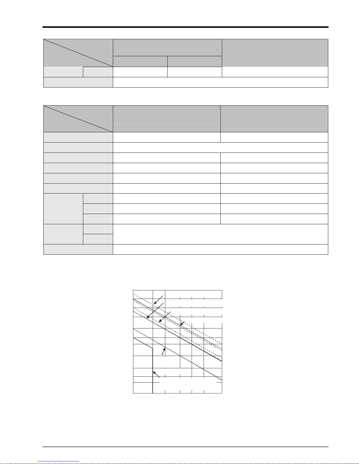
#1: Y0 ~ Y7 on DVP20PM00D are relay output; FP2+, FP2- on DVP20PM00M are high-speed transistor output, Y2 and Y3 are
low-speed transistor output, Y4 ~ Y7 are relay output. Common point for Y0: C0; common point for Y1: C1; common point for Y2
and Y3: C2; common point for Y4~Y7: C3. Output points of DVP10PM are all high-speed transistor outputs, and Y0~Y3 can be
used as general output points.
#2: The life cycle curve:
Contact
Current(A)
20
0.
5
0.
1
0.
2
30
50
0.3 0.7
12
200
300
500
100
1000
2000
3000
O
p
e
r
a
t
i
o
n
(
X
1
0
)
3
120VAC Resistive
30VDC Inductive(t=7ms)
240VAC Inductive(cos 0.4)
ψ
=
120VAC Inductive(cos =0.4)
ψ
100~200VDC
Inductive (t=7~40ms)
30VDC
Inductive
( t=40m s )
Page 21

2 Hardware Specifications and Wiring
DVP-PM Application Manual
2-6
2.1.3 Dimension
174
164
80
82.2
90
(Unit: mm)
Product Profile & Outline:
1 Communication port cover
2 I/O terminal cover
3 Function card cover
4 Input indicator
5 Output indicator
6 I/O terminal No.
7 I/O terminals
8 I/O module connection port cover
9 DIN rail clip
10 DIN rail (35mm)
11 COM2 (RS-485)
12 MANU/AUTO (STOP/RUN) switch
13 COM1 (RS-232)
14 Battery socket
15 Battery
16 Function card port
17 Function card fixing hole
18 POWER/ERROR/BAT.LOW indicators
19 I/O module connection port
20 Case fixing screw
10
2
3
1
7
6
5
9
4
8
20
12
13
11
16
17
15
19
14
18
21
21 Direct mounting hole
Page 22

2 Hardware Specifications and Wiring
DVP-PM Application Manual
2-7
COM1 cover Left-side port cover
Ports under left-side port cover Screw driver is required for removing RS-485 terminal
Battery
COM 1 (RS-232)
MANU / AUTO switch
COM 2 (RS-485)
Removable Terminal Block
Part Description
COM2 (RS-485) For both master and slave modes
MANU/AUTO (STOP/RUN) switch RUN/STOP control
COM1 (RS-232) Slave mode (can be used with COM2 at the same time)
Battery The battery shall be changed within 1 minute
Wiring Terminals: See 2.1.2 for detailed electrical specifications
START0
24G
DOG0 LSN0 PG0+ START1 DOG1 LSN1 PG1+ S/S2 X1 X3 X5 X7
+24V S/S0 STOP0 LSP0 PG0- S/S1 STOP1 LSP1 PG1- X0 X2 X4 X6
B1- CLR0- CLR1- FP0- RP0-
FP1-
RP1- C0 C1 C2 C3 Y5 Y7
CLR0+ CLR1+ FP0+ RP0+ FP1+ RP1+ Y0 Y1 Y2 Y3 Y4 Y6A0+ B0+ A1+ B1+
A1-B0-
A0-
DVP-20PM00D
( AC Po we r IN, DC Signal IN )
START0
24G
DOG0 LSN0 PG0+ START1 DOG1 LSN1 PG1+ S/S2 X1 X3 X5 X7
+24V S/S0 STOP0 LSP0 PG0- S/S1 STOP1 LSP1 PG1- X0 X2 X4 X6
B1- CLR0- CLR1- FP0- RP0- FP1- RP1- FP2- RP2- C2 C3 Y5 Y7
CLR0+ CLR1+ FP0+ RP0+ FP1+ RP1+ FP2+ RP2+ Y2
Y3
Y4 Y6A0+ B0+ A1+ B1+
A1-B0-
A0-
DVP-20PM00M
( AC Po we r IN, DC Signal IN )
Page 23

2 Hardware Specifications and Wiring
DVP-PM Application Manual
2-8
S/S
24G
X1 X3
X5
X7
X10-
X11-
X12- X13- X1 X3 X5 X7
+24V
X0
X2
X4 X6
X10+
X11+ X12+ X13+ X2 X4 X6
C3 Y10- Y11- Y12- Y13- Y14- Y15- Y16- Y17- C3 Y5 Y7
Y10+
Y11+
Y12+ Y13+ Y14+ Y15+ Y16+ Y17+ Y4 Y6Y0 Y1 Y2 Y3
C2C1
C0
DVP-10PM
( AC Power IN, DC Signal IN )
2.2 Installation & Wiring
DVP-PM is an OPEN-TYPE device and therefore should be installed in an enclosure free of airborne dust, humidity,
electric shock and vibration. The enclosure should prevent non-maintenance staff from operating the device (e.g. key
or specific tools are required for opening the enclosure) in case danger and damage on the device may occur.
DO NOT connect AC power input to any of the I/O terminals; otherwise serious damage may occur. Check all the
wiring again before switching on the power. To prevent electromagnetic interferences, make sure the PLC is properly
grounded by ground terminal
.
2.2.1 Mounting and Wiring Notes
Please install DVP-PM in an enclosure with sufficient space around it to
allow heat dissipation, as shown in the figure.
Direct Mounting:
Please use M4 screw according to the dimension of the product.
DVP MPU
> 50 mm> 50 mm
> 50 mm
> 50 mm
DIN-rail Mounting:
DVP-PM can be secured to a cabinet by using the 35mm DIN rail. When
mounting the PLC to 35mm DIN rail, be sure to use the retaining clip to stop
any side-to-side movement of the PLC and reduce the chance of wires
being loose. The retaining clip is at the bottom of the PLC. To secure the
PLC to DIN rail, pull down the clip, place it onto the rail and gently push it up.
To remove the PLC, pull the retaining clip down with a flat screwdriver and
gently remove the PLC from DIN rail.
Wiring notes:
To suit M3.5 screw terminals
Below 6.2
Below 6.2
1. Use O-type or Y-type terminals. See the figure in the left hand side for
its specification. PLC terminal screws should be tightened to 9.50
kg-cm (8.25 in-Ibs). Use 60/75ºC copper conductor only.
2. DO NOT wire empty terminal. DO NOT place the input signal cable
and output power cable in the same wire duct.
3. DO NOT drop tiny metallic conductor into the PLC while screwing and
wiring. Please attach the dustproof sticker to the PLC before the
installation to prevent conductive objects from dropping in. Tear off the
sticker before running the PLC to ensure normal heat dissipation.
Page 24

2 Hardware Specifications and Wiring
DVP-PM Application Manual
2-9
2.2.2 Power Input Wiring
The power input type for DVP-PM is AC input. When operating DVP-PM, please note the following points:
1. The range of the input voltage should be 100 ~ 240VAC. The power input should be connected to L and N
terminals. Please note that
wiring AC110V or AC220V to +24V output terminal or digital input points will result in
serious damage on the PLC.
2. The AC power inputs for the MPU and the digital I/O module should be ON or OFF at the same time.
3. Use wires of 1.6mm diameter (or bigger size) for the grounding of PLC.
4. The power shutdown of less than 10ms will not affect the operation of the PLC. However, power shutdown time
that is too long or the drop of power supply voltage will stop the running of the PLC, and all outputs will go “OFF”.
When the power returns to normal status, the PLC will automatically resume operation. (Care should be taken on
the latched auxiliary relays and registers inside the PLC when programming.).
5. The +24V output is rated at 0.5A from MPU. DO NOT connect other external power supplies to this terminal.
Every input terminal requires 5 ~ 7mA to be driven; e.g. the 16-point input will require approximately 100mA.
Therefore, +24V terminal cannot give output to the external load that is more than 400mA.
2.2.3 Safety Wiring
In PLC control system, many devices are controlled at the same time and actions of any device could influence each
other, i.e. breakdown of any device may cause danger or even the breakdown of the entire auto-control system.
Therefore, we suggest you wire a protection circuit at the power supply input terminal. See the figure below.
c
AC power supply: 100 ~ 240VAC, 50/60Hz
d
Circuit breaker
e
Emergency stop. This button cuts off the system power supply when accidental emergency occurs.
f
Power indicator
Page 25

2 Hardware Specifications and Wiring
DVP-PM Application Manual
2-10
g
AC power supply load
h
Power supply circuit protection fuse (3A)
i
DVP-PM MPU
j
DC Power supply output: 24VDC, 500mA
2.2.4 I/O Point Wiring
1. The type of input signal is DC input and there are two types of DC input: SINK and SOURCE.
z DC Signal IN - SINK mode:
S/S
X0
Sinking
Equivalent Circuit for Input Point:
24VDC
24G
X0
S/S
+24V
SINK
+5V
Wiring Circuit:
24G
S/S
X0 X1 X2+24V
Sink Type
Page 26

2 Hardware Specifications and Wiring
DVP-PM Application Manual
2-11
z DC Signal IN - SOURCE mode:
S/S
X0
Sourcing
Equivalent Circuit for Input Point
24VDC
24G
X0
S/S
+24V
SOURCE
+5V
Wiring Circuit:
24G
S/S
X0 X1 X2+24V
Source Type
2. Wiring of Differential Input:
A0 ~ A1 and B0 ~ B1 of DVP-PM series are all DC5V ~ 24V high-speed input circuit and others are DC24V
input. The working frequency of high-speed input circuit can reach up to 200kHz and is applied mainly for
connecting to output circuit with dual differential line driver.
Wiring in a high-speed, high-noise environment
Page 27

2 Hardware Specifications and Wiring
DVP-PM Application Manual
2-12
DVP20PM00D high-speed input
A
A+
A -
B -
B+
A0+
A0 -
B0+
B0 -
B
Encoder output
Differential output
Twi sted pair
cable
Encoder output
DVP10PM high-speed input
Twisted pair
cable
A
A+
A -
B -
B+
X10+
X10 -
X11+
X11 -
B
In low-noise and low-frequency (less than 50kHz) environment, you can also use single-ended DC 5V ~ 24V
SINK/SOURCE input. See below for the input wirings:
y Wiring of DVP-PM DC5V SINK
(5V SINK)
NPN
SENSOR
+
5~24V
PG0+
PG0 -
DVP-20PM
(5V SINK)
NPN
SENSOR
+
5~24V
PG0+
PG0 -
DVP-10PM
Page 28

2 Hardware Specifications and Wiring
DVP-PM Application Manual
2-13
y Wiring of DVP-PM DC5V SOURCE
(5V SOURCE)
+
5~24V
PNP
SENSOR
PG0+
PG0 -
DVP-20PM
(5V SOURCE)
+
5~24V
PNP
SENSOR
PG0+
PG0 -
DVP-10PM
3. Wiring of Relay (R) Output Circuit
c DC power supply d Emergency stop: Uses external switch
e Fuse: Uses 5 ~ 10A fuse at the shared terminal of output contacts to protect the output circuit
Page 29

2 Hardware Specifications and Wiring
DVP-PM Application Manual
2-14
f Transient voltage suppressor: To extend the life span of contact.
1. Diode suppression of DC load: Used when in smaller power.
2. Diode + Zener suppression of DC load: Used when in larger power and frequent ON/OFF
operation
g Incandescent light (resistive load) h AC power supply
i Manually exclusive output: For example, Y4 and Y5 control the forward running and reverse running
of the motor, forming an interlock for the external circuit, together with the PLC internal program, to
ensure safe protection in case of any unexpected errors.
j Neon indicator
k
Surge Absorber: To reduce the interference on AC load.
4. Wiring of Tra nsistor (T) Output Circuit
Page 30

2 Hardware Specifications and Wiring
DVP-PM Application Manual
2-15
c DC power supply d Emergency stop e Circuit protection fuse
f The transistor output model of DVP-PM applies “open collector output”. Therefore if Y0/Y1 is set as pulse
output which requires higher operation frequency, the output current passes pull-up resistor has to be
bigger than 0.1A to ensure normal operation of PLC.
1. Diode suppression: Used when in smaller power.
2. Diode + Zener suppression: Used when in larger power and frequent On/Off.
g Manually exclusive output: For example, assume that Y4 and Y5 control the forward running and reverse
running of the motor. In this case, you can design an interlock for the external circuit together with the
PLC internal program to ensure safe operation in case of any unexpected errors.
Page 31

2 Hardware Specifications and Wiring
DVP-PM Application Manual
2-16
5. Wiring of Differential Output
Wiring of DVP-PM differential output with ASDA-A, ASDA-A+ or ASDA-A2 series servo drive
/PLS
PLS
/SIGN
SIGN
FP
RP
Photocoupler
Circuit
FP+
FP-
RP+
RP-
FG0
Photocoupler
Circuit
43
41
36
37
DVP-20PM differential output
Drive
Twi s te d pa ir
cable
/PLS
PLS
/SIGN
SIGN
FP
RP
Photocoupler
circuit
Y10+
Y10-
Y11+
Y11-
FG0
Photocoupler
circuit
43
41
36
37
Drive
Twisted pair
cable
DVP-10PM differential output
Wiring of DVP-PM differential output with ASDA-B series servo drive
/PLS
PLS
/SIGN
SIGN
FP
RP
FP+
FP-
RP+
RP-
FG0
21
22
19
20
Photocoupler
circuit
Photocoupler
circuit
DVP-20PM differential output
Drive
Twisted pair
cable
/PLS
PLS
/SIGN
SIGN
FP
RP
Y10+
Y10-
Y11+
Y11-
FG0
21
22
19
20
Photocoupler
circuit
Photocoupler
circuit
Drive
Twisted pair
cable
DVP-10PM differential output
Page 32

2 Hardware Specifications and Wiring
DVP-PM Application Manual
2-17
Wiring of DVP-PM differential output with ASDA-AB series servo drive
PLS
/PLS
SIGN
/SIGN
FP
RP
DVP-20PM differential output
FP+
FP-
RP+
RP-
FG0
43
41
36
37
Photocoupler
circuit
Photocoupler
circuit
Drive
Twisted pair
cable
PLS
/PLS
SIGN
/SIGN
FP
RP
DVP-10PM differential output
Y10+
Y10-
Y11+
Y11-
FG0
43
41
36
37
Photocoupler
circuit
Photocoupler
circuit
Drive
Twisted pair
cable
Page 33

2 Hardware Specifications and Wiring
DVP-PM Application Manual
2-18
2.2.5 Wiring with Drives
Wiring of DVP-20PM with Delta ASDA-A series servo drive:
LSP0
LSN0
FP 0+
FP 0-
RP 0+
RP 0-
CLR0+
CLR0-
A0+
A0-
B0+
/PLS
B0-
+24V
24V
0V
5-24VDC
/SIGN
SIGN
VDD
COM+
24V
PLS
5-24VDC
DI2
COM-
SIGN
COM-
VDD
COM+
24V24V24V
DI2
5-24VDC
PLS
/PLS
/SIGN
+24V
PG 0+
5-24VDC
LSP1
LSN1
A1+
A1-
B1+
B1-
PG 1+
PG 0 PG 0 -
PG 1-
FP 1+
FP 1-
RP 1+
RP 1-
CLR1+
CLR1-
START1
START0
STOP1
STOP0
SIGN
VDD
COM+
24V24V24V
PLS
/PLS
/SIGN
FP 2+
FP 2-
RP 2+
RP 2-
DOG0
S/S0
DOG1
S/S1
COM-
DI2
5-24VDC
CLR2+ (Y2)
CLR2- (C2)
5-24VDC
S/S2
X3 (PG 2-)
43
36
37
41
43
36
37
41
43
36
37
41
ASDA-A series
ASDA-A series
+24V
DOG2 (X0)
S/S2
LSP2 (X2)
LSN2 (X1)
Delta servo drive
ASDA-A series
Delta servo drive
Delta servo drive
A-phase
B-phase
MPG pulses
Shielded cable
MPG pulses
Shielded cable
A-phase
B-phase
Page 34

2 Hardware Specifications and Wiring
DVP-PM Application Manual
2-19
Wiring of DVP-10PM with Delta ASDA-A series servo drive:
X4
X6
Y10+
Y10-
Y11+
Y11-
Y0
C0
Shielded cable
MPG pulses
A pha se
X10+
X10-
X11+
/PLS
B phase
X11-
D
A
B
+24V
24V
0V
Delta servo drive
A
/SIGN
SIGN
VDD
COM+
24V
B
PLS
24VDC
DI2
COM-
Delta servo drive
SIGN
COM-
VDD
COM+
24V24V24V
DI2
24VDC
PLS
/PLS
/SIGN
Y12+
Y12-
Y13+
Y13-
Y1
C1
X0
X2
ASDA-A series
Delta servo drive
SIGN
VDD
COM+
24V24V24V
PLS
/PLS
/SIGN
Y14+
Y14-
Y15+
Y15-
S/S
COM-
DI2
5-24VDC
Y2
(CLR2)
C2
43
36
37
41
43
36
37
41
43
36
37
41
ASDA-A series
ASDA-A series
Delta servo drive
SIGN
VDD
COM+
24V24V24V
PLS
/PLS
/SIGN
Y16+
Y16-
Y17+
Y17-
COM-
DI2
5-24VDC
Y3
(CLR3)
C3
43
36
37
41
ASDA-A series
S/S
24VDC
S/S
X1
X3
S/S
X5
S/S
X7
24VDC
24VDC
24VDC
Page 35

2 Hardware Specifications and Wiring
DVP-PM Application Manual
2-20
Wiring of DVP-20PM with Panasonic CN5 series servo drive:
LSP0
LSN0
FP 0+
FP 0-
RP 0+
RP 0-
CLR0+
CLR0-
A0+
A0-
B0+
B0-
+24V
24V
0V
5-24VDC
SIGN1
SIGN2
PULS1
5-24VDC
+24V
PG 0+
5-24VDC
LSP1
LSN1
A1+
A1-
B1+
B1-
PG 1+
PG 0 PG 0 -
PG 1-
FP 1+
FP 1-
RP 1+
RP 1-
CLR1+
CLR1-
START1
START0
STOP1
STOP0
PULS2
3
4
5
6
5-24VDC
SIGN1
SIGN2
PULS1
PULS2
3
4
5
6
SIGN1
SIGN2
PULS1
PULS2
3
4
5
6
SIGN1
SIGN2
PULS1
PULS2
3
4
5
6
S/S2
X3 (PG 2-)
FP 2+
FP 2-
RP 2+
RP 2-
SIGN1
SIGN2
PULS1
PULS2
3
4
5
6
SIGN1
SIGN2
PULS1
PULS2
3
4
5
6
5-24VDC
5-24VDC
CLR2+ (Y 2)
CLR2- (C2)
7
13
30
7
13
30
DC24V
GND +24V
SIGN2SIGN2
GND
COM+
GND
COM+
CLCL
+24V
DOG2 (X0)
S/S2
LSP2 (X2)
LSN2 (X1)
DOG1
S/S1
DOG0
S/S0
Panasonic servo driv
e
C5 seriesN
Panasonic servo drive
C5 seriesN
Panasonic servo drive
C5 seriesN
A-phase
B-phase
A-phase
B-phase
MPG pulses
MPG pulses
Shielded cable
Shielded cable
Page 36

2 Hardware Specifications and Wiring
DVP-PM Application Manual
2-21
Wiring of DVP-10PM with Panasonic CN5 series servo drive:
X4
X6
Y10+
Y10-
Y11+
Y11-
Y0
C0
Shielded cable
MPG pulses
A -ha se
X10+
X10-
X11+
PULS1
B-phase
X11-
+24V
24V
0V
SIGN1
SIGN2
Y12+
Y12-
Y13+
Y13-
Y1
C1
X0
X2
Y14+
Y14-
Y15+
Y15-
S/S
Y2
(CLR2)
C2
3
5
6
4
Y16+
Y16-
Y17+
Y17-
Y3
(CLR3)
C3
S/S
24VDC
S/S
X1
X3
S/S
X5
S/S
X7
24VDC
24VDC
24VDC
Panasonic servo drive
CN5
series
PULS2
PULS1
SIGN1
SIGN2
3
5
6
4
Panasonic servo drive
CN5
series
PULS2
PULS1
SIGN1
SIGN2
3
5
6
4
Panasonic servo drive
CN5 se ries
PULS2
PULS1
SIGN1
SIGN2
3
5
6
4
Panasonic servo drive
CN5 se ries
PULS2
5-24VDC
7
13
30
7
13
30
DC24V
GND +24V
GND
COM+
GND
COM+
CLCL
Page 37

2 Hardware Specifications and Wiring
DVP-PM Application Manual
2-22
Wiring of DVP-20PM with Yaskawa servo drive:
LSP0
LSN0
FP 0+
FP 0-
RP 0+
RP 0-
CLR0+
CLR0-
A0+
A0-
B0+
B0-
+24V
24V
0V
5-24VDC
SIGN
/SIGN
PULS
+24V
PG 0+
5-24VDC
LSP1
LSN1
A1+
A1-
B1+
B1-
PG 1+
PG 0 PG 0 -
PG 1-
FP 1+
FP 1-
RP 1+
RP 1-
CLR1+
CLR1-
START1
START0
STOP1
STOP0
/PULS
8
11
12
5-24VDC
7
CLR
/CLR
15
14
SIGN
/SIGN
PULS
/PULS
8
11
12
7
CLR
/CLR
15
14
5-24VDC
5-24VDC
S/S2
X3 (PG 2-)
FP 2+
FP 2-
RP 2+
RP 2-
SIGN
/SIGN
PULS
/PULS
8
11
12
7
CLR2+ (Y2)
CLR2- (C2)
CLR
/CLR
15
14
24VDC24VDC24VDC
+-
+24V
DOG2 (X0)
S/S2
LSP2 (X2)
LSN2 (X1)
DOG1
S/S1
DOG0
S/S0
Yaskawa servo drive
Yaskawa servo drive
Yaskawa servo drive
A-phase
B-phase
A-phase
B-phase
MPG pulses
MPG pulses
Shielded cable
Shielded cable
Page 38

2 Hardware Specifications and Wiring
DVP-PM Application Manual
2-23
Wiring of DVP-10PM with Yaskawa servo drive:
X4
X6
Y10+
Y10-
Y11+
Y11-
Y0
C0
Shielded cable
MPG pulses
A-phase
X10+
X10-
X11+
PLS
B-phase
X11-
+24V
24V
0V
SIGN
/SIGN
/PLS
24VDC
CLR
/CLR
Y12+
Y12-
Y13+
Y13-
Y1
C1
X0
X2
Y14+
Y14-
Y15+
Y15-
S/S
Y2
(CLR2)
C2
7
11
12
8
Y16+
Y16-
Y17+
Y17-
Y3
(CLR3)
C3
S/S
24VDC
S/S
X1
X3
S/S
X5
S/S
X7
24VDC
24VDC
24VDC
Yaskawa servo drive
14
15
PLS
SIGN
/SIGN
/PLS
24VDC
CLR
/CLR
7
11
12
8
Yaskawa servo drive
14
15
PLS
SIGN
/SIGN
/PLS
24VDC
CLR
/CLR
7
11
12
8
Yaskawa servo drive
14
15
PLS
SIGN
/SIGN
/PLS
CLR
/CLR
7
11
12
8
Yaskawa servo drive
14
15
24VDC24VDC24VDC
+-
Page 39

2 Hardware Specifications and Wiring
DVP-PM Application Manual
2-24
Wiring of DVP-20PM with Mitsubishi MJR2 series servo drive:
LSP0
LSN0
FP 0+
FP 0-
RP 0+
RP 0-
CLR0+
CLR0-
A0+
A0-
B0+
B0-
+24V
24V
0V
5-24VDC
NP
NG
PP
+24V
PG 0+
5-24VDC
LSP1
LSN1
A1+
A1-
B1+
B1-
PG 1+
PG 0 PG 0 -
PG 1-
FP 1+
FP 1-
RP 1+
RP 1-
CLR1+
CLR1-
START1
START0
STOP1
STOP0
PG
13
2
12
5-24VDC
3
CRSG8
10
5-24VDC
NP
NG
PP
PG
13
2
12
3
CRSG8
10
5-24VDC
S/S2
X3 (PG 2-)
FP 2+
FP 2-
RP 2+
RP 2-
NP
PP
PG
13
2
12
3
NG
5-24VDC
CLR2+ (Y2)
CLR2- (C2)
20
46
41
20
46
41
DC24V
GND +24V
DOCOM
DICOM
DOCOM
DICOM
CRCR
+24V
DOG2 (X0)
S/S2
LSP2 (X2)
LSN2 (X1)
DOG1
S/S1
DOG0
S/S0
Mitsubishi servo driv
e
MJR2 series
Mitsubishi servo drive
MJR2 series
Mitsubishi servo drive
MJR2 series
A-phase
B-phase
A-phase
B-phase
MPG pulses
MPG pulses
Shielded cable
Shielded cable
Page 40

2 Hardware Specifications and Wiring
DVP-PM Application Manual
2-25
Wiring of DVP-10PM with Mitsubishi MJR2 series servo drive:
X4
X6
Y10+
Y10-
Y11+
Y11-
Y0
C0
Shielded cable
MPG pulses
A-phase
X10+
X10-
X11+
PP
X11-
+24V
24V
0V
NP
NG
B-phase
PG
24VDC
CR
SG
Y12+
Y12-
Y13+
Y13-
Y1
C1
X0
X2
Y14+
Y14-
Y15+
Y15-
S/S
Y2
(CLR2)
C2
3
2
12
13
Y16+
Y16-
Y17+
Y17-
Y3
(CLR3)
C3
S/S
24VDC
S/S
X1
X3
S/S
X5
S/S
X7
24VDC
24VDC
24VDC
10
8
Mitsubishi servo drive
MITSUBISHI
MJR2 series
PP
NP
NG
PG
24VDC
CR
SG
3
2
12
13
10
8
Mitsubishi servo drive
MITSUBISHI
MJR2 series
PP
NP
NG
PG
24VDC
CR
SG
3
2
12
13
10
8
Mitsubishi servo drive
MITSUBISHI
MJR2 series
PP
NP
NG
PG
3
2
12
13
Mitsubishi servo drive
MITSUBISHI
MJR2 series
20
46
41
20
46
41
DC24V
GND +2 4V
DOCOM
DICOM
DOCOM
DICOM
CRCR
5-24VDC
Page 41

2 Hardware Specifications and Wiring
DVP-PM Application Manual
2-26
Wiring of DVP-20PM with FUJI servo drive:
LSP0
LSN0
FP 0+
FP 0-
RP 0+
RP 0-
CLR0+
CLR0-
A0+
A0-
B0+
B0-
+24V
24V
0V
5-24VDC
CB
*CB
CA
5-24VDC
+24V
PG 0+
5-24VDC
LSP1
LSN1
A1+
A1-
B1+
B1-
PG 1+
PG 0 PG 0 -
PG 1-
FP 1+
FP 1-
RP 1+
RP 1-
CLR2+ (Y 2)
CLR2- (C2)
START1
START0
STOP1
STOP0
35
36
33
34
5-24VDC
*CA
CB
*CB
CA
35
36
33
34
*CA
FP 2+
FP 2-
RP 2+
RP 2-
CB
*CB
CA
35
36
33
34
*CA
5-24VDC
S/S2
X3 (PG 2-)
5-24VDC
CL R1+
CL R1-
+24V
DOG2 (X0)
S/S2
LSP2 (X2)
LSN2 (X1)
DOG1
S/S1
DOG0
S/S0
FUJI servo drive
FUJI servo drive
FUJI servo drive
A-phase
B-phase
A-phase
B-phase
MPG pulses
MPG pulses
Shielded cable
Shielded cable
Page 42

2 Hardware Specifications and Wiring
DVP-PM Application Manual
2-27
Wiring of DVP-10PM with FUJI servo drive:
X4
X6
Y10+
Y10-
Y11+
Y11-
Y0
C0
Shielded cable
MPG pulses
A-phase
X10+
X10-
X11+
CA
B-phase
X11-
+24V
24V
0V
CB
*CB
Y12+
Y12-
Y13+
Y13-
Y1
C1
X0
X2
Y14+
Y14-
Y15+
Y15-
S/S
Y2
(CLR2)
C2
35
33
34
36
Y16+
Y16-
Y17+
Y17-
Y3
(CLR3)
C3
S/S
24VDC
S/S
X1
X3
S/S
X5
S/S
X7
24VDC
24VDC
24VDC
*CA
FUJI serv o dr ive
CA
CB
*CB
35
33
34
36
*CA
FUJI serv o dr ive
CA
CB
*CB
35
33
34
36
*CA
FUJI serv o dr ive
CA
CB
*CB
35
33
34
36
*CA
FUJI serv o dr ive
Page 43

2 Hardware Specifications and Wiring
DVP-PM Application Manual
2-28
2.3 Communication Ports
DVP-PM offers two built-in communication ports, COM1 (RS-232 communication) COM2 (RS-485 communication)
and one optional communication card, COM3 (RS-232/RS485.communication)
COM1: RS-232 communication port. Main communication port for programming. Can be used as Slave in Modbus
ASCII or RTU mode.
COM2: RS-485 communication port. Can be used as Slave / Master in Modbus ASCII or RTU mode.
COM3: RS-232/RS-485
communication port. Can be used as Slave in Modbus ASCII mode.
Communication Format:
COM port
Parameter
RS-232
(COM1)
RS-485
(COM2)
RS-232/RS-485
(COM3)
Baud rate 110~115,200 bps 110~38,400 bps
Data length 7~8bits
Parity Even/Odd/None parity check
Length of stop bit 1~2 bits
Register for Setting D1036 D1120 D1109
ASCII mode Available for Slave
Available for
Master/Slave
Available for Slave
RTU mode Available for Slave
Available for
Master/Slave
-
Data length for access
(ASCII)
100 registers 32 registers
Data length for access
(RTU)
100 registers 32 registers
Default communication settings:
− Modbus ASCII
− 7 bits
− 1 stop bit
− EVEN parity
− Baud rate: 9600bps
2.3.1 COM1 (RS-232)
1. COM1 supports RS-232 data transmission which uploads and downloads PLC program. The communication
format is Modbus (ASCII/RTU mode) and the baud rate is 9,600 ~ 115, 200bps.
Communication cable(DVPACAB2A30):
Page 44

2 Hardware Specifications and Wiring
DVP-PM Application Manual
2-29
To PC
1
5
6
9
9 Pin D-SUB
To DV P-P M
Mini DIN Terminal
PC/TP COM Port
9 Pin D-SUB female
DVP-PM COM1
8 Pin Mini DIN
Rx 2
GND 5
12
3
4
5
6
7
8
4 Rx
8 G ND
1,2 5V
1
4
6
7
8
Tx 3
5 Tx
(For detailed model names or specifications of accessories, please see the catalog of Delta PLCs or
download the latest product information from Delta's website.)
2. COM1 is used for Slave mode. Therefore, it can be connected to a HMI for monitoring purposes.
2.3.2 COM2 (RS-485)
1. COM2 supports RS-485 communication which can be used on connecting Master with multiple Slaves. The
communication format is Modbus (ASCII / RTU) and the baud rate is 9,600 ~ 115, 200bps.
2. COM2 can work in Master or Slave mode. In Master mode, it can be connected to lower position machines
such as Delta PLCs or motor drives (e.g. Delta servo drive, temperature controller, AC motor drive, and so on)
for accessing data. In Slave mode, it can be connected to HMI (e.g. Delta’s TP and DOP series HMI) for
monitoring purposes.
2.3.3 COM3 (RS-232/RS-485)
1. When the built-in COM ports, COM1 (RS-232) and COM2 (RS-485), can not fulfill the communication
requirements, users can apply additional communication cards (DVP-F232S, DVP-F485S) as COM3. The
common functions of the additional RS-232/RS-485 communication card are the same as COM1, however,
the baud rate for COM3 only supports 9600/19200/38400 bps in ASCII mode.
2. COM3 can only be used as Slave, therefore it can be connected with HMI (Human Machine Interface) for
monitoring purpose.
Page 45

2 Hardware Specifications and Wiring
DVP-PM Application Manual
2-30
MEMO
Page 46

3 Functions of Devices in DVP-PM
DVP-PM Application Manual
3-1
3.1 Devices in DVP-PM
Function Specifications:
Specifications
20PM 10PM
Note
Control system
2-axis synchronous linear/arc
interpolation and independent 2-axis
control (*5)
4-axis synchronous interpolation
and 4-axis independent control
Program storage Built-in 64k steps storage device
Control units Motor system (pulse)
Combined
system(pulse/length)
Machine system
(length)
Access method for I/O module
Access CR (Control register) of the I/O module by FROM/TO instructions.
System uses 2 CRs for 32-bit data.
Serial connection with MPU
When used as an I/O module, MPU accesses the built-in CR0 ~ CR199 (maps
to D1500 ~ D1699) of DVP-PM
Pulse output system Differential output in 3 modes: Pulse/Dir, FP(CW) / RP(CCW), A/B phase
Maximum speed For single axis: 500K PPS. For interpolation axis: 500K PPS
Operation switch
AUTO/MANU (auto/manual switch),
START, STOP
STOP/RUN (auto/manual switch)
Detector
DOG, LSP (positive limit), LSN (negative
limit), PG0 (zero point)
X0, X2, X4, X6 (DOG signal)
X1, X3, X5, X7 (Zero point signal)
Input signal
General input
point
X0 ~ X7, expandable up to 256 points (MPU + I/O module)
Servo output
FP (forward pulse), RP (reverse pulse),
CLR (clear signal)
Y10+, Y10-, Y12+, Y12-, Y14+,
Y14-, Y16+, Y16- (forward pulse)
Y11+, Y11-, Y13+, Y13-, Y15+,
Y15-, Y17+, Y17- (reverse pulse)
General output
point
Y0 ~ Y7, expandable up to 256 points (MPU + I/O module)
Output signal
COM port
COM1: RS-232 (Slave only); COM2: RS-485 (can be Master or Slave)
COM3: Optional RS-232 / RS-485 communication card (Slave only)
Special I/O
module
Optional
Shares all right-side modules with DVP-EH2 including AD, DA, PT, TC, XA,
PU, etc (maximum 8 modules expandable).
The left side of MPU can connect to high-speed I/O modules (maximum 8
modules extendable).
Extended
modules will
not occupy
any digital I/O
points.
Basic instruction 27 27
Application instruction 130 130
Motion instruction 22
M -Code
z M02: End of OX0 ~ 99 motion subroutine
z M00 ~ M01, M03 ~ M101, M103 ~ M65535: used as pause of the program,
can be applied acccroding to actual needs.
z M102: End of O100 main program
G-Code
G0 (hi-speed positioning), G1 (linear
interpolation), G2 (clockwise arc
interpolation), G3 (counter-clockwise arc
interpolation), G4 (pause), G17(X-Y
plane), G18(X-Z plane), G19(YZ plane),
G90 (absolute positioning), G91 (relative
positioning)
N/A
Self-diagnosis Displaying errors such as parameter error, program error and external errors
Page 47

3 Functions of Devices in DVP-PM
DVP-PM Application Manual
3-2
X External inputs
X0 ~ X377, octal number system, 256 points
(corresponding to physical input points)
Y External outputs
Y0 ~ Y377, octal number system, 256 points
(corresponding to physical output points)
Total 512 points
M0 ~ M499, 500 points (*2)
General
M3000 ~ M4095, 1,096 points (*3)
Latched M500 ~ M999, 500 points (*3)
M
Auxiliary
relay
Special M1000 ~ M2999, 2,000 points (some are latched)
Total 4,096
points. Can be
driven
(ON/OFF) in
program.
T Timer 10ms T0 ~ T255, 256 points (*2)
Total 256
points. The
associated
contact = ON
when timer
reaches preset
value.
C0 ~ C99, 100 points (*2) C0 ~ C99, 100 points (*2)
16-bit
count up
C100 ~ C199, 100 points (*3) C100 ~ C199, 100 points (*3)
C208 ~ C219, 12 points (*2) C208 ~ C219, 12 points (*2)
32-bit
count
up/down
C220 ~ C255, 36 points (*3) C220 ~ C255, 36 points (*3)
C Counter
32-bit
high
speed
C200, C204, 2 points (*2)
C200, C204, C208, C212, C216,
C220, 6 points
Total 250
points. The
associated
contact = ON
when counter
reaches preset
value
General S0 ~ S499, 500 points (*2)
Relay (bit)
S Step point
Latched S500 ~ S1023, 524 points (*3)
Total 1,024
points. Can be
driven
(ON/OFF) in
program.
T
Current value
T0 ~ T255, 16-bit timer. 256 words
The associated
contact = ON
when timer
reaches preset
value.
C0 ~ C199, 16-bit counter, 200 words
C
Current value
C200 ~ C255, 32-bit counter, 56 words
The associated
contact = ON
when counter
reaches preset
value.
General D0 ~ D199, 200 words (*2)
D200 ~ D999, 800 words (*3)
Latched
D3000 ~ D9999, 7,000 words (*3)
Special D1000 ~ D2999, 2,000 words (some are latched)
Register (word)
D
Data
register
Index V0 ~ V7 (16-bit), Z0 ~ Z7, 16 words (32-bit) (*1)
Total 10,000
words. General
storage for
word data. V/Z
can be used for
indirect
designation.
Pointer
P
For CJ, CJN, CALL,
JMP instructions
P0 ~ P255, 256 points
Position
pointer of CJ,
CJN, CALL
and JMP
K-32,768 ~ K32,767 (16-bit operation)
Cons
tant
K Decimal
K-2,147,483,648 ~ K2,147,483,647 (32-bit operation)
Page 48

3 Functions of Devices in DVP-PM
DVP-PM Application Manual
3-3
H Hex
H0000 ~ HFFFF (16-bit operation); H00000000 ~ HFFFFFFFF (32-bit
operation)
F Floating point
Displaying floating point value by 32-bit data complying with IEEE754
standard.
±1.1755X10
-38
~ ±3.4028X10
+38
*1: Non-latched area cannot be modified.
*2: Non-latched area, can be modified as latched area by changing the parameter settings
*3: Latched area, can be modified as non-latched area by changing the parameter settings
*4: Latched area, cannot be modified
*5: DVP20PM00M supports 3-axis linear interpolation and helical interpolation
Settings of latched and non-latched memory devices:
*1: If you set D1200 = 0 and D1201 = 4095, DVP-PM will automatically ignore M1000 ~ M2999 and set M0 ~ M999 and M3000 ~
M4095 as latched area.
*2: K-1 refers to default = not latched.
*3: If you set D1210 = 0 and D1211 = 9999, DVP-PM will automatically ignore D1000 ~ D2999 and set D0 ~ D999 and D3000 ~
D9999 as latched areas.
General purpose Special auxiliary relay
M0 ~ M499 M500 ~ M999 M3000 ~ M4095 M1000 ~ M2999
Default:: not latched Default:: latched Default:: not latched
Allocated in the range of “general
purpose” M relays
M
(Auxiliary relay)
Start:: D1200 (K500)*1
End: D1201 (K999) *1
Some are latched and cannot be
modified.
10ms
T0 ~ T255
Default:: not latched
T
(Timer)
Start:: D1202 (K-1) *2
End: D1203 (K-1) *2
16-bit count up 32-bit count up/down
C0 ~ C99 C100 ~ C199
C200, C204
C208 ~ C219
C220 ~ C255
Default:: not latched Default:: latched Default:: not latched Default:: latched
C
(Counter)
Start:: D1204 (K100)
End: D1205 (K199)
Start:: D1206 (K220)
End: D1207 (K255)
Initial General purpose Latched
S0 ~ S9 S10 ~ S499 S500 ~ S1023
Default:: non-latched Default:: latched
S
(Step relay)
Start:: D1208 (K500), End: D1209 (K1023)
General purpose Latched Special register
D0 ~ D999 D3000 ~ D9999
D1000 ~ D2999
Allocated in the range of "general
purpose” registers
Default:: not latched Default:: latched
D
(Register)
Start:: D1210 (K200) *3
End: D1211 (K9999) *3
Some are latched and cannot be
modified.
Page 49

3 Functions of Devices in DVP-PM
DVP-PM Application Manual
3-4
Memory status between ON/OFF operation
Memory type
Power
OFF->ON
MANU->AUTO
(STOP->RUN)
AUTO->MANU
(RUN->STOP)
Clear all non-latched
areas (M1031=ON)
Clear all latched area
(M1032=ON)
Default
Cleared when
M1033 = OFF
Non-latched Cleared Unchanged
Unchanged when
M1033 = ON
Cleared Unchanged 0
Latched Unchanged Unchanged Cleared 0
3.2 Values, Constants [K] / [H], Floating Points [F]
K
Decimal
K-32,768 ~ K32,767 (16-bit operation)
K-2,147,483,648 ~ K2,147,483,647 (32-bit operation)
Constant
H Hexadecimal form
H0000 ~ HFFFF (16-bit operation)
H00000000 ~ HFFFFFFFF (32-bit operation)
Floating
point
F 32 bits
Displaying floating point value by 32-bit data complying with IEEE754 standard.
±1.1755X10
-38
~ ±3.4028X10
+38
For fulllfilling different kinds of internal manipulation, DVP-PLC appies 5 foramts of number systems. Each number
system has its specific purpose and function described as below.
1. Binary value (BIN)
DVP-PM internally calculates, operates, and stores the value in Binary format.
Bit
Bit is the basic unit of a binary number system. Range is 0 or 1
Nibble
Consists of 4 consecutive bits, e.g. b3~b0. Range 0 ~ 9 in Decimal or 0~F in Hex
Byte
Consists of 2 consecutive nibbles, e.g. b7~b0. Range 00 ~ FF in Hex
Word
Consists of 2 consecutive bytes, e.g. b15~b0. Range 0000 ~ FFFF in Hex
Double Word
Consists of 2 consecutive words, e.g. b31~b1. Range 00000000 - FFFFFFFF in Hex
Bit, nibble, byte, word and double word in a binary system:
NB0NB1NB2NB3NB4NB5NB6NB7
BY3 BY2 BY1 BY0
W1
DW
W0
Double word
Word
Byte
Nibble
Bit
2. Octal value (OCT)
The external I/O points of DVP-PLC are numbered in octal format.
e.g.
External inputs: X0~X7, X10~X17, …, X377. (No. of device)
External outputs: Y0~Y7, Y10~Y17, …, Y377. (No. of device)
Page 50

3 Functions of Devices in DVP-PM
DVP-PM Application Manual
3-5
3. Decimal value (DEC)
DVP-PLC appies decimal operation in situations below:
Set value for timers and counters, e.g. TMR C0 K50. (K value)
No. of S, M, T, C, D, E, F, P, I devices, e.g. M10, T30. (No. of device)
For use of operand in API instructions, e.g. MOV K123 D0. (K value)
4. Binary coded decimal (BCD)
BCD format takes 1 digit or 4 bits to indicate a Decimal value, so that data of consecutive 16 bits indicates a
4-digit decimal value. Used mainly for reading values from DIP switches or sending data to 7-segement displays.
5. Hexadecimal value (HEX)
Occasion of using hexadecimal values:
For use of operand in API instructions, e.g. MOV H1A2B D0。(H value)
Constant K:
Decimal value in PLC operation is attached with an “K”, e.g. K100 indicates the value 100 in Decimal format.
Exception:
When constant K is used with bit devices X, Y, M or S, the value specifed after K indicates the groups
of 4-bit unit, which forms a digit(4-bit), byte(8 bit), word(16bit), or double word(32-bit) data, e.g.
K2Y10, K4M100, representing Y10 ~ Y17 and M100~M115.
Constant H:
Hexadecimal value in PLC operation is attached with an “H”, e.g. H100 indicates the value 256 in Hex format.
Floating point F:
Floating point value in PLC operation is attached with an “F”, e.g. F3.123 refers to a floating point value, 3.123. 23.
Reference table:
Binary
(BIN)
Octal
(OCT)
Decimal
(DEC)
Binary Code Decimal
(BCD)
Hexadecimal
(HEX)
For DVP-PM internal operation
No. of device X,
Y
Constant K and No.
of device M, S, T, C,
D, V, Z, P
For DIP switch and 7-segment
display
Constant H
0000 0000 0 0 0 0 0 0 0 0 0 0 0
0000 0001 1 1 0 0 0 0 0 0 0 1 1
0000 0010 2 2 0 0 0 0 0 0 1 0 2
0 0 0 0 0 0 1 1 3 3 0 0 0 0 0 0 1 1 3
0000 0100 4 4 0 0 0 0 0 1 0 0 4
0000 0101 5 5 0 0 0 0 0 1 0 1 5
0 0 0 0 0 1 1 0 6 6 0 0 0 0 0 1 1 0 6
0 0 0 0 0 1 1 1 7 7 0 0 0 0 0 1 1 1 7
0000 1000 10 8 0 0 0 0 1 0 0 0 8
0000 1001 11 9 0 0 0 0 1 0 0 1 9
0000 1010 12 10 0 0 0 1 0 0 0 0 A
0000 1011 13 11 0001 0001 B
Page 51

3 Functions of Devices in DVP-PM
DVP-PM Application Manual
3-6
Binary
(BIN)
Octal
(OCT)
Decimal
(DEC)
Binary Code Decimal
(BCD)
Hexadecimal
(HEX)
For DVP-PM internal operation
No. of device X,
Y
Constant K and No.
of device M, S, T, C,
D, V, Z, P
For DIP switch and 7-segment
display
Constant H
0000 1100 14 12 0001 0010 C
0 0 0 0 1 1 0 1 15 13 0 0 0 1 0 0 1 1 D
0 0 0 0 1 1 1 0 16 14 0 0 0 1 0 1 0 0 E
0000 1111 17 15 0 0 0 1 0 1 0 1 F
0 0 0 1 0 0 0 0 20 16 0 0 0 1 0 1 1 0 10
0001 0001 21 17 0 0 0 1 0 1 1 1 11
: : : : :
0 1 1 0 0 0 1 1 143 99 1 0 0 1 1 0 0 1 63
3.3 Numbering and Function of External Input/Output Contacts [X] / [Y]
Input relay X0 ~ X377
The numbering of input relay (or input terminal) is in octal format. DVP-PM is designed for up to 256 points, and
the range is: X0 ~ X7, X10 ~ X17, ...X370 ~ X377.
Output relay Y0 ~ Y377
The numbering of output relay (or output terminal) is in octal format. DVP-PM is designed for up to 256 points,
and the range is: Y0 ~ Y7, Y10 ~ Y17, …Y370 ~ Y377.
Function of input contact X
The input contact X is connected to input devices and reads the input signals into DVP-PM. There is no limitation
on the times of using NO (Normally Open) / NC (Normally Closed) contacts in the program. ON/OFF of the input
contact X only changes with ON/OFF status of the connected devices. PMSoft can not force ON/OFF the input
contact X.
M1304, Force ON/OFF contact X
When M1304 = OFF, input contact can not be force ON/OFF by PMSoft; when M1304 = ON, input contact X can
be force ON/OFF by PMSoft. However, the function of updating input signals will be disabled in this case.
Function of output contact Y
Output contact Y sends out ON/OFF signals to drive the load connected to output contacts. There are two types
of output contacts, relay and transistor. There is no limitation on the times of using Y contacts (NO / NC) in the
program. However, we suggest users do not repeat the No. of output coil Y; otherwise, according to the scan
principle of ladder diagram, the status of output coil will be determined by the status of the last Y in the program.
X0
X10
Y0
Y0
1
2
Y0 is repeated.
The output of Y0 will be determined by Y0 in 2, i.e. ON/OFF of X10
will determine the output status of Y0.
Page 52

3 Functions of Devices in DVP-PM
DVP-PM Application Manual
3-7
The handling process of DVP-PM program:
X0
Y0
Y0
M0
X inpu t
Update input signal
Program processing
Update output
Input terminal
Input signal memory
Read into memory
Read X0 status from memory
Write in
Y0 status
Read Y0 status from memory
Write in
M0 status
D
e
v
i
c
e
m
e
m
o
r
y
Output
Output latched memory
Output terminal
Y output
Update input signal
1. Before the execution of the program, DVP-PM reads
the ON/OFF status of the external input signals into the
input signal memory.
2. The ON/OFF status of input signal changed during
program execution will not be read into input signal
memory. The new ON/OFF status will be read in the
next scan.
3. There will be approximately a 10ms delay from external
ON/OFF switching to the internal ON/OFF of contacts.
The delay time may be affected by program scan time.
Program processing
After DVP-PM reads the ON/OFF status stored in the
input signal memory, it executes every instruction from
address 0 and stores the status of devices into the
device memory.
Update output
1. When the execution reaches M102 instruction, DVP-PM
sends the ON/OFF status of Y in the device memory to
the output latched memory. The output latched memory
is the coil of the output relay.
2. There will be a 10ms delay from the ON/OFF switching
of output relay to the actual ON/OFF of physical output
contacts.
3. For transistor output MPU, there will be a 10 ~ 20us
delay from the ON/OFF switching to the actual ON/OFF
of physical output contacts.
3.4 Numbering and Functions of Auxiliary Relays [M]
No. of auxiliary relays (in decimal):
General purpose
M0 ~ M499, 500 points, can be modified as latched area by setting up
parameters.
Latched
M500 ~ M999, M3000 ~ M4095, 1,596 points, can be modified as
non-latched area by setting up parameters.
Auxiliary relay
M
Special purpose M1000 ~ M2999, 2,000 points, some are latched.
Total 4,096
points
Functions of auxiliary relays:
Both auxiliary relay M and output relay Y have output coils and NO, NC contacts, and there is no limitation on the
times of using the contacts. You can use auxiliary relay M in the program but it cannot directly drive the external load.
There are three types of auxiliary relays.
Page 53

3 Functions of Devices in DVP-PM
DVP-PM Application Manual
3-8
1. General auxiliary relay: If the relay encounters power OFF during the operation of DVP-PM, its status will be
reset to OFF and remains OFF when the power is ON again.
2. Latched auxiliary relay: If the relay encounters power OFF during the operation of DVP-PM, its status will be
retained and resumes the status when the power is ON again.
3. Special auxiliary relay: Every relay of this kind has its specific function. DO NOT use undefined special purpose
auxiliary relay. See 3.10 for special relay and special registers and 3.11 for their functions.
3.5 Numbering and Functions of Step Relays [S]
No. of step relay (in decimal):
General purpose
S0 ~ S499, 490 points, can be modified as latched area by setting up
parameters.
Step relay
S
Latched
S500 ~ S1023, 524 points, can be modified as non-latched area by
setting up parameters.
Total 1,024
points
Functions of step relays:
The device No. of S is S0 ~ S1023 (total 1,024 points). Both step relay S and output relay Y have output coils and NO,
NC contacts, and there is no limitation on the times of using the contacts. You can use auxiliary relay M in the
program but it cannot directly drive the external load. Step relay can be used as general auxiliary relays.
3.6 Numbering and Functions of Timers [T]
No. of timers (in decimal):
Timer
T
10ms general purpose
T0 ~ T255, 256 points, can be modified as latched area by setting up
parameters.
Functions of timers:
The timer resolution is 10ms and counts up when activated. The associated contacts of timer will be driven when the
current value reaches the set value in timer. Set value can be K value (decimal) or D register.
The actual set time in the timer = timer resolution × set value
General purpose timer:
General timer counts once when TMR instruction is driven once. When TMR instruction is executed and the present
value reaches the set value, the associated output coil will be ON.
T0
Y0
X0
TMR T0 K100
X0
T0
Y0
PV
SV = K100
1 sec
When X0 = ON, The PV in timer T0 will count up with
timer resolution 10ms. When the PV = SV (K100), the
output coil T0 will be ON.
When X0 = OFF or the power is OFF, the PV in timer
T0 will be cleared as 0, and the output coil will be OFF.
Page 54

3 Functions of Devices in DVP-PM
DVP-PM Application Manual
3-9
How to designate SV: The actual set time in the timer = timer resolutiont × set value
1. Designating constant K: set a K value as SV directly
2. Designating D register: designate a data register in TMR instruction and the timer will take the value in the register
as the SV.
3.7 Numbering and Functions of Counters [C]
No. of counters (in decimal):
20PM:
16-bit count up C0 ~ C199, 200 points
32-bit count up/down C208 ~ C255, 48 points (accumulative)
Total 248 points
The associated contact = ON
when counter reaches preset
value
Counter
C
32-bit high speed C200, C204 Total 2 points
z Input point of C200:
MPGA0/MPGB0
z Input point of C204:
MPGA1/MPGB1
10PM:
16-bit count up C0 ~ C199, 200 points
32-bit count up/down C220 ~ C255, 36 points (accumulative)
Total 236 points
The associated contact = ON
when counter reaches preset
value
Counter
C
32-bit high speed
C200, C204, C208, C212, C216, C220.
6 points
Total 6 points
z Input point of C200:
X0/X1
z Input point of C204:
X2/X3
z Input point of C208:
X4/X5
z Input point of C212:
X6/X7
z Input point of C216:
X10+ / X10- / X11+ / X11-
z Input point of C220:
X12+ / X12- / X13+ / X13-
Features of counter:
16-bit counter 32-bit counter
Type General purpose General purpose
Counting direction Count up Count up, count down
Range of SV 0 ~ 32,767 -2,147,483,648 ~ +2,147,483,647
Designating SV Constant K or data register D Constant K or data register D (2 consecutive words)
Operation when SV
is reached
Counting will stop after SV is reached. Counting will continue after SV is reached.
Output contact
The associated contact = ON and latched when
counter reaches SV.
The associated contact = ON and latched when
counter reaches preset value in counting-up mode
The associated contact is reset as OFF when counter
reaches preset value in counting-down mode
Reset When RST instruction is executed, PV of counter is cleared and the contact is OFF.
Contact Action Contacts act when the scan is completed. Contacts act when the scan is completed.
Page 55

3 Functions of Devices in DVP-PM
DVP-PM Application Manual
3-10
Functions of counters:
The counters count once when CNT instruction is driven once. When CNT instruction is executed and the PV reaches
SV, the associated output coil will be ON. SV can be K value (decimal) or D register
16-bit counters C0 ~ C199:
1. The set range of 16-bit counter: K0 ~ K32,767. SV=K0 is the same as SV=K1, i.e. the associated output contact
will be ON immediately when counter is activated.
2. PV in the general purpose counter will be cleared when the power of DVP-PM is OFF. If the counter is a latched
(accumulative) type, PV and the contact status will be retained, and PLC will resume counting after the power is
ON again.
3. If you use MOV instruction or PMSoft to send a value bigger than SV to the present value register of C0, when
X1 goes from OFF to ON, the associated contact of counter C0 will be ON and its PV will equal SV.
4. SV can be K value (decimal) or D register (Special data register D1000~D2999 is not included).
5. Constant K should be a positive value for SV, however, values in data register D can be positive or negative.
When PV reaches up to 32,767, the next PV will turn to -32,768.
Example:
LD X0
RST C0
LD X1
CNT C0 K5
LD C0
OUT Y0
C0
Y0
X1
C0 K5CNT
X0
C0RST
1. When X0 = ON, RST instruction is executed, PV in C0 will be cleared and the associated contact will be reset.
2. When X1 goes from OFF to ON, PV in the counter will count up (plus 1).
3. When the counting of C0 reaches SV = K5, the contact of C0 will be ON. X1 input signal comes afterwards will
not be accepted by C0, ad PV of C0 will stay at K5.
X0
X1
Contacts Y0,C0
PV in C0
0
1
2
3
4
5
0
SV
32-bit general count-up/count-down counters: C208 ~ C255(20PM) / C220~C255(10PM)
1. The setup range of 32-bit counter: K-2,147,483,648 ~ K2,147,483,647. Counting mode (count-up/count-down) of
the counter is designated by ON/OFF status of special auxiliary relay M1208 ~ M1255. For example, when
M1255 = OFF, C255 will be a count-up counter; when M1255 = ON, C255 will be a count-down counter.
2. SV can be K value (decimal) or D register (Special data register D1000~D2999 is not included). If a D register is
Page 56

3 Functions of Devices in DVP-PM
DVP-PM Application Manual
3-11
specified as SV, it will occupy 2 consecutive data registers.
3. PV in the general purpose counter will be cleared when power of DVP-PM is OFF. If the counter is a latched
(accumulative) type, PV and the contact status will be retained, and PLC will resume counting after power is ON
again.
4. When PV reaches up to 2,147,483,647, the next PV will turn to -2,147,483,648. When PV reaches down to
-2,147,483,648, the next PV will turn to 2,147,483,647.
Example:
LD X10
OUT M1255
LD X11
RST C255
LD X12
DCNT C255 K-5
LD C255
OUT Y0
C255
Y0
X12
C255 K-5DCNT
X11
C255RST
X10
M1255
1. X10 drives M1255 to determine whether C255 is a count-up or count-down counter.
2. When X11 goes from OFF to ON, RST instruction will be executed, PV in C255 will be cleared, and the
associated contact will be reset.
3. When X12 goes from OFF to ON, PV in the counter will count up (plus 1) or down (minus 1).
4. When PV in C255 changes from K-6 to K-5 (PV≧SV), the contact of C255 will go from OFF to ON. When PV in
C255 changes from K-5 to K-6 (PV≦SV), the contact of C255 will go from ON to OFF.
5. If you use MOV instruction or PMSoft to send a value bigger than SV to the present value register of C0, when
X1 goes from OFF to ON, the associated contact of counter C0 will be ON and its PV will equal SV.
X10
X11
X12
Contacts Y0,C255
0
1
2
3
454
3
2
1
0
-1
-2
-3
-4
-5
-6
-7
-8
0
-7
-6
-5
-4
-3
Counting up Counting up
Counting down
PV in C255
Status if Y0 was ON
Page 57

3 Functions of Devices in DVP-PM
DVP-PM Application Manual
3-12
32-bit High Speed Counter:
20PM:
C200, C204
1. The setup range of 32-bit high speed counter: K-2,147,483,648 ~ K2,147,483,647.
2. C200/C204 counting mode setting:
Counting mode
Counter
Device b0 / b1
Reset signal
(Valid only when b3 = 1)
Input signal
1st set C200 K1M1200 PG0 (M1203) A0+, A0-, B0+, B0-
2nd set C204 K1M1204
0: U/D*
1: P/D*
2: A/B*
(Single frequency)
3:4A/B
(Quadruple
frequency)
X11- (M1207) X2, X3, S/S
Note:
z U/D: Counting up / Counting down, P/D: Pulse / Direction, A/B: A-phase / B-phase
3. M1908: Input signal control of C200 / C204
When M1908 = OFF, the input signal of C200 is controlled by MPG A0/B0 and reset signal is controlled by
PG0. In addition, Input signal of C204 is controlled by MPG A1/B1 and reset signal is controlled by PG1.
C200
C200
reset signal
Counting mode selection
Input pulse
Input pulse
Puls
e
U
A
B
Dir
PV of C200
D
M1200/M1201
MPGB0
MPGA0
M1203=1, PG0
C204
C204
reset signal
Counting mode selection
Input pulse
Input pulse
Puls
e
U
A
B
Dir
PV of C204
D
M1204/M1205
MPGB1
MPGA1
M1207=1, PG1
When M1908 = ON, the 3 axes X/Y/Z share the same high speed counter C200. The input signal of C200
is controlled by MPG A0/B0. C200 reset signal is controlled by PG0.
Page 58

3 Functions of Devices in DVP-PM
DVP-PM Application Manual
3-13
C200
C200
reset signal
Counting mode selection
Input pulse
Input pulse
Puls
e
U
A
B
Dir
PV of C200
D
M1200/M1201
MPGB0
MPGA0
M1203=1, PG0
4. SV can be K value (decimal) or D register (Special data register D1000~D2999 is not included). SV can be
a positive or negative value. If a D register is specified as SV, it will occupy 2 consecutive data registers.
5. PV in the general purpose counter will be cleared when power of DVP-PM is OFF. If the counter is a
latched (accumulative) type, PV and the contact status will be retained, and PLC will resume counting after
power is ON again.
6. When PV reaches up to 2,147,483,647, the next PV will turn to -2,147,483,648. When PV reaches down
to -2,147,483,648, the next PV will turn to 2,147,483,647.
10PM:
C200, C204, C208, C216, C220
1. The setup range of 32-bit high speed counter: K-2,147,483,648 ~ K2,147,483,647.
2. C200/C204/C208/C216/C220 counting mode settings:
Counting mode
Counter
Device b0 / b1
Reset signal Reset
terminal
Input signal
1st set C200 K1M1200 M1203 X10 X0, X1, S/S
2nd set C204 K1M1204 M1207 X11 X2, X3, S/S
3rd set C208 K1M1208 M1211 X12 X4, X5, S/S
4th set C212 K1M1212 M1215 X13 X6, X7, S/S
5th set C216 K1M1216 M1219 X0 X10+, X10-, X11+, X11-
6th set C220 K1M1220
0: U/D*
1: P/D*
2: A/B*
(Single
frequency)
3:4A/B
(Quadruple
frequency)
M1223 X1 X12+, X12-, X13+, X13-
Note:
z U/D: Counting up / Counting down, P/D: Pulse / Direction, A/B: A-phase / B-phase
3. Operation diagram:
z Counting mode of C200 is selected by M1200/M1201. Input signal of C200 is controlled by X0/X1.
Reset signal of C200 is enabled by M1203 and triggered by X10.
Page 59

3 Functions of Devices in DVP-PM
DVP-PM Application Manual
3-14
C200
C200
reset signal
Counting mode selection
Input pulse
Input pulse
Puls
e
U
A
B
Dir
PV of C200
D
M1200/M1201
X1
X0
M1203=1, X0+
z Counting mode of C204 is selected by M1204/M1205. Input signal of C204 is controlled by X2/X3.
Reset signal of C204 is enabled by M1207 and triggered by X11.
C204
C204
reset signal
Counting mode selection
Input pulse
Input pulse
Puls
e
U
A
B
Dir
PV of C204
D
M1205/M1204
X3
X2
M1207=1, X11-
z Counting mode of C208 is selected by M1208/M1209. Input signal of C208 is controlled by X4/X5.
Reset signal of C208 is enabled by M1211 and triggered by X12.
C208
C208
reset signal
Counting mode selection
Input pulse
Input pulse
Puls
e
U
A
B
Dir
PV of C208
D
M1209/M1208
X5
X4
M1211=1, X12-
z Counting mode of C212 is selected by M1212/M1213. Input signal of C212 is controlled by X6/X7.
Reset signal of C212 is enabled by M1215 and triggered by X13.
Page 60

3 Functions of Devices in DVP-PM
DVP-PM Application Manual
3-15
C212
C212
reset signal
Counting mode selection
Input pulse
Input pulse
Puls
e
U
A
B
Dir
PV of C212
D
M1213/M1212
X7
X6
M1215=1, X13-
z Counting mode of C216 is selected by M1216/M1217. Input signal of C216 is controlled by X10/X11.
Reset signal of C216 is enabled by M1219 and triggered by X0.
C216
C216
reset signal
Counting mode selection
Input pulse
Input pulse
Puls
e
U
A
B
Dir
PV of C216
D
M1217/M1216
X11
X10
M1219=1, X0
z Counting mode of C220 is selected by M1220/M1221. Input signal of C220 is controlled by X12/X13.
Reset signal of C220 is enabled by M1223 and triggered by X1.
C220
C220
reset signal
Counting mode selection
Input pulse
Input pulse
Puls
e
U
A
B
Dir
PV of C220
D
M1221/M1220
X13
M1223=1, X1
4. SV can be K value (decimal) or D register (Special data register D1000~D2999 is not included). SV can be
a positive or negative value. If a D register is specified as SV, it will occupy 2 consecutive data registers.
5. PV in the general purpose counter will be cleared when power of DVP-PM is OFF. If the counter is a
latched (accumulative) type, PV and the contact status will be retained, and PLC will resume counting after
power is ON again.
6. When PV reaches up to 2,147,483,647, the next PV will turn to -2,147,483,648. When PV reaches down
to -2,147,483,648, the next PV will turn to 2,147,483,647
Page 61

3 Functions of Devices in DVP-PM
DVP-PM Application Manual
3-16
3.8 Numbering and Functions of Registers [D]
3.8.1 Data Register [D]
16-bit data register stores the value between -32,768 ~ +32,767. The MSB (Most Significant Bit) is also the sign bit
indicating the value as positive “+” or negative “-“. Two 16-bit registers can be combined into a 32-bit register (D+1, D;
register with smaller number is low word) storing the value between -2,147,483,648 ~ +2,147,483,647. Also, MSB is
the sign bit.
General purpose
D0 ~ D199, 200 points, can be modified into latched area by setting up
parameters.
Latched
D200 ~ D999, D3000 ~ D9999, 7,800 points, can be modified into
non-latched area by setting up parameters.
Special purpose D1000 ~ D2999, 2,000 points, some are latched
Data register
D
Index register V, Z V0 ~ V7, Z0 ~ Z7, 16 points
Total 10,000
points
File register K0 ~ K9,999, MPU 10,000 points, fixed as latched 10,000 points
There are 4 types of registers:
1. General purpose register: When DVP-PM goes from AUTO to MANU
(STOP->RUN) or the power is switched
off, the data in the register will be cleared to “0”. When M1033 = ON and DVP-PM goes from AUTO to MANU
(STOP->RUN), the data will not be cleared but will still be cleared to “0” when the power is OFF.
2. Latched register: When the power of DVP-PM is switched off, the data in the register will not be cleared and
will retain the value before the power is OFF. You can use RST or ZRST instruction to clear the data in the
latched register.
3. Special purpose register: Every register of this kind has its special definition and purpose, mainly for storing
the system status, error messages and monitoring status. See 3.10 and 3.11 for more details.
4. Index register V, Z: V is a 16-bit register, and Z is a 32-bit register. V0 ~ V7, Z0 ~ Z7, total 16 points.
3.8.2 Index Registers [V], [Z]
V0
Z0
16 bit
s
32 bits
Register V is a 16-bit register and can be written and read as a
general data register. V as a general register can only be used in
16-bit instructions.
Z is a 32-bit register. Z as a general data register can only be used
in 32-bit instructions.
K14 Z1
X0
K8 V0
MOV
DMOV
D3@Z1 D4@V0
D0@V0 D2@Z1MOV
DMOV
When X0 = ON, V0 = 8, Z1 = 14.
D0@V0 = D8, D2@Z1 = D16
The content in D8 will be moved to D16
The content in D17 will be moved to D12
V and Z for modifying the operands can be used in both 16-bit and
32-bit instructions (as the example).
The index register can be used as normal operands for moving or comparison on word devices (KnX, KnY, KnM, KnS,
T, C, D) and bit devices (X, Y, M, S).
Page 62

3 Functions of Devices in DVP-PM
DVP-PM Application Manual
3-17
V0 ~ V7, Z0 ~ Z7, total 16 point
Constant and some instructions do not support index registers. For how to use index register V, Z to modify the
operands, see Ch5, 5.4 section for more details.
When you use index register V, Z to modify the operands, the modification range CANNOT exceed the area of
special purpose registers D1000 ~ D2999 and special auxiliary relays M1000 ~ M2999 in case errors may occur.
3.9 Pointer [N], Pointer [Pn]
N For nested level structure N0 ~ N7, 8 points Control point of nested level
Pointer
P For CJ, CJN, JMP instructions P0 ~ P255, 256 points Position pointer of CJ, CJN, JMP
Pointer P: Used with API 00 CJ, API 256 CJN, and API 257 JMP. See Chapter 5 for explanations on CJ, CJN and
JMP instructions for more details.
CJ conditional jump:
X2
Y2
X1
P1CJ
X0
Y1
P**
0
N
P1
When X0 = ON, the program will jump from address 0 to N
(Pointer P1) and keep on the execution. The instructions
between CJ instruction and P1 will be ignored.
When X0 = OFF, the program will execute from address 0 and
keep on executing. In this case, CJ instruction will not be
executed.
Page 63

3 Functions of Devices in DVP-PM
DVP-PM Application Manual
3-18
3.10 Special Auxiliary Relays [M], Special Data Register [D]
The types and functions of special auxiliary relays (special M) are listed in the table below. Special M and special D
marked with “*” will be further illustrated in 3.11. Columns marked with “R” refers to “read only”, “R/W” refers to “read
and write”, “-“ refers to the status remains unchanged and “#” refers to that system will set it up according to the status
of the PLC..
Special
M
Function 10M
20D 20M
OFF
Ø
ON
MANU
Ø
AUTO
AUTO
Ø
MANU
Attrib. Latched Default
Page
number
M1000*
Monitoring normally open contact:: ON when AUTO is
activated
○○○
OFF ON OFF R NO OFF 3-35
M1001*
Monitoring normally closed contact: OFF when AUTO is
activated
○○○
ON OFF ON R
NO
ON 3-35
M1002*
Enable single positive pulse at the moment when AUTO is
activated (Normally OFF)
. Pulse width = scan time.
○○○
OFF ON OFF R
NO
OFF 3-35
M1003*
Enable single negative pulse at the moment when AUTO is
activated (Normally ON)
. Pulse width = scan time.
○○○
ON OFF ON R
NO
ON 3-35
M1008
Watchdog timer (ON: PLC WDT time out)
○○○
OFF OFF - R
NO
OFF -
M1009 Indicate that LV status occurred.
○○○
OFF - - R
NO
OFF
M1011
10ms clock pulse, 5ms ON / 5ms OFF
○○○
OFF - - R
NO
OFF -
M1012
100ms clock pulse, 50ms ON / 50ms OFF
○○○
OFF - - R
NO
OFF -
M1013
1s clock pulse, 0.5s ON / 0.5s OFF
○○○
OFF - - R
NO
OFF -
M1014
1min clock pulse, 30s ON / 30s OFF
○○○
OFF - - R
NO
OFF -
M1025
Indicate incorrect request for communication (When PC
or HMI is connected with DVP-PM, and DVP-PM
receives illegal request for communication service during
the data transmission, M1025 will be set, and the error
code will be stored in D1025.)
○○○
OFF OFF - R
NO
OFF -
M1026 RAMP mode selection ○○○
OFF - - R/W
NO
OFF
M1029 CH0 (Y0, Y1) pulse output execution completed. ○○○
OFF - - R
NO
OFF
M1031 Clear all non-latched memory
○○○
OFF - - R/W
NO
OFF -
M1032 Clear all latched memory
○○○
OFF - - R/W
NO
OFF -
M1033 Memory latched when not in operation
○○○
OFF - - R/W
NO
OFF -
M1034 Disable all Y outputs
○○○
OFF - - R/W
NO
OFF -
M1035 Enable STOP0/START0 as external input points
○○○
OFF OFF OFF R/W
NO
OFF -
M1036*
Enable continouous interpolation on application
instructions
○○○
OFF OFF OFF R/W
NO
OFF 3-46
M1039* Fix scan time
○○○
OFF - - R/W NO OFF 3-39
M1048
Indicating alarm status
○○○
OFF - - R
NO
OFF
-
M1049
Enabling alarm monitoring
○○○
OFF - - R/W NO OFF
-
M1072
PLC status (AUTO / MANU), ON = AUTO
(communication)
○○○
OFF ON OFF R/W
NO
OFF -
M1074* Enable OX motion subroutine
╳○○
OFF - - R/W
NO
OFF 3-39
M1077 Battery in low voltage, malfunction or no battery
○○○
OFF - - R/W
NO
OFF -
M1087 Indicate current LV status
○○○
OFF - - R/W
NO
OFF -
Page 64

3 Functions of Devices in DVP-PM
DVP-PM Application Manual
3-19
Special
M
Function 10M
20D 20M
OFF
Ø
ON
MANU
Ø
AUTO
AUTO
Ø
MANU
Attrib. Latched Default
Page
number
M1120*
Retain the communication setting of COM2 (RS-485).
Modifying D1120 will be invalid when M1120 is set.
○○○
OFF OFF - R/W
NO
OFF 3-36
M1121 For COM2(RS-485), data transmission ready
○○○
OFF ON - R
NO
OFF -
M1122 For COM2(RS-485), sending request
○○○
OFF OFF - R/W
NO
OFF -
M1123 For COM2(RS-485), data receiving completed
○○○
OFF OFF - R/W
NO
OFF -
M1124 For COM2(RS-485), data receiving ready
○○○
OFF OFF - R
NO
OFF -
M1125 For COM2(RS-485), communication ready status reset
○○○
OFF OFF - R/W
NO
OFF -
M1127 For COM2(RS-485), data sending / receiving completed.
○○○
OFF OFF - R/W
NO
OFF -
M1128
For COM2(RS-485), Transmitting/Receiving status
Indication
○○○
OFF OFF - R
NO
OFF -
M1129 For COM2(RS-485), receiving time out
○○○
OFF OFF - R/W
NO
OFF -
M1136* For COM3(RS-485), retain communication setting
○○○
OFF - - R
NO
OFF 3-36
M1138*
For COM1 (RS-232), retain communication setting.
Modifying D1036 will be invalid when M1138 is set.
○○○
OFF - - R/W NOOFF 3-36
M1139*
For COM1(RS-232), ASCII/RTU mode selection when in
Slave mode (OFF: ASCII; ON: RTU)
○○○
OFF - - R/W NOOFF 3-36
M1140
For COM2 (RS-485), MODRD / MODWR data receiving
error
○○○
OFF OFF - R
NO
OFF -
M1141
For COM2 (RS-485), MODRD / MODWR parameter
error
○○○
OFF OFF - R
NO
OFF -
M1143*
For COM2(RS-485), ASCII/RTU mode selection when in
Slave mode (OFF: ASCII; ON: RTU)
For COM2(RS-485), ASCII/RTU mode selection when in
Master mode (used together with MODRD/MODWR
instructions OFF: ASCII; ON: RTU)
○○○
OFF - - R/W NOOFF 3-36
M1161 8/16 bit mode (ON = 8 bit mode)
○○○
OFF - - R/W NOOFF -
M1162
Switching between decimal integer and binary floating
point for SCLP instruction
ON: binary floating point; OFF: decimal integer
○○○
OFF - - R/W NOOFF
-
M1168
Designating work mode of SMOV
○ ○ ○
OFF - - R/W NO OFF
M1200* C200 counting mode
○○○
OFF - - R/W NOOFF 3-40
M1201 C200 counting mode
○
○○
OFF - - R/W NOOFF -
M1203 C200 reset signal
○○○
OFF - - R/W NOOFF -
M1204* C204 counting mode
○○○
OFF - - R/W NOOFF 3-40
M1205 C204 counting mode
○○○
OFF - - R/W NOOFF -
M1207 C204 reset signal
○○○
OFF - - R/W NOOFF -
M1208* C208 counting mode (ON: count down)
○○○
OFF - - R/W NOOFF 3-40
M1209 C209 counting mode (ON: count down)
○○○
OFF - - R/W NOOFF -
M1210 C210 counting mode (ON: count down)
○○○
OFF - - R/W NOOFF -
M1211 C211 counting mode (ON: count down)
○○○
OFF - - R/W NOOFF -
M1212* C212 counting mode (ON: count down)
○○○
OFF - - R/W NOOFF 3-40
M1213 C213 counting mode (ON: count down)
○○○
OFF - - R/W NOOFF -
Page 65

3 Functions of Devices in DVP-PM
DVP-PM Application Manual
3-20
Special
M
Function 10M
20D 20M
OFF
Ø
ON
MANU
Ø
AUTO
AUTO
Ø
MANU
Attrib. Latched Default
Page
number
M1214 C214 counting mode (ON: count down)
○○○
OFF - - R/W
NO
OFF -
M1215 C215 counting mode (ON: count down)
○○○
OFF - - R/W
NO
OFF -
M1216* C216 counting mode (ON: count down)
○○○
OFF - - R/W
NO
OFF 3-40
M1217 C217 counting mode (ON: count down)
○○○
OFF - - R/W
NO
OFF -
M1218 C218 counting mode (ON: count down)
○○○
OFF - - R/W
NO
OFF -
M1219 C219 counting mode (ON: count down)
○○○
OFF - - R/W
NO
OFF -
M1220* C220 counting mode (ON: count down)
○○○
OFF - - R/W
NO
OFF 3-40
M1221 C221 counting mode (ON: count down)
○○○
OFF - - R/W
NO
OFF -
M1222 C222 counting mode (ON: count down)
○○○
OFF - - R/W
NO
OFF -
M1223 C223 counting mode (ON: count down)
○○○
OFF - - R/W
NO
OFF -
M1224 C224 counting mode (ON: count down)
○○○
OFF - - R/W
NO
OFF -
M1225 C225 counting mode (ON: count down)
○○○
OFF - - R/W
NO
OFF -
M1226 C226 counting mode (ON: count down)
○○○
OFF - - R/W
NO
OFF -
M1227 C227 counting mode (ON: count down)
○○○
OFF - - R/W
NO
OFF -
M1228 C228 counting mode (ON: count down)
○○○
OFF - - R/W
NO
OFF -
M1229 C229 counting mode (ON: count down)
○○○
OFF - - R/W
NO
OFF -
M1230 C230 counting mode (ON: count down)
○○○
OFF - - R/W
NO
OFF -
M1231 C231 counting mode (ON: count down)
○○○
OFF - - R/W
NO
OFF -
M1232 C232 counter monitor (ON: count down)
○○○
OFF - - R/W
NO
OFF -
M1233 C233 counter monitor (ON: count down)
○○○
OFF - - R/W
NO
OFF -
M1234 C234 counter monitor (ON: count down)
○○○
OFF - - R/W
NO
OFF -
M1235 C235 counting mode (ON: count down)
○○○
OFF - - R/W
NO
OFF -
M1236 C236 counting mode (ON: count down)
○○○
OFF - - R/W
NO
OFF -
M1237 C237 counting mode (ON: count down)
○○○
OFF - - R/W
NO
OFF -
M1238 C238 counting mode (ON: count down)
○○○
OFF - - R/W
NO
OFF -
M1239 C239 counting mode (ON: count down)
○○○
OFF - - R/W
NO
OFF -
M1240 C240 counting mode (ON: count down)
○○○
OFF - - R/W
NO
OFF -
M1241 C241 counting mode (ON: count down)
○○○
OFF - - R/W
NO
OFF -
M1242 C242 counting mode (ON: count down)
○○○
OFF - - R/W
NO
OFF -
M1243
C243 counting mode (ON: count down)
○○○
OFF - - R/W
NO
OFF -
M1244
C244 counting mode (ON: count down)
○○○
OFF - - R/W
NO
OFF -
M1245
C245 counting mode (ON: count down)
○○○
OFF - - R/W
NO
OFF -
M1246
C246 counting mode (ON: count down)
○○○
OFF - - R
NO
OFF -
M1247
C247 counting mode (ON: count down)
○○○
OFF - - R
NO
OFF -
M1248
C248 counting mode (ON: count down)
○○○
OFF - - R
NO
OFF -
M1249
C249 counting mode (ON: count down)
○○○
OFF - - R
NO
OFF -
Page 66

3 Functions of Devices in DVP-PM
DVP-PM Application Manual
3-21
Special
M
Function 10M
20D 20M
OFF
Ø
ON
MANU
Ø
AUTO
AUTO
Ø
MANU
Attrib. Latched Default
Page
number
M1250
C250 counting mode (ON: count down)
○○○
OFF - - R
NO
OFF -
M1251
C251 counting mode (ON: count down)
○○○
OFF - - R
NO
OFF -
M1252
C252 counting mode (ON: count down)
○○○
OFF - - R
NO
OFF -
M1253
C253 counting mode (ON: count down)
○○○
OFF - - R
NO
OFF -
M1254
C254 counting mode (ON: count down)
○○○
OFF - - R
NO
OFF -
M1255
C255 counting mode (ON: count down)
○○○
OFF - - R
NO
OFF -
M1303 High / low bits exchange for XCH instruction
○ ○
○
OFF - -
R/W
NO OFF
M1304* Enable force-ON/OFF of input point X
○○○
OFF - - R/W NOOFF 3-43
M1744* Reset M-code of OX subroutine
○○○
OFF OFF - R/W
NO
OFF 3-44
M1745 Disable zero return of X axis in OX subroutine
○○○
OFF - - R/W NOOFF -
M1746
Select the start signal of acyclic CAM
0: START0, 1: PG0
╳ ○○OFF R/W NO OFF
M1748
Indicate CAM completion ╳ ○○OFF R NO OFF
M1749 CAM max frequency control ╳ ○○OFF - - R/W NO OFF -
M1751* Enable current position write-in function on X-axis ○ ○○OFF - - R/W NO OFF
3-44
Enable activation at non-zero position
M1752
Enable acyclic E-CAM immediate stop function (Stop
signal: DOG)
╳
○○OFF - - R/W NO OFF -
M1755 Switch the source of Master of acyclic CAM
╳
○○OFF - - R/W NO OFF -
M1756
Enable reference function of synchronized output. X0:
CLR0=OFF signal. X1: CLR1=OFF signal
╳ ○○OFF - - R/W NO OFF -
M1757 Remain current speed until meeting limit switch ╳ ○○OFF - - R/W NO OFF -
M1760 Radian / degree selection in OX subroutine
○
○○
OFF - - R/W NOOFF -
M1761*
Stop X axis movement at fixed position ╳ ○○
OFF - - R/W NOOFF 3-44
M1792* X axis ready flag
○○○
ON ON ON R
NO
ON 3-44
M1793*
Error flag of motion subroutine on X axis; (automatically
cleared when X axis is re-activated)
○○○
OFF - - R/W NOOFF 3-45
M1794*
Indicate OX M-code is being executed (automatically
cleared when OX is re-activated)
○○○
OFF - OFF R
NO
OFF 3-44
M1795
Indicate OX M0 code is being executed (automatically
cleared when OX is re-activated)
○○○
OFF - - R
NO
OFF -
M1796
Indicate OX M2 code is being executed (automatically
cleared when OX is re-activated)
○○○
OFF ON - R
NO
OFF -
M1808 Zero flag for OX subroutine
○○○
OFF - - R
NO
OFF -
M1809 Borrow flag for OX subroutine
○○○
OFF - - R
NO
OFF -
M1810 Carry flag for OX suborutine
○○○
OFF - - R
NO
OFF -
M1811 Error flag for OX floating point operation ○○○OFF OFF - R NO OFF -
M1812
Indicate the completion of CAM initialization
╳
○○OFF R/W NOOFF
M1813
Indicate the completion of CAM
╳
○○OFF R/W NOOFF
M1825 Disable zero return of Y axis
○○○
OFF - - R/W NOOFF -
Page 67

3 Functions of Devices in DVP-PM
DVP-PM Application Manual
3-22
Special
M
Function 10M
20D 20M
OFF
Ø
ON
MANU
Ø
AUTO
AUTO
Ø
MANU
Attrib. Latched Default
Page
number
M1831*
Enable current position write in function on Y-axis ○○○OFF
- - R/W NO OFF
3-44
M1841*
Stop Y axis movement at fixed position ╳ ○○OFF
- - R/W NO OFF
3-44
M1872* Y axis ready flag
○○○
ON ON ON R
NO
ON 3-44
M1873*
Error flag of motion subroutine on Y axis; (automatically
cleared when Y axis is re-activated)
○○○
OFF - - R
NO
OFF 3-45
M1908 Input signal control of C200/C204 ╳ ○○OFF - - R/W NO OFF -
M1909 Virtual Master setting 1
╳
○○OFF - - R/W NO OFF
M1910 Virtual Master setting 2
╳
○○OFF - - R/W NO OFF
M1920 Radian / degree selection in O100
○○○
OFF - - R/W
NO
OFF -
M1952 O100 ready flag
○○○
ON OFF ON R
NO
ON -
M1953* Error flag of O100
○○○
OFF OFF - R/W
NO
OFF 3-50
M1957 Indicate AUTO / MANU (STOP / RUN) status
○○○
OFF ON - R
NO
OFF -
M1968 Zero flag for O100
○○○
OFF - - R
NO
OFF -
M1969 Borrow flag for O100
○○○
OFF - - R
NO
OFF -
M1970 Carry flag for O100
○○○
OFF - - R
NO
OFF -
M1971 Error flag for O100 floating point operation
○ ○ ○
OFF - - R
NO
OFF -
M1985 Disable zero return of Z axis
╳
╳
○
OFF - - R/W
NO
OFF -
M1991* Enable current position write-in function on Z-axis ○○○OFF - - R/W NO OFF
3-44
M2001*
Stop Z axis movement at fixed position ○○○OFF
- - R/W NO OFF
3-44
M2032* Z axis ready flag
╳ ╳ ○
OFF ON ON R
NO
ON 3-44
M2033*
Error flag of motion subroutine on Z axis; (automatically
cleared when Y axis is re-activated)
╳ ╳ ○
OFF - - R/W
NO
OFF 3-45
M2065 Disable zero return of A axis
○
╳ ╳
OFF - - R/W
NO
OFF -
M2071* Enable current position write-in function on A-axis
○
╳ ╳
OFF - - R/W
NO
OFF 3-44
M2112* A axis ready flag
○
╳ ╳
ON ON ON R
NO
ON 3-44
M2113*
Error flag of motion subroutine on Z axis; (automatically
cleared when Y axis is re-activated)
○ ╳ ╳
OFF - - R/W
NO
OFF 3-45
Note: 10M = DVP10PM, 20D = DVP20PM00D, 20M = DVP20PM00M
Page 68

3 Functions of Devices in DVP-PM
DVP-PM Application Manual
3-23
Special
D
Function
10M 20D 20M
OFF
Ø
ON
MANU
Ø
AUTO
AUTO
Ø
MANU
Attrib. Latched Default
Page
number
D1000* Scanning watch dog timer (Unit: 1ms)
○ ○ ○
200 - - R/W NO 200 3-35
D1005
Display the firmware version of DVP-PM (initial factory
setting)
○ ○ ○
# - - R NO # -
D1002 Program capacity
○ ○ ○
65,535 - - R NO 65,535 -
D1003 Sum of the PLC internal program memory
○ ○ ○
- - - R YES 0 -
D1008 Step address when WDT is ON
○ ○ ○
0 - - R NO 0 -
D1010 Current scan time (unit: 1ms)
○ ○ ○
0 - - R NO 0 -
D1011 Minimum scan time (unit: 1ms)
○ ○ ○
0 - - R NO 0 -
D1012 Maximum scan time (unit: 1ms)
○ ○ ○
0 - - R NO 0 -
D1020* X0 ~ X7 input filter (unit: ms)
○ ○ ○
10 - - R/W NO 10 3-36
D1025 Error code of communication request error
○ ○ ○
0 0 - R NO 0 -
D1036* COM1 (RS-232) Communication protocol
○ ○ ○
H’86 - - R/W NO H’86 3-36
D1038*
Delay time setting for data response when PLC is
Slave in RS-485 communication. Range:0~3000 (unit:
10ms)
○ ○ ○
- - - R/W YES 0 3-39
D1039* Fixed scan time (ms)
○ ○ ○
0 - - R/W NO 0 3-39
D1040 The cycle tme setting to synchronize with DVP-FPMC
○ ○ ○
0 - - R/W NO 0
D1050
↓
D1055
Converted data for Modbus communication data
processing. PLC automatically converts the ASCII data
in D1070~D1085 into Hex data and stores the 16-bit
Hex data into D1050~D1055
○ ○ ○
0 - - R NO 0 -
D1056 CH0 present value of function card 2AD
○ ○ ○
0 # - R NO 0 -
D1057 CH1 present value of function card 2AD
○ ○ ○
0 # - R NO 0 -
D1070
↓
D1085
Feedback data (ASCII) of Modbus communication.
When PLC’s RS-485 communication instruction
receives feedback signals, the data will be saved in the
registers D1070~D1085. Usres can check the received
data in these registers.
○ ○ ○
0 - - R
NO
0 -
D1089
↓
D1099
The sent data of Modbus communication. When PLC’s
RS-485 communication instruction sends out data, the
data will be stored in D1089~D1099. Users can check
the sent data in these registers.
○ ○ ○
0 - - R
NO
0 -
D1109* COM3 (RS-485/RS232) Communication protocol
○ ○ ○
H‘86 - - R/W
NO
H’86 3-36
D111 0 CH0 average value of function card 2AD
○ ○ ○
0 # - R
NO
0 -
D1111 CH1 average value of function card 2AD
○ ○ ○
0 # - R
NO
0 -
D111 6 CH0 output value of function card 2DA
○ ○ ○
0 - - R/W
NO
0 -
D111 7 CH1 output value of function card 2DA
○ ○ ○
0 - - R/W
NO
0 -
D1120* COM2 (RS-485) communication protocol
○ ○ ○
H’86 - - R/W
NO
H’86 3-36
D1121 DVP-PM communication address (latched)
○ ○ ○
- - - R/W YES 1 -
D1122
COM2(RS-485) Residual number of words of
transmitting data
○ ○ ○
0 0 - R
NO
0 -
D1123
COM2(RS-485) Residual number of words of the
○ ○ ○
0 0 - R
NO
0 -
Page 69

3 Functions of Devices in DVP-PM
DVP-PM Application Manual
3-24
Special
D
Function
10M 20D 20M
OFF
Ø
ON
MANU
Ø
AUTO
AUTO
Ø
MANU
Attrib. Latched Default
Page
number
receiving data
D1124
COM2(RS-485) Definition of start character (STX)
○ ○ ○
H’3A - - R/W NO H’3A
D1125
COM2(RS-485) Definition of first ending character
(ETX1)
○ ○
○
H’0D - - R/W NO H’0D
D1126
COM2(RS-485) Definition of second ending character
(ETX2)
○ ○ ○
H’0A - - R/W NO H’0A
D1129 COM2 (RS-485) Communication time-out setting (ms)
○ ○ ○
0 - - R/W
NO
0 -
D1130 COM2 (RS-485) Error code returning from Modbus
○ ○ ○
0 0 - R
NO
0 -
D1140* Number of right-side modules (max. 8)
○ ○ ○
0 - - R
NO
0 3-42
D1142* Number of input points (X) on DIO modules
○ ○ ○
0 - - R
NO
0 3-42
D1143* Number of output points (Y) on DIO modules
○ ○ ○
0 - - R
NO
0 3-42
D1149
ID of function card (0: no card inserted; 3: COM3 card;
8: 2AD card; 9: 2DA card)
○ ○ ○
0 - - R
NO
0 -
D1200* Start address of latched memory for auxiliary relays M
○ ○ ○
- - - R/W
YES
500 3-42
D1201* End address of latched memory for auxiliary relays M
○ ○ ○
- - - R/W
YES
999 3-42
D1202* Start address of latched memory for timer T
○ ○ ○
- - - R/W
YES
-1 3-42
D1203* End address of latched memory for timer T
○ ○ ○
- - - R/W
YES
-1 3-42
D1204* Start address of latched memory for 16-bit counter C
○ ○ ○
- - - R/W
YES
100 3-42
D1205* End address of latched memory for 16-bit counter C
○ ○ ○
- - - R/W
YES
199 3-42
D1206* Start address of latched memory for 32-bit counter C
○ ○ ○
- - - R/W
YES
220 3-42
D1207* End address of latched memory for 32-bit counter C
○ ○ ○
- - - R/W
YES
255 3-42
D1208* Start address of latched memory for step relay S
○ ○ ○
- - - R/W
YES
500 3-42
D1209* End address of latched memory for step relay S
○ ○ ○
- - - R/W
YES
1,023 3-42
D1210* Start address of latched memory for data register D
○ ○ ○
- - - R/W
YES
200 3-42
D1211* End address of latched memory for data register D
○ ○ ○
- - - R/W YES 9,999 3-42
D1320* ID of the 1st right-side module
○ ○ ○
0 - - R
NO
0 3-43
D1321* ID of the 2nd right-side module
○ ○ ○
0 - - R
NO
0 3-43
D1322* ID of the 3rd right-side module
○ ○ ○
0 - - R
NO
0 3-43
D1323* ID of the 4th right-side module
○ ○ ○
0 - - R
NO
0 3-43
D1324* ID of the 5th right-side module
○ ○ ○
0 - - R
NO
0 3-43
D1325* ID of the 6th right-side module
○ ○ ○
0 - - R
NO
0 3-43
D1326* ID of the 7th right-side module
○ ○ ○
0 - - R
NO
0 3-43
D1327* ID of the 8th right-side module
○
○ ○
0 - - R
NO
0 3-43
D1328*
Target position (low word) of the third axis control by
G-code (G00, G01)
D1329*
Target position (high word) of the third axis control by
G-code (G00, G01)
╳ ╳ ○
0 - - R/W
NO
NO
6-46
D1330*
Max positioning speed (D1330 = K-1) of the third axis
by G-code, G00 (low word)
╳ ╳ ○
0 - - R/W
NO
NO
6-46
Page 70

3 Functions of Devices in DVP-PM
DVP-PM Application Manual
3-25
Special
D
Function
10M 20D 20M
OFF
Ø
ON
MANU
Ø
AUTO
AUTO
Ø
MANU
Attrib. Latched Default
Page
number
Insterpolation speed of the third axis by G-code, G01.
(low word)
6-48
Max positioning speed (D1330 = K-1) of the third axis
by G-code, G00 (high word)
6-46
D1331*
Insterpolation speed of the third axis by G-code, G01.
(high word)
╳ ╳
○
0 - - R/W
NO NO
6-48
D1400* Enable interruption
○ ○ ○
0 - - R/W
NO
0 3-43
D1401* Interrupt interval for timer interrupt (ms)
○ ○ ○
0 - - R/W
NO
0 3-43
D1500 FROM/TO data area, corresponding to CR#0
○ ○ ○
H’6260 - - R NOH’6260 -
D1501
↓
D1699
FROM/TO data area, corresponding to CR#1 ~
CR#199
○ ○ ○
0 - - R/W
NO
0 -
D1700 The executing No. of OX
○ ○ ○
0 - - R
NO
0 -
D1702 Step No. of the executing OX subroutine
○ ○ ○
0 - - R
NO
0 -
D1703* The executing M-code
○ ○ ○
0 - - R
NO
0 3-44
D1704 Pause time of OX subroutine
○ ○ ○
0 - - R
NO
0 -
D1705 Present pause time of OX
○ ○ ○
0 - - R
NO
0 -
D1706 Set value of RPT instruction in OX subroutine
○ ○ ○
0 - - R
NO
0 -
D1707 Present value of RPT instruction in OX subroutine
○ ○ ○
0 - - R
NO
0 -
D1708 Offset value for target position of X-axis (low word)
D1709 Offset value for target position of X-axis (high word)
○ ○ ○
0 - - R
NO
0 -
D1710 Offset for distance to center of arc on X-axis (low word)
D1711
Offset for distance to center of arc on X-axis (high
word)
╳ ○ ○
0 - - R
NO
0 -
D1712 Offset value of arc radius (low word)
D1713 Offset value of arc radius (high word)
╳ ○ ○
0 - - R
NO
0 -
D1724 Offset value for target position of Y-axis (low word)
D1725 Offset value for target position of Y-axis (high word)
╳
○ ○
0 - - R
NO
0 -
D1726 Offset for distance to center of arc on Y-axis (low word)
D1727
Offset for distance to center of arc on Y-axis (high
word)
╳
○ ○
0 - - R
NO
0
D1736 Pause time (TIM) of O100
○ ○ ○
0 - - R
NO
0 -
D1737 Present pause time (TIM) of O100
○ ○ ○
0 - - R
NO
0 -
D1738 Set value of RPT instruction in O100
○ ○ ○
0 - - R
NO
0 -
D1739 Present value of RPT instruction in O100
○ ○ ○
0 - - R
NO
0 -
D1796* Deceleration speed for continuous interpolation
○ ○ ○
0 - - R
NO
0 3-46
D1798* Percentage value of G-Code moving speed
○ ○ ○
0 - - R
NO
0 3-47
D1799* Input terminal polarity (for X/Y-axis)
○ ○ ○
0 - - R/W
NO
0 3-47
D1800* Status of input terminal
○ ○ ○
0 - - R
NO
0 3-48
Page 71

3 Functions of Devices in DVP-PM
DVP-PM Application Manual
3-26
Special
D
Function
10M 20D 20M
OFF
Ø
ON
MANU
Ø
AUTO
AUTO
Ø
MANU
Attrib. Latched Default
Page
number
D1802* Error code of O100
○ ○ ○
0 - - R/W
NO
0 3-50
D1803* Error STEP of O100
○ ○ ○
0 0 - R/W
NO
0 3-50
D1804* Input terminal polarity 2 (for Z-axis)
╳ ╳ ○
0 - - R/W
NO
0 3-48
D1805* Input terminal status 2 (for Z-axis)
╳ ╳ ○
0 - - R
NO
0 3-49
D1806*
High Byte: Filter coefficient of MPG0 / MPG1
Low Byte: Filter coefficient of other input points other
than X points. Filter frequency: 85000/2N+4(kHz)
○ ○ ○ 0
- - R/W
NO
0
3-49
D1816* Parameter setting of X axis
○ ○ ○
- - - R/W
YES
0 3-50
D1818 Pulses per revolution (PPR) on X axis (low word)
D1819 Pulses per revolution (PPR) on X axis (high word)
○ ○ ○
- - - R/W
YES
2,000 -
D1820
Displacement per revolution (DPR) of motor on X axis
(low word)
D1821
Displacement per revolution (DPR) of motor on X axis
(high word)
○ ○ ○
- - - R/W
YES
1,000 -
D1822 Maximum speed on X axis: V
MAX
(low word)
D1823 Maximum speed on X axis: V
MAX
(high word)
○ ○ ○
- - - R/W
YES
500K -
D1824 Bias speed of X axis: V
BIAS
(low word)
D1825 Bias speed of X axis: V
BIAS
(high word)
○ ○ ○
- - - R/W
YES
0 -
D1826 JOG speed of X axis: V
JOG
(low word)
D1827 JOG speed of X axis: V
JOG
(high word)
○ ○ ○
- - - R/W
YES
5,000 -
D1828 Zero return speed of X axis: VRT (low word)
D1829 Zero return speed of X axis: VRT (high word)
○ ○ ○
- - - R/W
YES
50K -
D1830
Zero return deceleration speed of X axis: VCR (low
word)
D1831
Zero return deceleration speed of X axis: VCR (high
word)
○ ○ ○
- - - R/W
YES
1,000 -
Number of Zero point signals (PG0) on X axis:N
○
○ ○
- - - R/W
YES
0 3-51
D1832*
Times of acyclic CAM repetitions
╳
○ ○
- - - R/W
YES
0 -
Number of pulses for zero return on X axis: P
○
○ ○
- - - R/W
YES
0 3-51
D1833*
Distribution of remaining acyclic CAM pulses
╳
○ ○
- - - R/W
YES
0 -
Definition of zero point on X axis: HP (low word)
○
○ ○
- - - R/W
YES
0 3-51
D1834
Pulses for delay start of acyclic CAM
╳
○ ○
- - - R/W
YES
0 -
Definition of zero point on X axis: HP (high word)
○
○ ○
- - - R/W
YES
0 -
D1835
Pulses for delay start of CAM
╳
○ ○
- - - R/W
YES
0 -
D1836 Acceleration time of X axis: T
ACC
○ ○ ○
- - - R/W
YES
500 -
D1837 Deceleration time of X axis: T
DEC
○ ○ ○
- - - R/W
YES
500 -
Target position (I) of X axis: P(I) (low word)
○ ○ ○ ○
- - R/W
NO
0 -
D1838
Lower bound of CAM synchronized output (low word)
╳
○ ○ ○-
- - R/W
NO
0 -
Page 72

3 Functions of Devices in DVP-PM
DVP-PM Application Manual
3-27
Special
D
Function
10M 20D 20M
OFF
Ø
ON
MANU
Ø
AUTO
AUTO
Ø
MANU
Attrib. Latched Default
Page
number
PWM pulse width setting on X axis (low word)
○
╳ ╳
○-
- - R/W
NO
0 -
Target position (I) of X axis: P(I) (high word)
○ ○ ○ ○
- - R/W
NO
0 -
Lower bound of CAM synchronized output (high word)
╳
○ ○ ○-
- - R/W
NO
0 -
D1839
PWM pulse width setting on X axis (lhigh word)
○
╳ ╳
○-
- - R/W
NO
0 -
Operation speed (I) of X axis: V(I) (low word)
○ ○ ○
1,000 - - R/W NO1,000 -
D1840
CAM max frequency (low word)
╳
○○
1,000 - - R/W NO1,000 -
Operation speed (I) of X axis: V(I) (high word)
○○○
1,000 - - R/W NO1,000 -
D1841
CAM max frequency (high word)
╳
○○
1,000 - - R/W NO1,000 -
Target position (II) of X axis: P(II) (low word)
○
○ ○
0 - - R/W
NO
0 -
Upper bound of CAM synchronized output (low word)
╳
○ ○
0 - - R/W
NO
0 -
D1842
PWM cycle setting on X axis (low word)
○
╳ ╳
0 - - R/W NO 0 -
Target position (II) of X axis: P(II) (high word)
○
○ ○
0 - - R/W
NO
0 -
Upper bound of CAM synchronized output (high word)
╳
○ ○
0 - - R/W
NO
0 -
D1843
PWM cycle setting on X axis (high word)
○
╳ ╳
0 - - R/W
NO
0 -
D1844 Operation speed (II) of X axis: V(II) (low word)
D1845 Operation speed(II) of X axis: V(II) (high word)
○ ○ ○
2,000 - - R/W NO2,000 -
Operation commands for X axis
○ ○ ○
0 - 0 R/W
NO
0 3-53
D1846*
The enable setting of CAM (cyclic / acyclic)
○ ○ ○
0 - 0 R/W
NO
0 -
D1847* Work modes for X axis
╳ ○ ○
0 - - R/W
NO
0 3-53
Current position of X axis: CP (pulse) (low word)
D1848
Slave position (low word)
○ ○ ○
0 - - R/W
NO
0 -
Current position of X axis: CP (pulse) (high word)
D1849
Slave position (high word)
○ ○ ○
0 - - R/W
NO
0 -
D1850 Current speed of X axis: CS (pps) (low word)
D1851 Current speed of X axis: CS (pps) (high word)
○ ○
0 0 0 R/W
NO
0 -
D1852 Current position of X axis: CP (unit) (low word)
D1853 Current position of X axis: CP (unit) (high word)
○
○ ○
0 - - R/W
NO
0 -
D1854 Current speed of X axis: CS (unit) (low word)
D1855 Current speed of X axis:CS (unit) (high word)
○
○ ○
0 0 0 R/W
NO
0 -
D1856* Execution status of X axis
○ ○ ○
0 - - R
NO
0 3-54
D1857* Error code of X axis
○ ○ ○
0 - - R
NO
0 3-45
D1858 Numerator of electronic gear ratio of X axis
○ ○ ○
- - - R/W
YES
1 -
D1859 Denominator of electronic gear ratio of X axis
○ ○ ○
- - - R/W
YES
1 -
MPG input frequency on X axis (low word)
D1860
Master frequency (low word)
○ ○ ○
0 0 - R/W
NO
0 -
D1861 MPG input frequency on X axis (high word)
○ ○ ○
0 0 - R/W
NO
0 -
Page 73

3 Functions of Devices in DVP-PM
DVP-PM Application Manual
3-28
Special
D
Function
10M 20D 20M
OFF
Ø
ON
MANU
Ø
AUTO
AUTO
Ø
MANU
Attrib. Latched Default
Page
number
Master frequency (high word)
Number of accumulated MPG input pulses on X axis
(low word)
D1862
Master position (low word)
○ ○ ○
0 - - R/W
NO
0 -
Number of accumulated MPG input pulses on X axis
(high word)
D1863
Master position (high word)
○ ○ ○
0 - - R/W
NO
0 -
Response time of MPG input on X axis
○ ○ ○
- - - R/W
YES
5 -
D1864
Setting MPG input pulse pattern
╳ ○ ○
- - - R/W
YES
5 3-61
D1865
Stop mode for OX0 ~ 99. (K1 → complete remianing
distance in next activation, K2 → execute the next
instruction in next activation, Others → restart)
○ ○ ○
- - - R/W
YES
0 -
Electrical zero point address on X axis (low word)
○
○ ○
- - - R/W
YES
0 -
D1866
The position for switching the source of Master of
acyclic CAM (low word)
╳ ○ ○
- - - R/W
YES
0 -
Electrical zero point address on X axis (high word)
○
○ ○
- - - R/W
YES
0 -
D1867
The position for switching the source of Master of
acyclic CAM (high word)
╳ ○ ○
- - - R/W
YES
0 -
Setting up the No. of OX
○ ○ ○
0 0 - R/W
YES
0 3-39
D1868*
Selecting CAM chart
╳ ○ ○
0 0 - R/W
YES
0 3-39
D1869 Error Step of OX
○ ○ ○
0 - - R/W
NO
0 -
D1872
Enabling Y output when OX is ready
High byte: K1; low byte: designating start No. of Y
output
○ ○ ○
0 - - R/W
NO
0 -
D1873
Enabling Y output when OX executes M-code
High byte: K1; low byte: designating start No. of Y
output
○ ○ ○
- - - R/W YES 0 -
D1874 No. of input point X for clearing OX M-code status
○ ○ ○
0 - - R/W NO 0 -
D1875*
Enable External Input for X-Axis (ZRN, MPG, JOG-,
JOG+)
○ ○ ○
- - - R/W
YES
0 3-55
D1877* Enable/Disalbe PID control on X axis
╳
○ ○
- - - R/W
NO
0 3-55
D1878* Set value for PID control on X axis (Low word)
╳
○ ○
- - - R
NO
0 3-55
D1879 Set value for PID control on X axis (High word)
╳
○ ○
- - - R
NO
0 3-55
D1880* Proportional gain (KP) value on X axis (Low word)
╳
○ ○
- - - R/W
NO
0 3-55
D1881 Proportional gain (KP) value on X axis (High word)
╳
○ ○
- - - R/W
NO
0 3-55
D1882* Intsgral gain (Ki) value on X axis (Low word)
╳
○ ○
- - - R/W
NO
0 3-55
D1883 Intsgral gain (Ki) value on X axis (High word)
╳
○ ○
- - - R/W
NO
0 3-55
D1884 Error value (difference) on X axis (Low word)
╳
○ ○
- - - R
NO
0 -
D1885 Error value (difference) on X axis (High word)
╳
○ ○
- - - R
NO
0 -
D1886 Accumulated error value on X axis (Low word)
╳
○ ○
- - - R
NO
0 -
Page 74

3 Functions of Devices in DVP-PM
DVP-PM Application Manual
3-29
Special
D
Function
10M 20D 20M
OFF
Ø
ON
MANU
Ø
AUTO
AUTO
Ø
MANU
Attrib. Latched Default
Page
number
D1887 Accumulated error value on X axis (High word)
╳
○ ○
- - - R
NO
0 -
D1888*
The max accumulated error value on X axis
(Low word)
╳
○ ○
- - - R
NO
0 3-55
D1889
The max accumulated error value on X axis
(High word)
╳
○ ○
- - - R
NO
0 3-55
D1896* Parameter setting of Y axis
╳
○ ○
- - - R/W
YES
0 3-50
D1898 Pulses per revolution (PPR) on Y axis (low word)
D1899 Pulses per revolution (PPR) on Y axis (high word)
╳
○ ○
- - R/W
YES
2,000 -
D1900
Displacement per revolution (DPR) of motor on Y axis
(low word)
D1901
Displacement per revolution (DPR) of motor on Y axis
(high word)
○ ○ ○
- - - R/W
YES
1,000 -
D1902 Maximum speed on Y axis: V
MAX
(low word)
D1903 Maximum speed on Y axis: V
MAX
(high word)
○ ○ ○
- - - R/W
YES
500K -
D1904 Bias speed of Y axis: V
BIAS
(low word)
D1905 Bias speed of Y axis: V
BIAS
(high word)
○ ○ ○
- - - R/W
YES
0 -
D1906 JOG speed of Y axis: V
JOG
(low word)
D1907 JOG speed of Y axis: V
JOG
(high word)
○ ○ ○
- - - R/W
YES
5,000 -
D1908 Zero return speed of Y axis: VRT (low word)
D1909 Zero return speed of Y axis: VRT (high word)
○ ○ ○
- - - R/W
YES
50K -
D1910
Zero return deceleration speed of Y axis: VCR (low
word)
D1911
Zero return deceleration speed of Y axis: VCR (high
word)
○ ○ ○
- - - R/W
YES
1,000 -
D1912 Number of Zero point signals (PG0) on Y axis:N
○ ○ ○
- - - R/W
YES
0 -
D1913 Number of pulses for zero return on Y axis: P
○ ○ ○
- - - R/W
YES
0 -
D1914 Definition of zero point on Y axis: HP (low word)
D1915 Definition of zero point on Y axis: HP (high word)
○ ○ ○
- - - R/W
YES
0 -
D1916 Acceleration time of Y axis: T
ACC
○ ○ ○
- - - R/W
YES
500 -
D1917 Deceleration time of Y axis: T
DEC
○ ○ ○
- - - R/W
YES
500 -
Target position (I) of Y axis: P(I) (low word)
○ ○ ○
0 - - R/W
NO
0 -
D1918
PWM pulse width setting on Y axis (low word)
○
╳ ╳
0 - - R/W
NO
0 -
Target position (I) of Y axis: P(I) (high word)
○ ○ ○
0 - - R/W
NO
0 -
D1919
PWM pulse width setting on Y axis (high word)
○
╳ ╳
0 - - R/W
NO
0 -
D1920 Operation speed (I) of Y axis: V(I) (low word)
D1921 Operation speed (I) of Y axis: V(I) (high word
○ ○ ○
1,000 - - R/W
NO
1,000 -
Target position (II) of Y axis: P(II) (low word)
○ ○ ○
0 - - R/W
NO
0 -
D1922
PWM cycle setting on Y axis (low word)
○
╳ ╳
0 - - R/W
NO
0 -
D1923
Target position (II) of Y axis: P(II) (high word)
○ ○ ○
0 - - R/W
NO
0 -
Page 75

3 Functions of Devices in DVP-PM
DVP-PM Application Manual
3-30
Special
D
Function
10M 20D 20M
OFF
Ø
ON
MANU
Ø
AUTO
AUTO
Ø
MANU
Attrib. Latched Default
Page
number
PWM cycle setting on Y axis (high word)
○
╳ ╳
0 - - R/W
NO
0 -
D1924
Operation speed (II) of Y axis: V(II) (low word)
D1925
Operation speed (II) of Y axis: V(II) (high word)
○ ○ ○
2,000 - - R/W NO 2,000 -
D1926*
Operation commands for Y axis
○ ○ ○
0 - 0 R/W NO 0 3-53
D1927*
Work modes for Y Axis
╳ ○ ○
0 - - R/W NO 0 3-53
D1928
Current position of Y axis: CP (pulse) (low word)
D1929
Current position of Y axis: CP (pulse) (high word)
○ ○ ○
0 - - R/W NO 0 -
D1930
Current speed of Y axis: CS (pps) (low word)
D1931
Current speed of Y axis: CS (pps) (high word)
○ ○ ○
0 0 0 R/W NO 0 -
D1932
Current position of Y axis: CP (unit) (low word)
D1933
Current position of Y axis: CP (unit) (high word)
○ ○ ○
0 - - R/W NO 0 -
D1934
Current speed of Y axis: CS (unit) (low word)
D1935
Current speed of Y axis:CS (unit) (high word)
○ ○ ○
0 0 0 R/W NO 0 -
D1936*
Execution status of Y axis
○ ○ ○
0 - - R NO 0 3-54
D1937*
Error code of OX on Y axis
○ ○ ○
0 - - R NO 0 3-45
D1938
Numerator of electronic gear ratio of Y axis
○ ○ ○
- - - R/W YES 1 -
D1939
Denominator of electronic gear ratio of Y axis
○ ○ ○
- - - R/W YES 1 -
D1940
MPG input frequency on Y axis (low word)
D1941
MPG input frequency on Y axis (high word)
╳ ○ ○
0 - 0 R/W NO 0 -
D1942
Number of accumulated MPG input pulses on Y axis
(low word)
D1943
Number of accumulated MPG input pulses on Y axis
(high word)
○ ○ ○
0 - - R/W NO 0 -
D1944
Response time of MPG input on Y axis
╳ ○ ○
- - - R/W YES 5 -
D1946
Electrical zero point address on Y axis (low word)
D1947
Electrical zero point address on Y axis (high word)
○ ○ ○
- - - R/W YES 0 -
D1955*
Enable External Input for Y-Axis (ZRN, MPG, JOG-,
JOG+)
○ ○ ○ - - - R/W YES 4 3-55
D1957 Enable/Disalbe PID control on Y axis ╳
○ ○
- - - R/W
NO
0
D1958 Set value for PID control on Y axis (Low word) ╳
○ ○
- - - R
NO
0
D1959 Set value for PID control on Y axis (High word) ╳
○ ○
- - - R
NO
0
D1960 Proportional gain (KP) value on Y axis (Low word) ╳
○ ○
- - - R/W
NO
0
D1961 Proportional gain (KP) value on Y axis (High word) ╳
○ ○
- - - R/W
NO
0
D1962 Intsgral gain (Ki) value on Y axis (Low word) ╳
○ ○
- - - R/W
NO
0
D1963 Intsgral gain (Ki) value on Y axis (High word) ╳
○ ○
- - - R/W
NO
0
D1964 Error value (difference) on Y axis (Low word) ╳
○ ○
- - - R
NO
0
D1965 Error value (difference) on Y axis (High word) ╳
○ ○
- - - R
NO
0
D1966 Accumulated error value on Y axis (Low word) ╳
○ ○
- - - R
NO
0
Page 76

3 Functions of Devices in DVP-PM
DVP-PM Application Manual
3-31
Special
D
Function
10M 20D 20M
OFF
Ø
ON
MANU
Ø
AUTO
AUTO
Ø
MANU
Attrib. Latched Default
Page
number
D1967 Accumulated error value on Y axis (High word) ╳
○ ○
- - - R
NO
0
D1968
The max accumulated error value on Y axis (Low word) ╳
○ ○
- - - R
NO
0
D1969 The max accumulated error value on Y axis (High word) ╳
○ ○
- - - R
NO
0
D1976* Parameter setting of Z axis
○
╳
○ - -
- R/W
YES 0
3-50
D1978
Pulses per revolution (PPR) at Z axis (low word)
D1979
Pulses per revolution (PPR) at Z axis (high word)
○ ╳ ○ - - - R/W YES 2,000 -
D1980
Displacement per revolution (DPR) of motor at Z axis
(low word)
D1981
Displacement per revolution (DPR) of motor at Z axis
(high word)
○ ╳ ○ - - -
YES
1,000 -
D1982
Maximum speed on Z axis: V
MAX
(low word)
D1983
Maximum speed on Z axis: V
MAX
(high word)
○ ╳ ○ - - - R/W
YES
500K -
D1984
Bias speed of Z axis: V
BIAS
(low word)
D1985
Bias speed of Z axis: V
BIAS
(high word)
○ ╳ ○ - - - R/W
YES
0 -
D1986
JOG speed of Z axis: V
JOG
(low word)
D1987
JOG speed of Z axis: V
JOG
(high word)
○ ╳ ○ - - - R/W
YES
5,000 -
D1988
Zero return speed of Z axis: VRT (low word)
D1989
Zero return speed of Z axis: VRT (high word)
○ ╳ ○ - - - R/W
YES
50K -
D1990
Zero return deceleration speed of Z axis: VCR (low
word)
D1991
Zero return deceleration speed of Z axis: VCR (high
word)
○ ╳ ○ - - - R/W
YES
1,000 -
D1992 Number of Zero point signals (PG0) on Z axis:N
○
╳
○ - -
- R/W
YES
0
-
D1993 Number of pulses for zero return on Z axis: P
○
╳
○ - -
- R/W
YES
0
-
D1994 Definition of zero point on Z axis: HP (low word)
D1995 Definition of zero point on Z axis: HP (high word)
○ ╳ ○ - - - R/W
YES
0 -
D1996
Acceleration time of Z axis: T
ACC
○
╳
○ - -
- R/W
YES
500
-
D1997
Deceleration time of Z axis: T
DEC
○
╳
○ - -
- R/W
YES
500
-
Target position (I) of Z axis: P(I) (low word)
○ ○ ○ 0 - - R/W NO 0 -
D1998
PWM pulse width setting on Z axis (low word)
○ ╳ ╳ 0 - - R/W NO 0 -
Target position (I) of Z axis: P(I) (high word)
○ ○ ○
0
R/W NO 0 -
D1999
PWM pulse width setting on Z axis (high word)
○
╳ ╳
0
R/W NO 0 -
D2000
Operation speed (I) of Z axis: V(I) (low word)
D2001
Operation speed (I) of Z axis: V(I) (high word
○ ╳ ○ 1000 - - R/W
NO
1,000 -
Target position (II) of Z axis: P(II) (low word)
○
○ ○ 0 - - R/W
NO
0 -
D2002
PWM cycle setting on Z axis (low word)
○
╳ ╳ 0 - - R/W
NO
0 -
Target position (II) of Z axis: P(II) (high word)
○
○ ○ 0 - - R/W
NO
0 -
D2003
PWM cycle setting on Z axis (high word)
○
╳ ╳ 0 - - R/W
NO
0 -
Page 77

3 Functions of Devices in DVP-PM
DVP-PM Application Manual
3-32
Special
D
Function
10M 20D 20M
OFF
Ø
ON
MANU
Ø
AUTO
AUTO
Ø
MANU
Attrib. Latched Default
Page
number
D2004
Operation speed (II) of Z axis: V(II) (low word)
D2005
Operation speed(II) of Z axis: V(II) (high word)
○
╳ ○ 2000 - - R/W
NO
2000 -
D2006* Operation commands for Z axis
○
╳
○ 0 -
0 R/W
NO
0
3-53
D2007 Work modes for Z axis
╳
╳
○ 0 -
- R/W
NO
0
3-53
D2008
Current position of Z axis: CP (pulse) (low word)
D2009
Current position of Z axis: CP (pulse) (high word)
○
╳ ○ 0 - - R/W
NO
0 -
D2010
Current speed of Z axis: CS (pps) (low word)
D2011
Current speed of Z axis: CS (pps) (high word)
○
╳ ○ 0 0 0 R/W NO 0 -
D2012
Current position of Z axis: CP (unit) (low word)
D2013
Current position of Z axis: CP (unit) (high word)
○
╳ ○ 0 - - R/W NO 0 -
D2014
Current speed of Z axis: CS (unit) (low word)
D2015
Current speed of Z axis:CS (unit) (high word)
○
╳ ○ 0 0 0 R/W NO 0 -
D2016
Execution status of Z axis
○
╳
○ 0 -
- R NO 0 3-54
D2017*
Error code of Z axis
○
╳
○ 0 -
- R NO 0 3-45
D2018
Numerator of electronic gear ratio of Z axis
○
╳
○ - -
- R/W YES 1 -
D2019
Denominator of electronic gear ratio of Z axis
○
╳
○ - -
- R/W YES 1 -
D2020
MPG input frequency on Z axis (low word)
D2021
MPG input frequency on Z axis (high word)
○
╳ ○ 0 - 0 R/W NO 0 -
D2022
Number of accumulated MPG input pulses at Z axis (low
word)
D2023
Number of accumulated MPG input pulses at Z axis
(high word)
○
╳ ○ 0 - - R/W NO 0 -
D2024 Response time of MPG input at Z axis
○
╳
○ - -
- R/W YES
5
-
D2026
Electrical zero point address on Z axis (low word)
D2027
Electrical zero point address on Z axis (high word)
○
╳ ○ - - - R/W YES 0 -
D2029 Error Step of OZ (reserved, currenly not available)
○
╳ ○
- -
- R/W YES
0
-
D2037 Enable/Disalbe PID control on Z axis
╳
○ ○
- - - R/W
NO
0 -
D2038 Set value for PID control on Z axis (Low word)
╳
○ ○
- - - R
NO
0 -
D2039 Set value for PID control on Z axis (High word)
╳
○ ○
- - - R
NO
0 -
D2040 Proportional gain (KP) value on Z axis (Low word)
╳
○ ○
- - - R/W
NO
0 -
D2041 Proportional gain (KP) value on Z axis (High word)
╳
○ ○
- - - R/W
NO
0 -
D2042 Intsgral gain (Ki) value on Z axis (Low word)
╳
○ ○
- - - R/W
NO
0 -
D2043 Intsgral gain (Ki) value on Z axis (High word)
╳
○ ○
- - - R/W
NO
0 -
D2044 Error value (difference) on Z axis (Low word)
╳ ╳
○
- - - R
NO
0 -
D2045 Error value (difference) on Z axis (High word)
╳ ╳
○
- - - R
NO
0 -
D2046 Accumulated error value on Z axis (Low word)
╳ ╳
○
- - - R
NO
0 -
D2047 Accumulated error value on Z axis (High word)
╳ ╳
○
- - - R
NO
0 -
Page 78

3 Functions of Devices in DVP-PM
DVP-PM Application Manual
3-33
Special
D
Function
10M 20D 20M
OFF
Ø
ON
MANU
Ø
AUTO
AUTO
Ø
MANU
Attrib. Latched Default
Page
number
D2048
The max accumulated error value on Z axis
(Low word)
╳ ╳
○
- - - R
NO
0 -
D2049
The max accumulated error value on Z axis
(High word)
╳ ╳
○
- - - R
NO
0 -
D2056*
Parameter setting of A axis
○
╳ ╳
- -
- R/W
YES
0
3-50
D2058
Pulses per revolution (PPR) on A axis (low word)
D2059
Pulses per revolution (PPR) on A axis (high word)
○
╳ ╳
- - - R/W
YES
2000 -
D2060
Displacement per revolution (DPR) of motor on A axis
(low word)
D2061
Displacement per revolution (DPR) of motor on A axis
(high word)
○
╳ ╳
- - -
YES
1000
D2062
Maximum speed on A axis: V
MAX
(low word)
D2063
Maximum speed on A axis: V
MAX
(high word)
○
╳ ╳
- - - R/W
YES
500K -
D2064
Bias speed of A axis: V
BIAS
(low word)
D2065
Bias speed of A axis: V
BIAS
(high word)
○
╳ ╳
- - - R/W
YES
0 -
D2066
JOG speed of A axis: V
JOG
(low word)
D2067
JOG speed of A axis: V
JOG
(high word)
○
╳ ╳
- - - R/W
YES
5000 -
D2068
Zero return speed of A axis: VRT (low word)
D2069
Zero return speed of A axis: VRT (high word)
○
╳ ╳
- - - R/W
YES
50K -
D2070
Zero return deceleration speed of A axis: VCR (low
word)
D2071
Zero return deceleration speed of A axis: VCR (high
word)
○
╳ ╳
- - - R/W
YES
1000 -
D2072 Number of Zero point signals (PG0) on A axis:N
○
╳ ╳
- -
- R/W
YES
0
-
D2073 Number of pulses for zero return on A axis: P
○
╳
- -
- R/W
YES
0
-
D2074 Definition of zero point on A axis: HP (low word)
D2075 Definition of zero point on A axis: HP (high word)
○
╳ ╳
- - - R/W
YES
0 -
D2076
Acceleration time of A axis: T
ACC
○
╳ ╳
- -
- R/W
YES
500
-
D2077
Deceleration time of A axis: T
DEC
○
╳ ╳
- -
- R/W
YES 500
-
Target position (I) of A axis: P(I) (low word)
○
╳ ╳
0 - - R/W NO 0 -
D2078
PWM pulse width setting on A axis (low word)
○
Target position (I) of A axis: P(I) (high word)
○
╳ ╳
D2079
PWM pulse width setting on X axis (lhigh word)
○
D2080 Operation speed (I) of A axis: V(I) (low word)
D2081 Operation speed (I) of A axis: V(I) (high word)
○
╳ ╳
1000 - - R/W NO 1000 -
Target position (II) of A axis: P(II) (low word)
D2082
PWM cycle setting on A axis (low word)
○
╳ ╳
0 - - R/W NO 0 -
Target position (II) of A axis: P(II) (high word)
D2083
PWM cycle setting on A axis (high word)
○
╳ ╳
Page 79

3 Functions of Devices in DVP-PM
DVP-PM Application Manual
3-34
Special
D
Function
10M 20D 20M
OFF
Ø
ON
MANU
Ø
AUTO
AUTO
Ø
MANU
Attrib. Latched Default
Page
number
D2084
Operation speed (II) of A axis: V(II) (low word)
D2085
Operation speed(II) of A axis: V(II) (high word)
○
╳ ╳
2000 - - R/W NO 2K -
D2086
Operation commands for A axis
○
╳ ╳
0 -
0 R/W
NO
0
3-53
D2088
Current position of A axis: CP (pulse) (low word)
D2089 Current position of A axis: CP (pulse) (high word)
○
╳ ╳
0 - - R/W
NO
0 -
D2090
Current speed of A axis: CS (pps) (low word)
D2091
Current speed of A axis: CS (pps) (high word)
○
╳ ╳
0 0 0 R/W
NO
0 -
D2092
Current position of A axis: CP (unit) (low word)
D2093
Current position of A axis: CP (unit) (high word)
○
╳ ╳
0 - - R/W
NO
0 -
D2094
Current speed of A axis: CS (unit) (low word)
D2095
Current speed of A axis:CS (unit) (high word)
○
╳ ╳
0 0 0 R/W
NO
0 -
D2096
Execution status of A axis
○
╳ ╳
0 -
- R
NO
0 3-54
D2097*
Error code of A axis
○
╳ ╳
0 -
- R
NO
0 -
D2098
Numerator of electronic gear ratio of A axis
○
╳ ╳
- -
- R/W
YES
1 -
D2099
Denominator of electronic gear ratio of A axis
○
╳ ╳
- -
- R/W
YES
1 -
Note: 10M = DVP10PM, 20D = DVP20PM00D, 20M = DVP20PM00M
Page 80

3 Functions of Devices in DVP-PM
DVP-PM Application Manual
3-35
3.11 Functions of Special Auxiliary Relays and Special Registers
Function Group:
DVP-PM Operation Flag
Number:
M1000 ~ M1003
Explanations:
1. M1000: NO contact for monitoring DVP-PM status. M1000 remains “ON” when DVP-PM is running.
M1000
Y0
DVP-PM is running
Remains ON
Remains ON
in DVP-PM AUTO status
2. M1001: NC contact for monitoring PLC status. M1001 remains “OFF” when PLC is running.
3. M1002: Enables single positive pulse for the first scan when DVP-PM AUTO is activated. Remains OFF after the
initial pulse. Used to initialize registers, ouptuts, or counters when AUTO is executed. Pulse width = one scan
time
4. M1003: Enables single negative pulse for the first scan when DVP-PM AUTO is activated. Remains ON after the
initial pulse. Used to initialize registers, ouptuts, or counters when AUTO is executed. Pulse width = one scan
time
DVP-PM
RUN
M1000
M1001
M1002
M1003
Scan time
Function Group:
Monitor Timer
Number:
D1000
Explanations:
1. Monitor timer is used for moitoring PLC scan time. When the scan time exceeds the set value (SV) in the monitor
timer, the red ERROR LED will be ON and all outputs will be “OFF”.
2. The default in the monitor timer is 200ms. If the program is long or the operation is too complicated, MOV
instruction can be used to modify SV. See the example below for setting SV as 300ms.
M1002
0
MOV K300 D1000
Initial pulse
3. The maximum SV in the monitor timer is 32,767ms. However, care should be taken when adjusting SV. If SV in
D1000 is too big, it cost much longer to detect operation errors. Therefore, SV is suggested to be shorter than
200ms.
Page 81

3 Functions of Devices in DVP-PM
DVP-PM Application Manual
3-36
4. Scan time could be prolonged due to: 1. too many complicated instructions in the program or, 2. too many I/O
modules are being connected. Check D1010 ~ D1012 to see if the scan time exceeds the SV in D1000. In
addition, SV in D1000 can be modified to fit the proper scan time.
Function Group:
Input filter (Response time setting)
Number:
D1020
Explanations:
1. Input terminals X0~X7 support response time setting by D1020. Range: 0~20, unit: ms.
2. When PLC is powered from OFF to ON, the content in D1020, D1021 will be set as 10 automatically.
X0
X7
0ms
1ms
10ms
15ms
Ter mi nal
Response time
Refresh input
State Memory
0
1
10
15
Set by D1020(default: 10)
3. If the program executes the insrruction below with the response time setting as 0ms, the fastest response time
will be 50μs due to a series connection with RC filter circuit.
M1000
Normally ON
MOV K0
D1020
4. Input filter time requires no modification when high speed counters or interrupts are applied in program.
Function Group:
COM Port Function
Number:
M1120, M1136, M1138, M1139, M1143, D1036, D1120, D1109
Explanations:
COM ports (COM1: RS-232, COM2: RS-485) in DVP-PM support Modbus ASCII/RTU format with communication
speed of up to 115,200bps. Optional communication card (COM3:RS-232/RS-485) supports Modbus ASCIIformat
with speed of up to 38,400bps. COM1, COM2 and COM3 can be used at the same time.
COM1: Can only be used as Slave. COM1 supports ASCII/RTU communication format, adjustable baud rate with
speed of up to 115,200bps, and modification on data length (data bits, parity bits, stop bits).
COM2: Can be used as Master or Slave. COM2 supports ASCII/RTU communication format, adjustable baud rate
with speed of up to 115,200bps, and modification on data length (data bits, parity bits, stop bits).
COM3:
Can only be used as Slave. COM3 supports ASCII communication format, adjustable baud rate with
speed of up to 38,400bps. COM2 and COM3 can not be used as Slave at the sme time.
Communication format settings:
COM1: 1. D1036: communication protocol, b8 ~ b15 are fixed when COM1 (RS-232) is used as Slave
Page 82

3 Functions of Devices in DVP-PM
DVP-PM Application Manual
3-37
2. M1138: retain communication setting.
3. M1139: ASCII/RTU mode selection.
COM2: 1. D1120: RS-232/RS-485/RS-422 communication protocol when used as Master or Slave
2. M1120: retain communication setting.
3. M1143: ASCII/RTU mode selection.
COM3: 1. D1109: communication protocol, b0~b3、b8~b15 are fixed
2. M1136: retain communication setting
Communication format:
Content
b0 Data Length 0: 7 data bits, 1: 8 data bits
00: None
01: Odd
b1
b2
Parity bit
11: Even
b3 Stop bits 0: 1 bit, 1: 2bits
0001(H1): 110
0010(H2): 150
0011(H3): 300
0100(H4): 600
0101(H5): 1200
0110(H6): 2400
0111(H7): 4800
1000(H8): 9600
1001(H9): 19200
1010(HA): 38400
1011(HB): 57600
b4
b5
b6
b7
Baud rate
1100(HC): 115200
b8
Start bit (STX)
0: None 1: D1124
b9
The 1
st
end bit (ETX1)
0: None 1: D1125
b10
The 2
nd
end bit (ETX2)
0: None 1: D1126
b11~b15 Undefined
Example 1: Modifying communication format of COM2
1. Add the below instructions on top of the program to modify the communication format of COM2. When PLC
switches from MANU to AUTO, the program will detect whether M1120 is ON in the first scan. If M1120 is ON, the
program will modify the communication settings of COM2 according to the value set in D1120.
2. Modify COM2 communication format to ASCII mode, 9600bps, 7 data bits, even parity, 1 stop bits (9600, 7, E, 1)
Page 83

3 Functions of Devices in DVP-PM
DVP-PM Application Manual
3-38
MOV
H86 D1120
SET M1120
M1002
Notes:
1. Do NOT write any communication instruction in the program when COM2 is used as slave..
2. After the communication format is modified, the format will stay intact when PLC switches from AUTO to MANU.
3. Communication format will be reset to default setting after power is shut down.
Example 2: Modifying the communication format of COM1
1. Add the below instructions on top of the program to modify the communication format of COM1. When PLC
switches from MANU to AUTO, the program will detect whether M1138 is ON in the first scan. If M1138 is ON, the
program will modify the communication settings of COM1 according to the value set in D1036
2. Modify COM1 communication format to ASCII mode, 9600bps, 7 data bits, even parity, 1 stop bits (9600, 7, E, 1)
MOV
H86 D1036
SET M1138
M1002
Note:
1. After the communication format is modified, the format will stay intact when PLC switches from AUTO to MANU.
2. Communication format will be reset to default setting after power is shut down.
Example 3: Modifying the communication format of COM3
1. Communication format of COM3 is fixed as 7 Data bits, Even parity, 1 Stop bit. If users need to modify the
communication speed of COM3 into 38,400bps, add the below instructions on top of the program. When PLC
switches from MANU to AUTO, the program will detect whether M1136 is ON in the first scan. If M1136 is ON, the
program will modify the communication speed of COM3 according to the value set in D1109.
2. Modify COM3 communication speed to 38,400 bps.
MOV
HA0 D1109
SET
M1136
M1002
Example 4: Setting up RTU mode of COM1 and COM2
COM1:
MOV
H87 D1036
SET M1138
M1002
SET M1139
COM2:
Page 84

3 Functions of Devices in DVP-PM
DVP-PM Application Manual
3-39
MOV
H87 D1120
SET M1120
M1002
SET M1143
Function Group:
Communication Response Delay
Number:
D1038
Explanations:
Data response delay time can be set when DVP-PM used as Slave in COM2 RS-485 communication. Unit: 10ms.
0~3,000 (0~30 sec) adjustable. Set value should be smaller than the value in D1000. If the set value is out of the valid
range, D1038 will be set as 0.
Function Group:
Fixed Scan Time
Number:
M1039, D1039
Explanations:
1. When M1039 is ON, program scan time is determined by D1039. When program execution is completed, next
scan will be activated only when the fixed scan time is reached. If D1039 is less than actual scan time, it will scan
by the actual program scan time.
M1000
MOV P K20 D1039
M1039
Fix scan time
Scan time is fixed to 20ms
2. The fixed scan time will also be stored in D1010 ~ D1012.
Function Group:
Setting up the No. of OX Subroutine
Number:
M1074, D1868
Explanations:
D1868 designates the No. of OX subroutine to be executed, please refer to the following example for the setting
steps.
1. Set b14 or b15 of D1868 to be “1”, or b14 = b15 = 1 (only one of the three conditions to be met). In addition, write
K99 (= H’63) into b0 ~ b13 of D1868, i.e. set OX as OX99. To conclude, we write H’8063 into D1868.
2. After step 1 is finished, set up M1074, and the OX program designated by D1868 will be enabled.
3. Program example:
Page 85

3 Functions of Devices in DVP-PM
DVP-PM Application Manual
3-40
X0
In O100 main program, X0 enables OX99 subroutine and executes the instructions in OX99
Function Group:
High Speed Counting (DVP-10PM)
Number:
M1200/C200, M1204/C204, M1208/C208, M1212/C212, M1216/C216, M1220/C220
Explanations:
DVP-10PM provides 6 sets of high speed counters as the table below:
Counting mode
Counter
Device b0 / b1
Reset signal
(Valid only
when b3 = 1)
Input signal
1st set C200 K1M1200 X10- (M1203) X0, X1, S/S
2nd set C204 K1M1204 X11- (M1207) X2, X3, S/S
3rd set C208 K1M1208 X12- (M1211) X4, X5, S/S
4th set C212 K1M1212 X13- (M1215) X6, X7, S/S
5th set C216 K1M1216 X0 (M1219) X10+, X10-, X11+, X11-
6th set C220 K1M1220
0: U/D*
1: P/D*
2: A/B*
(Single
frequency)
3:4A/B
(Quadruple
frequency)
X1 (M1223) X12+, X12-, X13+, X13-
Note:
z U/D: Counting up / Counting down, P/D: Pulse / Direction, A/B: A-phase / B-phase
z Counters from set 1~4 apply open collector circuit; set 5~6 apply differential circuit.
The setting steps for using the 2
nd
set high speed counter are as below:
1. Design the 2
nd
set of high speed counter with A/B phase counting mode by setting K1M1204 = K2
2. Execute the instruction to start the counting.
The program of step 1 and step 2 is as below:
C204 K10
X0
K2 K1M1204MOVP
DCNT
3. If the reset signal is to be triggered from external signal, set K1M1024=H’A
:
M1027
M1026
M1025
M1024
1
0
1
0
4. Execute the instruction to start the counting of C204. When X0 is ON, C204 will be cleared immediately.
Page 86

3 Functions of Devices in DVP-PM
DVP-PM Application Manual
3-41
The program of step 3 and step 4 is as below:
C204 K10
X0
HA
K1M1204MOVP
DCNT
In O100 main program, design the 2
nd
set of high speed counter with both A/B phase counting mode and reset
function by setting K1M1024 = HA, i.e. b0/b1 = K2 and b3(M1207) = 1. When the instructions execute, C204 will start
the counting. If the reset signal input X11- is triggered, the value in C204 will be reset immediately.
Function Group:
High Speed Timing
Number:
M1200/C201, M1204/C205, M1208/C209, M1212/C213, M1216/C217, M1220/C221
Explanations:
DVP-10PM provides 6 sets of high speed timers as the table below:
Timing mode
Timer
Device b0 / b2
Start
signal
Storage timer
1st set C200 K1M1200 X10 C201
2nd set C204 K1M1204 X11 C205
3rd set C208 K1M1208 X12 C209
4th set C212 K1M1212 X13 C213
5th set C216 K1M1216 X0 C217
6th set C220 K1M1220
Bit3 Bit2 Bit1 Bit0
x
Start
timing
x
Mode
setting
b0 = 0: Normal mode.
The timing interval is from the rising edge
to the falling edge.
b0 = 1: Cycle mode.
The timing interval is from one rising
edge to the next rising edge
b2 = 1: Enabing high speed timing
function
X1 C221
Example 1: Use the 3rd set of timer and set up the timing mode as Normal mode:
1. In O100 main program, design the 3rd set of high speed timer with normal timing mode by setting K1M1208 = K4,
i.e. b0=0, b2 = 1.
2. Execute the program and C208 will start to time the interval from rising edge to falling edge of the start signal X12.
The timed interval will be stored in C209 with the timer resolution 0.01us as the timing diagram below:
t1
t2
X12
t
C209
C209
Normal mode. Unit: 0.01μs
The example program of step 1 and step 2 is as below:
Page 87

3 Functions of Devices in DVP-PM
DVP-PM Application Manual
3-42
C208 K10
M1
K4
K1M1208MOVP
DCNT
Example 2
: Use the 3rd set of timer and set up the timing mode as Cycle mode:
1. In O100 main program, design the 3
rd
set of high speed timer with cycle timing mode by setting K1M1208 = K5,
i.e. b0 = 1, b2 = 1.
2. Execute the program and C208 will start to time the interval between rising edges of the start signal X12. The
timed interval will be stored in C209 with the timer resolution 0.01us. Please see the below diagram for the timing
diagram:
t1 t2
X12
t
C209 C209
Cycle mode. Unit: 0.01μs
The example program of step 1 and step 2 is as below:
C208 K10
M1
K5
K1M1208
MOVP
DCNT
3. Cycle mode is mainly used in frequency measuring application.
Function Group:
I/O Modules Detection
Number:
D1140, D1142, D1143
Explanations:
D1140: Number of right-side modules (AIO, PT, TC, etc.), max. 8 modules can be connected.
D1142: Number of input points (X) on DIO modules.
D1143: Number of output points (Y) on DIO modules
Function Group:
Setting Up Latched Area
Number:
D1200 ~ D1211
Explanations:
1. The specified range between D1200 (start) and D1211 (end) will be set up as the latched area of DVP-PM.
2. Please refer to the tables in 3.1 for more details.
Page 88

3 Functions of Devices in DVP-PM
DVP-PM Application Manual
3-43
Function Group:
Enabling force-ON/OFF of input point X
Number:
M1304
Explanations:
When M1304 = ON, the peripheral devices, e.g. PMSoft, can force input ponts X0~X17 to be ON/OFF. However, the
LED will not respond to the ON/OFF state in this case.
Function Group:
ID of right-side modules
Number:
D1320 ~ D1327
Explanations:
1. When I/O modules are connected, the ID of each I/O module will be stored in D1320~D1327 in connection order.
2. ID of Special I/O modules for DVP-PM:
Module Name Module ID (hex) Module Name Module ID (hex)
DVP04AD-H2 H’6400 DVP01PU-H2 H’6110
DVP04DA-H2 H’6401 DVP04PT-H2 H’6402
DVP04TC-H2 H’6403 DVP06XA-H2 H’6604
DVPPM H’6260 DVP01HC-H2 H’6120
Function Group:
Interruption
Number:
D1400, D1401
Explanations:
1. To enable the interrupts below, please set ON the corrensponding bits of D1400.
bit# Interruption No.
0 Timer interrupt
I0
1 External interrupt Start0 / X0*
I1
2 External interrupt Stop0 / X1*
I2
3 External interrupt Start1 / X2*
I3
4 External interrupt Stop1 / X3*
I4
5 External interrupt X4*
I5
6
External interrupt X5*
I6
7
External interrupt X6*
I7
8
External interrupt X7*
I8
Note: X0*~X7* are applicable only for DVP-10PM
2. If timer interruptipon is enabled, please enter the interrupt interval in D1401
3. There 2 types of interrupts including external interrupt and timer interrupt:
External interrupt: When the external terminal is triggered by the rising/falling edge of an input signal, the
current executing program will be interrupted and the interrupt subroutine will be executed immediately
Page 89

3 Functions of Devices in DVP-PM
DVP-PM Application Manual
3-44
regardless of the scan cycle. When the interrupt subroutine is completed, the program execution will return
to the previous program before interrupt occurs.
Timer interrupt: The interrupt subroutine will be executed repeatedly by the interrupt interval set up in
D1401.
Function Group:
Clearing M-code In Execution
Number:
M1744, M1794, D1703
Explanations:
1. Set M1744 = 1 to clear the executing M-code instruction. When M1744 is executed, D1703 will be cleared and
M1794 will be reset.
2. M1794 is the flag indicating OX subroutines are being executed. D1703 is the register storing the executing
M-code.
Function Group:
Ready flags
Number:
M1792, M1872, M2032, M2112
Explanations:
1. There are 4 ready flags indicating the ready status of X-Y-Z-A axes. X-axis: M1792, Y axis: M1872, Z axis: M2032
and A axis: M2112.
2. For example, if X-axis is ready before operation, M1792 will be ON. During the operation of X-axis M1792 will be
OFF and then turn ON again when the operation on X-axis is comnpleted.
Function Group:
Current position write in function
Number:
M1751, M1831, M1991, M2071
Explanations:
1. If the user needs to write in (change) the current position of X-Y-Z-A axes, set ON flags M1751, M1831, M1991,
M2071 and the attribute of current position register will be changed from read only to read/write available. For
example, when M1751 = ON, its corresponding current position register D1848 will become available for
changing current position.
2. In addition, if D1848 is written when M1751 = OFF, the value in D1848 will be cleared.
Function Group:
Stop Single Axis Movement at Fixed Position
Number:
M1761, M1841, M2001
Explanations:
1. The function can be used on controlling the stop position of X/Y/Z axis and should be enabled with JOG+ function
of manual mode.
2. How to set stop position: If start position is 0 degree, pulses per round is set as 20,000, and the target stop angle
is 90 degree, the stop position should be set as 5,000.
Page 90

3 Functions of Devices in DVP-PM
DVP-PM Application Manual
3-45
3. The relative registers are listed as below.
X - axis Y- axis Z - axis Function
M1761 M1841 M2001 Stop at fixed position
D1839, 1838 D1919..1918 D1999..1998 Stop position
D1843, 1842 D1923..1922 D2003, 2002 Pulses per round
4. For example, if pulses per round is set as 20,000 and the target stop angle is 90 degree, the setting of stop
position could be the cases below:
Start position JOG+ to stop Stop position
Case 1: If the operation starts at 0 degree and JOG+ signal is triggered at position 4000, it should stop at
position 5000
0 degree
Position: 4000
Position: 5000 (90 degree)
Case 2: If the operation starts at random degree and JOG+ signal is triggered at position 63500, it should stop
at position 65000.
Random degree
Position: 63500
Position: 65000 (90 degree)
Case 3: If the operation starts at ramdom degree and JOG+ signal is triggered at position 25001, it should go
19999 pulses and stop at position 45000.
Random degree
Position: 25001
Position: 45000 (90 degree)
Function Group:
Error Status of Motion Control
Number:
M1793, D1857, M1873, D1937, M2033, D2017
Explanations:
1. When errors occur on X, Y or Z axis, the corresponding error flags M1793, M1873 and M2033 will be ON, and the
error messages will be stored in D1857, D1937 and D2017.
2. To eliminate the error, please clear the error message registers and reset the error flags.
Page 91

3 Functions of Devices in DVP-PM
DVP-PM Application Manual
3-46
Function Group:
Continuous Interpolation
Number:
D1796, M1036
Explanations:
1. When you use D1796 to set up the deceleration speed (kHz), DVP-PM will compare the set value in D1796 with
the actual deceleration frequency then takes the smaller frequency as the transition frequency of continuous
interpolation.
2. When D1796 > 0, the continuous interpolation is enabled to form a continous path. Howevert, the function is only
effective to G1/G2/G3/LIN/CW/CCW instructions. You can set M1036 = ON (M1036 = K1) to enable continouous
interpolation on general application instructions.
3. When D1796 = K0 (continuous interpolation disabled) the speed will decelerate to 0kHz between each
deceleration step regardless of the actual deceleration frequency. See the figure below.
100
200
Frequency(Hz)
300
400
500
1,000
Position
4. When D1796 = K500 (continuous interpolation enabled) DVP-PM will compare K500 with the actual deceleration
frequency and takes the smaller frequency as the transition speed. See the figure below.
100 200
Frequency(Hz)
300
400
500
1,000
Position
5. Continuous path demonstration
When D1796 (continuous interpolation) has not been set, the X → Y path will be a right-angle turn. After D1796
is set, the X → Y path will perform a smiith transition.
Program example:
G01 X100 F1000; (Block A)
Y100; (Block B)
Block A: execute moving path of X-axis
Block B: execute moving path of Y-axis
Page 92

3 Functions of Devices in DVP-PM
DVP-PM Application Manual
3-47
Y
X
Block A
Block B
Path with smooth transition
Path with a right-angle turn
Function Group:
Setting up Percentage Value of G-Code Moving Speed
Number:
D1798
Explanations:
1. When D1798 is set to 100, the G-Code moving speed will be the original speed. When D1798 is set to 1,000, the
G-Code moving speed will become 10 times faster than the original speed. When D1798 is set to 50, the G-Code
moving speed will decrease to half of the original speed, and so forth.
2. The upper limit of G-Code moving speed is 500k(Hz). When the G-Code moving speed is set to be faster than
500k(Hz), the speed will be set as 500k(Hz) automatically
Function Group:
Setting up Input Terminal Polarity (for X/Y-axis)
Number:
D1799
Explanations:
For input terminals below, setting the corresponding bit# to be ON will define the input terminal as NO
contact; setting
the corresponding bit# to be OFF will define the input terminal as NC
contact.
20PM:
bit# Input terminal polarity on X axis bit# Input terminal polarity on Y axis
0 PG0 8 PG01
1 MPGB0 9 MPGB1
2 MPGA0 10 MPGA1
3 LSN0 11 LSN1
4 LSP0 12 LSP1
5 DOG0 13 DOG1
6 STOP0 14 STOP1
7 START0 15 START1
10PM:
bit# Input terminal polarity
0 DOG0
Page 93

3 Functions of Devices in DVP-PM
DVP-PM Application Manual
3-48
bit# Input terminal polarity
1 PG0
2 DOG1
3 PG1
4 DOG2
5 PG2
6 DOG3
7 PG3
Function Group:
Reading the Status of Input Terminal
Number:
D1800
Explanations:
When there is signal input at the input terminal, the corresponding bit# = ON. If not, the corresponding bit# = OFF.
20PM:
bit# Input terminal status on X axis bit# Input terminal status on Y axis
0
PG0
8 PG0
1
MPGB0
9 MPGB1
2
MPGA0
10 MPGA1
3
LSN
11 LS N
4
LSP
12 LSP
5
DOG
13 DOG
6
STOP
14 STOP
7
START
15 START
10PM:
bit# Input terminal status
0 DOG0
1 PG0
2 DOG1
3 PG1
4 DOG2
5 PG2
6 DOG3
7 PG3
Function Group:
Setting up
Input terminal polarity 2 (for Z-axis)
Number:
D1804
Explanations:
Page 94

3 Functions of Devices in DVP-PM
DVP-PM Application Manual
3-49
For input terminals below, setting the corresponding bit# to be ON will define the input terminal as NO
contact; setting
the corresponding bit# to be OFF will define the input terminal as NC
contact.
20PM: 10PM:
bit#
Polarity of input terminal
0 PG2
1 MPGB1
2 MPGA1
3 LSN2
4 LSP2
5 DOG2
bit#
Polarity of input terminal
0 X3(DOG3)
1 MPGB1
2 MPGA1
3 X2(DOG2)
4 X1(DOG1)
5 X0(DOG0)
Function Group:
Reading Input terminal status 2 (for Z-axis)
Number:
D1805
Explanations:
When there is signal input at the input terminal, the corresponding bit# = ON. If not, the corresponding bit# = OFF
20PM: 10PM:
bit# Input terminal status
0 PG2
1 MPGB1
2 MPGA1
3 LSN2
4 LSP2
5 DOG2
bit# Input terminal status
0 X3(DOG3)
1 MPGB1
2 MPGA1
3 X2(DOG2)
4 X1(DOG1)
5 X0(DOG0)
Function Group:
Filter coefficient
Number:
D1806
Explanations:
1. The low byte of D1806 sets the filter coefficient of the input terminals START, STOP, DOG, LSN, LSP and PG
2. The high byte of D1806 sets the filter coefficient of the inut terminal MPG0/MPG1.
3. Filter coefficient
4N
2
85000
+
= (KHz), N = 1~19; the conversion results are as below:
N kHz N kHz
1 2656.25 11 2.593994
2 1328.125 12 1.296997
3 664.0625 13 0.648499
4 332.0313 14 0.324249
Page 95

3 Functions of Devices in DVP-PM
DVP-PM Application Manual
3-50
5 166.0156 15 0.162125
6 83.00781 16 0.081062
7 41.50391 17 0.040531
8 20.75195 18 0.020266
9 10.37598 19 0.010133
10 5.187988
4. When D1806 = 0, the filter function on external terminals will be disabled.
5. For example, if D1806 is set as H0A0A, the filter coefficient on input terminals START, STOP, DOG, LSN, LSP
and PG and MPG0/1 will be:
5.187988
2
85000
410=+
(KHz), i.e. input frequency higher than 5.187988KHz will be
filtered out.
Function Group:
Error Status of O100
Number:
M1953, D1802, D1803
Explanations:
1. When errors occur in O100 program, O100 error flag M1953 will be ON, the error code will be stored in D1802,
and error step will be stored in D1803.
2. See the table of error messages in Appendix of Chapter 14.
Function Group:
Parameter Setting of X-Y-Z-A Axis
Number:
D1816, D1896, D1976, D2056
Explanations:
Parameter setting of X axis: D1816, Y axis: D1896, Z axis: D1976 and A axis: D2056. See the tables below:
bit# X-Y-Z axis parameter setting bit# X-Y-Z axis parameter setting
0 8 Zero return direction (*4)
1
Unit (*1)
9 Zero return mode (*4)
2 10 DOG signal rising/falling edge triggered (*4)
3
Multiplication of position data (*2)
11
Reverse the displacement direction in same
pulse output polarity (*4)
4 12 Relative/absolute positioning (*4)
5
Pulse type (*3)
13
DOG signal rising/falling edge triggered (for
single/ 2 speed positioning interruption mode)
(*4)
6* PWM mode (*4) 14 Curve selection (*4)
7 15
Note: PWM mode is only applicable for DVP-10PM
Note *1:
Page 96

3 Functions of Devices in DVP-PM
DVP-PM Application Manual
3-51
b1 b0 Unit
Motor
unit
Combined unit Machine unit
0 0 Motor pulse um
0 1 Machine pulse m deg
1 0
Position
pulse 10
-4
inch
1 1
Combined
pulse/sec cm/min
pulse/sec 10deg/min
Speed
pulse/sec inch/min
Note *2: Note *3:
b3 b2
Multiplication of
position data
b5 b4 Description
0 0 100 0 0 Forward pulse + reverse pulse
0 1 101 0 1 Pulse + direction
1 0 102 1 0
1 1 103
1 1
A/B phase pulse
Note *4:
bit# Explanation
6
b[6]=1: Enable PWM mode
(1) When the operation command “JOG+ operation” is enabled, PWM will be
executed on Y0~Y3.
(2) When the operation command “single speed positioning” is enabled, single
speed positioning will be executed on Y0~Y3 with single-phase pulses.
(3) PWM pulse width setting: D1838, D1918, D1998, D2078
(4) PWM cycle setting: D1842, D1922, D2002, D2082
8
b[8]=0: Zero return executes in positive direction, i.e. current position(CP) increases
b[8]=1: Zero return executes in negative direction, i.e. current position(CP) decreases
9
b[9]=0: normal mode
b[9]=1: overwrite mode
10
b[10]=0: DOG signal falling edge triggered
b[10]=1: DOG signal rising edge triggered
11
b[11]=0: CP value increases when in forward running; decreases when in reverse
running
b[11]=1: CP value decreases when in forward running; increases when in reverse
running
12
b[12]=0: Absolute positioning
b[12]=1: Relative positioning
13
b[13]=0: DOG signal rising edge triggered
b[13]=1: DOG signal falling edge triggered
(Valid for single-speed / 2-speed positioning interruption mode)
14
b[14]=0: Trapezoid curve
b[14]=1: S curve
Function Group:
Setting up Acyclic E-CAM
Number:
D1832, D1833, D1834 (not supported by 10PM)
Page 97

3 Functions of Devices in DVP-PM
DVP-PM Application Manual
3-52
Explanations:
1. D1832 is the register for setting times of CAM repetitions.
D1832 controls the repeatition times of CAM data cycle execution. When the value in D1832 exceeds H8000 (b15
= 1), cyclic CAM will start to execute. See the example below. When D1832 = 0, the CAM data will not be
executed repeatedly. However, when D1832 = 1, the CAM data will be repeated once, and so forth.
D1832 = 0
D1832 = 1
2. D1833 is the register for distributing remaining pulses.
When the operation of the main shaft is fixed to 202 pulses, and 50 pulses are required to execute a cycle of CAM
data. The execution result will be 4 CAM data with 2 remaining pulses. In this case, set D1832 to 3 (repeat CAM
for 3 times) and D1833 to 2. DVP-PM will execute one more pulse between the first and the second CAM cycle as
well as the second and the third CAM cycle, so as to properly distribute the remaining 2 pulses. See example (1)
below. When D1832 = 4 and D1833 = 1, the CAM data will be executed 5 times. Between the first and the second
CAM cycle, the main shaft (master) will execute one more pulse. In example (2) below, when D1832 = 4 and
D1833 = 3, the main shaft (master) will execute one more pulse after the first, second, and third CAM cycle.
y Example (1)
D1832 = 4, D1833 = 1
y Example (2)
D1832 = 4, D1833 = 3
*The value in D1833 cannot be bigger than that in D1832.
3. D1834 is the register for setting pulses for delay start of CAM.
When executing the acyclic CAM, you can perform a delay start of CAM data by setting up value in D1834. The
set up value is the number of pulses executed by main shaft between the master acyclic input signal and the start
of an CAM cycle. As the examples below, when the system receives a master acyclic input signal, which enables
CAM, the main shaft will execute the CAM data after the pulses set in D1834 are executed.
Page 98

3 Functions of Devices in DVP-PM
DVP-PM Application Manual
3-53
D1834 = 10
D1834 = 50
Function Group:
Operation Commands for X-Y-Z-A Axis
Number:
D1846, D1926, D2006, D2086
Explanations:
Operation commands for X axis: D1846, Y axis: D1926, Z axis: D2006 and A axis: D2086
bit# X-Y-Z-A operation setting bit# X-Y-Z-A operation setting
0 STOP 8 Enabling single-speed positioning mode
1 START 9
Enabling single-speed positioning with
additional distance
2 JOG+ operation 10 Enabling 2-speed positioning mode
3 JOG- operation 11
Enabling 2-speed positioning with
additional distance
4 Enabling variable speed operation 12 0: Stop OX; 1: Start OX
5* MPG input operation 13* Enabling cyclic CAM
6 Enabling zero return mode 14* Enabling acyclic CAM
7*
Externally triggering single-speed
positioning
15
-
*Note:
1. MPG input for 00D: X axis (A0+/A0-, B0+/B0-), Y axis (A1+/A1-, B1+/B1-)
MPG input for 00M: X axis (A0+/A0-, B0+/B0-), Y axis and Z axis (A1+/A1-, B1+/B1-)
2. Only bit 7 of D1926 supports the mode “Externally triggering single-speed positioning.”
3. Only bit 13 and bit 14 of D1846 support the CAM enabling function.
Function Group:
Work Modes of X-Y-Z Axis
Number:
D1847, D1927, D2007
Explanations:
Work mode setting of X axis: D1847, Y axis: D1927 and Z axis: D2007.
bit# Work mode of X-Y-Z bit# Work mode of X-Y-Z
0 - 8 MASK selection
Page 99

3 Functions of Devices in DVP-PM
DVP-PM Application Manual
3-54
1 - 9
2 CLR signal output mode 10
3 CLR output ON/OFF control 11
4 CLR polarity setting 12
01: Insert CAM data in multiple axes
10: Table-Output setting of CAM
control
5 STOP mode setting 13
-
6 Range for MPG 14
-
7 LSP/LSN stop mode 15 Returning to default setting
bit# Explanation
2
When b[2] = 0, CLR will output 130ms signal to the servo as the clear signal when zero return is completed.
When b[2] = 1, CLR will be a general output point, and its status will be controlled by ON/OFF status of b[3].
3
When b[3] = 0, output point CLR will be OFF.
When b[3] = 1, output point CLR will be ON.
4
b[4] = 0: CLR is NO contact.
b[4] = 1: CLR is NC contact.
5
b[5] = 0: When STOP signal comes in during the motor execution, the motor will decelerate to stop. When the next motion
instruction is activated, the motor will ignore
the unfinished distance and immediately execute the next positioning step.
b[5] = 1: When STOP signal comes in during the motor execution, the motor will decelerate to stop. When the next motion
instruction is activated, the motor will complete the unfinished distance before executing the next positioning step.
6
b[6] = 0: No limitation on the range of MPG pulse output
b[6] = 1: The range for MPG pulse output is limited within P(I) and P(II). When the range is exceeded, the pulse output will
decelerate to stop.
7
b[7] = 0: During the running of motor, the motor decelerates to stop when encountering LSP/LSN signal input
b[7] = 1: During the running of motor, the motor stops immediately when encountering LSP/LSN signal input.
8
9
10
MASK(Stop) settings (single-speed positioning, 2-speed positioning, single-speed positioning interruption, 2-speed
positioning interruption)
b[10~8] = K0 (000) or other values: MASK function disabled.
b[10~8] = K1 (001): Triggering MASK by the rising edge of input signal on terminal ΦA±
b[10~8] = K2 (010): Triggering MASK by the falling edge of input signal on terminal ΦA±
b[10~8] = K3 (011): Triggering MASK by the rising edge of input signal on terminal ΦB±
b[10~8] = K4 (100): Triggering MASK by the falling edge of input signal on terminal ΦB±
(Enable the trigger signal of ΦA± or ΦB± as the stop signal when using a MPG)
11
12
b[12~11]=K1 (01) : Insert CAM data in multiple axes
b[12~11]=K2 (10) : Table-Output setting of CAM control
Function Group:
Execution Status of X-Y-Z Axis
Number:
D1856, D1936, D2016, D2096
Explanations:
Execution status of X axis: D1856, Y axis: D1936 and Z axis: D2016..
bit# Execution status of X-Y-Z
0 Forward pulse output in progress
1 Reverse pulse output in progress
2 Operation in progress
3 Error occurs
Page 100

3 Functions of Devices in DVP-PM
DVP-PM Application Manual
3-55
4 Operation pauses
5 Forward MPG input
6 Reverse MPG input
7 -
Function Group:
Enabling External Input for X-Y Axis
Number:
D1875, D1955
Explanations:
1. When high byte of D1875 / D1955 = H’01, external input is enabled. When high byte of D1875 / D1955 = H’00
external input is disabled.
2. The low byte of D1875 and D1955 indicates the starting number of 4 consecutive external inputs (X), e.g., H’00
indicates X0 ~ X3 is to be enabled corresponding to JOG+, JOG-, MPG and ZRN.
3. Example: D1875 and D1955 = H’0110 refers to JOG+, JOG-, MPG and ZRN is enabled on X10 ~ X13.
Function Group:
Close-loop PID control (not supported by DVP-10PM)
Number:
D1877, D1878, D1880, D1882, D1888
Explanations:
1. D1877 is the register for setting up close-loop PID control. The user can enable and select the feedback source of
PID control system.
Value of D1877 Feedback source
1 C200
2 C204
3
Current value (D1848、D1928、D2008)
Other Disable close-loop PID control function
2. D1878, D1879: Set value (target value) of PID control. PID control system adjusts the output value to the set
value by referencing the value from feedback source.
3. D1880, D1881: K
P
value, i.e. proportional gain for close-loop PID control.
4. D1882, D1883: K
I
value, i.e. integral gain for close-loop PID control.
5. D1888, D1889: The tolerable range for error(difference) between input and output value. The value set up in
D1888 will limit the accumulated error within the tolerable range.
6. PID control diagram:
 Loading...