

Page 1
PLC
PLC
Page 2

DVP-PLC Application Manual
【Programming】
Table of Contents
Chapter 1 Basic Principles of PLC Ladder Diagram
Foreword: Background and Functions of PLC.......................................................... 1-1
1.1 The Working Principles of Ladder Diagram........................................................ 1-1
1.2 Differences Between Traditional Ladder Diagram and PLC Ladder Diagram ........ 1-2
1.3 Edition Explanation of Ladder Diagram ............................................................. 1-3
1.4 How to Edit Ladder Diagram ............................................................................. 1-8
1.5 The Conversion of PLC Command and Each Diagram Structure......................... 1-12
1.6 Simplified Ladder Diagram ............................................................................... 1-15
1.7 Basic Program Designing Examples.................................................................. 1-17
Chapter 2 Functions of Devices in DVP-PLC
2.1 All Devices in DVP-PLC....................................................................................2-1
2.2 Values, Constants [K] / [H] ............................................................................... 2-6
2.3 Numbering and Functions of External Input/Output Contacts [X] / [Y].................. 2-8
2.4 Numbering and Functions of Auxiliary Relays [M] .............................................. 2-11
2.5 Numbering and Functions of Step Relays [S] ..................................................... 2-11
2.6 Numbering and Functions of Timers [T]............................................................. 2-12
2.7 Numbering and Functions of Counters [C]......................................................... 2-14
2.8 Numbering and Functions of Registers [D], [E], [F]............................................ 2-28
2.8.1 Data register [D]........................................................................................ 2-28
2.8.2 Index Register [E], [F]................................................................................ 2-29
2.8.3 Functions and Features of File Registers.................................................... 2-30
2.9 Pointer [N], Pointer [P], Interruption Pointer [I].................................................. 2-30
2.10 Special Auxiliary Relays and Special Data Registers........................................ 2-33
2.11 Functions of Special Auxiliary Relays and Special Registers............................. 2-69
2.12 Error Codes................................................................................................... 2-125
Chapter 3 Basic Instructions
3.1 Basic Instructions and Step Ladder Instructions ................................................ 3-1
3.2 Explanations on Basic Instructions ................................................................... 3-3
Page 3

Chapter 4 Step Ladder Instructions
4.1 Step Ladder Instructions [STL], [RET] ............................................................... 4-1
4.2 Sequential Function Chart (SFC) ...................................................................... 4-2
4.3 How does a Step Ladder Instruction Work? ....................................................... 4-3
4.4 Things to Note for Designing a Step Ladder Program......................................... 4-7
4.5 Types of Sequences......................................................................................... 4-9
4.6 IST Instruction................................................................................................. 4-17
Chapter 5 Categories & Use of Application Instructions
5.1 List of Instructions ........................................................................................... 5-1
5.2 Composition of Application Instruction .............................................................. 5-6
5.3 Handling of Numeric Values.............................................................................. 5-11
5.4 E, F Index Register Modification....................................................................... 5-14
5.5 Instruction Index.............................................................................................. 5-16
Chapter 6 Application Instructions API 00-49
● (API00~ 09)Loop Control .......................................................................... 6-1
● (API10~ 19)Transmission Comparison....................................................... 6-18
● (API20~ 29)Four Arithmetic Operation....................................................... 6-32
● (API30~ 39)Rotation & Displacement......................................................... 6-46
● (API40~ 49)Data Processing..................................................................... 6-57
Chapter 7 Application Instructions API 50-99
● (API50~ 59)High Speed Processing........................................................... 7-1
● (API60~ 69)Handy Instructions.................................................................. 7-39
● (API70~ 79)Display of External Settings .................................................... 7-59
● (API80~ 88)Serial I/O ............................................................................... 7-80
Chapter 8 Application Instructions API 100-149
● (API100~ 109)Communication ................................................................... 8-1
● (API110~119) Floating Point Operation...................................................... 8-23
● (API120~ 129)Floating Point Operation ..................................................... 8-31
● (API130~ 139)Floating Point Operatio .......................................................8-43
● (API140~ 149)Others ................................................................................ 8-55
Chapter 9 Application Instructions API 150-199
● (API150~ 154)Others ................................................................................ 9-1
● (API155~ 159)Position Control.................................................................. 9-14
Page 4

● (API160~ 169)Real Time Calendar ............................................................9-39
● (API170~ 171)Gray Code Conversion........................................................ 9-49
● (API172~ 175)Floating Point Operation ..................................................... 9-51
● (API180~ 190)Matrix................................................................................. 9-59
● (API191~ 199)Positioning Instruction ........................................................ 9-76
Chapter 10 Application Instructions API 215-246
● (API202~ 203)Others. ............................................................................... 10-1
● (API215~ 223)Contact Type Logic Operation Instruction. ............................ 10-7
● (API224~ 246)Contact Type Compare Instruction....................................... 10-10
Page 5
1 Basic Principles of PLC Ladder Diagram
Foreword: Background and Functions of PLC
PLC (Programmable Logic Controller) is an electronic device, previously called “sequence controller”. In 1978,
NEMA (National Electrical Manufacture Association) in the United States officially named it as “programmable logic
controller”. PLC reads the status of the external input devices, e.g. keypad, sensor, switch and pulses, and execute by
the microprocessor logic, sequential, timing, counting and arithmetic operations according the status of the input
signals as well as the pre-written program stored in the PLC. The generated output signals are sent to output devices
as the switch of a relay, electromagnetic valve, motor drive, control of a machine or operation of a procedure for the
purpose of machine automation or processing procedure. The peripheral devices (e.g. personal computer/handheld
programming panel) can easily edit or modify the program and monitor the device and conduct on-site program
maintenance and adjustment. The widely used language in designing a PLC program is the ladder diagram.
With the development of the electronic technology and wider applications of PLC in the industry, for example in
position control and the network function of PLC, the input/output signals of PLC include DI (digital input), AI (analog
input), PI (pulse input), NI (numeric input), DO (digital output), AO (analog output), and PO (pulse output). Therefore,
PLC will still stand important in the industrial automation field in the future.
1.1 The Working Principles of Ladder Diagram
The ladder diagram was a diagram language for automation developed in the WWII period, which is the oldest
and most widely adopted language in automation. In the initial stage, there were only A (normally open) contact, B
(normally closed) contact, output coil, timer and counter…the sort of basic devices on the ladder diagram (see the
power panel that is still used today). After the invention of PLC, the devices displayable on the ladder diagram are
added with differential contact, latched coil and the application commands which were not in a traditional power panel,
for example the addition, subtraction, multiplication and division operations.
The working principles of the traditional ladder diagram and PLC ladder diagram are basically the same. The
only difference is that the symbols on the traditional ladder diagram are more similar to its original form, and PLC
ladder diagram adopts the symbols that are easy to recognize and shown on computer or data sheets. In terms of the
logic of the ladder diagram, there are combination logic and sequential logic.
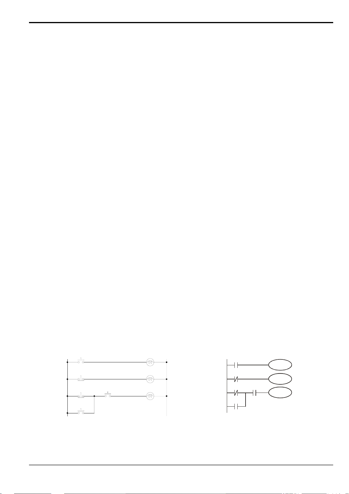
1. Combination Logic
Examples of traditional ladder diagram and PLC ladder diagram for combination logic:
Traditional Ladder Diagram PLC Ladder Diagram
X0
X1
X2
X3
X4
Y0
Y1
Y2
X0
Y0
X1
X2
X3
X4
Y1
Y2
Row 1: Using a normally open (NO) switch X0 (“A” switch or “A" contact). When X0 is not pressed, the contact
will be open loop (Off), so Y0 will be Off. When X0 is pressed, the contact will be On, so Y0 will be On.
DVP-PLC Application Manual
1-1
Page 6
1 Basic Principles of PLC Ladder Diagram
Row 2: Using a normally closed (NC) switch X1 (“B” switch or “B” contact). When X1 is not pressed, the contact
will be On, so Y1 will be On. When X1 is pressed, the contact will be open loop (Off), so Y1 will be Off.
Row 3: The combination logic of more than one input devices. Output Y2 will be On when X2 is not pressed or
X3 and X4 are pressed.
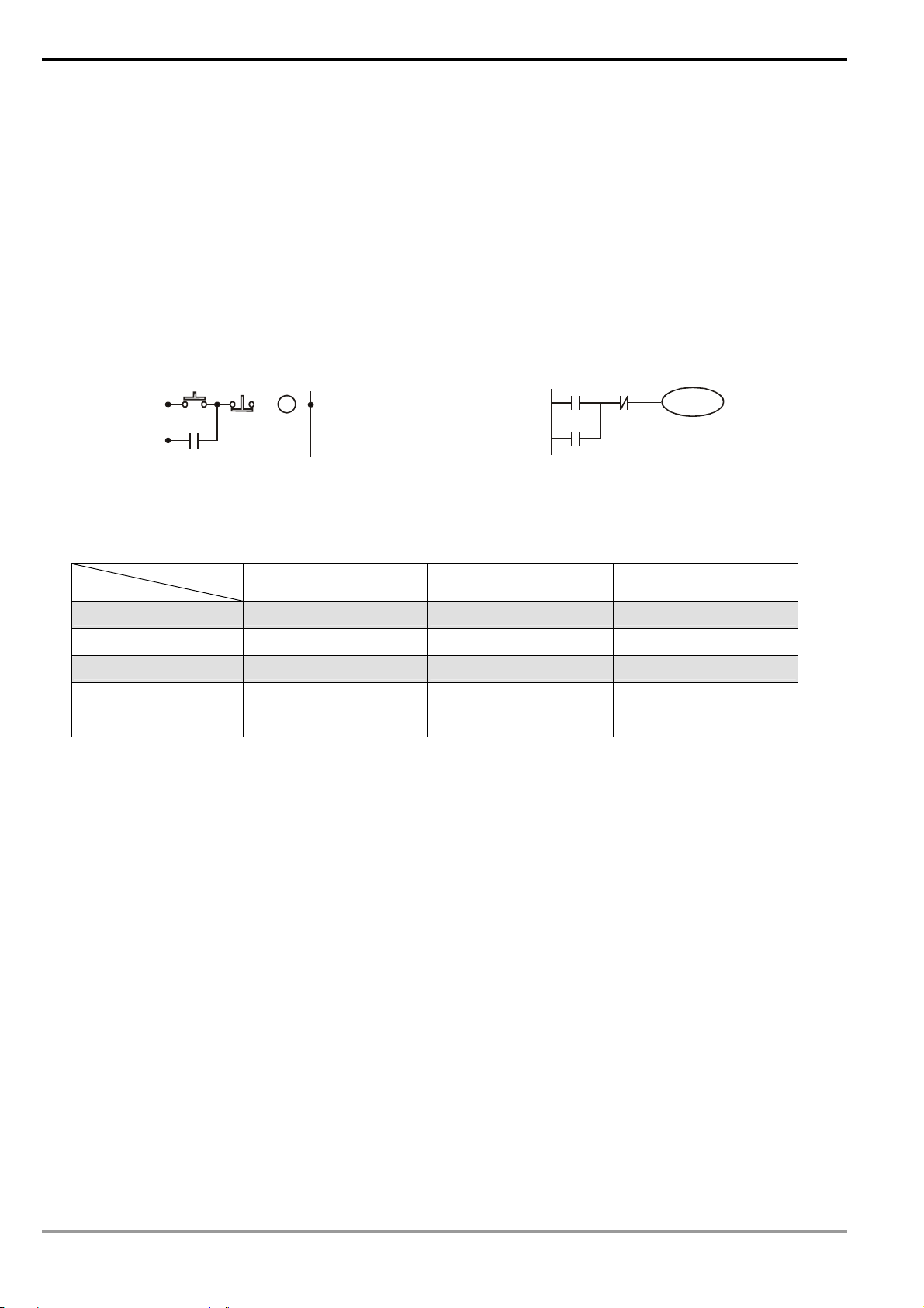
2. Sequential Logic
Sequential logic is a circuit with "draw back” structure, i.e. the output result of the circuit will be drawn back as an
input criterion. Therefore, under the same input criteria, different previous status or action sequence will follow by
different output results.
Examples of traditional ladder diagram and PLC ladder diagram for sequential logic:
Traditional Ladder Diagram PLC Ladder Diagram
X5
Y3
X6
Y3
X5
Y3
X6
Y3
When the circuit is first connected to the power, though X6 is On, X5 is Off, so Y3 will be Off. After X5 is pressed,
Y3 will be On. Once Y3 is On, even X5 is released (Off), Y3 can still keep its action because of the draw back (i.e.
the self-retained circuit). The actions are illustrated in the table below.
Device status
Action sequence
X5
X6 Y3
1 No action No action Off
2 Action No action On
3 No action No action On
4 No action Action Off
5 No action No action Off
From the table above, we can see that in different sequence, the same input status can result in different output
results. For example, switch X5 and X6 of action sequence 1 and 3 do not act, but Y3 is Off in sequence 1 and
On in sequence 3. Y3 output status will then be drawn back as input (the so-called “draw back”), making the
circuit being able to perform sequential control, which is the main feature of the ladder diagram circuit. Here we
only explain contact A, contact B and the output coil. Other devices are applicable to the same method. See
Chapter 3 “Basic instructions” for more details.
1.2 Differences Between Traditional Ladder Diagram and PLC Ladder Diagram
Though the principles of traditional ladder diagram and PLC ladder diagram are the same, in fact, PLC adopts
microcomputer to simulate the motions of the traditional ladder diagram, i.e. scan-check status of all the input devices
and output coil and calculate to generate the same output results as those from the traditional ladder diagram based
on the logics of the ladder diagram. Due to that there is only one microcomputer, we can only check the program of
the ladder diagram one by one and calculate the output results according to the program and the I/O status before the
cyclic process of sending the results to the output interface Æ re-reading of the input status Æ calculation Æ output.
The time spent in the cyclic process is called the “scan time” and the time can be longer with the expansion of the
program. The scan time can cause delay from the input detection to output response of the PLC. The longer the delay,
1-2
DVP-PLC Application Manual
Page 7
1 Basic Principles of PLC Ladder Diagram
the bigger the error is to the control. The control may even be out of control. In this case, you have to choose a PLC
with faster scan speed. Therefore, the scan speed is an important specification requirement in a PLC. Owing to the
advancement in microcomputer and ASIC (IC for special purpose), there has been great improvement in the scan
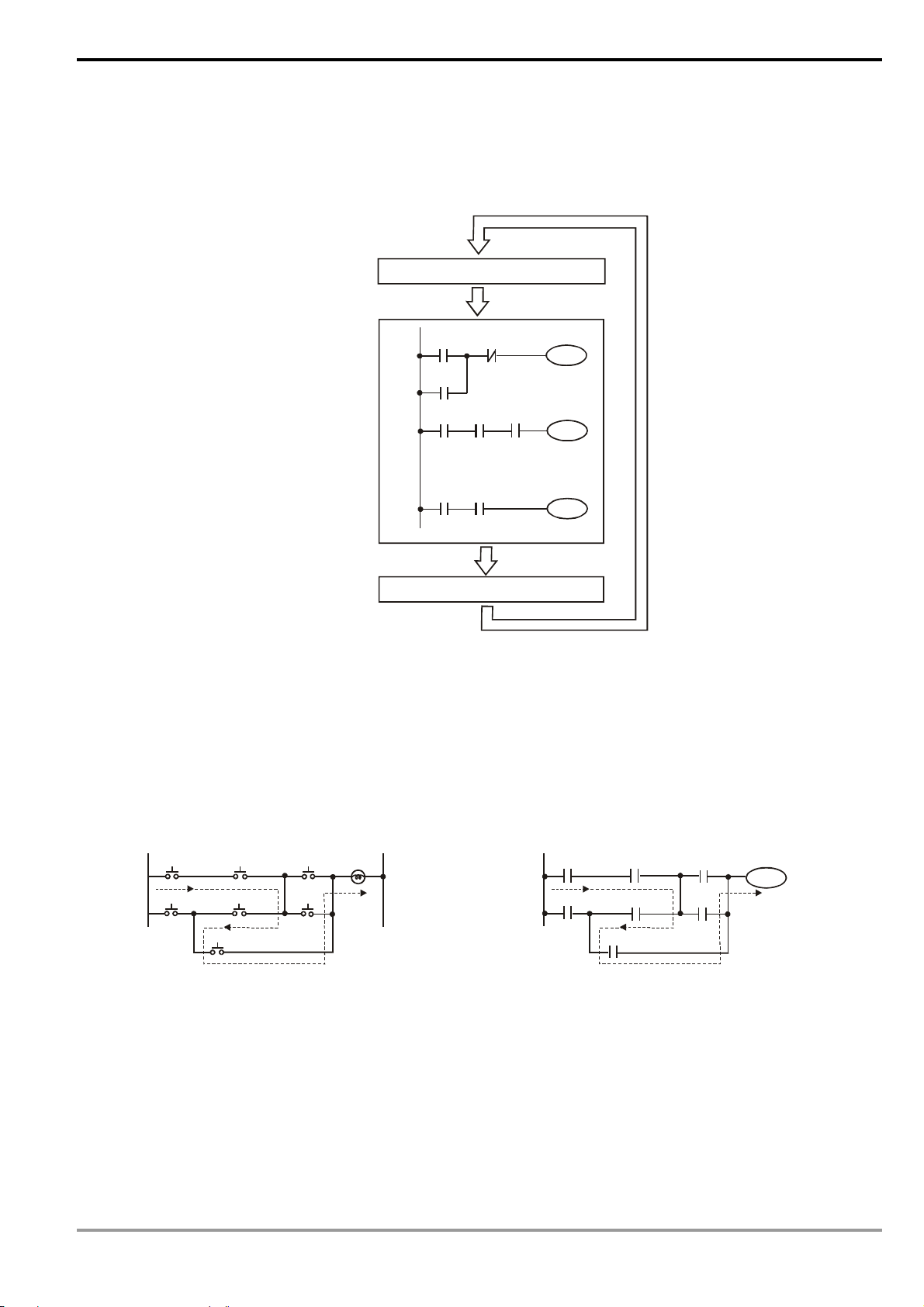
speed of PLC nowadays. See the figure below for the scan of the PLC ladder diagram program.
Read input status from outside
X0 X1
The output result is calculated
based on the ladder diagram.
(The result has not yet sent to the
external output point, but the
internal device will perform an
immediate output.)
Start
Y0
X3
M100
:
:
X100 M505
X10
Y0
Executing in cycles
Y1
Y126
End
Send the result to the output point
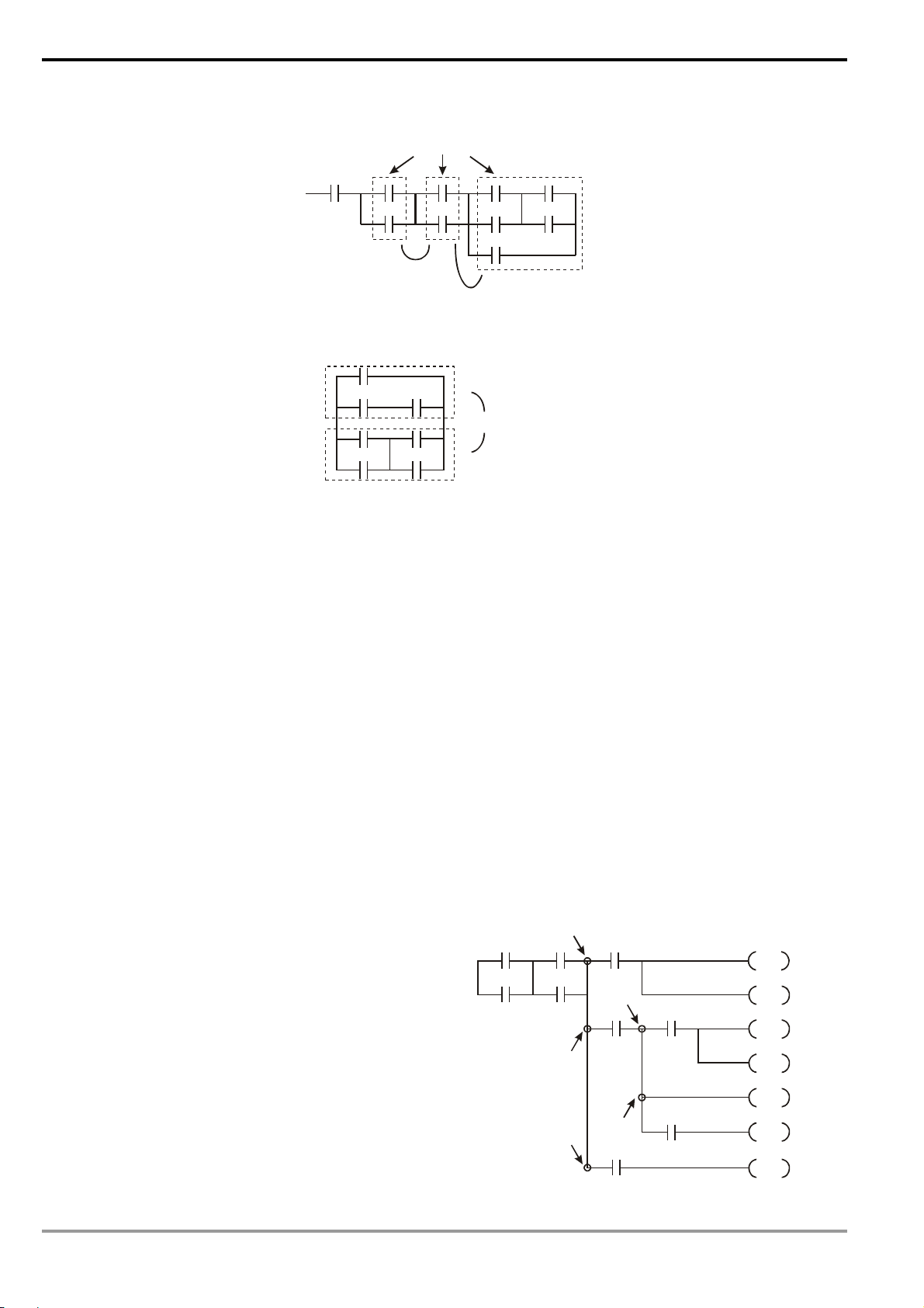
Besides the difference in the scan time, PLC ladder and traditional ladder diagram also differ in “reverse current”.
For example, in the traditional ladder diagram illustrated below, when X0, X1, X4 and X6 are On and others are Off,
Y0 output on the circuit will be On as the dotted line goes. However, the PLC ladder diagram program is scanned from
up to down and left to right. Under the same input circumstances, the PLC ladder diagram editing tool WPLSoft will be
able to detect the errors occurring in the ladder diagram.
Reverse current of traditional ladder diagram
X0
X3
a
X6
X1 X2
X4
X5
b
Y0
Error detected in the third row
Reverse current of PLC ladder diagram
X0
X3
a
X6
X1
X4 X5
b
X2
Y0
Y0
1.3 How to Edit Ladder Diagram
Ladder diagram is a diagram language frequently applied in automation. The ladder diagram is composed of the
symbols of electric control circuit. The completion of the ladder diagram by the ladder diagram editor is the completion
of the PLC program design. The control flow illustrated by diagram makes the flow more straightforward and
acceptable for the technicians of who are familiar with the electric control circuit. Many basic symbols and actions in
DVP-PLC Application Manual
1-3
Page 8

1 Basic Principles of PLC Ladder Diagram
the ladder diagram come from the frequently-seen electromechanical devices, e.g. buttons, switches, relay, timer and
counter, etc. in the traditional power panel for automation control.
Internal devices in the PLC: The types and quantity of the devices in the PLC vary in different brand names.
Though the internal devices in the PLC adopts the names, e.g. transistor, coil, contact and so on, in the traditional
electric control circuit, these physical devices do not actually exist inside the PLC. There are only the corresponding
basic units (1 bit) inside the memory of the PLC. When the bit is “1”, the coil will be On, and when the bit is “0”, the coil
will be Off. The normally open contact (NO or contact A) directly reads the value of the corresponding bit. The
normally close contact (NC or contact B) reads the opposite state of the value of the corresponding bit. Many relays
will occupy many bits. 8 bits equal a “byte”. 2 bytes construct a “word” and 2 words combined is “double word”. Byte,
word or double words are used when many relays are processed (e.g. addition/subtraction, displacement) at the
same time. The other two devices, timer and counter, in the PLC have coil, timer value and counter value and they
have to process some values in byte, word or double word.
All kinds of internal devices in the value storage area in the PLC occupy their fixed amount of storage units.
When you use these devices, you are actually read the contents stored in the form of bit, byte or word.
Introductions on the basic internal devices in the PLC (See Ch 2. Functions of Devices in DVP-PLC for more details.)
Device Functions
The input relay is an internal memory (storage) unit in the PLC corresponding to a external
input point and is used for connecting to the external input switches and receiving external
input signals. The input relay will be driven by the external input signals which make it “0” or
“1". Program designing cannot modify the status of the relay, i.e. it cannot re-write the basic
unit of a relay, nor can it force On/Off of the relay by HPP/WPLSoft. SA/SX/SC/EH/EH2/SV
series MPU can simulate input relay X and force On/Off of the relay. But the status of the
Input relay
external input points will be updated and disabled, i.e. the external input signals will not be read
into their corresponding memories inside PLC, but only the input points on the MPU. The input
points on the extension modules will still operate normally. There are no limitations on the times
of using contact A and contact B of the input relay. The input relays without corresponding input
signals can only be left unused and cannot be used for other purposes.
& Device indication: X0, X1,…X7, X10, X11,… are indicated as X and numbered in octal
form. The No. of input points are marked on MPU and extension modules.
The output relay is an internal memory (storage) unit in the PLC corresponding to a external
Output relay
1-4
output point and is used for connecting to the external load. The output relay will be driven by
the contact of an input relay, contacts of other internal devices and the contacts on itself. A
normally open contact of the output relay is connected to the external load. Same as the input
contacts, there are no limitations on the times of using other contacts of the output relay. The
output relay without corresponding output signals can only be left unused and can be used as
input relay if necessary.
& Device indication: Y0, Y1,…Y7, Y10, Y11,…are indicated as Y and numbered in octal
form. The No. of output points are marked on MPU and extension modules.
DVP-PLC Application Manual
Page 9

Internal relay
Step
1 Basic Principles of PLC Ladder Diagram
The internal relay does not have connection with the external. It is an auxiliary relay inside the
PLC with the functions same as those of the auxiliary (middle) relay in the electric control
circuit. Every internal relay corresponds to a basic internal storage unit and can be driven by
the contacts of the input relay, contacts of the output relay and the contacts of other internal
devices. There are no limitations on the times of using the contacts of the internal relay and
there will be no output from the internal relay, but from the output point.
& Device indication: M0, M1,…, M4095 are indicated as M and numbered in decimal form.
DVP series PLC offers a step-type control program input method. STL instruction controls the
transfer of step S, which makes it easy for the writing of the control program. If you do not use
any step program in the control program, step S can be used as a internal relay M as well as an
alarm point.
& Device indication: S0, S1,…S1023 are indicated as S and numbered in decimal form.
The timer is used for timing and has coil, contact and register in it. When the coil is On and the
Timer
Counter
Data register
estimated time is reached, its contact will be enabled (contact A closed, contact B open). Every
timer has its fixed timing period (unit: 1ms/10ms/100ms). Once the coil is Off, the contact iwlwl
be disabled (contact A open, contact B closed) and the present value on the timer will become
“0”.
& Device indication: T0, T1,…,T255 are indicated as T and numbered in decimal form.
Different No. refers to different timing period.
The counter is used for counting. Before using the counter, you have to give the counter a set
value (i.e. the number of pulses for counting). There are coil, contact and registers in the
counter. When the coil goes from Off to On, the counter will regard it as an input of 1 pulse and
the present value on the counter will plus “1”. We offer 16-bit and 32-bit high-speed counters
for our users.
& Device indication: C0, C1,…,C255 are indicated as C and numbered in decimal form.
Data processing and value operations always occur when the PLC conducts all kinds of
sequential control, timing and counting. The data register is used for storing the values or all
kinds of parameters. Every register is able to store a word (16-bit binary value). Double words
will occupy 2 adjacent data registers.
& Device indication: D0, D1,…,D9,999 are indicated as D and numbered in decimal form.
DVP-PLC Application Manual
1-5
Page 10
1 Basic Principles of PLC Ladder Diagram
The file register is used for storing the data or all kinds of parameters when the data registers
required for processing the data and value operations are insufficient. Every file register is able
to store a 16-bit word. Double words will occupy 2 adjacent file registers. In SA/SX/SC series
File register
Index register
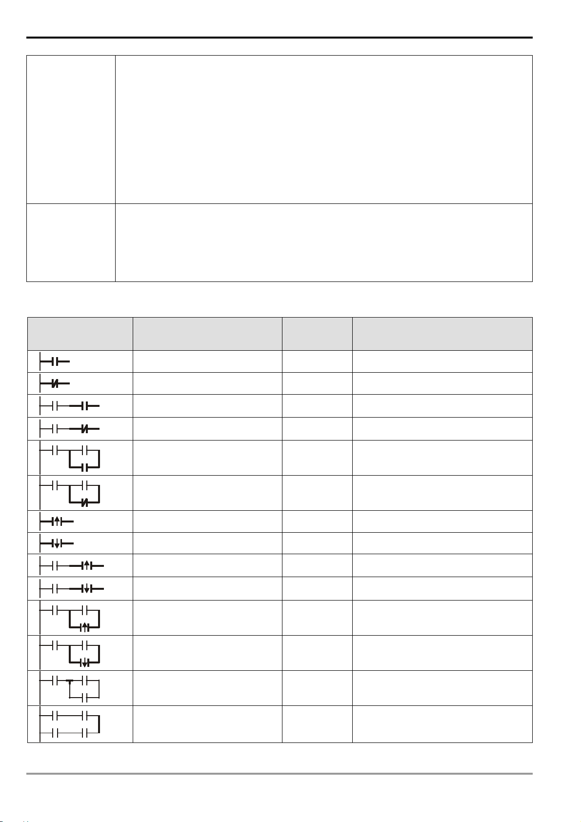
The structure of a ladder diagram:
Structure Explanation Instruction Devices Used
MPU, there are 1,600 file registers. In EH/EH2/SV series MPU, there are 10,000 file registers.
There is not an actual device No. for a file register. The reading and writing of file registers
should be executed by instructions API 148 MEMR, API 149 MEMW, or through the peripheral
device HPP02 and WPLSoft.
& Device indication: K0 ~ K9,999, numbered in decimal form.
E and F index registers are 16-bit data registers as other data registers. They can be read and
written and can be used in word devices, bit devices or as a constant for index indication.
& Device indication: E0 ~ E7, F0 ~ F7 are indicated as E and F and numbered in decimal
form.
Normally open, contact A LD X, Y, M, S, T, C
Normally closed, contact B LDI X, Y, M, S, T, C
Normally open in series
connection
Normally closed in series
connection
AND X, Y, M, S, T, C
ANI X, Y, M, S, T, C
Normally open in parallel
connection
Normally closed in parallel
connection
Rising-edge trigger switch LDP X, Y, M, S, T, C
Falling-edge trigger switch LDF X, Y, M, S, T, C
Rising-edge trigger in series
connection
Falling-edge trigger in series
connection
Rising-edge trigger in parallel
connection
Falling-edge trigger in parallel
connection
Block in series connection ANB -
Block in parallel connection ORB -
OR X, Y, M, S, T, C
ORI X, Y, M, S, T, C
ANDP X, Y, M, S, T, C
ANDF X, Y, M, S, T, C
ORP X, Y, M, S, T, C
ORF X, Y, M, S, T, C
1-6
DVP-PLC Application Manual
Page 11
1 Basic Principles of PLC Ladder Diagram
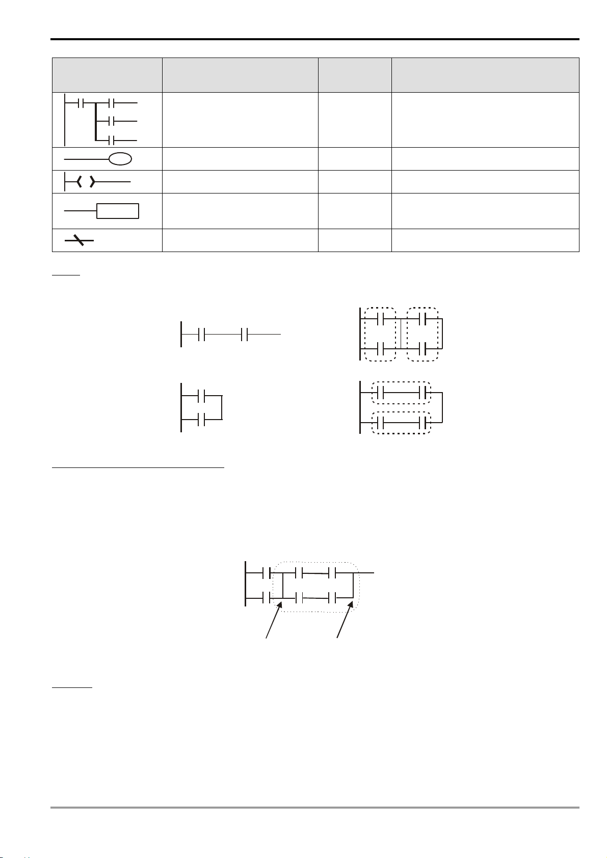
Structure Explanation Instruction Devices Used
MPS
Multiple output
Coil driven output instruction OUT Y, M, S
MRD
MPP
-
SS
Block:
A block is a series or parallel operation composed of more than 2 devices. There are series block and parallel block.
Series block
Step ladder STL S
Basic instruction
Application instruction
Inverse logic INV -
Application
instructions
See Ch.3 for basic instructions
(RST/SET and CNT/TMR) and Ch.5 ~
10 for application instructions
Parallel block
Separation line and combination line:
The vertical line is used for separating the devices. For the devices on the left, the vertical line is a combination line,
indicating that there are at least 2 rows of circuits on the left connected with the vertical line. For the devices on the
right, the vertical line is a separation line, indicating that there are at least 2 rows of circuits interconnected on the right
side of the vertical line).
1
Combination line for block 1
Separation line for block 2
Network:
A complete block network is composed of devices and all kinds of blocks. The blocks or devices connectable by a
vertical line or continuous line belong to the same network.
2
Combination line for block 2
DVP-PLC Application Manual
1-7
Page 12
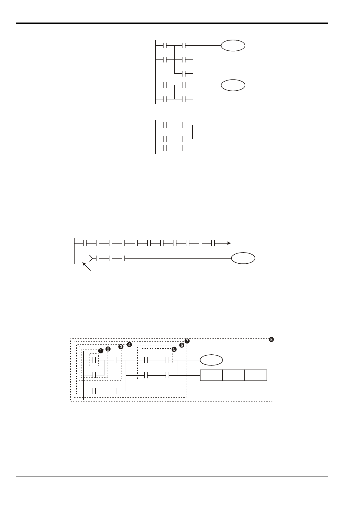
1 Basic Principles of PLC Ladder Diagram
Network 1
An independent network
Network 2
An incomplete network
1.4 How to Edit a PLC Ladder Diagram
The editing of the program should start from the left power line and ends at the right power line, a row after
another. The drawing of the right power line will be omitted if edited from WPLSoft. A row can have maximum 11
contacts on it. If 11 is not enough, you can continuously connect more devices and the continuous number will be
generated automatically. The same input points can be used repeatedly. See the figure below:
X0 X1 X2 X3 X4 X5
X11 X12 X13
00000
Continuous number
X6 X7 X10 C0 C1
00000
Y0
The operation of the ladder diagram program is scanning from top left to bottom right. The coil and the operation
frame of the application instruction belong to the output side in the program and are placed in the right if the ladder
diagram. Take the figure below for example, we will step by step explain the process of a ladder diagram. The
numbers in the black circles indicate the order.
X0 X1 Y1 X4
M0
X3
M1
Y1
T0
M3
TMR T0 K10
The order of the instructions:
1 LD X0
2 OR M0
3 AND X1
4 LD X3
AND M1
1-8
DVP-PLC Application Manual
Page 13
1 Basic Principles of PLC Ladder Diagram
n
ORB
5 LD Y1
AND X4
6 LD T0
AND M3
ORB
7 ANB
8 OUT Y1
TMR T0 K10
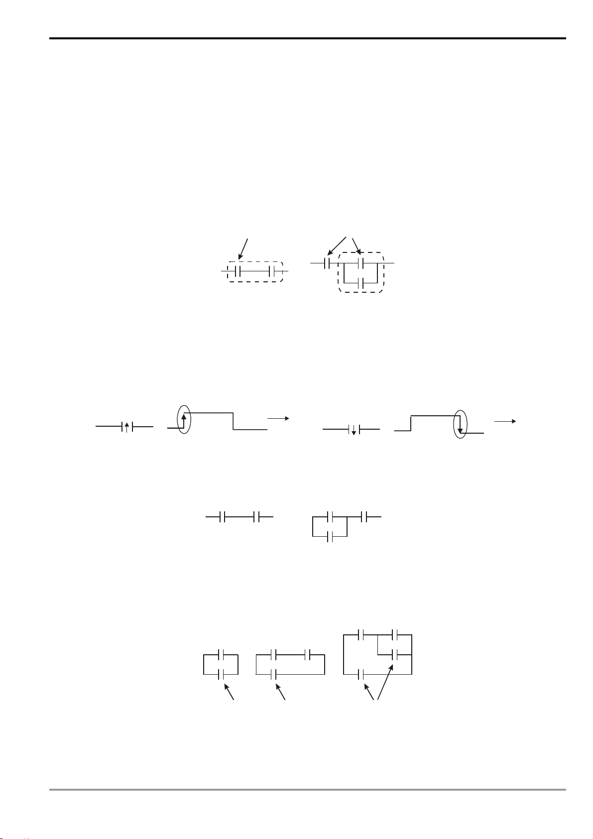
Explanations on the basic structures in the ladder diagram:
1. LD (LDI) instruction: Given in the start of a block.
LD instruction LD instruction
AND block OR block
The structure of LDP and LDF instructions are the same as that of LD instruction, and the two only differ in their
actions. LDP and LDF instructions only act at the rising edge or falling edge when the contact is On, as shown in the
figure below.
X0
Rising edge
OFF
ON
OFF
Time
X0
OFF
Falling edge
ON
OFF
Time
2. AND (ANI) instruction: A single device connects to another single device or a block in series
AND instructio
AND instruction
The structure of ANDP and ANDF instructions are the same. ANDP and ANDF instructions only act at the rising
edge or falling edge.
3. OR (ORI) instruction: A single device connects to another single device or a block
OR instruction OR instruction OR instruction
The structure of ORP and ORF instructions are the same. ORP and ORF instructions only act at the rising edge
or falling edge.
DVP-PLC Application Manual
1-9
Page 14
1 Basic Principles of PLC Ladder Diagram
4. ANB instruction: A block connects to a device or another block in series
ANB instruction
5. ORB instruction: A block connects to a device or another block in parallel
ORB instruction
If the ANB and ORB operations are with several blocks, the operation should be performed from up to down or
left to right, combining into a block or network.
6. MPS, MRD, MPP instructions: Bifurcation point of multiple outputs, for generating many and diverse outputs.
MPS instruction is the start of the bifurcation point. The bifurcation point is the intersection of the horizontal line
and vertical line. We will have to determine whether to give a contact memory instruction by the contact status of the
same vertical line. Basically, every contact can be given a memory instruction, but considering the convenience of
operating the PLC and the limitation on its capacity, some parts in the ladder diagram will be omitted during the
conversion. We can determine the type of contact memory instruction by the structure of the ladder diagram. MPS is
recognized as “┬” and the instruction can be given continuously for 8 times.
MRD instruction is used for reading the memory of the bifurcation point. Due to that the same vertical line is of
the same logic status, in order to continue analyzing other ladder diagrams, we have to read the status of the original
contact again. MRD is recognized as “├”.
MPP instruction is used for reading the start status of the top bifurcation point and popping it out from the stack.
Since MPP is the last item on the vertical line, the vertical line ends at this point.
MPP is recognized as “└”. Using the method
MPS
given above for the analysis cannot be wrong.
However, sometimes the compiling program will ignore
MPS
the same output status, as shown in the figure.
1-10
MRD
MPP
MPP
DVP-PLC Application Manual
Page 15
1 Basic Principles of PLC Ladder Diagram
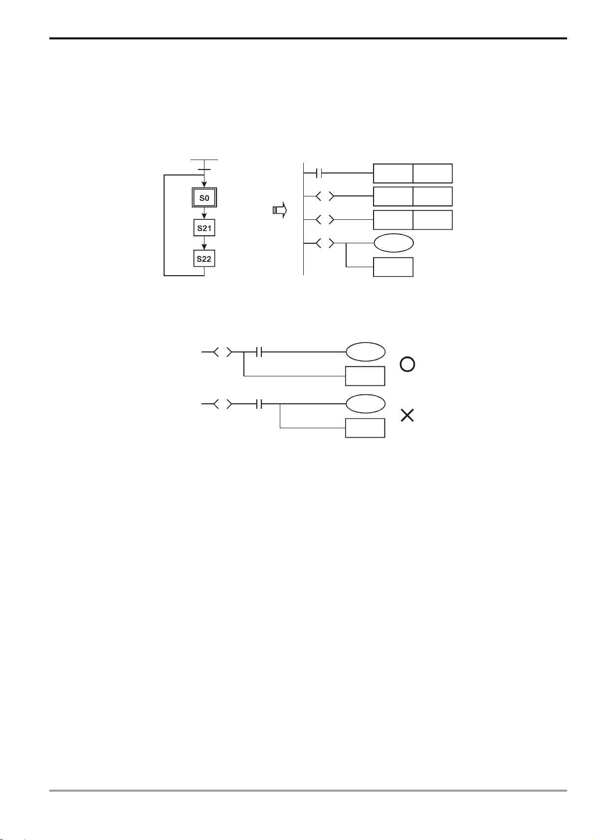
7. STL instruction: Used for designing the syntax of the sequential function chart (SFC).
STL instruction allows the program designer a clearer and readable picture of the sequence of the program as
when they draw a sequence chart. From the figure below, we can see clearly the sequence to be planned. When the
step S moves to the next step, the original S will be “Off". Such a sequence can then be converted into a PLC ladder
diagram and called “step ladder diagram”.
M1002
M1002
S0
S
S21
S
S22
S
8. RET instruction: Placed after the completed step ladder diagram.
RET also has be placed after STL instruction. See the example below.
S20
S
S20
S
X1
X1
RET
RET
SET
SET
SET
S0
RET
S0
S21
S22
See step ladder instructions [STL], [RET] in Ch. 4 for the structure of the ladder diagram.
DVP-PLC Application Manual
1-11
Page 16
1 Basic Principles of PLC Ladder Diagram
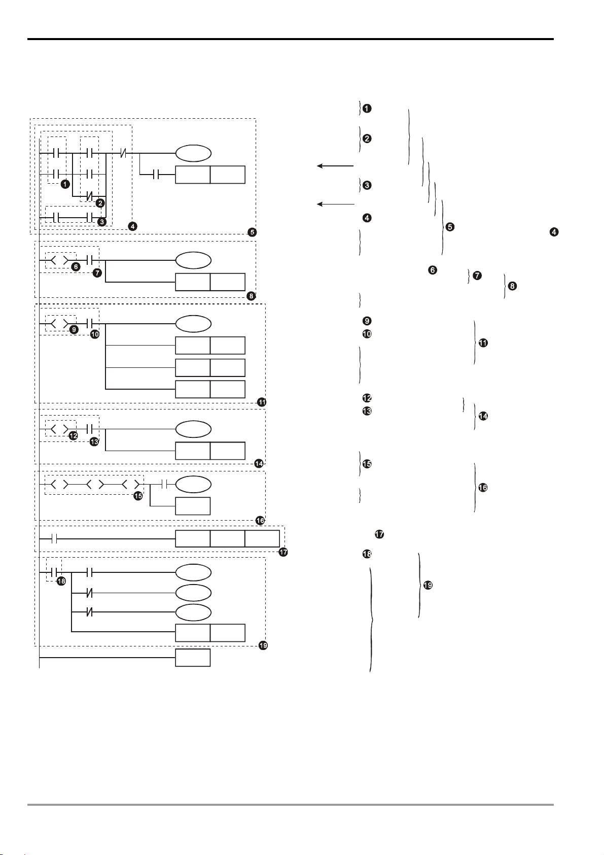
1.5 The Conversion of PLC Command and Each Diagram Structure
Ladder Diagram
X0 X2 X1
S0
S
S
S
S
M0
M1
Y0
X10
X11
X12
S12SS13
X1
X1
M2
X1
M2
S10
S11
S20
X0
C0
LD X0
OR X1
LD X2
OR M0
Y0
C0
SET S0
OR I M1
ANB
LD M2
AND Y0
ORB
AN I X1
OU T Y0
AND C0
Y10
SET S0
STL S0
SET S10
LD X10
OU T Y10
SET S10
Y11
STL S10
LD X11
SET S11
SET S12
SET S13
OU T Y11
SET S11
SET S12
SET S13
STL S11
LD X12
Y12
OU T Y12
SET S20
SET S20
STL S20
STL S12
X13
S
S0
RET
STL S13
LD X13
OU T S0
RET
LD X0
CNT
C0
K10
CNT C0 K 10
LD C0
M0
MPS
AND X1
M1
M2
RST C0
OU T M0
MRD
AN I X1
OU T M1
MPP
END
AN I M2
OU T M2
RST C0
END
OR
block
OR
block
Series
connection blcok
AND
block
Parallel
connection block
ANI
Multiple
outputs
Step ladder Start
Status S0 and X10 operation
Status working item and
step point transfer
Withdraw S10 status
Withdraw X11 status
Status working item and
step point transfer
Withdraw S11 status
Withdraw X12 status
Status working item and
step point transfer
Bifurcation
convergence
Status working item
and step point transfer
Return
Read C0
Multiple
outputs
End of program
The output will continue
following the status of
End of step ladder
Fuzzy Syntax
The correct ladder diagram analysis and combination should be conducted from up to down and left to right.
However, without adopting this principle, some instructions can make the same ladder diagram.
1-12
DVP-PLC Application Manual
Page 17
1 Basic Principles of PLC Ladder Diagram
Example Program 1
See the ladder diagram below. There are 2 ways to indicate the ladder by instruction programs with the same result.
X0 X2 X4
Ideal way Less ideal way
LD X0 LD X0
X5X3X1
OR X1 OR X1
LD X2 LD X2
OR X3 OR X3
ANB LD X4
LD X4 OR X5
OR X5 ANB
ANB ANB
The two instruction programs will be converted into the same ladder diagram. The difference between the ideal
one and less ideal one is the operation done by the MPU. For the ideal way, the combination is done block by block
whereas the less idea way combines all the blocks combine with one another in the last step. Though the length of
the program codes of the two ways are equal, the combination done in the last step (by ANB instruction, but ANB
cannot be used continuously for more than 8 times) will have to store up the previous calculation results in advance.
In our case, there are only two blocks combined and the MPU allows such kind of combination. However, once the
number of blocks exceed the range that the MPU allows, problems will occur. Therefore, the best way is to execute
the block combination instruction after a block is made, which will also make the logic sequence planned by the
programmer more in order.
Example Program 2
See the ladder diagram below. There are 2 ways to indicate the ladder by instruction programs with the same result.
Ideal way Less ideal way
X0
X1
X2
LD X0 LD X0
OR X1 LD X1
OR X2 LD X2
OR X3 LD X3
X3
ORB
ORB
ORB
In this example, the program codes and the operation memory in the MPU increase in the less ideal way.
Therefore, it is better that you edit the program following the defined sequence.
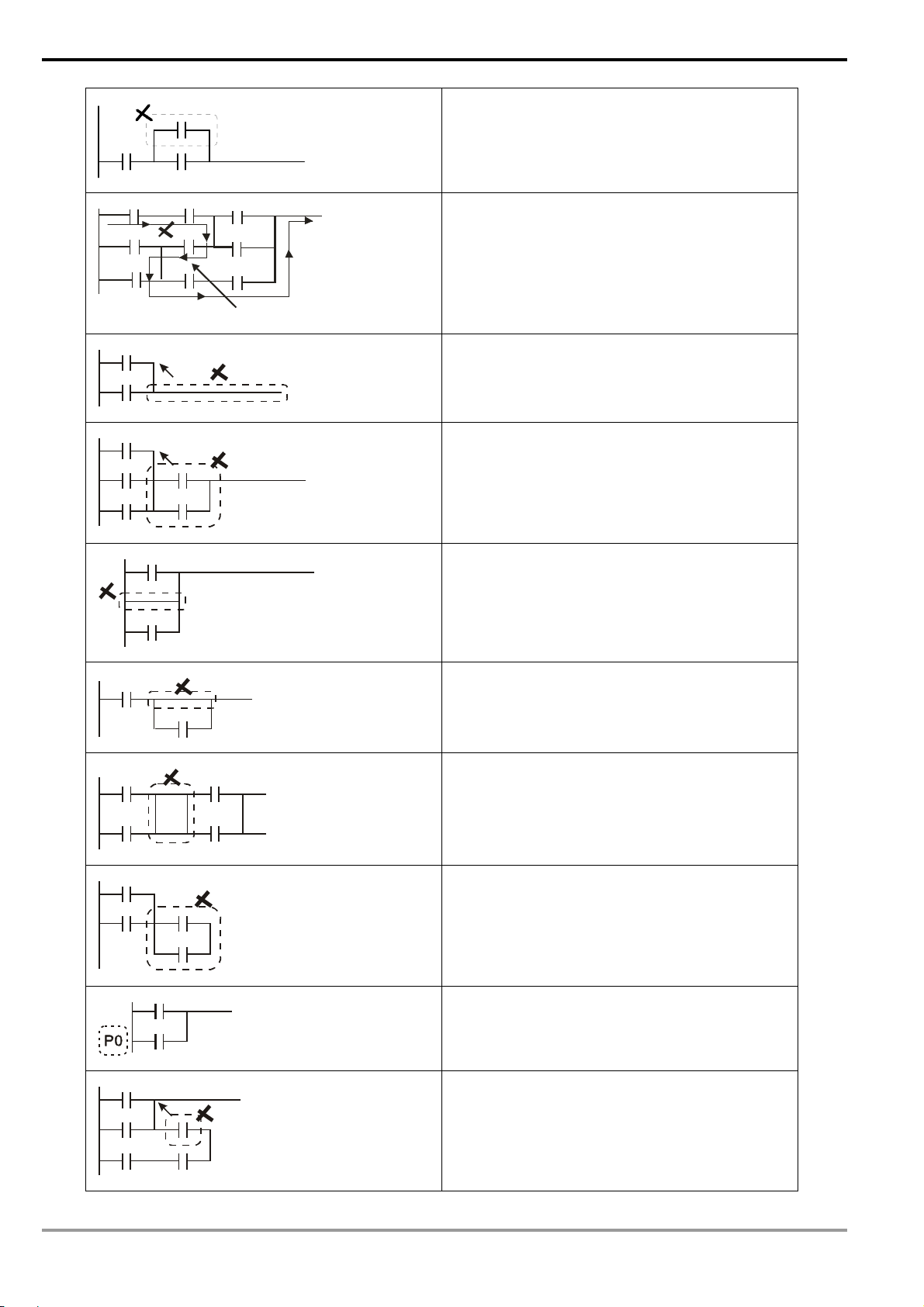
Incorrect Ladder Diagram
PLC processes the diagram program from up to down and left to right. Though we can use all kinds of ladder
symbols to combine into various ladder diagrams, when we draw a ladder diagram, we will have to start the diagram
from the left power line and end it at the right power line (In WPLSoft ladder diagram editing area, the right power line
is omitted), from left to right horizontally, one row after another from up to down. See bellows for the frequently seen
incorrect diagrams:
DVP-PLC Application Manual
1-13
Page 18
1 Basic Principles of PLC Ladder Diagram
OR operation upward is not allowed.
“Reverse flow” exists in the signal circuit from the
beginning of input to output.
Re verse flow
The up-right corner should output first.
Combining or editing should be done from the
up-left to the bottom-right. The dotted-lined area
should be moved up.
Parallel operation with empty device is not allowed.
Empty device cannot do operations with other
devices.
1-14
No device in the middle block.
Devices and blocks in series should be horizontally
aligned.
Label P0 should be in the first row of a complete
network.
Blocks connected in series should be aligned with
the upmost horizontal line.
DVP-PLC Application Manual
Page 19
1 Basic Principles of PLC Ladder Diagram
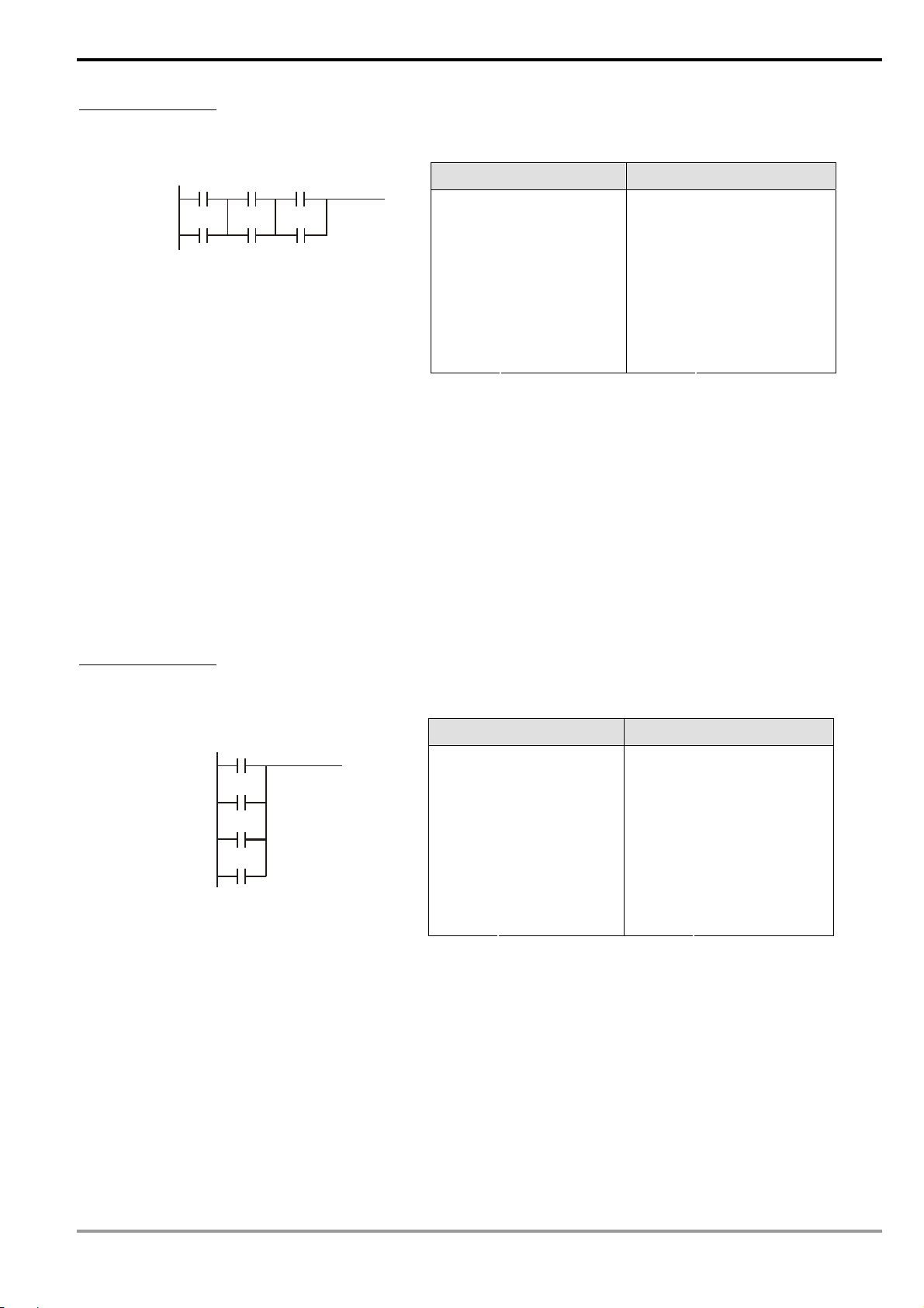
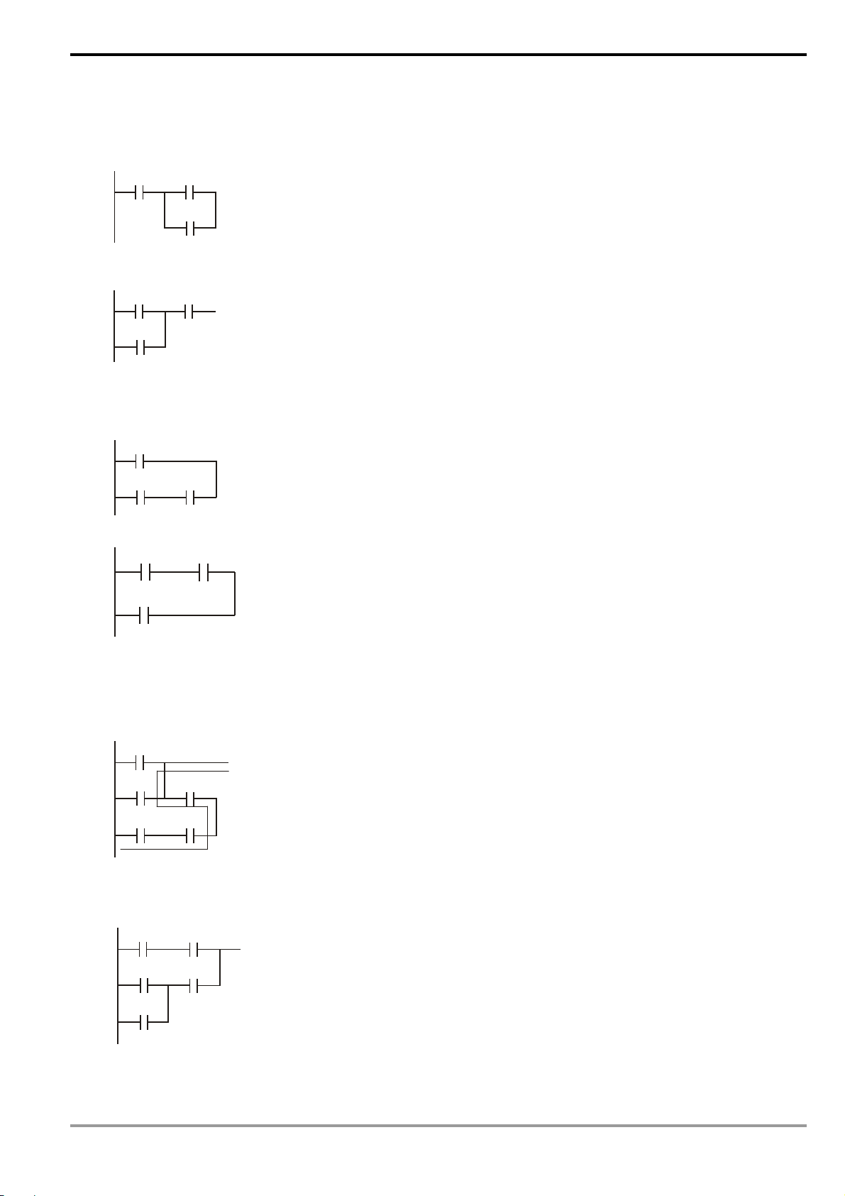
1.6 Simplified Ladder Diagram
When a series block is connected to a parallel block in series, place the block in the front to omit ANB instruction.
X0 X1
Ladder diagram complied into instruction
LD X0
X2
Ø
X0X1
LD X1
OR X2
ANB
Ladder diagram complied into instruction
LD X1
X2
OR X2
AND X0
When a single device is connected to a block in parallel, place the block on top to omit ORB instruction.
T0
Ladder diagram complied into instruction
LD T0
X1
X1
X2
X2
Ø
LD X1
AND X2
ORB
Ladder diagram complied into instruction
LD X1
T0
AND X2
OR T0
In diagram (a), the block on top is shorter than the block in the bottom, we can switch the position of the two
blocks to achieve the same logic. Due to that diagram (a) is illegal, there is a “reverse flow” in it.
Ladder diagram complied into instruction
X0
LD X0
X1
X3
X2
X4
OR X1
AND X2
LD X3
(a)
Ø
AND X4
ORB
Ladder diagram complied into instruction
X3
X1
X4
X2
LD X3
AND X4
LD X1
X0
(b)
OR X0
AND X2
DVP-PLC Application Manual
ORB
1-15
Page 20
1 Basic Principles of PLC Ladder Diagram
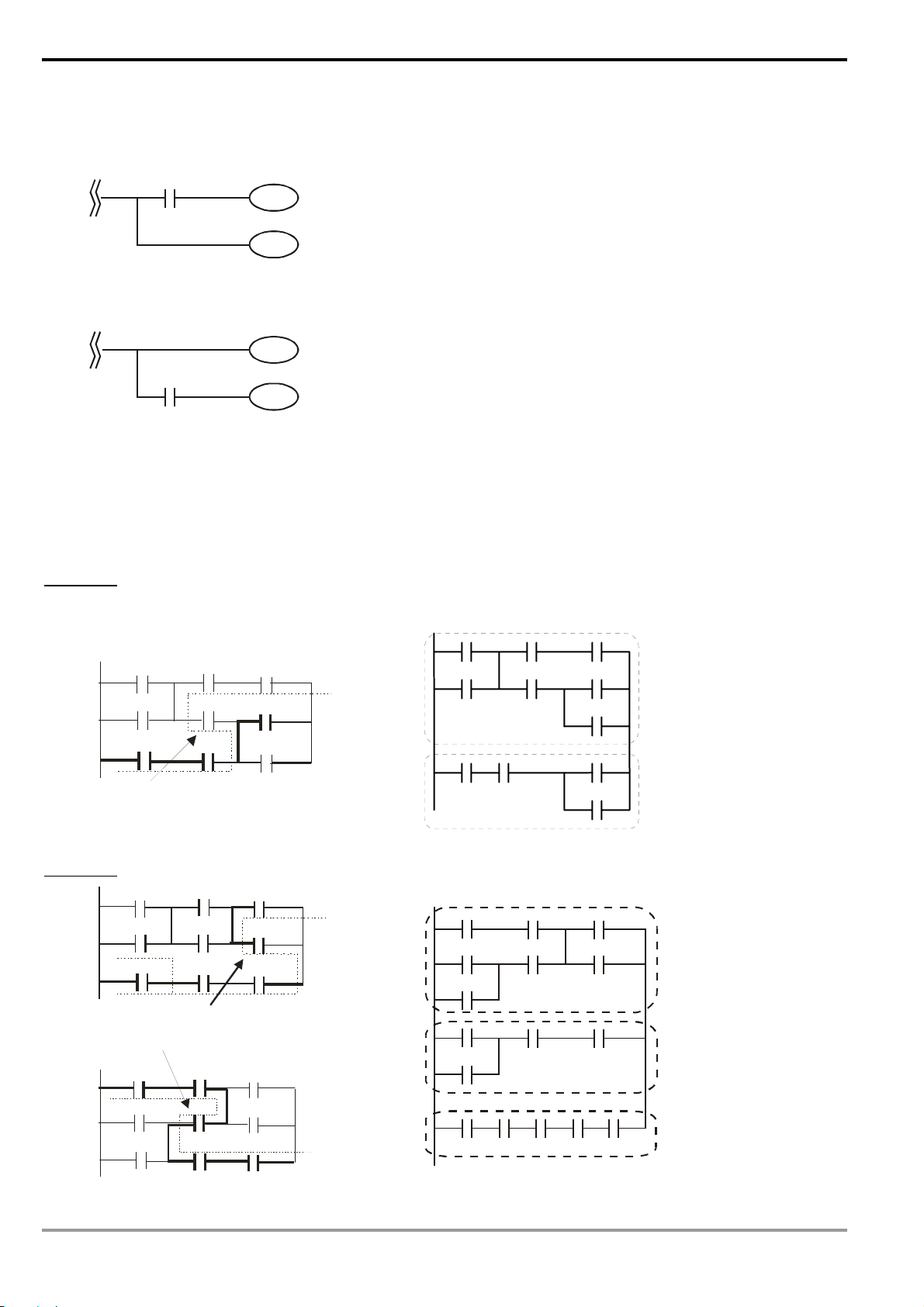
w
MPS and MPP instruction can be omitted when the multiple outputs in the same horizontal line do not need to
operate with other input devices.
X0
Y1
Ladder diagram complied into instruction
MPS
AND X0
Ø
Y0
OUT Y1
MPP
OUT Y0
Ladder diagram complied into instruction
X0
Y0
Y1
OUT Y0
AND X0
OUT Y1
Correct the circuit of reverse flow
In the following two examples, the diagram in the left hand side is the ladder diagram we desire. However, the illegal
“reverse flow” in it is incorrect according to our definition on the ladder diagram. We modify the diagram into the
diagram in the right hand side.
Example 1
Example 2
X0
X3
X6
rever se fl o
X0
X3
X6
Re verse f l ow
X0
X3
X1
X4
X7
X1
X4
X7
re ver se fl ow
X1
X4
X2
X10
X2
X5
X2
X5
X10
X5
LOOP 1
LO OP 1
X0 X1 X2
X3 X4 X5
X10
Ö
X6 X7 X5
X10
LOOP1
X0 X1 X2
X3 X4 X5
X6
X3 X7 X10
Ö
X6
LOOP1
X0 X1 X7 X10
X4
1-16
X6
X7
X10
LOOP2
LOOP
2
DVP-PLC Application Manual
Page 21
1 Basic Principles of PLC Ladder Diagram
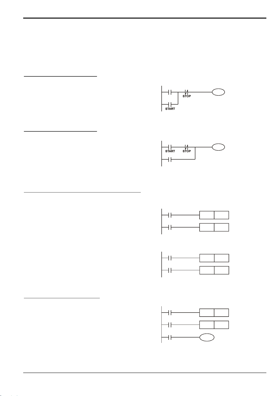
1.7 Basic Program Designing Examples
Start, Stop and Latched
In some application occasions, we need to use the transient close/open buttons for the start and stop of an equipment.
To maintain its continuous action, you have to design latched circuits.
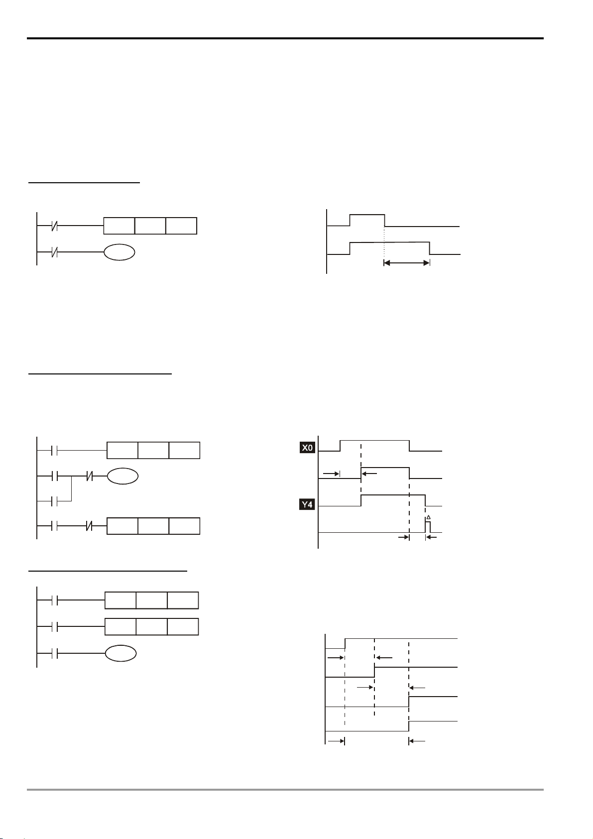
Example 1: Stop first latched circuit
When the normally open contact X1 = On and the
normally closed contact X2 = Off, Y1 will be On. If you make
X2 = On at this time, Y1 will be Off. It is the reason why this is
called “stop first”.
Example 2: Start first latched circuit
When the normally open contact X1 = On and the
normally closed contact X2 = Off, Y1 will be On and latched. If
you make X2 = On at this time, Y1 will continue to be On
because of the latched contact. It is the reason why this is
called “start first”.
Example 3: Latched circuit for SET and RST instructions
See the diagram in the right hand side for the latched
circuit consist of RST and SET instructions.
In the stop first diagram, RST is placed after SET. PLC
executes the program from up to down, so the On/Off of Y1 will
be determined upon its status in the end of the program.
Therefore, when X1 and X2 are enabled at the same time, Y1
will be Off. It is the reason why this is called “stop first”.
In the start first diagram, SET is placed after RST. When
X1 and X2 are enabled at the same time, Y1 will be On. It is
the reason why this is called “start first”.
Y1
X1
X1
Y1
Stop first
X1
X2
Start first
X2
X1
X2
X2
SET
RST
RST
SET
Y1
Y1
Y1
Y1
Y1
Y1
Example 4: Power shutdown latched
The auxiliary relay M512 is latched (see instruction
sheets for DVP series PLC MPU). The circuit can not only be
latched when the power is on, but also keep the continuity of
the original control when the power is shut down and switched
on again.
DVP-PLC Application Manual
X1
X2
M512
SET
M512
RST M512
Y1
1-17
Page 22

Frequently Used Control Circuit
1 Basic Principles of PLC Ladder Diagram
Example 5: Conditional control
X1
Y1
X2
Y2
X3
X4
Y1
X1
Y1
Y2
X3
X2
X4
Y1
Y2
X1 and X3 enables and disables Y1; X2 and X4 enables and disables Y2, and all are latched. Due to that the
normally open contact of Y1 is connected to the circuit of Y2 in series, Y1 becomes an AND condition for Y2.
Therefore, only when Y1 is enabled can Y2 be enabled.
Example 6: Interlock control
X1
Y1
X3
Y2
Y1
X1
X3
X2
X2
Y2
X4
Y1
Y2
X4
Y1
Y2
Which of the X1 and X2 is first enabled decides either the corresponding output Y1 or Y2 will be enabled first.
Either Y1 or Y2 will be enabled at a time, i.e. Y1 and Y2 will not be enabled at the same time (the interlock). Even X1
and X2 are enabled at the same time, Y1 and Y2 will not be enabled at the same time due to that the ladder diagram
program is scanned from up to down. In this ladder diagram, Y1 will be enabled first.
Example 7: Sequential control
X1
Y1
X2
Y2
X3
X4
Y2
Y1
If we serially connect the normally closed contact
Y1
of Y2 in example 5 to the circuit of Y1 as an AND
condition for Y1 (as the diagram in the left hand side),
the circuit can not only make Y1 as the condition for Y2,
Y2
but also allow the stop of Y1 after Y2 is enabled.
Therefore, we can make Y1 and Y2 execute exactly the
sequential control.
1-18
DVP-PLC Application Manual
Page 23

1 Basic Principles of PLC Ladder Diagram
Y1
Y1
T T
Example 8: Oscillating circuit
An oscillating circuit with cycle ΔT+ΔT
Y1
The ladder diagram above is a very simple one. When the program starts to scan the normally closed contact
Y1, Y1 will be closed because coil Y1 is Off. When the program then scan to coil Y1 and make it On, the output will be
1. When the program scans to the normally closed contact Y1 again in the next scan cycle, because coil Y1 is On, Y1
will be open and make coil Y1 Off and output 0. The repeated scans will result in coil Y1 outputs oscillating pulses by
the cycle ΔT(On)+ΔT(Off).
An oscillating circuit with cycle nT+ΔT
X0
T0
Y1
TMR
Y1
T0
Kn
X0
Y1
TTn
The ladder diagram program controls the On time of coil Y1 by timer T0 and disable timer T0 in the next scan
cycle, resulting in the oscillating pulses in the output of Y1. n refers to the decimal set value in the timer and T is the
cycle of the clock.
Example 9: Flashing circuit
X0
T1
X0 T1
T2
TMR
Y1
T1
T2TMR Kn2
Kn1
X0
Tn2
*
Y1
T
n1
*
The ladder diagram is an oscillating circuit which makes the indicator flash or enables the buzzer alarms. It
uses two timer to control the On/Off time of coil Y1. n1 and n2 refer to the set values in T1 and T2 and T is the cycle
of the clock.
Example 10: Trigger circuit
X0
M0
M0
M0
Y1
Y1
Y1
DVP-PLC Application Manual
X0
T
M0
Y1
1-19
Page 24
1 Basic Principles of PLC Ladder Diagram
The rising-edge differential instruction of X0 makes coil M0 generate a single pulse of ΔT (one scan cycle).
Coil Y1 will be On during this scan period. In the next scan period, coil M0 will be Off and the normally closed contact
M0 and Y1 will all be closed, making coil Y1 continue to be On until another rising-edge arrives in input X0, making
coil M0 On for another scan period and Y1 Off. Such kind of circuit relies on an input to make two actions execute
interchangeably. Also from the timing diagram on the last page, we can see that input X0 are square pulse signals of
the cycle T and coil Y1 output are square pulse signals of the cycle 2T.
Example 11: Delay circuit
X0
T10
TMR
Y1
T10
K1000
X0
Y1
Time base: T = 0.1 sec
100 seconds
When input X0 is On, due to that its corresponding normally closed contact is Off, time T10 will be Off and the
output coil Y1 will be On. T10 will be On and start to count until input X0 is Off. Output coil Y1 will be delayed for
100 seconds (K1,000 × 0.1 sec = 100 secs) and be Off. See the timing diagram above.
Example 12: Output delay circuit
The output delay circuit is the circuit composed of two timers. When input X0 is On and Off, output Y4 will be
delayed.
X0
T5
K50
5 secs
T5
T5
Y4
TMR
T6
Y4
Y4
X0
TMR
T6
K30
Example13: Timing extension circuit
X0
Y1
T11
T12TMR Kn2
Kn1
TMR
T11
T12
Timer = T11, T12
Clock cycle: T
1-20
T
T6
3 secs
The total delay time from input X0 is closed to output
Y1 is On = (n1+n2)* T. T refers to the clock cycle.
X0
T11
T12
Y1
n1*
T
(n1+n2)*
n2*
T
T
DVP-PLC Application Manual
Page 25
1 Basic Principles of PLC Ladder Diagram
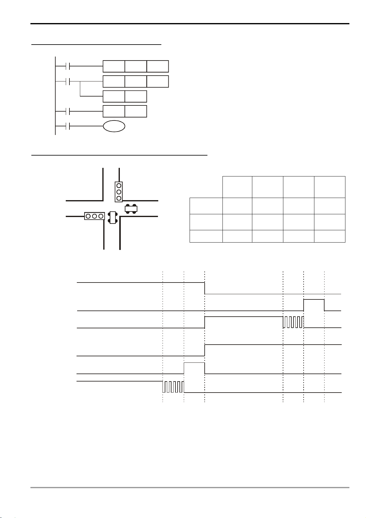
Kn1
The counting range of a 16-bit counter is 0 ~ 32,767. As
the circuit in the left hand side, using two counters can
increase the counting range to n1*n2. When the counting
of counter C5 reaches n1, C6 will start to count for one
time and reset for counting the pulses from X13. When
the counting of counter C6 reaches n2, the pulses from
input X13 will be n1*n2.
Example 14: How to enlarge the counting range
X13
CNT
C5
C5
C6CNT Kn2
C5RST
X14
RST
C6
C6
Y1
Example 15: Traffic light control (by using step ladder instruction)
Traffic light control
Vertical
Light
Vertical
light
Horizontal
Horizontal
Light
light
On time 35 secs 5 secs 25 secs 5 secs
Red light
Y0 Y1 Y2 Y2
Y10 Y11 Y12 Y12
Yellow
light
Green
light
Green
light
flashes
Timing Diagram:
Vertical
Light
Red
Y0
Yel l ow
Y1
Green
Y2
Horizontal
Light
Red
Y10
Ye ll o w
Y11
Green
Y12
25 secs
5 secs 5 secs
25 secs
5 secs
5 secs
DVP-PLC Application Manual
1-21
Page 26
1 Basic Principles of PLC Ladder Diagram
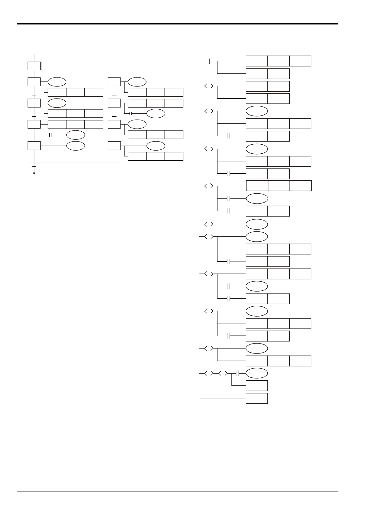
SFC Figure:
M1002
S0
S20
T0
S21
T1
S22
T2
S23
T13
S0
TMR T0 K350
TMR T1 K250
TMR T2 K50
M1013
Y0
Y2
Y2
Y1
T10
T11
T12
S30
S31
S32
S33
Y12
TMR T10 K250
TMR T11 K50
M1013
Y11
TMR T12 K50
TMR T13 K350
Y12
Y10
Ladder Diagram:
M1002
S0
S
S20
S
S21
S
S22
S
S23
S
S30
S
T0
T1
M1013
T2
ZRST S0 S127
SET S0
SET S20
SET S30
Y0
TMR T0
K350
SET S21
Y2
TMR T1
K250
SET S22
TMR T2
K50
Y2
SET S23
Y1
Y12
TMR T10
T10
K250
SET S31
S31
S
M1013
TMR T11
K50
Y12
T11
SET S32
S32
S
T12
Y11
TMR T12
K50
SET S33
S33
S
Y10
TMR T13 K350
S23SS33
T13
S
S0
RET
END
1-22
DVP-PLC Application Manual
Page 27
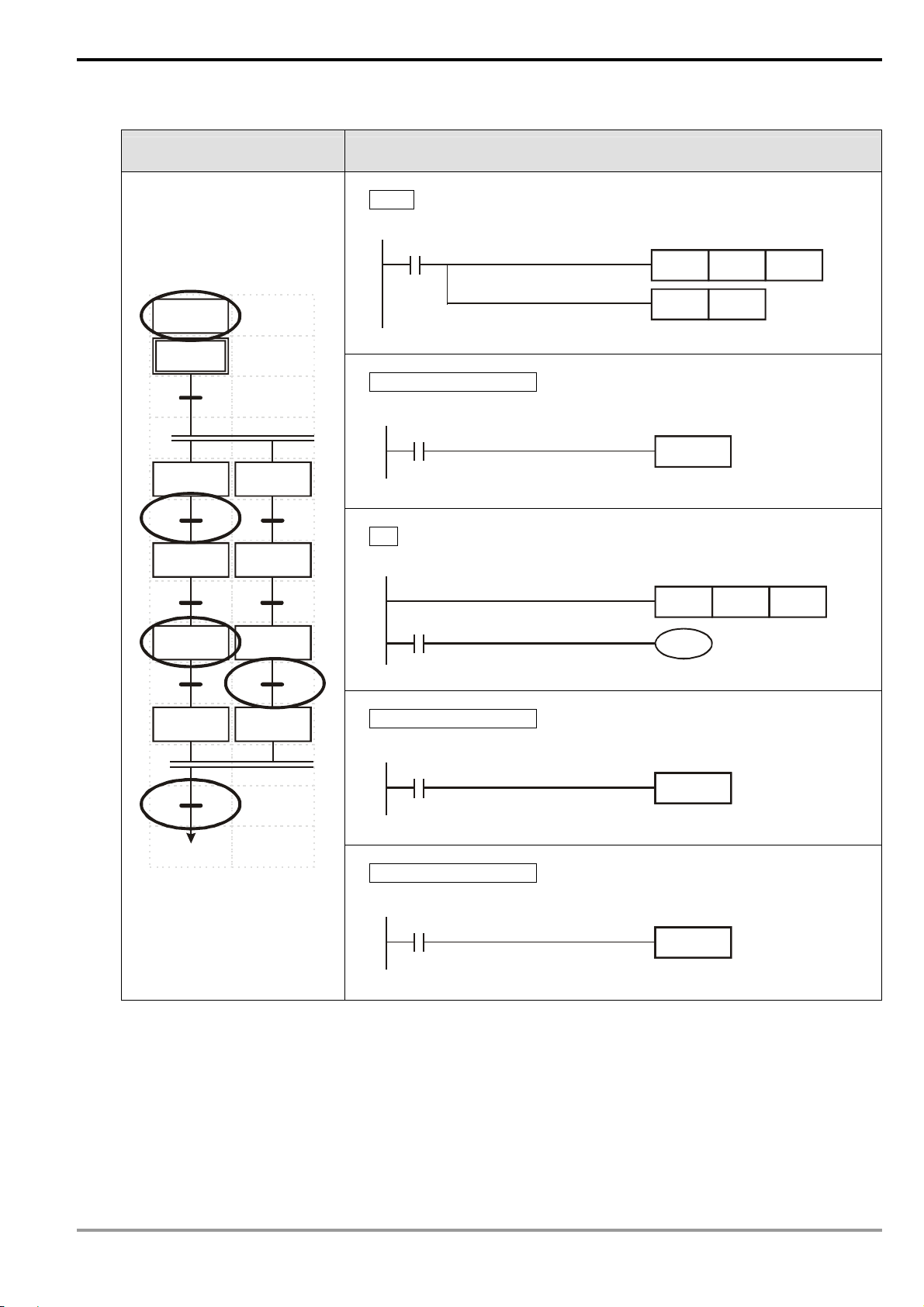
Drawing by SFC Editor (WPLSoft )
Drawn by SFC Internal Ladder Diagram
1 Basic Principles of PLC Ladder Diagram
LAD-0
M1002
S0ZRST S127
LAD-0
S0
0
S20
1
S21
2
S22
3
S23
S30
S31
S32
S33
S0SET
Transferring Condition 1
T0
TRANS*
5
6
7
S22
T2TMR K50
M1013
Y2
Transferring Condition 4
S0
T13
T13
T13
T13
T13
T13
T13
TRANS*
TRANS*
TRANS*
TRANS*
TRANS*
TRANS*
TRANS*
4
Transferring Condition 7
T12
T12
T12
T12
T12
T12
T12
TRANS*
TRANS*
TRANS*
TRANS*
TRANS*
TRANS*
TRANS*
DVP-PLC Application Manual
1-23
Page 28

1 Basic Principles of PLC Ladder Diagram
MEMO
1-24
DVP-PLC Application Manual
Page 29
2.1 All Devices in DVP-PLC
ES/EX/SS series MPU:
Device
Type
X External input relay X0 ~ X177, 128 points, octal
Y External output relay Y0 ~ Y177, 128 points, octal
General purpose
Auxiliary
M
relay
T Timer
Relay (bit)
C Counter
S Step
T Present value of timer T0 ~ T127, 128 points
C Present value of counter
Register (word data)
Pointer
Constant
* The latched area is fixed and cannot be changed.
Data
D
register
N For master control nested loop N0 ~ N7, 8 points
P For CJ, CALL instructions P0 ~ P63, 64 points
I Interruption
K Decimal form
H Hexadecimal form
Latched* M512 ~ M767, 256 points
Special purpose
100ms timer T0 ~ T63, 64 points
10ms timer (M1028 = On)
1ms timer T127, 1 points
16-bit counting up
(general purpose)
16-bit counting up (latched*) C112 ~ C127, 16 points
32-bit
counting
up/down
high-speed
counter
(latched*)
Initial step (latched*) S0 ~ S9, 10 points
Zero return (latched*)
Latched* S20 ~ S127, 108 points
Item Range Function
1-phase 1 input
1-phase 2 inputs C246, C247, C249, 3 points
2-phase 2 inputs C251, C252, C254, 3 points
General purpose D0 ~ D407, 408 points
Latched* D408 ~ D599, 192 points
Special purpose D1000 ~ D1311, 312 points
Index indication E, F, 2 points
External interruption I001, I101, I201, I301, 4 points
Timed interruption
Communication interruption I150, 1 point
2 Functions of Devices in DVP-PLC
Corresponds to external
To ta l
256 points
M0 ~ M511, M768 ~ M999, 744
points
M1000 ~ M1279, 280 points
(some are latched)
T64 ~ T126, 63 points (M1028
= Off: 100ms)
C0 ~ C111, 112 points
C235 ~ C238, C241, C242,
C244, 7 points
S10 ~ S19, 10 points (used with
IST instruction)
C0 ~ C127, 16-bit counter, 128 points
C235 ~ C254, 32-bit counter, 13 points
I6□□, 1 point (□□=10 ~ 99, time base =
1ms ) (for V5.7 and above)
K-32,768 ~ K32,767 (16-bit operation)
K-2,147,483,648 ~ K2,147,483,647 (32-bit operation)
H0000 ~ HFFFF (16-bit operation)
H00000000 ~ HFFFFFFFF (32-bit operation)
To ta l
1,280 points
Tota l
128 points
Tota l
128 points
Tota l
13 points
Tota l
128 points
To ta l
600 points
To ta l
312 points
input points
Corresponds to external
output points
The contact can be
On/Off in the program.
Timer indicated by TMR
instruction. If timing
reaches its target, the T
contact of the same No.
will be On.
Counter indicated by
CNT (DCNT) instruction.
If counting reaches its
target, the C contact of
the same No. will be On.
Used for SFC.
When the timing
reaches the target, the
contact of the timer will
be On.
When the counting
reaches the target, the
contact of the counter
will be On.
Memory area for data
storage; E, F can be
used for index
indication.
Control point for main
control loop
Position index for CJ
and CALL
Position index for
interruption subroutine.
DVP-PLC Application Manual
2-1
Page 30
SA/SX/SC series MPU:
Device
Type
X External input relay X0 ~ X177, 128 points, octal
Y External output relay Y0 ~ Y177, 128 points, octal
Auxiliary
M
Relay
T Timer
Relay (bit)
C Counter
S Step point
T Present value of timer T0 ~ T255, 256 points
C Present value of counter
Data
D
Register (word data)
register
N/A File register K0 ~ K1,599 (1,600 points) (*4)
2 Functions of Devices in DVP-PLC
Item Range Function
Corresponds to external
input points
Corresponds to external
output points
The contact can be
On/Off in the program.
Timer indicated by TMR
instruction. If timing
reaches its target, the T
contact of the same No.
will be On.
Counter indicated by
CNT (DCNT) instruction.
If counting reaches its
target, the C contact of
the same No. will be On.
Used for SFC.
When the timing
reaches the target, the
contact of the timer will
be On.
When the counting
reaches the target, the
contact of the counter
will be On.
Memory area for data
storage; E, F can be
used for index
indication.
Expanded register for
data storage.
General purpose M0 ~ M511, 512 points (*1)
Latched*
Special purpose
100ms
10ms
1ms
16-bit counting up
32-bit counting up/down
For SA/SX, 32-bit
high-speed counter
For SC, 32-bit high-speed
counter
Initial step S0 ~ S9, 10 points (*1)
Zero return
General purpose S20 ~ S511, 492 points (*1)
Latched* S512 ~ S895, 384 points (*3)
Alarm S896 ~ S1023, 128 points (*3)
General purpose D0 ~ D199, 200 points (*1)
Latched*
Special purpose D1000 ~ D1999, 1,000 points
Index indication E0 ~ E3, F0 ~ F3, 8 points (*1)
M512 ~ M999, 488 points (*3)
M2000 ~ M4095, 2,096 points (*3)
M1000 ~ M1999, 1,000 points
(some are latched)
T0 ~ T199, 200 points (*1)
T192 ~ T199 for subroutine
T250 ~ T255, 6 accumulative points
(*4)
T200 ~ T239, 40 points (*1)
T240 ~ T245, 6 accumulative points
(*4)
T246 ~ T249, 4 accumulative points
(*4)
C0 ~ C95, 96 points (*1)
C96 ~ C199, 104 points (*3)
C200 ~ C215, 16 points (*1)
C216 ~ C234, 19 points (*3)
C235 ~ C244, 1-phase 1 input, 9
points (*3)
C246 ~ C249, 1-phase 2 inputs, 3
points (*3)
C251 ~ C254, 2-phase 2 inputs, 4
points (*3)
C235 ~ C245, 1-phase 1 input, 11
points (*3)
C246 ~ C250, 1-phase 2 inputs, 4
points (*3)
C251 ~ C255, 2-phase 2 inputs, 4
points (*3)
S10 ~ S19, 10 points (used with IST
instruction) (*1)
C0 ~ C199, 16-bit counter, 200 points
C200 ~ C254, 32-bit counter, 50 points (SC: 53
points)
D200 ~ D999, 800 points (*3)
D2000 ~ D4999, 3,000 points (*3)
To ta l
256
points
To ta l
4,096
points
To ta l
256
points
To ta l
235
points
Tota l
16
points
To ta l
19
points
To ta l
1,024
points
To ta l
5,000
points
2-2
DVP-PLC Application Manual
Page 31

2 Functions of Devices in DVP-PLC
N For Master control loop N0 ~ N7, 8 points
P For CJ, CALL instructions P0 ~ P255, 256 points
External interruption I001, I101, I201, I301, I401, I501, total 6 points
Timed interruption
Pointer
Constant
*1. Non-latched area cannot be modified.
*2. The preset non-latched area can be modified into latched area by setting up parameters.
*3. The preset latched area can be modified into non-latched area by setting up parameters.
*4. The fixed latched area cannot be modified
Interruption
I
K Decimal form
H Hexadecimal form
Interruption inserted when
high-speed counter
reaches target
Communication interruption I150, 1 point
I6□□, I7□□, 2 points (□□ = 1 ~ 99, time
base = 1ms)
I010, I020, I030, I040, I050, I060, total 6 points
K-32,768 ~ K32,767 (16-bit operation)
K-2,147,483,648 ~ K2,147,483,647 (32-bit operation)
H0000 ~ HFFFF (16-bit operation)
H00000000 ~ HFFFFFFFF (32-bit operation)
Latched settings for all devices in SA/SX/SC series MPU:
General purpose Latched Special auxiliary relay Latched
M0 ~ M511 M512 ~ M999 M1000 ~ M1999 M2000 ~ M4095
M
(Auxiliary relay)
It is fixed to be non-latched
Default: latched Default: latched
Start: D1200 (K512)
End: D1201 (K999)
Some are latched and
cannot be modified
Control point for main
control loop
Position index for CJ
and CALL
Position index for
interruption subroutine.
Start: D1202 (K2,000)
End: D1203 (K4,095)
T
(Timer)
C
(Counter)
S
(Step relay)
D
(Register)
100 ms 10 ms 10 ms 1 ms 100 ms
T0 ~ T199 T200 ~ T239 T240 ~ T245 T246 ~ T249 T250 ~ T255
It is fixed to be non-latched It is fixed to be non-latched
16-bit counting up 32-bit counting up/down
C0 ~ C95 C96 ~ C199 C200 ~ C215 C216 ~ C234 C235 ~ C255
It is fixed to be
non-latched
Initial Zero return General purpose Latched Alarm step
S0 ~ S9 S10 ~ S19 S20 ~ S511 S512 ~ S895 S896 ~ S1023
It is fixed to be non-latched
General purpose Latched Special register Latched
D0 ~ D199 D200 ~ D999 D1000 ~ D1999 D2000 ~ D4999
It is fixed to be non-latched
Default: latched Default: latched Default: latched
Start: D1208 (K96)
End: D1209 (K199)
Start: D1216 (K200)
End: D1217 (K999)
It is fixed to be
non-latched
Default: latched Default: latched
Start: D1210 (K216)
End: D1211 (K234)
Default: latched
Start: D1214 (K512)
End: D1215 (K895)
Some are latched and
cannot be modified.
Accumulative type
It is fixed to be latched
32-bit high-speed counting
up/down
Start: D1212 (K235)
End: D1213 (K255)
It is fixed to be latched
Start: D1218 (K2,000)
End: D1219 (K4,999)
File Register
DVP-PLC Application Manual
K0 ~ K1599
It is fixed to be latched.
2-3
Page 32

EH/EH2/SV series MPU:
Device
Type
2 Functions of Devices in DVP-PLC
Item Range Function
X External input relay X0 ~ X377, 256 points, octal
Y External output relay Y0 ~ Y377, 256 points, octal
General purpose M0 ~ M499, 500 points (*2)
Auxiliary
M
relay
T Timer
Relay (bit)
C Counter
S Step
T Present value of timer T0 ~ T255, 256 points
C Present value of counter
Data
D
Register (word data)
Pointer
register
N/A File register K0 ~ K9,999 (10,000 points) (*4)
N For master control loop N0 ~ N7, 8 points
P For CJ, CALL instructions P0~P255, 256 points
I
Interruption
Latched
Special purpose M1000 ~ M1999, 1,000 points (some are latched)
100ms
10ms
1ms T246 ~ T249, 4 accumulative points (*4)
16-bit counting
up
32-bit counting
up/down
32-bit high-speed
counter
Initial step point S0 ~ S9, 10 points (*2)
Zero return
General purpose S20 ~ S499, 480 points (*2)
Latched S500 ~ S899, 400 points (*3)
Alarm S900 ~ S1023, 124 points (*3)
General purpose D0 ~ D199, 200 points, (*2)
Latched
Special purpose D1000 ~ D1999, 1,000 points
Index indication E0 ~ E7, F0 ~ F7, 16 points (*1)
External interruption
Timed interruption
Interruption inserted
when high-speed
counter reaches target
Pulse interruption I110, I120, I130, I140, 4 points
Communication
interrruption
M500 ~ M999, 500 points (*3)
M2000 ~ M4095, 2,096 points (*3)
T0 ~ T199, 200 points (*2)
T192 ~ T199 is for subroutine
T250~T255, 6 accumulative points (*4)
T200 ~ T239, 40 points (*2)
T240 ~ T245, 6 accumulative points (*4)
C0 ~ C99, 100 points (*2)
C100 ~ C199, 100 points (*3)
C200 ~ C219, 20 points (*2)
C220 ~ C234, 15 points (*3)
C235 ~ C244, 1-phase 1 input, 10 points (*3)
C246 ~ C249, 1-phase 2 inputs, 4 points(*3)
C251 ~ C254, 2-phases 2 inputs, 4 points (*3)
S10 ~ S19, 10 points (used with IST instruction)
(*2)
C0 ~ C199, 16-bit counter, 200 points
C200 ~ C254, 32-bit counter, 53 points
D200 ~ D999, 800 points (*3)
D2000 ~ D9999, 8,000 points (*3)
I00□(X0), I10□(X1), I20□(X2), I30□(X3), I40□(X4),
I50□(X5), 6 points (□ = 1, rising-edge trigger
0, falling-edge trigger
I6□□, I7□□, 2 points(□□ = 1~99ms) time base = 1ms
I8□□, 1 point (□□ = 1~99, time base = 0.1ms)
I010, I020, I030, I040, I050, I060, 6 points
I150, I160, I170, 3 points
Corresponds to external
To ta l
input points
512
points
4,096
points
points
points
1,024
points
10,000
points
, □ =
)
Corresponds to external
output points
To ta l
The contact can be
On/Off in the program.
Timer indicated by TMR
To ta l
instruction. If timing
reaches its target, the T
256
contact of the same No.
will be On.
Counter indicated by
CNT (DCNT)
To ta l
instruction. If counting
253
reaches its target, the C
contact of the same No.
will be On.
To ta l
Used for SFC.
When the timing
reaches the target, the
contact of the timer will
be On.
When the counting
reaches the target, the
contact of the counter
will be On.
Memory area for data
To ta l
storage; E, F can be
used for index
indication.
Expanded register for
data storage.
Control point for main
control loop
Position index for CJ
and CALL
Position index for
interruption subroutine.
2-4
DVP-PLC Application Manual
Page 33

2 Functions of Devices in DVP-PLC
Device
Type
K Decimal form
H Hexadecimal form
Constant
*1. Non-latched area cannot be modified.
*2. The preset non-latched area can be modified into latched area by setting up parameters.
*3. The preset latched area can be modified into non-latched area by setting up parameters.
*4. The fixed latched area cannot be modified
Latched settings for all devices in EH/EH2/SV series MPU:
M
(Auxiliary relay)
T
(Timer)
C
(Counter)
S
(Step relay)
D
(Register)
File register
*1: K-1 refers to the default setting is non-latched.
Item Range Function
Frequency
measurement card
interruption
General purpose Latched Special auxiliary relay Latched
M0 ~ M499 M500 ~ M999 M1000 ~ M1999 M2000 ~ M4095
Start: D1200 (K500)
End: D1201 (K999)
100 ms 10 ms 10 ms 1 ms 100 ms
T0 ~ T199 T200 ~ T239 T240 ~ T245 T246 ~ T249 T250 ~ T255
Default: non-latched Default: non-latched
Start: D1204 (K-1)*1
End: D1205 (K-1)*1
16-bit counting up 32-bit counting up/down 32-bit high-speed counting up/down
C0 ~ C99 C100 ~ C199 C200 ~ C219 C220 ~ C234 C235 ~ C245 C246 ~ C255
Default:
non-latched
Start: D1208 (K100)
End: D1209 (K199)
Initial Zero return
S0 ~ S9 S10 ~ S19 S20 ~ S499 S500 ~ S899 S900 ~ S1023
Non-latched (default) Latched (default)
General purpose Latched Special register Latched
D0 ~ D199 D200 ~ D999 D1000 ~ D1999 D2000 ~ D9999
Default: non-latched Default: latched Default: latched
Start: D1216 (K200)
End: D1217 (K999)
I180, 1 point
K-32,768 ~ K32,767 (16-bit operation)
K-2,147,483,648 ~ K2,147,483,647 (32-bit operation)
H0000 ~ HFFFF (16-bit operation)
H00000000 ~ HFFFFFFFF (32-bit operation)
Some are latched and
cannot be modified.
Start: D1206 (K-1)*1
End: D1207 (K-1)*1
Default: latched
Start: D1214 (K500)
End: D1215 (K899)
Default:
non-latched
Start: D1210 (K220)
End: D1211 (K234)
General
purpose
K0 ~ K9,999
It is fixed to be latched.
Default: latched Default: latched
Latched Step alarm
Some is latched and
cannot be modified.
It is fixed to be latched.
Start: D1202 (K2,000)
End: D1203 (K4,095)
Accumulative type
Start: D1212 (K235)
End: D1213 (K255)
It is fixed to be latched.
Start: D1218 (K2,000)
End: D1219 (K9,999)
Power On/Off or the MPU switches between RUN/STOP:
Memory of ES/EX/SS V5.5 (and above)
Memory type
Non-latched Clear
Latched Unchanged Unchanged Clear Unchanged
Special M,
Special D,
index register
Power
Off→On
Initial Unchanged Unchanged Initial setting
STOP→RUN RUN→STOP
Clear when M1033 = Off
Remain unchanged when M1033 = On
Clear all non-latched
areas (M1031)
Clear Unchanged 0
Clear all latched
areas (M1032)
Default
setting
Memory of SA/SX/SC/EH/EH2/SV series MPU:
DVP-PLC Application Manual
2-5
Page 34

2 Functions of Devices in DVP-PLC
Memory type
Non-latched Clear Unchanged
Latched Unchanged Unchanged Clear 0
Special M,
Special D,
index register
File Register Unchanged 0
Power
Off→On
Initial Unchanged Unchanged
STOP→RUN RUN→STOP
Clear when M1033 = Off
Remain unchanged when
M1033 = On
Clear all non-latched
area (M1031)
Clear Unchanged 0
Clear all latched
area (M1032)
Default
setting
Initial
setting
2.2 Values, Constants [K] / [H]
K Decimal form
Constant
H Hexadecimal form
For different control purposes, there are five types of values inside DVP-PLC for executing the operations. See
the explanations bellows for the functions and works of every type of value.
1. Binary value (BIN)
K-32,768 ~ K32,767 (16-bit operation)
K-2,147,483,648 ~ K2,147,483,647 (32-bit operation)
H0 ~ HFFFF (16-bit operation)
H0 ~ HFFFFFFFF (32-bit operation)
All the operations and storage of values in PLC are conducted in BIN. Belows are the terms for BIN values.
Bit:
Nibble:
The basic unit for a BIN value, either 1 or 0.
Composed of 4 continuous bits (e.g. b3 ~ b0). Presented as the decimal value 0 ~ 9 of a digit
or 0 ~ F in hex.
Byte:
Word:
Composed of 2 continuous nibble (i.e. 8 bits, b7 ~ b0). Presented as 00 ~ FF in hex.
Composed of 2 continuous bytes (i.e. 16 bits, b15 ~ b0). Presented as 4-digit 0000 ~ FFFF in
hex.
Double word:
Composed of 2 continuous words (i.e. 32 bits, b31 ~ b0). Presented as 8 digit 00000000 ~
FFFFFFFF.
Bit, nibble, byte, word, and double word in a binary system:
DW
W1
BY3 BY2 BY1 BY0
W0
Double Word
Word
Byte
2. Octal value (OCT)
The No. of external input and output terminals in DVP-PLC is numbered in octal system.
For example:
External input: X0 ~ X7, X10 ~ X17…(device No.)
2-6
NB0NB1NB2NB3NB4NB5NB6NB7
Nibble
Bit
DVP-PLC Application Manual
Page 35

2 Functions of Devices in DVP-PLC
External output: Y0 ~ Y7, Y10 ~ Y17…(device No.)
3. Decimal value (DEC)
Occassions of using decimal values in DVP-PLC:
Set value in timer T and counter C, e.g. TMR C0 K50 (constant K)
No. of device S, M, T, C, D, E, F, P, I, e.g. M10, T30. (device No.)
Operands in application instructions, e.g. MOV K123 D0 (constant K)
4. Binary code decimal (BCD)
A decimal datum is presented by a nibble or 4 bits. Therefore, a continuous 16 bits can be presented as a 4-digit
decimal value. BCD is mainly used on reading the input value from the DIP switch or the data output to a 7-section
display.
5. Hexadecimal value (HEX)
Occassion of using hexadecimal values:
Operands in application instructions, e.g. MOV H1A2B D0 (constant H)
Constant K:
“K” is normally placed before a decimal value in the PLC. For example, K100 refers to a decimal value, 100.
Exception:
K and bit devices X, Y, M and S can combine into data in bit, byte, word or double word, e.g. K2Y10, K4M100.
Here K1 refers to a 4-bit data and K2 ~ K4 refer to 8-bit, 12-bit and 16-bit data.
Constant H:
“H” is normally placed before a hexadecimal value in the PLC. For example, H100 refers to a hexadecimal value,
100.
Reference table:
Binary
(BIN)
For PLC internal operation
0000 0000 0 0 0 0 0 0 0 0 0 0 0
0000 0001 1 1 0 0 0 0 0 0 0 1 1
0000 0010 2 2 0 0 0 0 0 0 1 0 2
0000 0011 3 3 0 0 0 0 0 0 11 3
0000 0100 4 4 0 0 0 0 0 1 0 0 4
0000 0101 5 5 0 0 0 0 0 1 0 1 5
0000 0110 6 6 0 0 0 0 0 11 0 6
0000 0111 7 7 0 0 0 0 0 1 1 1 7
0000 1000 10 8 00 0 0 1 0 0 0 8
0000 1001 11 9 0 0 0 0 1 0 0 1 9
0000 1010 12 10 0 0 0 1 0 0 0 0 A
0000 1011 13 11 0 0 0 1 0 0 0 1 B
0000 1100 14 12 0 0 0 1 0 0 1 0 C
0000 1101 15 13 0 0 0 1 0 0 1 1 D
0000 1110 16 14 0 0 0 1 0 1 0 0 E
0000 1111 17 15 0 0 0 1 0 1 0 1 F
0001 0000 20 16 0 0 0 1 0 1 1 0 10
Octal
(OCT)
No. of device
X, Y
Decimal
(DEC)
Constant K,
No. of device M, S, T, C,
D, E, F, P, I
Binary Code Decimal
(BCD)
For DIP switch and 7-section
display
Hexadecimal
Constant H
(HEX)
DVP-PLC Application Manual
2-7
Page 36

2 Functions of Devices in DVP-PLC
Binary
(BIN)
For PLC internal operation
0001 0001 21 17 0 0 0 1 0 1 1 1 11
:
:
:
0 1 1 0 0 0 1 1 143 99 1 0 0 1 1 0 0 1 63
Octal
(OCT)
No. of device
X, Y
:
:
:
Decimal
(DEC)
Constant K,
No. of device M, S, T, C,
D, E, F, P, I
:
:
:
Binary Code Decimal
(BCD)
For DIP switch and 7-section
display
:
:
:
Hexadecimal
(HEX)
Constant H
:
:
:
2.3 Numbering and Functions of External Input/Output Contacts [X] / [Y]
No. of input/output contacts (in octal):
The No. of input and output contacts on the PLC MPU starts from X0 and Y0. The range of the No. varies upon
the number of points on the MPU. For I/O extension units, the No. of input and output contacts is calculated according
to its connection sequence with the MPU.
ES/EX/SS series MPU:
Model DVP-14ES DVP-14SS DVP-20EX DVP-24ES DVP-32ES DVP-40ES DVP-60ES I/O Extension Unit
Input X
Output Y
Note: The input points on I/O extension units start from X20 and output points from Y20, except input points on
DVP-40ES start from X30 and output from Y20; input points on DVP-60ES start from X50 and output from Y30. The No. of
input/output points on the I/O extension units increases by 8’s multiple. If the number of points is less than 8, it will be
counted as 8.
X0 ~ X7
(8 points)
Y0 ~ Y5
(6 points)
X0 ~ X7
(8 points)
Y0 ~ Y5
(6 points)
X0 ~ X7
(8 points)
Y0 ~ Y5
(6 points)
X0 ~ X17
(16 points)
Y0 ~ Y7
(8 points)
X0 ~ X17
(16 points)
Y0 ~ Y17
(16 points)
X0 ~ X27
(24 points)
Y0 ~ Y17
(16 points)
X0 ~ X43
(36 points)
Y0 ~ Y27
(24 points)
X20/30/50 ~ X177
(Note)
Y20/30 ~ Y177
(Note)
SA/SX/SC serues MPU:
Model DVP-10SX (Note1) DVP-12SA DVP-12SC I/O Extension Unit (Note 2)
Input X X0 ~ X3 (4 points) X0 ~ X7 (8 points) X0 ~ X5, X10 ~ X11 (8 points) X20 ~ X177
Output Y Y0 ~ Y1 (2 points) Y0 ~ Y3 (4 points) Y0 ~ Y1, Y10 ~ Y11 (4 points) Y20 ~ Y177
Note 1: Besides 4DI and 2DO, SX series MPU has also 2AI (12-bit) and 2AO (12-bit) of analog input/output.
Note 2: SX/SA/SC series MPU share the extension units with SS series MPU. The input points on I/O extension units start
from X20 and output points start from Y20. The calculation on the No. of I/O points is the same as that in SS series.
EH series MPU:
Model DVP-16EH
Input X
X0 ~ X7
(8 points)
DVP-20EH
(Note 1)
X0 ~ X13
(12 points)
DVP-32EH
(Note1, 2)
X0 ~ X17
(16 points)
DVP-40EH DVP-48EH DVP-64EH DVP-80EH
X0 ~ X27
(24 points)
X0 ~ X27
(24 points)
X0 ~ X37
(32 points)
X0 ~ X47
(40 points)
Extension
Unit (Note 3)
X※~X377
I/O
Output Y
Note 1: The output type of 20EH00T and 32EH00T is transistor, among which Y0 and Y2 are high-speed transistor output
(200KHz) and other outputs are normal transistor output (10KHz). The output type of other MPUs with 16/48/64/80 points is
transistor and all outputs are normal transistor output (10KHz).
Note 2: The terminal layouts of 32EH00T, 32EH00R and 32EH00M are different. See the instruction sheets of EH series
MPU. In 32EH00M, CH0 (Y0, Y1) and CH1 (Y2, Y3) are high-speed differential output.
Note 3: The start No. of the input and output points on the I/O extension unit resumes from the last No. in the MPU. The start
No. of input points on the I/O extension unit of DVP-16EH and DVP-20EH start from X20 and output points start from Y20.
The No. on the I/O extension unit are in sequence, with max. input point No. X377 and max. output point No. Y377.
Y0 ~ Y7
(8 points)
2-8
Y0 ~ Y7
(8 points)
Y0 ~ Y17
(16 points)
Y0 ~ Y17
(16 points)
Y0 ~ Y27
(24 points)
Y0 ~ Y37
(32 points)
Y0 ~ Y47
(40 points)
DVP-PLC Application Manual
Y※~Y377
Page 37

EH2 series MPU:
2 Functions of Devices in DVP-PLC
Model DVP-16EH2
Input X
Output Y
Note 1: The output type of 20EH00T2 and 32EH00T2 is transistor, among which Y0 and Y2 are high-speed transistor output
(200KHz) and other outputs are normal transistor output (10KHz). The output type of other MPUs with 16/48/64/80 points is
transistor and all outputs are normal transistor output (10KHz).
Note 2: The output type of 40EH00T2 is transistor, among which CH0 (Y0, Y1), CH1 (Y2, Y3), CH2 (Y4) and CH3 (Y6) are
high-speed transistor output (200KHz). The output type of other output points is normal transistor output (10KHz).
Note 3: The numbering of the I/O points on EH2 series MPU is the same as that of EH series MPU.
X0 ~ X7
(8 points)
Y0 ~ Y7
(8 points)
DVP-20EH2
(Note 1)
X0 ~ X13
(12 points)
Y0 ~ Y7
(8 points)
DVP-32EH2
(Note1)
X0 ~ X17
(16 points)
Y0 ~ Y17
(16 points)
DVP-40EH2
(Note 2)
X0 ~ X27
(24 points)
Y0 ~ Y17
(16 points)
DVP-48EH2 DVP-64EH2 DVP-80EH2
X0 ~ X27
(24 points)
Y0 ~ Y27
(24 points)
X0 ~ X37
(32 points)
Y0 ~ Y37
(32 points)
X0 ~ X47
(40 points)
Y0 ~ Y47
(40 points)
I/O Extension
Unit (Note 3)
X※~X377
Y※~Y377
SV series MPU:
Model DVP-28SV (Note 1) I/O Extension Unit (Note 2)
Input X X0 ~ X17 (16 points) X20 ~ X377
Output Y Y0 ~ Y13 (12 points) Y20 ~ Y377
Note 1: The output type of 28SV11T is transistor output, among which CH0 (Y0, Y1), CH1 (Y2, Y3), CH2 (Y4) and CH3 (Y6)
are high-speed transistor output (200KHz); others are normal transistor output (10KHz).
Note 2: The input points on I/O extension units start from X20 and output points start from Y20. The calculation on the No. of
I/O points is the same as that in SS series.
Input Relay X0 ~ X377
The numbering of input relays (or input terminals) is in octal form. EH series MPU can have up to 256
points and the range is: X0 ~ X7, X10 ~ X17, …, X370 ~ X377.
Output Relay Y0 ~ Y377
The numbering of output relays (or output terminals) is also in octal form. EH series MPU can have up to
256 points and the range is: Y0 ~ Y7, Y10 ~ Y17, …, Y370 ~ Y377.
Functions of input contact X
The input contact X is connected to the input device and reads the input signals into the PLC. There is no
limitation on the times of using contact A or B of input contact X in the program. On/Off of the input contact X
only changes with On/Off of the input device. You cannot use the peripheral devices (HPP or WPLSoft) to force
On/Off of the input contact X.
The special relay M1304 in SA/SX/SC/EH series MPU allows the peripheral devices HPP or WPLSoft to
force On/Off of the input contact X, but the PLC will not be able to receive external input signals at this time.
Functions of output contact Y
Output contact Y sends out On/Off signals to drive the load connected to output contact Y. There are two
types of output contacts, relay and transistor. Thereis no limitation on the times of using contact A or B of output
contact Y in the program, but the No. of output coil Y can only be used once in the program; otherwise
according to the scan principle of the PLC program, the output status will be determined by the circuit of the last
output Y in the program.
DVP-PLC Application Manual
2-9
Page 38

2 Functions of Devices in DVP-PLC
X0
Y0
1
The output of Y0 will be determined by circuit 2, i.e. On/Off of X10 will
determine the output status of Y0.
Y0 is repeated
X10
Y0
2
The Handling Process of PLC Program (Batch I/O)
Regenerate input signal
Progr a m proce ssing
Regenerat e out p ut
X input
Input terminal
Read into memory
Input signal memory
Read X0 status from memory
X0
Read Y0 status from memory
Y0
Write in Y0 status
Y0
M0
Write in M0 status
Output latched memory
Output
Regenerate input signal
1. Before the execution of the program, PLC reads the
On/Off status of the external input signals into the
input signal memory at a time.
2. The On/Off status of the input signal during the
execution of the program will not change the signal
Device Memory
status in the input signal memory. The new On/Off
status will be read in in the next scan.
3. There will be approximately a 10ms delay from the
On→Off or Off→On changes to the status being
recognized by the contact in the program. The delay
time may be affected by the scan time in the
program.
Output terminal
Y output
Program processing
After the PLC reads the On/Off status of every input
signal in the input signal memory, it will start to execute
every instruction in the program in order starting from
address 0. The execution result (On/Off of every output
coil) will be stored in order into the device memory.
Regenerate output
1. When the program executes to END instruction, it
will send the On/Off status of Y in the device memory
to the output latched memory. The output latched
memory is the coil of the output relay.
2. There will be a 10ms delay from OnÆOff or OffÆOn
of the relay coil to the On/Off status of the contact.
3. There will be a 10 ~ 20us delay from OnÆOff or
OffÆOn of the transistor module to the On/Off status
of the contact.
2-10
DVP-PLC Application Manual
Page 39

2 Functions of Devices in DVP-PLC
2.4 Numbering and Functions of Auxiliary Relays [M]
No. of auxiliary relays (in decimal)
ES/EX/SS series MPU:
General purpose M0 ~ M511, M768 ~ M999, 744 points. Fixed to be non-latched.
Auxiliary relay M
SA/SX/SC series MPU:
Latched M512 ~ M767, 256 points. Fixed to be latched.
Special purpose M1000 ~ M1279, 280 points. Some are latched.
General purpose M0 ~ M511, 512 points. Fixed to be non-latched.
Total 1,280
points
Auxiliary relay M
Latched
Special purpose M1000 ~ M1999, 1000 points. Some are latched.
M512 ~ M999, M2000 ~ M4095, 2,584 points. Can be modified to be
non-latched by setting up parameters.
Total 4,096
points
EH/EH2/SV series MPU:
M0 ~ M499, 500 points. Can be modified to be latched by setting up
parameters.
M500 ~ M999, M2000 ~ M4095, 2,596 points. Can be modified to be
non-latched by setting up parameters.
Total 4,096
points
Auxiliary relay M
General purpose
Latched
Special purpose M1000 ~ M1999, 1,000 points. Some are latched.
Functions of auxiliary relays:
Both auxiliary relay M and output relay Y have output coils and contact A, B, and there is no limitation on the
times of using the contact. You can use auxiliary relay M to assemble a control loop, but it cannot directly drive the
external load. There are three types of auxiliary relays:
1. General purpose auxiliary relay: If the relay encouters power cut during the operation of the PLC, its status will
be reset to Off and stay Off when the power is on again.
2. Latched auxiliary relay: If the relay encounters power cut during the operation of the PLC, its status will be
retained and stay at the status before the power cut when the power is on again.
3. Special purpose auxiliary relay: Every relay of this kind has its specific function. Do not use undefined special
purpose auxiliary relay. See 2.10 for special puspose auxiliary relay of all series MPU and 2.11 for its functions.
2.5 Numbering and Functions of Step Relays [S]
No. of step relays (in decimal)
ES/EX/SS series MPU:
Initial latched S0 ~ S9, 10 points. Fixed to be latched.
Step relay S
Zero return
latched
Latched S20 ~ S127, 108 points. Fixed to be latched.
SA/SX/SC series MPU:
Initial S0 ~ S9, 10 points. Fixed to be non-latched.
Zero return S10 ~ S19, 10 points, used with IST instruction. Fixed to be non-latched.
Step relay S
General purpose S20 ~ S511, 492 points. Fixed to be non-latched.
Latched
Alarm S896 ~ S1023, 128 points. Fixed to be latched.
DVP-PLC Application Manual
S10 ~ S19, 10 points, used with IST instruction. Fixed to be latched.
S512 ~ S895, 384 points. Can be modified to be non-latched by setting
up parameters.
Total 128
points
To ta l
1,024 points
2-11
Page 40

EH/EH2/SV series MPU:
Initial
2 Functions of Devices in DVP-PLC
S0 ~ S9, 10 points. Can be modified to be latched by setting up
parameters.
Zero return
Step relay S
General purpose
Latched
Alarm
S10 ~ S19, 10 points, used with IST instruction. Can be modified to be
latched by setting up parameters.
S20 ~ S499, 480 points. Can be modified to be latched by setting up
parameters.
S500 ~ S899, 400 points. Can be modified to be non-latched by setting
up parameters.
S900 ~ S1023, 124 points. Can be modified to be latched by setting up
parameters.
To ta l
1,024 points
Functions of step relays:
The step relay S can easily set up the procedure in the industrial automation, which is the most basic device in
the the sequential function chart (SFC) and has to be used with STL, RET instructions.
The device No. of S is S0 ~ S1023 (total 1,024 points) and both step relay S and output relay Y have output coils
and contact A, B, and there is no limitation on the times of using the contact. S cannot directly drive the external load.
When the step relay is not used in SFC, it can be used as a normal auxiliary relay. There are four types of step relays:
1. Initial step relay: S0 ~ S9, total 10 points, used for initial steps.
2. Zero return step relay: S10 ~ S19, total 10 points. S10 ~ S19 are planned for zero return when used with API 60
IST instruction in the program. If they are not used with IST, they will become normal step relays.
3. General purpose step relay: S20 ~ S511, total 492 points (for SA/SX/SC series MPU); S20 ~ S499, total 480
points (for EH/EH2/SV series MPU). Used for general purposes in SFC and their status will all be cleared when
the operation of the PLC encounters power cut.
4. Latched step relay: S512 ~ S895, total 384 points (for SA/SX/SC series MPU); S20 ~ S127, total 108 points (for
ES/EX/SS series MPU); S500 ~ S899, total 400 points (for EH/EH2/SV series MPU). Used for latched function in
SFC and their status will all be retained when the operation of the PLC encounters power cut. They will remain at
the status before the power cut when the PLC is powered again.
5. Alarm step relay: S896 ~ S1023, total 128 points (for SA/SX/SC series MPU); S900 ~ S1023, total 124 points
(for EH/EH2/SV series MPU). Used with alarm driving instruction API 46 ANS as an alarm contact for recording
the alarm messages or eliminating external malfunctions.
2.6 Numbering and Functions of Timers [T]
No. of timers (in decimal)
ES/EX/SS series MPU:
100ms general purpose T0 ~ T63, 64 points
2-12
Timer T
10ms general purpose T64 ~ T126, 63 points (M1028 = On:10ms; M1028 = Off:100ms)
1ms general purpose T127, 1 point
DVP-PLC Application Manual
Tota l
128 points
Page 41

2 Functions of Devices in DVP-PLC
SA/SX/SC series MPU:
100ms general purpose
Time T
100ms accumulative T250 ~ T255, 6 points. Fixed to be latched.
10ms general purpose T200 ~ T239, 40 points. Fixed to be non-latched
10ms accumulative T240 ~ T245, 6 points. Fixed to be latched.
1ms accumulative T246 ~ T249, 4 points. Fixed to be latched.
EH/EH2/SV series MPU:
100ms general purpose
Timer T
100ms accumulative T250 ~ T255, 6 points. Fixed to be latched.
10ms general purpose T200 ~ T239, 40 points. Can be latched by setting up parameters.
10ms accumulative T240 ~ T245, 6 points. Fixed to be latched.
1ms accumulative T246 ~ T249, 4 points. Fixed to be latched.
Functions of timers:
The units of the timer are 1ms, 10ms and 100ms and the counting method is counting up. When the present
value in the timer equals the set value, the output coil will be On. The set value should be a K value in decimal and the
data register D can also be a set value.
T0 ~ T199, 200 points. T192 ~ T199 are the timers for subroutine. Fixed to
be non-latched
To ta l
256 points
T0 ~ T199, 200 points. Can be latched by setting up parameters.
T192 ~ T199 are the timers for subroutine.
To ta l
256 points
The actual set time in the timer = timing unit × set value
There are three types of timers:
1. General purpose timer:
For ES/SA series MPU: The timer executes once when the program reaches END instruction. When TMR
instruction is executed, the output coil will be On when the timing reaches its target.
For EH/EH2/SV series MPU: The timer executes once when the program reaches TMR instruction. When TMR
instruction is executed, the output coil will be On when the timing reaches its target.
X0
TMR T0 K100
When X0 = On, The PV in timer T0 will count up by
100ms. When the PV = SV K100, the output coil T0
X0
T0
T0
Y0
10 secs
SV K100
PV
will be On.
When X0 = Off or the power is off, the PV in timer T0
will be cleared as 0, and the output coil T0 will be
Off.
Y0
2. Accumulative type timer:
For ES/SA series MPU: The timer executes once when the program reaches END instruction. When TMR
instruction is executed, the output coil will be On when the timing reaches its target.
For EH/EH2/SV series MPU: The timer executes once when the program reaches TMR instruction. When TMR
instruction is executed, the output coil will be On when the timing reaches its target.
DVP-PLC Application Manual
2-13
Page 42

2 Functions of Devices in DVP-PLC
X0
T250
TMR
Y0
T250 K100
When X0 = On, The PV in timer T250 will count up
by 100ms. When the PV = SV K100, the output coil
T0 will be On.
When X0 = Off or the power is off, timer T250 will
T2
T1+T2=10sec
SV K100
temporarily stop the timing and the PV remain
unchanged. When X0 is On again, the timing will
resume and the PV will count up and when the PV =
SV K100, the output coil T0 will be On.
X0
T250
Y0
T1
PV
3. Subrountine timer:
Timer T192 ~ T199 are used in subrountines or interruption subroutines.
For SA series MPU: The timer executes once when the program reaches END instruction. When END instruction
is executed, the output coil will be On when the timing reaches its target.
For EH/EH2/SV series MPU: The timer executes once when the program reaches TMR or END instruction. When
TMR or END instruction is executed, the output coil will be On when the PV equals SV.
If the general purpose timer is used in a subroutine or interruption subroutine but the subroutine is not being
executed, the timer will not be able to time correctly.
How to designate SV: The actual set time in the timer = timing unit × set value
a) Designating constant K: SV is a constant K
b) Indirectly designating D: SV is data register D
2.7 Numbering and Functions of Counters [C]
No. of counters (in decimal)
ES/EX/SS series MPU:
Counter C
32-bit counting up/down
high-speed counter C
16-bit counting up, for
general purpose
16-bit counting up, for
latched
1-phase 1 input
1-phase 2 inputs C246, C247, C249, 3 points. Fixed to be latched.
2-phase 2 inputs C251, C252, C254, 3 points. Fixed to be latched.
C0 ~ C111, 112 points. Fixed to be non-latched.
C112 ~ C127, 16 points. Fixed to be latched.
C235 ~ C238, C241, C242, C244, 7 points. Fixed to be
latched.
To ta l
141 points
SA/SX/SC series MPU:
Counter C
2-14
16-bit counting up, for
general purpose
16-bit counting up, for
latched
32-bit counting
up/down, for general
purpose
32-bit counting
up/down, for latched
C0 ~ C95, 96 points. Fixed to be non-latched.
C96 ~ C199, 104 points. Can be modified to be non-latched
by setting up parameters.
C200 ~ C215, 16 points. Fixed to be non-latched.
C216 ~ C234, 19 points. Can be modified to be non-latched
by setting up parameters.
DVP-PLC Application Manual
To ta l
235 points
Page 43

2 Functions of Devices in DVP-PLC
(SA/SX) 32-bit counting
up/down high-speed
counter C
(SC) 32-bit counting
up/down high-speed
counter C
EH/EH2/SV series MPU:
Counter C
32-bit counting up/down
high-speed counter C
1-phase 1 input, for
latched
1-phase 2 inputs, for
latched
2-phase 2 inputs, for
latched
1-phase 1 input, for
latched
1-phase 2 inputs, for
latched
2-phase 2 inputs, for
latched
16-bit counting up, for
general purpose
16-bit counting up, for
latched
32-bit counting
up/down, for general
purpose
32-bit counting
up/down, for latched
Software 1-phase 1
input
Hardware 1-phase 1
input
Hardware 1-phase 2
inputs
Hardware 2-phase 2
inputs
C235 ~ C242, C244, 9 points
C246, C247, C249, 3 points
C251 ~ C254, 4 points
C235 ~ C245, 11 points
C246 ~ C250, 4 points
C251 ~ C255, 4 points
C0 ~ C99, 100 points. Can be modified to be latched by
setting up parameters.
C100 ~ C199, 100 points. Can be modified to be non-latched
area by setting up parameters.
C200 ~ C219, 20 points. Can be modified to be latched by
setting up parameters.
C220 ~ C234, 15 points. Can be modified to be non-latched
by setting up parameters.
C235 ~ C240, 6 points
C241 ~ C244, 4 points
C246 ~ C249, 4 points
C251 ~ C254, 4 points
Can be modified to be
non-latched by setting up
parameters.
Can be modified to be
non-latched by setting up
parameters.
Total 16
points
Total 19
points
To ta l
253 points
Features of counter:
16 bits counters 32 bits counters
Type General purpose General purpose High speed
Counting direction Counting up Counting up, counting down
Set value 0 ~ 32,767 -2,147,483,648 ~ +2,147,483,647
SV designation Constant K or data register D Constant K or data register D (designating 2 values)
Present value
Output contact
Reset PV will be return to 0 when RST instruction is executed and the contact will be reset to Off.
Contact action Acts when the scanning is completed.
Counting will stop when the SV is
reached.
On and being retained when the
counting reaches SV.
Counter will continue when the SV is reached.
On and keeps being On when counting up reaches SV.
Reset to Off when counting down reaches SV.
Acts immediately when the
Acts when the scanning is
completed.
counting reaches its target,
has nothing to do with the scan
period.
Functions of counters:
When the pulse input signals of the counter go from Off to On and the present value in the counter equals the
set value, the output coil will be On. The set value should be a K value in decimal and the data register D can also be
a set value.
16-bit counters C0 ~ C199:
1. The setup range of 16-bit counter: K0 ~ K32,767. K0 is the same as K1. The output contact will be On
immediately when the first counting starts.
2. PV in the general purpose counter will be cleared when the power of the PLC is switched off. If the counter is a
latched type, the counter will retain the PV and contact status before the power is off and resume the counting
DVP-PLC Application Manual
2-15
Page 44

2 Functions of Devices in DVP-PLC
after the power is on again.
3. If you use MOV instruction, WPLSoft or HPP to send a value bigger than the SV to the present value register of
C0, next time when X1 goes from Off to On, the contact of counter C0 will be On and its PV will equal SV.
4. The SV in the counter can be constant K (set up directly) or the values in register D (set up indirectly, excluding
special data registers D1000~ D1999).
5. If you set up a constant K as the SV, it should be a positive value. Data register D as SV can be positive or
negative. When the PV reaches up to 32,767, the next PV will turn to -32,768.
Example:
LD X0
RST C0
LD X1
CNT C0 K5
LD C0
OUT Y0
a) When X0 = On, RST instruction will be
executed, PV in C0 will be “0” and the
output contact will be reset to Off.
b) When X1 goes from Off to On, the PV in
the counter will count up (plus 1).
c) When the counting of C0 reaches SV K5,
the contact of C0 will be On and PV of C0
= SV = K5. The X1 trigger signal comes
afterwards will not be accepted by C0 and
the PV of C0 will stay at K5.
X0
X1
C0
X0
X1
PV in C0
0
Contacts Y0, C0
Y0
C0RST
C0 K5CNT
5
4
3
2
1
SV
0
32-bit general purpose addition/subtraction counters C200 ~ C234:
1. The setup range of 32-bit counter: K-2,147,483,648 ~ K2,147,483,647 (not available for ES/EX/SS series MPU).
2. Addition or subtraction of the counters is designated by On/Off status of special auxiliary relays M1200 ~ M1234.
For example, when M1200 = Off, C200 will be an addition counter; when M1200 = On, C200 will be a subtraction
counter.
3. The SV can be constant K or data register D (excluding special data registers D1000 ~ D1999). Data register D as
SV can be a positive or negative value and an SV will occupy two consecutive data registers.
4. PV in the general purpose counter will be cleared when the power of the PLC is switched off. If the counter is a
latched type, the counter will retain the PV and contact status before the power is off and resume the counting
after the power is on again.
5. When the PV reaches up to 2,147,483,647, the next PV will turn to -2,147,483,648. When the PV reaches down to
-2,147,483,648, the next PV will turn to 2,147,483,647.
2-16
DVP-PLC Application Manual
Page 45

Example:
2 Functions of Devices in DVP-PLC
LD X10
OUT M1200
LD X11
RST C200
LD X12
CNT C200 K-5
LD C200
OUT Y0
a) X10 drives M1200 to determine
whether C200 is an addition or
subtraction counter.
b) When X11 goes from Off to On, RST
instsruction will be executed and the
PV in C200 will be cleared to “0” and
the contact will be Off.
c) When X12 goes from Off to On, the PV
in the counter will count up (plus 1) or
count down (minus 1).
d) When the PV in C200 changes from
K-6 to K-5, the contact of C200 will go
from Off to On. When the PV in C200
changes from K-5 to K-6, the contact of
C200 will go from On to Off.
e) If you use MOV instruction, WPLSoft
or HPP to send a value bigger than the
X10
X11
X12
C200
Accumulatively
X10
X11
X12
PV in
C200
Contacts
Y0, C0
M1200
increasing
2
1
0
C200RST
C200 K-5DCNT
Y0
Progressively
decreasing
454
3
When the output contact
was On.
3
2
1
0
-1
-2
-3
Accumulatively
increasing
0
-4
-5
-6
-7
-7
-8
-3
-4
-5
-6
SV to the present value register of C0,
next time when X1 goes from Off to
On, the contact of counter C0 will be
On and its PV will equal SV.
32-bit high-speed addition/subtraction counters C235 ~ C255:
1. The setup range of 32-bit counter: K-2,147,483,648 ~ K2,147,483,647
2. Addition or subtraction of C235 ~ C244 is designated by On/Off status of special auxiliary relays M1235 ~ M1244.
For example, when M1235 = Off, C235 will be an addition counter; when M1235 = On, C235 will be a subtraction
counter.
3. Addition or subtraction of C246 ~ C255 is designated by On/Off status of special auxiliary relays M1246 ~ M1255.
For example, when M1246 = Off, C246 will be an addition counter; when M1246 = On, C246 will be a subtraction
counter.
4. The SV can be constant K or data register D (excluding special data registers D1000 ~ D1999). Data register D
DVP-PLC Application Manual
2-17
Page 46

2 Functions of Devices in DVP-PLC
as SV can be a positive or negative value and an SV will occupy two consecutive data registers.
5. If using DMOV instruction, WPLSoft or HPP to send a value which is large than the setting to any high-speed
counter, next time when the input point X of the counter goes from Off to On, this contact will remain unchanged
and it will perform addition and subtraction with the present value.
6. When the PV reaches up to 2,147,483,647, the next PV will turn to -2,147,483,648. When the PV reaches down
to -2,147,483,648, the next PV will turn to 2,147,483,647.
High-speed counters for ES/EX/SS series MPU, total bandwidth: 20KHz
1-phase input 1-phase 2 inputs 2-phase 2 inputs Type
Input
X0 U/D U/D U/D U U U A A A
X1 U/D R R D D D B B B
X2 U/D U/D R R R R
X3 U/D R S S S
U: Progressively increasing input A: A phase input S: Input started
D: Progressively decreasing input B: B phase input R: Input cleared
1. Input points X0 and X1 can be planned as counters of higher speed with 1-phase 1 input reaching 20KHz. But the
C235 C236 C237 C238 C241 C242 C244 C246 C247 C249 C251 C252 C254
two counting frequencies added together has to be smaller or equal 20KHz. If the input is a 2-phase 2 input signal,
the counting frequency will be approximately 4KHz. The 1-phase input of high-speed counters X2 and X3 and
reach 10KHz.
2. The use of DHSCS instruction together with DHSCR instruction in ES series MPU cannot exceed 4 times.
High-speed counters for SA/SX series MPU, total bandwid th : 40KHz
1-phase input 1-phase 2 inputs 2-phase 2 inputs Type
Input
C235 C236 C237 C238 C239 C240 C241 C242 C244 C246 C247 C249 C251 C252 C253 C254
X0 U/D U/D U/D U U U A A B A
X1 U/D R R D D D B B A B
X2 U/D U/D R R R R
X3 U/D R S S S
X4 U/D
X5 U/D
U: Progressively increasing input A: A phase input S: Input started
D: Progressively decreasing input B: B phase input R: Input cleared
1. The frequency of input points X0 and X1 of 1-phase input can reach up to 20KHz, X2 ~ X5 can reach 10KHz. The
frequency of C251, C252 and C254 of 2-phase input (X0, X1) can reach up to 4KHz. The maximum frequency of
C253 is 25KHz (only supports 4 times frequency counting).
2. Input point X5 has two functions:
a) When M1260 = Off, C240 will be normal U/D high-speed counter.
b) When M1260 = On and DCNT instruction enables C240, X5 will be the shared reset signal for C235 ~ C239.
Counter C240 will continue to receive the input signals from X5.
2-18
DVP-PLC Application Manual
Page 47

2 Functions of Devices in DVP-PLC
High-speed counters for SC series MPU, total bandwidth: 130KHz
1-phase input 1-phase 2 inputs 2-phase 2 inputs Type
Input
1. The functions of high-speed counters of input points X0 ~ X5 are the same of those in SA/SX series MPU.
2. The maximum frequency of the input points X10 (C243), X11 (C245) and (X10, X11)(C250) of 1-phase input is
3. The use of DHSCS instruction together with DHSCR instruction in SA/SX/SC series MPU cannot exceed 6 times.
C235 C236 C237 C238 C239 C240 C241 C242 C243 C244 C245 C246 C247 C249 C250 C251 C252 C254 C255
X0 U/D U/D U/D U U U A A A
X1 U/D R R D D D B B B
X2 U/D U/D R R R R
X3 U/D R S S S
X4 U/D
X5 U/D
X10 U/D U A
X11 U/D D B
U: Progressively increasing input A: A phase input S: Input started
D: Progressively decreasing input B: B phase input R: Input cleared
100KHz. The total bandwidth of X10 ~ X11 high-speed counting is 130KHz. The maximum input frequency of
C255 (2-phase input X10, X11) is 50KHz.
The use of DHSZ instruction cannot exceed 6 times as well. When DHSCS instruction designates I interruption,
the designated high-speed counter cannot be used in DHSCS, DHSCR and DHSZ instruction.
4. Functions of high-speed counters X10 ~ X11 in SC series MPU:
a) When X10 and X11 are set to be 1-phase 1 input or 1-phase 2 outputs, the maximum frequency can reach
100KHz. When set to be 2-phase 2 inputs, the maximum frequency can reach 50KHz.
b) X10 and X11 can be set to be rising-edge or falling-edge counting. X10 is set by D1166 and X11 by D1167. K0:
rising-edge counting; K1: falling-edge counting; K2: rising-/falling-edge counting (only available in X10).
c) Counting up or down of C243 is determined by On/Off status of M1243 anc that of C245 is determined by
On/Off of M1245. Rising-edge and falling-edge countings cannot be performed at the same time. Rising edge
or falling edge of C250 is determined by the content (K0 or K1) in D1166. C255 can only be used in 4 times
frequency counting and rising-edge and falling-edge triggers are not available for C255.
d) When you use C243 or C245, you will not be able to use C250 or C255, and vice versa.
e) High-speed counter and high-speed comparator:
Output reached
X10
X11
C243
C245
comparison value
S V 10
S V 11
C250
C255
f) Explanations on high-speed counter and high-speed comparator:
(i) When DHSCS and DHSCR instructions use new added high-speed counters, they can only use two
groups of SVs in high speed comparison instruction. Assume you have used the comparison instruction
DHSCS D0 C243 Y10, you can only set another group of instruction DHSCR D2 C243 Y10 or DHSCS D4
C245 Y10.
DVP-PLC Application Manual
2-19
Page 48

2 Functions of Devices in DVP-PLC
(ii) When DHSZ instruction uses new added high-speed counters, it can only use one group of SV in the
comparator.
(iii) The number of SVs in high speed comparison instructions offered by SA/SX series MPU will not decrease
owing to the increasing of high-speed counters.
(iv) If the output device of the high-speed comparison instruction DHSCS requires high-speed output, it is
recommended you use Y10 or Y11 for the output. If you use other general devices, the output will delay
for 1 scan period for its setup or clearing. For example, if I0x0 interruption is set, C243 will correspond to
I020, C245 to I040, and C250 and C255 to I060.
(v) The high speed comparison instruction DHSCR is able to clear the counter, but only the counters used in
the same instruction, e.g. DHSCR K10 C243 C243. This function only applies to 4 special high-speed
counters C243, C245, C250 and C255.
5. Counting modes:
a) The 2-phase 2 inputs counting mode of the high speed counters in ES/EX/SS (V5.5 and above) and
SA/SX/SC series MPU is set by special D1022 with normal frequency, double frequency and 4 times
frequency modes. The contents in D1022 will be loaded in in the first scan when PLC is switched from STOP
to RUN.
Device No. Function
D1022 Setting up the multiplied frequency of the counter
D1022 = K1 Normal frequency mode selected
D1022 = K2 or 0 Double frequency mode selected (default)
D1022 = K4 4 times frequency mode selected
b) Multiplied frequency mode (qr indicates the occurrence of counting)
Counting mode Counting wave pattern
A-phase
1
B-phase
(Normal
frequency)
A-phase
Counting up
Counting down
2
B-phase
(Double
frequency)
2-phase 2 inputs
4
(4 times
A-phase
B-phase
frequency)
Countin g up
Counting up
Counting down
Counting down
EH/EH2/SV series MPU supports high speed counters. C235 ~ C240 are program-interruption 1-phase high
2-20
DVP-PLC Application Manual
Page 49

2 Functions of Devices in DVP-PLC
speed counter with a total bandwidth of 20KHz, can be used alone with a counting frequency of up to 10KHz. C241 ~
C254 are hardware high speed counter (HHSC). There are four HHSC in EH/EH2/SV series MPU, HHSC0 ~ 3. The
pulse input frequency of HHSC0 and HHSC1 can reach 200KHz and that of HHSC2 and HHSC3 can reach 20KHz (1
phase or A-B phase). The pulse input frequency of HHSC0 ~ 3 of 40EH2 series MPU can reach 200KHz, among
which:
C241, C246 and C251 share HHSC0
C242, C247 and C252 share HHSC1
C243, C248 and C253 share HHSC2
C244, C249 and C254 share HHSC3
1. Every HHSC can only be designated to one counter by DCNT instruction.
2. There are three counting modes in every HHSC (see the table below):
a) 1-phase 1 input refers to “pulse/direction” mode.
b) 1-phase 2 inputs refers to “clockwise/counterclockwise (CW/CCW)” mode.
c) 2-phase 2 inputs refers to “A-B phase” mode.
Counter type
Type
Input
X0 U/D U/D U A
X1 U/D D B
X2 U/D R R R
X3 U/D S S S
X4 U/D U/D U A
X5 U/D D B
X6 R R R
X7 S S S
X10 U/D U A
X11 D B
X12 R R R
Program-interruption
high speed counter
1-phase 1 input 1-phase 1 input 1-phase 2 inputs 2-phase 2 inputs
C235 C236 C237 C238 C239 C240 C241 C242 C243 C244 C246 C247 C248 C249 C251 C252 C253 C254
Hardware high speed counter
X13 S S S
X14 U/D U A
X15 D B
X16 R R R
X17 S S S
U: Progressively increasing input A: A phase input S: Input started
B: Progressively decreasing input B: B phase input R: Input cleared
3. System structure of the hardware high speed counters:
DVP-PLC Application Manual
2-21
Page 50

2 Functions of Devices in DVP-PLC
a) HHSC0 ~ 3 have reset signals and start signals from external inputs. Settings in M1272, M1274, M1276 and
M1278 are reset signals of HHSC0, HHSC1, HHSC2 and HHSC3. Settings in M1273, M1275, M1277 and
M1279 are start signals of HHSC0, HHSC1, HHSC2 and HHSC3.
b) If the external control signal inputs of R and S are not in use, you can set M1264/M1266/M1268/M1270 and
M1265/M1267/M1269/M1271 as True and disable the input signals. The corresponding external inputs can
be used again as general input points (see the figure below).
c) When special M is used as a high speed counter, the inputs controlled by START and RESET will be affected
by the scan time.
HHSC0 HHSC1 HHSC2 HHSC3
X14X10X4X0
HHSC0 HHSC1 HHSC2 HHSC3
X5
X1
HHSC0 HHSC1 HHSC2 HHSC3
D1225 D1226 D1227 D1228
Set values 1 ~ 4 indicate
Mode 1 ~ 4 (1 ~ 4 times frequency)
HHSC0 HHSC1 HHSC2 HHSC3
C241 C242 C243 C244
M1241 M1242 M1243
HHSC0 HHSC1 HHSC2 HHSC3
X2 X6 X12 X16
M1264 M1266 M1268 M1270
M1272 M1274 M1 276 M1278
HHSC0 HHSC1 HHSC2 HHSC3
X3 X7 X17X13
M1265
M1267
X11 X15
M1269
M1244
M1271
Counting pulses
Counting pulses
Select counting modes
U/D mode setup flag
AND
AND
U/D
U
A
D
B
OR
OR
Presen t value in coun te r
Reset signal R
Start signal S
HHSC0
HHSC1
HHSC2
HHSC3
Counting up/down
monitoring flag
HHSC0
M1246
HHSC1
M1247
HHSC2
M1248
HHSC3
M1249 M1254
Comparator
M1251
M1252
M1253
Output reaches
comparative value
for outputs
High-speed
comparative
instruction
Interruption forbidden flag
I
I
I
I
I
I
DHSCS
DHSCR
DHSCZ
010
020
030
040
050
060
Output reaches
comparative value
SET/RESET
010 ~ 060 clear
II
the present value
M1289
M1290
M1291
M1292
M1293
M1294M1294
Counting reac h es set v alue
8 set valu es
DHSCS oc cu pi es 1 group of set values
DHSCR occupies 1 group of set values
DHSCZ occ upies 2 groups of set values
M1273
M1275
M1277
M1279
4. Counting modes:
The counting modes of the hardware high-speed counters in EH/EH2/SV series MPU can be set in D1225 ~
D1228.
Counting modes Wave pattern
Type
1-phase
1 input
1-phase
2 inputs
Set value in
special D
1
(Normal
frequency)
2
(Double
frequency)
1
(Normal
frequency)
2
(Double
frequency)
Counting up(+1) Counting down(-1)
U/D
U/D FLAG
U/D
U/D FLAG
U
D
U
D
2-22
DVP-PLC Application Manual
Page 51

2 Functions of Devices in DVP-PLC
2-phase
2 inputs
1
(Normal
frequency)
2
(Double
frequency)
3
(Triple
frequency)
4
(4 times
frequency)
A
B
A
B
A
B
A
B
5. Special registers for relevant flags and settings of high speed counters:
Flag Function
M1150 DHSZ instruction in multiple set values comparison mode
M1151 The execution of DHSZ multiple set values comparison mode is completed.
M1152 Set DHSZ instruction as frequency control mode
M1153 DHSZ frequency control mode has been executed.
Designating the counting direction of high speed counters C235 ~ C245
M1235 ~ M1244
When M12□□ = Off, C2□□ will perform a counting up.
When M12□□ = On, C2□□ will perform a counting down.
Designating the counting direction of high speed counters C246 ~ C255
M1245~ M1255
When M12□□ = Off, C2□□ will perform a counting up.
When M12□□ = On, C2□□ will perform a counting down.
M1160 X5 as the reset input signal of all high speed counters
M1261 High-speed comparison flag for DHSCR instruction
M1264 Disable the external control signal input point of HHSC0 reset signal point (R)
M1265 Disable the external control signal input point of HHSC0 start signal point (S)
M1266 Disable the external control signal input point of HHSC1 reset signal point (R)
M1267 Disable the external control signal input point of HHSC1 start signal point (S)
M1268 Disable the external control signal input point of HHSC2 reset signal point (R)
M1269 Disable the external control signal input point of HHSC2 start signal point (S)
M1270 Disable the external control signal input point of HHSC3 reset signal point (R)
M1271 Disable the external control signal input point of HHSC3 start signal point (S)
M1272 Internal control signal input point of HHSC0 reset signal point (R)
M1273 Internal control signal input point of HHSC0 start signal point (S)
M1274 Internal control signal input point of HHSC1 reset signal point (R)
M1275 Internal control signal input point of HHSC1 start signal point (S)
M1276 Internal control signal input point of HHSC2 reset signal point (R)
M1277 Internal control signal input point of HHSC2 start signal point (S)
M1278 Internal control signal input point of HHSC3 reset signal point (R)
M1279 Internal control signal input point of HHSC3 start signal point (S)
M1289 High speed counter I010 interruption forbidden
DVP-PLC Application Manual
2-23
Page 52

2 Functions of Devices in DVP-PLC
Flag Function
M1290 High speed counter I020 interruption forbidden
M1291 High speed counter I030 interruption forbidden
M1292 High speed counter I040 interruption forbidden
M1293 High speed counter I050 interruption forbidden
M1294 High speed counter I060 interruption forbidden
M1312 C235 Start input point control
M1313 C236 Start input point control
M1314 C237 Start input point control
M1315 C238 Start input point control
M1316 C239 Start input point control
M1317 C240 Start input point control
M1320 C235 Reset input point control
M1321 C236 Reset input point control
M1322 C237 Reset input point control
M1323 C238 Reset input point control
M1324 C239 Reset input point control
M1325 C240 Reset input point control
M1328 Enable Start/Reset of C235
M1329 Enable Start/Reset of C236
M1330 Enable Start/Reset of C237
M1331 Enable Start/Reset of C238
M1332 Enable Start/Reset of C239
M1333 Enable Start/Reset of C240
D1022
D1150 Table counting register for DHSZ multiple set values comparison mode
D1151 Register for DHSZ instruction frequency control mode (counting by table)
D1152 (low word)
D1153 (high word)
D1166
Multiplied frequency of A-B phase counters for ES/EX/SS and SA/SX/SC
series MPU
In frequency control mode, DHSZ reads the upper and lower limits in the table
counting register D1153 and D1152.
Switching between rising/falling edge counting modes of X10 (for SC_V1.4
series MPU only)
2-24
D1167
Switching between rising/falling edge counting modes of X11 (for SC_V1.4
series MPU only)
D1225 The counting mode of the 1st group counters (C241, C246, C251)
D1226 The counting mode of the 2nd group counters (C242, C247, C252)
D1227 The counting mode of the 3rd group counters (C243, C248, C253)
D1228 The counting mode of the 4th group counters (C244, C249, C254)
DVP-PLC Application Manual
Page 53

2 Functions of Devices in DVP-PLC
Flag Function
Counting modes of HHSC0 ~ HHSC3 in EH/EH2/SV series MPU (default = 2)
1: Normal frequency counting mode
D1225 ~ D1228
2: Double frequency counting mode
3: Triple frequency counting mode
4: 4 times frequency counting mode
1-phase 1 input high-speed counter
Example:
LD X10
RST C241
LD X11
OUT M1241
LD X12
DCNT C241 K5
LD C241
OUT Y0
X10
C241RST
X11
M1241
X12
C241 K5DCNT
C241
Y0
1. X11 drives M1241 to determine whether C241 is an addition or subtraction counter.
2. When X10 is On, RST instsruction will be executed and the PV in C241 will be cleared to “0” and the contact will
be Off.
3. In C241, when X12 is On and C241 receives the signals from X0, the PV in the counter will count up (plus 1) or
count down (minus 1).
4. When the counting of C241 reaches SV K5, the contact of C241 will be On. If there are still input signals from X0,
the counting will continue.
5. C241 in ES/EX/SS and SA/SX/SC series MPU has external input signals to reset X1.
6. C241 in EH/EH2/SV series MPU has external input signals to reset X2 and start X3.
7. The external input contact of reset signal of C241 (HHSC0) in EH/EH2/SV series MPU is disabled by M1264. The
external input contact of start signal is disabled by M1265.
8. The internal input contact of reset signal of C241 (HHSC0) in EH/EH2/SV series MPU is disabled by M1272. The
internal input contact of start signal is disabled by M1273.
9. The counting modes (normal frequency or double frequency) of C246 (HHSC0) in EH/EH2/SV series MPU can be
set up by D1225. The default setting is double frequency mode.
DVP-PLC Application Manual
2-25
Page 54

2 Functions of Devices in DVP-PLC
Contact X11, M1241
X10
X12
X0
PV in C241
Contact Y0, C241
1-phase 2 inputs high-speed counter
Example:
LD X10
RST C246
LD X11
DCNT C246 K5
LD C246
OUT Y0
Counting down
Counting up
7
6
5
3
2
1
0
4
3
6
5
4
0
X10
C246RST
X11
C246 K5DCNT
C246
Y0
1. When X10 is On, RST instsruction will be
executed. The PV in C246 will be cleared to
X10
“0” and the output contact will be reset to be
Off.
2. In C246, when X11 is On and C246 receives
the signals from X0, the PV in the counter will
count up (plus 1) or count down (minus 1).
3. When the counting of C246 reaches SV K5,
the contact of C246 will be On. If there are
still input signals from X0, the counting will
continue.
X11
X0
Counting up
X1
Counting down
PV in
C246
Contact Y0, C246
7
6
5
4
3
1
0
3
2
6
5
4
0
4. C246 in EH/EH2/SV series MPU has external
input signals to reset X2 and start X3.
5. The counting modes (normal frequency or double frequency) of C246 (HHSC0) in EH/EH2/SV series MPU
can be set up by D1225. The default setting is double frequency mode.
6. The external input contact of reset signal of C246 (HHSC0) in EH/EH2/SV series MPU is disabled by M1264.
The external input contact of start signal is disabled by M1265.
7. The internal input contact of reset signal of C246 (HHSC0) in EH/EH2/SV series MPU is disabled by M1272.
The internal input contact of start signal is disabled by M1273.
2-26
DVP-PLC Application Manual
Page 55

2 Functions of Devices in DVP-PLC
2-phase AB input high-speed counter
Example:
LD X10
RST C251
LD X11
DCNT C251 K5
LD C251
OUT Y0
X10
C251RST
X11
C251 K5DCNT
C251
Y0
1. When X10 is On, RST instsruction will be executed. The PV in C251 will be cleared to “0” and the output contact
will be reset to be Off.
2. In C251, when X11 is On and C251 receives the A-phase signals from X0 and B-phase signals from X1, the PV
in the counter will count up (plus 1) or count down (minus 1). You can select different counting modes if you use
EH/EH2/SV series MPU.
3. When the counting of C251 reaches SV K5, the contact of C251 will be On. If there are still input signals coming
in, the counting will continue.
4. The counting modes (normal frequency, double frequency or 4 times frequency) of C251 (HHSC0) in ES/SA
series MPU can be set up by D1022. The default setting is double frequency mode.
5. C251 in EH/EH2/SV series MPU has external input signals to reset X2 and start X3.
6. The counting modes (normal frequency, double frequency, triple frequency or 4 times frequency) of C251
(HHSC0) in EH/EH2/SV series MPU can be set up by D1225. The default setting is double frequency mode.
7. The external input contact of reset signal of C246 (HHSC0) in EH/EH2/SV series MPU is disabled by M1264.
The external input contact of start signal is disabled by M1265.
8. The internal input contact of reset signal of C246 (HHSC0) in EH/EH2/SV series MPU is disabled by M1272.
The internal input contact of start signal is disabled by M1273.
ES/EX/SS and SA/SX/SC series MPU (double frequency)
X10
X11
A-phase X0
B-phase X1
6
5
Counting down
4
3
2
1
0
PV in C251
5
4
3
1
0
3
2
Counting up
Contact Y0, C251
EH/EH2/SV series MPU (double frequency)
DVP-PLC Application Manual
2-27
Page 56

2 Functions of Devices in DVP-PLC
X10
X11
A-phase X0
B-phase X1
PV in C251
Contact Y0, C251
3
2
0
2
1
Counting up
5
4
2.8 Numbering and Functions of Registers [D], [E], [F]
2.8.1 Data register [D]
6
5
4
3
Counting down
2
1
0
A data register is for storing a 16-bit datum of values between -32,768 to +32,767. The highest bit is “+” or “-"
sign. Two 16-bit registers can be combined into a 32-bit register (D + 1; D of smaller No. is for lower 16 bits). The
highest b it is “+” or “-” sign and it can store a 32-bit datum of values between -2,147,483,648 to +2,147,483,647.
ES/EX/SS series MPU:
General purpose D0 ~ D407, 408 points
Data register D
Latched D408 ~ D599, 192 points. Fixed to be latched.
Special purpose D1000 ~ D1143, 144 points. Some are latched.
Index register E, F E, F, 2 points
To ta l
744 points
SA/SX/SC series MPU:
General purpose D0 ~ D199, 200 points. Fixed to be non-latched.
Data register D
File register K0 ~ K1,599, MPU 1,600 points. Fixed to be latched.
Latched
Special purpose D1000 ~ D1999, 1,000 points. Some are latched.
Index register E, F E0 ~ E3, F0 ~ F3, 8 points
D200 ~ D999, D2000 ~ D4999, 3,800 points.
Can be modified to be non-latched by setting up parameter.
To ta l
5,000
points
1,600
points
EH/EH2/SV series MPU:
General purpose
Data register D
File register K0 ~ K9,999, MPU 10,000 points. Fixed to be latched.
Latched
Special purpose D1000 ~ D1999, 1,000 pints. Some are latched.
Index register E, F E0 ~ E7, F0 ~ F7, 16 points.
D0 ~ D199, 200 points. Can be modified to be latched by setting up
parameters.
D200 ~ D999, D2000 ~ D9999, 8,800 points. Can be modified to be
non-latched by setting up parameters.
To ta l
10,000
points
10,000
points
There are five types of registers:
1. General purpose register: When PLC goes from RUN to STOP or the power of the PLC is switched off, the data
in the register will be cleared to “0”. When M1033 = On and PLC goes from RUN to STOP, the data will not be
cleared, but will still be cleared to “0” when the power is off.
2-28
DVP-PLC Application Manual
Page 57

2 Functions of Devices in DVP-PLC
2. Latched register: When the power of PLC is switched off, the data in the register will not be cleared but will retain
at the value before the power is off. You can use RST or ZRST instruction to clear the data in the latched register.
3. Special purpose register: Every register of this kind has its special definition and purpose, mainly for storing the
system status, error messages and monitored status. See 2.10 and 2.11 for more details.
4. Index register E, F: The index register is a 16-bit register. There are 2 points of E, F in ES/EX/SS series MPU; 8
points (E0 ~ E3, F0 ~ F3) in SA/SX/SC series MPU; 16 points (E0 ~ E7, F0 ~ F7) in EH/EH2/SV series MPU. If the
index register is to be used as a 32-bit register, please designate E. When E is already designated in a 32-bit
instruction, using also F will not be allowed.
5. File register: There are 1,600 file registers (K0 ~ K1,599) in SA/SX/SC series MPU and 10,000 file registers (K0
~ K9,999) in EH/EH2/SV series MPU. The file register does not have an exact device No.; therefore the read/write
function of file registers has to be executed by instruction API 148 MEMR, API 149 MEMW or through peripheral
devices HPP and WPLSoft.
2.8.2 Index Register [E], [F]
Index registers E, F are 16-bit data registers and can be written and
16 bits
F0 E0
16 bits
read.
If you need to use a 32-bit register, you have to designate E. In this
case, F will be covered by E and cannot be used anymore; otherwise,
32 bits
the content in E (32-bit) will be incorrect. We suggest you use DMOVP
K0 E instruction, the content in E (including F) will be cleared to “0”
Higher 16 bits
E0F0
Lower 16 bits
when the power of PLC is switched on.
The combination of E, F when you use a 32-bit index register:
(F0, E0), (F1, E1), (F2, E2), …(F7, E7)
X0
K8 E0MOV
When X0 = On, E0 = 8, F0 = 14, D5E0 = D (5 + 8) = D13, D10F0 = D
(10 + 14) = D24. At this moment, the content in D13 will be moved to
MOV
K14 F0
D24.
MOV
D5E0 D10F0
The index register is the same as normal operands, can be used for moving or comparison on word devicies (KnX,
KnY, KnM, KnS, T, C, D) and bit devices (X, Y, M, S). ES/SA series MPU does not support constant (K, H) index
register, but EH/EH2/SV series MPU supports constant (K, H) index register.
ES/EX/SS series MPU has 2 points of index registers E0, F0
SA/SX/SC series MPU has 8 points of index registers E0 ~ E3, F0 ~ F3
EH/EH2/SV series MPU has 16 points of index registers E0 ~ E7, F0 ~ F7
Some instructions do not support index registers. For how to use index register E, F to modify the operands, see
Chapter 5.4 for more details.
When you use the instruction mode in WPLSoft to generate constant (K, H) index register function, please use
symbol “@”. For example, “MOV K10@E0 D0F0”
DVP-PLC Application Manual
2-29
Page 58

2 Functions of Devices in DVP-PLC
When you use index register E, F to modify the operands, the modification range CANNOT exceed the range of
special purpose registers D1000 ~ D1999 and special auxiliary registers M1000 ~ M1999 in case errors may occur.
2.8.3 Functions and Features of File Registers
When the power of PLC is switched on, SA/SX/SC and EH/EH2/SV series MPU will check the following devices:
1. M1101 (whether the file register is enabled)
2. D1101 (No. of file registers in SA/SX/SC series MPU: K0 ~ K1,599; No. of file registers in EH/EH2/SV series MPU:
K0 ~ K9,999)
3. D1102 (Number of file registers to be read in SA/SX/SC series MPU: K0 ~ K1,600; number of file registers to be
read in EH/EH2/SV series MPU: K0 ~ K8,000)
4. D1103 (devices for storing the data read from file registers; the No. of designated data register D starts from
K2,000 ~ K9,999; determining whether to automatically send the content in the file register to the designated data
register.)
Note:
1. When D1101 of SA/SX/SC series MPU is bigger than 1,600, D1101 of EH/EH2/SV series MPU is bigger than
8,000 and D1103 is smaller than 2,000 or bigger than 9,999, the data read from file registers will not be sent to
data register D.
2. When the program starts to send the data read from the file register to data register D and the address of the file
register or the data register D exceed their ranges, PLC will stop the reading.
3. There are 1,600 file registers in SA/SX/SC series MPU and 10,000 in EH/EH2/SV series MPU. The file register
does not have an exact device No.; therefore the read/write function of file registers has to be executed by
instruction API 148 MEMR, API 149 MEMW or through peripheral devices HPP and WPLSoft.
4. If you tend to read a file register with an address that is not within the range, the read value will be “0”.
2.9 Pointer [N], Pointer [P], Interruption Pointer [I]
ES/EX/SS series MPU:
Control point of master
control loop
Position pointer of CJ,
CALL
Position pointer of
interruption subroutine
Pointer
For master control loop N0 ~ N7, 8 points
N
For CJ, CALL instructions P0 ~ P63, 64 points
P
External interruption I001, I101, I201, I301, 4 points
Interruption
I
Timed interruption
Communication
interrupt
I6□□, 1 point (□□=10 ~ 99, time base = 1ms)
(for V5.7)
I150, 1 point
SA/SX/SC series MPU:
N Master control loop N0 ~ N7, 8 points
P For CJ, CALL instructions P0 ~ P255, 256 points
Pointer
I Interruption
2-30
External interruption I001, I101, I201, I301, I401, I501, 6 points
Timer interruption
High-speed counter
interruption
Communication
interruption
I6□□, I7□□, 2 points (□□ = 1 ~ 99, time
base = 1ms)
I010, I020, I030, I040, I050, I060, 6 points
I150, 1 point
Control point of master
control loop
Position pointer of CJ,
CALL
Position pointer of
interruption subroutine
DVP-PLC Application Manual
Page 59

2 Functions of Devices in DVP-PLC
Note: Among the 6 pairs of interruption No. (I001, I010), (I101, I020), (I201, I030), (I301, I040), (I401, I050), (I501, I060), only 1 No.
in the pair is allowed to be used in the program. If you use both No. in the pair and write them into the program, there may be
syntax errors occurring.
EH/EH2/SV series MPU:
Control point of master
control loop
Position pointer of CJ,
CALL
Position pointer of
interruption subroutine
Pointer
N Master control loop N0 ~ N7, 8 points
P For CJ, CALL instructions P0 ~ P255, 256 points
I00□(X0), I10□(X1), I20□(X2), I30□(X3), I40□
(X4), I50□(X5), 6 points
(□ = 1, rising-edge trigger , □ = 0,
falling-edge trigger
I6□□, I7□□, 2 points (□□ = 1 ~ 99, time
base = 1ms)
I8□□, 1 point (□□ = 1 ~ 99, time base =
0.1ms)
I010, I020, I030, I040, I050, I060, 6 points
I Interruption
External interruption
Timed interruption
High-speed counter
interruption
Pulse interruption I110, I120, I130, I140, 4 points
)
Communication
interruption
Frequency
measurement card
triggered interruption
Note: Input point X as a high-speed counter cannot be used as an external interruption signal. For example, if C251 occupies X0,
X1, X2 and X3, the external input interruption No. I00□(X0), I10□(X1), I20□(X2), and I30□(X3) cannot be used.
I150, I160, I170, 3 points
I180, 1 point
Pointer N: Used with MC and MCR instructions. MC is the master control start instruction. When MC instruction is
executer, the instructions between MC and MCR will still be executed normally. See Chapter 3 explanations on MC
and MCR instructions for more details.
Pointer P: Used with API 00 CJ, API 01 CALL and API 02 SRET. See Chapter 6 explanations on CJ, CALL and SRET
instructions for more details.
CJ Conditional Jump:
X0
0
P**
P1CJ
When X0 = On, the program will jump from
address 0 to N (designated label P1) and keep
on the execution. The addresses in the middle
P1 N
X1
Y1
X2
Y2
will be ignored.
When X0 = Off, the program will execute from
address 0 and keep on executing. At this time,
CJ instruction will not be executed.
DVP-PLC Application Manual
2-31
Page 60

CALL Call Subroutine, SRET Subroutine Return:
2 Functions of Devices in DVP-PLC
20
24
X0
X1
Y1
P***
P2CALL
Call subroutine P***
When X0 = On, CALL instruction will be
executed and the program will jump to P2 and
executed the designated subroutine. When
SRET instruction is executed, the program will
P2
FEND
Y0
Y0
SRET
END
Subroutine P2
Subroutine return
return to address 24 and keep on the execution.
Interruption Pointer I: Used with API 04 EI, API 05 DI, API 03 IRET. See Chapter 5.5 for more details. There are 6
types of interruption pointer. To insert an interruption, you have to combine the action with EI (enable interruption), DI
(disable interruption), IRET (interruption return) instructions.
1. External interruption:
Due to the special hardware design inside the MPU, the input signals coming in at input
terminals X0 ~ X5 when rising-edge or falling-edge triggers will not be affected by the scan cycle. The currently
executed program will be interrupted immediately and the execution will jump to the designated interruption
subroutine pointer I00□(X0), I10□(X1), I20□(X2), I30□(X3), I40□(X4), I50□(X5). Till the execution reaches
IRET instruction, the program will return to the original position and keep on its execution.
In SA/SX series MPU, X0 (pulse input point) works with X4 (external interruption point), corresponding to C235,
C251 and C253 work with I401, which will be able to interrupt and intercept the present value in the high-speed
counter. D1181 is the device to store the 32-bit value. X1 (pulse input point) works with X5 (external interruption
point), corresponding to C236 works with I501, which will be able to interrupt and intercept the present value in
the high-speed counter. D1198 and D1199 are the devices to store the 32-bit value.
In SC series MPU, X10 (pulse input point) works with X4 (external interruption point), corresponding to C243 and
C255 work with I401, which will be able to interrupt and intercept the present value in the high-speed counter.
D1180 and D1181 are the devices to store the 32-bit value. X11 works with X5, corresponding to C245 works with
I501, which will be able to interrupt and intercept the present value in the high-speed counter. D1198 and D1199
are the devices to store the 32-bit value.
2. Timed interruption:
PLC automatically interrupts the currently executed program every a fixed period of time and
jumps to the execution of a designated interruption subroutine.
3. Interruption when the counting reaches the target:
The high-speed counter comparison instruction API 53
DHSCS can designates that when the comparison reaches the target, the currently executed program will be
interrupted and jump to the designated interruption subrountine executing the interruption pointers I010, I020,
I030, I040, I050 and I060.
4. Pulse interruption:
The pulse output instruction API 57 PLSY can be set up that the interruption signal is sent out
synchronously when the first pulse is sent out by enabling flags M1342 and M1343. The corresponding
2-32
DVP-PLC Application Manual
Page 61

2 Functions of Devices in DVP-PLC
interruptions are I130 and I140. You can also set up that the interruption signal is sent out after the last pulse is
sent out by enabling flags M1340 and M1341. The corresponding interruptions are I110 and I120.
5. Communication interruption:
I150: When the communication instruction RS is being used, you can send out interruption request when the
program receives a specific word by interruption I150. The specific word is set up in the low byte of D1168. This
function can be adopted when the PLC receives data of different length during the connection with the
communication device. Set up the end word in D1168 and write the interruption subroutine I150 and when the
PLC receives this end word, the program will execute I150.
I160: RS instruction sends out interruption request when receiving a specific length of data. When the data
received equals the low byte of D1169, I160 will be triggered. When D1169 = 0, I160 will not be triggered.
I170: In Slave mode, interruption I170 will be generated when the data receiving is completed. Normally when the
communication terminal of the PLC is in Slave mode, PLC will not immediately process the communication data
entered but process it after the END is executed. Therefore, when the scan time is very long and you need the
communication data to be processed immediately, you can use interruption I170 for this matter.
6. Frequency measurement card triggered interruption:
I180: When the PLC sets up the frequency measurement card in mode 1 (pulse cycle measurement) and mode 3
(pulse number counting) by M1019 and D1034, I180 will be supported as well.
2.10 Special Auxiliary Relays and Special Data Registers
The types and functions of special auxiliary relays (special M) and special data registers (special D) are listed in the
table below. Please be noted that some devices of the same No. may bear different meanings in different series
MPUs. Special M and special D marked with “*” will be further illustrated in the 2.11. Columns marked with “R” regers
to “read only”, “R/W” refers to “read and write”, “-“ refers to the status remains unchanged and “#” refers to the system
will set it up according to the status of the PLC.
Special
M
M1000* Monitoring normally open contact (A)
M1001* Monitoring normally closed contact (B)
M1002* Enabling positive pulses (On when RUN)
M1003* Enabling negative pulses (Off when RUN)
Function
ES
SA
EX
SX
EH2
SS
SC
○ ○ ○
○ ○ ○
○ ○ ○
○ ○ ○
EH
Off
STOP
Ø
SV
On
Off On Off R NO Off
On Off On R NO On
Off On Off R NO Off
On Off On R NO On
Ø
RUN
RUN
Ø
Attribute Latched Default
STO
P
M1004* On when syntax errors occur
M1005*
M1006* Data backup memory card has not been initialized
Password of data backup memory card and
password of MPU do not match
DVP-PLC Application Manual
○ ○ ○
╳ ╳
╳ ╳
○
○
Off Off - R NO Off
Off - - R NO Off
Off - - R NO Off
2-33
Page 62

2 Functions of Devices in DVP-PLC
Special
M
M1007*
Data do not exist in the program area of data backup
memory card
Function
M1008* Scanning watchdog timer (WDT) On
M1009
Insufficient 24V DC supply, LV signal has been
occurred.
ES/SA: PLSY Y0 mode selection, continuous output
M1010
when On
EH/EH2/SV: Pulse output when reaching END
instruction
M1011* 10ms clock pulse, 5ms On/5ms Off
M1012* 100ms clock pulse, 50ms On / 50ms Off
M1013* 1s clock pulse, 0.5s On / 0.5s Off
M1014* 1min clock pulse, 30s On / 30s Off
M1015* Enabling high-speed counter
ES
SA
EH
EX
SX
EH2
SS
SC
SV
╳ ╳
○ ○ ○
○ ○ ○
○ ○ ○
○ ○ ○
○ ○ ○
○ ○ ○
○ ○ ○
○ ○
╳
STOP
Ø
RUN
RUN
Ø
Attribute Latched Default
STO
P
Off
Ø
On
○
Off - - R NO Off
Off Off - R NO Off
Off - - R NO Off
Off - - R/W NO Off
Off - - R NO Off
Off - - R NO Off
Off - - R NO Off
Off - - R NO Off
Off - - R/W NO Off
M1016* Displaying real time clock in A.D.
M1017*
±30 seconds correction on real time clock
M1018 Flag for radian/degree, On: for degree
M1019 Enabling frequency measurement card
M1020 Zero flag
M1021 Borrow flag
M1022 Carry flag
M1023
PLSY Y1 mode selection, continuous output when
On
M1024 Requesting COM1 monitoring
M1025 There is incorrect request for communication.
M1026 Enabling RAMP module
M1027 Number of PR outputs
10ms time switching flag.
M1028
Off: time base of T64 ~ T126 = 100ms
On: time base of T64 ~ T126 = 10ms
○ ○
╳
○ ○
╳
○ ○
╳
╳ ╳
○
○ ○ ○
○ ○ ○
○ ○ ○
○ ○
╳
○ ○ ○
○ ○ ○
○ ○
╳
○ ○
╳
○
╳ ╳
Off - - R/W NO Off
Off - - R/W NO Off
Off - - R/W NO Off
Off Off - R NO Off
Off - - R NO Off
Off - - R NO Off
Off - - R NO Off
Off - - R/W NO Off
Off - - R NO Off
Off - - R NO Off
Off - - R/W NO Off
Off - - R/W NO Off
Off - - R/W NO Off
M1029*
2-34
ES/SA: Y0 pulse output of PLSY, PLSR instructions
is completed, or other relevant instructions complete
their executions.
EH/EH2/SV: the 1
st
group pulse output CH0 (Y0, Y1)
is completed, or other relevant instructions complete
their executions.
○ ○ ○
Off - - R NO Off
DVP-PLC Application Manual
Page 63

2 Functions of Devices in DVP-PLC
Special
M
Function
ES/SA: Y1 pulse output of PLSY, PLSR instructions
is completed, or other relevant instructions complete
M1030*
their executions.
EH/EH2/SV: the 2
nd
group pulse output CH1 (Y2,
Y3) is completed, or other relevant instructions
complete their executions.
M1031* Clear all non-latched areas
M1032* Clear all latched areas
M1033* Memory latched when STOP
M1034* Disabling all Y outputs
Enabling input point X as the RUN/STOP switch,
M1035*
corresponding to D1035
(SA designates X7 only; SX designates X3 only; SC
designates X5 only)
EH2/SV: the 3rd group pulse output CH2 (Y4, Y5) is
completed. (Not available in EH)
M1036
SPD instruction is able to use X0 ~ X5 to detect the
flag (only available in SC_V1.4 and above)
th
group pulse output CH3 (Y6, Y7) is
M1037
EH2/SV: the 4
completed. (Not available in EH)
ES
SA
EX
SX
EH2
SS
SC
○ ○ ○
○ ○ ○
○ ○ ○
○ ○ ○
○ ○ ○
○ ○
╳
╳ ╳
○
╳
╳ ╳
Ø
RUN
RUN
Ø
Attribute Latched Default
STO
P
EH
SV
Off
Ø
On
STOP
Off - - R NO Off
Off - - R/W NO Off
Off - - R/W NO Off
Off - - R/W NO Off
Off - - R/W NO Off
- - - R/W YES Off
○
Off - - R NO Off
╳
Off Off - R/W NO Off
○
Off - - R NO Off
M1039* Fixing time scan mode
M1040 Disabling step
M1041 Starting step
M1042 Enabling pulses
M1043 Zero return completed
M1044 Zero point condition
M1045 Diabling all output reset
M1046 Setting STL status as On
M1047 Enabling STL monitoring
M1048 Alarm status
M1049 Setting up alarm monitoring
M1050 Inhibiting I001
M1051 Inhibiting I101
M1052 Inhibiting I201
M1053 Inhibiting I301
○ ○ ○
○ ○ ○
○ ○ ○
○ ○ ○
○ ○ ○
○ ○ ○
○ ○ ○
○ ○ ○
○ ○
╳
○ ○
╳
○ ○
╳
○ ○
○ ○
○ ○
○ ○
╳
╳
╳
╳
Off - - R/W NO Off
Off - - R/W NO Off
Off - Off R/W NO Off
Off - - R/W NO Off
Off - Off R/W NO Off
Off - Off R/W NO Off
Off - - R/W NO Off
Off - - R NO Off
Off - - R/W NO Off
Off - - R NO Off
Off - - R/W NO Off
Off - - R/W NO Off
Off - - R/W NO Off
Off - - R/W NO Off
Off - - R/W NO Off
M1054 Inhibiting I401
M1055 Inhibiting I501
DVP-PLC Application Manual
○
╳
╳
○
╳
Off - - R/W NO Off
╳
Off - - R/W NO Off
2-35
Page 64

2 Functions of Devices in DVP-PLC
Special
M
M1056
M1057
Inhibiting I6□□ ○ ○
Inhibiting I7□□
Function
M1059 Inhibiting I010 ~ I060
M1060 System error message 1
M1061 System error message 2
M1062 System error message 3
M1063 System error message 4
M1064 Incorrect use of operands
M1065 Syntax error
M1066 Loop error
M1067* Calculation error
M1068* Calculation error locked (D1068)
ES
SA
EH
EX
SX
EH2
SS
SC
SV
○
╳
○ ╳
╳
○ ○ ○
○ ○ ○
○ ○ ○
○ ○ ○
○ ○ ○
○ ○ ○
○ ○ ○
○ ○ ○
○ ○ ○
STOP
Ø
RUN
RUN
Ø
Attribute Latched Default
STO
P
Off
Ø
On
╳
Off - - R/W NO Off
╳
Off - - R/W NO Off
Off - - R/W NO Off
Off - - R NO Off
Off - - R NO Off
Off - - R NO Off
Off - - R NO Off
Off Off - R NO Off
Off Off - R NO Off
Off Off - R NO Off
Off Off - R NO Off
Off - - R NO Off
ES/SA: Y1 time base switching for PWM instruction
(On: 100us; Off: 1ms)
M1070
EH/EH2/SV: Y0 time base switching for PWM
instruction (On: 100us; Off: 1ms)
EH_V1.2 and above/EH2/SV: when On, D1371 will
decide the time base)
Y2 time base switching for PWM instruction (On:
M1071
100us; Off: 1ms)
EH_V1.2 and above/EH2/SV: when On, D1372 will
decide the time base)
M1072 Executing PLC RUN instruction
M1075 Error occurring when writing FLASH card
M1076* Real time clock malfunction
M1077 Battery in low voltage, malfunction or no battery
M1078
M1079
Immediately stopping Y0 pulse output for PLSY
instruction
Immediately stopping Y1 pulse output for PLSY
instruction
M1080 Requesting COM2 monitoring
○ ○ ○
╳ ╳
○
○ ○ ○
╳ ╳
╳
╳
○ ○
○ ○
○
○ ○
○ ○
╳
╳
○ ○ ○
Off - - R/W NO Off
Off - - R/W NO Off
Off On Off R/W NO Off
Off - - R NO Off
Off - - R NO Off
Off - - R NO Off
Off - - R/W NO Off
Off - - R/W NO Off
Off - - R NO Off
M1081 Changing direction for FLT instruction
M1082 Real time clock has been changed
M1083
M1084*
Allowing interruption subroutine in FROM/TO
instructions
Detecting bandwidth (only available in
ES/EX/SS_V6.4, SA/SX_V1.6, SC_V1.4 and above)
2-36
○ ○
╳
○ ○
╳
○ ○
╳
○ ○
Off - - R/W NO Off
Off - - R NO Off
Off - - R/W NO Off
╳
Off Off Off R/W NO Off
DVP-PLC Application Manual
Page 65

2 Functions of Devices in DVP-PLC
Special
M
Function
M1085 Selecting DVP-PCC01 duplicating function
M1086
Setting up the switch for enabling password function
of DVP-PCC01
M1087* Enabling LV signal
Matrix comparison.
M1088
Comparing between equivalent values (M1088 = 1)
or different values (M1088 = 0).
M1089
M1090
Matrix search end flag. When the comparison
reaches the last bit, M1089 = 1.
Matrix search start flag. Comparing from bit 0
(M1090 = 1).
Matrix bit search flag. When the comparison is
M1091
completed, the comparison will stop immediately
(M1091=1).
M1092
Matrix pointer error flag. When the pointer Pr
exceeds its range, M1092 = 1.
ES
SA
EX
SX
EH2
SS
SC
○ ○ ○
○ ○ ○
╳ ╳
○ ○
╳
○ ○
╳
○ ○
╳
○ ○
╳
○ ○
╳
Ø
RUN
RUN
Ø
Attribute Latched Default
STO
P
EH
SV
Off
Ø
On
STOP
Off - - R/W NO Off
Off - - R/W NO Off
○
Off - - R/W NO Off
Off Off - R/W NO Off
Off Off - R NO Off
Off Off - R NO Off
Off Off - R NO Off
Off Off - R NO Off
M1093
M1094
Matrix pointer increasing flag. Adding 1 to the
current value of the Pr.
Matrix pointer clear flag. Clearing the current value
of the Pr to 0.
M1095 Matrix rotation/displacement/output carry flag
M1096 Matrix displacement/input complement flag
M1097 Matrix rotation/displacement direction flag
M1098
Matrix counting the number of bits which are “1” or
“0”
M1099 On when the matrix counting result is “0”
M1100 SPD instruction sampling once
M1101* Whether to enable file registers
M1102 Y10 pulse output ends (For SC)
M1103 Y11 pulse output ends (For SC)
M1104*
M1105*
Status of SW1 on digital switch card/AX0 input point
on 4DI card (photpcoupler isolation)
Status of SW2 on digital switch card/AX1 input point
on 4DI card (photpcoupler isolation)
○ ○
╳
○ ○
╳
○ ○
╳
○ ○
╳
○ ○
╳
○ ○
╳
○ ○
╳
╳ ╳
○ ○
╳
○
╳
○
╳
╳ ╳
╳ ╳
Off Off - R/W NO Off
Off Off - R/W NO Off
Off Off - R NO Off
Off Off - R/W NO Off
Off Off - R/W NO Off
Off Off - R/W NO Off
Off Off - R/W NO Off
○
Off - - R/W NO Off
- - - R/W Yes Off
╳
Off - - R/W NO Off
╳
Off - - R/W NO Off
○
Off Off - R NO Off
○
Off Off - R NO Off
M1106*
M1107*
Status of SW3 on digital switch card/AX2 input point
on 4DI card (photpcoupler isolation)
Status of SW4 on digital switch card/AX3 input point
on 4DI card (photpcoupler isolation)
M1108* Status of SW5 on digital switch card
DVP-PLC Application Manual
╳ ╳
╳ ╳
╳ ╳
○
Off Off - R NO Off
○
Off Off - R NO Off
○
Off Off - R NO Off
2-37
Page 66

2 Functions of Devices in DVP-PLC
Special
M
Function
M1109* Status of SW6 on digital switch card
M1110* Status of SW7 on digital switch card
M1111* St atus of SW8 on d i g i tal switch c a r d
M1112* AY0 output point on 2DO card (transistor)
M1113* AY1 output point on 2DO card (transistor)
M1115 *
M1116 *
M1117 *
M1118 *
M1119 *
Switch for enabling pulse accelerating/decelerating
output (not available in SC_V1.4 and above)
Pulse output is accelerating (not available in
SC_V1.4 and above)
Accelerating/decelerating pulse output reaches its
target (not available in SC_V1.4 and above)
Pulse output is decelerating (not available in
SC_V1.4 and above)
Accelerating/decelerating pulse output is completed
(not available in SC_V1.4 and above)
ES
SA
EX
SX
SS
SC
╳ ╳
╳ ╳
╳ ╳
╳ ╳
╳ ╳
○ ○
○ ○
○ ○
○ ○
○ ○
EH
Off
EH2
Ø
SV
On
○
Off Off - R NO Off
○
Off Off - R NO Off
○
Off Off - R NO Off
○
Off - Off R/W NO Off
○
Off - Off R/W NO Off
╳
Off Off Off R/W NO Off
╳
Off Off Off R/W NO Off
╳
Off Off Off R/W NO Off
╳
Off Off Off R/W NO Off
╳
Off Off Off R/W NO Off
STOP
Ø
RUN
RUN
Ø
Attribute Latched Default
STO
P
Retaining the communication setting of COM2
M1120*
(RS-485), modifying D1120 will be invalid when
M1120 is set.
M1121
Waiting for the sending of RS-485 communication
data
M1122 Sending request
M1123 Receiving is completed
M1124 Waiting for receiving
M1125 Communication reset
M1126 Selecting STX/ETX user defined or system defined
M1127
Sending/receiving data of communication instruction
is completed (RS instruction not included)
M1128 Sending…/receiving... indication
M1129 Receiving time-out
M1130 Selectin STX/ETX user defined or system defined
M1131
On during MODRD/RDST/MODRW data are
converted to hex data
○ ○ ○
○ ○ ○
○ ○ ○
○ ○ ○
○ ○ ○
○ ○ ○
○ ○ ○
○ ○ ○
○ ○ ○
○ ○ ○
○ ○ ○
○ ○ ○
Off Off - R/W NO Off
Off On - R NO Off
Off Off - R/W NO Off
Off Off - R/W NO Off
Off Off - R NO Off
Off Off - R/W NO Off
Off Off - R/W NO Off
Off Off - R/W NO Off
Off Off - R NO Off
Off Off - R/W NO Off
Off Off - R/W NO Off
Off Off - R NO Off
M1132
M1133*
2-38
On when there are no communication related
instructions in the program
Enabling special high-speed pulse output Y0
(50KHz)
SC_V1.4 and above: 2-axis synchronous control,
enabling Y10 output
○ ○ ○
○
╳
╳
Off - - R NO On
Off Off Off R/W NO Off
DVP-PLC Application Manual
Page 67

2 Functions of Devices in DVP-PLC
Special
M
Function
Special high-speed pulse output Y0 (50KHz)
M1134*
On: continuous output
(Not available in SC_V1.4 and above)
Special high-speed pulse output Y0 (50KHz)
M1135*
reaches the target number of pulses.
SC_V1.4 and above: 2-axis synchronous control,
enabling Y11 output
M1136* Retaining the communication setting of COM3
Retaining the communication setting of COM1
M1138*
(RS-232), modifying D1036 will be invalid when
M1138 is set.
Selecting ASCII or RTU mode of COM1 (RS-232)
M1139*
when in Slave mode
Off: ASCII; On: RTU
M1140 MODRD/MODWR/MODRW data receiving error
ES
SA
EX
SX
EH2
SS
SC
○
╳
○
╳
╳ ╳
○ ○ ○
○ ○ ○
○ ○ ○
Ø
RUN
RUN
Ø
Attribute Latched Default
STO
P
EH
Off
STOP
Ø
SV
On
╳
Off Off - R/W NO Off
╳
Off Off Off R/W NO Off
○
Off - - R/W NO Off
Off - - R/W NO Off
Off - - R/W NO Off
Off Off - R NO Off
M1141 MODRD/MODWR/MODRW parameter error
M1142 Data receiving of VFD-A commands error
Selecting ASCII or RTU mode of COM2 (RS-485)
when in Slave mode
Off: ASCII; On: RTU
M1143*
Selecting ASCII or RTU mode of COM2 (RS-485)
when in Master mode (used together with MODRD/
MODWR/MODRW instructions)
Off: ASCII; On: RTU
M1144*
Switch for enabling adjustable pulse
accelerating/decelerating output Y0
M1145* Adjustable pulse output Y0 is accelerating
M1146*
Adjustable pulse output Y0 reaches the target
frequency
M1147* Adjustable pulse output Y0 is decelerating
M1148* Adjustable pulse output Y0 is completed
M1149*
Adjustable pulse output Y0 temporarily stops
counting the number of pulses.
○ ○ ○
○ ○ ○
○ ○ ○
○
╳
╳
╳
╳
╳
╳
○
○
○
○
○
╳
╳
╳
╳
╳
╳
Off Off - R NO Off
Off Off - R NO Off
Off - - R/W NO Off
Off Off Off R/W NO Off
Off Off - R/W NO Off
Off Off - R/W NO Off
Off Off - R NO Off
Off Off Off R/W NO Off
Off Off - R/W NO Off
M1150
M1151
M1152
DHSZ instruction in multiple set values comparison
mode
The execution of DHSZ multiple set values
comparison mode is completed.
Setting up DHSZ instruction as frequency control
mode
M1153 DHSZ frequency control mode has been executed.
DVP-PLC Application Manual
╳ ╳
╳ ╳
╳ ╳
╳ ╳
○
Off - - R/W NO Off
○
Off - - R NO Off
○
Off - - R/W NO Off
○
Off - - R NO Off
2-39
Page 68

2 Functions of Devices in DVP-PLC
Special
M
M1154*
M1161
Enabling the deceleration function of adjustable
pulse output Y0
8-bit mode
On: in 8-bit mode
Function
Switching between decimal integer and binary
M1162
floating point for SCLP instruction
On: binary floating point; Off: decimal integer
When On, the program and password on flash will be
M1165
copied to the PLC when PLC is powered. (Not
available in EH)
M1166
When On, the recipe on flash will be copied to the
PLC when PLC is powered. (Not available in EH)
M1167 16-bit mode for HKY input
M1168 Designating work mode of SMOV
ES
SA
EH
EX
SX
EH2
SS
SC
SV
○
╳
○ ○ ○
○ ○ ○
╳ ╳
╳ ╳
○ ○
╳
○ ○
╳
STOP
Ø
RUN
RUN
Ø
Attribute Latched Default
STO
P
Off
Ø
On
╳
Off - - R/W NO Off
Off - - R/W NO Off
Off - - R/W NO Off
○
- - - R/W YES Off
○
- - - R/W YES Off
Off - - R/W NO Off
Off - - R/W NO Off
M1169 Selecting PWD modes
M1170* Enabling single step execution
M1171* Single step execution
M1172*
Switch for 2-phase pulse output
On: switch on
M1173* On: continuous output
M1174* The number of output pulses reaches the target
M1175 Losing PLC parameter data (not available in EH)
M1176 Losing the data in PLC program (not available in EH)
M1178* Enabling VR0 rotary switch
M1179* Enabling VR1 rotary switch
M1184* Enabling modem function (not available in SV)
M1185* Enabling initialization of modem (not available in SV)
M1186* Initialization of modem fails (not available in SV)
M1187*
Initialization of modem is completed (not available in
SV)
╳ ╳
╳ ╳
╳ ╳
○
╳
○
╳
○
╳
╳ ╳
╳ ╳
○ ○
╳
○ ○
╳
╳ ╳
╳ ╳
╳ ╳
╳ ╳
○
Off - - R/W NO Off
○
Off - - R/W NO Off
○
Off - - R/W NO Off
╳
Off Off Off R/W NO Off
╳
Off - - R/W NO Off
╳
Off Off - R/W NO Off
○
- - - R YES Off
○
- - - R YES Off
Off - - R/W NO Off
Off - - R/W NO Off
○
Off - - R/W NO Off
○
Off - - R/W NO Off
○
Off - - R/W NO Off
○
Off - - R/W NO Off
M1188*
M1196
Displaying whether modem is connecting currently
(not available in SV)
Setting up the content type in the display (for SX)
On: hex; Off: decimal
M1197 Setting up the display of the 100ths digit (for SX)
M1198 Setting up the display of the 10ths digit (for SX)
M1200 Counting mode of C200 (On: counting down)
2-40
╳ ╳
○
╳
○
╳
○
╳
○ ○
╳
○
Off - - R/W NO Off
╳
Off - - R/W NO Off
╳
Off - - R/W NO Off
╳
Off - - R/W NO Off
Off - - R/W NO Off
DVP-PLC Application Manual
Page 69

2 Functions of Devices in DVP-PLC
Special
M
Function
M1201 Counting mode of C201 (On: counting down)
M1202 Counting mode of C202 (On: counting down)
M1203 Counting mode of C203 (On: counting down)
M1204 Counting mode of C204 (On: counting down)
M1205 Counting mode of C205 (On: counting down)
M1206 Counting mode of C206 (On: counting down)
M1207 Counting mode of C207 (On: counting down)
M1208 Counting mode of C208 (On: counting down)
M1209 Counting mode of C209 (On: counting down)
M1210 Counting mode of C210 (On: counting down)
M1211 Counting mode of C211 (On: counting down)
M1212 Counting mode of C212 (On: counting down)
ES
EX
SS
╳
╳
╳
╳
╳
╳
╳
╳
╳
╳
╳
╳
SA
EH
SX
EH2
SC
○ ○
○ ○
○ ○
○ ○
○ ○
○ ○
○ ○
○ ○
○ ○
○ ○
○ ○
○ ○
Ø
RUN
RUN
Ø
Attribute Latched Default
STO
P
SV
Off
Ø
On
STOP
Off - - R/W NO Off
Off - - R/W NO Off
Off - - R/W NO Off
Off - - R/W NO Off
Off - - R/W NO Off
Off - - R/W NO Off
Off - - R/W NO Off
Off - - R/W NO Off
Off - - R/W NO Off
Off - - R/W NO Off
Off - - R/W NO Off
Off - - R/W NO Off
M1213 Counting mode of C213 (On: counting down)
M1214 Counting mode of C214 (On: counting down)
M1215 Counting mode of C215 (On: counting down)
M1216 Counting mode of C216 (On: counting down)
M1217 Counting mode of C217 (On: counting down)
M1218 Counting mode of C218 (On: counting down)
M1219 Counting mode of C219 (On: counting down)
M1220 Counting mode of C220 (On: counting down)
M1221 Counting mode of C221 (On: counting down)
M1222 Counting mode of C222 (On: counting down)
M1223 Counting mode of C223 (On: counting down)
M1224 Counting mode of C224 (On: counting down)
M1225 Counting mode of C225 (On: counting down)
M1226 Counting mode of C226 (On: counting down)
M1227 Counting mode of C227 (On: counting down)
╳
╳
╳
╳
╳
╳
╳
╳
╳
╳
╳
╳
╳
╳
╳
○ ○
○ ○
○ ○
○ ○
○ ○
○ ○
○ ○
○ ○
○ ○
○ ○
○ ○
○ ○
○ ○
○ ○
○ ○
Off - - R/W NO Off
Off - - R/W NO Off
Off - - R/W NO Off
Off - - R/W NO Off
Off - - R/W NO Off
Off - - R/W NO Off
Off - - R/W NO Off
Off - - R/W NO Off
Off - - R/W NO Off
Off - - R/W NO Off
Off - - R/W NO Off
Off - - R/W NO Off
Off - - R/W NO Off
Off - - R/W NO Off
Off - - R/W NO Off
M1228 Counting mode of C228 (On: counting down)
M1229 Counting mode of C229 (On: counting down)
M1230 Counting mode of C230 (On: counting down)
M1231 Counting mode of C231 (On: counting down)
M1232 Counting mode of C232 (On: counting down)
M1233 Counting mode of C233 (On: counting down)
DVP-PLC Application Manual
╳
╳
╳
╳
╳
╳
○ ○
○ ○
○ ○
○ ○
○ ○
○ ○
Off - - R/W NO Off
Off - - R/W NO Off
Off - - R/W NO Off
Off - - R/W NO Off
Off - - R/W NO Off
Off - - R/W NO Off
2-41
Page 70

2 Functions of Devices in DVP-PLC
Special
M
Function
M1234 Counting mode of C234 (On: counting down)
M1235 Counting mode of C235 (On: counting down)
M1236 Counting mode of C236 (On: counting down)
M1237 Counting mode of C237 (On: counting down)
M1238 Counting mode of C238 (On: counting down)
M1239 Counting mode of C239 (On: counting down)
M1240 Counting mode of C240 (On: counting down)
M1241 Counting mode of C241 (On: counting down)
M1242 Counting mode of C242 (On: counting down)
M1243 Counting mode of C243 (On: counting down)
M1244 Counting mode of C244 (On: counting down)
M1245 Counting mode of C245 (On: counting down)
ES
SA
EH
EX
SX
EH2
SS
SC
SV
○ ○
╳
○ ○ ○
○ ○ ○
○ ○ ○
○ ○ ○
○ ○
╳
○ ○
╳
○ ○ ○
○ ○ ○
○ ○
╳
○ ○ ○
○
╳
STOP
Ø
RUN
RUN
Ø
Attribute Latched Default
STO
P
Off
Ø
On
Off - - R/W NO Off
Off - - R/W NO Off
Off - - R/W NO Off
Off - - R/W NO Off
Off - - R/W NO Off
Off - - R/W NO Off
Off - - R/W NO Off
Off - - R/W NO Off
Off - - R/W NO Off
Off - - R/W NO Off
Off - - R/W NO Off
╳
Off - - R/W NO Off
M1246 C246 counter monitoring (On: counting down)
M1247 C247 counter monitoring (On: counting down)
M1248 C248 counter monitoring (On: counting down)
M1249 C249 counter monitoring (On: counting down)
M1250 C250 counter monitoring (On: counting down)
M1251 C251 counter monitoring (On: counting down)
M1252 C252 counter monitoring (On: counting down)
M1253 C253 counter monitoring (On: counting down)
M1254 C254 counter monitoring (On: counting down)
M1255 C255 counter monitoring (On: counting down)
M1258 Y0 pulse output signal reversing for PWM instruction
M1259 Y2 pulse output signal reversing for PWM instruction
M1260
M1261
X5 as the reset input signal for all high-speed
counters
High-speed comparator comparison flag for DHSCR
instruction
○ ○ ○
○ ○ ○
╳ ╳
○
○ ○ ○
○
╳
╳
○ ○ ○
○ ○ ○
╳ ╳
○
○ ○ ○
○
╳
╳ ╳
╳ ╳
╳
╳ ╳
○
╳
○
○
╳
○
Off - - R NO Off
Off - - R NO Off
Off - - R NO Off
Off - - R NO Off
Off - - R NO Off
Off - - R NO Off
Off - - R NO Off
Off - - R NO Off
Off - - R NO Off
Off - - R NO Off
Off - - R/W NO Off
Off - - R/W NO Off
Off - - R/W NO Off
Off - - R/W NO Off
M1264 Enabling reset function of HHSC0
M1265 Enabling start function of HHSC0
M1266 Enabling reset function of HHSC1
M1267 Enabling start function of HHSC1
M1268 Enabling reset function of HHSC2
M1269 Enabling start function of HHSC2
2-42
╳ ╳
╳ ╳
╳ ╳
╳ ╳
╳ ╳
╳ ╳
○
Off - - R/W NO Off
○
Off - - R/W NO Off
○
Off - - R/W NO Off
○
Off - - R/W NO Off
○
Off - - R/W NO Off
○
Off - - R/W NO Off
DVP-PLC Application Manual
Page 71

2 Functions of Devices in DVP-PLC
Special
M
Function
M1270 Enabling reset function of HHSC3
M1271 Enabling start function of HHSC3
M1272 Reset control of HHSC0
M1273 Start control of HHSC0
M1274 Reset control of HHSC1
M1275 Start control of HHSC1
M1276 Reset control of HHSC2
M1277 Start control of HHSC2
M1278 Reset control of HHSC3
M1279 Start control of HHSC3
M1280
M1281
Inhibiting I00□
Inhibiting I10□
ES
EX
SS
╳ ╳
╳ ╳
╳ ╳
╳ ╳
╳ ╳
╳ ╳
╳ ╳
╳ ╳
╳ ╳
╳ ╳
╳ ╳
╳ ╳
SA
SX
SC
Ø
RUN
RUN
Ø
Attribute Latched Default
STO
P
EH
Off
STOP
EH2
Ø
SV
On
○
Off - - R/W NO Off
○
Off - - R/W NO Off
○
Off - - R/W NO Off
○
Off - - R/W NO Off
○
Off - - R/W NO Off
○
Off - - R/W NO Off
○
Off - - R/W NO Off
○
Off - - R/W NO Off
○
Off - - R/W NO Off
○
Off - - R/W NO Off
○
Off - - R/W NO Off
○
Off - - R/W NO Off
M1282
M1283
M1284
M1285
M1286
M1287
M1288
Inhibiting I20□
Inhibiting I30□
Inhibiting I40□
Inhibiting I50□
Inhibiting I6□□
Inhibiting I7□□
Inhibiting I8□□
M1289 Inhibiting I010
M1290 Inhibiting I020
M1291 Inhibiting I030
M1292 Inhibiting I040
M1293 Inhibiting I050
M1294 Inhibiting I060
M1295 Inhibiting I110
M1296 Inhibiting I120
╳ ╳
╳ ╳
╳ ╳
╳ ╳
╳ ╳
╳ ╳
╳ ╳
╳ ╳
╳ ╳
╳ ╳
╳ ╳
╳ ╳
╳ ╳
╳ ╳
╳ ╳
○
Off - - R/W NO Off
○
Off - - R/W NO Off
○
Off - - R/W NO Off
○
Off - - R/W NO Off
○
Off - - R/W NO Off
○
Off - - R/W NO Off
○
Off - - R/W NO Off
○
Off - - R/W NO Off
○
Off - - R/W NO Off
○
Off - - R/W NO Off
○
Off - - R/W NO Off
○
Off - - R/W NO Off
○
Off - - R/W NO Off
○
Off - - R/W NO Off
○
Off - - R/W NO Off
M1297 Inhibiting I130
M1298 Inhibiting I140
M1299 Inhibiting I150
M1300 Inhibiting I160
M1301 Inhibiting I170
M1302 Inhibiting I180
DVP-PLC Application Manual
╳ ╳
╳ ╳
○ ○
╳
╳ ╳
╳ ╳
╳ ╳
○
Off - - R/W NO Off
○
Off - - R/W NO Off
Off - - R/W NO Off
○
Off - - R/W NO Off
○
Off - - R/W NO Off
○
Off - - R/W NO Off
2-43
Page 72

2 Functions of Devices in DVP-PLC
Special
M
Function
M1303 High/low bits exchange for XCH instruction
M1304* Enabling force On/Off of input point X
st
group pulse CH0 (Y0,
M1305
Reverse operation of the 1
Y1) for PLSV/DPLSV/DRVI/DDRVI/DRVA/DDRVA
instruction
nd
group pulse CH1 (Y2,
M1306
Reverse operation of the 2
Y3) for PLSV/DPLSV/DRVI/DDRVI/DRVA/DDRVA
instruction
M1310*
Immediately disabling Y10 pulse output (for
SC_V1.4 and above)
M1311* Disabling Y11 pulse output (for SC_V1.4 and above)
M1312 Controlling start input point of C235
M1313 Controlling start input point of C236
M1314 Controlling start input point of C237
ES
EX
SS
╳
╳
╳ ╳
╳ ╳
╳
╳
╳ ╳
╳ ╳
╳ ╳
SA
SX
EH2
SC
○ ○
○ ○
○
○
EH
SV
Off
Ø
On
STOP
Ø
RUN
RUN
Ø
Attribute Latched Default
STO
P
Off - - R/W NO Off
Off - - R/W NO Off
○
Off - - R NO Off
○
Off - - R NO Off
╳
Off Off - R/W NO Off
╳
Off Off - R/W NO Off
○
Off - - R/W NO Off
○
Off - - R/W NO Off
○
Off - - R/W NO Off
M1315 Controlling start input point of C238
M1316 Controlling start input point of C239
M1317 Controlling start input point of C240
M1320 Controlling reset input point of C235
M1321 Controlling reset input point of C236
M1322 Controlling reset input point of C237
M1323 Controlling reset input point of C238
M1324 Controlling reset input point of C239
M1325 Controlling reset input point of C240
M1328 Enabling start/reset of C235
M1329 Enabling start/reset of C236
M1330 Enabling start/reset of C237
M1331 Enabling start/reset of C238
M1332 Enabling start/reset of C239
M1333 Enabling start/reset of C240
╳ ╳
╳ ╳
╳ ╳
╳ ╳
╳ ╳
╳ ╳
╳ ╳
╳ ╳
╳ ╳
╳ ╳
╳ ╳
╳ ╳
╳ ╳
╳ ╳
╳ ╳
○
Off - - R/W NO Off
○
Off - - R/W NO Off
○
Off - - R/W NO Off
○
Off - - R/W NO Off
○
Off - - R/W NO Off
○
Off - - R/W NO Off
○
Off - - R/W NO Off
○
Off - - R/W NO Off
○
Off - - R/W NO Off
○
Off - - R/W NO Off
○
Off - - R/W NO Off
○
Off - - R/W NO Off
○
Off - - R/W NO Off
○
Off - - R/W NO Off
○
Off - - R/W NO Off
M1334*
M1335*
2-44
EH/EH2/SV: stopping the 1st group pulse output
CH0 (Y0, Y1)
SC_V1.4 and above: selecting Y10 pulse output
stop modes
EH/EH2/SV: stopping the 2nd group pulse output
CH1 (Y2, Y3)
SC_V1.4 and above: selecting Y11 pulse output
stop modes
╳
╳
○ ○
○ ○
Off - - R/W NO Off
Off - - R/W NO Off
DVP-PLC Application Manual
Page 73

2 Functions of Devices in DVP-PLC
Special
M
Function
M1336 Sending out the 1st group pulse output CH0 (Y0, Y1)
nd
group pulse output CH1 (Y2,
st
group pulse output
nd
group pulse output
st
group pulse
nd
group
st
group
nd
group
st
group pulse output CH0
nd
group pulse output
M1337
M1338
M1339
M1340
M1341
M1342
M1343
M1344
M1345
Sending out the 2
Y3)
Enabling offset pulses of the 1
CH0 (Y0, Y1)
Enabling offset pulses of the 2
CH1 (Y2, Y3)
Generating interruption I110 after the 1
output CH0 (Y0, Y1) is sent out
Generating interruption I120 after the 2
pulse output CH1 (Y2, Y3) is sent out
Generating interruption I130 when the 1
pulse output CH0 (Y0, Y1) is sent out
Generating interruption I140 when the 2
pulse output CH1 (Y2, Y3) is sent out
Enabling the offset of the 1
(Y0, Y1)
Enabling the offset of the 2
CH1 (Y2, Y3)
ES
EX
SS
╳ ╳
╳ ╳
╳ ╳
╳ ╳
╳ ╳
╳ ╳
╳ ╳
╳ ╳
╳ ╳
╳ ╳
SA
SX
SC
Ø
RUN
RUN
Ø
Attribute Latched Default
STO
P
EH
Off
STOP
EH2
Ø
SV
On
○
Off Off Off R NO Off
○
Off Off Off R NO Off
○
Off - - R/W NO Off
○
Off - - R/W NO Off
○
Off - - R/W NO Off
○
Off - - R/W NO Off
○
Off - - R/W NO Off
○
Off - - R/W NO Off
○
Off - - R/W NO Off
○
Off - - R/W NO Off
M1346 Enabling ZRN CLEAR output signal
st
group pulse output CH0 (Y0, Y1)
nd
group pulse output CH1 (Y2, Y3)
M1347
M1348
Reset after the 1
is completed for PLSY instruction
Reset after the 2
is completed for PLSY instruction
M1350* Enabling EASY PLC LINK
M1351* Enabling auto mode on EASY PLC LINK
M1352* Enabling manual mode on EASY PLC LINK
M1353*
M1354*
Enable 32 slave unit linkage and up to 100 data
length of data exchange on EASY PLC LINK
Enable simultaneous data read/write in a polling of
EASY PLC LINK
M1360* Slave ID#1 status on EASY PLC LINK network
M1361* Slave ID#2 status on EASY PLC LINK network
M1362* Slave ID#3 status on EASY PLC LINK network
M1363* Slave ID#4 status on EASY PLC LINK network
M1364* Slave ID#5 status on EASY PLC LINK network
╳ ╳
╳ ╳
╳ ╳
○ ○
╳
○ ○
╳
○ ○
╳
╳ ╳
○ ○
╳
○ ○
╳
○ ○
╳
○ ○
╳
○ ○
╳
○ ○
╳
○
Off - - R/W NO Off
○
Off - - R/W NO Off
○
Off - - R/W NO Off
Off - - R/W NO Off
Off - - R/W NO Off
Off - - R/W NO Off
○
Off - - R/W NO Off
Off - - R/W NO Off
Off - - R NO Off
Off - - R NO Off
Off - - R NO Off
Off - - R NO Off
Off - - R NO Off
M1365* Slave ID#6 status on EASY PLC LINK network
M1366* Slave ID#7 status on EASY PLC LINK network
DVP-PLC Application Manual
╳
╳
○ ○
○ ○
Off - - R NO Off
Off - - R NO Off
2-45
Page 74

2 Functions of Devices in DVP-PLC
Special
M
Function
M1367* Slave ID#8 status on EASY PLC LINK network
M1368* Slave ID#9 status on EASY PLC LINK network
M1369* Slave ID#10 status on EASY PLC LINK network
M1370* Slave ID#11 status on EASY PLC LINK network
M1371* Slave ID#12 status on EASY PLC LINK network
M1372* Slave ID#13 status on EASY PLC LINK network
M1373* Slave ID#14 status on EASY PLC LINK network
M1374* Slave ID#15 status on EASY PLC LINK network
M1375* Slave ID#16 status on EASY PLC LINK network
M1376*
M1377*
Indicating Slave ID#1 data transaction status on
EASY PLC LINK
Indicating Slave ID#2 data transaction status on
EASY PLC LINK
ES
EX
SS
╳
╳
╳
╳
╳
╳
╳
╳
╳
╳
╳
SA
SX
EH2
SC
○ ○
○ ○
○ ○
○ ○
○ ○
○ ○
○ ○
○ ○
○ ○
○ ○
○ ○
EH
SV
Off
Ø
On
STOP
Ø
RUN
RUN
Ø
Attribute Latched Default
STO
P
Off - - R NO Off
Off - - R NO Off
Off - - R NO Off
Off - - R NO Off
Off - - R NO Off
Off - - R NO Off
Off - - R NO Off
Off - - R NO Off
Off - - R NO Off
Off - - R NO Off
Off - - R NO Off
M1378*
M1379*
M1380*
M1381*
M1382*
M1383*
M1384*
M1385*
M1386*
M1387*
Indicating Slave ID#3 data transaction status on
EASY PLC LINK
Indicating Slave ID#4 data transaction status on
EASY PLC LINK
Indicating Slave ID#5 data transaction status on
EASY PLC LINK
Indicating Slave ID#6 data transaction status on
EASY PLC LINK
Indicating Slave ID#7 data transaction status on
EASY PLC LINK
Indicating Slave ID#8 data transaction status on
EASY PLC LINK
Indicating Slave ID#9 data transaction status on
EASY PLC LINK
Indicating Slave ID#10 data transaction status on
EASY PLC LINK
Indicating Slave ID#11 data transaction status on
EASY PLC LINK
Indicating Slave ID#12 data transaction status on
EASY PLC LINK
╳
╳
╳
╳
╳
╳
╳
╳
╳
╳
○ ○
○ ○
○ ○
○ ○
○ ○
○ ○
○ ○
○ ○
○ ○
○ ○
Off - - R NO Off
Off - - R NO Off
Off - - R NO Off
Off - - R NO Off
Off - - R NO Off
Off - - R NO Off
Off - - R NO Off
Off - - R NO Off
Off - - R NO Off
Off - - R NO Off
M1388*
M1389*
M1390*
2-46
Indicating Slave ID#13 data transaction status on
EASY PLC LINK
Indicating Slave ID#14 data transaction status on
EASY PLC LINK
Indicating Slave ID#15 data transaction status on
EASY PLC LINK
╳
╳
╳
○ ○
○ ○
○ ○
Off - - R NO Off
Off - - R NO Off
Off - - R NO Off
DVP-PLC Application Manual
Page 75

2 Functions of Devices in DVP-PLC
Special
M
M1391*
Indicating Slave ID#16 data transaction status on
EASY PLC LINK
Function
M1392* Slave ID#1 linking error
M1393* Slave ID#2 linking error
M1394* Slave ID#3 linking error
M1395* Slave ID#4 linking error
M1396* Slave ID#5 linking error
M1397* Slave ID#6 linking error
M1398* Slave ID#7 linking error
M1399* Slave ID#8 linking error
M1400* Slave ID#9 linking error
M1401* Slave ID#10 linking error
ES
EX
SS
╳
╳
╳
╳
╳
╳
╳
╳
╳
╳
╳
SA
EH
SX
EH2
SC
○ ○
○ ○
○ ○
○ ○
○ ○
○ ○
○ ○
○ ○
○ ○
○ ○
○ ○
Ø
RUN
RUN
Ø
Attribute Latched Default
STO
P
SV
Off
Ø
On
STOP
Off - - R NO Off
Off - - R NO Off
Off - - R NO Off
Off - - R NO Off
Off - - R NO Off
Off - - R NO Off
Off - - R NO Off
Off - - R NO Off
Off - - R NO Off
Off - - R NO Off
Off - - R NO Off
M1402* Slave ID#11 linking error
M1403* Slave ID#12 linking error
M1404* Slave ID#13 linking error
M1405* Slave ID#14 linking error
M1406* Slave ID#15 linking error
M1407* Slave ID#16 linking error
M1408* Indicating reading from Salve ID#1 is completed
M1409* Indicating reading from Salve ID#2 is completed
M1410* Indicating reading from Salve ID#3 is completed
M1411* Indicating reading from Salve ID#4 is completed
M1412* Indicating reading from Salve ID#5 is completed
M1413* Indicating reading from Salve ID#6 is completed
M1414* Indicating reading from Salve ID#7 is completed
M1415* Indicating reading from Salve ID#8 is completed
M1416* Indicating reading from Salve ID#9 is completed
╳
╳
╳
╳
╳
╳
╳
╳
╳
╳
╳
╳
╳
╳
╳
○ ○
○ ○
○ ○
○ ○
○ ○
○ ○
○ ○
○ ○
○ ○
○ ○
○ ○
○ ○
○ ○
○ ○
○ ○
Off - - R NO Off
Off - - R NO Off
Off - - R NO Off
Off - - R NO Off
Off - - R NO Off
Off - - R NO Off
Off - - R NO Off
Off - - R NO Off
Off - - R NO Off
Off - - R NO Off
Off - - R NO Off
Off - - R NO Off
Off - - R NO Off
Off - - R NO Off
Off - - R NO Off
M1417* Indicating reading from Salve ID#10 is completed
M1418* Indicating reading from Salve ID#11 is completed
M1419* Indicating reading from Salve ID#12 is completed
M1420* Indicating reading from Salve ID#13 is completed
M1421* Indicating reading from Salve ID#14 is completed
M1422* Indicating reading from Salve ID#15 is completed
M1423* Indicating reading from Salve ID#16 is completed
DVP-PLC Application Manual
╳
╳
╳
╳
╳
╳
╳
○ ○
○ ○
○ ○
○ ○
○ ○
○ ○
○ ○
Off - - R NO Off
Off - - R NO Off
Off - - R NO Off
Off - - R NO Off
Off - - R NO Off
Off - - R NO Off
Off - - R NO Off
2-47
Page 76

2 Functions of Devices in DVP-PLC
Special
M
Function
M1424* Indicating writing to Salve ID#1 is completed
M1425* Indicating writing to Salve ID#2 is completed
M1426* Indicating writing to Salve ID#3 is completed
M1427* Indicating writing to Salve ID#4 is completed
M1428* Indicating writing to Salve ID#5 is completed
M1429* Indicating writing to Salve ID#6 is completed
M1430* Indicating writing to Salve ID#7 is completed
M1431* Indicating writing to Salve ID#8 is completed
M1432* Indicating writing to Salve ID#9 is completed
M1433* Indicating writing to Salve ID#10 is completed
M1434* Indicating writing to Salve ID#11 is completed
M1435* Indicating writing to Salve ID#12 is completed
ES
EX
SS
╳
╳
╳
╳
╳
╳
╳
╳
╳
╳
╳
╳
SA
SX
EH2
SC
○ ○
○ ○
○ ○
○ ○
○ ○
○ ○
○ ○
○ ○
○ ○
○ ○
○ ○
○ ○
EH
SV
Off
Ø
On
STOP
Ø
RUN
RUN
Ø
Attribute Latched Default
STO
P
Off - - R NO Off
Off - - R NO Off
Off - - R NO Off
Off - - R NO Off
Off - - R NO Off
Off - - R NO Off
Off - - R NO Off
Off - - R NO Off
Off - - R NO Off
Off - - R NO Off
Off - - R NO Off
Off - - R NO Off
M1436* Indicating writing to Salve ID#13 is completed
M1437* Indicating writing to Salve ID#14 is completed
M1438* Indicating writing to Salve ID#15 is completed
M1439* Indicating writing to Salve ID#16 is completed
M1440* Slave ID#17 status on EASY PLC LINK network
M1441* Slave ID#18 status on EASY PLC LINK network
M1442* Slave ID#19 status on EASY PLC LINK network
M1443* Slave ID#20 status on EASY PLC LINK network
M1444* Slave ID#21 status on EASY PLC LINK network
M1445* Slave ID#22 status on EASY PLC LINK network
M1446* Slave ID#23 status on EASY PLC LINK network
M1447* Slave ID#24 status on EASY PLC LINK network
M1448* Slave ID#25 status on EASY PLC LINK network
M1449* Slave ID#26 status on EASY PLC LINK network
M1450* Slave ID#27 status on EASY PLC LINK network
○ ○
╳
○ ○
╳
○ ○
╳
○ ○
╳
╳ ╳
╳ ╳
╳ ╳
╳ ╳
╳ ╳
╳ ╳
╳ ╳
╳ ╳
╳ ╳
╳ ╳
╳ ╳
Off - - R NO Off
Off - - R NO Off
Off - - R NO Off
Off - - R NO Off
○
Off - - R NO Off
○
Off - - R NO Off
○
Off - - R NO Off
○
Off - - R NO Off
○
Off - - R NO Off
○
Off - - R NO Off
○
Off - - R NO Off
○
Off - - R NO Off
○
Off - - R NO Off
○
Off - - R NO Off
○
Off - - R NO Off
M1451* Slave ID#28 status on EASY PLC LINK network
M1452 Slave ID#29 status on EASY PLC LINK network
M1453* Slave ID#30 status on EASY PLC LINK network
M1454* Slave ID#31 status on EASY PLC LINK network
M1455* Slave ID#32 status on EASY PLC LINK network
M1456*
Indicating Slave ID#17 data transaction status on
EASY PLC LINK
2-48
╳ ╳
╳ ╳
╳ ╳
╳ ╳
╳ ╳
╳ ╳
○
Off - - R NO Off
○
Off - - R NO Off
○
Off - - R NO Off
○
Off - - R NO Off
○
Off - - R NO Off
○
Off - - R NO Off
DVP-PLC Application Manual
Page 77

2 Functions of Devices in DVP-PLC
Special
M
M1457*
M1458*
M1459*
M1460*
M1461*
M1462*
M1463*
M1464*
Function
Indicating Slave ID#18 data transaction status on
EASY PLC LINK
Indicating Slave ID#19 data transaction status on
EASY PLC LINK
Indicating Slave ID#20 data transaction status on
EASY PLC LINK
Indicating Slave ID#21 data transaction status on
EASY PLC LINK
Indicating Slave ID#22 data transaction status on
EASY PLC LINK
Indicating Slave ID#23 data transaction status on
EASY PLC LINK
Indicating Slave ID#24 data transaction status on
EASY PLC LINK
Indicating Slave ID#25 data transaction status on
EASY PLC LINK
ES
EX
SS
╳ ╳
╳ ╳
╳ ╳
╳ ╳
╳ ╳
╳ ╳
╳ ╳
╳ ╳
SA
SX
SC
Ø
RUN
RUN
Ø
Attribute Latched Default
STO
P
EH
Off
STOP
EH2
Ø
SV
On
○
Off - - R NO Off
○
Off - - R NO Off
○
Off - - R NO Off
○
Off - - R NO Off
○
Off - - R NO Off
○
Off - - R NO Off
○
Off - - R NO Off
○
Off - - R NO Off
M1465*
M1466*
M1467*
M1468*
M1469*
M1470*
M1471*
Indicating Slave ID#26 data transaction status on
EASY PLC LINK
Indicating Slave ID#27 data transaction status on
EASY PLC LINK
Indicating Slave ID#28 data transaction status on
EASY PLC LINK
Indicating Slave ID#29 data transaction status on
EASY PLC LINK
Indicating Slave ID#30 data transaction status on
EASY PLC LINK
Indicating Slave ID#31 data transaction status on
EASY PLC LINK
Indicating Slave ID#32 data transaction status on
EASY PLC LINK
M1472* Slave ID#17 linking error
M1473* Slave ID#18 linking error
M1474* Slave ID#19 linking error
M1475* Slave ID#20 linking error
╳ ╳
╳ ╳
╳ ╳
╳ ╳
╳ ╳
╳ ╳
╳ ╳
╳ ╳
╳ ╳
╳ ╳
╳ ╳
○
Off - - R NO Off
○
Off - - R NO Off
○
Off - - R NO Off
○
Off - - R NO Off
○
Off - - R NO Off
○
Off - - R NO Off
○
Off - - R NO Off
○
Off - - R NO Off
○
Off - - R NO Off
○
Off - - R NO Off
○
Off - - R NO Off
M1476* Slave ID#21 linking error
M1477* Slave ID#22 linking error
M1478* Slave ID#23 linking error
M1479* Slave ID#24 linking error
M1480* Slave ID#25 linking error
DVP-PLC Application Manual
╳ ╳
╳ ╳
╳ ╳
╳ ╳
╳ ╳
○
Off - - R NO Off
○
Off - - R NO Off
○
Off - - R NO Off
○
Off - - R NO Off
○
Off - - R NO Off
2-49
Page 78

2 Functions of Devices in DVP-PLC
Special
M
Function
M1481* Slave ID#26 linking error
M1482* Slave ID#27 linking error
M1483* Slave ID#28 linking error
M1484* Slave ID#29 linking error
M1485* Slave ID#30 linking error
M1486* Slave ID#31 linking error
M1487* Slave ID#32 linking error
M1488* Indicating reading from Salve ID#17 is completed
M1489* Indicating reading from Salve ID#18 is completed
M1490* Indicating reading from Salve ID#19 is completed
M1491* Indicating reading from Salve ID#20 is completed
M1492* Indicating reading from Salve ID#21 is completed
ES
EX
SS
╳ ╳
╳ ╳
╳ ╳
╳ ╳
╳ ╳
╳ ╳
╳ ╳
╳ ╳
╳ ╳
╳ ╳
╳ ╳
╳ ╳
SA
SX
SC
EH
Off
EH2
Ø
SV
On
○
Off - - R NO Off
○
Off - - R NO Off
○
Off - - R NO Off
○
Off - - R NO Off
○
Off - - R NO Off
○
Off - - R NO Off
○
Off - - R NO Off
○
Off - - R NO Off
○
Off - - R NO Off
○
Off - - R NO Off
○
Off - - R NO Off
○
Off - - R NO Off
STOP
Ø
RUN
RUN
Ø
Attribute Latched Default
STO
P
M1493* Indicating reading from Salve ID#22 is completed
M1494* Indicating reading from Salve ID#23 is completed
M1495* Indicating reading from Salve ID#24 is completed
M1496* Indicating reading from Salve ID#25 is completed
M1497* Indicating reading from Salve ID#26 is completed
M1498* Indicating reading from Salve ID#27 is completed
M1499* Indicating reading from Salve ID#28 is completed
M1500* Indicating reading from Salve ID#29 is completed
M1501* Indicating reading from Salve ID#30 is completed
M1502* Indicating reading from Salve ID#31 is completed
M1503* Indicating reading from Salve ID#32 is completed
M1504* Indicating writing to Salve ID#17 is completed
M1505* Indicating writing to Salve ID#18 is completed
M1506* Indicating writing to Salve ID#19 is completed
M1507* Indicating writing to Salve ID#20 is completed
╳ ╳
╳ ╳
╳ ╳
╳ ╳
╳ ╳
╳ ╳
╳ ╳
╳ ╳
╳ ╳
╳ ╳
╳ ╳
╳ ╳
╳ ╳
╳ ╳
╳ ╳
○
Off - - R NO Off
○
Off - - R NO Off
○
Off - - R NO Off
○
Off - - R NO Off
○
Off - - R NO Off
○
Off - - R NO Off
○
Off - - R NO Off
○
Off - - R NO Off
○
Off - - R NO Off
○
Off - - R NO Off
○
Off - - R NO Off
○
Off - - R NO Off
○
Off - - R NO Off
○
Off - - R NO Off
○
Off - - R NO Off
M1508* Indicating writing to Salve ID#21 is completed
M1509* Indicating writing to Salve ID#22 is completed
M1510* Indicating writing to Salve ID#23 is completed
M1511* Indicating writing to Salve ID#24 is completed
M1512* Indicating writing to Salve ID#25 is completed
M1513* Indicating writing to Salve ID#26 is completed
2-50
╳ ╳
╳ ╳
╳ ╳
╳ ╳
╳ ╳
╳ ╳
○
Off - - R NO Off
○
Off - - R NO Off
○
Off - - R NO Off
○
Off - - R NO Off
○
Off - - R NO Off
○
Off - - R NO Off
DVP-PLC Application Manual
Page 79

2 Functions of Devices in DVP-PLC
Special
M
M1514* Indicating writing to Salve ID#27 is completed
M1515* Indicating writing to Salve ID#28 is completed
M1516* Indicating writing to Salve ID#29 is completed
M1517* Indicating writing to Salve ID#30 is completed
M1518* Indicating writing to Salve ID#31 is completed
M1519* Indicating writing to Salve ID#32 is completed
M1520
M1521
M1522
M1523
M1524
M1525
EH2/SV: stopping the 3
(Y4, Y5) (Not available in EH)
EH2/SV: stopping the 4
(Y6, Y7) (Not available in EH)
EH2/SV: sending out the 3
(Y4, Y5) (Not available in EH)
EH2/SV: sending out the 4
(Y6, Y7) (Not available in EH)
EH2/SV: reset after the 3
(Y4, Y5) is completed for PLSY instruction (Not
available in EH)
EH2/SV: reset after the 4
(Y6, Y7) is completed for PLSY instruction (Not
available in EH)
Function
rd
group pulse output CH2
th
group pulse output CH3
rd
group pulse output CH2
th
group pulse output CH3
rd
group pulse output CH2
th
group pulse output CH3
ES
EX
SS
╳ ╳
╳ ╳
╳ ╳
╳ ╳
╳ ╳
╳ ╳
╳ ╳
╳ ╳
╳ ╳
╳ ╳
╳ ╳
╳ ╳
SA
SX
SC
Ø
RUN
RUN
Ø
Attribute Latched Default
STO
P
NO Off
NO Off
EH
Off
STOP
EH2
Ø
SV
On
○
Off - - R NO Off
○
Off - - R NO Off
○
Off - - R NO Off
○
Off - - R NO Off
○
Off - - R NO Off
○
Off - - R NO Off
○
Off - - R/W NO
○
Off - - R/W NO
○
Off - Off R NO
○
Off - Off R NO
○
Off - - R/W
○
Off - - R/W
Off
Off
Off
Off
M1526
M1527
M1530
M1531
M1532
M1533
M1534
M1535
EH2/SV: reversing Y4 pulse output signal for PWM
instruction (Not available in EH)
EH2/SV: reversing Y6 pulse output signal for PWM
instruction (Not available in EH)
EH2/SV: switching time base unit of Y4 output for
PWM instruction
On: 100us; Off: 1ms (Not available in EH)
EH2/SV: switching time base unit of Y6 output for
PWM instruction
On: 100us; Off: 1ms (Not available in EH)
rd
EH2/SV: reverse operation of the 3
CH2 (Y4, Y5) for PLSV/DPLSV/DRVI/DDRVI/DRVA
/DDRVA instruction (Not available in EH)
EH2/SV: reverse operation of the 4
CH3 (Y6, Y7) for PLSV/DPLSV/DRVI/DDRVI/DRVA
/DDRVA instruction
EH2/SV: CH0 being able to designate deceleration
time. Has to be used with D1348.
EH2/SV: CH1 being able to designate deceleration
time. Has to be used with D1349.
group pulse
th
group pulse
╳ ╳
╳ ╳
╳ ╳
╳ ╳
╳ ╳
╳ ╳
╳ ╳
╳ ╳
○
Off - - R/W
○
Off - - R/W
○
Off - - R/W
○
Off - - R/W
○
Off - - R/W
○
Off - - R/W
○
Off - - R/W
○
Off - - R/W
NO Off
NO Off
NO Off
NO Off
NO Off
NO Off
NO
NO
Off
Off
DVP-PLC Application Manual
2-51
Page 80

2 Functions of Devices in DVP-PLC
Special
M1536
M1537
M
Function
EH2/SV: CH2 being able to designate deceleration
time. Has to be used with D1350.
EH2/SV: CH3 being able to designate deceleration
time. Has to be used with D1351.
ES
EX
SS
╳ ╳
╳ ╳
SA
SX
SC
EH
Off
STOP
EH2
Ø
Ø
SV
On
RUN
○
Off - - R/W
○
Off - - R/W
RUN
Ø
Attribute Latched Default
STO
P
NO
NO
Off
Off
2-52
DVP-PLC Application Manual
Page 81

Special D Function
2 Functions of Devices in DVP-PLC
ES
SA
EH
Off
EX
SS
SX
SC
EH2
SV
STOP
Ø
On
Ø
RUN
RUN
Attribute Latched Default
Ø
STOP
D1000* Scanning watchdog timer (WDT) (Unit: ms)
D1001
D1002*
D1003
Displaying the program version of
DVP-PLC (initial factory setting)
Program capacity
# -> EH:15,872; SA: 7,920; ES: 3,792
Sum of program memory
# -> EH: -15,873; SA: -7,920; ES: -3,792
D1004* Syntax check error code
D1008* STSC address when WDT is On
ES/SA: recording number of occurrances of LV
D1009
signals
EH2/SV: register for SRAM lost data error code
D1010* Current scan time (Unit: 0.1ms)
D1011* Minimum scan time (Unit: 0.1ms)
D1012* Maximum scan time (Unit: 0.1ms)
D1015*
0~32,767 (unit: 0.1ms) accumulative high-speed
timer
○ ○ ○
200 - - R/W NO 200
EH # # #
ES/SA
○ ○ ○
○ ○ ○
○ ○ ○
○ ○ ○
○ ○ ○
○ ○ ○
○ ○ ○
○ ○ ○
○ ○ ○
○ ○
╳
- - -
# - - R NO #
- - - R YES #
0 0 - R NO 0
0 - - R NO 0
- - - R YES 0
0 - - R NO 0
0 - - R NO 0
0 - - R NO 0
0 - - R/W NO 0
R NO #
D1018*
D1019*
πPI (low byte) ○ ○ ○
πPI (high byte) ○ ○ ○
D1020* X0 ~ X7 input filter (Unit: ms)
ES/EH/EH2/SV: X10 ~ X17 input filter (Unit: ms)
D1021*
SC: X10 ~ X17 input filter (time base: scan cycle),
range: 0 ~ 1,000 (Unit: times)
D1022
Multiplied frequency of A-B phase counters for
ES/SA
Register for detected pulse width, Unit: 0.1ms
D1023*
(Available in ES/EX/SS_V6.4, SA/SX_V1.6,
SC_V1.4 and above)
D1025* Code for communication request error
D1028 Index register E0
D1029 Index register F0
D1030* Number of Y0 output pulses (low word)
D1031* Number of Y0 output pulses (high word)
D1032 Number of Y1 output pulses (low word)
○ ○ ○
○ ○ ○
○ ○
○ ○
╳
╳
○ ○ ○
○ ○ ○
○ ○ ○
○ ○
○ ○
○ ○
╳
╳
╳
H’0FDB H’0FDB H’0FDB
H’4049 H’4049 H’4049
R/W NO H’0FDB
R/W NO H’4049
10 - - R/W NO 10
10 - - R/W NO 10
0 - - R/W NO 0
0 - - R/W NO 0
0 - - R NO 0
0 - - R/W NO 0
0 - - R/W NO 0
0 - - R NO 0
0 - - R NO 0
0 - - R NO 0
D1033 Number of Y0 output pulses (high word)
D1034 Work mode of frequency measurement card
D1035* No. of input point X as RUN/STOP
DVP-PLC Application Manual
○ ○
╳ ╳
╳ ╳
╳
0 - - R NO 0
○
- - - R YES 1
○
- - - R/W YES 0
2-53
Page 82

Special D Function
2 Functions of Devices in DVP-PLC
ES
SA
EH
Off
EX
SS
SX
SC
EH2
SV
STOP
Ø
On
Ø
RUN
RUN
Ø
STOP
Attribute Latched Default
D1036* COM1 communication protocol
D1037 Repetition time of HKY key
Delay time of data response when PLC MPU as
slave in RS-485 communication, range: 0 ~ 10,000
D1038*
(unit: 0.1ms)
SA/EH: delay time for sending the next
communication data in EASY EASY PLC LINK (unit
for SA/SX/SC: 1 scan cycle; EH/EH2/SV: 0.1ms)
D1039* Fixed scan time (ms)
D1040 On status of step No. 1
D1041 On status of step No. 2
D1042 On status of step No. 3
D1043 On status of step No. 4
D1044 On status of step No. 5
D1045 On status of step No. 6
D1046 On status of step No. 7
D1047 On status of step No. 8
○ ○ ○
╳ ╳
○
○ ○ ○
○ ○ ○
○ ○
╳
○ ○
╳
○ ○
╳
○ ○
╳
○ ○
╳
○ ○
╳
○ ○
╳
○ ○
╳
H’86 - - R/W NO H’86
- - - R/W NO 0
- - - R/W YES 0
0 - - R/W NO 0
0 - - R NO 0
0 - - R NO 0
0 - - R NO 0
0 - - R NO 0
0 - - R NO 0
0 - - R NO 0
0 - - R NO 0
0 - - R NO 0
D1049 No. of alarm On
D1050
↓
D1055
D1056*
D1057*
Process of data for Modbus communication
instruction. PLC automatically converts the ASCII
data in D1070 ~ D1085 in to hex data.
Present value at analog input channel CH0 in SX/EX
or at CH0 on AD card in EH/EH2
Present value at analog input channel CH1 in SX/EX
or at CH1 on AD card in EH/EH2
D1058* Present value at analog input channel CH2 in EX
D1059* Present value at analog input channel CH3 in EX
D1061
System error message: number of errors recorded in
latched area
D1062 Average times of AD0, AD1 in SX (2 ~ 4 times)
D1067* Error code for operational error
D1068* Locking the address of operational error
Process of data for Modbus communication
D1070
↓
D1085
instruction. When the RS-485 communication
instruction built-in the PLC sent out is received, the
response messages will be stored in D1070 ~
D1085. You can view the response messages by
checking these registers.
○ ○
╳
○ ○ ○
○ ○ ○
○ ○ ○
○
╳ ╳
○
╳ ╳
○
╳ ╳
○
╳
╳
○ ○ ○
○ ○ ○
○ ○ ○
0 - - R NO 0
0 - - R NO 0
0 - - R NO 0
0 - - R NO 0
0 - - R NO 0
0 - - R NO 0
- - - R YES 0
2 - - R/W NO 2
0 0 - R NO 0
0 - - R NO 0
0 - - R NO 0
2-54
DVP-PLC Application Manual
Page 83

Special D Function
High word of the set password in DVP-PCC01
D1086
D1087
D1089
↓
D1099
(displayed in hex corresponded by its ASCII
characters)
Low word of the set password in DVP-PCC01
(displayed in hex corresponded by its ASCII
characters)
Process of data for Modbus communication
instruction. When the RS-485 communication
instruction built-in the PLC is executed, the words of
the instruction will be stored in D1089 ~ D1099. You
can check whether the instruction is correct by the
contents in these registers.
2 Functions of Devices in DVP-PLC
ES
SA
EH
Off
EX
SX
EH2
SS
SC
○ ○ ○
○ ○ ○
○ ○ ○
STOP
Ø
SV
On
0 - - R/W NO 0
0 - - R/W NO 0
0 - - R NO 0
Ø
RUN
RUN
Attribute Latched Default
Ø
STOP
D1100 Corresponding status after LV signal is enabled
D1101* Start address of file registers
D1102* Number of data copied in file register
D1103*
D1104*
D1109* COM3 communication protocol
D111 0*
D1111*
D1112* Average value at analog input channel CH2 in EX
D1113* Average value at analog input channel CH3 in EX
D111 6*
Start No. of file register D for storing data (has to be
bigger than 2,000)
Start No. of register D for Y0 acceleration/
deceleration pulse output (Not available in SC_V1.4
and above)
Average value at analog input channel CH0 in SX/EX
or at CH0 on AD card in EH/EH2
Average value at analog input channel CH1 in SX/EX
or at CH1 on AD card in EH/EH2
CH0 of analog output in SX/EX
CH0 of DA card in EH/EH2
╳ ╳
╳
╳
╳
○ ○
╳ ╳
○ ○ ○
○ ○ ○
○
○
○ ○ ○
○
○ ○
○ ○
○ ○
╳
○
╳ ╳
╳ ╳
0 - - R/W NO 0
- - - R/W YES 0
- - - R/W YES 1,600
- - - R/W YES 2,000
0 - - R/W NO 0
0 - - R/W NO 0
0 - - R NO 0
0 - - R NO 0
0 - - R NO 0
0 - - R NO 0
0 0 0 R/W NO 0
D111 7*
D111 8*
D1120* COM2 (RS-485) communication protocol
D1121 PLC communication address (latched)
D1122 Remaining number of words of sent data
D1123 Remaining number of words of received data
D1124 Definition of start word (STX)
D1125 Definition of the first end word
D1126 Defunition of the second end word
CH1 of analog output in SX/EX
CH1 of DA card in EH/EH2
Sampling time of analog/digital converstion in
SX/EX/EH/EH2 (ms)
DVP-PLC Application Manual
○ ○ ○
○ ○ ○
○ ○ ○
○ ○ ○
○ ○ ○
○ ○ ○
○ ○ ○
○ ○ ○
○ ○ ○
0 0 0 R/W NO 0
5 - - R/W NO 5
H’86 - - R/W NO H’86
- - - R/W YES 1
0 0 - R NO 0
0 0 - R NO 0
H’3A - - R/W NO H’3A
H’0D - - R/W NO H’0D
H’0A - - R/W NO H’0A
2-55
Page 84

Special D Function
2 Functions of Devices in DVP-PLC
ES
SA
EH
Off
EX
SS
SX
SC
EH2
SV
STOP
Ø
On
Ø
RUN
RUN
Ø
STOP
Attribute Latched Default
D1127
Interruption request for receiving specific word in RS
instruction (I150)
D1129 Abnormal communication time-out (time: ms)
D1130 Error code returning from Modbus
SA/SX: start No. of register D for Y0 special
D1133*
high-speed pulse output (50KHz)
SC_V1.4 and above: start No. of register D for Y10
2-axis synchronous control output
Number of sections in Y10 output for 2-axis
D1134*
synchronous control (available in SC_V1.4 and
above)
D1135*
SC_V1.4 and above: start No. of register D for Y11
2-axis synchronous control output
Number of sections in Y11 output for 2-axis
D1136*
synchronous control (available in SC_V1.4 and
above)
D1137* Address where incorrect use of operand occurs
D1140*
Number of right-side special extension modules
(max. 8)
○
╳ ╳
○ ○ ○
○ ○ ○
○
╳
╳
╳
╳
○
○
○
╳
╳
╳
╳
○ ○ ○
○ ○ ○
0 - - R/W NO 0
0 - - R/W NO 0
0 - - R NO 0
0 - - R/W NO 0
0 - - R/W NO 0
0 - - R/W NO 0
0 - - R/W NO 0
0 0 - R NO 0
0 - - R NO 0
D1142* Number of points X in digital extension unit
D1143* Number of points Y in digital extension unit
D1144*
D1145*
Start No. of register D for Y0 adjustable
acceleration/deceleration pulse output
Number of left-side special extension modules (max.
8) (only available in SV)
Type of memory card
b0 = 0: no card existing (H0000)
D1147
b0 = 1: with flash card
b8 = 0: flash card Off (H0001)
b8 = 1: flash card On (H0101)
Type of function extension card
0: no card
1: RS-232 card, DU-01
2: RS-422 card
3: COM3 card
D1149
4: analog rotary switch card
5: digital switch card
6: transistor output card
8: 2AD card
9: 2DA card
10: frequency measurement card
○ ○ ○
○ ○ ○
○
╳
╳ ╳
╳ ╳
╳ ╳
╳
○
○
○
0 - - R NO 0
0 - - R NO 0
0 - - R/W NO 0
0 - - R NO 0
0 - - R NO 0
0 - - R NO 0
2-56
DVP-PLC Application Manual
Page 85

Special D Function
2 Functions of Devices in DVP-PLC
ES
SA
EH
Off
EX
SS
SX
SC
EH2
SV
STOP
Ø
On
Ø
RUN
RUN
Attribute Latched Default
Ø
STOP
D1150
D1151
Table count register in multi-group setting
comparison mode of DHSZ commnad
Table counting register for DHSZ multiple set values
comparison mode
D1152 High word of changed D value for DHSZ instruciton
D1153 Low word of changed D value for DHSZ instruction
Suggested deceleration time interval (10 ~
D1154*
32,767ms) for adjustable acceleration/deceleration
pulse output Y0
Suggested deceleration frequency (-1 ~ -32,700Hz)
D1155*
for adjustable acceleration/deceleration pulse output
Y0
D1156
↓
Designated special D for RTMU, RTMD instructions
D1165
D1166*
D1167*
Switching rising-/falling-edge counting mode of X10
(available in SC_V1.4 and above)
Switching rising-/falling-edge counting mode of X11
(available in SC_V1.4 and above)
╳ ╳
╳ ╳
╳ ╳
╳ ╳
○
╳
○
╳
╳ ╳
○
╳
○
╳
○
0 0 0 R NO 0
○
0 0 0 R NO 0
○
0 0 0 R NO 0
○
0 0 0 R NO 0
╳
200 - - R/W NO 200
╳
○
╳
╳
-1,000
- - R/W NO -1,000
0 - - R/W NO 0
0 - - R/W NO 0
0 - - R/W NO 0
D1168
D1169
Interruption request for receiving specific word in RS
instruction (I150)
Interruption request for receiving specific word in RS
instruction (I160)
D1170* PC value when executing single step
D1172* Frequency of 2-phase pulse output (12Hz ~ 20KHz)
D1173* Modes of 2-phase pulse output (K1 and K2)
D1174*
D1175*
D1176*
D1177*
Low 16 bits of target numbers of 2-phase output
pulses
High 16 bits of target numbers of 2-phase output
pulses
Low 16 bits of current numbers of 2-phase output
pulses
High 16 bits of current numbers of 2-phase output
pulses
D1178* VR0 value
D1179* VR1 value
D1180*
Low 16 bytes of high-speed counter value extracted
by interruption I401
○ ○
╳
╳ ╳
╳ ╳
○
╳
○
╳
○
╳
○
╳
○
╳
○
╳
○ ○
╳
○ ○
╳
○
╳
0 - - R/W NO 0
○
0 - - R/W NO 0
○
0 0 0 R NO 0
╳
0 - - R/W NO 0
╳
0 - - R/W NO 0
╳
0 - - R/W NO 0
╳
0 - - R/W NO 0
╳
0 - - R/W NO 0
╳
0 - - R/W NO 0
0 - - R NO 0
0 - - R NO 0
╳
0 - - R NO 0
D1181*
High 16 bytes of high-speed counter value extracted
by interruption I401
D1182 Index register E1
DVP-PLC Application Manual
╳
╳
○
╳
○ ○
0 - - R NO 0
0 - - R/W NO 0
2-57
Page 86

Special D Function
D1183 Index register F1
D1184 Index register E2
D1185 Index register F2
D1186 Index register E3
D1187 Index register F3
2 Functions of Devices in DVP-PLC
ES
SA
EH
Off
EX
SS
╳
╳
╳
╳
╳
SX
SC
○ ○
○ ○
○ ○
○ ○
○ ○
STOP
EH2
Ø
SV
On
0 - - R/W NO 0
0 - - R/W NO 0
0 - - R/W NO 0
0 - - R/W NO 0
0 - - R/W NO 0
Ø
RUN
RUN
Ø
STOP
Attribute Latched Default
D1188 Index register E4
D1189 Index register F4
D1190 Index register E5
D1191 Index register F5
D1192 Index register E6
D1193 Index register F6
D1194 Index register E7
D1195 Index register F7
D1196 Content in the display (available in SX)
D1198*
D1199*
D1200*
Low 16 bytes of high-speed counter value extracted
by interruption I501
Low 16 bytes of high-speed counter value extracted
by interruption I501
Start latched address for auxiliary relays M0 ~ M999
# -> EH: 500; SA/SX/SC: 512
D1201* End latched address for auxiliary relays M0 ~ M999
╳ ╳
╳ ╳
╳ ╳
╳ ╳
╳ ╳
╳ ╳
╳ ╳
╳ ╳
○
╳
○
╳
○
╳
○ ○
╳
○ ○
╳
○
0 - - R/W NO 0
○
0 - - R/W NO 0
○
0 - - R/W NO 0
○
0 - - R/W NO 0
○
0 - - R/W NO 0
○
0 - - R/W NO 0
○
0 - - R/W NO 0
○
0 - - R/W NO 0
╳
0 - - R/W NO 0
╳
0 - - R NO 0
╳
0 - - R NO 0
- - - R/W YES #
- - - R/W YES 999
D1202*
D1203*
Start latched address for auxiliary relays M2000 ~
M4095
End latched address for auxiliary relays M2000 ~
M4095
D1204* Start latched address for 100ms timers T0 ~ T199
D1205* End latched address for 100ms timers T0 ~ T199
D1206* Start latched address for 10ms timers T200 ~ T239
D1207* End latched address for 10ms timers T200 ~ T239
D1208*
Start latched address for16-bit counters C0 ~ C199
# -> EH: 100; SA/SX/SC: 96
D1209* End latched address for 16-bit counters C0 ~ C199
Start latched address for 32-bit counters C200 ~
D1210*
C234
# -> EH: 220; SA/SX/SC: 216
D1211*
End latched address for 32-bit counters C200 ~
C234
2-58
○ ○
╳
○ ○
╳
╳ ╳
╳ ╳
╳ ╳
╳ ╳
○ ○
╳
○ ○
╳
○ ○
╳
○ ○
╳
- - - R/W YES 2,000
- - - R/W YES 4,095
○
- - - R/W YES H'FFFF
○
- - - R/W YES H’FFFF
○
- - - R/W YES H’FFFF
○
- - - R/W YES H’FFFF
- - - R/W YES #
- - - R/W YES 199
- - - R/W YES #
- - - R/W YES 234
DVP-PLC Application Manual
Page 87

Special D Function
2 Functions of Devices in DVP-PLC
ES
SA
EH
Off
EX
SS
SX
SC
EH2
SV
STOP
Ø
On
Ø
RUN
RUN
Attribute Latched Default
Ø
STOP
D1212*
D1213*
D1214*
D1215*
Start latched address for 32-bit high-speed counters
C235 ~ C255
End latched address for 32-bit high-speed counters
C235 ~ C255
Start latched address for steps S0 ~ S899
# -> EH: 500; SA/SX/SC: 512
End latched address for steps S0 ~ S899
# -> EH: 899; SA/SX/SC: 895
D1216* Start latched address for registers D0 ~ D999
D1217* End latched address for registers D0 ~ D999
D1218* Start latched address for registers D2000 ~ D9999
D1219* End latched address for registers D2000 ~ D9999
D1220 Phase of the 1st group pulse output CH0 (Y0, Y1)
D1221 Phase of the 2nd group pulse output CH1 (Y2, Y3)
Time difference between direction signal and pulse
D1222
output for the 1st group pulse CH0 (Y0, Y1) in DRVI,
DDRVI, DRVA, DDRVA, PLSV, DPLSV
○ ○
╳
○ ○
╳
○ ○
╳
○ ○
╳
○ ○
╳
○ ○
╳
○ ○
╳
○ ○
╳
╳ ╳
╳ ╳
╳ ╳
- - - R/W YES 235
- - - R/W YES 255
- - - R/W YES #
- - - R/W YES #
- - - R/W YES 200
- - - R/W YES 999
- - - R/W YES 2,000
- - - R/W YES #
○
0 - - R/W NO 0
○
0 - - R/W NO 0
○
0 - - R/W NO 0
Time difference between direction signal and pulse
D1223
output for the 2nd group pulse CH1 (Y2, Y3) in DRVI,
DDRVI, DRVA, DDRVA, PLSV, DPLSV
D1225 Counting mode of the counter HHSC0
D1226 Counting mode of the counter HHSC1
D1227 Counting mode of the counter HHSC2
D1228 Counting mode of the counter HHSC3
rd
group pulse output CH2 (Y4, Y5)
th
group pulse output CH3 (Y6, Y7)
D1129
D1130
Phase of the 3
(available in EH2/SV)
Phase of the 4
(available in EH2/SV)
When the RS-485 communication instruction
D1256
↓
D1295
MODRW built-in the PLC is executed, the words of
sent out by the instruction will be stored in D1256 ~
D1259. You can check whether the instruction is
correct by the contents in these registers.
D1296
↓
D1311
The RS-485 communication instruction MODRW
built in the PLC automatically converts the ASCII
data received in the designated register into hex and
store the hex data into D1296 ~ D1311.
╳ ╳
╳ ╳
╳ ╳
╳ ╳
╳ ╳
╳ ╳
╳ ╳
○
○
○
○
○
○
○
○ ○ ○
○ ○ ○
0 - - R/W NO 0
2 - - R/W NO 2
2 - - R/W NO 2
2 - - R/W NO 2
2 - - R/W NO 2
0 - - R/W NO 0
0 - - R/W NO 0
0 - - R NO 0
0 - - R NO 0
D1313*
D1314*
Second in RTC: 00 ~ 59
#: read RTC and write
Minute in RTC: 00 ~ 59
#: read RTC and write
DVP-PLC Application Manual
╳
╳
○ ○
○ ○
# - - R/W NO 0
#
- - R/W NO 0
2-59
Page 88

Special D Function
2 Functions of Devices in DVP-PLC
ES
SA
EH
Off
EX
SS
SX
SC
EH2
SV
STOP
Ø
On
Ø
RUN
RUN
Ø
STOP
Attribute Latched Default
D1315*
D1316*
D1317*
D1318*
D1319*
D1320*
D1321*
D1322*
D1323*
D1324*
D1325*
D1326*
D1327*
D1328
D1329
D1330
D1331
Hour in RTC: 00 ~ 23
#: read RTC and write
Day in RTC: 01 ~ 31
#: read RTC and write
Month in RTC: 01 ~ 12
#: read RTC and write
Week in RTC: 1 ~ 7
#: read RTC and write
Year in RTC: 00 ~ 99 (A.D.)
#: read RTC and write
ID of the 1
st
right-side extension module
(available in EH/EH2)
ID of the 2
nd
right-side extension module
(available in EH/EH2)
ID of the 3
rd
right-side extension module
(available in EH/EH2)
ID of the 4
th
right-side extension module
(available in EH/EH2)
ID of the 5
th
right-side extension module
(available in EH/EH2)
ID of the 6
th
right-side extension module
(available in EH/EH2)
ID of the 7
th
right-side extension module
(available in EH/EH2)
ID of the 8
th
right-side extension module
(available in EH/EH2)
Low word of offset pulse the 1
(Y0, Y1)
High word of offset pulse the 1
(Y0, Y1)
Low word of offset pulse the 2
(Y2, Y3)
High word of offset pulse the 2
(Y2, Y3)
st
group pulses CH0
st
group pulses CH0
nd
group pulses CH1
nd
group pulses CH1
○ ○
╳
○ ○
╳
○ ○
╳
○ ○
╳
○ ○
╳
╳ ╳
╳ ╳
╳ ╳
╳ ╳
╳ ╳
╳ ╳
╳ ╳
╳ ╳
╳ ╳
╳ ╳
╳ ╳
╳ ╳
#
- - R/W NO 0
#
- - R/W NO 1
#
- - R/W NO 1
#
- - R/W NO 6
#
- - R/W NO 0
○
0 - - R NO 0
○
0 - - R NO 0
○
0 - - R NO 0
○
0 - - R NO 0
○
0 - - R NO 0
○
0 - - R NO 0
○
0 - - R NO 0
○
0 - - R NO 0
○
0 - - R/W NO 0
○
0 - - R/W NO 0
○
0 - - R/W NO 0
○
0 - - R/W NO 0
D1332
D1333
2-60
Low word of the remaining number of pulses of the
st
1
group pulses CH0 (Y0, Y1)
High word of the remaining number of pulses of the
st
1
group pulses CH0 (Y0, Y1)
╳ ╳
╳ ╳
○
0 - - R NO 0
○
0 - - R NO 0
DVP-PLC Application Manual
Page 89

Special D Function
2 Functions of Devices in DVP-PLC
ES
SA
EH
Off
EX
SS
SX
SC
EH2
SV
STOP
Ø
On
Ø
RUN
RUN
Attribute Latched Default
Ø
STOP
D1334
D1335
D1336
D1337
D1338
D1339
D1340
Low word of the remaining number of pulses of the
nd
2
group pulses CH1 (Y2, Y3)
High word of the remaining number of pulses of the
nd
2
group pulses CH1 (Y2, Y3)
st
Low word of the present value of the 1
group
pulses CH0 (Y0, Y1)
(EH2/SV are latached above EH_V1.2)
st
High word of the present value of the 1
group
pulses CH0 (Y0, Y1)
(EH2/SV are latached above EH_V1.2)
nd
Low word of the present value of the 2
group
pulses CH1 (Y2, Y3)
(EH2/SV are latached above EH_V1.2)
nd
High word of the present value of the 2
group
pulses CH1 (Y2, Y3)
(EH_V1.2 and above are latached)
EH/EH2/SV: start/end frequency of the 1st group
pulse output CH0 (Y0, Y1)
SC: start/end frequency of Y10 output
╳ ╳
╳ ╳
╳ ╳
╳ ╳
╳ ╳
╳ ╳
○ ○
╳
○
0 - - R NO 0
○
0 - - R NO 0
○
- - - R YES 0
○
- - - R YES 0
○
- - - R YES 0
○
- - - R YES 0
- YES
200
- - R/W
NO
200
D1341 Low word of max. output frequency
D1342 High word of max. output frequency
EH: acceleration/deceleration time for the 1st group
D1343*
pulse output CH0 (Y0, Y1)
SC: acceleration/deceleration time of Y10 output
D1344
D1345
D1346
D1347
Low word of the number of compensation pulses of
st
the 1
group pulses CH0 (Y0, Y1)
High word of the number of compensation pulses of
st
the 1
group pulses CH0 (Y0, Y1)
Low word of the number of compensation pulses of
nd
the 2
group pulses CH1 (Y2, Y3)
High word of the number of compensation pulses of
nd
the 2
group pulses CH1 (Y2, Y3)
SC: low word of present value of Y10 pulse output
D1348
EH2/SV: CH0 pulse output. When M1534 = On, it
refers to the deceleration time
SC: high word of present value of Y10 pulse output
D1349
EH2/SV: CH1 pulse output. When M1535 = On, it
refers to the deceleration time
Fixed as
200KHz
╳ ╳
╳ ╳
○ ○
╳
╳ ╳
╳ ╳
╳ ╳
╳ ╳
○
╳
╳ ╳
○
╳
╳ ╳
○
- - - R YES H’04D0
○
- - - R YES 3
- YES 100
- - R/W
200
○
- - - R/W YES 0
○
- - - R/W YES 0
○
- - - R/W YES 0
○
- - - R/W YES 0
╳
0 - - R NO 0
○
- - - R/W YES 100
╳
0 - - R NO 0
○
- - - R/W YES 100
NO 200
DVP-PLC Application Manual
2-61
Page 90

Special D Function
SC: low word of present value of Y11 pulse output
D1350
D1351
EH2/SV: CH2 pulse output. When M1536 = On, it
refers to the deceleration time
SC: high word of present value of Y11 pulse output
EH2/SV: CH3 pulse output. When M1537 = On, it
refers to the deceleration time
2 Functions of Devices in DVP-PLC
ES
SA
EH
Off
EX
SS
╳
╳ ╳
╳
╳ ╳
SX
SC
○
○
STOP
EH2
Ø
SV
On
╳
0 - - R NO 0
○
- - - R/W YES 100
╳
0 - - R NO 0
○
- - - R/W YES 100
Ø
RUN
RUN
Ø
STOP
Attribute Latched Default
D1352
D1353*
D1355*
D1356*
D1357*
D1358*
D1359*
D1360*
EH/EH2/SV: start/end frequency of the 2nd group
pulse output CH1 (Y2, Y3)
SC: start/end frequency of Y11 output
EH/EH2/SV: acceleration/deceleration time of the
nd
2
group pulse output CH1 (Y2, Y3)
SC: acceleration/deceleration time of Y11 output
Starting reference for Master to read from Salve
ID#1
Starting reference for Master to read from Salve
ID#2
Starting reference for Master to read from Salve
ID#3
Starting reference for Master to read from Salve
ID#4
Starting reference for Master to read from Salve
ID#5
Starting reference for Master to read from Salve
ID#6
╳
╳
╳
╳
╳
╳
╳
╳
○ ○
○ ○
○ ○
○ ○
○ ○
○ ○
○ ○
○ ○
- YES
- - R/W
200
- YES 100
- - R/W
200
- - - R/W
- - - R/W
- - - R/W
- - - R/W
- - - R/W
- - - R/W
NO
NO 200
YES
H’1064
YES
H’1064
YES
H’1064
YES
H’1064
YES
H’1064
YES
H’1064
200
D1361*
D1362*
D1363*
D1364*
D1365*
D1366*
D1367*
D1368*
2-62
Starting reference for Master to read from Salve
ID#7
Starting reference for Master to read from Salve
ID#8
Starting reference for Master to read from Salve
ID#9
Starting reference for Master to read from Salve
ID#10
Starting reference for Master to read from Salve
ID#11
Starting reference for Master to read from Salve
ID#12
Starting reference for Master to read from Salve
ID#13
Starting reference for Master to read from Salve
ID#14
╳
╳
╳
╳
╳
╳
╳
╳
○ ○
○ ○
○ ○
○ ○
○ ○
○ ○
○ ○
○ ○
- - - R/W
- - - R/W
- - - R/W
- - - R/W
- - - R/W
- - - R/W
- - - R/W
- - - R/W
DVP-PLC Application Manual
YES
YES
YES
YES
YES
YES
YES
YES
H’1064
H’1064
H’1064
H’1064
H’1064
H’1064
H’1064
H’1064
Page 91

Special D Function
2 Functions of Devices in DVP-PLC
ES
SA
EH
Off
EX
SS
SX
SC
EH2
SV
STOP
Ø
On
Ø
RUN
RUN
Attribute Latched Default
Ø
STOP
D1369*
D1370*
Starting reference for Master to read from Salve
ID#15
Starting reference for Master to read from Salve
ID#16
D1371 Time unit of PWM Y0 pulse output when M1070=On
D1372 Time unit of PWM Y2 pulse output when M1071=On
D1373
D1374
D1375
D1376
D1377
D1378
D1379
Time unit of PWM Y4 pulse output when M1530=On
(available in EH2/SV)
Time unit of PWM Y6 pulse output when M1531=On
(available in EH2/SV)
Low word of the present value of the 3
rd
group
pulses CH2 (Y4, Y5) (available in EH2/SV)
High word of the present value of the 3
rd
group
pulses CH2 (Y4, Y5) (available in EH2/SV)
Low word of the present value of the 4
th
group
pulses CH3 (Y6, Y7) (available in EH2/SV)
High word of the present value of the 4
th
group
pulses CH3 (Y6, Y7) (available in EH2/SV)
st
Start frequency of the 1
of the last section for the 3
section and end frequency
rd
group pulse output CH2
(Y4, Y5) (available in EH2/SV)
st
section and end frequency
th
group pulse output CH3
D1380
Start frequency of the 1
of the last section for the 4
(Y6, Y7) (available in EH2/SV)
rd
pulse
th
pulse
D1381
D1382
D1386*
D1387*
D1388*
D1389*
D1390*
D1391*
Acceleration/deceleration time for the 3
output CH2 (Y4, Y5) (available in EH2/SV)
Acceleration/deceleration time for the 4
output CH3 (Y6, Y7) (available in EH2/SV)
ID of the 1
st
left-side extension module
(available in SV)
ID of the 2
nd
left-side extension module
(available in SV)
ID of the 3
rd
left-side extension module
(available in SV)
ID of the 4
th
left-side extension module
(available in SV)
ID of the 5
th
left-side extension module
(available in SV)
ID of the 6
th
left-side extension module
(available in SV)
○ ○
╳
○ ○
╳
╳ ╳
╳ ╳
╳ ╳
╳ ╳
╳ ╳
╳ ╳
╳ ╳
╳ ╳
╳ ╳
╳ ╳
╳ ╳
╳ ╳
╳ ╳
╳ ╳
╳ ╳
╳ ╳
╳ ╳
╳ ╳
- - - R/W
YES
- - - R/W YES H’1064
○
1 - - R/W NO 1
○
1 - - R/W NO 1
○
1 - - R/W NO 1
○
1 - - R/W NO 1
○
- - - R/W YES 0
○
- - - R/W YES 0
○
- - - R/W YES 0
○
- - - R/W YES 0
○
- - - R/W YES 200
○
- - - R/W YES 200
○
- - - R/W YES 100
○
- - - R/W YES 100
○
0 - - R NO 0
○
0 - - R NO 0
○
0 - - R NO 0
○
0 - - R NO 0
○
0 - - R NO 0
○
0 - - R NO 0
H’1064
DVP-PLC Application Manual
2-63
Page 92

Special D Function
D1392*
D1393*
D1399* Starting Salve ID designated by EASY PLC LINK
D1415* Starting reference for Master to write in Salve ID#1
D1416* Starting reference for Master to write in Salve ID#2
D1417* Starting reference for Master to write in Salve ID#3
D1418* Starting reference for Master to write in Salve ID#4
D1419* Starting reference for Master to write in Salve ID#5
D1420* Starting reference for Master to write in Salve ID#6
ID of the 7
(available in SV)
ID of the 8
(available in SV)
th
left-side extension module
th
left-side extension module
2 Functions of Devices in DVP-PLC
ES
SA
EH
Off
EX
SS
╳ ╳
╳ ╳
╳
╳
╳
╳
╳
╳
╳
SX
SC
○ ○
○ ○
○ ○
○ ○
○ ○
○ ○
○ ○
STOP
EH2
Ø
SV
On
○
0 - - R NO 0
○
0 - - R NO 0
- - - R/W YES 1
- - - R/W YES H’10C8
- - - R/W YES
- - - R/W YES
- - - R/W YES
- - - R/W YES
- - - R/W YES
Ø
RUN
RUN
Ø
STOP
Attribute Latched Default
H’10C8
H’10C8
H’10C8
H’10C8
H’10C8
D1421* Starting reference for Master to write in Salve ID#7
D1422* Starting reference for Master to write in Salve ID#8
D1423* Starting reference for Master to write in Salve ID#9
D1424* Starting reference for Master to write in Salve ID#10
D1425* Starting reference for Master to write in Salve ID#11
D1426* Starting reference for Master to write in Salve ID#12
D1427* Starting reference for Master to write in Salve ID#13
D1428* Starting reference for Master to write in Salve ID#14
D1429* Starting reference for Master to write in Salve ID#15
D1430* Starting reference for Master to write in Salve ID#16
D1431* Times of EASY PLC LINK polling cycle
D1432* Current times of EASY PLC LINK polling cycle
D1433* Number of salve units linked to EASY PLC LINK
D1434* Data length to be read on Salve ID#1
D1435* Data length to be read on Salve ID#2
╳
╳
╳
╳
╳
╳
╳
╳
╳
╳
╳
╳
╳
╳
╳
○ ○
○ ○
○ ○
○ ○
○ ○
○ ○
○ ○
○ ○
○ ○
○ ○
○ ○
○ ○
○ ○
○ ○
○ ○
- - - R/W YES
- - - R/W YES
- - - R/W YES
- - - R/W YES
- - - R/W YES
- - - R/W YES
- - - R/W YES
- - - R/W YES
- - - R/W YES
- - - R/W YES
0 - - R/W NO 0
0 - - R/W NO 0
0 - - R/W NO 0
- - - R/W YES
- - - R/W YES
H’10C8
H’10C8
H’10C8
H’10C8
H’10C8
H’10C8
H’10C8
H’10C8
H’10C8
H’10C8
16
16
D1436* Data length to be read on Salve ID#3
D1437* Data length to be read on Salve ID#4
D1438* Data length to be read on Salve ID#5
D1439* Data length to be read on Salve ID#6
D1440* Data length to be read on Salve ID#7
D1441* Data length to be read on Salve ID#8
D1442* Data length to be read on Salve ID#9
D1443* Data length to be read on Salve ID#10
2-64
╳
╳
╳
╳
╳
╳
╳
╳
○ ○
○ ○
○ ○
○ ○
○ ○
○ ○
○ ○
○ ○
- - - R/W YES
- - - R/W YES
- - - R/W YES
- - - R/W YES
- - - R/W YES
- - - R/W YES
- - - R/W YES
- - - R/W YES
DVP-PLC Application Manual
16
16
16
16
16
16
16
16
Page 93

Special D Function
D1444* Data length to be read on Salve ID#11
D1445* Data length to be read on Salve ID#12
D1446* Data length to be read on Salve ID#13
D1447* Data length to be read on Salve ID#14
D1448* Data length to be read on Salve ID#15
D1449* Data length to be read on Salve ID#16
D1450* Data length to be written on Slave ID#1
D1451* Data length to be written on Slave ID#2
D1452* Data length to be written on Slave ID#3
D1453* Data length to be written on Slave ID#4
D1454* Data length to be written on Slave ID#5
2 Functions of Devices in DVP-PLC
ES
SA
EH
Off
EX
SS
╳
╳
╳
╳
╳
╳
╳
╳
╳
╳
╳
SX
EH2
SC
○ ○
○ ○
○ ○
○ ○
○ ○
○ ○
○ ○
○ ○
○ ○
○ ○
○ ○
STOP
Ø
SV
On
- - - R/W YES
- - - R/W YES
- - - R/W YES
- - - R/W YES
- - - R/W YES
- - - R/W YES
- - - R/W YES
- - - R/W YES
- - - R/W YES
- - - R/W YES
- - - R/W YES
Ø
RUN
RUN
Attribute Latched Default
Ø
STOP
16
16
16
16
16
16
16
16
16
16
16
D1455* Data length to be written on Slave ID#6
D1456* Data length to be written on Slave ID#7
D1457* Data length to be written on Slave ID#8
D1458* Data length to be written on Slave ID#9
D1459* Data length to be written on Slave ID#10
D1460* Data length to be written on Slave ID#11
D1461* Data length to be written on Slave ID#12
D1462* Data length to be written on Slave ID#13
D1463* Data length to be written on Slave ID#14
D1464* Data length to be written on Slave ID#15
D1465* Data length to be written on Slave ID#16
D1466
D1467
D1468
Number of pulses required per revolution of motor at
CH0 (low word)
Number of pulses required per revolution of motor at
CH0 (high word)
Number of pulses required per revolution of motor at
CH1 (low word)
○ ○
╳
○ ○
╳
○ ○
╳
○ ○
╳
○ ○
╳
○ ○
╳
○ ○
╳
○ ○
╳
○ ○
╳
○ ○
╳
○ ○
╳
╳ ╳
╳ ╳
╳ ╳
- - - R/W YES
- - - R/W YES
- - - R/W YES
- - - R/W YES
- - - R/W YES
- - - R/W YES
- - - R/W YES
- - - R/W YES
- - - R/W YES
- - - R/W YES
- - - R/W YES
○
- - - R YES 2,000
○
- - - R YES 0
○
- - - R YES 2,000
16
16
16
16
16
16
16
16
16
16
16
D1469
D1470
D1471
D1472
Number of pulses required per revolution of motor at
CH1 (high word)
Distance created for 1 revolution of motor at CH0
(low word)
Distance created for 1 revolution of motor at CH0
(high word)
Distance created for 1 revolution of motor at CH1
(low word)
DVP-PLC Application Manual
╳ ╳
╳ ╳
╳ ╳
╳ ╳
○
- - - R YES 0
○
- - - R YES 1,000
○
- - - R YES 0
○
- - - R YES 1,000
2-65
Page 94

Special D Function
2 Functions of Devices in DVP-PLC
ES
SA
EH
Off
EX
SS
SX
SC
EH2
SV
STOP
Ø
On
Ø
RUN
RUN
Ø
STOP
Attribute Latched Default
D1473
D1474 Machine unit of CH0 movement (low word)
D1475 Machine unit of CH0 movement (high word)
D1476 Machine unit of CH1 movement (low word)
D1477 Machine unit of CH1 movement (high word)
D1480*
↓
D1495*
D1496*
↓
D1511*
D1512*
↓
D1527*
Distance created for 1 revolution of motor at CH1
(high word)
Data buffer to store the data read from Slave ID#1
when M1353 = Off.
When M1353 = On, the starting D register No. to
store data read from ID#1~16 by Master (available in
EH/EH2/SV).
Data buffer to store the data written on Slave ID#1
when M1353 = Off.
When M1353 = On, the starting D register No. to
store data written on ID#1~16 by Master (available
in EH/EH2/SV).
Data buffer to store the data read from Slave ID#2
when M1353 = Off.
When M1353 = On, the starting D register No. to
store data read from ID#17~32 by Master (available
in EH/EH2/SV).
╳ ╳
╳ ╳
╳ ╳
╳ ╳
╳ ╳
○ ○
╳
○ ○
╳
○ ○
╳
○
- - - R YES 0
○
- - - R YES 0
○
- - - R YES 0
○
- - - R YES 0
○
- - - R YES 0
- - - R YES 0
- - - R/W YES 0
- - - R YES 0
D1528*
↓
D1543*
D1544*
↓
D1559*
D1560*
↓
D1575*
D1576*
↓
D1591*
D1592*
↓
D1607*
Data buffer to store the data written on Slave ID#2
when M1353 = Off.
When M1353 = On, the starting D register No. to
store data written on ID#17~32 by Master (available
in EH/EH2/SV).
Data buffer to store the data read from Slave ID#3
when M1353 = Off.
When M1353 = On, the length of data read from
ID#17~32 by Master (available in EH/EH2/SV).
Data buffer to store the data written on Slave ID#2
when M1353 = Off.
When M1353 = On, the length of data written on
ID#17~32 by Master (available in EH/EH2/SV).
Data buffer to store the data read from Slave ID#4
when M1353 = Off.
When M1353=On, the starting D register No. to
store data read from ID#17~32 by EH Master
(available in EH/EH2/SV).
Data buffer to store the data to be written on Slave
ID#4 when M1353 = Off.
When M1353=On, the starting D register No. to
store data to be written on ID#17~32 by EH Master
(available in EH/EH2/SV).
╳
╳
╳
╳
╳
○ ○
○ ○
○ ○
○ ○
○ ○
- - - R/W YES
- - - R YES
- - - R/W YES
- - - R YES
- - - R/W YES
0
0
0
0
0
2-66
DVP-PLC Application Manual
Page 95

Special D Function
D1608*
↓
D1623*
Data buffer to store the data read from Slave ID#5
2 Functions of Devices in DVP-PLC
ES
SA
EH
Off
EX
SS
╳
SX
EH2
SC
○ ○
STOP
Ø
SV
On
- - - R YES
Ø
RUN
RUN
Attribute Latched Default
Ø
STOP
0
D1624*
↓
D1639*
D1640*
↓
D1655*
D1656*
↓
D1671*
D1672*
↓
D1687*
D1688*
↓
D1703*
D1704*
↓
D1719*
Data buffer to store the data to be written on Slave
ID#5
Data buffer to store the data read from Slave ID#6
Data buffer to store the data to be written on Slave
ID#6
Data buffer to store the data read from Slave ID#7
Data buffer to store the data to be written on Slave
ID#7
Data buffer to store the data read from Slave ID#8
╳
╳
╳
╳
╳
╳
○ ○
○ ○
○ ○
○ ○
○ ○
○ ○
- - - R/W YES
- - - R YES
- - - R/W YES
- - - R YES
- - - R/W YES
- - - R YES 0
0
0
0
0
0
D1720*
↓
D1735*
D1736*
↓
D1751*
D1752*
↓
D1767*
D1768*
↓
D1783*
D1784*
↓
D1799*
D1800*
↓
D1815*
Data buffer to store the data to be written on Slave
ID#8
Data buffer to store the data read from Slave ID#9
Data buffer to store the data to be written on Slave
ID#9
Data buffer to store the data read from Slave ID#10
Data buffer to store the data to be written on Slave
ID#10
Data buffer to store the data read from Slave ID#11
╳
╳
╳
╳
╳
╳
○ ○
○ ○
○ ○
○ ○
○ ○
○ ○
- - - R/W YES
- - - R YES
- - - R/W YES
- - - R YES
- - - R/W YES
- - - R YES
0
0
0
0
0
0
DVP-PLC Application Manual
2-67
Page 96

Special D Function
2 Functions of Devices in DVP-PLC
ES
SA
EH
Off
EX
SS
SX
SC
EH2
SV
STOP
Ø
On
Ø
RUN
RUN
Ø
STOP
Attribute Latched Default
D1816*
↓
D1831*
D1832*
↓
D1847*
D1848*
↓
D1863*
D1864*
↓
D1879*
D1880*
↓
D1895*
D1896*
↓
D1911*
Data buffer to store the data to be written on Slave
ID#11
Data buffer to store the data read from Slave ID#12
Data buffer to store the data to be written on Slave
ID#12
Data buffer to store the data read from Slave ID#13
Data buffer to store the data to be written on Slave
ID#13
Data buffer to store the data read from Slave ID#14
○ ○
╳
╳ ○ ○
╳ ○ ○
╳ ○ ○
╳ ○ ○
╳ ○ ○
- - - R/W YES
- - - R YES
- - - R/W YES
- - - R YES
- - - R/W YES
- - - R YES
0
0
0
0
0
0
D1912*
↓
D1927*
D1928*
↓
D1943*
D1944*
↓
D1959*
D1960*
↓
D1975*
D1976*
↓
D1991*
Data buffer to store the data to be written on Slave
ID#14
Data buffer to store the data read from Slave ID#15
Data buffer to store the data to be written on Slave
ID#15
Data buffer to store the data read from Slave ID#16
Data buffer to store the data to be written on Slave
ID#16
╳ ○ ○
╳ ○ ○
╳ ○ ○
╳ ○ ○
╳ ○ ○
- - - R/W YES
- - - R YES
- - - R/W YES
- - - R YES
- - - R/W YES
0
0
0
0
0
2-68
DVP-PLC Application Manual
Page 97

2 Functions of Devices in DVP-PLC
2.11 Functions of Special Auxiliary Relays and Special Registers
Function Group
Number
PLC Operation Flag
M1000 ~ M1003
M1000:
M1000 (A contact) is constantly “On” during operation and detection. When PLC is in RUN status, M1000 remains
“On”.
M1000
PLC is running
Keeps being On
Normally On contact
in PLC RUN
Y0
M1001:
M1001 (B contact) is constantly “On” during operation and detection. When PLC is in RUN status, M1001 remains
“On”.
M1002:
M1002 is “On” during the first scan when PLC starts to RUN and remains “Off” afterward. The pulse width = 1 scan
time. Use this contact for all kinds of initial settings.
M1003:
M1003 is “Off” during the first scan when PLC starts to RUN and remains “On” afterward. M1003 enables
negative-direction (“Off” immediately when RUN) pulses.
PLC RUN
M1000
M1001
M1002
M1003
scan time
Function Group
Number
Monitor Timer
D1000
Contents:
1. Monitor timer is used for moitoring PLC scan time. When the scan time exceeds the set time in the moitor timer,
the red ERROR LED indicator remains beaconing and all outputs will be “Off”.
2. The initial set value of the time in the monitor timer is 200ms. If the program is long or the operation is too
complicated, MOV instruction can be used for changing the set value. See the example below for SV = 300ms.
DVP-PLC Application Manual
2-69
Page 98

2 Functions of Devices in DVP-PLC
M1002
0
Initial pulse
3. The maximum set value in the monitor timer is 32,767ms. Please be noted that if the SV is too big, the timing of
detecting operational errors will be delayed. Therefore, it is suggested that you remain the scan time of shorter
than 200ms.
4. Complicated instruction operations or too many extension modules being connected to the MPU will result in the
scan time being too long. Check D1010 ~ D1012 to see if the scan time exceeds the SV in D1000. In this case,
besides modifying the SV in D1000, you can also add WDT instruction (API 07) into the PLC program. When the
CPU execution progresses to WDT instruction, the internal monitor timer will be cleared as “0” and the scan time
will not exceed the set value in the monitor timer.
MOV K300 D1000
Function Group
Number
Contents:
The program capacity differs in different series of MPUs.
1. ES/EX/SS series MPU: 3,792 Steps
2. SA/SX/SC series MPU: 7,920 Steps
3. EH/EH2/SV series MPU: 15,872 Steps
Function Group
Number
Contents:
1. When errors occur in syntax check, ERROR LED indicator will flash and special relay M1004 = On.
2. Timings for PLC syntax check:
a) When the power goes from “Off” to “On”.
b) When the program is written into PLC.
Program Capacity
D1002
Syntax Check
M1004, D1004, D1137
c) When on-line editing is being conducted.
3. The syntax check may start due to illegal use of instruction operands (devices) or incorrect program syntax loop.
The error can be detected by the error code in D1004 and error table. The address where the error exists will be
stored in D1137. (The address value in D1137 will be invalid if the error is a general loop error.)
4. See Chapter 2.12 for error codes for syntax check.
Function Group
Number
Contents:
2-70
Data Backup Memory
M1005~M1007
DVP-PLC Application Manual
Page 99

2 Functions of Devices in DVP-PLC
When the data backup memory card is installed in EH/EH2 MPU, MPU will operate according to the On/Off of switch
on the card. If the switch is “On”, the following comparisons will be conducted and the card will be copied to MPU. If
the switch is “Off”, MPU will not perform any action.
1. M1005 = On: An error occurs in the comparison between the ciphers of MPU and the data backup memory card
and MPU does not perform any action.
2. M1006 = On: The data backup memory card has not been initialized.
3. M1007 = On: Data in the program area of the data backup memory card do not exist, it means data doesn’t exist
in the program area of data backup memory card.
Function Group
Number
Scan Time-out Timer
M1008, D1008
Contents:
1. M1008 = On: Scan time-out occurs during the execution of the program, and PLC ERROR LED indicator
remains beaconing.
2. Users can use WPLSoft or HPP to monitor the content (STEP address when WDT timer is “On”).
Function Group
Number
Checking Lost PLC SRAM Data
D1009, M1175, M1176
Contents:
1. bit0 ~ bit7 record the types of data lost. bit = 1 refers to losing data; bit = 0 refers to correct data.
2. What are lost
bit8 ~ 15 bit 7 bit 6 bit 5 bit 4 bit 3 bit 2 bit 1 bit 0
Reserved
PLC
program
D register T register C register
File
register
M relay S step password
3. After the PLC is powered, the data in SRAM will be verified. If the SRAM data are lost, the PLC will record the
error in D1009 and set on M1175 or M1176 according to the content of the data.
Function Group
Number
Scan Time Monitor
D1010 ~ D1012
Contents:
The present value, minimum value and maximum value of scan time are stored in D1010 ~ D1012.
1. D1010: Present scan time value
2. D1011: Minimum scan time value
3. D1012: Maximum scan time value
Function Group
Number
Internal Clock Pulse
M1011 ~ M1014
Contents:
DVP-PLC Application Manual
2-71
Page 100

2 Functions of Devices in DVP-PLC
1. All PLC MPUs provide four different clock pulses. When PLC is powered, the four clock pulses will start
automatically.
10 ms
M1011 (10 ms)
100 ms
M1012 (100 ms)
1 sec
M1013 (1 sec)
M1 014 (60 sec)
100 Hz
10 Hz
1 Hz
1 min
2. The clock pulses also start when PLC is in STOP status. The activation timing of clock pulses and that of RUN
will not happen synchronously.
Function Group
Number
Contents:
1. The steps for using special M and special D directly:
a) High-speed counter is valid only when PLC is in RUN status for EH/EH2/SV, but is valid when PLC is in
High-Speed Timer
M1015, D1015
RUN or STOP stauts for SA/SX/SC.
b) M1015 = On: High-speed counter D1015 is enabled only whtn PLC scans to END instruction. (Min. timing
unit of D1015: 100us)
c) Timing range of D1015: 0~32,767. When the timing reaches 32,767, the next timing restarts from 0.
d) M1015 = Off: D1015 stops timing immediately.
2. EH/EH2/SV series MPU offers high-speed timer instruction HST. See API 196 HST for more details.
3. Example:
a) When X10 = On, M1015 will be On. The high-speed timer will start to time and record the present value in
D1015.
b) When X10 = Off, M1015 will be Off. The high-speed timer will be disabled.
X10
M1015
Function Group
Number
Real Time Clock
M1016, M1017, M1076, D1313 ~ D1319
Contents:
1. Special M and special D relevant to RTC
No. Name Function
M1016 Year (in A.D.) in RTC
Off: display the last 2 digits of year in A.D.
On: display the last 2 digits of year in A.D. plus 2,000
2-72
DVP-PLC Application Manual
 Loading...