

Page 1
501168580
04
2011-04-12
4-E2
DVP-1130070-02
Page 2
………………………………………………………………… ENGLISH …………………………………………………………………
Thank you for choosing Delta’s DVP-ES2 series PLC. DVP-ES2 series provides 16~ 60
points MPU and 8 ~ 32 points digital I/O module. The maximum I/O points including
those on the MPU are 256 points. DVP-ES2 can be used for various applications with
different I/O points, power supply, digital I/O and analog I/O modules.
a This instruction sheet provides only information on the electrical specification,
general functions, installation and wiring. For detailed program design and applicable
instructions for DVP-ES2, please refer to “DVP-ES2 Operation Manual:
Programming”. For details on the optional peripheral, please refer to the instruction
sheet enclosed in the package.
a DVP-ES2 series PLC is an OPEN TYPE device and therefore should be installed in
an enclosure free of airborne dust, humidity, electric shock and vibration. The
enclosure should prevent non-maintenance staff from operating the device (e.g. key
or specific tools are required for operating the enclosure) in case danger and damage
on the device may occur.
a DO NOT connect the input AC power supply to any of the I/O terminals; otherwise
serious damage may occur. Check all the wiring again before switching on the power.
Make sure the ground terminal is correctly grounded in order to prevent
electromagnetic interference.
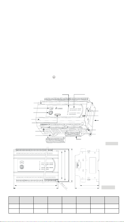
Product Profile & Dimension
POWER, RUN ERROR indicators, & COM
I/O terminal No.
Run/Stop switch
COM1 Communication
(RS-232C)port
I/O terminal No.
Model Name
COM2/COM3 (RS-485)
DIN rail clip
DVP40ES2
24DI / 16DO
I/O point indicators
I/O module
R
Remov able I/O term inal block
Output type
Mounting slot
(35mm)
I/O module clip
Direc t moun ting hole
[ Figure 1 ]
portconnection
90
98
106
110
Model
name
16ES2
00R/T
L1
L
24ES2
00R/T
32ES2
00R/T
Unit: mm
40ES2
00R/T
60ES2
00R/T
61.5
78
20EX2
00R/T
[ Figu re 2 ]
32ES2
11T
L 105 125 145 165 225 145 145
L1 97 117 137 157 217 137 137
- 1 -
Page 3
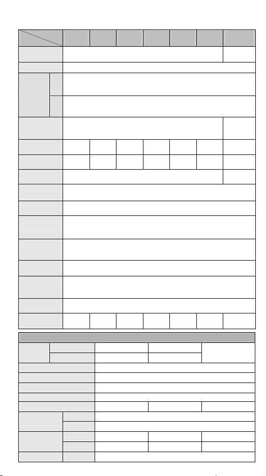
Electrical Specifications
Model
Item
Power supply
voltage
Connector European standard removable terminal block (Pin pitch: 5mm)
Operation
Power supply
fuse
Power
consumption
DC24V current
output
Power supply
protection
Volt age
withstand
Insulation
resistance
Noise immunity
Grounding
Environment
Agency
approvals
Vibration/shock
immunity
Weight
Input No.
type Digital input
Input type DC (SINK or SOURCE)
Input current 24VDC, 5mA
Input impedance 4.7KΩ
Max. frequency 100kHz 10kHz 60Hz
Action level
Response time
Filter time X0 ~ X7 Adjustable within 0 ~ 20ms in D1020 (Default: 10ms)
16ES2
24ES2
32ES2
40ES2
60ES2
00
00
00
00
100 ~ 240VAC (-15% ~ 10%)
DVP-ES2 starts to run when the power rises to 95 ~ 100VAC and stops
ES
when the power drops to 70VAC. If the power is suddenly cut off, the MPU
200
will continue running for 10ms.
DVP-ES2 starts to run when the power rises to 20.4VDC~28.8VDC and
ES
stops when the power drops to 17.5VDC. If the power is suddenly cut off,
211
the MPU will continue running for 10ms.
2A/250VAC
30VA 30VA 30VA 30VA 30VA 30VA 1. 8W
500mA 500mA 500mA 500mA 500mA 500mA
DC24V output short circuit protection
1,500VAC (Primary-secondary)
500VAC (Secondary-PE)
> 5MΩ at 500VDC (between all I/O points and ground)
ESD: 8KV Air Discharge
EFT: Power Line: 2KV, Digital I/O: 1KV, Analog & Communication I/O: 1KV
RS: 26MHz ~ 1GHz, 10V/m
The diameter of grounding wire shall not be less than that of L, N terminal of
the power supply. (When many PLCs are in use at the same time, please
make sure every PLC is properly grounded.)
Operation: 0°C~55°C (temperature), 50~95% (humidity), pollution degree 2
Storage: -25°C~70°C (temperature), 5~95% (humidity)
UL508
European community EMC Directive 89/336/EEC and Low Voltage Directive
73/23/EEC
International standards: IEC61131-2, IEC 68-2-6 (TEST Fc)/ IEC61131-2 &
IEC 68-2-27 (TEST Ea)
R: 377g
R: 414g
T: 387g
R: 489g
T: 432g
Input Point
T: 351g
ES200, EX200 X0, X2 X1, X3 ~ X7
ES211 X0 ~ X3 X4 ~ X7
Off → On >15VDC
On → Off < 5VDC
Off → On < 2.5μs < 20μs < 10ms
On → Off < 5μs < 50μs < 15ms
, 50/60Hz ±5%
, 1,500VAC (Primary-PE),
R: 554g
T: 498g
- 2 -
00
R: 696g
T: 614g
20EX2
R: 462g
T: 442g
32ES2
00
11T
24VDC
(-15~+20%)
2.5A /
30VDC,
Polyswitch
-
-
T: 321g
X10 ~ X17, X20 ~
#1
Page 4
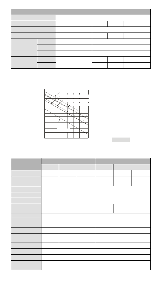
Output point type Relay-R Transistor-T
Output point number All Y0, Y2 Y1, Y3
Voltage specification < 250VAC, 30VDC
Y4~Y17, Y20~
5 ~ 30VDC
Max. frequency 1Hz 100kHz 10kHz 1kHz
Maximum load
Resistive 2A/1 point (5A/COM)
Inductive
#3
0.5A/1 point (4A/COM)
15W (30VDC)
#1
#2
#4
Lamp 20WDC/100WAC 2.5W(30VDC)
Output Point
Response time
Off → On < 2μs< 20μs < 100μs
On → Off
Approx .10ms
< 3μs< 30μs < 100μs
#1: Please refer to “I/O Terminal Layout” for the max. X/Y No. on each model.
#2: UP, ZP must work with external auxiliary power supply 24VDC (-15% ~ +20%), rated
consumption approx. 1mA/point.
#3: Life curves
0.1
0.2
120VAC Resistive
30VDC Inductive(t=7ms)
240VAC Inductive(cos 0.4)ψ=
120VAC Inductive(cos =0.4)ψ
30VDC
Inductive
( t=40m s)
0.3 0.7
0.5
12
Contact
Current(A)
[ Figure 3 ]
3,000
2,000
1,000
)
3
0
500
1
X
300
(
n
200
o
i
t
a
100
r
e
p
O
50
30
20
#4: ZP for NPN COM, UP for PNP COM.
A/D and D/A Specifications (For EX2 Model Only)
Items
Analog I/O range ±10V ±20mA 4 ~ 20mA#1±10V 0 ~ 20mA 4 ~ 20mA
Digital conversion
range
Resolution #2 12-bit
Input impedance > 1MΩ 250Ω -
Output impedance - 0.5Ω or lower
Tolerance carried
impedance
Overall accuracy
Response time 2ms (set up in D1118)
Absolute input
range
Digital data format
Average function Provided (set up in D1062)
Isolation method No Isolation between digital circuit and analog circuit
Protection
#1: V1.2 and above supports this mode. Please refer to the detailed explanation of D1115.
Analog Input (A/D) Analog Output (D/A)
Voltage Current Volt age Current
±2,000 ±2,000 0 ~ +2,000 ±2,000 0 ~ +4,000 0 ~ +4,000
- > 5KΩ < 500Ω
Non-linear accuracy: ±1% of full scale within the range of PLC operation
temperature
Maximum deviation: ±1% of full scale at 20mA and +10V
#3
2ms
#4
±15V ±32mA -
2’s complement of 16-bit, 12 significant bits
Voltage output has short circuit protection, but a long period of short
circuit may cause internal wire damage and open circuit of current output.
#5
-
- 3 -
#1
Page 5
#2: Resolution formula
Analog Input (A/D) Analog Output (D/A)
Voltage
20V
)
5mV( =
4000
#3: When the scan period is longer than 2ms or the set value, the setting will follow the scan
period.
#4: When the scan period is longer than 2ms, the setting will follow the scan period.
#5: When the sampling range is “1”, the present value will be read.
Current
μΑ(10 =
40mA
4000
Voltage
)
5mV( =
20V
4000
)
Current
μΑ(5 =
20mA
4000
)
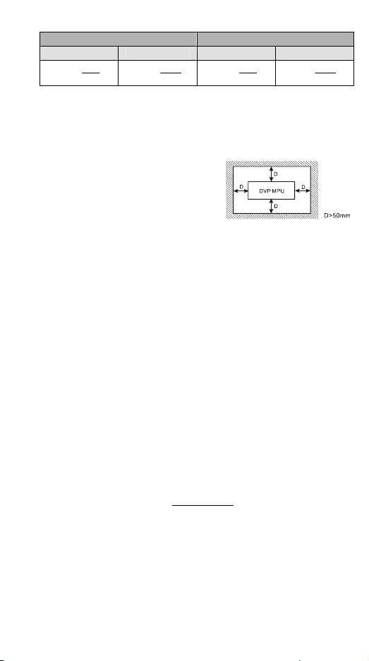
Installation
Please install the PLC in an enclosure with
sufficient space around it to allow heat dissipation,
as shown in the figure.
y Direct Mounting: Please use M4 screw
according to the dimension of the product.
y DIN Rail Mounting: When mounting the PLC to
35mm DIN rail, be sure to use the retaining clip to stop any side-to-side movement of
the PLC and reduce the chance of wires being loose. The retaining clip is at the
bottom of the PLC. To secure the PLC to DIN rail, pull down the clip, place it onto the
rail and gently push it up. To remove the PLC, pull the retaining clip down with a flat
screwdriver and gently remove the PLC from DIN rail.
Wiring
1. Use the 12-24 AWG single-core bare wire or the multi-core wire for the I/O wiring.
The PLC terminal screws should be tightened to 3.80 kg-cm (3.30 in-lbs) and
please use 60/75°C copper conductor only.
2. DO NOT wire empty terminal. DO NOT place the input signal wire and output
power wire in the same wiring circuit.
3. DO NOT drop tiny metallic conductor into the PLC while screwing and wiring.
y Please attach the dustproof sticker to the PLC before the installation to prevent
conductive objects from dropping in.
y Tear off the sticker before running the PLC to ensure normal heat dissipation.
Power Supply
The power input type for DVP-ES2 model is AC input. When operating DVP-ES2,
please note the following points:
1. The range of the input voltage should be 100 ~ 240VAC. The power supply should
be connected to L and N terminals. Please note that wiring AC110V or AC220V to
+24V output terminal or digital input points will result in serious damage on the PLC.
2. The AC power inputs for the MPU and the digital I/O module should be ON or OFF at
the same time.
3. Use 1.6mm wire (or longer) for the grounding of the PLC.
4. The power shutdown of less than 10ms will not affect the operation of the PLC.
However, power shutdown time that is too long or the drop of power supply voltage
will stop the running of the PLC, and all outputs will go “OFF”. When the power
returns to normal status, the PLC will automatically resume operation. (Care should
be taken on the latched auxiliary relays and registers inside the PLC when
programming.)
5. The +24V output is rated at 0.5A from MPU. DO NOT connect other external power
- 4 -
Page 6
supplies to this terminal. Every input terminal requires 5 ~ 7mA to be driven; e.g. the
16-point input will require approximately 100mA. Therefore, +24V terminal cannot
give output to the external load that is more than 400mA.
Safety Wiring
In PLC control system, many devices are controlled at the same time and actions of any
device could influence each other, i.e. breakdown of any device may cause the
breakdown of the entire auto-control system and danger. Therefore, we suggest you
wire a protection circuit at the power supply input terminal. See the figure below.
AC power supply:100 ~ 240VAC, 50/60Hz
○1
Emergency stop: This button cuts off the system power supply when accidental
○3
emergency takes place.
Power indicator
○4
Power supply circuit protection fuse (2A)
○6
DC power supply output: 24VDC, 500mA
○8
DC power supply: 24VDC
10
○
Digital I/O module (AC supply)
○12
DC power supply: 20.4VDC~28.8VDC
○14
Breaker
2
○
AC power supply load
5
○
DVP-PLC (main processing unit)
7
○
Grounding resistance: < 100Ω
9
○
Digital I/O module (DC supply)
11
○
Analog I/O module (DC supply)
13
○
I/O Point Wiring
There are 2 types of DC inputs, SINK and SOURCE. (See the example below. For
detailed point configuration, please refer to the specification of each model.)
y DC Signal IN – SINK mode
Input point loop equivalent circuit
+24V
24G
S/S
X0
X1
[ Fig ure 5 ]
y DC Signal IN – SOURCE mode
Input point loop equivalent circuit
+24V
24G
S/S
X0
X1
- 5 -
[ Figure 6 ]
Page 7
y Relay (R) output circuit wiring
[ Fig ure 7 ]
[ Figure 11 ]
1
DC power supply
○
Emergency stop: Uses external switch
○2
Fuse: Uses 5 ~ 10A fuse at the shared terminal of output contacts to protect the output
○3
circuit
Transient voltage suppressor: To extend the life span of contact.
○4
1. Diode suppression of DC load: Used when in smaller power (Figure 8)
2. Diode + Zener suppression of DC load: Used when in larger power and frequent On/Off
(Figure 9)
Incandescent light (resistive load)
○5
AC power supply
○6
Manually exclusive output: For example, Y4 and Y5 control the forward running and reverse
○7
running of the motor, forming an interlock for the external circuit, together with the PLC
internal program, to ensure safe protection in case of any unexpected errors.
Neon indicator
○8
Absorber: To reduce the interference on AC load (Figure 10)
○9
y Transistor (T) output circuit wiring
- 6 -
Page 8

A
A
1
DC power supply
○
Circuit protection fuse
○3
The output of the transistor model is “open collector”. If Y0/Y1 is set to pulse output, the
○4
output current has to be bigger than 0.1A to ensure normal operation of the model.
1. Diode suppression: Used when in smaller power (Figure 12)
2. Diode + Zener suppression: Used when in larger power and frequent On/Off (Figure 13)
Manually exclusive output: For example, Y3 and Y4 control the forward running and reverse
○5
running of the motor, forming an interlock for the external circuit, together with the PLC
internal program, to ensure safe protection in case of any unexpected errors.
2
Emergency stop
○
A/D and D/A External Wiring (For EX2 Model Only)
y A/D: Active y A/D: Passive
Volt age in put
+
U
IN
-
Shiel ded cabl e
Current input
+
U
IN
-
Ter mina l of
power module
y D/A
AC drive, recorder,
scale value...
AC drive, recorder,
scale value...
Note: When the A/D module is connected to current signals, make sure to short-circuit “V+”
Shiel ded cabl e
(100 or less)
Groundi ng
Voltage output
Isolation wire
Current output
Isolation wire
and “I+” terminals.
CH1
V0+
Ch3
V3+
24G
+24V
[ Fig ure 14 ]
CH1
CH2
[ Figure 16 ]
I0+
VI0-
FE
I3+
VI3-
FE
VO0
IO0
VO1
IO1
G
G
Volta ge input
+
U
IN
-
Current input
-
+
Terminal of
power module
Grounding
CH1
Shielde d cable
Ch3
Shielde d cable
(100 or less)
[ Figu re 15 ]
V0+
I0+
V0-
FE
V3+
I3+
VI3-
FE
24G
+24V
- 7 -
Page 9

RS-485 Wiring
1 2 2
D+ D- SG D+ D- SG SG D+ D-
3
3
4
Master node
○1
Terminal resistor
○3
Note: 1. Terminal resistors are suggested to be connected to master and the last slave with
resistor value of 120Ω.
2. To ensure communication quality, please apply double shielded twisted pair cable
(20AWG) for wiring.
3. When voltage drop occurs between the internal ground references of two
connect the systems with Signal Ground point (SG) for achieving equal potential
between systems so that a stable communication can be obtained.
4
2
Slave node
○
4
Shielded cable
○
Figure 17
systems,
I/O Terminal Layouts
y DVP16ES200R/T
DVP16ES2-R (8DI/8DO)
SG
DVP16ES2-T (8DI/8DO)
SG
D-D+
y DVP24ES200R/T
DVP24ES2-R (16DI/8DO)
SG
DVP24ES2-T (16DI/8DO)
SG
y DVP32ES200R/T
NC
DVP32ES2-R (16DI/16DO)
SG
DVP32ES2-T (16DI/16DO)
SG
y DVP40ES200R/T
DVP40ES2-R (24DI/16DO)
SG Y13
DVP40ES2-T (24DI/16DO)
SG Y12
S/S
24G+24V
NC
D-
D+D-D+
24G+24V
NC
ZPUP
D+
D-
NC
D-
D+D-D+
NC
D-
D+D-D+
24G+24V
D- Y7Y6Y5
D+D-D+
24G+24V
NC
D+D-D+
NC
D+D-D+
D- Y5Y4C1
NC
D- Y5Y4Y3
D+D-D+
X4X3X2X1X0S/S X7X6X5
24G+24V
X4X3X2X1X0S/S X7X6X5
24G+24V
Y0
UP
ZP
X2X1X0S/S
Y3Y2Y1Y0C0
X2X1X0S/S
X3 X15
X4X2X1X0S/S X7X6X5
24G+24V
X4X2X1X0S/S X7X6X5
X3
24G+24V
Y2Y1Y0C0
Y4C1
Y4Y3Y2Y1Y0ZP0UP0D- Y7Y6Y5
Y3Y2Y1Y0C0
Y2Y1Y0ZP0UP0
X4X3X2X1X0
Y4C1Y3Y2Y1Y0C0
X4X3X2X1X0S/S
Y4Y3Y2Y1Y0
Y3
Y2Y1
X5X4X3
X5X4X3
- 8 -
X7X6X5
Y7Y6Y5
X7X6X5
Y7Y6Y5
X15
X17X16X14X13X12X11X10
Y5
Y4C1
Y7Y6
X15
Y5
Y3
Y6
Y4
Y7
X13 X17
Y10C2
Y11C3Y13Y12
X13
ZP1UP1
Y10 Y13Y12Y11 Y15Y14 Y17Y16
Y7Y6 C2 Y12Y11Y10
X25
Y15
Y16
C3
Y14
Y17
X15
Y7Y6 UP1 Y11Y10ZP1
X25
Y13
Y15Y14 Y16 Y17
X17X16X14X13X12X11X10
X15X14X12X11X10X7X6
X16
Y15Y14
X15X14X12X11X10X7X6
X16
X17
X20
X17X1 6X14X13X12X11X10
X27X26X24X23X22X21
X17X16X14X1 3X12X11X10
X20
X27X26X24X23X22X21
Y17Y16
Page 10

y DVP60ES200R/T
X3 X15
DVP60ES2-R (36DI/24DO)
DVP60ES2-T (36DI/24DO)
D- Y5Y4C1D+D-D+
SG Y13
Y15
Y14
C3
D- Y5Y4Y3D+D-D+
SG Y12
Y13
Y15
Y16
Y14
X4X2X1X0S/ S X7X6X5NC X17X16X14X13X12X11X10
24G+24V
X25 X31 X32 X33 X37 X43
Y16 Y20C4
Y17
24G+24V
X25 X31 X32 X33 X37 X43
UP2
Y17 Y21
Y3Y2Y1Y0C0
X27X26X24X23X22X21
X30
Y22Y21 C5Y23
X4X2X1X0S/S X7X6X5NC X17X16X14X13X1 2X11X10
X3 X15
Y2Y1Y0ZP0UP0
X27X2 6X24X23X22X21
X30
Y20 Y23
ZP2
X35X34 X36
Y25Y24
X35X34 X3 6
Y25
Y22
Y24
y DVP20EX200R/T
DVP20EX2-R (8DI/6DO /4AI/2AO)
NC
D- Y5Y4C1
D+D-D+
NC
DVP20EX2-T (8DI/6 DO/4AI/2AO)
D- Y5Y4Y3
D+D-D+
X4X3X2X1X0S/S X7X6X5
24G+24V
24G+24V
Y3Y2Y1Y0C0
X4X3X2X1X0S/S X7X6X5
Y2Y1Y0ZPUP
y DVP32ES211T
SG3 D-D+ SG2 D-D+
DVP32ES211T (16DI/16DO)
NC
X2X1X0S/S X5X4X3
Y4Y3Y2Y1Y0ZP0UP0 Y7Y6Y5NC0V24V
Y7Y6 C2 Y12Y11Y10
X41X40 X42
Y27Y26
Y7Y6 UP1 Y11Y10ZP1
X41X4 0 X42
Y26
Y27
X13 X17
X15X14X12X11X10X7X6
X16
ZP1UP1
Y10 Y13Y12Y11 Y15Y14 Y17Y16
X20
X20
I2+V2+VI1-I1+V1 +VI0- VI2-I0+V0+FE
AGIO 0VO0VI3-I3+V3+ VO1FE IO1 AGSG
I2+V2+VI1-I1+V1+VI0- VI 2-I0+V0+FE
AGIO0VO0VI3-I3+V3+ VO1FE IO1 AGSG
- 9 -
Page 11

………………………………………………………………… 繁體中文 ………………………………………………………………………
感謝您採用台達 DVP-ES2 系列可程式控制器。此系列提供 16 ~ 60 點數的主機及 8 ~ 32
點數位輸入/輸出模組,含主機最大輸入∕輸出擴充最多可達 256 點。另依主機輸入∕輸
出點數、電源、數位輸入∕輸出與類比輸入∕輸出模組搭配使用,可滿足各種應用場合。
a 本安裝說明書提供給使用者電氣規格、功能規格、安裝配線之相關注意事項。其他詳
細之程式設計及指令說明請見 DVP-ES2 操作手冊【程式篇】,選購之周邊裝置詳細說
明請見該產品隨機安裝說明書。
a 本機為開放型 (OPEN TYPE) 機殼,因此使用者使用本機時,必須將之安裝於具防
塵、防潮及免於電擊∕衝擊意外之外殼配線箱內。另必須具備保護措施(如:特殊之
工具或鑰匙才可打開)防止非維護人員操作或意外衝擊本體,造成危險及損壞。
a 交流輸入電源不可連接於輸入∕出信號端,否則可能造成嚴重損壞,請在上電之前再
次確認電源配線。請勿在上電時觸摸任何端子。本體上之接地端子 務必正確的接
地,可提高產品抗雜訊能力。
產品外觀尺寸與部位介紹
電源、運行 錯誤 指示燈、及
輸出/入端子 編號
Run/Stop
開關
COM1
程式通訊埠
()RS-232C
輸出/入端子 編號
機種型號
COM2/COM3 (RS-485)
DIN 軌固定扣
y 詳細尺寸圖請參閱英文版頁碼 1 之[Figure 2],單位:mm。
機種
16ES2
型號
00R/T
L 105 125 145 165 225 145 145
L1 97 117 137 157 217 137 137
24ES2
00R/T
COM
DVP40ES2
24DI / 16D O
32ES2
00R/T
40ES2
00R/T
輸出 點指示燈/入
R
脫落式輸出/ 入端子
60ES2
00R/T
I/O
輸出類型
DIN (35mm)
軌槽
模組固定扣
I/O
直接固定孔
20EX2
00R/T
模組連接埠
32ES2
11T
電氣規格
機種
項目
電源電壓 100 ~ 240VAC (-15% ~ 10%),50 / 60Hz ± 5%
連接方式 脫落式歐式端子座 (端點距離:5mm)
動作
規格
電源保險絲容量 2A / 250VAC
消耗功率 30VA 30VA 30VA 30VA 30VA 30VA 1.8W
DC24V 電流輸出 500mA 500mA 500mA 500mA 500m A 500mA -
16ES2
24ES2
32ES2
40ES2
00
00
00
當電源緩升至 95 ~ 100VAC 時,PLC 開始動作,當電源緩降至 70VAC 時,
ES200
PLC 停止動作。電源瞬間斷電 10ms 以內繼續運行。
當電源緩升至 20.4VDC~28.8VDC 時,PLC 開始動作,當電源緩降至
ES211
17.5VDC 時,PLC 停止動作。電源瞬間斷電 10ms 以內繼續運行。
00
60ES2
00
- 10 -
20EX2
00
32ES2
11T
24VDC
(-15~+20%)
2.5A /
30VDC
可恢復式
Page 12

機種
項目
電源保護 DC24V 輸出具短路保護 -
突波電壓耐受量
絕緣阻抗 5MΩ 以上(所有輸出/入點對地之間 500VDC)
雜訊免疫力
接地
操作∕儲存環境
認證標準
耐振動∕衝擊
重量
輸入點
No.
輸入點類型 數位輸入
輸入形式 直流(SINK 或 SOURCE)
輸入電流 24VDC, 5mA
輸入阻抗 4.7KΩ
最高切換頻率
動作位準
反應時間
濾波時間 X0 ~ X7 由 D1020 可作 0 ~ 20ms 的調整(預設值 10ms)
輸出點形式 繼電器-R 電晶體-T
輸出點 No. 全部 Y0, Y2 Y1, Y3 Y4~Y17, Y20 ~
電壓規格 250VAC, 30VDC 以下 5 ~ 30VDC #2
最高切換頻率 1Hz
最大負載
反應時間
#1:主機上最大點數編號請參考「輸入∕輸出端子台配置」。
#2:UP, ZP 必須外加輔助電源 24VDC (-15% ~ +20%) 額定消耗約 1mA/點。
#3:生命週期曲線圖請參閱英文版頁碼 3 之[Figure 3]。
16ES2
24ES2
32ES2
40ES2
60ES2
00
00
00
00
1,500VAC (Primary-secondary)、1,500VAC (Primary-PE)、500VAC
(Secondary-PE)
ESD: 8KV Air Discharge
EFT: Power Line: 2KV,Dig ital I/O: 1KV, Analog & Communication I/O: 1KV
RS: 26MHz ~ 1GHz,10V/m
接地配線之線徑不得小於電源端 L, N 之線徑(多台 PLC 同時使用時,請務
必單點接地)
操作:0°C ~ 55°C(溫度),50 ~ 95%(濕度)污染等級 2
儲存:-25°C ~ 70°C (溫度),5 ~ 95%(濕度)
UL508
European community EMC Directive 89/336/EEC and Low Voltage
Directive 73/23/EEC
國際標準規範 IEC61131-2,IEC 68-2-6 (TEST Fc)/IEC61131-2 & IEC
68-2-27 (TEST Ea)
R: 377g
R: 414g
R: 489g
T: 351g
T: 387g
輸 入 點 電 氣 規 格
ES200, EX200 X0, X2 X1, X3 ~ X7
ES211
Off → On > 15VDC
On → Off < 5VDC
Off → On
On → Off
電阻性 2A/1 點(5A/COM)
電感性
燈泡 20WDC/100WAC
Off → On < 2μs< 20μs < 100μs
On → Off
X0 ~ X3 X4 ~ X7
100kHz 10kHz 60Hz
< 2.5μs < 20μs < 10ms
< 5μs < 50μs < 15ms
輸 出 點 電 氣 規 格
#3
約 10 ms
T: 432g
R: 554g
T: 498g
100kHz 10kHz 1kHz
< 3μs< 30μs < 100μs
- 11 -
20EX2
00
00
R: 696g
R: 462g
T: 614g
T: 442g
X10 ~ X17, X20 ~
0.5A/1 點 (4A/COM)
15W (30VDC)
2.5W(30VDC)
32ES2
T: 321g
#4
11T
#1
#1
Page 13

#4:NPN 模式使用 ZP 端點,PNP 模式使用 UP 端點。
AD/DA 規格(EX2 機種適用)
項 目
類比輸入∕輸出範圍
數位轉換範圍
解析度 #2 12-bit
輸入阻抗 > 1MΩ 250 Ω -
輸出阻抗 - 0.5Ω or lower
容許負載阻抗 - > 5KΩ < 500Ω
總和精密度
回應時間 2ms (可由 D1118 設定)
絕對輸入範圍 ±15V ±32mA -
數位資料格式 16 位 2 補數(有效位 12 bits)
平均功能 是 (由 D1062 設定)
隔離方式 數位及類比電路間未隔離
保護
#1:在 V1.2 版(含)以上支援此模式,詳細請參考 D1115 說明。
#2:解析度計算
類比電壓輸入 類比電流輸入 類比電壓輸出 類比電流輸出
20V
5mV( =
4000
#3:當掃描週期大於 2ms 或設定值時,以掃描週期為主。
#4:當掃描週期大於 2ms 時,以掃描週期為主。
#5:當平均次數 D1062 為 1 時,即是讀取現在值。
類比輸入 (A/D) 類比輸出 (D/A)
電壓輸入 電流輸入 電壓輸出 電流輸出
±10V ±20mA 4 ~ 20mA
±2,000 ±2,000 0 ~ +2,000 ±2,000 0 ~ +4,000 0 ~ +4,000
非線性精度:±1%在整個溫度範圍內滿刻度時
最大誤差:±1%在滿刻度 20mA 及+10V 時
電壓輸出有短路保護但須注意長時間短路仍有可能造成內部線路損壞,
電流輸出可開路。
μΑ(10 =
40mA
4000
)
#1
±10V 0 ~ 20mA 4 ~ 20mA
#3
2ms
#5
-
)
5mV( =
20V
4000
)
#4
μΑ(5 =
20mA
4000
#1
)
安裝方式
PLC 在安裝時,請裝配於封閉式之控制箱內,其
周圍應保持一定之空間(如圖所示),以確保 PLC
散熱功能正常。
y 直接鎖螺絲方式:請依產品外形尺寸並使用
M4 螺絲。
y DIN 鋁軌之安裝方法:適用於 35mm 之 DIN 鋁軌。在將主機掛上鋁軌時,請先將主機
(或數位輸入/輸出模組)下方之固定塑膠片,以一字形起子插入凹槽並向外撐開拉出,
再將主機(或數位輸入/輸出模組)掛上鋁軌,之後將固定塑膠片壓扣回去即可。欲取
下主機時,同樣以一字形起子先將固定塑膠片撐開,再將主機以往外向上的方式取出即
可。該固定機構塑膠片為保持型,因此撐開後便不會彈回去。
配線端子
1. 輸出∕輸入配線端請使用 12-24 AWG 單蕊祼線或多蕊線。PLC 端子鏍絲扭力為3.80
kg-cm (3.30 Ib-in)。請使用 60/75°C 銅導線。
2. 空端子 • 請勿配線。輸入點信號線與輸出點等動力線請勿置於同一線槽內。
3. 鎖螺絲及配線時請避免微小的金屬導體掉入 PLC 內部。
y 安裝前請貼上防塵貼紙,防止導電異物掉入。
- 12 -
Page 14

y 運轉前請撕下防塵貼紙,保持良好散熱效果。
電源端
DVP-ES2 之電源輸入為交流輸入機種時,在使用上應注意下列事項:
1. 交流電源輸入電壓,範圍寬廣 (100 ~ 240VAC),電源請接於 L、N 兩端,如果將AC110V
或 AC220V 接至+24V 輸出端或數位輸入點端,將使PLC 損壞,請使用者特別注意。
2. 主機及數位輸入/輸出模組之交流電源輸入請同時作 On 或 Off 的動作。
3. 主機之接地端使用 1.6mm 以上之電線接地。
4. 當停電時間低於 10ms 時,PLC 不受影響繼續運轉,當停電時間過長或電源電壓下降
將使 PLC 停止運轉,輸出全部 Off,當電源恢復正常時,PLC 亦自動回復運轉。(PLC
內部具有停電保持的輔助繼電器及暫存器,使用者在程式設計規劃時應注意使用。)
5. +24V 電源供應輸出端,最大為 0.5A,請勿將其他的外部電源連接至此端子。每個輸
入點驅動電流必須 5 ~ 7mA,若以 16 點輸入計算,大約需 100mA,因此+24 V 輸出給
外部負載不可大於 400mA。
安全配線回路
由於 PLC 控制許多裝置,任一裝置的動作可能都會影響其他裝置的動作,因此任一裝置
的故障都可能會造成整個自動控制系統失控,甚至造成危險。所以在電源端輸入回路,建
議的保護回路配置圖如英文版頁碼 5 之[Figure 4]所示:
○1 交流電源供應:100 ~ 240VAC, 50/60Hz ○
2
斷路器
○3 緊急停止:為預防突發狀況發生,設置緊急停止按鈕,可在狀況發生時,切斷系統電源。
○4 電源指示燈 ○
○6 電源回路保護用保險絲(2A) ○
○8 直流電源供應輸出:24VDC,500mA ○
10
○
直流電源供應:24VDC ○
○12 數位輸入/輸出模組(交流供應) ○
5
交流電源負載
7
DVP PLC 主機本體
9
接地阻抗 100Ω 以下
11
數位輸入/輸出模組(直流供應)
13
類比輸入/輸出模組(直流供應)
○14 直流電源供應:20.4VDC ~ 28.8VDC
輸入∕輸出點之配線
輸入點之入力信號為直流電源 DC 輸入,DC 型式共有兩種接法:SINK 及 SOURCE,其
定義如下:(以下為舉例說明,詳細點數配置請見各機種)
y 直流形式(DC Signal IN)配線 – SINK 模式
輸入點回路等效電路配線圖,請參閱英文版頁碼 6 之[Figure 5]。
y 直流形式(DC Signal IN)配線 – SOURCE 模式
輸入點回路等效電路配線圖,請參閱英文版頁碼 6 之[Figure 6]。
y 實用之繼電器輸出回路配線
詳細配線圖請參閱英文版頁碼 6 之[Figure 7]。
1
○
直流電源供給 ○2緊急停止:使用外部開關
○3 保險絲:使用 5 ~ 10A 的保險絲容量於輸出接點的共用點,保護輸出點回路。
○4 突波吸收二極體:可增加接點壽命。
1. DC 負載電源之二極體抑制:功率較小時使用(請參閱英文版頁碼 6 之[Figure 8])
2. DC 負載電源之二極體+Zener 抑制:大功率且On/Off 頻繁時使用 (請參閱英文版頁碼
6 之[Figure 9])
○5 白熾燈(電阻性負載) ○
○7
互斥輸出:例如,將 Y4 與 Y5 用以控制對應馬達的正轉及反轉,使外部電路形成互鎖,配
合 PLC 內部程式,確保任何異常突發狀況發生時,均有安全的保護措施。
○8 指示燈:氖燈
○9 突波吸收器:可減少交流負載上的雜訊(請參閱英文版頁碼 6 之[Figure 10])
- 13 -
6
交流電源供給
Page 15

y 實用之電晶體輸出回路配線
A
A
隔離線
電壓輸出
詳細配線圖請參閱英文版頁碼 6 之[Figure 11]。
1
○
直流電源供應 ○2緊急停止 ○3電路回路保護用保險絲
○4
因電晶體模組輸出均為開集極輸出 (Open Collector),若 Y0/Y1 設定為脈波串輸出,為確
保電晶體模組能夠動作正常,其輸出提升電阻,必須維持輸出電流大於 0.1A。
1. 二極體抑制:功率較小時使用(請參閱英文版頁碼 7 之[Figure 12])
2. 二極體+Zener 抑制:大功率且 On/Off 頻繁時使用(請參閱英文版頁碼 7 之[Figure 13])
○5 互斥輸出:例如,將 Y3 與 Y4 用以控制對應馬達的正轉及反轉,使外部電路形成互鎖,配
合 PLC 內部程式,確保任何異常突發狀況發生時,均有安全的保護措施。
A/D ᄃ D/A γొቢĞEX2 ፟ዋϡğ
y A/D:主動式 y A/D:被動式
U
IN
U
IN
接至電源模
組之 端
電壓輸入
+
-
電流輸入
+
-
第三種接地
隔離線
隔離線
( 100 )接地阻抗 以下
CH1
Ch3
V0+
I0+
VI0-
FE
V3+
I3+
VI3-
FE
24G
+24V
y D/A
CH1
VO0
IO0
CH2
VO1
IO1
G
G
變頻器、記錄器
比例閥 ...
變頻器、記錄器
比例閥 ...
電流輸出
隔離線
註:如果連接電流訊號時,V+ 及 I+ 端子請務必短路。
+
U
IN
-
接至電源模
組之 端
電壓輸入
電流輸入
-
+
第三種接地
CH1
隔離線
Ch3
隔離線
( 100 )接地阻抗 以下
RS-485 ޙᛉତቢ
詳細接線圖請參閱英文版頁碼 7 之[Figure 16]。
○1
主站
2
○
從站
附註:1. 終端電阻建議連接於主站及最後一台從站上,且其電阻值建議為 120Ω。
2. 為確保連線品質,線材建議使用具有雙層遮蔽線之通訊雙絞線(20AWG)。
3. 當兩個系統內部地準位存在壓降,可透過連接 SG (Signal Ground) 讓地準位等電位,
使通訊更加穩定。
3
○
終端電阻
○4
遮蔽線
V0+
I0+
V0-
FE
V3+
I3+
VI3-
FE
24G
+24V
輸入∕輸出端子台配置
請參閱英文版頁碼 7~8 之端子配置,在此語言版本省略說明。
- 14 -
Page 16

…………………………………………………………………… 简体中文 …………………………………………………………………
感谢您采用台达 DVP-ES2 系列可编程控制器。此系列提供 16 ~ 60 点数的主机及 8 ~ 32
点数字量输入/输出模块,含主机最大输入/输出扩展最多可达 256 点。另依主机输入/
输出点数、电源、数字量输入/输出与模拟量输入/输出模块搭配使用,可满足各种应用
场合。
a 本安装说明书提供给使用者电气规格、功能规格、安装配线的相关注意事项。其它详
细的程序设计及指令说明请见 DVP-ES2 操作手册【程序篇】,选购的周边装置详细说
明请见该产品随机安装说明书。
a 本机为开放型 (OPEN TYPE) 机种,因此使用者使用本机时,必须将其安装于具防尘、
防潮及免于电击/冲击意外的外壳配线箱内。另必须具备保护措施(如:特殊的工具
或钥匙才可打开)防止非维护人员操作或意外冲击本体,造成危险及损坏。
a 交流输入电源不可连接于输入/出信号端,否则可能造成严重损坏,请在上电之前再
次确认电源配线。请勿在上电时触摸任何端子。本体上的接地端子 务必正确的接
地,可提高产品抗干扰能力。
產品外觀尺寸與部位介紹
电源、运行 错误 指示灯、及 COM
输出 入端子编号/
Run/Stop 开关
COM1
程序通讯口
RS-232C()
输出 入端子编 号/
机种型号
COM 2/COM3 (RS -485)
DIN 轨固定扣
DVP40ES2
24DI / 16D O
y 详细尺寸图请参阅英文版页码 1 之[Figure 2],单位:mm。
机种
型号
16ES2
00R/T
24ES2
00R/T
32ES2
00R/T
40ES2
00R/T
L 105 125 145 165 225 145 145
L1 97 117 137 157 217 137 137
输出 点指示 灯/入
R
脱落式输出 入 端子/
60ES2
00R/T
DIN (35mm) 轨槽
直接固定孔
20EX2
00R/T
模块连接端口I/O
输出类型
模块固定扣I/O
32ES2
11T
電氣規格
机种
项目
电源电压 100 ~ 240VAC (-15% ~ 10%),50/60Hz ± 5%
连接方式 脱落式欧式端子座 (端点距离:5m m)
动作
规格
电源保险丝容量 2A/250VAC
消耗功率 30VA 30VA 30VA 30VA 30VA 30VA 1.8W
16ES2
24ES2
32ES2
40ES2
00
00
00
当电源缓升至 95 ~ 100VAC 时,PLC 开始动作,当电源缓降至 70VAC 时,
ES200
PLC 停止动作。电源瞬间断电 10ms 以内继续运行。
当电源缓升至 20.4VDC~28.8VDC 时,PLC 开始动作,当电源缓降至
ES211
17.5VDC 时,PLC 停止动作。电源瞬间断电 10ms 以内继续运行。
00
60ES
200
- 15 -
20EX2
00
32ES2
11T
24VDC
(-15~+20%)
2.5A /
30VDC
可恢复式
Page 17

机种
项目
DC24V 电流输出 500mA 500mA 500mA 500mA 500mA 500mA -
电源保护 DC24V 输出具短路保护 -
突波电压承受量
绝缘阻抗 5MΩ 以上(所有输出/入点对地之间 500VDC)
干扰免疫力
接地
操作∕储存环境
认证标准
耐振动∕冲击
重量
输入点
No.
输入点类型 数字量输入
输入形式 直流(漏型或源型)
输入电流 24VDC, 5mA
输入阻抗 4.7KΩ
最高切换频率
动作临界点
反应时间
滤波时间 X0 ~ X7 由 D1020 可作 0 ~ 20ms 的调整 (默认值 10ms)
输出点形式 继电器-R 晶体管-T
输出点 No. 全部 Y0, Y2 Y1, Y3 Y4~Y17, Y20 ~
电压规格 250VAC, 30VDC 以下 5~30VDC #2
最高切换频率 1Hz
最大负载
反应时间
#1:主机上最大点数编号请参考「输入╱输出端子台配置」。
#2:UP, ZP 必须外加辅助电源 24VDC (-15% ~ +20%) 额定消耗约 1mA/点。
#3:生命周期曲线图请参阅英文版页码 3 之[Figure 3]。
16ES2
24ES2
32ES2
40ES2
60ES
00
00
00
00
1,500VAC (Primary-secondary)、1,500VAC (Primary-PE)、500VAC
(Secondary-PE)
ESD: 8KV Air Discharge
EFT: Power Line: 2KV, Digital I/O: 1KV, Analog & Communication I/O: 1KV
RS: 26MHz ~ 1GHz, 10V/m
接地配线的线径不得小于电源端 L, N 的线径(多台 PLC 同时使用时,请务
必单点接地)
操作:0°C ~ 55°C(温度),50 ~ 95%(湿度)污染等级 2
储存:-25°C ~ 70°C (温度),5 ~ 95%(湿度)
UL508
European community EMC Directive 89/336/EEC and Low Voltage
Directive 73/23/EEC
国际标准规范 IEC61131-2, IEC 68-2-6 (TEST Fc)/IEC61131-2 & IEC
68-2-27 (TEST Ea)
R: 377g
R: 414g
R: 489g
T: 351g
T: 387g
ES200, EX200
ES211
Off → On > 15VDC
On → Off < 5VDC
Off → On
On → Off
电阻性 2A/1 点(5A/COM) 0.5A/1 点(4A/COM)#4
电感性
灯泡 20WDC/100WAC
Off → On
On → Off
输 入 点 电 气 规 格
X0, X2 X1, X3 ~ X7
X0 ~ X3 X4 ~ X7
100kHz 10kHz 60Hz
< 2.5μs < 20μs < 10ms
< 5μs < 50μs < 15ms
输 出 点 电 气 规 格
约 10 ms
T: 432g
#3
R: 554g
T: 498g
100kHz 10kHz 1kHz
< 2μs< 20μs < 100μs
< 3μs< 30μs < 100μs
- 16 -
200
R: 696g
T: 614g
15W (30VDC)
2.5W(30VDC)
20EX2
00
R: 462g
T: 442g
X10 ~ X17, X20 ~
32ES2
11T
T: 321g
#1
#1
Page 18

#4:NPN 模式使用 ZP 端点,PNP 模式使用 UP 端点。
A/D 与 D/A 规格(EX2 机种适用)
项 目
模拟量输入/输出
范围
数字转换范围 ±2,000 ±2,000 0 ~ +2,000 ±2,000 0 ~ +4,000 0 ~ +4,000
分辨率 #2 12-bit
输入阻抗 > 1MΩ 250 Ω -
输出阻抗 - 0.5Ω or lower
允许负载阻抗 - > 5KΩ < 500Ω
总和
精密度
响应时间 2ms (可由 D1118 设定)
绝对输入范围 ±15 V ±32m A -
数字数据格式 16 位 2 补码(有效位 12 bits)
平均功能 是 (由 D1062 设定)
隔离方式 数字及模拟电路间未隔离
保护
#1:在 V1.2 版(含)以上支持此模式,详细请参考 D111 5 说明。
#2:分辨率计算
模拟量输电压输入 模拟量输电流输入 模拟量输电压输出 模拟量输电流输出
20V
5mV( =
4000
#3:当扫描周期大于 2ms 或设定值时, 以扫描周期为主。
#4:当扫描周期大于 2ms 时,以扫描周期为主。
#5:当平均次数 D1062 为 1 时,即读取现在值。
模拟量输入 (A/D) 模拟量输出 (D/A)
电压输入 电流输入 电压输出 电流输出
±10V ±20mA 4 ~ 20mA
非线性精度:±1%在整个温度范围内满刻度时
最大误差:±1%在满刻度 20mA 及+10V 时
电压输出有短路保护但须注意长时间短路仍有可能造成内部线路损坏,
电流输出可开路。
)
40mA
μΑ(10 = )
4000
#1
±10V 0 ~ 20mA 4 ~ 20mA
#3
2ms
#5
-
5mV( =
20V
4000
)
#4
μΑ(5 =
20mA
4000
#1
)
安裝方式
PLC 在安装时,请装配于封闭式的控制箱内,其
周围应保持一定的空间(如图所示),以确保 PLC
散热功能正常。
y 直接锁螺丝方式:请依产品外形尺寸并使用
M4 螺丝。
y DIN 铝轨的安装方法:适用于 35mm 的 DIN 铝轨。在将主机挂上铝轨时,请先将主机
(或数字量输入/输出模块)下方的固定塑料片,以一字形起子插入凹槽并向外撑开拉
出,再将主机(或数字量输入/输出模块)挂上铝轨,之后将固定塑料片压扣回去即可。
欲取下主机时,同样以一字形起子先将固定塑料片撑开,再将主机以往外向上的方式
取出即可。该固定机构塑料片为保持型,因此撑开后便不会弹回去。
配線端子
1. 输出/入配线端请使用 12-24AWG 单蕊祼线或多蕊线,端子规格如图所示。PLC 端
子镙丝扭力为 3.80 kg-cm (3.30 Ib-in)。请使用 60/75°C 铜导线
2. 空端子 • 请勿配线。输入点信号线与输出点等动力线请勿置于同一线槽内。
3. 锁螺丝及配线时请避免微小的金属导体掉入 PLC 内部。
y 安装前请贴上防尘贴纸,防止导电异物掉入。
y 运转前请撕下防尘贴纸,保持良好散热效果。
- 17 -
Page 19

電源端
DVP-ES2 的电源输入为交流输入机种时,在使用上应注意下列事项:
1. 交流电源输入电压,范围大小(100 ~ 240VAC),电源请接于 L、N 两端,如果将 AC110V
或 AC220V 接至+24V 输出端或数字量输入点端,将使 PLC 损坏,请使用者特别注意。
2. 主机及数字量输入/输出模块的交流电源输入请同时作 On 或 Off 的动作。
3. 主机的接地端使用 1.6mm 以上的电线接地。
4. 当停电时间低于 10ms 时,PLC 不受影响继续运转,当停电时间过长或电源电压下降
将使 PLC 停止运转,输出全部 Off,当电源恢复正常时,PLC 亦自动恢复运转。(PLC
内部具有停电保持的辅助继电器及寄存器,使用者在程序设计规划时别注意使用。)
5. +24V 电源供应输出端,最大为 0.5A,请勿将其它的外部电源连接至此端子。每个输
入点驱动电流必须 5 ~ 7mA,若以 16 点输入计算,大约需 100mA,因 此 +24V 输出给
外部负载不可大于 400mA。
安全配線回路
由于 PLC 控制许多装置,任一装置的动作可能都会影响其它装置的动作,因此任一装置
的故障都可能会造成整个自动控制系统失控,甚至造成危险。所以在电源端输入回路,建
议的保护回路配置图如英文版页码 5 之[Figure 4]所示:
○1
交流供应电源:100 ~ 240VAC, 50/60Hz
○3
紧急停止:为预防突发状况发生,设置紧急停止按钮,可在状况发生时,切断系统电源。
○4
电源指示灯
○6
电源回路保护用保险丝(2A)
○8
直流供应电源输出:24VDC,500mA
10
○
直流供应电源:24VDC
○12
数字量输入/输出模块(交流供应)
○14
直流电源供应:20.4VDC ~ 28.8VDC
2
○
断路器
5
○
交流电源负载
7
○
DVP PLC 主机本体
9
○
接地阻抗 100Ω 以下
11
○
数字量输入/输出模块(直流供应)
13
○
模拟量输入/输出模块(直流供应)
輸入∕輸出點之配線
输入点的接入信号为直流电源 DC 输入,DC 型式共有两种接法:漏型及源型,其定义如
下:(以下为举例说明,详细点数配置请见各机种)
y 直流形式(DC Signal IN)配线 – 漏型模式
输入点回路等效电路配线图,请参阅英文版页码 6 之[Figure 5]。
y 直流形式(DC Signal IN)配线 – 源型模式
输入点回路等效电路配线图,请参阅英文版页码 6 之[Figure 6]。
y 实用的继电器输出回路配线
详细配线图请参阅英文版页码 6 之[Figure 7]。
1
○
直流电源供给 ○2紧急停止:使用外部开关
○3 保险丝:于输出接点的公共端使用容量 5 ~ 10A 的保险丝,保护输出点回路。
○4 突波吸收二极管:可增加接点寿命。
1. DC 负载电源的二极管抑制:功率较小时使用(请参阅英文版页码 6 之[Figure 8])
2. DC 负载电源的二极管+Zener 抑制:大功率及 On/Off 频繁时使用(请参阅英文版页码 6
之[Figure 9])
○5 白炽灯(电阻性负载) ○
○7 互斥输出:例如,将 Y4 与 Y5 用于控制对应马达的正转及反转,使外部电路形成互锁,配
合 PLC 内部程序,确保任何异常突发状况发生时,均有安全的保护措施。
○8 指示灯:氖灯
○9 突波吸收器:可减少交流负载上的干扰(请参阅英文版页码 6 之[Figure 10])
- 18 -
6
交流电源供给
Page 20

y 实用的晶体管输出回路配线
A
A
详细配线图请参阅英文版页码 6 之[Figure 11]。
1
○
直流供应电源 ○
○4 因晶体管模块输出均为开集极输出 (Open Collector),若 Y0/Y1 设定为脉冲式输出,为确
保晶体管模块能够动作正常,其输出提升电阻,必须维持输出电流大于 0.1A。
1. 二极管抑制:功率较小时使用(请参阅英文版页码 7 之[Figure 12])
2. 二极管+Zener 抑制:大功率及 On/Off 频繁时使用(请参阅英文版页码 7 之[Figure 13])
○5 互斥输出:例如,将 Y3 与 Y4 用于控制对应马达的正转及反转,使外部电路形成互锁,配
合 PLC 内部程序,确保任何异常突发状况发生时,均有安全的保护措施。
2
紧急停止 ○
3
电路回路保护用保险丝
A/D 與 D/A 外部配線(EX2 机种适用)
y A/D:主动式 y A/D:被动式
U
IN
U
IN
接至电源模
组之 端
电压输入
+
-
电输入流
+
-
( ) 接地阻抗 以下
接地
隔离线
隔离线
CH1
V0+
I0+
VI0-
FE
Ch3
V3+
I3+
VI3-
FE
24G
+24V
100
y D/A
变频器、记录器
比例阀...
变频器、记录器
比例阀...
电压输出
隔离线
电流输出
隔离线
CH1
CH2
VO0
IO0
VO1
IO1
G
G
注:如果连接电流信号时,V+ 及 I+ 端子请务必短路。
+
U
IN
-
电压输入
电输入流
-
+
接至电源模
组之 端
接地
隔离线
隔离线
( ) 接地阻抗 以下
100
CH1
Ch3
RS-485 建議接線
详细接线图请参阅英文版页码 7 的[Figure 16]。
○1 主站 ○
2
从站 ○3终端电阻 ○
附注:1. 终端电阻建议连接于主站及最后一台从站上,且其阻值建议为 120Ω。
2. 为确保联机质量,线材建议使用具有双层屏蔽线的通讯双绞线(20AWG)。
3. 当两个系统内部地准位存在压降,可透过连接 SG (Signal Gr ound) 让地准位等电位,
使通讯更加稳定。
4
屏蔽线
V0+
I0+
V0-
FE
V3+
I3+
VI3-
FE
24G
+24V
輸入∕輸出端子排配置
请参阅英文版页码 7~8 之端子配置,在此语言版本省略说明。
- 19 -
Page 21

DVP-1130070-02
Model
Voltaj çıkışında kısa devre koruması vardır, fakat uzun sureli kısa devre durumunda dahili devreler
Madde
Titreşim/şok
bağışıklığı
Ağırlık
Giriş No.
Tip Dijital giriş
Giriş tipi DC (SINK veya SOURCE)
Giriş akımı 24VDC, 5mA
Giriş empedansı 4.7KΩ
Maksimum frekans 100kHz 10kHz 60Hz
Aktif
seviye
Cevap
zamanı
Filtre
zamanı
Çıkış tipi Röle-R Transistor-T
Çıkış numarası Tümü Y0, Y2 Y1, Y3 Y4~Y17, Y20~#1
Voltaj özellikleri < 250VAC, 30VDC 5 ~ 30VDC #2
Maksimum frekans 1Hz 100kHz 10kHz 1kHz
Maksimu
m yük
Cevap
zamanı
#1: Her modelin I/O adreslem esi için “I/O terminal Yerleşim Planı” bölümüne bakı nız.
#2: UP, ZP terminalleri 24VDC (-15% ~ +20%) harici güç kaynağı ile çalışmalıdır, yaklaşık akım tüketim oranı
1mA/nokta’dır.
#3: İngilizce (English) bölümünde Şekil 3’e [Figure 3] bakınız.
#4: NPN COM için ZP, PNP COM için UP.
16ES200 24ES200 32ES200 40ES200 60ES200 20EX200 32ES211T
Uluslararası standartlar: IEC61131-2, IEC 68-2-6 (TEST Fc)/ IEC61131-2 & IEC 68-2-27 (TEST
Ea)
R: 377g
T: 351g
ES200,
EX200
ES211 X0 ~ X3 X4 ~ X7
Off → On >15VDC
On → Off
Off → On
On → Off
X0 ~ X7 D1020 datasından 0 ~ 20ms ayarlanabilir. (Default: 10ms)
Resistif 2A/1 nokta (5A/COM)
Endüktif
Lamba 20WDC/100WAC 2.5W(30VDC)
Off → On
On → Off
R: 414g
T: 387g
X0, X2 X1, X3 ~ X7
< 2.5µs < 20µs < 10ms
< 5µs < 50µs < 15ms
#3 15W (30VDC)
Yaklaşık 10ms
R: 489g
T: 432g
R: 554g
T: 498g
Girişler
Çıkışlar
< 2µs < 20µs < 100µs
< 3µs < 30µs < 100µs
R: 696g
T: 614g
< 5VDC
0.5A/1 nokta (4A/COM)
R: 462g
T: 442g
X10 ~ X17, X20 ~#1
#4
T: 321g
A/D ve D/A Özellikler (Sadece EX2 Model)
Madde
Analog I/O aralığı ±10V ±20mA 4 ~ 20mA
Dijital dönüşüm aralığı ±2,000 ±2,000 0 ~ +2,000 ±2,000 0 ~ +4,000 0 ~ +4,000
Çözünürlük #2 12-bit
Giriş empedansı > 1MΩ 250Ω Çıkış empedansı - 0.5Ω veya altı
Taşıyıcı empedans
toleransı
Analog Giriş (A/D) Analog Çıkış (D/A)
Voltaj Akım Voltaj Akım
- > 5KΩ < 500Ω
#1
±10V 0 ~ 20mA 4 ~ 20mA#1
……………………………………………………… TÜRKÇE ………………………………………………………
Delta’nın DVP-ES2 serisi PLC’lerini seçtiğiniz için teşekkürler. DVP-ES2 serisi ürünler 16~ 60 nokta MPU ve 8
~ 32 nokta dijital I/O modülü sağlar. MPU üzerindekilerle birlikte maksimum I/O nokta sayısı 256’dır. DVP-ES2
serisi ürünler power supply, dijital I/O ve analog I/O modülleri ile birçok uygulamada kullanılabilir.
Bu bilgi dökümanı sadece ürünün elektriksel özellikleri, genel özellikleri, kurulum ve bağlantısı ile ilgili bilgi
sağlar. Detaylı programlama ve uygulama komutları çalışması için “DVP-ES2 Operation Manual:
Programming” bakınız. Opsiyonel çevre donanımları ile ilgili daha fazla bilgi için, lütfen ilgili bilgi dökümanını
inceleyiniz.
DVP-ES2 serisi PLC’ler AÇIK TİP bir üründür. PLC toz, rutubet, elektrik şoku ve titreşimden uzak yerlerede
muhafaza edilmelidir. Ayrıca kişisel ve/veya maddi zararları önlemek için ürüne yetkili olmayan kişilerin
müdahale etmesini engeleleyecek koruyucu önlemler alınmalıdır. (Ürünün kurulduğu panoya kilit
konulması…vb).
Ürünün giriş/çıkış terminallerine kesinlikle AC power bağlamayınız, aksi halde ürün zarar görebilir. Ürüne
enerji vermeden önce tüm bağlantıların doğru olduğunu kontrol ediniz. Elektromanyetik gürültüyü önlemek
için PLC’nin düzgün topraklandığına emin olunuz . Enerji varken ürün terminallerine dokunmayınız.
Ürün Profili & Ölçüler
İngilizce (English) bölümünde Şekil 1 ~ Şekil 2’ye [Figure 1] ~ [Figure 2] bakınız. Birim: mm.
Model adı 16ES200R/T 24ES200R/T 32ES200R/T 40ES200R/T 60ES200R/T 20EX200R/T 32ES211T
L 105 125 145 165 225 145 145
L1 97 117 137 157 217 137 137
Elektriksel Özellikler
Model
Madde
Power supply voltajı
Konnektör Avrupa standartı sökülebilir terminal bloğu (Pin aralığı: 5mm)
Çalışma
Power supply sigorta
Güç tüketimi 30VA 30VA 30VA 30VA 30VA 30VA 1.8W
DC24V akım çıkışı 500mA 500mA 500mA 500mA 500mA 500mA
Power supply
koruması
Voltaj dayanıklığı
Izolasyon direnci 500VDC’de > 5MΩ (tüm I/O noktaları ve ground arası)
Ses bağışıklığı
Topraklama
Çalışma Ortamı
Standartlar
16ES200 24ES200 32ES200 40ES200 60ES200 20EX200 32ES211T
100 ~ 240VAC (-15% ~ 10%), 50/60Hz ±5%
DVP-ES2 ürünü voltajı 95 ~ 100VAC’ye ulaştığı zaman çal ışmaya başlar ve 70VAC’ye düştüğü
ES200
zaman power kesilir. Eğer power aniden kesilirse, MPU 10ms çalışmasına devam eder.
DVP-ES2 ürünü voltajı 20.4VDC~28.8VDC’ ye ulaştığı zaman çalışm aya başlar ve 17.5VDC’ye
ES211
düştüğü zaman power kesilir. Eğer power aniden kesilirse, MPU 10ms çalışm asına devam eder.
2A/250VAC
DC24V çıkış kısa devre koruması
1,500VAC (Birincil-ikincil), 1,500VAC (Birincil-PE),
500VAC (İkincil-PE)
ESD: 8KV Hava Deşarj
EFT: Güç Hattı: 2KV, Dijital I/O: 1KV, Analog & Haberleşme I/O: 1KV
RS: 26MHz ~ 1GHz, 10V/m
Topraklama kablosu kesiti power supply L,N terminalleri kabloları kesitinden küçük olmamal ıdır.
(Birçok PLC aynı anda kullanıldığı zam an, lütfen tüm PLC’lerin düzgün topraklandığına emin
olunuz).
Çalışma: 0°C~55°C (sıcaklık), 50~95% (rutubet), kirlenme derecesi 2
Saklama: -25°C~70°C (sıcaklık), 5~95% (rutubet)
UL508
European community EMC Directive 89/336/EEC and Low Voltage Directive 73/23/EEC
24VDC
(-15~+20%)
2.5A /
30VDC,
Polyswitch
-
-
Madde
Tam doğruluk
Cevap zamanı 2ms (D1118’den ayarlanır)
Mutlak giriş aralığı ±15V ±32m A Dijital data formatı 16-bit 2’nin komplem enti, 12 işaret biti
Ortalama fonksiyon Mevcut (D1062’den ayarlanır)
Izolasyon metodu Dijital devre ve analog devre arasında izol asyon yok
Koruma
#1: V1.2 ve üstü bu modu destekler. Lütfen D1115 detaylı açıklamasına bakınız.
#2: Çözünürlük formülü
#3: Tarama peryodu 2 ms’den veya set değerinden uzun olduğu zaman, ayar tarama peryodunu takip eder.
#4: Tarama peryodu 2ms’den uzun olduğu zaman, ayar tarama peryodunu takip eder.
#5: Örnekleme aralığı “1”olduğu zaman, mevcut değer okunacak.
Doğrusal olmayan doğruluk: ±1% tam skala PLC çalışma sıcaklığında
Maksimum sapma: ±1% tam skala 20m A ve +10V
zarar görebilir ve akım çıkışını açabilir.
Voltaj
5mV( =
Analog Giriş (A/D) Analog Çıkış (D/A)
Voltaj Akım Voltaj Akım
#3
2ms
#5
-
Analog Giriş (A/D) Analog Çıkış (D/A)
20V
)
4000
µΑ(10 =
Akım
40mA
4000
)
Voltaj
20V
5mV( =
4000
)
µΑ( 5 =
Akım
20mA
4000
#4
)
Kurulum
Isı dağılımının sağlanabilmesi için ürünün kurulumunu yaparken lütfen çevresinde
yandaki şekilde gösterilen gerekli boşluğun bırakıldığına emin olunuz.
Doğrudan montaj: Lütfen ürünün ölçülerine uygun M4 vida kullanınız.
DIN Ray Montaj: PLC 35 mm DIN rayına monte edileceği zaman, ürünün ray
üzerinde hareket ederek bağlantıların zarar görmesini önlemek için sabitleyici
klipsler kullanılması önerilir. PLC’yi DIN Rayına sabitlemek için alt tarafında
bulunan sabitleyici klips aşağı doğru açılır ürün raya yerleştirilir daha sonra klips yukarı doğru geri bastırılır.
PLC’yi DIN rayından çıkarmak içinde ince bir tornavida yardımıyla sabitleyici klips aşağı doğru bastırılır ve
ürün geriye doğru çekilir
D
D
DVP MPU
D > 50m m
D
Bağlantı
1. I/O terminal bağlantısı için 12-24 AWG tek damarlı veya çok damarlı kablo kullanınız. PLC terminal vidaları
3.80 kg-cm (3.30 in-lbs) oranında sıkılmalı ve bağlantıda sadece 60/75ºC bakır iletken kullanılmalıdır.
2. Boş terminallere bağlantı yapmayınız. Power kabloları ile I/O sinyal kablolarını aynı kablo bloğundan
geçirmeyiniz.
3. PLC bağlantıları yaparken ürünün içine küçük metal parçacıklar düşürmeyiniz.
İletken nesnelerin PLC’nin içine düşmesini önlemek için kurulumu yapmadan önce koruyucu etiket
kullanınız.
PLC’de normal ısı dağılımının sağlanabilmesi için kablo bağlantılarını tamamladıktan sonra
havalandırma deliklerini kapatan koruyucu etiketleri sökünüz.
Güç Kaynağı
DVP-ES2 serisi ürünlerin enerji besleme girişi AC’dir. DVP-ES2 serisi ürünler kullanılacağı zaman aşağıdaki
noktalara dikkat ediniz:
1. Giriş voltaj aralığı 100 ~ 240VAC olmalıdır. Besleme voltajı L ve N terminallerine bağlanmalıdır. AC110V
veya AC220V power bağlantısı +24V çıkış terminali veya dijital giriş noktalarına bağlanırsa PLC’ye ciddi
zararlar verebileceği unutulmamalıdır.
2. MPU ve dijital I/O modülleri için AC power girişi aynı anda ON veya OFF yapılmalıdır.
3. PLC topraklaması için 1.6mm kablo (veya daha büyük) kullanılmalıdır..
4. 10 ms’den daha kısa süreli enerji kesintisi durumunda PLC’nin çalışması etkilenmez. Eğer enerji kesintisi
Page 22

veya voltaj düşme süresi daha uzun ise PLC’nin çalışması durur ve tüm çıkışlar OFF olur. PLC belemesi
normal seviyeye geldiğinde PLC otomatik olarak çalışmasına geri döner. (PLC program yazılacağı zaman
kalıcı yardımcı röle ve registerlerin kullanımına dikkat ediniz.)
5. MPU’nun +24V çıkış akım oranı 0.5A’dir. Bu terminallere kesinlikle power bağlantısı yapmayınız. Her bir
giriş terminalinin aktif edilmesi için 5 ~ 7mA gereklidir. Yani 16 giriş için yaklaşık 100mA gerekir. Onun için
+24V terminaline 400mA’den fazla yük bağlanılmamalıdır.
Güvenli Bağlantı
PLC kontrol sistemi içinde, bir çok ünitenin kontrolü aynı anda sağlanır ve ünitelerin her birinin çalışması
diğerlerinde çalışmasını etkiler. Örneğin bir ünitenin arızalanması tüm kontrol sistemin çalışmasını etkileyebilir
veya sisteme zarar verebilir. Bu nedenle, power supply giriş terminallerine koruyucu devre bağlantısı yapılması
önerilir. Aşağıdaki şekli inceleyiniz.
İngilizce (English) bölümünde Şekil 4’e [Figure 4] bakınız.
1. AC power supply:100 ~ 240VAC, 50/60Hz 2. Devre Kesici
3. Acil Stop: Acil bir durum meydana geldiğinde bu buton sistemin beslemesini keser.
4. Power indikatör 5. AC power supply yük
6. Güç kaynağı devre koruma sigortası (2A) 7. DVP-PLC (Ana işlemci ünitesi)
8. DC power supply çıkış: 24VDC, 500mA 9. Topraklama direnci: < 100Ω
10. DC power supply: 24VDC 11. Dijital I/O modül (DC besleme)
12. Dijital I/O modül (AC besleme) 13. Analog I/O modül (DC besleme)
14. DC power supply: 20.4VDC~28.8VDC
I/O Bağlantısı
2 çeşit DC giriş bağlantısı vardır, SINK ve SOURCE. İngilizce (English) bölümde Şekil 5’e [Figure 5] ve Şekil
6’ya [Figure 6] bakınız.
Röle (R) çıkış devre bağlantısı
Bağlantı detayı için İngilizce (English) bölümde Şekil 7’ye - Şekil 10’e [Figure 7] ~ [Figure 10] bakınız.
1. DC power supply
2. Acil stop: Harici switch kullanır
3. Sigorta: Çıkış devresini korumak için çıkış kontakları ortak terminalinde 5 ~ 10A sigorta kullanır
4. Yüksek gerilim darbe koruyucu: Kontak ömrünü uzatı r.
1. DC yük diyot bastırma: Küçük güçlerde kullanı lır (Şekil 8)
2. DC yük Diyot + Zener bastırma: Büyük güç ve sık On/Off durumunda kullanılır. (Şekil 9)
5. Akkor lamba (rezistif yük)
6. AC power supply
Manual tek çıkış: Örneğin, Y4 ve Y5 çıkışları m otorun ileri ve geri hareketini kontrol etsin, beklenm eyen bir hatanın
7.
oluşmasını daha güçl ü önlemek için PLC’nin dahili programından başka çıkışlar harici olarak birbirlerin önüne
bağlanabilir.
8. Neon indikatör
9. Dalga Emici: AC yük üzerindeki gürültüyü düşürmek için (Şekil 10)
Transistor (T) çıkış devre bağlantısı
Bağlantı detayı için İngilizce (English) bölümde Şekil 11’e - Şekil 13’e [Figure 11] ~ [Figure 13] bakınız.
1. DC power supply 2. Acil stop
3. Devre koruma sigortası
4. Transistör modelinin çıkışı “open collector” dür. Eğer Y0/Y1 pulse çıkışı ayarlanm ışsa, normal çalışmayı sağlamak
için, çıkış akımı 0.1A’den büyük olmalıdır.
1. Diyot bastırma: Küçük güçlerde kullanılır (Şekil 12)
2. Diyot + Zener bastırma: Büyük güç ve sık On/Off durumlarında kullanılır (Şekil 13)
5. Manual tek çıkış: Örneğin, Y3 ve Y4 çıkışları motorun ileri ve geri hareketini kontrol etsin, beklenmeyen bir hatanın
oluşmasını daha güçl ü önlemek için PLC’nin dahili programından başka çıkışlar harici olarak birbirlerin önüne
bağlanabilir.
A/D ve D/A Harici Bağlantı (Sadece EX2 Model)
Bağlantı detayı için İngilizce (English) bölümde Şekil 14 ~ Şekil 16’e [Figure 14] ~ [Figure 16] bakınız.
Not: A/D modül akım giriş olarak bağlandığı zaman, “V+” ve “I+” terminalleri kısa devre yapılmalıdır.
RS-485 Bağlantı
İngilizce (English) bölümde Şekil 17’e (Figure 17) bakınız.
1. Master nod 3. Terminal direnci
2. Slave nod 4. Shield kablo
Not:
1. Master ve son slave arasında 120Ω terminal resistör bağlanılması önerilir.
2. Haberleşme kalitesini arttırmak için, lütfen bağlantıda çift ekranlı sarmal çiftli double shielded twisted pair kablo
(20AWG) kullanınız.
3. İki sistemin dahili ground referansları arasında voltaj düşüklüğü oluştuğunda, sistemler arası eş potansiyel oluşturm ak
için sistemlerin Signal Ground (SG) noktalarını bağlayın. Böylece stabil bir haberleşme sağlanabilir.
I////O Terminal Yerleşim Planı
İngilizce (English) bölümünde bakınız.
 Loading...