

Page 1

2011-0 8- 15
501166 84 02 -X S0 2
DVP-
28K
Volta ge input
Voltage output
W2
W
DVP MPU
for the terminals is shown as the figure on the left. PLC terminal screws should be
°C copper
N
1
1
2
3
4
6
Sink Ty pe
X1X2S/S
Sourc e Type
X1X2S/S
5
MC1
10
7
4
3
8
2
5
MC1
4
676
5
MC1
MC2
6
3
15% ~ 10%)
DVP-
DVP-
DVP-
DVP-
DVP-
DVP-
DVP-
(1
LSB
DVP-
20EX11□
8 bits
= 78.125 µA)
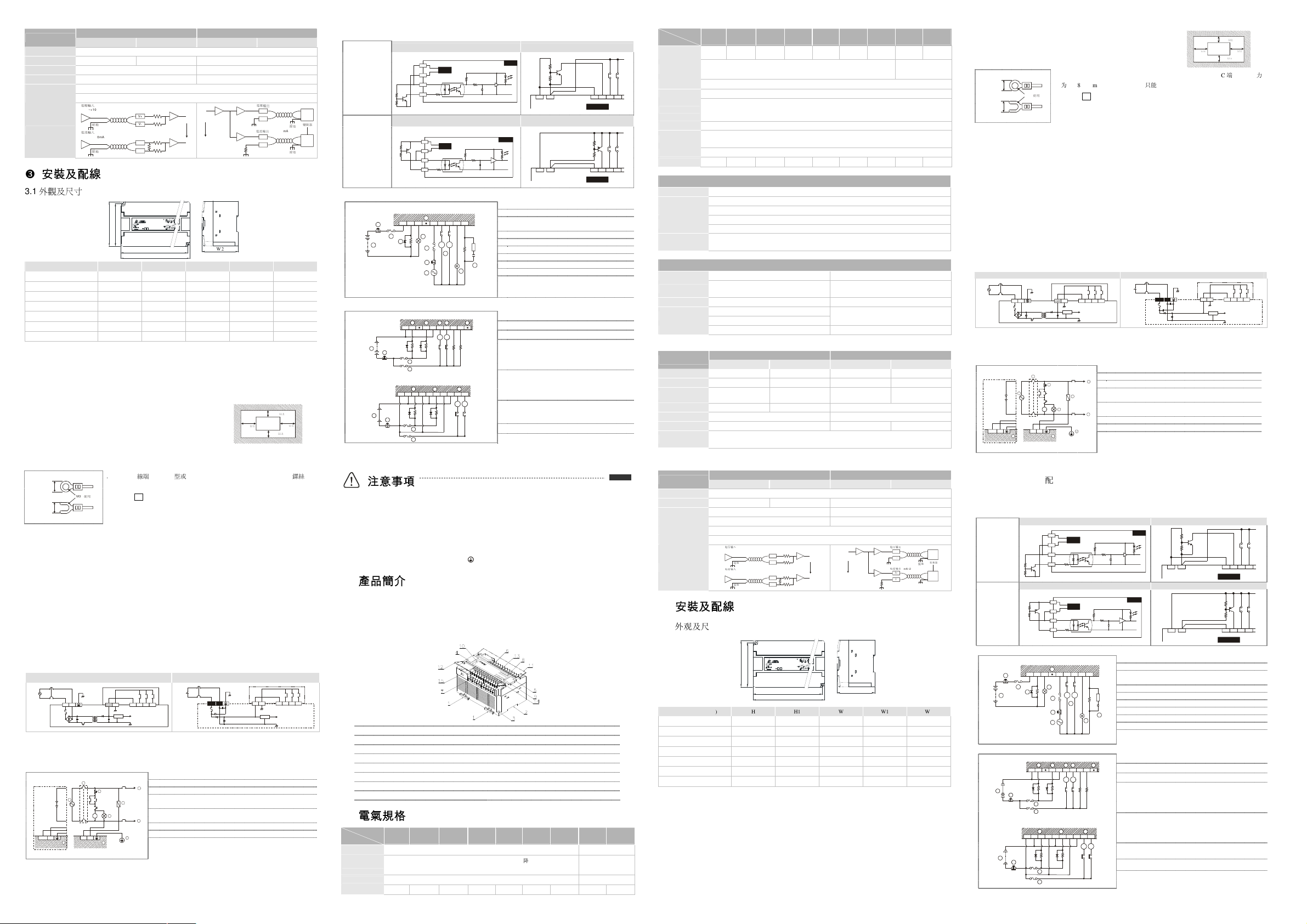
1. Please use O-type or Y-type terminals for I/O wiring terminals. The specification
Below 6.2
To suit M3.5 screw terminals
Below 6.2
tightened to between 5 ~ 8 kg-cm (4.3 ~ 6.9 in-lbs). Only can use 60/75
conducting wire.
2. DO NOT wire to the No Function terminals • . I/O signal wires or power supply
should not run through the same multi-wire cable or conduit.
3. When tightening the screws and performing the wiring, please avoid that metallic
particles fell into PLC. After completing wiring, please remove the label which is
used to obstruct the metallic particles on the ventilation hole for well heat
dissipation.
3.3 Wiring Notes
Power Input Wiring
There are two power inputs provided in DVP series PLC, AC input and DC input. Please pay particular attention
to the following notes:
1. Connect the AC input (100 ~ 240V AC) to terminals L and N. Any AC110V or AC220V connected to the
+24V terminal or input points will permanently damage the PLC.
2. The AC power inputs for the MPU and the I/O Expansion Unit should be ON or OFF at the same time.
3. Please use wires of 1.6mm or above for the grounding of the MPU.
4. If the power-cut time is less than 10ms, the PLC still operates unaffectedly. If the power-cut time is too long
or the power voltage drops, the PLC will stop operating and all the outputs will be OFF. Once the power is
restored, the PLC will return to operate automatically. (There are latched auxiliary relays and registers
inside of the PLC, please be aware when programming.)
5. The +24V supply output is rated at 0.4A from MPU. DO NOT connect external power supply to this terminal.
Moreover, it takes 5 ~ 7mA to drive each input point, so total of 100mA is needed for 16 input points. As a
result, the output loads of +24V should not exceeds 300mA.
6. When DC voltage is supplied to the PLC, ensure the power is at terminals 24V DC and 0V (power range is
20.4 ~ 26.4V DC). When the voltage is lower than 17.5V DC, PLC will stop operating, all outputs will turn
OFF and the ERROR LED will flash continuously.
100~240 VAC
2.0A
L
N
AC Input Type
S/S X0 X1 X2
24G
5V
DC/DC
20VDC~ 26VD C
2.5A
DC Input Type
OV24VDC
S/S X0 X1 X2+24V 24G
5V
DC/DC
Safety Wiring
Since the PLC is in control of numerous devices, operation of either one device could affect the operation of
other devices, therefore the breakdown of either one device would consequently be detrimental to the whole
auto control system, and danger will thus be resulted. Please use the recommended wiring below for the
power input:
OV24VDC
5
8
Guard
Limit
MC
MC
L
6
Power supply for AC loads
Fuse for circuit protection (3A Limit)
Power On pilot indicator
Emergency stop: PLC must provide a quick manual method to
disconnect all system power.
Circuit isolation device (System Power Disconnect): Use the
electromagnetic contactor and the relay as the isolation unit of the
power circuit to prevent the possible instability of the system when
the power is supplied on and off.
7
DVP PLC MPU (main processing unit)
Grounding resistance: 100Ω or less
Power supply: AC: 100 ~ 240V AC, 50/60Hz, DC: 24V DC
繁体中文
繁体中文
繁体中文繁体中文
本使用說明書僅提供電氣規格、功能規格、安裝配線部份說明,其他詳細之程式設計及指令與 SS 系列相容,
詳細說明請見 DVP-PLC 應用技術手冊【程式篇】,選購之周邊裝置詳細說明請見該產品隨機手冊。
本機為開放型 (OPEN TYPE) 機殼,因此使用者使用本機時,必須將之安裝於具防塵、防潮及免於電擊/衝擊
意外之外殼配線箱內。另必須具備保護措施(如:特殊之工具或鑰匙才可打開)防止非維護人員操作或意外
衝擊本體,造成危險及損壞。
交流輸入電源不可連接於輸入/出信號端,否則可能造成嚴重損壞,請在上電之前再次確認電源配線。請勿
在上電時觸摸任何端子。本體上之接地端子
務必正確的接地,可提高產品抗雜訊能力。
謝謝您採用台達 DVP-ES/EX 系列可程式控制器。ES/EX 系列提供 14 ~ 60 點數的主機及 8 ~ 32 點擴充,含主機最
大輸入/輸出擴充分別可達 128 點。另依主機輸入/輸出點數、電源、數位輸入/輸出擴充各類型,滿足各種應用場
合。
產品外觀及各部介紹
1. DIN 軌固定扣 9. 輸入/輸出點指示燈
2. DIN 軌糟 (35mm) 10. 電源、運行及錯誤指示燈
3. 直接固定孔 11. 輸出/入端子蓋
4. 程式通訊輸出/入口 (RS-232C) 12. 輸出/入端子蓋
5. 擴充機連介面 13. 輸出/入端子銘板
6. 輸出/入端子 14. 輸出/入端子銘板
7. 輸出/入端子 15. RS-485 通訊口
8. 輸入/輸出點指示燈
機種
項目
電源電壓
動作規格
電源保險絲容量
消耗電力
DVP-
DVP-
DVP-
DVP-
DVP-
DVP-
DVP-
14ES00□
24ES00□
30ES00□
32ES00□
40ES00□
60ES00□
100 ~ 240V AC (-15% ~ 10%), 50/60Hz ± 5%
當電源緩升至 95 ~ 100V AC 時,PLC 開始動作,當電源緩降至 70V AC 時,
PLC 會停止動作。電源瞬間斷電 10ms 以內繼續運行
20EX00□
DVP-
24ES11□
24V DC (-
電源瞬間斷電 5ms 以內
繼續運行
2A/250V AC 2A/250V AC
20VA 25VA 30VA 30VA 30VA 35VA 30VA 6.5W 8W
DVP-
20EX11□
Model
Item
Power
Protection
Voltage
Withstand
Insulation
Resistance
Noise Immunity
Grounding
Environment
Vibration /
Shock
Resistance
Weight (g) 400 552 580 580 596 750 536 414 386
Input Point Type
14ES00□
24ES00□
30ES00□
32ES00□
40ES00□
60ES00□
20EX00□
24ES11□
DC24V output short circuit DC24V input polarity
1,500 VAC (Primary-secondary), 1,500V AC (Primary-PE), 500V AC (Secondary-PE)
> 5 MΩ at 500V DC (Between all inputs/outputs and earth)
ESD: 8KV Air Discharge
EFT: Power Line: 2KV, Digital I/O: 1KV, Analog & Communication I/O: 250V
RS: 26MHz ~ 1GHz, 10V/m
The diameter of grounding wire cannot be smaller than the wire diameter of terminals L and N (All DVP
units should be grounded directly to the ground pole).
Operation: 0°C ~ 55°C (temperature), 50 ~ 95% (humidity), Pollution degree2
Storage: -25°C ~ 70°C (temperature), 5 ~ 95% (humidity)
Standard: IEC61131-2, IEC 68-2-6 (TEST Fc)/IEC61131-2 & IEC 68-2-27 (TEST Ea)
Input Point Electrical Specifications
Digital Input
Input Type DC (SINK or SOURCE)
Input Current 24VDC 5mA
Active Level
(Analog input resolution)
Reaction Time
(Conversion Sampling Time)
Output Point Type Relay-R Transistor-T
Current Specification 2A/1 point (5A/COM)
Voltage Specification Below 250V AC, 30V DC 30V DC
Maximum Load
Reaction Time About 10ms
Off → On, X0, X1: 18.5V DC and above
X2 ~ X43: 16.5V DC and above
On → Off, X0 ~ X43 below 8V DC
About 10ms (An adjustment range of 0 ~ 15ms could be selected through D1020 and
D1021)
Output Point Electrical Specifications
55°C 0.1A/1point, 50°C 0.15A/1 point
45°C 0.2A/1 point, 40°C 0.3A/1 point (2A/COM)
75VA (Inductive)
90W (Resistive)
9W/1 point
Off → On 20us, On → Off 30us
AD/DA Specifications
Analog Input (A/D) Analog Output (D/A)
Voltage Input Current Input Voltage Output Current Output
-512 ~ +511 -512 ~ +511 0 ~ 255 0 ~ 255
10 bits
= 19.53125 mV)
(1
LSB
(1
= 39.0625 µA)
LSB
10 bits
(1
= 39.0625 mV)
LSB
8 bits
- 1KΩ~2MΩ 0~500Ω
±15V ±32 mA -
DVP-1000070-01
Items
Analog I/O Range ±10V ±20mA 0 ~ 10V 0 ~ 20mA
Digital Conversion
Range
Resolution
Input Impedance > 112 KΩ 250Ω -
Output Impedance - 0.5Ωor lower
Tolerance Carried
Impedance
Overall Accuracy
Reaction Time 2ms × channels
Absolute Input Range
Digital Data Format
Average Function Provided -
Non-linear accuracy: ±0.5% of full scale within the range of PLC operation temperature
Maximum deviation: ±1% of full scale at 20mA and +10V
2’s complementary of 16-bit, 10 Significant Bits 2’s complementary of 16-bit, 8 Significant Bits
This Instruction Sheet only provides descriptions for electrical specifications, general specifications, installation &
wiring. For detailed information on programming and instructions, please refer to “DVP-PLC Application Manual:
Programming”. For more information about the optional peripherals, please see individual product instuction shee.
This is an OPEN TYPE PLC. The PLC should be kept in an enclosure away from airborne dust, humidity, electric
shock risk and vibration. Also, it is equipped with protective methods such as some special tools or keys to open the
enclosure, in order to prevent hazard to users or damage the PLC.
Do NOT connect the AC main circuit power supply to any of the input/output terminals, or it may damage the PLC.
Check all the wiring prior to power up. To prevent any electromagnetic noise, make sure the PLC is properly
grounded
. Do NOT touch terminals when power on.
ENGLISH
Thank you very much for choosing Delta’s DVP-ES/EX series PLC. DVP-ES/EX series provides MPU with 14 ~
60 points and 8 ~ 32 points of extension. The maximum I/O points including those on the MPU can reach 128
points. DVP-ES/EX can be used for various applications with its different I/O points, power supply and digital I/O
extension modules.
Product Profile and Outline
1. DIN rail clip 9. Input/Output
2. DIN rail (35mm) 10. Status indicators: POWER, RUN, and ERROR
3. Direct mounting holes 11. Input/Output terminal cover
4. Communication Ports Cover (RS-232C) 12. Input/Output terminal cover
5. Extension port indicators 13. Input/Output terminal nameplate panel
6. Input/Output terminals 14. Input/Output terminal nameplate panel
7. Input/Output terminals 15. RS-485 communication port
8. Input / Output indicators
DVP-
DVP-
DVP-
DVP-
DVP-
DVP-
DVP-
DVP-
Model
Item
Power Supply
Voltage
Operation
Specification
Fuse 2A/250V AC 2A/250V AC
Power
Consumption
DC24V Supply
Current
14ES00□
24ES00□
30ES00□
32ES00□
40ES00□
60ES00□
20EX00□
24ES11□
100 ~ 240V AC (-15% ~ 10%), 50/60Hz ± 5%
The PLC start to operate at power supply of 95 ~ 100V AC. If the voltage of
power supply drops to 70V AC, the PLC will stop. Maximum power loss time is
10ms or less.
Maximum power loss
20VA 25VA 30VA 30VA 30VA 35VA 30VA 6. 5W 8W
400mA 400mA 400mA 400mA 400mA 400mA 400mA - -
DVP-
20EX11□
24V DC (-15% ~
10%)
time is 5ms or less.
Items
Isolation Method Isolation between digital area and analog area. But no isolation among channels.
Protection
External Wiring
3.1 Dimensions
Model Name (mm) H H1 W W1 W2
DVP14ES00R2/T2 100 95 99 104 82
DVP24ES00[11]R2/T2 100 95 150 155 82
DVP30ES00R2/T2 100 95 150 155 82
DVP32ES00R2/T2 100 95 150 155 82
DVP40ES00R2/T2 100 95 150 155 82
DVP60ES00R2/T2 90 85.5 180.5 185 89.6
DVP20EX00[11]R2/T2 100 95 150 155 82
3.2 Mounting & Installation
DIN rail installation:
The DVP-PLC can be secured to a cabinet by using the DIN rail that is 35mm high with a depth of 7.5mm.
When mounting the PLC on the DIN rail, make sure to use the end bracket to stop any side-to-side motion of
the PLC; thus to reduce the chance of the wires being pulled loose. On the bottom of the PLC is a small
retaining clip. To secure the PLC to the DIN rail, place it onto the rail and gently push up on the clip. To remove
it, use a slotted screwdriver, place it on the groove of the retaining clip and press gently, then pull down on the
retaining clip and gently pull the PLC away from the DIN rail.
For heat dissipation, make sure to provide a minimum clearance of 50mm
between the unit and all sides of the cabinet. (See the figure.)
Direct mounting: Use the specified dimensions and install with M4 screws.
Analog Input (A/D) Analog Output (D/A)
Voltage Input Current Input Voltage Output Current Output
Voltage output has short circuit protection but a long period of short circuit may cause internal
wire damage and current output break.
-10V~ +10V
Grou nding
Curre nt inpu t
-20m A~+20 mA
Grou nding
56K
V+
V-
56K
28K
I+
250
I-
DVP
CH0
CH0
CH1
CH3
Curre nt outpu t
0V~10 V
V+
V-
Ground ing
0mA~20 mA
I+
I-
Ground ing
W1
> 50mm
> 50mm> 50mm
> 50mm
AC drive
Input / Output Point Wiring
The input signal of the input point is the DC power DC input. There are two types of DC type wiring: SINK and
SOURCE, defined as follows:
◎ Wiring
Input Point Loop Equivalent Circuit Wiring Loop
+24V
DC Type
(DC Signal IN)
SINK Mode
24VDC
24G
S/S
X0
Input Point Loop Equivalent Circuit Wiring Loop
DC Type
(DC Signal IN)
SOURCE Mode
+24V
24VD C
24G
S/S
X0
◎ Practical Relay Output Wiring
C0 Y0 Y1 C1 Y4 Y5 Y6 Y7
2
3
9
1
6
MC2
◎ Practical Transistor Output Wiring
Type1:
C0 Y0 Y1 C1 Y4 Y 5 Y6 Y7
1
2
3
Type2:
1
3
Zp0
Up0
2
MC2
4
Zp1
Zp2
Up1
Up2
Y4
Y1
Y0
3
Y3
SINK
+5V
+24V
24G
SOUR CE
+5V
+24V
Surge absorbing diode: increases relay contact life
Emergency stop: use an external switch
Fuse: use the fuse with a 5 ~ 10A capacity at the
common end of the output contact to protect the
output circuit.
Surge absorber: reduces noise on AC inductive loads
Unused terminal: do not connect
DC supply
Indicator: neon indicator
AC supply
Incandescent lamp (resistive loading)
Mutually exclusive outputs: use external hardware
interlocks, as well as those in the PLC program, for
maximum safety.
DC supply
Emergency stop
Fuse for circuit protection
As all outputs of the transistor modules are Open
Collectors, if the setting of Y0 is pulse train output
(using PLSY instruction), its pull-up resistor must
remain an output current of greater than 0.1A for
normal operation of the transistor modules.
As all outputs of the transistor modules are Open
Collectors, if the setting of Y1 is pulse train output
(using PWM instruction), its pull-up resistor must
remain an output current of greater than 0.1A for
normal operation of the transistor modules.
Mutually exclusive outputs: use external hardware
interlocks, as well as those in the PLC program, for
maximum safety.
Unused terminal: do not connect
Type 2 is only applicable to 30ES00T2.
24G
機種
項目
DC24V
供應電流
電源保護 DC24V 輸出具短路保護
DVP-
DVP-
DVP-
DVP-
DVP-
DVP-
DVP-
14ES00□
24ES00□
30ES00□
32ES00□
40ES00□
60ES00□
20EX00□
DVP-
24ES11□
20EX11□
400mA 400mA 400mA 400mA 400 mA 400mA 400mA - -
具直流輸入電源極性
反接保護
DVP-
突波電壓耐受量 1,500V AC (Primary-secondary)、1,500V AC (Primary-PE)、500V AC (Secondary-PE)
絕緣阻抗
5MΩ 以上(所有輸 出/入點對地之間 500V DC)
ESD: 8KV Air Discharge
X0
雜訊免疫力
接地 接地配線之線徑不得小於電源端 L, N 之線徑( 多台 PLC 同時使用時,請 務必單點接地)
操作/儲存環境
耐振動/衝擊
重量(約,g)
X0
輸入點類型 數位輸入
EFT: Power Line: 2KV, Digital I/O: 1KV, Analog & Communication I/O: 250V
RS: 26MHz ~ 1GHz, 10V/m
操作:0°C ~ 55°C(溫度),50 ~ 95%(濕度)污染等級 2
儲存:-25°C ~ 70°C (溫度),5 ~ 95%(濕度)
國際標準規範 IEC61131-2, IEC 68-2-6 (TEST Fc)/IEC61131-2 & IEC 68-2-27 (TEST Ea)
400 552 580 580 59 6 750 536 414 386
輸 入 點 電 氣 規 格
輸入形式 直流(SINK 或 SOURCE)
輸入電流
動作位准(模擬
輸入解析度)
反應時間(轉換
取樣時間)
24V DC 5mA
Off → On,X0、X1:18.5V DC 以上,X2 ~ X43:16.5V DC 以上
On → Off,8V DC 以下
約 10ms(由 D1020 及 D1021 可作 0 ~ 15ms 的調整)
輸 出 點 電 氣 規 格
輸出點形式 繼電器-R 電晶體-T
電流規格 2A/1 點(5A/COM)
電壓規格 250V AC,30V DC 以下
最大負載
75VA(電感性)
90W(電阻性)
55°C 0.1A/1 點、50°C 0.15A/1 點
45°C 0.2A/1 點、40°C 0.3A/1 點(2A/COM)
30VDC
9W/1 點
反應時間 約 10 ms Off → On 20us,On → Off 30us
AD/DA 規格
項目
模擬輸入/輸出範圍
數位轉換範圍
解析度
輸入阻抗 112 KΩ 以上
(1
輸出阻抗
容許負載阻抗
總和精密度
模擬輸入 (A/D) 模擬輸出 (D/A)
電壓輸入 電流輸入 電壓輸出 電流輸出
±10V ±20mA 0 ~ 10V 0 ~ 20mA
-512 ~ +511 -512 ~ +511 0 ~ 255 0 ~ 255
10 bits
= 19.53125 mV)
LSB
10 bits
(1
= 39.0625 µA)
LSB
250Ω -
(1
= 39.0625 mV)
LSB
8 bits
(1
LSB
- 0.5Ωor lower
- 1KΩ ~ 2MΩ 0 ~ 500Ω
非線性精度:±1%在整個溫度範圍內滿刻度時
最大誤差: ±1%在滿刻度 20mA 及+10V 時
8 bits
= 78.125µA)
Page 2
項目
CH3
56K
56K
28K
28K
250
0mA~20m A
W2
H
H
1
W
S/S
24G
DC/DC
S/S
DC/DC
1
1
2
3
4
6
Sink Ty pe
X1X2S/S
Sourc e Type
X1X2S/S
5
4
5
4
676
5
MC1
MC2
6
3
28K
W2
H
W
S/S
24G
DC/DC
S/S
DC/DC
1
1
2
3
4
6
Sink Ty pe
X1X2S/S
Sourc e Type
5
MC1
MC2
10
7
4
3
8
2
5
MC1
4
676
5
MC1
6
3
模擬輸入 (A/D) 模擬輸出 (D/A)
電壓輸入 電流輸入 電壓輸出 電流輸出
回應時間 2ms × 通道數
絕對輸入範圍
±15 V ±32 mA -
數位資料格式 16 位 2 補數(有效位 10 bits) 16 位 2 補數(有效位 8 bits)
平均功能 是
-
隔離方式 數位及類比電路間未隔離
保護 電壓輸出有短路保護但須注意長時間短路仍有可能造成內部線路損壞,電流輸出可開路。
外部配線圖
電壓輸入
-10V~+1 0V
接地
電流輸入
-20mA~+ 20mA
接地
電壓輸出
0V~10V
電流輸出
V+
V-
I+
I-
變頻器
接地
接地
V+
V-
I+
I-
CH0
CH0
CH1
3.1 外觀及尺寸
DVP
W1
機 種 型 號 (mm)
H H1 W W1 W2
DVP14ES00R2/T2 100 95 99 104 82
DVP24ES00[11]R2/T2 100 95 150 155 82
DVP30ES00R2/T2 100 95 150 155 82
DVP32ES00R2/T2 100 95 150 155 82
DVP40ES00R2/T2 100 95 150 155 82
DVP60ES00R2/T2 90 85.5 180.5 185 89.6
DVP20EX00[11]R2/T2 100 95 150 155 82
3.2 盤內安裝及配線
DIN 鋁軌之安裝方法:適合 35mm 之 DIN 鋁軌,主機欲掛于鋁軌時,先將主機(或擴充機)下方之固定塑膠片壓
入,再將主機(或擴充機)由上方掛上再往下壓即可。欲取下主機時,主機背面下之固定塑膠片,以一字形起子
插入凹槽,向上撐開即可,該固定機構塑膠片為保持型,因此該固定片撐開後便不會彈回去,當所有的固定片撐
開後,再將主機往上外方取出。
PLC 在安裝時,請裝配於封閉式之控制箱內,其周圍應保持一定之空間(如
右圖所示),以確保 PLC 散熱功能正常。
直接鎖鏍絲方式:請依產品外型尺寸並使用 M4 鏍絲。
50mm
以上
DVP MPU
50mm
50mm
以上
以上
50mm
以上
◎ 配線
直流形式
(DC Signal IN)
SINK 模式
直流形式
(DC Signal IN)
SOURCE 模式
◎實用之繼電器輸出回路配線
C0 Y 0 Y1 C1 Y4 Y5 Y6 Y7
2
3
1
6
◎實用之電晶體輸出回路配線
型式一:
C0 Y0 Y1 C1 Y4 Y 5 Y6 Y7
1
2
3
3
型式二:
1
4
Zp0
Up0
Y0
2
3
輸入點回路等效電路 配線回路
+24V
24VDC
24G
S/S
X0
SINK
+5V
+24V
24G
輸入點回路等效電路 配線回路
+24V
24VD C
24G
S/S
X0
9
MC2
MC1
3
10
2
8
7
MC2
MC1
Zp1
Zp2
Up1
Up2
Y4
Y1
Y3
SOUR CE
+5V
+24V
突波吸收二極體:可增加接點壽命
緊急停止:使用外部開關
保險絲:使用 5~10A 的保險絲容量於輸出接點的共用
點,保護輸出點回路。
突波吸收器:可減少交流負載上的雜訊
空端子:不使用
直流電源供給
指示燈:氖燈
交流電源供給
白熾燈(電阻性負載)
互斥輸出:利用外部電路形成互鎖,配合 PLC 內部
程式,確保任何異常突發狀況發生時,均有安全的保
護措施。
直流電源供應
緊急停止
電路回路保護用保險絲
因電晶體模組輸出均為開集極輸出(Open
Collector),若 Y0 設定為 脈波串輸出(使用 P LSY 指
令),為確保電晶體模組能夠動作正常,其輸出提升
電阻,必須維持輸出電流大於 0.1A。
因電晶體模組輸出均為開集極輸出(Open
Collector),若 Y1 設定為 脈波串輸出(使用 PWM 指
令),為確保電晶體模組能夠動作正常,其輸出提升
電阻,必須維持輸出電流大於 0.1A。
互斥輸出:利用外部電路形成互鎖,配合 PLC 內部
程式,確保任何異常突發狀況發生時,均有安全的保
護措施。
空端子:不使用
型式二只適用於 30E S00T2 機種
24G
机种
项目
DC24V
供应电流
电源保护 DC24V 输出具短路保护
突波电压耐受量
X0
绝缘阻抗 5 MΩ 以上(所有输出/入点对地之间 500VDC)
噪声免疫力
接地 接地配线之线径不得小于电源端 L, N 之线径(多台 PLC 同时使用时,请务必单点接地)
操作/储存环境
耐振动/冲击 国际标准规范 IE C61131-2, IEC 68-2-6 (TEST Fc)/IEC61131-2 & IEC 68-2-27 (TEST Ea)
X0
重量(约,g) 400 552 580 580 596 750 536 414 386
输入点类型 数字输入
输入形式 直流(SINK 或 SOURCE)
输入电流 24V DC 5mA
动作位准
反应时间
(转换取样时间)
输出点形式 继电器-R 晶体管-T
电流规格 2A/1 点 (5A/COM)
电压规格 250V AC, 30V DC 以下 30V DC
最大负载
反应时间 约 10 ms Off → On 20us,On → Off 30us
AD/DA 规格
模拟输入/输出范围
数字转换范围 -512 ~ +511 -512 ~ +511 0 ~ 255 0 ~ 255
分辨率
输入阻抗 112 KΩ 以上 250Ω -
输出阻抗 - 0.5Ωor lower
容许负载阻抗 - 1KΩ ~ 2MΩ 0 ~ 500Ω
总和精密度
DVP-
DVP-
DVP-
DVP-
DVP-
DVP-
14ES00□
24ES00□
30ES00□
32ES00□
40ES00□
60ES00□
DVP-
20EX00□
400mA 400mA 400mA 400mA 400mA 400mA 400mA - -
1,500V AC (Primary-secondary),1,500V AC (Primary-PE),500VAC (Secondary-PE)
ESD: 8KV Air Discharge
EFT: Power Line: 2KV, Digital I/O: 1KV, Analog & Communication I/O: 250V
RS: 26MHz ~ 1GHz, 10V/m
操作:0°C ~ 55°C (温度),50 ~ 95%(湿度),污染等级 2
储存:-25°C ~ 70°C (温度),5 ~ 95%(湿度)
输 入 点 电 气 规 格
Off → On,X0、X1:18.5V DC 以上,X2 ~ X43:16.5V DC 以上
On → Off,8V DC 以下
约 10ms(由 D1020 及 D1021 可作 0 ~ 15ms 的调整)
输 出 点 电 气 规 格
55°C 0.1A/1 点、50°C 0.15A/1 点
45°C 0.2A/1 点、40°C 0.3A/1 点 (2A/COM)
75VA(电感性)
90 W(电阻性)
项目
模拟输入 (A/D) 模拟输出 (D/A)
电压输入 电流输入 电压输出 电流输 出
±10V ±20mA 0 ~ 10V 0 ~ 20mA
10 bits
(1
= 19.53125 mV)
LSB
10 bits
(1
= 39.0625µA)
LSB
非线性精度:±1%在整个温度范围内满刻度时
最大误差: ±1%在满刻度 20mA 及+10V 时
(1
LSB
8 bits
= 39.0625mV)
DVP-
24ES11□
具直流输入电源极性反
9W/1 点
(1
LSB
DVP-
20EX11□
接保护
8 bits
= 78.125µA)
50mm
PLC 在安装时,请装配于封闭式之控制箱内,其周围应保持一定之空间(如
右图所示),以确保 PLC 散热功能正常。
直接锁镙丝方式:请依产品外型尺寸并使用 M4 镙丝。
50mm
以上
DVP MPU
50mm
以上
以上
50mm
以上
1. 出/入配线端请使用 O 型或 Y 型端子,端子规格如左所示。PLC 端子镙丝扭力
6.8mm
6.8mm
以下
M3.5
以下
为 5 ~ 8 kg-cm (4.3 ~ 6.9 in-lbs)。只能使用 60/75°C 的铜导线。
使用
2. 空端子 • 请勿配线。输入点信号线与输出点等动力线请勿置于同一线糟内。
3. 锁镙丝及配线时请避免微小的金属导体掉入 PLC 内部,并在配线完成后,将位
于 PLC 上方散热孔位置的防异物掉入之贴纸撕去,以保持散热良好。
3.3 注意事项
电源端配线及规格
DVP 系列 PLC 电源输入分为交流输入及直流输入两种,在使用上应注意下列事项:
1. 交流电源输入电压,范围宽广(100 ~ 240V AC),电源请接于 L、N 两端,如果将 AC110V 或 AC220V 接至
+24V 端或输入点端,将使 P LC 损坏,请使用者特别注意。
2. 主机及 I/O 扩展机之交流电源输入请同时作 On 或 Off 的动作。
3. 主机之接地端使用 1.6mm 以上之电线接地。
4. 当停电时间低于 10ms 时,PLC 不受影响继续运行,当停电时间过长或电源电压下降将使 PLC 停止运行,输
出全部 O ff,当电源恢复正常时,PLC 亦自动回复运行。(PLC 内部具有停电保持的辅助继电器及寄存器,使
用者在作程序设计规划时应特别注意使用。)
5. +24V 电源供应输出端,最大为 0.4A,请勿将其它的外部电源连接至此端子。每个输入点驱动必须 5 ~ 7mA,
若以 16 点输入计算,大约需 100mA,因此+24V 输出给外部负载不可大于 300mA。
6. 当 PLC 为直流电源输入时,电源请接于 24V DC 及 0V 两端,电源范围为 20.4 ~ 26.4V DC,当电源电压低于
17.5V DC 时,PLC 会停止运行,输出全部 Off,ERROR LED 快速闪烁。
交流电源输入型式 直流电源输入型式
100~240VAC
L
N
2.0A
X0 X1 X2
5V
20VDC~26V DC
OV24VDC
2.5A
X0 X1 X 2+24V 2 4G
5V
安全配线回路
由于 P LC 控制许多装置,任一装置的动作可能都会影响其它装置的动作,因此任一装置的故障都可能会造成整
个自动控制系统失控,甚至造成危险。所以在电源端输入回路,建议配置如下的保护回路:
5
8
Guard
Limit
MC
MC
OV24VDC
NL
6
交流电源负载
电源回路保护用保险丝(3A)
电源指示灯
紧急停止:为预防突发状况发生,设置一紧急停止按钮,可在状
况发生时,切断系统电源。
系统回路隔离装置:使用电磁接触器、继电器等开关作为系统电
源回路隔离装置,可防止电源断续供应时,造成系统的不稳定。
DVP PLC 本体
接地阻抗 100Ω 以下
7
电源供应:
交流(AC):100 ~ 240VAC, 50/60Hz
直流(DC):24V DC
6.8mm
6.8mm
以下
M3.5
以下
為 5 ~ 8 kg-cm (4.3 ~ 6.9 in-lbs)。只能使用 60/75°C 的銅導線。
使用
2. 空端子 • 請勿配線。輸入點信號線與輸出點等動力線請勿置於同一線糟內。
3. 鎖鏍絲及配線時請避免微小的金屬導體掉入 PLC 內部,並在配線完成後,將位
於 PLC 上方散熱孔位置的防異物掉入之貼紙撕去,以保持散熱良好。
3.3 注意事項
電源端配線及規格
1. 出 /入配線端請使用 O 型或 Y 型端子,端子規格如左所示。PLC 端子鏍絲扭力
DVP 系列 PLC 電源輸入分為交流輸入及直流輸入兩種,在使用上應注意下列事項:
1. 交流電源輸入電壓,範圍寬廣 (100 ~ 240V AC),電源請接於 L、N 兩端,如果將 AC110V 或 AC220V 接至+24V
端或輸入點端,將使 PLC 損壞,請使用者特別注意。
2. 主機及 I/O 擴充機之交流電源輸入請同時作 On 或 Off 的動作。
3. 主機之接地端使用 1.6mm 以上之電線接地。
4. 當停電時間低於 10ms 時,PLC 不受影響繼續運轉,當停電時間過長或電源電壓下降將使 PLC 停止運轉,輸
出全部 Off,當電源恢復正常時,PLC 亦自動回復運轉。(PLC 內部具有停電保持的輔助繼電器及暫存器,使
用者在作程式設計規劃時應特別注意使用。)
5. +24V 電源供應輸出端,最大為 0.4A,請勿將其他的外部電源連接至此端子。每個輸入點驅動必須 5 ~ 7mA,
若以 16 點輸入計算,大約需 100mA,因此+24V 輸出給外部負載不可大 300mA。
6. 當 PLC 為直流電源輸入時,電源請接於 24V DC 及 0V 兩端,電源範圍為 20.4 ~ 26.4V DC,當電源電壓低於
17.5V DC 時,PLC 會停止運轉,輸出全部 Off,ERROR LED 快速閃爍。
交流電源輸入型式 直流電源輸入型式
100~240VAC
L
N
2.0A
X0 X1 X2
5V
20VDC~26V DC
OV24VDC
2.5A
X0 X1 X2+24V 24G
5V
安全配線回路
由於 PLC 控制許多裝置,任一裝置的動作可能都會影響其他裝置的動作,因此任一裝置的故障都可能會造成整
個自動控制系統失控,甚至造成危險。所以在電源端輸入回路,建議配置如下的保護回路:
交流電源負載
5
8
Guard
Limit
MC
OV24VDC
NL
6
電源回路保護用保險絲(3A)
電源指示燈
緊急停止:為預防 突發狀況發生 ,設置一緊急停止 按鈕,可在狀
況發生時,切斷系統電源。
系統回路隔離裝 置:使用電磁接觸 器、繼電器等 開關作為系統電
MC
7
源回路隔離裝置,可防止電源斷續供應時,造成系統的不穩定。
DVP PLC 本體
接地阻抗 100Ω 以下
電源供應:
交流(AC):100 ~ 240V AC, 50/60Hz
直流(DC):24V DC
輸入/輸出點之配線
輸入點之入力信號為直流電源 DC 輸入,DC 型式共有兩種接法:SINK 及 SOURCE,其定義如下:
◎ DC 型式。DC 型式共有兩種接法,SINK 及 SOURCE,其定義如下:
本使用说明书仅提供电气规格、功能规格、安装配线部份说明,其它详细之程序设计及指令与 SS 系列兼容,
详细说明请见 DVP-PLC 应用技术手册【程序篇】,选购外围装置详细说明请见该产品随机手册。
本机为开放型 (OPEN TYPE) 机壳,因此使用者使用本机时,必须将之安装于具防尘、防潮及免于电击/冲
击意外之外壳配线箱内。另必须具备保护措施(如:特殊之工具或钥匙才可打开)防止非维护人员操作或意
外冲击本体,造成危险及损坏。
交流输入电源不可连接于输入/出信号端,否则可能造成严重损坏,请在上电之前再次确认电源配线。请勿
在上电时触摸任何端子。本体上之接地端子
务必正确的接地,可提高产品抗噪声能力。
谢谢您采用台达 D VP-ES/EX 系列可编过程控制器。ES/EX 系列提供 14 ~ 60 点数的主机及 8 ~ 32 点扩展,含主机
最大输入/输出扩展分别可达 128 点。另依主机输入/输出点数、电源、数字输入/输出扩展各类型,满足各种应用
场合。
产品外观及各部介绍
1. DIN 轨固定扣 9. 输入 / 输出点指示灯
2. DIN 轨糟(35mm) 10. 电源、运行及错误指示灯
3. 直接固定孔 11. 输出/入端子盖
4. 程序通讯输出/入口(RS-232C) 12. 输出/入端子盖
5. 扩展机连接口 13. 输出/入端子铭板
6. 输出/入端子 14. 输出/入端子铭板
7. 输出/入端子 15. RS-485 通讯口
8. 输入/输出点指示灯
机种
项目
电源电压
动作规格
电源保险丝容量
消耗电力 20VA 25VA 30VA 30VA 30VA 35VA 30VA 6.5W 8W
DVP-
DVP-
DVP-
DVP-
DVP-
14ES00□
24ES00□
30ES00□
32ES00□
40ES00□
DVP-
60ES00□
20EX00□
100 ~ 240VAC (-15% ~ 10%), 50/60Hz ±5%
当电源缓升至 95 ~ 100V AC 时,PLC 开始动作,当电源缓降至 70V AC 时,PLC
会停止动作。电源瞬间断电 10ms 以内继续运行
2 /250V AC 2A/250V AC
DVP-
简体中文
简体中文
简体中文简体中文
DVP-
DVP-
24ES11□
20EX11□
24V DC (-15% ~ 10%)
电源瞬间断电 5ms 以内
继续运行
项目
模拟输入 (A/D) 模拟输出 (D/A)
电压输入 电流输入 电压输出 电流输 出
响应时间 2ms × 信道数
绝对输入范围 ±15V ±32mA -
数字资料格式 16 位 2 补码,(有效位 10 bits) 16 位 2 补码,(有效位 8 bits)
平均功能 是 -
隔离方式 数字及仿真电路间未隔离
保护 电压输出有短路保护但须注意长时间短路仍有可能造成内部线路损坏,电流输出可开路。
外部配线图
电压输 入
-10V~+10V
接地
电流输 入
-20mA~+20mA
接地
电压输出
0V~10V
电流输出
V+
V-
I+
I-
0mA~20mA
变频器
接地
56K
V+
V-
I+
I-
CH0
56K
28K
CH3
250
CH0
CH1
3.1 外观及尺寸
H1
DVP
W1
机 种 型 号 (mm) H H1 W W1 W2
DVP14ES00R2/T2 100 95 99 104 82
DVP24ES00[11]R2/T2 100 95 150 155 82
DVP30ES00R2/T2 100 95 150 155 82
DVP32ES00R2/T2 100 95 150 155 82
DVP40ES00R2/T2 100 95 150 155 82
DVP60ES00R2/T2 90 85.5 180.5 185 89.6
DVP20EX00[11]R2/T2 100 95 150 155 82
3.2 盘内安装及配线
DIN 铝轨之安装方法:
适合 3 5mm 之 DIN 铝轨,主机欲挂于铝轨时,先将主机(或扩展机)下方之固定塑料片压入,再将主机(或扩
展机)由上方挂上再往下压即可。欲取下主机时,主机背面下之固定塑料片,以一字形起子插入凹槽,向上撑开
即可,该固定机构塑料片为保持型,因此该固定片撑开后便不会弹回去,当所有的固定片撑开后,再将主机往上
外方取出。
输入/输出点之配线
输入点之入力信号为直流电源 DC 输入,DC 型式共有两种接法:SINK 及 SOURCE,其定义如下:
◎ DC 型式,DC 型式共有两种接法,SINK 及 SOURCE,其定义如下:
◎ 配线
直流形式
(DC Signal IN)
SINK 模式
直流形式
(DC Signal IN)
SOURCE 模式
◎ 实用之继电器输出回路配线
C0 Y0 Y1 C1 Y 4 Y5 Y6 Y 7
2
3
1
6
◎ 实用之晶体管输出回路配线
型式一:
1
2
型式二:
Up0
1
2
输入点回路等效电路 配线回路
+24V
24VDC
24G
S/S
X0
SINK
+5V
输入点回路等效电路 配线回路
+24V
24VD C
24G
S/S
X0
9
C0 Y0 Y1 C1 Y4 Y 5 Y6 Y7
3
3
Zp0
MC2
4
Zp1
Zp2
Up1
Up2
Y0
Y1
3
Y4
Y3
MC2
SOUR CE
+5V
突波吸收二极管:可增加接点寿命
紧急停止:使用外部开关
保险丝:使用 5~1 0A 的保险丝容量于输出接点的共享点,
保护输出点回路。
突波吸收器:可减少交流负载上的噪声
空端子:不使用
直流电源供给
指示灯:氖灯
交流电源供给
白炽灯(电阻性负载)
互斥输出:利用外部电路形成互锁,配合 PLC 内部程序,
确保任何异常突发状况发生时,均有安全的保护措施。
直流电源供应
紧急停止
电路回路保护用保险丝
因晶体管模块输出均为开集极输出(Open Collector),若 Y0
设定为脉波串输出(使用 PLSY 指令),为确保晶体管模块能
够动作 正常 ,其 输出 提升 电阻 ,必 须维 持输 出电 流大 于
0.1A。
因晶体管模块输出均为开集极输出(Open Collector),若 Y1
设定为脉波串输出(使用 PWM 指令),为确保晶体管模块能
够动作 正常 ,其 输出 提升 电阻 ,必 须维 持输 出电 流大 于
0.1A。
互斥输出:利用外部电路形成互锁,配合 PLC 内部程序,
确保任何异常突发状况发生时,均有安全的保护措施。
空端子:不使用
型式二只适用于 30E S00T2 机种
+24V
24G
X0
+24V
24G
X1 X2S/S X 0
Page 3

DVP-1000070-01
DVP-
DVP-
DVP-
DVP-
DVP-
DVP-
DVP-
Model
Madde
DC24V Besleme
Akımı
Power Koruma DC24V çıkış kısa devre DC24V giriş kutup
Dayanma Voltajı 1,500 VAC (Primary-secondary), 1,500V AC (Primary-PE) , 500V AC (Secondary-PE)
İzolasyon
Direnci
Ses Bağışıklığı
Topraklama
Ortam Koşulları
Titreşim / Şok
Direnci
Ağırlık (g) 400 552 580 580 596 750 536 414 386
Giriş Nokta Tipi
14ES00□
24ES00□
30ES00□
32ES00□
40ES00□
60ES00□
400mA 400mA 400mA 400mA 400mA 400mA 400mA - -
> 5 MΩ at 500V DC (Tüm giriş / çıkış ve toprak arasında)
ESD: 8KV Hava Boşaltmalı
EFT: Power Line: 2KV, Dijital I/O: 1KV, Analog & Haberleşme I/O: 250V
RS: 26MHz ~ 1GHz, 10V/m
Topraklama kablosu kesiti L ve N terminalleri kablosu kesitinden küçük olmamalıdır. (Tüm DVP üniteleri
toprağa doğrudan bağlanmalıdır).
Çalışma: 0°C ~ 55°C (sıcaklık), 50 ~ 95% (nem), Kirlilik derecesi2
Saklama: -25°C ~ 70°C (sıcaklık), 5 ~ 95% (nem)
Standard: IEC61131-2, IEC 68-2-6 (TEST Fc)/IEC61131-2 & IEC 68-2-27 (TEST Ea)
Giriş Noktası Elektrik Özellikleri
Dijital Giriş
20EX00□
DVP-
24ES11□
Giriş Tipi DC (SINK veya SOURCE)
Giriş Akımı 24VDC 5mA
Aktif Seviye
(Analog giriş çözünürlüğü)
Reaksiyon Zamanı
(Örnekleme Zamanı)
Çıkış Nokta Tipi Röle-R Transistör-T
Akım Özellikler 2A/1 noktada (5A/COM)
Voltaj Özellikleri Üzeri 250V AC, 30V DC 30V DC
Maksimum Yük
Reaksiyon Zamanı Yaklaşık 10ms
Off → On, X0, X1: 18.5V DC ve üstü
X2 ~ X43: 16.5V DC ve üstü
On → Off, X0 ~ X43 altı 8V DC
Yaklaşık 10ms (D1020 ve D1021 datalarından 0~15ms ayarlanabilir )
Çıkış Noktası Elektrik Özellikleri
55°C 0.1A/1 nokta, 50°C 0.15A/1 nokta
45°C 0.2A/1 nokta, 40°C 0.3A/1 nokta
(2A/COM)
75VA (Endüktif)
90W (Resistif)
9W/1 nokta
Off → On 20us, On → Off 30us
AD/DA Özellikleri
Madde
Analog I/O Aralığı ±10V ±20mA 0 ~ 10V 0 ~ 20mA
Digital Dönüşüm
Aralığı
Çözünürlük
Giriş Empedansı > 112 KΩ 250Ω Çıkış Empedansı - 0.5Ω veya altı
Tol er ans Taşıyıcı
Empedans
Tam Do ğruluk
Reaksiyon Zamanı 2ms × kanal
Mutlak Giriş Aralığı
Dijital Data Formatı
Non-linear doğruluk: PLC çalışma sıcaklığında ±0.5% tam skala.
Maksimum sapma: (1% tam skala 20mA ve +10V)
Analog Giriş (A/D) Analog Çıkış (D/A)
Voltaj Giriş Akım Giriş Volt aj Ç ıkış Akım Çıkış
-512 ~ +511 -512 ~ +511 0 ~ 255 0 ~ 255
(1
= 19.53125 mV)
LSB
10 bit
(1
= 39.0625 μA)
LSB
10 bit
(1
= 39.0625 mV)
LSB
8 bit
(1
- 1KΩ~2MΩ 0~500Ω
±15V ±32 mA -
16 bitin 2’ye tümleyeni, 10 Bit 16 bitin 2’ye tümleyeni, 8 Bit
LSB
DVP-
20EX11□
8 bit
= 78.125 μA)
9 Bu bilgi dökümanı PLC’nin genel özellikleri, elektriksel özellikleri, kurulum, bağlantı, hata tespiti ve hata giderilmesi
ile çevre donanımlar hakkında bilgi verir. Komutlar ve programlama ile ilgili daha fazla bilgi için, lütfen PLC
Uygulama manualine bakınız. Opsiyonel modüller ile ilgili daha fazla bilgi için lütfen donanımla ilgili bilgi
dökümanına veya user manualine bakınız.
9
Bu ürün AÇIK TİP bir PLC’dir. Bu nedenle toz, nem, elektrik şoku v e titreşim olmayan bir ortama kurulmalıdır. A yr ıca
cihaza müdahale edilmesini engelleyecek önlemler alınmalıdır. ( Örn eğin cihazın bulunduğu panoya kilit konulması
gibi). Aksi durumda yanlış kullanım sonucu ürün zarar görebilir.
9 Giriş/çıkış terminallerine kesinlikle AC power b ağlantısı yapmayınız, bu durum cihaza zarar verecektir. Ürüne enerji
vermeden önce bütün bağlantıları kontrol edin. Elektromanyetik gürültüden etkilenmemek için, PLC’nin düzgün
topraklandığından
emin olun. Cihazda enerji varken terminallere dokunmayınız.
Türkçe
Delta’nın DVP-ES/EX Serisi PLC’leri satın aldığınız için teşekkürler. DVP-ES/EX Serisi Merkezi işlemci ünitesi
(CPU) ve ilave üniteler sunar. CPU ünitesinde 14~60 giriş/çıkış noktası olabilirken ilave üniteler 8~32 giriş/çıkış
noktası sunar. CPU ve ilave üniteler yan yana bağlanarak maksimum 128 giriş/çıkış noktasına kadar
genişletilebilir. İlave giriş/çıkış modülleri beslemesi ayrı bağlanmalıdır.
Ürün Profili ve Taslağı
1. DIN ray klip 9. Giriş / Çıkış
2. DIN ray (35mm) 10. Durum indikatörleri: POWER, RUN, ve ERROR
3. Doğrudan montaj delikleri 11. Giriş / Çıkış terminal kapağı
4. Haberleşme port kapağı (RS-232C) 12. Giriş / Ç ıkış terminal kapağı
5. İlave port indikatörleri 13. Giriş / Çıkış terminali etiket paneli
6. Giriş / Çıkış terminalleri 14. Giriş / Çıkış terminali etiket paneli
7. Giriş / Çıkış terminalleri 15. RS-485 haberleşme portu
8. Giriş / Çıkış indikatörleri
DVP-
DVP-
DVP-
DVP-
DVP-
DVP-
DVP-
DVP-
Model
Madde
Power Kaynağı
Volt ajı
Çalışma
Özellikleri
Sigorta 2A/250V AC 2A/250V AC
Power Tüketimi 20VA 25VA 30VA 30VA 30VA 35VA 30VA 6.5W 8W
14ES00□
24ES00□
30ES00□
32ES00□
40ES00□
60ES00□
20EX00□
100 ~ 240V AC (-15% ~ 10%), 50/60Hz ± 5%
PLC 95~100VAC beslemede çalışmaya başlar. Eğer besleme voltajı 70VAC
altına düşerse, PLC duracak. Maksimum izin verilen enerji kesinti si zamanı
10ms veya altıdır.
DVP-
24ES11□
20EX11□
24V DC (-15% ~
10%)
Maksimum enerji
kesintisi zamanı 5ms
veya altıdır.
Madde
Ortalama Fonksiyonu Mevcut İzolasyon Metodu Di jital – Analog arası izolasyon. Fakat kanallar arası izolasyon yok
Koruma
Harici Bağlantı
Diyagramı
Voltaj çıkışı kısa devre korumalı fakat uzun süreli kısa devrede dahili kabloların zarar görmesine
ve akım çıkışının bozulmasına sebep olur.
Analog Giriş (A/D) Analog Çıkış (D/A)
Voltaj Giriş Akım Giriş Volt aj Ç ıkış Akım Çıkış
Voltage Input
-10V~+10V
Grounding
Current Inpu t
-20mA~+20mA
Grounding
56K
V+
V-
I+
I-
CH0
56K
28K
250
28K
CH0
CH1
CH3
Voltage Output
V+
V-
Current Output
I+
I-
0V~10V
Grounding
0mA~20mA
AC Drive
3.1 Boyutlar
H1
H
Model İsmi (mm) H H1 W W1 W2
DVP14ES00R2/T2 10 0 95 99 104 82
DVP24ES00[11]R2/T2 100 95 150 155 82
DVP30ES00R2/T2 10 0 95 150 155 82
DVP32ES00R2/T2 10 0 95 150 155 82
DVP40ES00R2/T2 10 0 95 150 155 82
DVP60ES00R2/T2 90 85.5 180.5 18 5 89.6
DVP20EX00[11]R2/T2 100 95 15 0 155 82
3.2 Montaj & Kurulum
DIN ray kurulumu:
DVP-PLC 35mm genişliğe 7.5m m derinliğe sahip DIN ray kullanılarak panoya monte edilebilir. PLC’yi DIN
raya yerleştirirken cihazın ray üzerinde hareket etmesini engellemek için bileziklerle sağdan soldan
sabitlenmelidir, böylece kabloların gevşemesi de engellenmiş olur. PLC’nin alt tarafında küçük sabitleyici bir
klip bulunmaktadır. PLC’yi DIN raya sabitlemek için, ray üzerinde iken klipi hafifçe yukarı itmeniz gerekir.
Çıkarmak için klipi aşağı doğru hafifçe ç ekebilir ve PLC’yi DIN raydan ayırabilirsiniz.
PLC’yi monte ederken fazla ısınmasını engellemek için çevresinde
aşağıdaki şekilde gösterildiği gibi min. 50 mm. boşluğun bırakıldığından
emin olun.
Doğrudan montaj:
Belirtilen ölçüleri kullanın ve M4 vida ürünü monte edin.
W1
W
W2
> 50mm
DVP MPU
> 50mm> 50mm
> 50mm
Page 4

1. O-tipi veya Y-tipi terminal kullanın. Terminal özellikleri için yandaki şekle bakınız.
PLC terminal vidaları sıkma oranı 5~8 kg-cm (4.3~6.9 in-lbs) olmalı ve bağlantıda
Below 6.2
To suit M3.5 screw terminals
Below 6.2
60/75°C bakır iletken kullanılmalıdır .
2. Boş terminallere bağlantı yapmayınız • . I/O sinyal kabloları veya güç kaynağı
aynı kablo bloğu içinden yan yana geçmemelidir
3. Vidaları sıkarken veya bağlantı yaparken küçük metal iletken parçaları PLC içine
düşürmeyin. PLC’nin ısınmasını önlemek için bağlantı sırasında havalandırma
deliklerinden metal parçaların PLC içine girmesini engelleyen etiketleri tüm
bağlantılar tamamlandıktan sonra çıkartını
z.
3.3 Kurulum Notlar
Power Giriş Bağlantısı
DVP serisi PLC’lerde iki çeşit power girişi vardır. A C gir iş veya DC giriş. Lütfen kurulum yaparken aşağıdaki
uyarılara dikkat ediniz:
1. AC power girişini (100VAC ~ 240VAC) L ve N terminallerine bağlayın. AC110V veya AC220V power girişi
+24V terminaline veya giriş noktalarına bağlanırsa PLC’de kalıcı zararlara sebep olur
2. CPU ve I/O ilave ünitelerinin AC power girişleri aynı anda ON ve ya OFF yapılmalıdır.
3. CPU topraklaması için lütfen 1.6mm veya daha büyük kablo kullanın.
4. 10ms’den daha kısa süreli bir elektrik kesintisi PLC’nin çalışmasını etkilemeyecektir. Daha uzun süreli
elektrik kesintisi veya voltaj düşüşünde PLC’nin çalışması duracak ve bütün çıkışlar OFF olacaktır.
Besleme voltajı normal seviyesine döndüğü zaman PLC otomatik olarak çalışmasına dönecektir.
(Programlama yaparken kalıcı yardımc
5. CPU üzerindeki +24V besleme çıkışı 0.4A’dir. Bu terminale harici power bağlantısı yapmayınız. Ayrıca her
bir giriş noktası aktif olması için 5~7mA gerekir. 16 giriş için bu değer yaklaşık 100 mA olur. Sonuç olarak bu
terminallere 300mA üzerinde yük bağlanmamalıdır.
6. PLC’ye DC voltaj uygulanacağı zaman, bağlantı 24VDC ve 0V terminallerine yapılmalıdır. (Besleme voltaj
aralığı 20.4VDC~26.4VDC). Voltaj 17.5VDC altına düştüğü zaman, PLC çalışması duracak, tüm çıkışlar
OFF olacak ve ERROR LED sürekli flash yapacak
AC Giriş Tipi DC Giriş Tipi
ı röle ve registerlerin kullanımına dikkat ediniz).
100~240VAC
S/S X0 X1 X2
L
N
2.0A
24G
5V
DC/DC
20VDC~26VDC
OV24VDC
2.5A
S/S X0 X1 X2+24V 24G
5V
DC/DC
Güvenli Bağlantı
PLC birçok sistemi kontrol ettiği için, sistemlerden herhangi birinin hareketi diğer sistemleri de etkiler ve bir
sistemde oluşan bir problem diğer sistemleri ve hatta tüm kontrol sisteminin bozulmasına ve tehlikelere yol
açar. Bu durumu engellemek için aşağıda gösterildiği gibi power giriş terminallerine koruma devresi bağlantısı
önerilir:
5
4
8
OV24VDC
2
Guard
Limit
MC
3
MC
NL
66
AC power besleme
c
Devre koruma sigortası (3A Limit)
d
1
Power On pilot indikator
e
Acil stop: Acil durum oluştuğunda bu buton tüm sistemin enerjisini
f
kesebilmelidir.
Sistem devresi izolasyon birimi: Sistem in enerjisi aniden kesilip
g
geldiğinde olası kararsızlığı engellemek için güç devresinde
1
elektromanyetik kontaktör ve röle kullanılarak izolasyon birimi
oluşturulabilir.
7
DVP PLC MPU (ana işlemci ünitesi)
h
Topraklama direnci: 100Ω veya altı
i
Power supply: AC: 100~240VAC, 50/60Hz, DC: 24VDC
j
Giriş / Çıkış Noktası Bağlantısı
Giriş noktasının giriş sinyali DC besleme DC girişidir. Aşağıda gösterildiği gibi iki çeşit DC bağlantı şekli vardır. SIN K ve
SOURCE:
◎ Bağlantı
DC Tip
(DC Sinyal IN)
SINK Mod
DC Tipi
(DC Sinyal IN)
SOURCE Mod
◎Pratik Röle Çıkış Bağlantısı
6
◎Pratik Transistör Çıkış Bağlantısı
Type 1:
1
Type 2:
1
Giriş Noktası Eşdeğer Devresi Bağlantı
+24V
24VDC
24G
S/S
X0
SINK
+5V
Giriş Noktası Eşdeğer Devresi Bağlantı
SOURCE
+5V
Dalga emici diyot: Rölenin kontak ömrünü uzatır.
c
Acil stop: Harici anahtar kullanır.
d
Sigorta: Çıkış devresini korumak için çıkış
e
kontaklarının ortak terminallerinde 5~10A sigorta
kullanılır.
Dalga emici: AC endüktif yüklerdeki gürültüyü azaltır.
f
Kullanılmaz terminal: bağlantı yapmayın.
g
DC besleme
h
4
Indikator: neon indikator
i
AC besleme
j
Lamba (resistif yük)
k
Harici eşdeğer çıkışlar: Maksimum güvenlik için PLC
l
programında harici donanımsal korumalar kullanılır.
DC besleme
c
Acil stop
d
Devre koruması için sigorta
e
Transistor modülün tüm çıkışları açık kolektördür.
f
Y0 çıkışı puls çıkışı olarak ayarlanabilir. (PLSY
komutu kullanılarak). Transistör çıkışlı PLC’lere
0.1A yük bağlanabilir.
Transistör modülünün tüm çıkışları açık kolektördür.
g
Y1 çıkışı puls çıkışı olarak ayarlanabilir. (PLSY
komutu kullanılarak). Transistör çıkışlı PLC’lere
0.1A yük bağlanabilir.
h
Harici eşdeğer çıkışlar: Maksimum güvenlik için
PLC programında harici donanımsal korumalar
kullanılır.
Kullanılmaz terminal: bağlantı yapmayın.
i
Tip 2 sadece uygulanabilir 30ES00T2.
j
C0 Y0 Y1 C1 Y4 Y5 Y6 Y7
2
3
1
4
C0 Y0 Y1 C1 Y4 Y5 Y6 Y7
2
3
3
4
Zp0
Up0
2
3
3
+24V
24VDC
24G
S/S
X0
5
9
MC2
MC1
3
10
2
7
8
5
6 76
MC2
MC1
5
6
Zp1
Zp2
Up1
Up2
Y4
Y1
Y0
Y3
MC2
MC1
+24V
24G
+24V
24G
X1 X2S/S X0
Sink Type
X1 X2S/S X0
Source Type
 Loading...