

Page 1

Page 2

………………………………………………………………… ENGLISH …………………………………………………………………
Thank you for choosing DELTA DVP PLC Series. DVP08TC-H2 is able to receive 8
points 0~150mV voltage input of thermocouple temperature sensors (J-type, K-type,
R-type, S-type, T-type, E-type, N-type) and convert them into 24-bit digital signals.
Besides, through FROM/TO instructions in DVP-EH2 MPU program, the data in
DVP08TC-H2 can be read or written. There are 49 16-bit control registers (CR) in it.
DVP08TC-H2 displays temperatures in Celsius (resolution: 0.1°C) and Fahrenheit
(resolution: 0.1°F).
a This Instruction Sheet only provides descriptions for electrical specifications, general
specifications, installation & wiring. Other detail infromation about programming and
intructions, please see “DVP-PLC Application Manual: Programming”. For more
information about the optional peripherals, please see individual product instuction
sheet or “DVP-PLC Application Manual: Special I/O Modules”.
a DVP08TC-H2 is an OPEN-TYPE device and therefore should be installed in an
enclosure free of airborne dust, humidity, electric shock and vibration. The enclosure
should prevent non-maintenance staff from operating the device (e.g. key or specific
tools are required to open the enclosure) in case danger and damages on the device
may occur.
a Do NOT connect the AC main circuit power supply to any of the input/output terminals,
or it may damage the PLC. Check all the wiring prior to power up. To prevent any
electromagnetic noise, make sure the PLC is properly grounded . Do NOT touch
terminals when power on.
a Keep the wire as short as possible between thermocouple and PLC and the power
wire as far away as possible from I/O wire to prevent interference.
a When setting the thermocouple temperature sensor mode, please make sure that the
settings of CR#2~ CR#9 are correct, or it will cause serious errors.
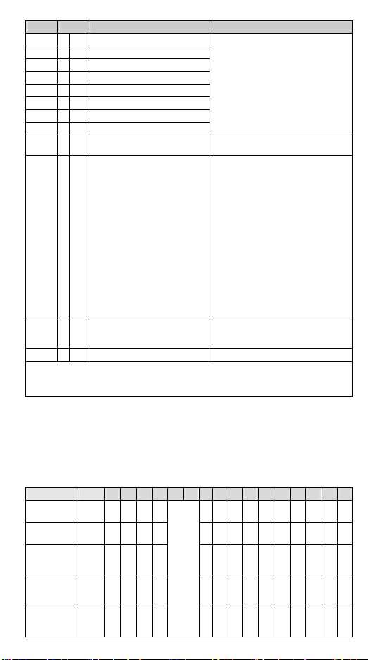
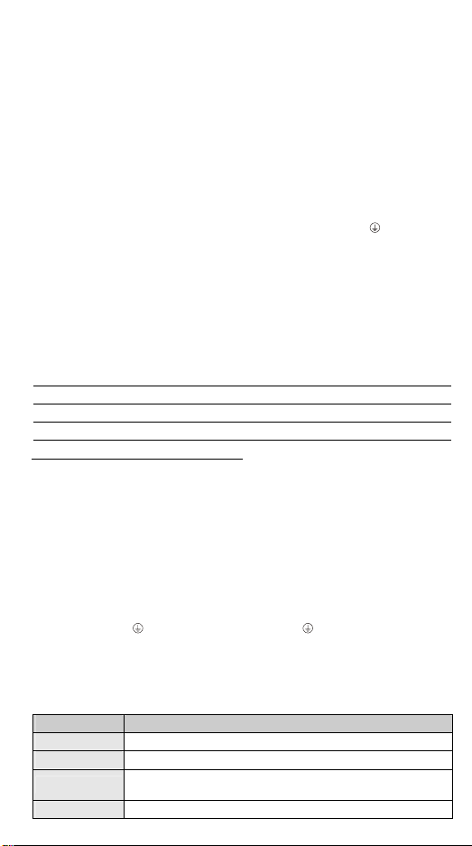
Product Profile & Dimension
Unit: mm [inch] [Figure 1]
1. DIN rail (35mm) 6. Terminals
2. Connection port for extension module 7. Mounting hole
3. Model name 8. I/O terminals
4. POWER, ERROR, A/D indicator 9. Mounting port for extension module
5. DIN rail clip
I/O Terminal Layout
24V
L+
0V
SLD
L+L+
Ch3Ch2Ch1
- 1 -
L+L+L+L+
L+
L -L -L -L -L -L -L -
L -
Ch7Ch6Ch5Ch4
Ch8
Page 3

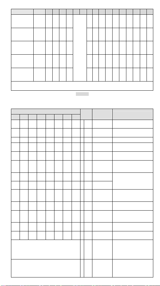
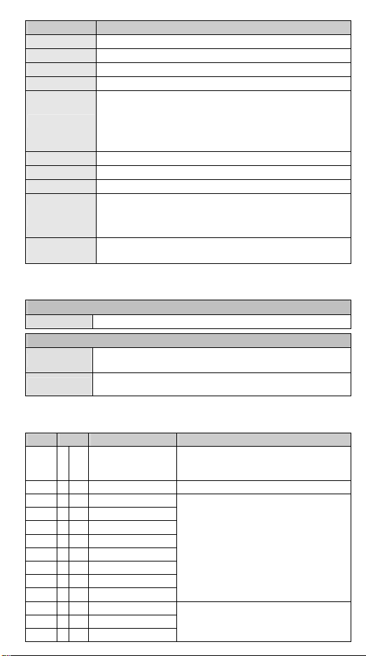
External Wiring
Thermocouple
Thermocouple
Ter mina l of
power module
*1: The wiring used for analog input should adopt the connection cable or shielding cable of
thermocouple temperature sensor J-type / K-type / R-type / S-type / T-type / E-type / N-type
and should be separated from other power cable or wirings that may cause interference.
The screw torque of the terminal should be 1.95 kg-cm (1.7 in-lbs).
*2: Please connect the
earth point and ground the system contact or connect it to the cover of power distribution
cabinet.
Note: DO NOT wire empty terminal. Use 60/75°C copper conductor only.
Shield ed
cable *1
Shielded
cable *1
System
grounding
CH1
CH8
SLD
SLD
24+
0V
L+
L -
L+
L -
DC/ DC
Converter
AGND
AGND
Cold-J uncti on
Compensation
A+5V
AG
+
-
+
-
*2
Class3 grounding
(100 or less)
[Figure 2]
terminal on both the power module and DVP08TC-H2 to the system
ADC
Specifications
Temperature
measurement module
Power supply voltage 24VDC (20.4VDC ~ 28.8VDC) (-15% ~ +20%)
Analog output channel 8 channels/module
Applicable sensor types
J-type, K-type, R-type, S-type, T-type, E-type, N-type Floating
thermocouple sensor, 0~150mV, ±150mV voltage input.
Range of input temp. See the table in section Temperature / Digital Curve
Range of digital
conversion
See the table in section Temperature / Digital Curve
Resolution 24 bits (0.1°C/0.1°F)
Overall accuracy ±0.6% when in full scale within the range of 0 ~ 55°C, 32 ~ 131°F
Response time 200ms × the number of channels
Isolation between digital circuits and analog circuits. Isolation
between channels.
Isolation
500VDC between digital circuits and Ground
500VDC between analog circuits and Ground
500VDC between analog circuits and digital circuits
500VDC between 24VDC and Ground
Digital data format 15 significant bits out of 16 bits are available; in 2’s complement
Average function Yes; available for setting up in CR#10 ~ CR#17; range: K1 ~ K100
Self-diagnosis Upper and lower bound detection/channel
ASCII/RTU mode. Communication speed: 9,600 / 19,200 / 38,400 /
Communication mode
(RS-485)
When connected to
DVP-PLC MPU in series
57,600 / 115,200 bps. ASCII data format: 7-bit, even bit, 1 stop bit
(7, E, 1). RTU data format: 8-bit, even bit, 1 stop bit (8, E, 1).
RS-485 cannot be used when connected to PLC MPU.
The modules are numbered from 0 to 7 automatically by their
distance from MPU. No. 0 is the closest to MPU and No. 7 is the
furthest. Maximum 8 modules are allowed to connect to MPU and
will not occupy any digital I/O points.
Explanation
- 2 -
Page 4

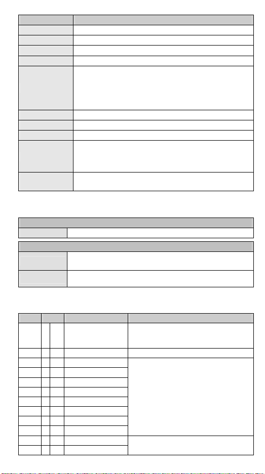
Other Specifications
Max. rated power
consumption
Operation/storage
Vibration/shock
immunity
24VDC (20.4VDC ~ 28.8VDC) (-15% ~ +20%), 2.5W supplied by
external power.
1. Operation: -10°C~ 60°C (Temperature), 50 ~ 95% (Humidity),
pollution degree 2
2. Storage: -25°C~ 70°C (Temperature), 5 ~ 95%(Humidity)
Standard: IEC61131-2, IEC 68-2-6 (TEST Fc)/IEC61131-2 & IEC
68-2-27 (TEST Ea)
Power supply
Environment
Control Register
CR# Attrib. Register name Explanation
#0 O R Model name
#1 O R Firmware version
#2 O R/W CH1 thermocouple type
#3 O R/W CH2 thermocouple type
#4 O R/W CH3 thermocouple type
#5 O R/W CH4 thermocouple type
#6 O R/W CH5 thermocouple type
#7 O R/W CH6 thermocouple type
#8 O R/W CH7 thermocouple type
#9 O R/W CH8 thermocouple type
#10 O R/W CH1 average time
#11 O R/W CH2 average time
#12 O R/W CH3 average time
#13 O R/W CH4 average time
#14 O R/W CH5 average time
#15 O R/W CH6 average time
#16 O R/W CH7 average time
#17 O R/W CH8 average time
#18 O R/W Temperature unit
#19 X R Average temp. measured at CH1
#20 X R Average temp. measured at CH2
#21 X R Average temp. measured at CH3
#22 X R Average temp. measured at CH4
#23 X R Average temp. measured at CH5
#24 X R Average temp. measured at CH6
#25 X R Average temp. measured at CH7
#26 X R Average temp. measured at CH8
Set up by the system.
DVP08TC-H2 model code = H’6804
User can read the model name from the
program and see if the extension
module exists.
Displaying the current firmware version
in hex; e.g. version 1.01 is indicated as
H’0101
The working mode of the channels in
the sensors selected by the
temperature measurement module. 10
working modes are available(J-type,
K-type, R-type, S-type, T-type, E-type,
N-type, 0~150mV, ±150mV, Unused).
Mode 0: J-type. Mode 1: K-type.
Mode 2: R-type. Mode 3: S-type.
Mode 4: T-type. Mode 5: E-type.
Mode 6: N-type. Mode 7: 0~150mV.
Mode 8: ±150mV. Mode -1: Unused.
Default value: H’0000。
Range of settings in CH1 ~ CH4:
K1 ~ K100. Default =K10.
K0 = centigrade, K1 = Fahrenheit.
Default =K0
Average temperature measured at
CH1~CH8.
The average temperature measured at
CH1~CH8 obtained from the average
time settings in CR#10 ~ CR#17.
- 3 -
Page 5
CR# Attrib. Register name Explanation
#27 O R/W OFFSET value of CH1
#28 O R/W OFFSET value of CH2
#29 O R/W OFFSET value of CH3
#30 O R/W OFFSET value of CH4
#31 O R/W OFFSET value of CH5
#32 O R/W OFFSET value of CH6
#33 O R/W OFFSET value of CH7
Adjustable OFFSET settings at CH1 ~
CH8
Range: -1,000 ~ +1,000
Default = K0
Unit: 0.1°C
Definition of OFFSET value: Module
measurement value – OFFSET value =
actual display value
#34 O R/W OFFSET value of CH8
#35 O R/W Communication address setting
#36 O R/W
Communication speed (baud
rate) setting
#37 X R Error status
#38~47 X R Reserved
Symbols: O: Latched. X: Non-latched.
R: Able to read data by FROM instruction or RS-485 communication.
W: Able to write data by TO instruction or RS-485 communication.
※ The corresponding parameter address H’4200 ~ H’4232 are for users to read/write
data by RS-485 communication. When using RS-485, the user has to separate the
module with MPU first.
Function: H’03 (read register data); H’06 (write 1 word datum into register); H’10
1.
(write many word data into register).
Latched CR should be written by RS-485 communication to stay latched. CR will
2.
not be latched if written by MPU through TO/DTO instruction.
Error status (see the table below)
CR#37:
Error status Value
Abnormal
power supply
Abnormal
module
Abnormal
digital range
of Ch1
Abnormal
digital range
of Ch2
Abnormal
digital range
of Ch3
b15 b14 b13 b12 b11 b10 b9 b8 b7 b6 b5 b4 b3 b2 b1 b0
K1
0 0 0 0 0 0 0 0 0 0 0 0 0 1
(H’1)
K2
0 0 0 0 0 0 0 0 0 0 0 0 1 0
(H’2)
K4
0 0 0 0 0 0 0 0 0 0 0 1 0 0
(H’4)
K8
0 0 0 0 0 0 0 0 0 0 1 0 0 0
(H’8)
K16
00 00
(H’10)
Reserved
For setting RS-485 communication
address. Range: 01 ~ 254, Default = K1.
For setting up communication speed:
9,600/19,200/ 38,400/57,600/115,200
bps. ASCII data format: 7-bit, even bit,
1 stop bit (7, E, 1). RTU data format:
8-bit, even bit, 1 stop bit (8, E, 1).
Default: H’0002.
b0: reserved
b1: 9,600 bps (default).
b2: 19,200 bps.
b3: 38,400 bps.
b4: 57,600 bps.
b5: 115,200 bps.
b14: High/low bit exchange of CRC
checksum (only valid in RTU
mode)
b15: Switch between ASCII/RTU
modes; 0 = ASCII mode (default)
Register for storing all error status. See
the table of error status for more
information.
-
0 0 0 0 0 1 0 0 0 0
- 4 -
Page 6
Error status Va lue
Abnormal
digital range
of Ch4
Abnormal
digital range
of Ch5
Abnormal
digital range
of Ch6
Abnormal
digital range
of Ch7
Abnormal
digital range
of Ch8
Note: Each error status is determined by the corresponding bit (b0 ~ b11) and there may be
more than 2 errors occurring at the same time. 0 = normal; 1 = error.
b15 b14 b13 b12 b11 b10 b9 b8 b7 b6 b5 b4 b3 b2 b1 b0
K32
0 0 0 0 0 0 0 0 1 0 0 0 0 0
(H’20)
K64
0 0 0 0 0 0 0 1 0 0 0 0 0 0
(H’40)
K128
0 0 0 0 0 0 1 0 0 0 0 0 0 0
(H’80)
K256
0 0 0 0 0 1 0 0 0 0 0 0 0 0
(H’100)
K512
0 0 0 0 1 0 0 0 0 0 0 0 0 0
(H’200)
[Table 1]
Adjust D/A Conversion Curve
CH1 CH2 CH3 Ch4 Ch5 Ch6 Ch7 Ch8
CR#
#100 #115 #130 #145 #160 #175 #190 #205 O R/W
#101 #116 #131 #146 #161 #176 #191 #206 O R/W
#102 #117 #132 #147 #162 #177 #192 #207 O R/W KP Default = K121.
#103 #118 #133 #148 #163 #178 #193 #208 O R/W KI
#104 #119 #134 #149 #164 #179 #194 #209 O R/W KD
#105 #120 #135 #150 #165 #180 #195 #210 O R/W
#106 #121 #136 #151 #166 #181 #196 #211 X R
#107 #122 #137 #152 #167 #182 #197 #212 X R
#108 #123 #138 #153 #168 #183 #198 #213 O R/W
#109 #124 #139 #154 #169 #184 #199 #214 O R/W
#110 #125 #140 #155 #170 #185 #200 #215 O R/W
#111 #126 #141 #156 #171 #186 #201 #216 X R
#112 #127 #142 #157 #172 #187 #202 #217 X R
#220 X R/W
#221 X R/W
Latched
- 5 -
Register
content
Temperature
SV
Sampling
time (s)
Default I
value
limit of I value
(Low word)
limit of I value
(High word)
Preheating
temperature
setting
Preheating
output setting
Output
percentage
(%)
Output width
(ms)
Output cycle
(ms)
Temperature
control
_Run/Stop
PID
Auto Tune
Explanation
Default = K0.
Range: K1 ~ K30 (s).
Default = K2.
Integral constant, Default =
K2,098.
Derivative constant, Default
= K-29.
Range: K-32768 ~ K32767.
Default = K0. Only valid
when PID Stop->Run.
Current accumulated offset
value. Default = K0.
Range: K-32768 ~ K32767.
Default = K0.
Range: K0 ~ K1,000 (unit:
0.1%). Default= K500.
Range: K0 ~ K1,000 (Unit:
0.1%). Default = K0.
Width of control output,
Default = K0.
Cycle of control output,
Default = K0.
b0: Ch1
b3: Ch4
b4: Ch5
b5: Ch6
b3: Ch4
b4: Ch5
b5: Ch6
b6: Ch7
b7: Ch8
b6: Ch7
b7: Ch8
b1: Ch2
b2: Ch3
0: Stop, 1: Run, Default = K0
b0: Ch1
b1: Ch2
b2: Ch3
0: Disabled, 1: Auto-tuning
Default = K0
Page 7
CH1 CH2 CH3 Ch4 Ch5 Ch6 Ch7 Ch8
CR#
#222 X R/W
#223 X R/W
Latched
Register
content
Heating/cooli
ng control
Preheating
function
The CR# listed above do not support RS※ -485 read/write。
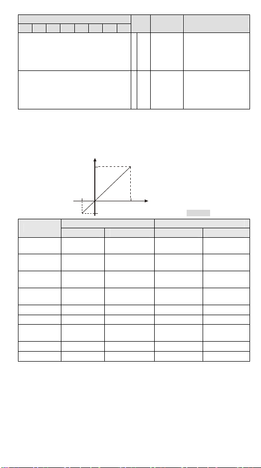
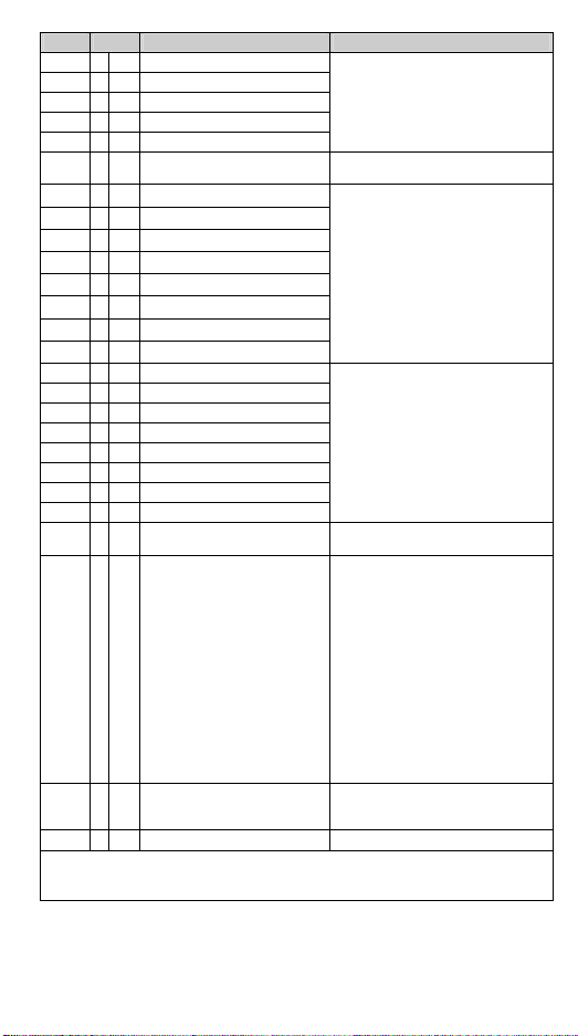
Temperature / Digital Curve
°C/°F Temperature Measurement Mode:
Digital Output
Max.
Explanation
b0: Ch1
b3: Ch4
b1: Ch2
b4: Ch5
b2: Ch3
b5: Ch6
0: Heater, 1: Cooler
Default = K0
b1: Ch2
b4: Ch5
b2: Ch3
b5: Ch6
b3: Ch4
b6: Ch7
0: Disable, 1: Enable
Default = K0
b6: Ch7
b7: Ch8
b7: Ch8
Min.
Min.
Thermo-couple
Range of input temperature Range of digital conversion
Min. (°C / °F) Max. (°C / °F) Min. (°C / °F) Max. (°C / °F)
J type -100°C / -148°F 1,150°C / 2,102°F K-1,000 / K-1,480
K type -100°C / -148°F 1,350°C / 2,462°F K-1,000 / K-1,480
R type 0°C / 32°F 1,750°C / 3,182°F K0 / K320
S type 0°C / 32°F 1,750°C / 3,182°F K0 / K320
Max.
Measured
temperature input
[Figure 3]
K11,500 /
K21,020
K13,500 /
K24,620
K17,500 /
K31,820
K17,500 /
K 31,820
T type -150°C / -238°F 390°C / 734°F K-1,500 / K-2,380 K3,900 / K7,340
E type -150°C / -238°F 980°C / 1,796°F K-1,500 / K-2,380 K9,800 / K17,960
N type -150°C / -238°F 1,280 °C / 2,336°F K-1,500 / K-2,380
K12,800 /
K23,360
0 ~ 150mV 0mV 150mV H0 HFFFF
±150mV -150mV 150mV K-30000 K30000
- 6 -
Page 8

………………………………………………………………… 繁體中文 ………………………………………………………………………
DVP08TC-H2 溫度量測模組可接受外部8 點 0~150mV電壓輸入(熱電耦溫度感測器 J, K,
R, S, T, E, N 型),將之轉換成 24 位元之數位信號。透過 DVP-PLC EH2 主機程式以指令
FROM/TO 來讀寫模組內之資料,模組內具有49 個 CR (Control Register) 暫存器,每個
暫存器有 16 bits。使用者可選擇攝氏溫度或華氏溫度,攝氏溫度輸入解析度為 0.1°C,華
氏溫度輸入解析度為 0.1°F。
a 本使用說明書僅提供電氣規格、功能規格、安裝配線部份說明,其它詳細之程式設計
及指令說明請見 DVP-PLC 應用技術手冊【程式篇】,選購之週邊裝置詳細說明請見該
產品隨機手冊或 DVP-PLC 應用技術手冊【特殊模組篇】。
a 本機為開放型 (OPEN TYPE) 機殼,因此使用者使用本機時,必須將之安裝於具防
塵、防潮及免於電擊/衝擊意外之外殼配線箱內。另必須具備保護措施(如:特殊之工
具或鑰匙才可打開)防止非維護人員操作或意外衝擊本體,造成危險及損壞。
a 交流輸入電源不可連接於輸入/出信號端,否則可能造成嚴重損壞,請在上電之前再
次確認電源配線。請勿在上電時觸摸任何端子。本體上之接地端子 務必正確的接
地,可提高產品抗雜訊能力。
a 由測溫體到溫調本體的配線路請用最短距離配線,為了避免雜訊及誘導的影響儘可能
將電源線和負載配線分開。
a 感測器熱電耦型式設定 CR#2~CR#9,如設定錯誤會造成量測重大誤差。
產品外觀尺寸與部位介紹
詳細圖示請參閱英文版頁碼 1 之 Figure1,單位:mm [inch]。
1. DIN 軌槽 (35mm) 6. 端子
2. 擴充模組連接口 7. 固定孔
3. 機種名稱 8. 端子配置
4. 電源、錯誤及轉換指示燈 9. 擴充模組連接座
5. DIN 軌固定扣
輸入⁄輸出端子台配置
請參閱英文版頁碼 1 之端子配置圖,在此語言版本省略說明。
外部配線
詳細圖示請參閱英文版頁碼 2 之 Figure 2,在此語言版本省略說明。
註 1:使用於類比輸入的配線應採用J / K / R / S / T / E / N 型熱電耦溫度感測器之連接線或隔離
線且應與其他電源線或可能引起雜訊之接線分開。端子螺絲扭力為 1.95 kg-cm (1.7 in-lbs)。
註 2:請將電源模組之
接點作第三種接地或接到配電箱之機殼上。
注意:空端子請勿配線。只能使用60/75°C 的銅導線。
端及 DVP08TC-H2 溫度量測模組之 端連接到系統接地點,再將系統
電氣規格
溫度量測模組 規格說明
電源電壓
類比訊號輸出通道 8通道/台
適合感應器形式
輸入溫度範圍 請參閱溫度⁄數位特性曲線附表
24VDC (20.4VDC ~ 28.8VDC) (-15% ~ +20%)
J-type, K-type, R-type, S-type, T-type, E-type, N-type 熱電耦感測器,
0~150mV, ±150mV 電壓輸入
- 7 -
Page 9
溫度量測模組 規格說明
數位轉換範圍 請參閱溫度⁄數位特性曲線附表
解析度
總和精密度
響應時間 200ms × 通道數
隔離方式
數位資料格式 16 位元二補數,有效位 15 bits。
平均功能 有(CR#10 ~ CR#17 可設定,範圍 K1 ~ K100)
自我診斷功能 上下極限偵測/通道
通訊模式 (RS-485)
與 DVP-PLC 主機
串接說明
24 bits (0.1°C/0.1°F)
±0.6% 在 (0 ~ 55°C, 32 ~ 131°F) 範圍內滿刻度時
類比電路與數位電路之間隔離,通道間隔離
數位電路與接地之間:500VDC
類比電路與接地之間:500VDC
類比電路與數位電路之間:500VDC
24VDC 與接地之間:500VDC
包含 ASCII/RTU 模式,通訊速率可選 (9,600 / 19,200 / 38,400 / 57,600 /
115,200),ASCII 模式資料格式固定為 7- bit、偶位元、1 stop bit (7, E, 1),
RTU 模式資料格式固定為 8-bit、偶位元、1 stop bit (8, E, 1)。當與 PLC
主機串接時,RS-485 通訊無法使用。
模組編號以靠近主機之順序自動編號由 0 到 7,最大可連接8 台且不佔用
數位 I/O 點數
其他規格
電源規格
額定最大消耗功率 直流24VDC (20.4VDC ~ 28.8VDC) (-15% ~ +20%), 2.5W, 由外部電源供應
操作⁄儲存環境
耐振動⁄衝擊
1. 操作:-10°C ~ 60°C(溫度),50 ~ 95%(濕度),污染等級 2
2. 儲存:-25°C ~ 70°C(溫度),5 ~ 95%(濕度)
國際標準規範 IEC61131-2, IEC 68-2-6 (TEST Fc)/IEC61131-2 & IEC
68-2-27 (TEST Ea)
環境規格
控制暫存器 CR
保持型 暫存器名稱 說明
CR#
#0 O R
#1 O R
#2 O R/W
#3 O R/W
#4 O R/W
#5 O R/W
#6 O R/W
#7 O R/W
#8 O R/W
#9 O R/W
#10 O R/W
#11 O R/W
機種型號
韌體版本 16 進制,顯示目前韌體版本,如 1.01 則 H’0101
CH1 熱電耦型式
CH2 熱電耦型式
CH3 熱電耦型式
CH4 熱電耦型式
CH5 熱電耦型式
CH6 熱電耦型式
CH7 熱電耦型式
CH8 熱電耦型式
CH1 平均次數
CH2 平均次數
系統內定,DVP08TC-H2 機種編碼 = H’6804
使用者可在程式中將此機種型號讀出,以判斷擴充
模組是否存在。
內容值用來設定溫度量測模組選擇感應器內部通
道的工作模式,共有 10 種模式(J-type, K-type,
R-type, S-type, T-type, E-type, N-type, 0~150mV,
±150mV, Unused)。
模式 0:J-type。模式 1:K-type。
模式 2:R-type。模式 3:S-type。
模式 4:T-ty pe。模式 5:E-type。
模式 6:N-type。模式 7:0~150mV。
模式 8:±150mV。模式-1:Unused。
出廠設定值為 H’0000。
通道 CH1 ~ CH8 訊號的平均次數設定,可設定範
圍 K1 ~ K100。
- 8 -
Page 10

保持型 暫存器名稱 說明
CR#
#12 O R/W
#13 O R/W
#14 O R/W
#15 O R/W
#16 O R/W
#17 O R/W
#18 O R/W
#19 X R
#20 X R
#21 X R
#22 X R
#23 X R
#24 X R
#25 X R
#26 X R
#27 O R/W
#28 O R/W
#29 O R/W
#30 O R/W
#31 O R/W
#32 O R/W
#33 O R/W
#34 O R/W
#35 O R/W
CH3 平均次數
CH4 平均次數
CH5 平均次數
CH6 平均次數
CH7 平均次數
CH8 平均次數
溫度單位設定 K0 = 攝氏,K1 = 華氏。出廠設定值為 K0
CH1 量測平均值
CH2 量測平均值
CH3 量測平均值
CH4 量測平均值
CH5 量測平均值
CH6 量測平均值
CH7 量測平均值
CH8 量測平均值
CH1 OFFSET 值
CH2 OFFSET 值
CH3 OFFSET 值
CH4 OFFSET 值
CH5 OFFSET 值
CH6 OFFSET 值
CH7 OFFSET 值
CH8 OFFSET 值
通訊位址設定
出廠設定值為 K10。
通道 CH1 ~ CH8 量測平均值顯示。
內容值為通道CH1 ~ CH8 量測溫度信號以CR#10
~ CR#17 設定之平均次數所取得之平均值。
通道 CH1 ~ CH8 提供使用者自行調整的 OFFSET
可調範圍:-1,000 ~ +1,000
出廠設定值為 K0。
OFFSET 值定義:模組量測值- OFFSET 值 = 實
際顯示值。
設定 RS-485 通訊位址,設定範圍1 ~ 254。
出廠設定值為 K1。
設定通訊速率,共有 9,600/19,200 bps/38,400
bps/57,600 bps/115,200 bps 五種。ASCII 模式資
料格式固定為 7-bit、偶位元、1 stop bit (7, E, 1),
RTU 模式資料格式固定為 8-bit、偶 位元、1 stop bit
(8, E, 1)。出廠設定值為 H’0002。
b0:保留。
#36 O R/W
通訊速率設定
b1:9,600 bps(位元/秒)(出廠設定值)。
b2:19,200 bps(位元/秒)。
b3:38,400 bps(位元/秒)。
b4:57,600 bps(位元/秒)。
b5:115,200 bps(位元/秒)。
b14:CRC 檢查碼高低位交換(僅 RTU 模式有效)。
b15:ASCII/RTU 模式切換,0 為ASCII(出廠設
定值)。
#37 X R
#38~47 X R
錯誤狀態
保留 -
儲存所有錯誤狀態的資料暫存器,詳細內容請參照
錯誤信息表。
符號定義: O:停電保持型。 X:非停電保持型。
R:可使用 FROM 指令讀取資料,或利用 RS-485 通訊讀取資料。
W:可使用 TO 指令寫入資料,或利用 RS-485 通訊寫入資料。
※ CR#0 ~ CR#34:對應之參數位址 H’4200 ~ H’4232 可提供使用者利用 RS-485 通訊來讀寫資
料。由 RS-485 通訊時須先將模組與主機分離。
1. 功能碼 (Function):H’03 讀出暫存器資料。H’06 寫入一個word 資料至暫存器。H’10 寫入
多筆 word 資料至暫存器。
- 9 -
Page 11

2. 停電保持型的CR 須由 RS-485 通訊來寫入才有停電保持的功能,如果是由主機以 TO/DTO
指令寫入則不會有停電保持的功能。
CR#37:錯誤狀態值請參照錯誤狀態表(請參閱英文版頁碼4 及頁碼 5 的 Table 1)
PID 控制暫存器範圍
CH1 CH2 CH3 Ch4 Ch5 Ch6 Ch7 Ch8
CR#
#100 #115 #130 #145 #160 #175 #190 #205 O R/W
#101 #116 #131 #146 #161 #176 #191 #206 O R/W
#102 #117 #132 #147 #162 #177 #192 #207 O R/W KP
#103 #118 #133 #148 #163 #178 #193 #208 O R/W KI
#104 #119 #134 #149 #164 #179 #194 #209 O R/W KD
#105 #120 #135 #150 #165 #180 #195 #210 O R/W
#106 #121 #136 #151 #166 #181 #196 #211 X R
#107 #122 #137 #152 #167 #182 #197 #212 X R
#108 #123 #138 #153 #168 #183 #198 #213 O R/W
#109 #124 #139 #154 #169 #184 #199 #214 O R/W
#110 #125 #140 #155 #170 #185 #200 #215 O R/W
#111 #126 #141 #156 #171 #186 #201 #216 X R
#112 #127 #142 #157 #172 #187 #202 #217 X R
#220 X R/W
#221 X R/W
#222 X R/W
#223 X R/W
※CR#100~ CR#223 不支援 RS-485 通訊讀寫。
保持型 暫存器名稱 說明
溫度設定值 出廠值為 K0
取樣時間 (s)
積分量預設值
積分量
(Low word)
積分量
(High word)
預熱溫度設定
預熱輸出設定
輸出%
輸出寬度(ms) 控制輸出寬度。出廠值為 K0。
輸出周期(ms) 控制輸出周期。出廠值為 K0。
溫度控制
_Run/Stop
PID
Auto Tune
加熱器/
冷卻器
預熱功能
可設定範圍 K1 ~ K30。出廠
值為 K2。
出廠值為 K12 1
積分常數,出廠值為K2,098。
微分常數,出廠值為 K-29。
可設定範圍 K-3 2768 ~
K32767。出廠值為 K0。PID
Stop->Run 有效
目前累積的偏差量。出廠值為
K0。
可設定範圍 K-3 2768 ~
K32767。出廠值為 K0。
可設定範圍 K0 ~ K1,0 00(單
位:0.1%)。出廠值為K500。
可設定範圍 K0 ~ K1,0 00(單
位:0.1%)。出廠值為 K0。
b0: Ch1
b3: Ch4
b1: Ch2
b4: Ch5
b2: Ch3
b5: Ch6
0:Stop ,1:Run
出廠值為 K0
b0: Ch1
b3: Ch4
b1: Ch2
b4: Ch5
b2: Ch3
b5: Ch6
0:不動作,1:Auto-tuning。
出廠值為 K0
b0: Ch1
b3: Ch4
b1: Ch2
b4: Ch5
b2: Ch3
b5: Ch6
0:加熱器,1:冷卻器。
出廠值為 K0
b1: Ch2
b4: Ch5
b2: Ch3
b5: Ch6
b3: Ch4
b6: Ch7
0:Disable,1:Enable。
出廠值為 K0
b6: Ch7
b7: Ch8
b6: Ch7
b7: Ch8
b6: Ch7
b7: Ch8
b7: Ch8
溫度⁄數位特性曲線
請參閱英文版頁碼 6 之說明。
- 10 -
Page 12
………………………………………………………………… 简体中文 ………………………………………………………………………
DVP08TC-H2 温度测量模块可接受外部8 点 0~150mV电压输入(热电耦温度传感器 J, K,
R, S, T, E, N 型),将之转换成 24 位的数字信号。透过 DVP-PLC EH2 主机程序以指令
FROM/TO 来读写模块内的数据,模块内具有 49 个 CR (Control Register) 寄存器,每个
寄存器有 16 bits。使用者可选择摄氏温度或华氏温度,摄氏温度输入分辨率为 0.1°C,华
氏温度输入分辨率为 0.1°F。
a 本使用说明书仅提供电气规格、功能规格、安装配线部份说明,其它详细的程序设计
及指令说明请见 DVP-PLC 应用技术手册【程序篇】,选购之外围装置详细说明请见该
产品随机手册或 DVP-PLC 应用技术手册【特殊模块篇】。
a 本机为开放型 (OPEN TYPE) 机壳,因此使用者使用本机时,必须将之安装于具防尘、
防潮及免于电击/冲击意外的外壳配线箱内。另必须具备保护措施(如:特殊的工具或
钥匙才可打开)防止非维护人员操作或意外冲击本体,造成危险及损坏。
a 交流输入电源不可连接于输入/出信号端,否则可能造成严重损坏,请在上电之前再
次确认电源配线。请勿在上电时触摸任何端子。本体上的接地端子 务必正确的接
地,可提高产品抗噪声能力。
a 由测温体到温调本体的配线路请用最短距离配线,为了避免噪声及诱导的影响尽可能
将电源线和负载配线分开。
a 传感器热电耦型式设定,請檢查 CR#2~CR#9,如设定错误会造成测量重大误差。
產品外觀尺寸與部位介紹
详细图示请参阅英文版页码 1 的 Figure1,单位:mm [inch]。
1. DIN 轨槽 (35mm) 6. 端子
2. 扩充模块连接口 7. 固定孔
3. 机种名称 8. 端子配置
4. 电源、错误及转换指示灯 9. 扩充模块连接座
5. DIN 轨固定扣
輸入⁄輸出端子台配置
详细图示请参阅英文版页码 1 的端子配置图,在此语言版本省略说明。
外部配線
详细图示请参阅英文版页码 2 的 Figure2,在此语言版本省略说明。
注 1:使用于模拟输入的配线应采用 J / K / R / S / T / E / N 型热电耦温度传感器的连接线或隔离
线且应与其它电源线或可能引起噪声的接线分开。端子螺丝扭力为 1.95 kg-cm (1.7 in-lbs)。
注 2:请将电源模块的
接点作第三种接地或接到配电箱的机壳上。
注意:空端子请勿配线。只能使用 60/75°C 的铜导线。
端及 DVP08TC-H2 温度测量模块的 端连接到系统接地点,再将系统
電氣規格
温度测量模块 规格说明
电源电压
模拟讯号输出信道 8通道/台
适合感应器形式
输入温度范围 请参阅温度⁄数字特性曲线附表
24VDC (20.4VDC ~ 28.8VDC) (-15% ~ +20%)
J-type, K-type, R-type, S-type, T-type, E-type, N-type 热电耦传感器,
0~150mV, ±150mV 电压输入
- 11 -
Page 13
温度测量模块 规格说明
数字转换范围 请参阅温度⁄数字特性曲线附表
分辨率
总和精密度 ±0.6% 在 (0 ~ 55°C, 32 ~ 131°F) 范围内满刻度时
响应时间 200ms × 通道数
隔离方式
数字数据格式 16 位二补码,有效位 15 bits。
平均功能 有(CR#10 ~ CR#17 可设定,范围 K1 ~ K100)
自我诊断功能 上下极限侦测/通道
通讯模式
(RS-485)
与 DVP-PLC 主机
串接说明
24 bits (0.1°C/0.1°F)
模拟电路与数字电路之间隔离,信道间隔离
数字电路与接地之间:500VDC
模拟电路与接地之间:500VDC
模拟电路与数字电路之间:500VDC
24VDC 与接地之间:500VDC
包含 ASCII/RTU 模式,通讯速率可选 (9,600 / 19,200 / 38,400 / 57,600 /
115,200),ASCII 模式数据格式固定为 7-bit、偶位、1 stop bit (7, E, 1),
RTU 模式数据格式固定为 8-bit、偶位 、1 stop bit (8, E, 1)。当 与 PLC 主机
串接时,RS-485 通讯无法使用。
模块编号以靠近主机的顺序自动编号由 0 到 7,最大可连接 8 台且不占用
数字 I/O 点数。
其他規格
电源规格
额定最大消耗功率 直流 24VDC (20.4VDC ~ 28.8VDC) (-15% ~ +20%), 2.5W, 由外部电源供应
操作⁄储存环境
耐振动⁄冲击
1. 操作:-10°C ~ 60°C(温度),50 ~ 95%(湿度),污染等级 2
2. 储存:-25°C ~ 70°C(温度),5 ~ 95%(湿度)
国际标准规范 IEC61131-2, IEC 68-2-6 (TEST Fc)/IEC61131-2 & IEC
68-2-27 (TEST Ea)
环境规格
控制寄存器 CR
保持型 寄存器名称 说明
CR#
#0 O R
#1 O R
#2 O R/W
#3 O R/W
#4 O R/W
#5 O R/W
#6 O R/W
#7 O R/W
#8 O R/W
#9 O R/W
#10 O R/W
#11 O R/W
#12 O R/W
机种型号
韧体版本 16 进制,显示目前韧体版本,如 1.01 则 H’0101
CH1 热电耦型式
CH2 热电耦型式
CH3 热电耦型式
CH4 热电耦型式
CH5 热电耦型式
CH6 热电耦型式
CH7 热电耦型式
CH8 热电耦型式
CH1 平均次数
CH2 平均次数
CH3 平均次数
系统内定,DVP08TC-H2 机种编码 = H’6804
使用者可在程序中将此机种型号读出,以判断扩充
模块是否存在。
内容值用来设定温度测量模块选择感应器内部信
道的工作模式,共有 10 种模式(J-type, K-type,
R-type, S-type, T-type, E-type, N-type, 0~150mV,
±150mV, Unused)。
模式 0:J-type。模式 1:K-type。
模式 2:R-type。模式 3:S-type。
模式 4:T-ty pe。模式 5:E-type。
模式 6:N-type。模式 7:0~150mV。
模式 8:±150mV。模式-1:Unused。
出厂设定值为 H’0000。
信道 CH1 ~ CH4 讯号的平均次数设定,可设定范
围 K1 ~ K100。
出厂设定值为 K10。
- 12 -
Page 14

保持型 寄存器名称 说明
CR#
#13 O R/W
#14 O R/W
#15 O R/W
#16 O R/W
#17 O R/W
#18 O R/W
#19 X R
#20 X R
#21 X R
#22 X R
#23 X R
#24 X R
#25 X R
#26 X R
#27 O R/W
#28 O R/W
#29 O R/W
#30 O R/W
#31 O R/W
#32 O R/W
#33 O R/W
#34 O R/W
#35 O R/W
CH4 平均次数
CH5 平均次数
CH6 平均次数
CH7 平均次数
CH8 平均次数
温度单位设定 K0 = 摄氏,K1 = 华氏。出厂设定值为 K0
CH1 测量平均值
CH2 测量平均值
CH3 测量平均值
CH4 测量平均值
CH5 测量平均值
CH6 测量平均值
信道 CH1 ~ CH8 测量平均值显示。
内容值为通道 CH1 ~ CH8 测量温度信号以 CR#10
~ CR#17 设定的平均次数所取得的平均值。
CH7 测量平均值
CH8 测量平均值
CH1 OFFSET 值
CH2 OFFSET 值
CH3 OFFSET 值
CH4 OFFSET 值
CH5 OFFSET 值
CH6 OFFSET 值
通道 CH1 ~ CH4 提供使用者自行调整的 OFFSET
可调范围:-1,000 ~ +1,000
出厂设定值为 K0。
OFFSET 值定义:模块测量值- OFFSET 值 = 实
际显示值。
CH7 OFFSET 值
CH8 OFFSET 值
通讯地址设定
设定 RS-485 通讯地址,设定范围 1 ~ 254。
出厂设定值为 K1。
设定通讯速率,共有 9,600/19,200 bps/38,400
bps/57,600 bps/115,200 bps 五种。ASCII 模式数
据格式固定为 7-bit、偶位、1 stop bit (7, E, 1),RTU
模式数据格式固定为 8-bit、偶位、1 stop bit (8, E,
1)。出厂设定值为 H’0002。
b0:保留。
#36 O R/W
通讯速率设定
b1:9,600 bps(位/秒)(出厂设定值)。
b2:19,200 bps(位/秒)。
b3:38,400 bps(位/秒)。
b4:57,600 bps(位/秒)。
b5:115,200 bps(位/秒)。
b14:CRC 检查码高低位交换(仅 RTU 模式有效)。
b15:ASCII/RTU 模式切换,0 为 ASCII(出厂设
定值)。
#37 X R
#38~47 X R
错误状态
保留 -
储存所有错误状态的数据寄存器,详细内容请参照
错误信息表。
符号定义: O:停电保持型。 X:非停电保持型。
R:可使用 FROM 指令读取数据,或利用 RS-485 通讯读取数据。
W:可使用 TO 指令写入数据,或利用 RS-485 通讯写入数据。
CR#0 ~ CR#34※ :对应的参数地址 H’4200 ~ H’4232 可提供使用者利用 RS-485 通讯来读写数
据。由 RS-485 通讯时须先将模块与主机分离。
1. 功能码 (Function):H’03 读出寄存器数据。H’06 写入一个 word 数据至寄存器。H’10 写入
多笔 word 数据至寄存器。
- 13 -
Page 15

2. 停电保持型的 CR 须由 RS-485 通讯来写入才有停电保持的功能,如果是由主机以 TO/DTO
指令写入则不会有停电保持的功能。
CR#37:错误状态值请参照错误状态表(请参阅英文版頁碼4 及頁碼 5 的 Table 1)
PID 控制寄存器範圍
CH1 CH2 CH3 Ch4 Ch5 Ch6 Ch7 Ch8
CR#
#100 #115 #130 #145 #160 #175 #190 #205 O R/W
#101 #116 #131 #146 #161 #176 #191 #206 O R/W
#102 #117 #132 #147 #162 #177 #192 #207 O R/W KP
#103 #118 #133 #148 #163 #178 #193 #208 O R/W KI
#104 #119 #134 #149 #164 #179 #194 #209 O R/W KD
#105 #120 #135 #150 #165 #180 #195 #210 O R/W
#106 #121 #136 #151 #166 #181 #196 #211 X R
#107 #122 #137 #152 #167 #182 #197 #212 X R
#108 #123 #138 #153 #168 #183 #198 #213 O R/W
#109 #124 #139 #154 #169 #184 #199 #214 O R/W
#110 #125 #140 #155 #170 #185 #200 #215 O R/W
#111 #126 #141 #156 #171 #186 #201 #216 X R
#112 #127 #142 #157 #172 #187 #202 #217 X R
#220 X R/W
#221 X R/W
#222 X R/W
#223 X R/W
CR#100~ CR#223※ 不支持 RS-485 通讯读写。
保持型 寄存器名称 说明
温度设定值 出厂值为 K0
取样时间 (s)
积分量默认值
积分量
(Low word)
积分量
(High word)
预热温度设定
预热输出设定
输出%
输出宽度(ms) 控制输出宽度。出厂值为 K0。
输出周期(ms) 控制输出周期。出厂值为 K0。
温度控制
_Run/Stop
PID
Auto Tune
加热器/
冷却器
预热功能
可设定范围 K1 ~ K30。出厂
值为 K2。
出厂值为 K12 1
积分常数,出厂值为 K2,098。
微分常数,出厂值为 K-29。
可设定范围 K-3 2768 ~
K32767。出厂值为 K0。PID
Stop->Run 有效
目前累积的偏差量。出厂值为
K0。
可设定范围 K-3 2768 ~
K32767。出厂值为 K0。
可设定范围 K0 ~ K1,000(单
位:0.1%)。出 厂值为 K500。
可设定范围 K0 ~ K1,000(单
位:0.1%)。出厂值为 K0。
b0: Ch1
b3: Ch4
b1: Ch2
b4: Ch5
b2: Ch3
b5: Ch6
0:Stop ,1:Run
出厂值为 K0
b0: Ch1
b3: Ch4
b1: Ch2
b4: Ch5
b2: Ch3
b5: Ch6
0:不动作,1:Auto-tuning。
出厂值为 K0
b0: Ch1
b3: Ch4
b1: Ch2
b4: Ch5
b2: Ch3
b5: Ch6
0:加热器,1:冷却器。
出厂值为 K0
b1: Ch2
b4: Ch5
b2: Ch3
b5: Ch6
b3: Ch4
b6: Ch7
0:Disable,1:Enable。
出厂值为 K0
b6: Ch7
b7: Ch8
b6: Ch7
b7: Ch8
b6: Ch7
b7: Ch8
b7: Ch8
溫度⁄數位特性曲線
请参阅英文版页码 6 之说明。
- 14 -
Page 16

………………………………………………………………… TÜRKÇE …………………………………………………………………
DELTA DVP PLC Serisini seçtiğiniz için teşekkürler. DVP08TC-H2 ürünü 8 adet
0~150mV voltaj giriş termokupl sıcaklık sensör (J-tipi, K-tipi, R-tipi, S-tipi, T-tipi, E-tipi,
N-tipi) bilgisini alır ve bunları 24-bit dijital sinyallere dönüştürür. Ayrıca, DVP-EH2 MPU
programı içindeki FROM/TO komutları ile DVP08TC-H2 içindeki data okunabilir veya
yazılabilir. Ürün içinde 49 adet 16-bit kontrol register (CR) vardır. DVP08TC-H2 sıcaklığı
Selsius (çözünürlük: 0.1°C) ve Fahrenayt (çözünürlük: 0.1°F) olarak gösterir.
a Bu bilgi dökümanı sadece ürünün elektriksel özellikleri, genel özellikleri, kurulum ve
bağlantısı hakkında bilgiler sağlar. Programlama ve komutlar hakkında detaylı bilgi
için “DVP-PLC Application Manual: Programming” kitabına bakınız. Opsiyonel
donanımlar ile ilgili daha fazla bilgi için, ilgili ürünün bilgi dökümanını veya “DVP-PLC
Application Manual: Special I/O Modules”kitabını inceleyiniz.
a DVP08TC-H2 ürünü AÇIK-TİP bir ünite olup, kurulumu toz, rutubet, elektrik şoku ve
titreşimin olmadığı yerlere yapılmalıdır. Tehlikeleri ve ürünün zarar görmesini
önlemek için yetkili olmayan kişilerin ürüne müdahale etmesini önleyecek koruyucu
önlemler alınmalıdır. (Örneğin ürünün kurulduğu panoya kilit konulması gibi).
a Ürünün giriş/çıkış terminallerine AC besleme bağlamayınız, aksi halde PLC zarar
görebilir. Enerji vermeden önce tüm bağlantıları kontrol ediniz. Elektromanyetik
gürültüyü önlemek için, PLC’nin doğru topraklandığından emin olunuz . Enerji
varken ürün terminallerine dokunmayınız.
a Termokupl ve PLC arasındaki kabloyu mümkün olduğunca kısa tutunuz ve elektriksel
gürültüyü önlemek için güç kablolarını I/O kablolarından uzak muhafaza ediniz.
a Termokupl sıcaklık sensör modunu ayarladığınız zaman, lütfen CR#2~ CR#9
ayarlarının doğru olduğuna emin olunuz, aksi halde ciddi zarar meydana gelebilir.
Ürün Görünüşü & Ölçüler
Detaylı bilgi için için Sayfa 1’deki Şekil 1’e bakınız. Birim: mm [inch].
1. DIN ray (35mm) 6. Terminaller
2. İlave modül bağlantı portu 7. Montaj deliği
3. Model adı 8. I/O terminaller
4. POWER, ERROR, A/D indikator 9. İlave modül bağlantı portu
5. DIN ray klipsi
I/O Terminal Planı
Detaylı bilgi için Sayfa 1’de Terminal Layout şekline bakınız.
Harici Bağlantı
Detaylı bilgi için Sayfa 2’deki Şekil 2’ye bakınız.
*1: Analog giriş için kullanılan bağlantı J-tipi / K-tipi / R-tipi / S-tipi / T-tipi / E-tipi / N-tipi termokupl
sıcaklık sensörü ekranlı kablosu veya ona uyumlu bir kablo olmalı ve elektriksel gürültüyü
önlemek için bağlantısı diğer güç kablosu ve bağlantılarından uzak yapılmalıdır. Terminal
vidaları sıkma torku 1.95 kg-cm (1.7 in-lbs) olmalıdır.
*2:Güç modülü ve DVP08TC-H2
sonra panonun kasasına bağlatınız.
Not: BOŞ terminallere bağlantı yapmayınız. Sadece 60/75°C bakır iletken kullanınız.
terminalini lütfen sistem toprağına bağlayınız ve daha
Özellikler
Sıcaklık Ölçüm Modülü Açıklama
Besleme Voltajı 24VDC (20.4VDC ~ 28.8VDC) ( -15% ~ +20%)
Analog çıkış kanalı 8 kanal/modül
Uygulanabilen sensör
tipleri
Giriş sıcaklık aralığı Sıcaklık / Dijital Eğrisi tablosuna bakınız
Dijital dönüşüm aralığı Sıcaklık / Dijital Eğrisi tablosuna bakınız
Çözünürlük 24 bit (0.1°C/0.1°F)
J-tipi, K-tipi, R-tipi, S-tipi, T-tipi, E-tipi, N-tipi Floating termokupl sensor,
0~150mV, ±150mV voltaj giriş.
- 15 -
Page 17

Sıcaklık Ölçüm Modülü Açıklama
Tam doğruluk ±0.6% tam skala 0 ~ 55°C, 32 ~ 131°F sıcaklık ar alığında iken
Cevap zamanı 200m s × kanal sayısı
Izolasyon
Dijital data formatı 16 bit işaretli sayı formatındadır.
Ortalama fonksiyonu Evet; CR#10 ~ CR#17 içinde ayarlanabilir; ayar aralığı: K1 ~ K100
Self-teşhis Üst ve alt limit algılama/kanal
Haberleşme modu
(RS-485)
DVP-PLC MPU’ya
bağlanıldığı zaman
Dijital devreler ve analog devreler arası i zolasyon. Kanallar arası izolasyon.
500VDC dijital devreler ve Ground aras ı
500VDC analog devreler ve Ground arası
500VDC analog devreler ve dijital devrel er arası
500VDC 24VDC ve Ground arası
ASCII/RTU mod. Haberleşme hızı: 9,600 / 19,200 / 38,400 / 57, 600 /
115,200 bps. ASCII data formatı: 7-bit, even bit, 1 stop bit (7, E, 1). RTU
data formatı: 8-bit, even bit, 1 stop bit (8, E, 1). PLC MPU’ya bağlandığı
zaman RS-485 kullanılamaz.
MPU’dan uzaklığına gore 0 – 7 arası num aralandırılır. MPU’ya en yakın
modülün adresi 0 ve MPU’ya en uzak modülün adresi 7 olur. Maksimum 8
modül bağlanabilir ve modüller dij ital I/O işgal etmez.
Diğer Özellikler
Maksimum güç
tüketim oranı
Çalışma/saklama
Titreşim/şok
bağışıklığı
24VDC (20.4VDC ~ 28.8VDC) (-15% ~ +20%), 2.5W harici güç ile
beslenir.
1. Çalışma: -10°C~ 60°C (Sıcaklık), 50 ~ 95% (Rutubet), kirlenme
derecesi 2
2. Saklama: -25°C~ 70°C (Sıcaklık), 5 ~ 95%(Rutubet)
Standard: IEC61131-2, IEC 68-2-6 (TEST Fc)/IEC61131-2 & IEC
68-2-27 (TEST Ea)
Güç Kaynağı
Ortam Koşulları
Kontrol Register
CR# Özellik Register adı Açıklama
#0 O R Model adı
#1 O R Yazılım versiyonu
#2 O R/W CH1 Termokupl tipi
#3 O R/W CH2 Termokupl tipi
#4 O R/W CH3 Termokupl tipi
#5 O R/W CH4 Termokupl tipi
#6 O R/W CH5 Termokupl tipi
#7 O R/W CH6 Termokupl tipi
#8 O R/W CH7 Termokupl tipi
#9 O R/W CH8 Termokupl tipi
#10 O R/W CH1 ortalama adeti
#11 O R/W CH2 ortalama adeti
#12 O R/W CH3 ortalama adeti
Sistemden ayarlanır.
DVP08TC-H2 model kodu = H’6804
Kullanıcılar sistemden model ismini
okuyabilir ve modülünü doğruluğunu ve
mevcudiyetini anlayabilir.
Mevcut yazılım versiyonunu hex. olarak
gösterir. Örneğin versiyon 1.01 değeri
H’0101 olarak gösterilir.
Kanalların çalışma modu sensor seçimi
sıcaklık ölçüm modülü ile seçilir. 10
çalışma modu vardır. (J-tipi, K-tipi,
R-tipi, S-tipi, T-tipi, E-tipi, N-tipi,
0~150mV, ±150mV kullanılmaz).
Mod 0: J-tipi. Mod 1: K-tipi.
Mod 2: R-tipi. Mod 3: S-tipi.
Mod 4: T-tipi. Mod 5: E-tipi.
Mod 6: N-tipi. Mod 7: 0~150mV.
Mod 8: ±150mV. Mod -1: Kullanılmaz.
Default değeri: H’0000。
CH1 ~ CH4 ayar aralığı: K1 ~ K100.
Default =K10.
- 16 -
Page 18
CR# Özellik Register adı Açıklama
#13 O R/W CH4 ortalama adeti
#14 O R/W CH5 ortalama adeti
#15 O R/W CH6 ortalama adeti
#16 O R/W CH7 ortalama adeti
#17 O R/W CH8 ortalama adeti
#18 O R/W Sıcaklık birimi
#19 X R CH1’de ölçülen Ortalama sıcaklık
#20 X R CH2’de ölçülen Ortalama sıcaklık
#21 X R CH3’de ölçülen Ortalama sıcaklık
#22 X R CH4’de ölçülen Ortalama sıcaklık
#23 X R CH5’de ölçülen Ortalama sıcaklık
#24 X R CH6’da ölçülen Ortalama sıcaklık
#25 X R CH7’de ölçülen Ortalama sıcaklık
#26 X R CH8’de ölçülen Ortalama sıcaklık
#27 O R/W CH1 OFFSET değeri
#28 O R/W CH2 OFFSET değeri
#29 O R/W CH3 OFFSET değeri
#30 O R/W CH4 OFFSET değeri
#31 O R/W CH5 OFFSET değeri
#32 O R/W CH6 OFFSET değeri
#33 O R/W CH7 OFFSET değeri
#34 O R/W CH8 OFFSET değeri
#35 O R/W Haberleşme adresi ayarı
#36 O R/W Haberleşme hızı (baud rate) ayarı
#37 X R Hata durumu
#38~47 X R Rezerve
Semboller: O: Kalıcı. X: Kalıcı değil.
R: FROM komutu veya RS-485 haberleşme ile okunabilen data.
※ Parametre adreslerine karşılık gelen H’4200 ~ H’4232 RS-485 adresleri, haberleşme
W: TO komutu veya RS-485 haberleşme ile yazılabilen data.
ile okuma/yazma için kullanılır. RS-485 kullanılcağı zaman ilk önce modül MPU’dan
ayrılmalıdır.
Fonksiyon: H’03 (register data okuma); H’06 (register içine 1 word yazma); H’10
1.
(register içine çoklu word yazma).
K0 = Santigrad, K1 = Fahrenayt.
Default =K0
CH1~CH8’de ölçülen ortalama sıcaklık.
CH1~CH8’de ölçülen ortalama sıcaklık
değeri CR#10 ~ CR#17 ‘deki ortalama
adedi ile elde edilir.
CH1 ~ CH8 Ayarlanabilir OFFSET ayarı
Ayar aralığı: -1,000 ~ +1,000
Default = K0
Birim: 0.1°C
OFFSET değeri açıklaması: Modül
ölçüm değeri – OFFSET değeri =
gerçek gösterge değeri
RS-485 haberleşme adresi ayarı. Ayar
Aralığı: 01 ~ 254, Default = K1.
Haberleşme hızı ayarı: 9,600/19,200/
38,400/57,600/115,200 bps. ASCII data
formatı: 7-bit, even bit, 1 stop bit (7, E,
1). RTU data format: 8-bit, even bit, 1
stop bit (8, E, 1). Default: H’0002.
b0: rezerve
b1: 9,600 bps (default).
b2: 19,200 bps.
b3: 38,400 bps.
b4: 57,600 bps.
b5: 115,200 bps.
b14: CRC checksum Yüksek/düşük bit
değişimi. (Sadece RTU modda)
b15: ASCII/RTU mod seçimi; 0 = ASCII
mode (default)
Tüm hata durumlarını kaydeden
register. Dafa fazla bilgi için hata
tablosuna bakınız.
-
- 17 -
Page 19

Kalıcı CR’nin Kalıcı olabilmesi için RS-485 ile yazılması gerekir. Eğer MPU
2.
üzerinden TO/DTO komutları ile yazılırsa CR’ler kalıcı olmaz.
CR#37: Hata durumu
Hata durumu Değer b15 b14 b13 b12 b11 b10 b9 b8 b7 b6 b5 b4 b3 b2 b1 b0
Anormal
besleme
Anormal modül
Ch1 Anormal
dijital aralık
Ch2 Anormal
dijital aralık
Ch3 Anormal
dijital aralık
Ch4 Anormal
dijital aralık
Ch5 Anormal
dijital aralık
Ch6 Anormal
dijital aralık
Ch7 Anormal
dijital aralık
Ch8 Anormal
dijital aralık
Not: Her bir hata durumu ona karşılık gelen bit ile belirlenir (b0 ~ b11) ve 2 veya daha fazla hata aynı
anda meydana gelebilir. 0 = normal; 1 = hata.
(aşağıdaki tabloya bakınız)
K1
0 0 0 0 0 0 0 0 0 0 0 0 0 1
(H’1)
K2
0 0 0 0 0 0 0 0 0 0 0 0 1 0
(H’2)
K4
0 0 0 0 0 0 0 0 0 0 0 1 0 0
(H’4)
K8
0 0 0 0 0 0 0 0 0 0 1 0 0 0
(H’8)
K16
0 0 0 0 0 0 0 0 0 1 0 0 0 0
(H’10)
K32
0 0 0 0 0 0 0 0 1 0 0 0 0 0
(H’20)
K64
0 0 0 0 0 0 0 1 0 0 0 0 0 0
(H’40)
K128
0 0 0 0 0 0 1 0 0 0 0 0 0 0
(H’80)
K256
0 0 0 0 0 1 0 0 0 0 0 0 0 0
(H’100)
K512
00 00
(H’200)
Rezerve
1 0 0 0 0 0 0 0 0 0
D/A Dönüşüm Eğrisi Ayarlama
CH1 CH2 CH3 Ch4 Ch5 Ch6 Ch7 Ch8
CR#
#100 #115 #130 #145 #160 #175 #190 #205 O R/W Sıcaklık SV Default = K0.
#101 #116 #131 #146 #161 #176 #191 #206 O R/W
#102 #117 #132 #147 #162 #177 #192 #207 O R/W KP Default = K121.
#103 #118 #133 #148 #163 #178 #193 #208 O R/W KI
#104 #119 #134 #149 #164 #179 #194 #209 O R/W KD Türev sabiti, Default = K-29.
#105 #120 #135 #150 #165 #180 #195 #210 O R/W
#106 #121 #136 #151 #166 #181 #196 #211 X R
#107 #122 #137 #152 #167 #182 #197 #212 X R
#108 #123 #138 #153 #168 #183 #198 #213 O R/W
#109 #124 #139 #154 #169 #184 #199 #214 O R/W
#110 #125 #140 #155 #170 #185 #200 #215 O R/W
#111 #126 #141 #156 #171 #186 #201 #216 X R
#112 #127 #142 #157 #172 #187 #202 #217 X R
#220 X R/W
Kalıcı
- 18 -
Register
içeriği
Örnekleme
zamanı (s)
Default I
değeri
I değeri limiti
(Düşük word)
I değeri limiti
(Yüksekword)
Önısıtma
sıcaklık
değeri
Önısıtma
çıkış değeri
Çıkış yüzdesi
(%)
Çıkış genişliği
(ms)
Çıkış saykıl
(ms)
Sıcaklık
kontrol
_Run/Stop
Açıklama
Aralık: K1 ~ K30 (s).
Default = K2.
Integral sabiti,
Default = K2,098.
Aralık: K-32768 ~ K32767.
Default = K0. Sadece PID
Stop->Run olunca geçerli.
Mevcut toplam offset değeri.
Default = K0.
Aralık: K-32768 ~ K32767.
Default = K0.
Aralık: K0 ~ K1,000 (birim:
0.1%). Default= K500.
Aralık: K0 ~ K1,000 (Birim:
0.1%). Default = K0.
Kontrol çıkışı genişliği,
Default = K0.
Kontrol çıkış saykılı,
Default = K0.
b0: Ch1
b3: Ch4
b4: Ch5
b5: Ch6
b6: Ch7
b7: Ch8
b1: Ch2
b2: Ch3
0: Stop, 1: Run, Default = K0
Page 20

CH1 CH2 CH3 Ch4 Ch5 Ch6 Ch7 Ch8
CR#
#221 X R/W
#222 X R/W
#223 X R/W
Kalıcı
Register
içeriği
PID
Auto Tune
Isıtma /
soğutma
kontrol
Önısıtma
fonksiyonu
Açıklama
b0: Ch1
b3: Ch4
b1: Ch2
b4: Ch5
b2: Ch3
b5: Ch6
0: Pasif, 1: Auto-tuning
Default = K0
b0: Ch1
b3: Ch4
b1: Ch2
b4: Ch5
b5: Ch6
b2: Ch3
0: Isıtma, 1: Soğutma
Default = K0
b4: Ch5
b1: Ch2
b2: Ch3
b5: Ch6
b3: Ch4
b6: Ch7
0: Pasif, 1: Aktif
Default = K0
※ Yukarıda listelenmiş CR# registerler RS-485 okuma/yazma desteklemez。
Sıcaklık / Dijital Eğrisi
°C/°F Sıcaklık Ölçüm Modu: Sayfa 6 içindeki Şekil 3 sıcaklık/dijital eğrisine bakınız.
b6: Ch7
b7: Ch8
b6: Ch7
b7: Ch8
b7: Ch8
- 19 -
 Loading...