

Page 1

2018-07-20
5014002905-6P05
Page 2

………………………………………………………………… ENGLISH …………………………………………………………………
Thank you for choosing Delta DVP series PLC. DVP04 /06PT-S is able to receive 4/6 points of RTDs and
convert them into 16-bit digital signals. Through F ROM/TO instructions in DVP Slim series MPU pr ogram,
the data can be read and written. There are many 16-bit control registers (CR) in modules. The power unit
is separate from it and is small in size and easy to install.
EN DVP04/06PT-S is an OPEN-TYPE device. It should be installed in a control cabinet free of airborne
dust, humidity, electric shock and vibration. To prevent non-maintenance staff from operating
DVP04/06PT-S, or to prevent an accident from dam aging DVP04/06PT-S, the control cabinet in
which DVP04/06PT-S is installed should be equipped with a safeguard. For example, the control
cabinet in which DVP04/06PT-S is installed can be un locked with a special tool or key.
EN DO NOT connect AC power to any of I/O terminals, other wise serious damage may occur. Please
check all wiring again before DVP04/06 PT-S is powered up. After DVP04/06PT-S is disconnected,
Do NOT touch any terminals in a minute. Make sure th at the ground terminal
on
DVP04/06PT-S is correctly grounded in order to prevent electromagnetic interfer ence.
FR DVP04/06PT-S est un module OUVERT. Il doit être installé que dans une enceinte protectrice
(boitier, armoire, etc.) saine, dépourvue de poussière , d’humidité, de vibrations et hors d’atteinte
des chocs électriques. La protection do it éviter que les personnes non habilitées à la maintenance
puissent accéder à l’appareil (par exem ple, une clé ou un outil doivent être nécess aire pour ouvrir
a protection).
FR Ne pas appliquer la tension secteur sur les bornes d’entrées/Sorties, ou l’appareil D VP04/06PT-S
pourra être endommagé. Merci de vérifier encore une fois le câblage avant la mise sous tension du
DVP04/06PT-S. Lors de la déconnection de l’appareil, ne pas toucher les connecteurs dans la
minute suivante. Vérifier que la ter re est bien reliée au connecteur de terre
afin d’éviter toute
interférence électromagnétique.
Product Profile & Dimension
1
L+
L-CH
1
I-
L+
L-CH
2
I-
L+
C
L-
H
3
2
3
I-
L+
C
H
L-
4
I-
L+
C
L-
H
5
I-
L+
C
L-
H
D VP- 06 PT
6
I-
60.00 3.40
5
4
3.0090.00
25.20
6
7
8
10
9
3
11
12
11
13
60.00
3.00
14
3.00
1. Status indicator (POWER,
RUN and ERROR)
4. I/O terminals 5. I/O point indicator 6. Mounting holes
7. Specification label 8. I/O module connection port 9. I/O module clip
10. DIN rail (35mm) 11. I/O module clip
13. Power connection port
(DVP04PT-S)
Unit: mm
2. Model name 3. DIN rail clip
12. RS-485 communication port
(DVP04PT-S)
14. I/O connection port
- 1 -
[ Figure 1 ]
Page 3

I/O Terminal Layout
,
DVP04PT-S
CH1 Ch2 Ch3 Ch4
DVP06PT
CH1
CH2
L-L+FGL-L+
FGI- L+FGI-L-L+ FGI-L-I-
L-L+L-L+
CH3 CH4 CH5 CH6
I- L+I-L-L+ I-L-I-
L-L+ I- L+ I-L-
[ Figure 2 ]
External Wiring
Pt1000
2-Wire
Shielded cable*1
Pt100
3-Wir e
Note1: Use only the wires that are packed with the temperature sensor for analog input and separate from
other power line or any wire that ma y cause noise.
Note2: 3-wire RTD sensor provides a compens ation loop that can be used to subtract the wire
resistance while 2-wire RTD sensor has no mechanism to compensate. Use cables
(3-wired) with the same length (less than 2 00 m) and wire resistance of less than 2 0
ohm.
Note3: If there is noise, please connect the shielded cables to the system earth point, and then ground the
system earth point or connect it to the distributio n box.
Note4: Please keep wires as short as possib le when connecting the module to a devic e whose
temperature is going to be measured, and keep the power cable used as far away from the cable
connected to a load as possible to prevent noise interference.
Note5: Please connect
ground, and then ground the system ground or connect the system ground to a distr ibution box.
Shielded cable* 1
on a power supply module and on the temperature module to a system
CH1
CH6
L+
L I -
AG
L+
L I-
AG
Electrical Specifications
Max. rated power
consumption
Operation/storage
Vibration/shock resistance
Series connection to
DVP-PLC MPU
2W
Operation: 0°C~55°C (temp.), 5~95% (hum idity), pollution degree 2
Storage: -25°C~70°C (temp.), 5~95% (humidity)
International standards: IEC61131-2, IEC 68-2-6 (TEST Fc)/ IEC6113 1- 2
& IEC 68-2-27 (TEST Ea)
The modules are numbered from 0 to 7 autom atically by their distance
from MPU. No.0 is the closest to MPU and No.7 is the furthest. Maximum
8 modules are allowed to connect to MPU and will not occupy any digital
I/O points.
Functional Specifications
DVP04/06PT-S Celsius (°C) Fahrenheit (°F)
Analog input channel 4/6 channels per module
Sensors type
Current excitation 1.53mA / 204.8uA
Temperature input range Please refer to the temperature/digital value characteristic curve.
Digital conversion range Please refer to the temperature/digital va lue characteristic curve.
Resolution 16 bits (0.1°C) 16 bits (0.1°F)
Overall accuracy
Response time DVP04PT-S: 200ms/channel; DVP06PT-S: 160/ms/channel
Isolation method
(between digital and analog
circuitry)
Digital data format 2’s complement of 16-bit
Average function Yes (DVP04PT-S: CR#2 ~ CR#5 / DVP06PT-S: CR#2)
Self diagnostic function Every channel has the upper/lower l imit detection function.
2-wire/3-wire Pt100 / Pt1000 3850 PP M/°C (DIN 43760 JIS C1604-1989)
/ Ni100 / Ni1000 / LG-Ni1000 / Cu100 / Cu50/ 0 ~300Ω/ 0~3000Ω
0.6% of full scale during 0 ~ 55°C (32 ~ 13 1°F)
There is no isolation between cha nnels.
500VDC between digital/analog circuits and G round
500VDC between analog circuits and dig ital circuits
500VDC between 24VDC and Ground
*2
*2
- 2 -
Page 4

Supported, including ASCII/RTU mode. Default communication f ormat:
9600, 7, E, 1, ASCII; refer to CR#32 for details on the comm unication
RS-485 Communication
Mode
Control Register
CR# Address Latched Attribute Register content Description
#0 H’4064 O R
#1 H’4065 X R/W CH1~CH4 Mode setting
H’4066
#2
--
#3 H’4067 O H’4067
#4 H’4068 O H’4068
#5 H’4069 O H’4069
#6 H’406A X R CH1 average degrees
#7 H’406B X R CH2 average degrees
#8 H’406C X R CH3 average degrees
#9 H’406D X R CH4 average degrees
#10 -- X R CH5 average degrees
#11 -- X R CH6 average degrees
#12 H’4070 X R CH1 average degrees
#13 H’4071 X R CH2 average degrees
#14 H’4072 X R CH3 average degrees
#15 H’4073 X R CH4 average degrees
#16 -- X R CH5 average degrees
#17 -- X R CH6 average degrees
#18 H’4076 X R Present temp. of CH1
#19 H’4077 X R Present temp. of CH2
#20 H’4078 X R Present temp. of CH3
#21 H’4079 X R Present temp. of CH4
format.
Note1: RS-485 cannot be used when connected to CPU series PLCs.
Note2: Refer to Slim Type Special Module Communications in the
appendix E of the DVP programming manual f or more details on RS-485
communication setups.
O R/W
Model name
(Set up by the system)
DVP04PT-S:
CH1 average number
DVP06PT-S:
CH1~CH6 average number
DVP04PT-S:
CH2 average number
DVP04PT-S:
CH3 average number
DVP04PT-S:
CH4 average number
DVP04PT-S model code= H’8A
DVP06PT-S model code = H’CA
b15~12 b11~8 b7~4 b3~0
CH4 CH3 CH2 CH1
Take CH1 mode (b3,b2,b1,b0) for
example.
1. (0,0,0,0): Pt100 (default)
2. (0,0,0,1): Ni100
3. (0,0,1,0): Pt1000
4. (0,0,1,1): Ni1000
5. (0,1,0,0): LG-Ni1000
6. (0,1,0,1): Cu100
7. (0,1,1,0): Cu50
8. (0,1,1,1): 0~300 Ω
9. (1,0,0,0): 0~3000 Ω
10. (1,1,1,1)The channel is
disabled.
Mode 8 and 9 are only available for
DVP04PT-S V4.16 or later and
DVP06PT-S V4.12 or later.
Number piece of readings used for
the calculation of “average”
temperature on CH1.
Setting range: K1~K20.
Default setting is K10.
Number piece of readings used for
the calculation of “average”
temperature on CH1 ~ 6.
Setting range: K1~K20.
Default setting is K10.
Number piece of readings used for
the calculation of “average”
temperature on CH2.
Setting range: K1~K20.
Default setting is K10.
Number piece of readings used for
the calculation of “average”
temperature on CH3.
Setting range: K1~K20.
Default setting is K10.
Number piece of readings used for
the calculation of “average”
temperature on CH4.
Setting range: K1~K20.
Default setting is K10.
DVP04PT-S:
Average degrees for CH1 ~ 4
DVP06PT-S:
Average degrees for CH1 ~ 6
Unit: 0.1°C, 0.01 Ω (0~300 Ω),
0.1 Ω (0~3000 Ω)
DVP04PT-S:
Average degrees for CH1 ~ 4
DVP06PT-S:
Average degrees for CH1 ~ 6
Unit: 0.1°C, 0.01 Ω (0~300 Ω),
0.1 Ω (0~3000 Ω)
DVP04PT-S:
Present temperature of CH 1~4
DVP06PT-S:
Present temperature of CH1~6
Unit: 0.1°C, 0.01 Ω (0~300 Ω),
- 3 -
Page 5
CR# Address Latched Attribute Register content Description
#22 -- X R Present temp. of CH5
#23 -- X R Present temp. of CH6
#24 H’407C X R Present temp. of CH1
#25 H’407D X R Present temp. of CH2
#26 H’407E X R Present temp. of CH3
#27 H’407F X R Present tem p. of CH4
#28 -- X R Present temp. of CH5
#29 -- X R Present temp. of CH6
#29 H’4081 X R/W
#30 H’4082 X R Error status
H’4083 O R/W
#31
-- X R/W
H’4084 O R/W
32
-- X R/W
H’4085 O R/W
#33
-- X R/W
#34 H’4086 O R Firmware version
#35 ~ #48 For system use
Symbols: O means latched. X means not latched. R means can read data by using FROM instruction or
RS-485. W means can write data by using TO instructi on or RS-485.
※ Added the RESET function is only for 04PT-S modules with firm ware V4.16 or later and not available
for 06PT-S. Connect the module power input to 24 VDC and write H’4352 into CR#0 and then turn the
power off and on again; all parameters in m odules, including communication parameters are restored
to factory defaults.
※ If you want to use Modbus address in decimal f ormat, you can transfer a hexadecim al register to
decimal format and then add one to ha ve it become a decimal Modbus regis ter address. For example
transferring the address “H’4064” of CR#0 in hexadecimal format to decimal format, to have the result
16484 and then adding one to it, you ha ve 16485, the Modbus addres s in decimal format.
※ CR#32 communication format settings: for DVP04PT-S modules with f irmware V4.14 or previous
versions, b11~b8 data format selection is not available. For ASCII mode, the format is fix ed to 7, E, 1
DVP04PT-S:
PID mode setup
DVP04PT-S:
Communication address
setup
DVP06PT-S:
CH5~CH6 Mode setting
DVP04PT-S:
Communication format
setting
DVP06PT-S:
CH5~CH6
Error LED indicator setting
DVP04PT-S:
CH1~CH4
Reset to default setting
And Error LED indicator
setting
DVP06PT-S:
CH1~CH4 Reset to default
setting And CH1~CH4 Error
LED indicator setting
0.1 Ω (0~3000 Ω)
DVP04PT-S:
Present temperature of CH 1~4
DVP06PT-S:
Present temperature of CH 1~6
Unit: 0.1°C, 0.01 Ω (0~300 Ω),
0.1 Ω (0~3000 Ω)
Set H’5678 as PID mode and other
values as normal mode
Default value is H’0000.
Data register stores the error
status. Refer to the error code chart
for details.
Set up the RS-485 communication
address; setting range: 01~254.
Default: K1
CH5 mode: b0 ~ b3
CH6 mode: b4 ~ b7
See CR#1 for reference
For baud rate, the settings are
4,800/9,600/19,200/38,400/57,600/
115,200 bps.
Communication format:
ASCII: 7,E,1 / 7,O,1 / 8,E,1 / 8,O,1 /
8,N,1
RTU: 8,E,1 / 8,O,1 / 8,N,1
Factory default : ASCII,9600,7,E,1
(CR#32=H’0002)
Refer to ※CR#32 communication
format settings at the end of this
table for more information.
b15~12 b11~9 b8~6 b5~3 b2~0
ERR
reserved CH6 CH5
LED
b12~13 correspond to CH5~6,
when bit is ON, the scale exceeds
the range, and the Error LED
indicator flashes.
b15~12 b11~9 b8~6 b5~3 b2~0
ERR
CH4 CH3 CH2 CH1
LED
If b2~b0 are set to 100, all the
setting values of CH1 will be reset
to the defaults. To reset all
channels to defaults, set b11~0 to
H’924 (DVP04PT-S supports single
and all channels reset; DVP06PT-S
supports all channels reset only).
b12~15 correspond to CH1~4,
when bit is ON, the scale exceeds
the range, and the Error LED
indicator flashes.
Display version in hexadecim al. ex:
H’010A = version 1.0A
- 4 -
Page 6
(H’00XX) and for RTU mode, the format is fixed to 8, E, 1 (H’C0xx/H’80xx). For modules with firmware
V4.15 or later, refer to the following table for setups. Note that the or iginal code H’C0XX/H’80XX will
be seen as RTU, 8, E, 1 for modules with firm ware V4.15 or later.
b15 ~ b12 b11 ~ b8 b7 ~ b0
ASCII/RTU,
exchange low and high byte of
CRC check code
H'0 ASCII H'0 7,E,1*1 H'01 4800 bps
H'8
H'C
RTU,
do not exchange low and
high byte of CRC check
code
RTU,
exchange low and high
byte of CRC check code
Note *1: This is only available for ASCII format.
Ex: Write H’C310 into CR#32 for a result of RTU, exc hange low and high byte of CRC check c ode, 8,N,1
and baud rate at 57600 bps.
CR#30 is the error code register.
Note: Each error code will have a corresponding bit and should be converted to 16-bit binar y numbers
(Bit0~15). Two or more errors may happen at the same tim e. Refer to the chart below:
Bit number 0 1 2 3
Description
Bit number 4 5 6 7
Description
Bit number 8 9 10 11
Description
Bit number 12 13 14 15
Description
Power source
abnormal
Hardware
malfunction
CH1 Abnormal
conversion
CH5 Abnormal
conversion
Data form at Baud rate
Description
H'1 8,E,1 H'02 9600 bps
H'2 reserved H'04 19200 bps
H'3 8,N,1 H'08 38400 bps
H'4 7,O,1*1 H'10 57600 bps
H'5 8.O,1 H'20 115200 bps
The contact is
not connected to
anything.
Reserved
CH2 Abnormal
conversion
CH6 Abnormal
conversion
Reserved Reserved
average number
error
CH3 Abnormal
conversion
Instruction error
CH4 Abnormal
conversion
Reserved Reserved
Temperature/Digital Value Characteristic Curve
The mode of measuring Celsius (Fahr enheit) temperature:
Digital output
Max.
Min .
Sensor
Pt100 -180 ~ 800°C -292 ~ 1,472°F K-1,800 ~ K8,000 K-2,920 ~ K14,720
Ni100 -80 ~ 170°C -112 ~ 338°F K-800 ~ K1,700 K-1,120 ~ K3,380
Pt1000 -180 ~ 800°C -292 ~ 1,472°F K-1,800 ~ K8,0 00 K-2,920 ~ K14,720
Ni1000 -80 ~ 170°C -112 ~ 338°F K-800 ~ K1,700 K-1,120 ~ K3,380
LG-Ni1000 -60 ~ 200°C -76 ~ 392°F K-600 ~ K2, 000 K-760 ~ K3, 920
Cu100 -50 ~ 150°C -58 ~ 302°F K-500 ~ K1,500 K-580 ~ K3,020
Cu50 -50 ~ 150°C -58 ~ 302°F K-500 ~ K1,500 K-580 ~ K3,020
Sensor Input resistor range Digital value conversion range
0~300Ω 0Ω ~ 320Ω K0 ~ 32000 0~300Ω 0Ω ~ 320Ω
0~3000Ω 0Ω ~ 3200Ω K0 ~ 32000 0~3000Ω 0Ω ~ 3200Ω
Temperature range Digital value conversion range
°C (Min./Max.) °F (Min./Max.) °C (Min./Max.) °F (Min./Max.)
Min.
Max.
Temperature input
- 5 -
Page 7

……………………………………………………………… 繁體中文 …………………………………………………………………………
,
感謝您採用台達 DVP 系列產品。DVP04/06PT-S 溫度量測模組可接受外部 4/6 點熱阻溫度感測器,將之轉
換成 16 位元之數位信號。透過 DVP 薄型系列(Slim type)PLC 主機程式以指令 FROM/TO 來讀寫模組內
之資料,模組內具有多個 CR(Control Register)暫存器,每個暫存器有 16 bits。電源單元與模組分離,
體積小,安裝容易。
本機為開放型(OPEN TYPE)機殼,因此使用者使用本機時,必須將之安裝於具防塵、防潮及免於電
擊⁄衝擊意外之外殼配線箱內。另必須具備保護措施(如:特殊之工具或鑰匙才可打開)防止非維護人員
操作或意外衝擊本體,造成危險及損壞。
交流輸入電源不可連接於輸入⁄出信號端,否則可能造成嚴重的損壞,因此請在上電之前再次確認電源配
線。輸入電源切斷後,一分鐘之內,請勿觸摸內部電路。本體上之接地端子
高產品抗雜訊能力。
務必正確的接地,可提
產品外觀尺寸與部位介紹
詳細部位指示圖與外觀尺寸請參閱英文版[Figure1],單位:mm。
1. 電源、錯誤及運行指示燈 2. 機種型號 3. DIN 軌固定扣
4. 端子 5. 端子配置 6. I/O 模組定位孔
7. 銘牌 8. I/O 模組連接口 9. I/O 模組固定扣
10. DIN 軌糟(35mm) 11. I/O 模組固定槽 12. RS-485 通訊口 (DVP04PT-S)
13. 電源輸入口(DVP04PT-S) 14. I/O 模組連接口
輸入/輸出端子台配置
請參閱英文版[Figure2]之端子台配置示意圖。
外部配線
Pt1000
2-Wire
隔離線 *1
Pt100
3-Wire
註1:使用於類比輸入的配線應採用溫度感測器之連接線或雙絞隔離線且應與其他電源線或可能引起雜訊之
註2:3線式RTD感測器有線材阻抗補償;2線式RTD感測器沒有線材阻抗補償。注意:3線式線材長度需等
註3:如果雜訊過大,請將隔離線連接到系統接地點,再將系統接點作第三種接地 或接到配電箱之機殼上。
註4:由待測物到模組間的配線路請用最短距離配線,為了避免雜訊及誘導的影響儘可能將電源線和負載配
註5:請將電源模組之
電氣規格
接線分開。
長,單一線長需小於200m,且單一線阻小於20Ω。
線分開。
接到配電箱之機殼上。
額定最大消耗功率
操作⁄儲存環境
耐振動⁄衝擊
與DVP-PLC主機串接
說明
隔離線 *1
端及溫度量測模組之 端連接到系統接地點,再將系統接點作第三種接地或
2W
1. 操作:0°C ~ 55°C(溫度),5 ~ 95%(濕度),污染等級 2
2. 儲存:-25°C ~ 70°C(溫度),5 ~ 95%(濕度)
國際標準規範IEC61131-2,IEC 68-2-6(TEST Fc)/IEC61131-2 & IEC 68-2-27
(TEST Ea)
模組編號以靠近主機右側之順序自動編號由0到7,最大可連接8台且不佔用數位I/O
點數。
CH1
CH6
L+
L I -
AG
L+
L-
I-
AG
*2
*2
功能規格
DVP04/06PT-S
攝氏(°C) 華氏(°F)
類比訊號輸入通道 4/6通道⁄台
適合感應器形式
驅動電流
2線/3線 Pt100 / Pt1000 3850 PPM/°C(DIN 43760 JIS C1604-1989 )/ Ni100 /
Ni1000 / LG-Ni1000 / Cu100 / Cu50 / 0~300Ω/ 0 ~3000Ω
1.53mA / 204.8uA
輸入溫度範圍 請參閱溫度⁄數位特性曲線附表
數位轉換範圍 請參閱溫度⁄數位特性曲線附表
解析度 16 bits(0.1°C) 16 bits(0.1°F)
總和精密度
0.6% 在(0 ~ 55°C,32 ~ 131°F)範圍內滿刻度時。
- 6 -
Page 8

響應時間 DVP04PT-S:20 0ms/通道;DVP06PT-S:160ms/通道
隔離方式
數位資料格式 16位元二補數
平均功能 有(DVP04PT-S:CR#2 ~ CR#5 / DVP06PT-S:CR#2)
自我診斷功能 上下極限偵測/通道
通訊模式(RS-485)
(適用DVP04PT-S)
控制暫存器(CR)
通訊
CR#
位址
#0 H’4064 O R
#1 H’4065 O R/W
H’4066
#2
--
#3
H’4067
#4
H’4068
#5
H’4069
#6
H’406A
#7
H’406B
#8
H’406C
#9
H’406D
#10 -- X R
#11 -- X R
#12
H’4070
數位區與類比區有隔離,通道間未隔離。
數位電路與接地之間:500VDC
類比電路與接地之間:500VDC
類比電路與數位電路之間:500VDC
24VDC與接地之間:500VDC
有,包含 ASCII/RTU 模式,預設通訊格式為 9600, 7, E, 1, ASCII,詳細通訊格式
請參考 CR#32 說明。
備註 1:當與 PLC 主機串接時,RS-485 通訊無法使用。
備註2:RS-485通訊修改詳細內容請參考DVP程式篇手冊之附錄”薄型系列特殊
模組通訊”篇。
保
持型 屬性 暫存器名稱 說明
機種型號(系統內定)
CH1~CH4模式設定
(DVP04PT-S)
CH1平均次數
O R/W
(DVP06PT-S)
CH1~CH6共用平均次數
(DVP04PT-S)
O R/W
CH2平均次數
(DVP04PT-S)
O R/W
CH3平均次數
(DVP04PT-S)
O R/W
CH4平均次數
CH1量測攝氏溫度平均值
X R
CH2量測攝氏溫度平均值
X R
CH3量測攝氏溫度平均值
X R
CH4量測攝氏溫度平均值
X R
CH5量測攝氏溫度平均值
CH6量測攝氏溫度平均值
CH1量測華氏溫度平均值 通道CH1 ~ CH6量測華氏溫度平均值顯示。
X R
DVP04PT-S機種編碼= H’8A。
DVP06PT-S機種編碼= H’CA。
b15~12 b11~8 b7~4 b3~0
CH4 CH3 CH2 CH1
以 CH1 設定(b3,b2,b1,b0)說明:
1. 設為(0,0,0,0)時,選用 Pt100(出廠
預設值)
2. 設為(0,0,0,1)時,選用 Ni100
3. 設為(0,0,1,0)時,選用 Pt1000
4. 設為(0,0,1,1)時,選用 Ni1000
5. 設為(0,1,0,0)時,選用 LG-Ni1000
6. 設為(0,1,0,1)時,選用 Cu100
7. 設為(0,1,1,0)時,選用 Cu50
8. 設為(0,1,1,1
9. 設為(1,0,0,0)時,選用 0~3000Ω
10. 設為(1,1,1,1)時, 通 道 關 閉( Disable)
(0~300Ω、0~3000Ω模式適用於DVP04PT-S
韌體版本V4.16以上、DVP06PT-S韌體版本
V4.12以上)
通道CH1訊號的平均次數設定:
可設定範圍K1 ~ K20。出廠設定值為K10。
通道CH1 ~ CH6訊號共用的平均次數設定:
可設定範圍K1 ~ K20。出廠設定值為K10。
通道CH2 訊號的平均次數設定:
可設定範圍K1 ~ K20。出廠設定值為K10。
通道CH3 訊號的平均次數設定:
可設定範圍K1 ~ K20。出廠設定值為K10。
通道CH4 訊號的平均次數設定:
可設定範圍K1 ~ K20。出廠設定值為K10。
通道CH1 ~ CH6量測攝氏溫度平均值顯示。
(DVP04PT-S只有CH1~CH4通道)
單位0.1°C /單位0.01Ω(0~300Ω)/
單位0.1Ω(0~3000Ω)。
- 7 -
)時,選用 0~300Ω
Page 9

CR#
#13
#14
#15
#16 -- X R
#17 -- X R
#18
#19
#20
#21
#22 -- X R
#23 -- X R
#24
#25
#26
#27
#28 -- X R
#29 -- X R
#29 H’4081 X R/W
#30 H’4082 X R
#31
#32
#33
#34 H’4086 O R
#35 ~ #48 系統內部使用
持型 屬性 暫存器名稱 說明
位址
X R
H’4071
X R
H’4072
X R
H’4073
X R
H’4076
X R
H’4077
X R
H’4078
X R
H’4079
X R
H’407C
X R
H’407D
X R
H’407E
X R
H’407F
H’4083 O R/W
-- X R/W
O R/W
H’4084
-- X R/W
H’4085 O R/W
-- X R/W
保
通訊
CH2量測華氏溫度平均值
CH3量測華氏溫度平均值
CH4量測華氏溫度平均值
CH5量測華氏溫度平均值
CH6量測華氏溫度平均值
CH1量測攝氏溫度現在值
CH2量測攝氏溫度現在值
CH3量測攝氏溫度現在值
CH4量測攝氏溫度現在值
CH5量測攝氏溫度現在值
CH6量測攝氏溫度現在值
CH1量測華氏溫度現在值
CH2量測華氏溫度現在值
CH3量測華氏溫度現在值
CH4量測華氏溫度現在值
CH5量測華氏溫度現在值
CH6量測華氏溫度現在值
(DVP04PT-S)
PID模式設定
錯誤狀態
(DVP04PT-S)
通訊位址設定
(DVP06PT-S)
CH5~CH6模式設定
(DVP04PT-S)
通訊格式設定
(DVP06PT-S)
CH5~CH6 ERR燈顯示啟動
/關閉
(DVP04PT-S)
CH1~CH4恢復出廠設定
與ERR燈顯示啟動/關閉
(DVP06PT-S)
所有通道恢復出廠設定
與CH1~CH4 ERR燈顯示啟
動/關閉
韌體版本
- 8 -
(DVP04PT-S只有CH1~CH4通道)
單位0.1°F /單位0.01Ω(0~300Ω)/
單位0.1Ω(0~3000Ω)。
通道CH1 ~ CH6量測攝氏溫度現在值顯示。
(DVP04PT-S只有CH1~CH4通道)
單位0.1°C /單位0.01Ω(0~300Ω)/
單位0.1Ω(0~3000Ω)。
通道CH1 ~ CH6量測華氏溫度現在值顯示。
(DVP04PT-S只有CH1~CH4通道)
單位0.1°F /單位0.01Ω(0~300Ω)/
單位0.1Ω(0~3000Ω)。
設定H’5678進入PID模式,其他設定值皆為一
般模式。出廠設定值H’0000。
儲存所有錯誤狀態的資料暫存器,詳細內容請
參照錯誤代碼說明。
設定 RS-485 通訊位址,設定範圍 01 ~ 254。
出廠設定值為 K1。
CH5 模式:b3 ~ b0
CH6 模式:b7 ~ b4
設定值請參考CR#1說明
通訊速率共有4,800 / 9,600 / 19,200 bps /
38,400 bps / 57,600 bps / 115,200 bps六種可
使用,資料格式可使用之設定如下:
ASCII:7,E,1 / 7,O,1 / 8,E,1 / 8,O,1 / 8,N,1
RTU :8,E,1 / 8,O,1 / 8,N,1
出廠設定值為
ASCII 9600,7,E,1(CR#32=H’0002)
詳細設定方式請參照表末之CR#32通訊格式設
定說明。
b15~b12 b11~ b9 b8~b6 b5~b3 b2~b0
ERR燈 保留 保留
b12~b13 分別對應 CH5~CH6 錯誤顯示啟動/
關閉,當設定該 bit 為 ON(預設)時,即表示
通道有錯誤發生,ERR 燈以閃爍方式顯示錯誤
發生。設 OFF 表示關閉。
b15~b12 b11~ b9 b8~b6 b5~b3 b2~b0
ERR燈
CH4 CH3 CH2 CH1
舉例:b2~b0=100時,表示CH1恢復為出廠設
定。若需4通道一起恢復出廠設定值,則對
b11~b0寫入H’924。
DVP06PT-S對b11~b0寫入H’924可將所有通道
恢復出廠設定值(無單通道恢復功能)
b12~b15 分別對應 CH1~CH4 錯誤顯示啟動/
關閉,當設定該 bit 為 ON(預設)時,即表示
通道有錯誤發生,ERR 燈以閃爍方式顯示錯誤
發生。設 OFF 表示關閉。
16進制,顯示目前韌體版本,如1.0A則
H’010A。
CH6 CH5
Page 10

CR#
符號定義:
O表示為保持型;X表示為非保持型。(利用RS-485通訊控制時支援,連接主機時不支援)
R表示為可使用FROM指令讀取資料,或利用RS-485通訊讀取資料。
W表示為可使用TO指令寫入資料,或利用RS-485通訊寫入資料。
模組重置(04PT-S 韌體版本 V4.16 以上才可使用,06PT-S 無此功能):若需要將此模組所有設定重置,
控制暫存器(CR)之 MODBUS 十進制通訊位址,可由控制暫存器表格中 16 進制通訊位址,轉換成十
CR#32 通訊格式設定說明:DVP04PT-S 韌體版本 V4.14 (含)以下,不開放資料格式(b11~b8)選
H'0 ASCII H'0 7,E,1*1 H'01 4800 bps
H'8
H'C
H'5 8.O,1 H'20 115200 bps
ex:欲設定「RTU(檢查碼高低位交換)8,N,1, 通訊速率為 57600 bps」,則對 CR#32 寫入 H’C310。
註 *1. 僅支援 ASCII 模式
CR#30 錯誤代碼說明:
此錯誤代碼需轉換為 16-bit 的 2 進制數值(Bit 0~15), 每一個 bit 為 ON 時,即表示有一種錯誤狀態發
生,因此發生錯誤狀況時,可能會有 2 個以上 bit 為 ON,舉例:bit1=ON,bit8=ON,也就表示有通道
的接點空接,而且是 CH1 空接;詳細每個 bit 為 ON 的錯誤狀況如下表格所示:
持型 屬性 暫存器名稱 說明
位址
首先需確保模組的電源輸入口已連接電源,接著將重置指令 H’4352 寫入 CR#0,並斷電重啟,即完成
所有設定的重置。
進制後再加上 1,即 為 MODBUS 十進制通訊位址。Ex : CR#0 之DVP 通訊位址為 H’4064,而 MODBUS
十進制位址為 16485。
擇,ASCII 固定為 7, E, 1 格式(代碼 H’00xx),RT U 固定為 8, E, 1 格式(代碼 H’C0xx/H’80xx)。
DVP04PT-S 韌體版本為 V4.15(含)以上,請參 考下表設定,並且請注意原先設定代碼 H’C0xx/H’80xx,
被使用於新通訊格式時,模組將會自動改為 RTU, 8, E, 1。
b15 ~ b12 b11 ~ b8 b7 ~ b0
ASCII/RTU
及檢查碼高低位交換
RTU,
檢查碼高低位不交換
RTU,
檢查碼高低位交換
Bit 編號
錯誤說明 模組電源異常 通道接點空接 系統保留 系統保留
Bit 編號
錯誤說明 自檢測硬體損壞 系統保留 平均次數錯誤 主機命令錯誤
Bit 編號
錯誤說明 CH1 轉換異常 CH2 轉換異常 CH3 轉換異常 CH4 轉換異常
Bit 編號
錯誤說明 CH5 轉換異常 CH6 轉換異常 系統保留 系統保留
0 1 2 3
4 5 6 7
8 9 10 11
12 13 14 15
資料格式 通訊速率
說明
H'1 8,E,1 H'02 9600 bps
H'2
H'3 8,N,1 H'08 38400 bps
H'4 7,O,1*1 H'10 57600 bps
保留
H'04 19200 bps
保
通訊
溫度/數位特性曲線
攝(華)氏溫度量測模式:
數位輸出
Max.
Min.
感測器
Pt100 -180 ~ 800°C -292 ~ 1, 472°F K-1,8 00 ~ K8,000 K-2,920 ~ K14,720
Ni100 -80 ~ 170 °C -112 ~ 338°F K-800 ~ K1,700 K-1,120 ~ K3,380
Pt1000 -180 ~ 800°C -292 ~ 1,472°F K- 1,800 ~ K8,000 K-2,920 ~ K14,720
Ni1000 -80 ~ 170°C -112 ~ 338°F K-800 ~ K1,700 K-1,120 ~ K3,380
LG-Ni1000 -60 ~ 200°C -76 ~ 392°F K-600 ~ K2,000 K-760 ~ K3,920
Cu100 -50 ~ 150°C -58 ~ 302°F K-500 ~ K1,500 K-580 ~ K3,020
Cu50 -50 ~ 150°C -58 ~ 302°F K-500 ~ K1,500 K-580 ~ K3,020
感測器 輸入電阻範圍(Min. / Max.) 數位轉換範圍(Min. / Max.)
0~300Ω 0Ω ~ 320Ω K0 ~ 32000
0~3000Ω 0Ω ~ 3200Ω K0 ~ 32000
輸入溫度範圍 數位轉換範圍
°C(Min. / Max.) °F(Min. / Max.) °C(Min. / Max.) °F(Min. / Max.)
Min.
Max.
量測溫度輸入
- 9 -
Page 11

………………………………………………………………… 简体中文 ……………………………………………………………………
,
感谢您采用台达 DVP 系列产品。DVP04/06PT-S 温度测量模块可接受外部 4/6 点热阻温度传感器,将之转
换成 16 位的数字信号。透过 DVP 薄型系列(Slim type)主机程序以指令 FROM/TO 来读写模块内的数据,
模块内具有多个 CR(Control Register)寄存器,每个寄存器有 16 bits。电源单元与模块分离,体积小,
安装容易。
本机为开放型(OPEN TYPE)机壳,因此使用者使用本机时,必须将其安装于具防尘、防潮及免于电
击⁄冲击意外的外壳配线箱内。另必须具备保护措施(如:特殊的工具或钥匙才可打开)防止非维护人员
操作或意外冲击本体,造成危险及损坏。
交流输入电源不可连接于输入/出信号端,否则可能造成严重的损坏,因此请在上电之前再次确认电源配
线。输入电源切断后,一分钟之内,请勿触摸内部电路。本体上的接地端子
提高产品抗噪声能力。
产品外观尺寸与部位介绍
详细部位指示图与外观尺寸请参阅英文版[Figure1],单位:mm。
1. 电源、错误及运行指示灯 2. 机种型号 3. DIN 轨固定扣
4. 端子 5. 端子配置 6. I/O 模块定位孔
7. 铭牌 8. I/O 模块连接口 9. I/O 模块固定扣
10. DIN 轨糟(35mm) 11. I/O 模块固定槽 12. RS-485 通讯口(DVP04PT-S)
13. 电源输入口(DVP04PT-S) 14. I/O 模块连接口
输入⁄输出端子台配置
请参阅英文版[Figure2]的端子台配置示意图。
外部配线
Pt100 0
2-Wir e
隔离线
Pt100
3-Wir e
注1:使用于模拟输入的配线应采用温度传感器的连接线或双绞隔离线且应与其它电源线或可能引起干扰之
接线分开。
注2:3线式RTD传感器有线材阻抗补偿;2线式RTD传感器没有线材阻抗补偿。注意:3线式线材长度需等
长,单一线长需小于200m,且单一线阻小于20Ω。
注3:如果干扰过大,请将隔离线连接到系统接地点,再将系统接点作第三种接地 或接到配电箱的机壳上。
注4:由待测物到模块间的配线路请用最短距离配线,为了避免干扰及诱导的影响尽可能将电源线和负载配
线分开。
注5:请将电源模块的
接到配电箱的机壳上。
电气规格
额定最大消耗功率
操作⁄储存环境
耐振动⁄冲击
与DVP-PLC主机
串接说明
功能规格
端及温度测量模块的 端连接到系统接地点,再将系统接点作第三种接地或
2W
1. 操作:0°C ~ 55°C(温度),5 ~ 95% (湿度),污染等级 2
2. 储存:-25°C ~ 70°C(温度),5 ~ 95%(湿度)
国际标准规范IEC61131-2,IEC 68-2-6(TEST Fc)/IEC61131-2 & IEC 68-2-27
(TEST Ea)
模块编号以靠近主机右侧的顺序自动编号由0到7,最大可连接8台且不占用数字
I/O点数。
DVP04/06PT-S
CH1
*1
CH6
隔离线
*1
摄氏(°C) 华氏(°F)
L+
L I-
AG
L+
L I-
AG
务必正确的接地,可
*2
*2
模拟讯号输入通道 4/6通道⁄台
适合感应器形式
驱动电流
2线/3线PT100 / PT1000 3850 PPM/°C(DIN 43760 JIS C1604-1989)/ Ni100 /
Ni1000 / LG-Ni1000 / Cu100 / Cu50 / 0~300Ω / 0~3000Ω
1.53mA / 204.8uA
输入温度范围 请參阅温度⁄数字特性曲线附表
数字转换范围 请參阅温度⁄数字特性曲线附表
分辨率 16 bits(0. 1°C) 16 bits(0.1°F)
总和精密度
0.6% 在(0 ~ 55°C, 32 ~ 131°F)范围内满刻度时。
响应时间 DVP04PT-S:20 0ms/通道;DVP06PT-S:160ms/通道
- 10 -
Page 12

数字电路与模拟电路有隔离,通道间未隔离。
隔离方式
数字数据格式 16位二补码
平均功能 有(DVP04PT-S:CR#2 ~ CR#5 / DVP06PT-S:CR#2)
自我诊断功能 上下极限侦测/通道
通讯模式(RS-485)
(适用DVP04PT-S)
控制寄存器(CR)
通讯
CR#
地址
#0 H’4064 O R
#1 H’4065 O R/W
H’4066
#2
--
#3
H’4067
#4
H’4068
#5
H’4069
#6
H’406A
#7
H’406B
#8
H’406C
#9
H’406D
#10 -- X R
#11 -- X R
#12
H’4070
#13
H’4071
#14
H’4072
数字电路与接地之间:500VDC
模拟电路与接地之间:500VDC
模拟电路与数字电路之间:500VDC
24VDC与接地之间:500VDC
有,包含 ASCII/RTU 模式,默认通讯格式为 9600, 7, E, 1, ASCII,详细通讯格式
请参考 CR#32 说明。
备注 1:当与 PLC 主机串接时,RS-485 通讯无法使用。
备注2:RS-485通讯修改详细内容请参考DVP程序篇手册之附录”薄型系列特殊
模块通讯”篇。
保
持型 属性 寄存器名称 说明
机种型号(系统内定)
CH1~CH4模式设定
(DVP04PT-S)
CH1平均次数
O R/W
(DVP06PT-S)
CH1~CH6共享平均次数
(DVP04PT-S)
O R/W
CH2平均次数
(DVP04PT-S)
O R/W
CH3平均次数
(DVP04PT-S)
O R/W
CH4平均次数
CH1量测摄氏温度平均值
X R
CH2量测摄氏温度平均值
X R
CH3量测摄氏温度平均值
X R
CH4量测摄氏温度平均值
X R
CH5量测摄氏温度平均值
CH6量测摄氏温度平均值
CH1量测华氏温度平均值
X R
CH2量测华氏温度平均值
X R
CH3量测华氏温度平均值
X R
DVP04PT-S机种编码= H’8A。
DVP06PT-S机种编码= H’CA。
b15~12 b11~8 b7~4 b3~0
CH4 CH3 CH2 CH1
以 CH1 设定(b3,b2,b1,b0)说明:
1. 设为(0,0,0,0)时,选用 Pt100(出厂
默认值)
2. 设为(0,0,0,1)时,选用 Ni100
3. 设为(0,0,1,0)时,选用 Pt1000
4. 设为(0,0,1,1)时,选用 Ni1000
5. 设为(0,1,0,0)时,选用 LG-Ni1000
6. 设为(0,1,0,1)时,选用 Cu100
7. 设为(0,1,1,0)时,选用 Cu50
8. 设为(0,1,1,1
9. 设为(1,0,0,0)时,选用 0~3000Ω
10. 设为(1,1,1,1)时, 通 道 关 闭( Disable)
(0~300Ω、0~3000Ω模式适用 DVP04PT-S
韧体版本 V4. 16以上 、DVP06PT-S 韧体版本
V4.12 以上)
通道CH1讯号的平均次数设定:
可设定范围K1 ~ K20。出厂设定值为K10。
通道CH1 ~ CH6讯号共享的平均次数设定:
可设定范围K1 ~ K20。出厂设定值为K10。
通道CH2 讯号的平均次数设定:
可设定范围K1 ~ K20。出厂设定值为K10。
通道CH3 讯号的平均次数设定:
可设定范围K1 ~ K20。出厂设定值为K10。
通道CH4 讯号的平均次数设定:
可设定范围K1 ~ K20。出厂设定值为K10。
通道CH1 ~ CH6量测摄氏温度平均值显示。
(DVP04PT-S只有CH1~CH4通道)
单位0.1°C /单位0.01Ω(0~300Ω)/
单位0.1Ω(0~3000Ω)。
通道CH1 ~ CH6量测华氏温度平均值显示。
(DVP04PT-S只有CH1~CH4通道)
单位0.1°F /单位0.01Ω(0~300Ω)
/单位0.1Ω(0~3000Ω)。
- 11 -
)时,选用 0~300Ω
Page 13

CR#
#15
#16 -- X R
#17 -- X R
#18
#19
#20
#21
#22 -- X R
#23 -- X R
#24
#25
#26
#27
#28 -- X R
#29 -- X R
#29 H’4081 X R/W
#30 H’4082 X R
#31
#32
#33
#34 H’4086 O R
#35 ~ #48 系统内部使用
符号定义:
O表示为保持型;X表示为非保持型。(利用RS-485通讯控制时支持,连接主机时不支持)
R表示为可使用FROM指令读取数据,或利用RS-485通讯读取数据。
持型 属性 寄存器名称 说明
地址
CH4量测华氏温度平均值
X R
H’4073
H’4076
H’4077
H’4078
H’4079
H’407C
H’407D
H’407E
H’407F
H’4083 O R/W
-- X R/W
H’4084
-- X R/W
H’4085 O R/W
-- X R/W
CH5量测华氏温度平均值
CH6量测华氏温度平均值
CH1量测摄氏温度现在值
X R
CH2量测摄氏温度现在值
X R
CH3量测摄氏温度现在值
X R
CH4量测摄氏温度现在值
X R
CH5量测摄氏温度现在值
CH6量测摄氏温度现在值
CH1量测华氏温度现在值
X R
CH2量测华氏温度现在值
X R
CH3量测华氏温度现在值
X R
CH4量测华氏温度现在值
X R
CH5量测华氏温度现在值
CH6量测华氏温度现在值
(DVP04PT-S)
PID模式设定
错误状态
(DVP04PT-S)
通讯地址设定
(DVP06PT-S)
CH5~CH6模式设定
(DVP04PT-S)
通讯格式
O R/W
设定
(DVP06PT-S)
CH5~CH6 ERR灯显示启动
/关闭
(DVP04PT-S)
CH1~CH4恢复出厂设定
与ERR灯显示启动/关闭
(DVP06PT-S)
所有通道恢复出厂设定
与CH1~CH4 ERR灯显示启
动/关闭
韧体版本
b15~b12 b11~ b9 b8~b6 b5~b3 b2~b0
b15~b12 b11~ b9 b8~b6 b5~b3 b2~b0
举例:b2~b0=100时,表示CH1恢复为出厂设
定。若需4通道一起恢复出厂设定值,则对
b11~b0写入H’924。
DVP06PT-S对b11~b0写入H’924可将所有通道
恢复出厂设定值(无单信道恢复功能)
16进制,显示目前韧体版本,如1.0A则
H’010A。
通道CH1 ~ CH6量测摄氏温度现在值显示。
(DVP04PT-S只有CH1~CH4通道)
单位0.1°C /单位0.01Ω(0~300Ω)/
单位0.1Ω(0~3000Ω)。
通道CH1 ~ CH6量测华氏温度现在值显示。
(DVP04PT-S只有CH1~CH4通道)
单位0.1°F /单位0.01Ω(0~300Ω)/
单位0.1Ω(0~3000Ω)。
设定H’5678进入PID模式,其他设定值皆为一
般模式。出厂设定值H’0000。
储存所有错误状态的数据寄存器,详细内容请
参照错误代码说明。
设定 RS-485 通讯地址,设定范围 01 ~ 254。
出厂设定值为 K1。
CH5 模式:b3 ~ b0
CH6 模式:b7 ~ b4
设定值请参考CR#1说明
通讯速率共有4,800 / 9,600 / 19,200 bps /
38,400 bps / 57,600 bps / 115,200 bps六种可
使用,数据格式可使用之设定如下:
ASCII:7,E,1 / 7,O,1 / 8,E,1 / 8,O,1 / 8,N,1
RTU :8,E,1 / 8,O,1 / 8,N,1
出厂设定值为
ASCII 9600,7,E,1(CR#32=H’0002)
详细设定方式请参照表末之CR#32通讯格式
设定说明。
ERR灯 保留 保留
b12~b13 分别对应 CH5~CH6 错误显示启动/
关闭,当设定该 bit 为 ON(默认)时,即表示
通道有错误发生,ERR 灯以闪烁方式显示错误
发生。设 OFF 表示关闭。
ERR灯
CH4 CH3 CH2 CH1
b12~b15 分别对应 CH1~CH4 错误显示启动/
关闭,当设定该 bit 为 ON(默认)时,即表示
通道有错误发生,ERR 灯以闪烁方式显示错误
发生。设 OFF 表示关闭。
保
通讯
- 12 -
CH6 CH5
Page 14

CR#
W表示为可使用TO指令写入数据,或利用RS-485通讯写入数据。
模块重置(04PT-S 韧体版本 V4.16 以上才可使用,06PT-S 无此功能):若需要将此模块所有设 定重
控制寄存器(CR)之 MODBUS 十进制通讯地址,可由控制寄存器表格中 16 进制通讯地址,转换成
CR#32 通讯格式设定说明:DVP04PT-S 韧体版本 V4.14 (含)以下,不开放数据格式(b11~b8)
持型 属性 寄存器名称 说明
地址
置,首先需确保模块的电源输入口已连接电源,接着将重置指令 H’4352 写入 CR#0,并断电 重启,即
完成所有设定的重置。
十进制后再加上 1,即为 MODBUS 十进制通讯地址。Ex : CR#0 之 DVP 通讯 地址为 H’4064,而
MODBUS 十进制地址为 16485。
选择,ASCII 固定为 7, E, 1 格式(代码 H’00xx),RT U 固定为 8, E, 1 格式(代码 H’C0xx/H’80xx)。
DVP04PT-S 韧体版本为 V4.15(含 )以上,请参考下表设定,并且请注意原先设定代码 H’C0xx/H’80xx,
被使用于新通讯格式时,模块将会自动改为 RTU, 8, E, 1。
b15 ~ b12 b11 ~ b8 b7 ~ b0
ASCII/RTU
及检查码高低位交换
数据格式 通讯速率
说明
保
通讯
H'0 ASCII H'0 7,E,1*1 H'01 4800 bps
H'8
H'C
H'5 8.O,1 H'20 115200 bps
ex:欲设定「RTU(检查码高低位交换)8,N,1, 通讯速率为 57600 bps」,则对 CR#32 写入 H’C310。
注 *1. 仅支援 ASCII 模式
CR#30 错误代码说明:
此错误代码需转换为 16-bit 的 2 进制数值(Bit 0~15), 每一个 bit 为 ON 时,即表示有一种错误状态发
生,因此发生错误状况时,可能会有 2 个以上 bit 为 ON,举例:bit1=ON,bit8=ON,也就表示有通道
的接点空接,而且是 CH1 空接;详细每个 bit 为 ON 的错误状况如下表格所示:
Bit 编号
错误说明 模块电源异常 通道接点空接 系统保留 系统保留
Bit 编号
错误说明 自检测硬件损坏 系统保留 平均次数错误 主机命令错误
Bit 编号
错误说明 CH1 转换异常 CH2 转换异常 CH3 转换异常 CH4 转换异常
Bit 编号
错误说明 CH5 转换异常 CH6 转换异常 系统保留 系统保留
温度⁄数字特性曲线
摄(华)氏温度量测模式:
RTU,
检查码高低位不交换
RTU,
检查码高低位交换
H'1 8,E,1 H'02 9600 bps
H'2
保留
H'04 19200 bps
H'3 8,N,1 H'08 38400 bps
H'4 7,O,1*1 H'10 57600 bps
0 1 2 3
4 5 6 7
8 9 10 11
12 13 14 15
数字 输出
Ma x .
Min.
传感器
输入温度范围 数字转换范围
°C(Min. / Max.) °F(Min. / Max.) °C(Min. / Max.) °F(Min. / Max.)
Min.
Ma x.
量测温度输入
Pt100 -180 ~ 800°C -292 ~ 1, 472°F K-1,8 00 ~ K8,000 K-2,920 ~ K14,720
Ni100 -80 ~ 170 °C -112 ~ 338°F K-800 ~ K1,700 K-1,120 ~ K3,380
Pt1000 -180 ~ 800°C -292 ~ 1,472°F K- 1,800 ~ K8,000 K-2,920 ~ K14,720
Ni1000 -80 ~ 170°C -112 ~ 338°F K-800 ~ K1,700 K-1,120 ~ K3,380
LG-Ni1000 -60 ~ 200°C -76 ~ 392°F K-600 ~ K2,000 K-760 ~ K3,920
Cu100 -50 ~ 150°C -58 ~ 302°F K-500 ~ K1,500 K-580 ~ K3,020
Cu50 -50 ~ 150°C -58 ~ 302°F K-500 ~ K1,500 K-580 ~ K3,020
传感器 输入电阻范围(Min. / Max.) 数字转换范围(Min. / Max.)
0~300Ω 0Ω ~ 320Ω K0 ~ 32000
0~3000Ω 0Ω ~ 3200Ω K0 ~ 32000
- 13 -
Page 15

……………………………………………………....…...………… TÜRKÇE ………………………...…....…………………………………
,
Delta DVP serisi PLC’leri seçtiğiniz için teşekkürler. DVP04/06PT-S modülüne 4/6 adet RTD sıcaklık
sensörü bağlanılabilir ve 16-bit dij ital değere çevirir. Ayrıca DVP PLC CPU’da FROM/TO komutları
kullanılarak modülünün içine veri yazılabilir veya okunabilir. Modüllerin içinde çok adet 16-bit kontrol
register (CR) vardır. Ürünün beslemesi ayrı olup küçük boyutlu ve kurulumu kolaydır.
DVP04/06PT-S ürünü AÇIK TİP bir aygıt olup toz, rutubet, elektrik şoku ve titreşimden uzak kapalı
yerlerde muhafaza edilmelidir. Yanlış kullanım sonucu DVP04/06PT-S ürününün zarar görmesini
önlemek için yetkili olmayan kişiler tarafından DVP04/06PT-S ürününe müdahale edilm esini
önleyecek koruyucu önlemler alınm alıdır. (DVP04/06PT-S ürününün bulunduğu panoya kilit
konulması gibi).
Ürünün I/O terminallerine AC power bağlamayınız, aksi halde ür ün zarar görebilir. DVP04/06PT-S
ürününe enerji vermeden önce bağlantı ları kontrol ediniz. DVP04/06PT-S ürününün enerjisi
kesildikten sonra 1dk boyunca terminallere dokunmayınız. Elektrom anyetik gürültüyü engellemek için,
DVP04/06PT-S ürününün topraklama terminalinin
topraklamasının doğru olduğuna emin
olunuz.
Ürün Görünüşü & Ölçüler
Lütfen sayfa 1’de (Şekil 1)‘ye bakınız., B irim: mm.
1. Durum indikatör (POWER,
RUN ve ERROR)
4. I/O terminaller 5. I/O nokta indikatör 6. Montaj delikleri
7. Ürün Özellik Etiketi 8. I/O modul bağlantı port u 9. I/O modul klipsi
10. DIN ray (35mm) 11. I/O modül klipsi
13. Power bağlantı portu
(DVP04PT-S)
I/O Terminal Yerleşimi
Lütfen İngilizce versiyonu için sa yfa 1 ‘ye bakınız.
Harici Bağlantı
2-Wire
3-Wire
Not 1: Ürüne giriş bağlantısı yaparken sıc aklık sensörünün orjinal kablosunu kullanınız ve bu kabloları
gürültüden etkilenmemesi için güç k ablolarından uzuk tutunuz.
Not 2: 3-kablolu RTD sensör kablo direncin i çıkarmak için bir kompanzasyon döngüsü s ağlar. 2-kablolu
sensör bu kompanzasyon mekanizmasına sahip değildir. Aynı uzunluğa sahip (200 metr eden kısa)
ve 20 ohm değerinden düşük tel dirençli kablolar k ullanın.
Not 3: Eğer gürültü varsa, ekran kabloları nı sistem toprağına bağlayınız ve sis tem toprağını topraklayınız
veya dağıtım panosunun toprak terminalin e bağlayınız.
Not 4: Lütfen sensör bağlantılarını sıcak lığı ölçülecek aygıta mümkün olduğunca yakın tutunuz ve
elektriksel gürültü etkileşimini a zaltmak için yüke bağlanan güç kablolarını mümkün olduğunca
uzak tutunuz.
Not 5: Lütfen güç kaynağı üzerindeki
toprağına bağlayınız ve sonra sistem toprağını topraklayınız veya dağıtım panosunun sistem
toprağına bağlayınız.
Elektriksel Özellikler
Max. güç tüketim oranı 2W
Çalışma/saklama
Titreşim/şok direnci
DVP-PLC MPU’ya seri
bağlantı
2. Model adı 3. DIN ray klipsi
12. RS-485 haberleşme portu
(DVP04PT-S)
14. I/O bağlantı portu
Pt1000
Pt100
Shielded cable*1
Shielded cable*1
CH1
CH6
L+
L I-
L+
L I-
*2
AG
*2
AG
terminali ile sıcaklık modülü üzerindeki terminali sistem
Çalışma: 0°C~55°C (sıcaklık), 5~95% (rutubet), k irlenme derecesi 2
Saklama: -25°C~70°C (sıcaklık), 5~95% (rutu bet)
Uluslararası standartlar: IEC61131-2, IEC 68-2-6 (TEST Fc)/ IEC61131-2 &
IEC 68-2-27 (TEST Ea)
Modül CPU’ya bağlandığında uzaklığına g öre sırasıyla otomatik olarak 0 –
7 arası numaralandırılır. En yakın modülün numaras ı “0” ve en uzaktaki
- 14 -
Page 16

modülün numarası “7” dir. Maksimum 8 adet özel m odül bağlanabilir ve
Fonksiyonel Özellikler
DVP04/06PT-S Celsius (°C) Fahrenheit (°F)
Analog giriş kanalı Modül başına 4/6 kanal
Sensors tipi
Akım uyartım 1.53mA / 204.8uA
Sıcaklık giriş aralığı Lütfen sıcaklık/dijital de ğer karakteristik eğrisini inc eleyiniz.
Digital dönüşüm aralığı Lütfen s ıcaklık/dijital değer karakteristik eğrisini inceleyiniz.
Çözünürlük 16 bit (0.1°C) 16 bit (0.1°F)
Genel doğruluk
Cevap zamanı DVP04PT-S: 200ms/kanal; DVP06PT-S: 160/ms/kanal
Izolasyon metodu
Digital data formatı 16-bit, 2’nin komplementi
Ortalama fonksiyonu Mevcut (DVP04PT-S: CR#2 ~ CR#5 / DVP06PT-S: CR#2)
Self diagnostic fonksiyonu Her kanal üst/alt limit algıl ama fonksiyonuna sahiptir.
RS-485 Haberleşme Modu
Kontrol Register
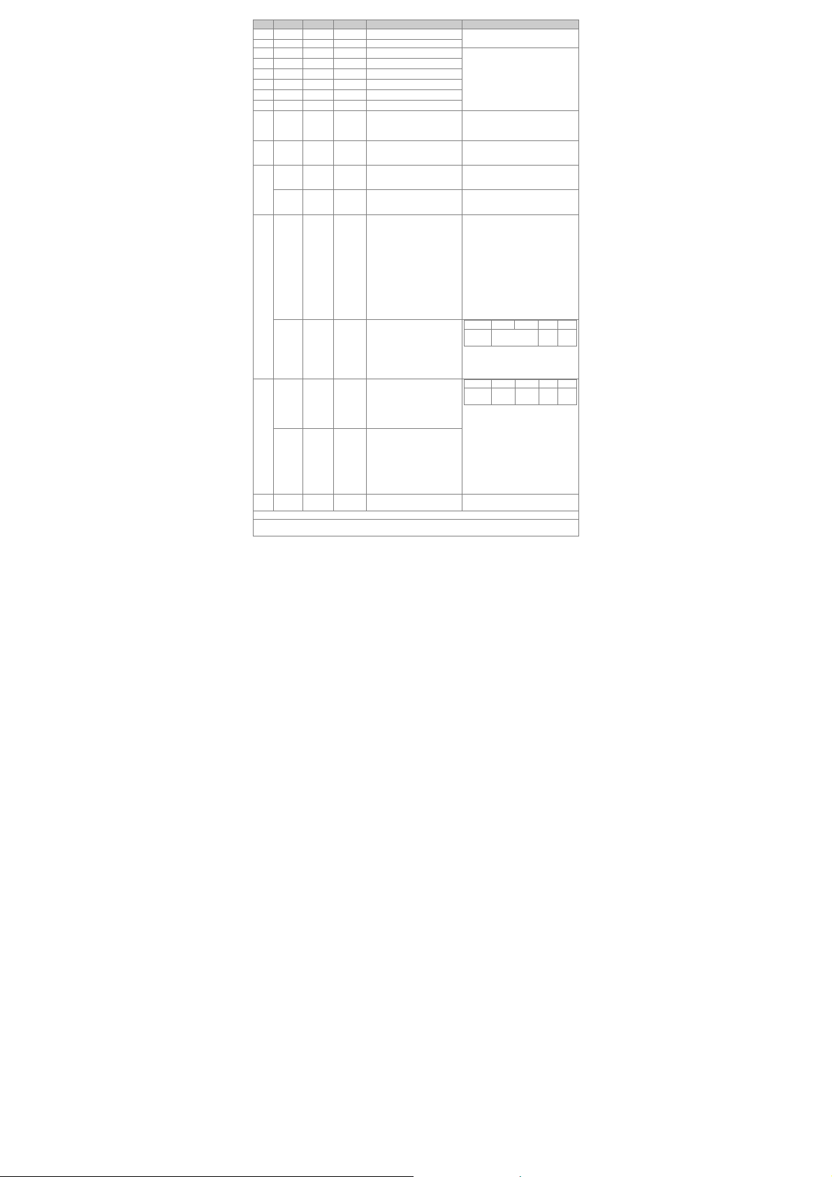
1. CR#30 hata kodu (error code) register. Aşağıdaki tabloyu inceleyiniz:
CR# Adres Kalıcı Özellik Register içeriği Açıklama
#0 H’4064 O R
#1 H’4065 X R/W CH1~CH4 Mod ayarı
H’4066
#2
--
#3 H’4067 O H’4067
#4 H’4068 O H’4068
digital I/O işgal etmezler.
2-telli/3-telli Pt100 / Pt1000 3850 PPM/ °C (DIN 43760 JIS C1604-1989)
/ Ni100 / Ni1000 / LG-Ni1000 / Cu100 / Cu50/ 0 ~300Ω / 0~3000Ω
0.6% tam skala 0 ~ 55°C (32 ~ 131°F)’de
Digital ve analog devreler arasında izolasyon mevcut. Kanallar arası
izolasyon yok.
500VDC Dijital devreler ve Toprak (Ground) arasında
500VDC Analog devreler ve Toprak (Ground) arasında
500VDC Analog devreler ve Dijital devreler arası nda
500VDC 24VDC ve Toprak (Ground) arasında
Desteklenir. ASCII/RTU mod. Varsayılan haberleşme formatı: 9600, 7, E,
1, ASCII; haberleşme formatı detayları için CR#32 bakınız.
Not1: PLC CPU'suna bağlandığında RS-485 k ullanılamaz.
Not 2: RS-485 iletişim kurulumları konus unda daha fazla ayrıntı için DVP
programlama kılavuzunun Ek E iç eriğindeki İnce Tip Özel Modül
İletişimleri kısmına başvurun.
O R/W
Model adı
(Sistemden ayarlıdır)
DVP04PT-S:
CH1 ortalama adet
DVP06PT-S:
CH1~CH4 ortalama adet
DVP04PT-S:
CH2 ortalama adet
DVP04PT-S:
CH3 ortalama adet
DVP04PT-S model kod= H’8A
DVP06PT-S model kod= H’CA
b15~12 b11~8 b7~4 b3~0
CH4 CH3 CH2 CH1
Örneğin CH1 için (b3,b2,b1,b0)
1. (0,0,0,0): Pt100 (default)
2. (0,0,0,1): Ni100
3. (0,0,1,0): Pt1000
4. (0,0,1,1): Ni1000
5. (0,1,0,0): LG-Ni1000
6. (0,1,0,1): Cu100
7. (0,1,1,0): Cu50
8. (0,1,1,1): 0~300 Ω
9. (1,0,0,0): 0~3000 Ω
10. (1,1,1,1): Bu kanal pasif.
Mod 8 ve 9 yalnızca DVP04PT-S
V4.16 veya üstü sürümü ve
DVP06PT-S V4.12 veya üstü
sürümü için kullanılabilir.
CH1 “Ortalama” sıcaklığın
hesaplanmasında kullanılacak
okuma adet sayısı.
Ayar aralığı: K1~K20.
Default ayarı K10.
CH1 ~ 6 “Ortalama” sıcaklığın
hesaplanmasında kullanılacak
okuma adet sayısı.
Ayar aralığı: K1~K20.
Default ayarı K10.
CH2 “Ortalama” sıcaklığın
hesaplanmasında kullanılacak
okuma adet sayısı.
Ayar aralığı: K1~K20.
Default ayarı K10.
CH3“Ortalama” sıcaklığın
hesaplanmasında kullanılacak
okuma adet sayısı.
Ayar aralığı: K1~K20.
Default ayarı K10.
- 15 -
Page 17

CR# Adres Kalıcı Özellik Register içeriği Açıklama
#5 H’4069 O H’4069
#6 H’406A X R CH1 Ortalama Sıcaklık
#7 H’406B X R CH2 Ortalama Sıcaklık
#8 H’406C X R CH3 Ortalama Sıcaklık
#9 H’406D X R CH4 Ortalama Sıcaklık
#10 -- X R CH5 Ortalama Sıcaklık
#11 -- X R CH6 O rtalama Sıcaklık
#12 H’4070 X R CH1 Ortalama Sıcaklık
#13 H’4071 X R CH2 Ortalama Sıcaklık
#14 H’4072 X R CH3 Ortalama Sıcaklık
#15 H’4073 X R CH4 Ortalama Sıcaklık
#16 -- X R CH5 Ortalama Sıcaklık
#17 -- X R CH6 Ortalama Sıcaklık
#18 H’4076 X R CH1 Mevcut Sıcaklık
#19 H’4077 X R CH2 Mevcut Sıcaklık
#20 H’4078 X R CH3 Mevcut Sıcaklık
#21 H’4079 X R CH4 Mevcut Sıcaklık
#22 -- X R CH5 Mevcut Sıcaklık
#23 -- X R CH6 Mevcut Sıcaklık
#24 H’407C X R CH1 Mevcut Sıcaklık
#25 H’407D X R CH2 Mevcut Sıcaklık
#26 H’407E X R CH3 Mevcut Sıcaklık
#27 H’407F X R CH4 Mevcut Sıcaklık
#28 -- X R CH5 Mevcut Sıcaklık
#29 -- X R CH6 Mevcut Sıcaklık
#29 H’4081 X R/W
#30 H’4082 X R Hata Durumu
H’4083 O R/W
#31
-- X R/W
H’4084 O R/W
32
-- X R/W
H’4085 O R/W
#33
-- X R/W DVP06PT-S:
DVP04PT-S:
CH4 ortalama adet
DVP04PT-S:
PID mod ayarı
DVP04PT-S:
Haberleşme Adresi Ayarı
DVP06PT-S:
CH5~CH6 Mod ayarı
DVP04PT-S:
Haberleşme formatı ayarı
DVP06PT-S:
CH5~CH6
Error LED ayarı
DVP04PT-S:
CH1~CH4
Fabrika ayarlarına reset ve
Error LED ayarı
- 16 -
CH4 “Ortalama” sıcaklığın
hesaplanmasında kullanılacak
okuma adet sayısı.
Ayar aralığı: K1~K20.
Default ayarı K10.
DVP04PT-S:
CH1 ~ 4 Ortalama Sıcaklık Okuma
(Birim: 0.1°C/0.01Ω(0~300Ω)
/0.1Ω(0~3000Ω).
DVP06PT-S:
CH1 ~ 6 Ortalama Sıcaklık Okuma
(Birim: 0.1°C/0.01Ω(0~300Ω)
/0.1Ω(0~3000Ω).
DVP04PT-S:
CH1 ~ 4 Ortalama Sıcaklık Okuma
(Birim: 0.1°C/0.01Ω(0~300Ω)
/0.1Ω(0~3000Ω).
DVP06PT-S:
CH1 ~ 6 Ortalama Sıcaklık Okuma
(Birim: 0.1°C/0.01Ω(0~300Ω)
/0.1Ω(0~3000Ω).
DVP04PT-S:
CH1 ~ 4 Mevcut Sıcaklık Okuma
(Birim: 0.1°C/0.01Ω(0~300Ω)
/0.1Ω(0~3000Ω).
DVP06PT-S:
CH1 ~ 6 Mevcut Sıcaklık Okuma
(Birim: 0.1°C).
DVP04PT-S:
CH1 ~ 4 Mevcut Sıcaklık Okuma
(Birim: 0.1°F).
DVP06PT-S:
CH1 ~ 6 Mevcut Sıcaklık Okuma
(Birim:
0.1°C/0.01Ω(0~300Ω)/0.1Ω(0~300
0Ω).
PID mod için H’5678 olarak
ayarlanır. Diğer değerler normal
mod.
Default ayarı H’0000.
Data register hata durumunu
kaydeder. Hata kodları bölümünü
inceleyiniz.
RS-485 haberleşme adresi ayarı;
ayar aralığı: 01~254. Default: K1
CH5 mod: b0 ~ b3
CH6 mod: b4 ~ b7
Bilgi için CR#1 inceleyiniz.
İletişim biçimini ayarlamak için
kullanılır.
Veri iletişim hızına yönelik ayarlar
4.800/9.600/19.200/38.400/57.600/
115.200 bps şeklindedir.
İletişim biçimi:
ASCII: 7,E,1 / 7,O,1 / 8,E,1 / 8,O,1 /
8,N,1
RTU: 8,E,1 / 8,O,1 / 8,N,1
Fabrika varsayılanı
ASCII,9600,7,E,1 (CR#32=H’0002)
Daha fazla bilgi için bu tablonun
sonundaki ※CR#32 iletişim biçimi
ayarları kısmına başvurun.
b15~12 b11~9 b8~6 b5~3 b2~0
ERR
rezerve CH6 CH5
LED
b12~13 ON olduğu zaman CH5~6
karşılık gelir, ölçüm aralığı aşıldığı
zaman Error LED flash yapar.
b15~12 b11~9 b8~6 b5~3 b2~0
ERR
CH4 CH3 CH2 CH1
LED
Eğer b2~b0 – 1,0,0 ayarlanırsa,
CH1 ayarları fabrika değerine
Page 18

CR# Adres Kalıcı Özellik Register içeriği Açıklama
#34 H’4086 O R Yazılım versiyonu
#35 ~ #48 Sistem kullanır
Semboller: O kalıcı. X kalıcı değil. R FROM k omutu ile veya RS-485’ten okunabilir data.
W TO komutu ve RS-485 ile yazılabilir data.
※ Aygıt yazılımı V4.16 (04PT-S) veya üstü sürüme sahip modüller iç in RESET işlevi eklendi. Modül güç
girişini 24 VDC kısmına bağlayın, CR# 0'a H’4352 yazın ve gücü kapatıp tekrar aç ın; modüllerdeki,
iletişim parametrelerini de içeren tüm parametreler fabrika varsayılanlarına döndürülür.
※ Modbus adresini ondalık biçimde kullanmak isterseniz, bir onaltılık ka ydediciyi ondalık biçim e
aktarabilir ve ondalık bir Modbus k aydedici adresi hâline getirmek için bir ekleyebilirsiniz. Ör neğin
CR#0'ın onaltılık biçimdeki “H’4064” adr esini ondalık biçime aktarmak 16484 sonucunu verir ve bir
eklendiğinde ondalık biçimdeki 1648 5 Modbus adresini elde edersini z.
※ CR#32 iletişim biçimi ayarları: Aygıt yazılımı V4.14 (04PT-S) veya önceki sürümler e sahip modüller
içindir, b11~b8 veri biçimi seçimi kullanılamaz. Biçim , ASCII mod için 7, E, 1 (H’00XX) ve RTU m odu
için 8, E, 1 (H’C0xx/H’80xx) olarak sabitlen ir. Aygıt yazılımı V4.15 (04PT-S) veya üstü sürüme sahip
modüller için kurulumlara yöne lik olarak aşağıdaki tabloya başvurun. H’C0XX/H’80XX orijinal
kodunun, aygıt yazılımı V4.15 (04PT-S) veya üstü sürü me sahip modüller için RTU, 8, E, 1 olarak
görüneceğine dikkat edin.
b15 ~ b12 b11 ~ b8 b7 ~ b0
ASCII/RTU,
CRC kontrol kodunun düşük ve
yüksek baytını takas edin
H'0 ASCII H'0 7,E,1*1 H'01 4800 bps
H'8
H'C
Not *1: Bu yalnızca ASCII biçimi için kullanılab ilir.
Örnek: RTU'nun bir sonucu için CR#32'ye H’C310 yazın, 8,N,1 CRC kontrol kodunun düşük ve yüksek
CR#30 Hata kodu registeri.
Not: Her bir hata kodu bir bite karşılık gelir ve 16-bit binary sayıya çevrilmelidir (Bit0~15). İki veya
daha fazla hata aynı anda meydana gelebili r. Lütfen Aşağıdaki tabloyu inceleyiniz.:
numarası
Açıklama
numarası
Açıklama Hardware hatası Rezerve
numarası
Açıklama
numarası
Açıklama
RTU,
CRC kontrol kodunun
düşük ve yüksek baytını
takas etme yin
RTU,
CRC kontrol kodunun
düşük ve yüksek baytını
takas edin
baytını takas edin ve veri iletişim hı zını 57600 bps değerine ayarlayın.
Bit
Güç kaynağı
Bit
Bit
Bit
anormal
CH1 Anormal
dönüşüm
CH5 Anormal
dönüşüm
CH1~CH4
Fabrika ayarlarına reset ve
CH1~CH4 Error LED ayarı
Veri biçimi Veri iletişim hızı
Açıklama
H'1 8,E,1 H'02 9600 bps
H'2 ayrılmış H'04 19200 bps
H'3 8,N,1 H'08 38400 bps
H'4 7,O,1*1 H'10 57600 bps
H'5 8.O,1 H'20 115200 bps
0 1 2 3
4 5 6 7
8 9 10 11
12 13 14 15
Kontak hiçbir
yere bağlı değil.
CH2 Anormal
dönüşüm
CH6 Anormal
dönüşüm
döner. CH1~4 fabrika ayarına
alınmak istenirse b11~b0 H’924
ayarlanmalıdır. (DVP04PT-S, tek ve
tüm kanalları sıfırlamayı destekler;
DVP06PT-S, yalnızca tüm kanalları
sıfırlamayı destekler).
b12~15 ON olduğu zaman CH1~4
karşılık gelir, ölçüm aralığı aşıldığı
zaman Error LED flash yapar.
Heksadesimal olarak versiyonu
gösterir. Ör: H’010A = versiyon
1.0A
Rezerve Rezerve
Ortalama adet
hatası
CH3 Anormal
dönüşüm
Rezerve Rezerve
Komut hatası
CH4 Anormal
dönüşüm
- 17 -
Page 19

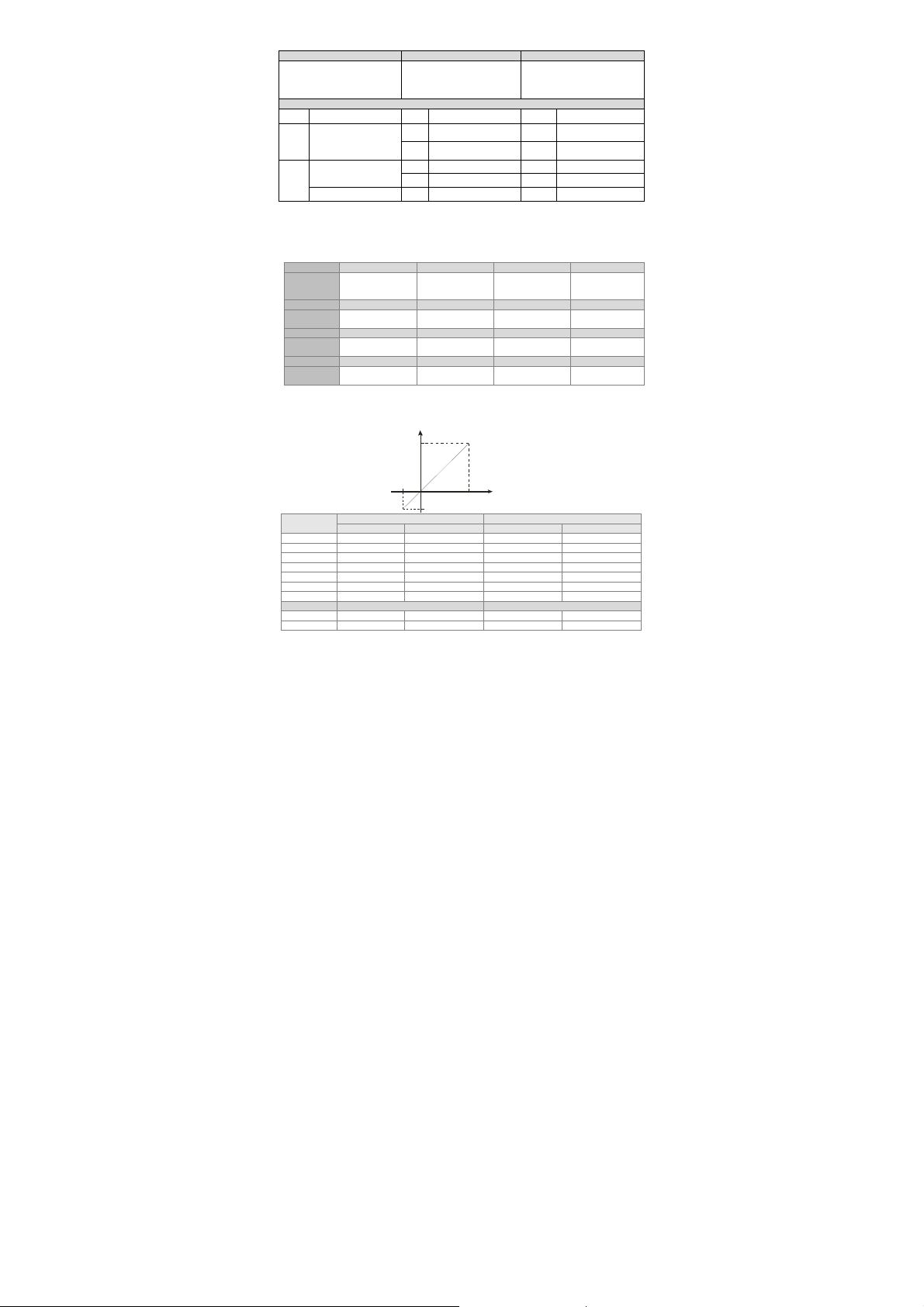
Sıcaklık/Dijital Değer Karakteristik Eğrisi
Santigrat (Fahrenhayt) sıcaklık ölçme modu:
Digital output
Max .
Min .
Algılayıcı
Pt100 -180 ~ 800°C -292 ~ 1,472°F K-1,800 ~ K8,000 K-2,920 ~ K14,720
Ni100 -80 ~ 170°C -112 ~ 338°F K-800 ~ K1,700 K-1,120 ~ K3,380
Pt1000 -180 ~ 800°C -292 ~ 1, 472°F K-1,8 00 ~ K8,000 K-2,920 ~ K14,720
Ni1000 -80 ~ 170°C -112 ~ 338°F K-800 ~ K1,700 K-1,120 ~ K3,380
LG-Ni1000 -60 ~ 200°C -76 ~ 392°F K-600 ~ K2,000 K-760 ~ K3,920
Sıcaklık aralığı Dijital değer dönüşüm aralığı
°C (Min./Max.) °F (Min./Max.) °C (Min./Max.) °F (Min./Max.)
Min.
Max.
Temperature input
Cu100 -50 ~ 150°C -58 ~ 302°F K-500 ~ K1,500 K-580 ~ K3,020
Cu50 -50 ~ 150°C -58 ~ 302°F K-500 ~ K1,500 K-580 ~ K3,020
Algılayıcı Giriş direnc i aralığı Dijital değer dönüşüm aralığı
0~300Ω 0Ω ~ 320Ω K0 ~ 32000 0~300Ω 0Ω ~ 320Ω
0~3000Ω 0Ω ~ 3200Ω K0 ~ 32000 0~3000Ω 0Ω ~ 3200Ω
- 18 -
 Loading...