

Page 1
2010-12-22
11
7
-PT
DVP-1070570-01
Page 2
………………………………………………………………… ENGLISH …………………………………………………………………
DVP04PT-H2 is able to receive 4 points of resistance temperature detectors (PT100,
PT1000, NI100, and NI1000) and convert them into 16-bit digital signals. Besides,
through the user of FROM/TO instructions in DVP-EH2 MPU program, the data in
DVP04PT-H2 can be read or written. There are 49 16-bit control registers (CR) in it.
DVP04PT-H2 displays temperatures in Celsius (resolution: 0.1°C) and Fahrenheit
(resolution: 0.1°F).
a This instruction sheet only provides descriptions on electrical specifications, general
specifications, installation and wiring. For detailed infromation about programming
and intructions, please see DVP-PLC Application Manual: Programming. For more
information about the optional peripherals, please see individual product instuction
sheet or DVP-PLC Application Manual: Special Modules.
a DVP04PT-H2 is an OPEN-TYPE device and therefore should be installed in an
enclosure free of airborne dust, humidity, electric shock and vibration. The enclosure
should prevent non-maintenance staff from operating the device (e.g. key or specific
tools are required to open the enclosure) in case danger and damages on the device
may occur.
a DO NOT connect the input AC power supply any of the I/O terminals; otherwise
serious damanges may occur. Check all the wirings again before switching on the
power. Make sure the ground terminal is correctly grounded in order to eliminate
electromagnetic noises. DO NOT touch the terminals when the power is switched on.
a Keep the wire between the RTD and PLC as short as possible and the power cable
as far away as possible from the I/O to prevent interferences.
a When setting up the PLC to resistance temperature detectors mode, please make
sure the setting of CR#1 is correct, or it will cause serious errors.
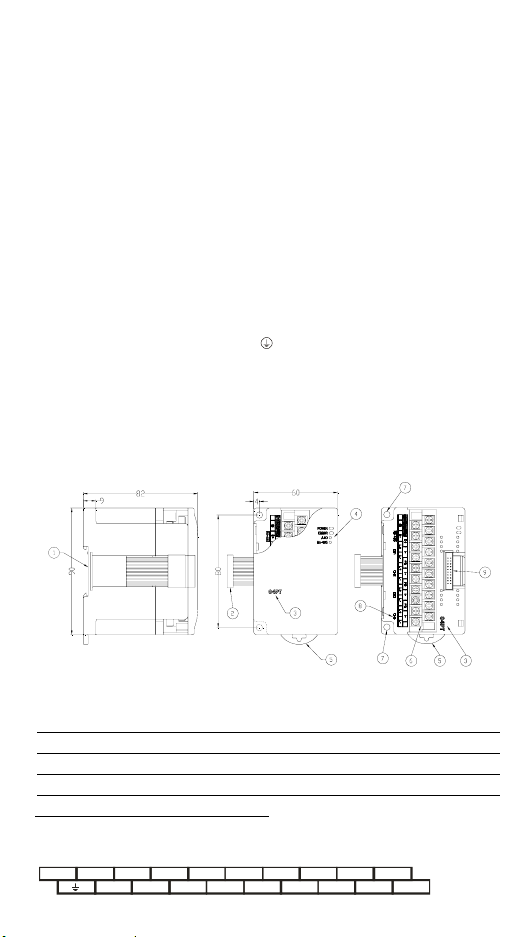
Product Profile & Dimensions
Unit: mm
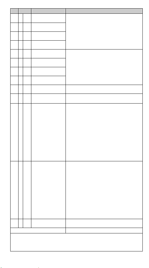
1. DIN rail (35mm) 6. Terminals
2. Connection port for extension module 7. Mounting hole
3. Model name 8. I/O terminals
4. POWER, ERROR, A/D indicator 9. Mounting port for extension module
5. DIN rail clip
I/O Terminal Layout
24V 0V
D + I -
D - L + L - L +
FGI -FGI -FGI -
CH1 CH2 CH 3 CH4RS-485
L - L + L - L + L -
- 1 -
[Figure 1]
Page 3
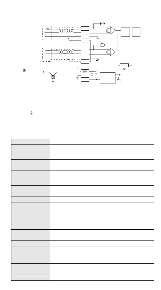
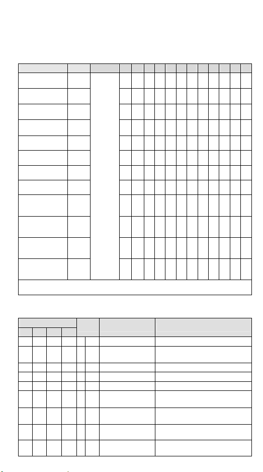
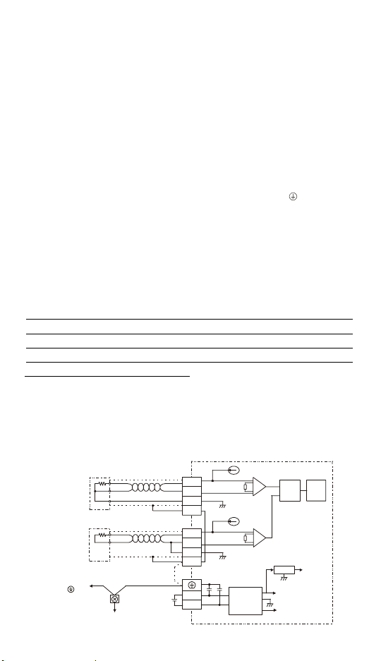
External Wiring
A
PT100/PT1000
NI100/NI10 00
3 wir e
PT100/PT1000
NI100/NI10 00
2 wir e
Termin al of
power module
*1: Wiring for analog inputs should use cables of resistive temperature sensors or double shielding
cables and should be separated from other power cables that may cause interferences. To prevent the
measuring results from being affected by the line resistance, use 3-wire temperature sensor. The
terminals should be screwed at torque 1.95 kg-cm (1.7 in-lbs).
*2: Terminal FG is the ground location for noise suppression.
*3: Connect
and ground the system contact or connect it to the cover of power distribution cabinet.
Note: DO NOT wire empty terminals. Use 60/75°C copper conductors only.
Ear th (100 o r less )
terminal on both the power supply module and DVP04PT-H2 to the system earth point
Shielding
cable *1
Shielding
cable *1
*3
System
grounding
Ω
CH1
CH4
*2
24+
L+
L-
I-
AG
FG
L+
L-
I-
AG
FG
AG
DC/ DC
Converter
0V
+15V
AG
-15V
Electrical Specifications
Power supply voltage 24 VDC (20.4 to 28.8 VDC) (-15 to +20%)
Analog output channel 4 channels/module
Applicable sensors
Current excitation 1.53 mA/200 μA
Range of input temp. See the table in “Temperature/Digital Value Curve” section.
Range of digital
conversion
Resolution 16-bit (0.1°C/0.1°F)
Output impedance 0.5Ω or less
Overall accuracy
Response time 400 ms × number of channels
Isolation
Format of digital data 15 sig nificant bits out of 16 bits are available; in 2’s complement
Average function Provided; available for setup in CR#2 to CR#5; Range: K1 to K100
Self-diagnosis Upper and lower bound detection/channel
Communication mode
(RS-485)
Serial connection with
DVP-PLC MPU
3-WIRE PT100 / NI100 / PT1000 / NI1000 3850 PPM/°C (DIN 43760
JIS C1604-1989)
See the table in “Temperature/Digital Value Curve” section.
±0.6% when in full scale within the range of 0 to 55°C, 32 to 131°F
Isolation between digital circuits and analog circuits. Isolation
between channels.
500 VDC between digital circuits and ground
500 VDC between analog circuits and ground
500 VDC between analog circuits and digital circuits
500 VDC between 24 VDC and ground
ASCII/RTU mode. Communication speed: 4,800 / 9,600 / 19,200 /
38,400 / 57,600 / 115,200 bps. ASCII data format: 7-bit, even bit, 1
stop bit (7, E, 1). RTU data format: 8-bit, even bit, 1 stop bit (8, E, 1).
RS-485 cannot be used when connected to PLC MPU.
The modules are numbered from “0 to 7” automatically by their
distance from MPU. 0 is the closest to MPU and 7 is the furthest.
Maximum 8 modules are allowed to connect to the PLC and will not
occupy any digital I/O points.
- 2 -
MUX
DC
5V
Page 4
Other Specifications
Max. rated power
consumption
Operation/storage
Vibration/shock
immunity
24 VDC (20.4 to 28.8 VDC) (-15 to +20%), 2.5 W supplied by external
power.
1. Operation: 0 to 55°C (temperature), 50 to 95% (humidity), pollution
degree 2
2. Storage: -25 to 70°C (temperature), 5 to 95% (humidity)
Standard: IEC61131-2, IEC 68-2-6 (TEST Fc)/IEC61131-2 & IEC
68-2-27 (TEST Ea)
Power supply
Environment
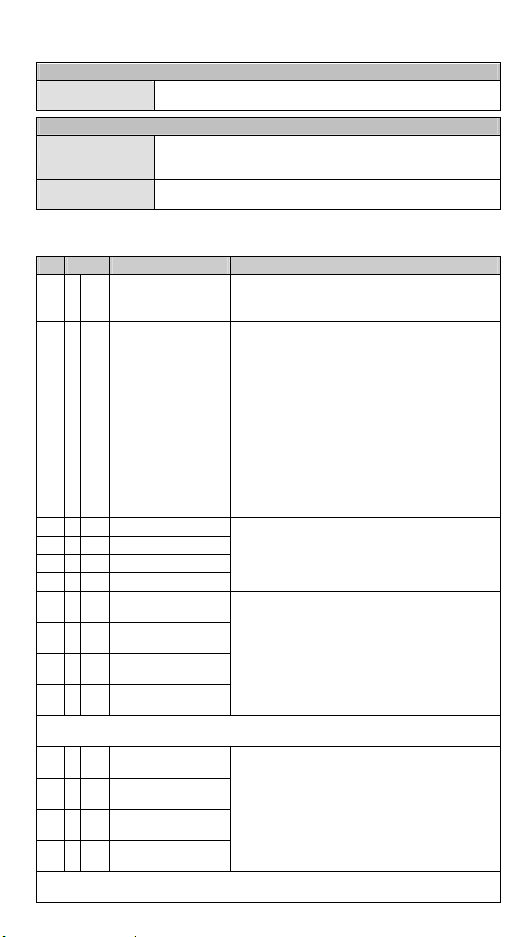
Control Register
CR# Attrib. Content Explanation
#0 O R Model name
#1 O R/W Modes of CH1 ~ CH4
#2 O R/W CH1 average time
#3 O R/W CH2 average time
#4 O R/W CH3 average time
#5 O R/W CH4 average time
#6 X R
#7 X R
#8 X R
#9 X R
CR#6 to CR#9 are the average Celsius temperatures measured at CH1 to CH4 obtained from
the average time settings in CR#2 ~ CR#5.
#12 X R
#13 X R
#14 X R
#15 X R
CR#12 to CR#15 are the average Fahrenheit temperatures measured at CH1 to CH4 obtained
from the average time settings in CR#2 to CR#5.
Average °C temp.
measured at CH1
Average °C temp.
measured at CH2
Average °C temp.
measured at CH3
Average °C temp.
measured at CH4
Average °F temp.
measured at CH1
Average °F temp.
measured at CH2
Average °F temp.
measured at CH3
Average °F temp.
measured at CH4
Set up by the system. DVP04PT-H2 = H’6402.
You can read the model name from the program and
see if the module exists.
CH1 mode: b0 ~ b3
CH2 mode: b4 ~ b7
CH3 mode: b8 ~ b11
CH4 mode: b12 ~ b15
Take setting up (b3, b2, b1, b0) of CH1 for example
(Default = H’0000):
1. (0, 0, 0, 0): PT100
2. (0, 0, 0, 1): NI100
3. (0, 0, 1, 0): PT1000
4. (0, 0, 1, 1): NI1000
5. (0, 1, 0, 0): 0 to 300Ω
6. (0, 1, 0, 1): 0 to 3,000Ω
7. (1, 1, 1, 1): Disabled
Range of settings in CH1 to CH4: K1 to K100.
Default =K10.
Please note that the average times set in CR#2 to
CR#5 can only be written in once.
Average Celsius temperature measured at CH1 ~
CH4.
Unit: 0.1°C
Average Fahrenheit temperature measured at CH1 ~
CH4.
Unit: 0.1°F
- 3 -
Page 5
CR# Attrib. Content Explanation
#18 X R
#19 X R
#20 X R
#21 X R
#24 X R
#25 X R
#26 X R
#27 X R
#30 X R Error status
#31 O R/W
#32 O R/W
#33 O R/W
#34 O R Firmware version
#35 ~ #48 For system use
Symbols:
O: Latched, X: Non-latched
R: Able to read data by using FROM instruction or RS-485 communication.
W: Able to write data by using TO instruction or RS-485 communication.
c CR#0 ~ CR#34: The corresponding parameter addresses H’4064 ~ H’4086 are for
users to read/write data by RS-485 communication. When using RS-485, you have to
Present °C temp.
measured at CH1
Present °C temp.
measured at CH2
Present °C temp.
measured at CH3
Present °C temp.
measured at CH4
Present °F temp.
measured at CH1
Present °F temp.
measured at CH2
Present °F temp.
measured at CH3
Present °F temp.
measured at CH4
Communication
address
Communication speed
(baudrate)
Returning to default
setting
Present Celsius temperature measured at CH1 ~
CH4.
Unit: 0.1°C
Present Fahrenheit temperature measured at CH1 ~
CH4.
Unit: 0.1°F
Register for storing all error statuses. See the table of
error status for more information.
The RS-485 communication addresses.
Range: 01 to 254, Default = K1.
Available baudrates: 4,800/9,600/19,200/
38,400/57,600/115,200 bps. ASCII data format: 7-bit,
even bit, 1 stop bit (7, E, 1). RTU data format: 8-bit,
even bit, 1 stop bit (8, E, 1). Default = H’0002.
b0: 4,800 bps
b1: 9,600 bps (default)
b2: 19,200 bps
b3: 38,400 bps
b4: 57,600 bps
b5: 115,200 bps
b14: High/low bit exchange of CRC checksum (only
valid in RTU mode)
b15: Switch between ASCII/RTU modes; 0 = ASCII
mode (default)
Take the setting of CH1 for example:
b0: Reserved, b1: Reserved
When b2 is set to 1, all settings will return to default
ones.
Definitions of ERR LED:
(Default of b12 to b15 = 1111)
1. When b12 = 1 and CH1 wired to empty external
contact, ERR LED will flash.
2. When b13 = 1 and CH2 wired to empty external
contact, ERR LED will flash.
3. When b14 = 1 and CH3 wired to empty external
contact, ERR LED will flash.
4. When b15 = 1 and CH2 wired to empty external
contact, ERR LED will flash.
Displaying the current firmware version in hex; e.g.
version 1.0A is indicated as H’010A
- 4 -
Page 6
first separate the module from the PLC MPU.
1. Function: H’03 (read register data); H’06 (write 1 word datum into register); H’10
(write many word data into register).
2. The latched CR should be written by RS-485 communication to stay latched. The
CR will not be latched if written by MPU through TO/DTO instruction
CR#30: Error status
Error status Va lu e
Abnormal power
supply
Wired to empty
external contact
Incorrect mode
setting
OFFSET/GAIN
error
Hardware
malfunction
Abnormal digital
range
Incorrect average
times setting
Instruction error
CH1 wired to
empty external
contact
CH2 wired to
empty external
contact
CH3 wired to
empty external
contact
CH4 wired to
empty external
contact
Note: Each error status is determined by the corresponding bit (b0 ~ b11) and there may be more
than 2 errors occurring at the same time. 0 = normal; 1 = error.
b15 ~ b12 b11 b10 b9 b8 b7 b6 b5 b4 b3 b2 b1 b0
K1
(H’1)
K2
(H’2)
K4
(H’4)
K8
(H’8)
K16
(H’10)
K32
(H’20)
K64
(H’40)
K128
(H’80)
K256
(H’100)
K512
(H’200)
K1024
(H’400)
K2048
(H’800)
Reserved
0 0 0 0 0 0 0 0 0 0 0 1
0 0 0 0 0 0 0 0 0 0 1 0
0 0 0 0 0 0 0 0 0 1 0 0
0 0 0 0 0 0 0 0 1 0 0 0
0 0 0 0 0 0 0 1 0 0 0 0
0 0 0 0 0 0 1 0 0 0 0 0
0 0 0 0 0 1 0 0 0 0 0 0
0 0 0 0 1 0 0 0 0 0 0 0
0 0 0 1 0 0 0 0 0 0 0 0
0 0 1 0 0 0 0 0 0 0 0 0
0 1 0 0 0 0 0 0 0 0 0 0
1 0 0 0 0 0 0 0 0 0 0 0
PID Control Registers
CR#
CH1 CH2 CH3 CH4
#51 #71 #91 #111 O R/W Temperature SV Default = K0.
#52 #72 #92 #112 O R/W Sampling time
#53 #73 #93 #113 O R/W KP Default = K121
#54 #74 #94 #114 O R/W KI Integral constant, Default = K2,098.
#55 #75 #95 #115 O R/W KD Derivative constant, Default = K-29.
#56 #76 #96 #116 O R/W Upper limit of I value
#57 #77 #97 #117 O R/W Lower limit of I value
#58 #78 #98 #118 X R I value
#59 #79 #99 #119 O R/W
Latched Content Explanation
Range: K1 to K30, Unit: s
Default = K2.
Range: K-32,760 to K32,760
Default = K0.
Range: K-32,760 to K32,760
Default = K0.
Current accumulated offset value.
Heating/cooling
control
Default = K0.
0: Heater, 1: Cooler. Default = K0.
- 5 -
Page 7
CR#
CH1 CH2 CH3 CH4
#60 #80 #100 #120 O R/W Upper limit of output
#61 #81 #101 #121 O R/W Lower limit of output
#62 #82 #102 #122 X R Output percentage
#63 #83 #103 #123 X R Output width
#64 #84 #104 #124 X R Output cycle
#65 #85 #105 #125 X R Output volume Default = K0
#66 #86 #106 #126 X R/W PID_Run/Stop 0: Stop, 1: Run. Default = K0.
#67 #87 #107 #127 X R/W Auto Tune
Latched Content Explanation
Range: K-32,760 to K32,760
Default = K4,000.
Range: K-32,760 to K32,760
Default = K0. .
Range: K0 to K1,000, Unit: 0.1%.
Default = K0.
Width of control output, Unit: ms.
Default = K0.
Cycle of control output, Unit: ms.
Default = K0.
0: Disabled, 1: Auto-tuning
Default = K0.
c The CR# listed above do not support RS-485 read/write.
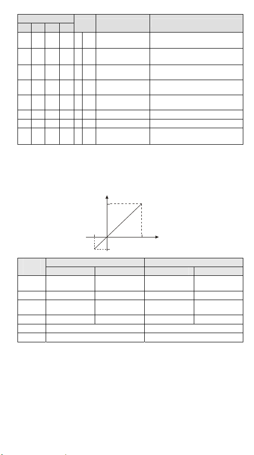
Temperature / Digital Value Curve
°C/°F Temperature Measurement Mode:
Digital output
Max.
Min.
Min.
Thermo
-couple
PT100 -180 to 800°C -292 to 1,472°F K-1,800 t o K8,000
NI100 -80 to 170°C -112 to 338°F K-800 to K1,700 K-1,120 to K3,380
PT1000 -180 to 800°C -292 to 1,472°F K-1,800 to K8,000
NI1000 -80 to 170°C -112 to 338°F K-800 to K1,700 K-1,120 to K3,380
300 Ω 0 to 300 Ω K0 to K30,000
3k Ω 0 to 3,000 Ω K0 to K30,000
Range of input temperature Range of digital conversion
°C (Min. / Max.) °F (Min. / Max.) °C (Min. / Max.) °F (Min. / Max.)
Max.
Measured
temperature input
- 6 -
K-2,920 to
K14,720
K-2,920 to
K14,720
Page 8

………………………………………………………………… 繁體中文 ………………………………………………………………………
A
A
DVP04PT-H2 溫度量測模組可接受外部 4 點電阻式溫度感測器(PT100/ PT1000/ NI100/
NI1000),將之轉換成 16 位元之數位信號。透過 DVP- EH2 系列 PLC 主機程式以指令
FROM/TO 來讀寫模組內之資料,模組內具有49 個 CR (Control Register) 暫存器,每個
暫存器有 16 bits。使用者可選擇攝氏溫度或華氏溫度,攝氏溫度輸入解析度為 0.1°C,華
氏溫度輸入解析度為 0.1°F。
a 本使用說明書僅提供電氣規格、功能規格、安裝配線部份說明,其它詳細之程式設計
及指令說明請見《DVP-PLC 應用技術手冊:程式篇》,選購之週邊裝置詳細說明請見
該產品隨機手冊或《DVP-PLC 應用技術手冊:特殊模組篇》。
a 本機為開放型(OPEN TYPE)機殼,因此使用者使用本機時,必須將之安裝於具防塵、
防潮及免於電擊/衝擊意外之外殼配線箱內。另必須具備保護措施(如:特殊之工具或
鑰匙才可打開)防止非維護人員操作或意外衝擊本體,造成危險及損壞。
a 交流輸入電源不可連接於輸入∕出信號端,否則可能造成嚴重損壞,請在上電之前再
次確認電源配線。請勿在上電時觸摸任何端子。本體上之接地端子 務必正確的接
地,可提高產品抗雜訊能力。
a 由測溫體到溫調本體的配線路請用最短距離配線,為了避免雜訊及誘導的影響儘可能
將電源線和負載配線分開。
a 電阻式溫度感測器之設定,請檢查 CR#1,如設定錯誤會造成量測重大誤差。
產品外觀尺寸與部位介紹
y 詳細外觀及尺寸圖表請參閱英文版頁碼 1 之[Figure 1],單位:mm。
1. DIN 導軌槽 (35mm) 6. 端子
2. 擴充模組連接口 7. 固定孔
3. 機種名稱 8. 端子配置
4. 電源、錯誤及轉換指示燈 9. 擴充模組連接座
5. DIN 軌固定扣
輸入∕輸出端子台配置
請參閱英文版頁碼 1 之端子配置,在此語言版本省略說明。
外部配線
PT100/PT1000
NI100/NI1000
線式
3
PT100/PT1000
NI100/N I1000
2
線式
接至電源模
組之 端
第三種接地
(100 )
接地抗阻 以下Ω
隔離線
隔離線
*3
系統接地點
CH1
*1
L+
L-
I-
FG
*1
CH4
L+
L-
I-
FG
*2
24+
0V
G
AG
DC/ DC
轉換器
AG
+15V
AG
-15V
MUX
DC
5V
- 7 -
Page 9

註 1:使用於類比輸入的配線應採用電阻式溫度感測器之連接線或雙絞隔離線且應與其他電源線
或可能引起雜訊之接線分開。為避免線阻影響測量結果,建議使用3 線式溫度感測器。端
子螺絲扭力為 1.95 kg-cm (1.7 in-lbs)。
註 2:如果雜訊過大,請將 FG 及接地端子連接。
註 3:請將電源模組之
統接點作第三種接地或接到配電箱之機殼上。
注意:空端子請勿配線。只能使用60/75°C 的銅導線。
端及DVP04PT-H2 溫度量測模組之 端連接到系統接地點,再將系
電氣規格
電源電壓 24 VDC (20.4 ~ 28.8 VDC) (-15 ~ +20%)
類比訊號輸出通道 4通道∕台
適合感應器形式
驅動電流 1.53mA∕200μA
輸入溫度範圍 請參閱溫度∕數位特性曲線附表
數位轉換範圍 請參閱溫度∕數位特性曲線附表
解析度 16-bit (0.1°C/0.1°F)
輸出阻抗 0.5Ω 或更低
總和精密度 ±0.6%在 0 ~ 55°C、32 ~ 131°F 範圍內滿刻度時
響應時間 400 ms × 通道數
隔離方式
數位資料格式 16 位元二補數,有效位 15 bits。
平均功能 有(CR#2 ~ CR#5 可設定,範圍 K1 ~ K100)
自我診斷功能 上下極限偵測∕通道
通訊模式(RS-485)
與 DVP-PLC 主機
串接說明
3 線 PT100 / NI100 / PT1000 / NI1000 3850 PPM/°C (DIN 43760 JIS
C1604-1989)
類比電路與數位電路之間隔離,通道間隔離。
數位電路與接地之間:500 VDC
類比電路與接地之間:500 VDC
類比電路與數位電路之間:500 VDC
24 VDC 與接地之間:500 VDC
包含 ASCII/ RTU 模式,通訊速率可選 (4,800 / 9,600 / 19,200 / 38,400 /
57,600 / 115,200),ASCII 模式資料格式固定為 7-bit、偶位元、1 stop bit
(7, E, 1),RTU 模式資料格式固定為 8-bit、偶位元、1 stop bit (8, E, 1)。
當與 PLC 主機串接時,RS-485 通訊無法使用。
模組編號以靠近主機之順序自動編號由 0 到 7,最大可連接 8 台且不佔用
數位 I/O 點數。
其他規格
電源規格
額定最大消耗功率 直流 24 VDC (20.4 ~ 28.8VDC) (-15 ~ +20%), 2.5W,由外部電源供應
操作∕儲存環境
耐振動∕衝擊
1. 操作:0 ~ 55°C(溫度),50 ~ 95%(濕度),污染等級 2
2. 儲存:-25 ~ 70°C(溫度),5 ~ 95%(濕度)
國際標準規範 IEC61131-2, IEC 68-2-6 (TEST Fc)/IEC61131-2 & IEC
68-2-27 (TEST Ea)
環境規格
- 8 -
Page 10

控制暫存器 CR
保持型 暫存器名稱 說明
CR#
#0 O R
#1 O R/W
#2 O R/W
#3 O R/W
#4 O R/W
#5 O R/W
#6 X R
#7 X R
#8 X R
#9 X R
CR#6 ~ CR#9:內容值為通道 CH1 ~ CH4 量測攝氏溫度信號以 CR#2 ~ CR#5 設定之平均次數
所取得之平均值。
#12 X R
#13 X R
#14 X R
#15 X R
CR#12 ~ CR#15:內容值為通道CH1 ~ CH4 量測華氏溫度信號以 CR#2 ~ CR#5 設定之平均次
數所取得之平均值。
#18 X R
#19 X R
#20 X R
#21 X R
#24 X R
#25 X R
#26 X R
#27 X R
#30 X R
#31 O R/W
#32 O R/W
機種型號
CH1 ~ CH4 模式設定
CH1 平均次數
CH2 平均次數
CH3 平均次數
CH4 平均次數
CH1 量測攝氏溫度平均值
CH2 量測攝氏溫度平均值
CH3 量測攝氏溫度平均值
CH4 量測攝氏溫度平均值
CH1 量測華氏溫度平均值
CH2 量測華氏溫度平均值
CH3 量測華氏溫度平均值
CH4 量測華氏溫度平均值
CH1 量測攝氏溫度現在值
CH2 量測攝氏溫度現在值
CH3 量測攝氏溫度現在值
CH4 量測攝氏溫度現在值
CH1 量測華氏溫度現在值
CH2 量測華氏溫度現在值
CH3 量測華氏溫度現在值
CH4 量測華氏溫度現在值
錯誤狀態
通訊位址設定
通訊速率設定
系統內定,DVP04PT-H2 機種編碼 = H’6402
使用者可在程式中將此機種型號讀出,以判斷擴充
模組是否存在。
CH1 模式:b0 ~ b3
CH2 模式:b4 ~ b7
CH3 模式:b8 ~ b11
CH4 模式:b12 ~ b15
以 CH1 設定(b3,b2,b1,b0) 說明,預設值 H’0000:
1. 設定為 (0,0,0,0) 時,選用 PT100。
2. 設定為 (0,0,0,1) 時,選用 NI100。
3. 設定為 (0,0,1,0) 時,選用 PT1000。
4. 設定為 (0,0,1,1) 時,選用 NI1000。
5. 設定為 (0,1,0,0) 時,選用 0 ~ 300Ω。
6. 設定為 (0,1,0,1) 時,選用 0 ~ 3,000Ω。
7. 設定為 (1,1,1,1) 時,Disable。
通道 CH1 ~ CH4 訊號的平均次數設定,可設定範圍
K1 ~ K100。出廠設定值為 K10。
請注意寫入平均次數設定於 CR#2 ~ CR#5 只須寫
入一次。
通道 CH1 ~ CH4 量測攝氏溫度平均值顯示
單位 0.1°C
通道 CH1 ~ CH4 量測華氏溫度平均值顯示
單位 0.1°F
通道 CH1 ~ CH4 量測攝氏溫度現在值顯示
單位 0.1°C
通道 CH1 ~ CH4 量測華氏溫度現在值顯示
單位 0.1°F
儲存所有錯誤狀態的資料暫存器,詳細內容請參照
錯誤信息表。
設定 RS-485 通訊位址,設定範圍 01 ~ 254。出廠
設定值為 K1。
設定通訊速率,共有 4,800/9,600/19,200
bps/38,400 bps/57,600 bps/ 115,200 bps 六種。
ASCII 模式資料格式固定為 7-bit、偶位元、1 stop bit
- 9 -
Page 11

保持型 暫存器名稱 說明
CR#
#32 O R/W
#33 O R/W
#34 O R
#35 ~ #48
符號定義:
O:停電保持型。 X:非停電保持型。
R:可使用 FROM 指令讀取資料,或利用 RS-485 通訊讀取資料。
W:可使用 TO 指令寫入資料,或利用 RS-485 通訊寫入資料。
通訊速率設定
恢復出廠設定
韌體版本 16 進制,顯示目前韌體版本,如 1.0A 則 H’010A
(7, E, 1),RTU 模式資料格式固定為 8- bit、偶位元、
1 stop bit (8, E, 1)。
出廠設定值為 H’0002。
b0: 4,800 bps(位元∕秒)
b1: 9,600 bps(位元∕秒)(出廠設定值)
b2: 19,200 bps(位元∕秒)
b3: 38,400 bps(位元∕秒)
b4: 57,600 bps(位元∕秒)
b5: 115,200 bps(位元∕秒)
b14: CRC 檢查碼高低位交換(僅 RTU 模式有效)
b15: ASCII/RTU 模式切換,0 為 ASCII(出廠設定
值)。
以 CH1 設定來說明:
b0 保留,b1 保留
b2 = 1 時,所有設定值將回復為出廠設定值。
ERR 燈定義:原廠設定值 b12 ~ b15 = 1111
1. 當 b12 = 1 時,CH1 外部接點空接時 ERR 燈閃
爍動作。
2. 當 b13 = 1 時,CH2 外部接點空接時 ERR 燈閃
爍動作。
3. 當 b14 = 1 時,CH3 外部接點空接時 ERR 燈閃
爍動作。
4. 當 b15 = 1 時,CH4 外部接點空接時 ERR 燈閃
爍動作。
系統內部使用
※ CR#0 ~ CR#34:對應之參數位址H’4064 ~ H’4086 可提供使用者利用 RS-485 通訊來
讀寫資料。由 RS-485 通訊時須先將模組與主機分離。
1. 功能碼 (Function):H’03 讀出暫存器資料。H’06 寫入一個word 資料至暫存器。H’10
寫入多筆 word 資料至暫存器。
2. 停電保持型的CR 須由 RS-485 通訊來寫入才有停電保持的功能,如果是由主機以
TO/DTO 指令寫入則不會有停電保持的功能。
CR#30:錯誤狀態值請參照錯誤狀態表
錯誤狀態 內容值 b15 ~ b12 b11 b10 b9 b8 b7 b6 b5 b4 b3 b2 b1 b0
電源異常
外部接點空接
模式設定錯誤
OFFSET/GAIN 錯
誤
硬體故障
變換值異常
K1
(H’1)
K2
(H’2)
K4
(H’4)
K8
(H’8)
K16
(H’10)
K32
(H’20)
保留
0 0 0 0 0 0 0 0 0 0 0 1
0 0 0 0 0 0 0 0 0 0 1 0
0 0 0 0 0 0 0 0 0 1 0 0
0 0 0 0 0 0 0 0 1 0 0 0
0 0 0 0 0 0 0 1 0 0 0 0
0 0 0 0 0 0 1 0 0 0 0 0
- 10 -
Page 12

錯誤狀態 內容值 b15 ~ b12 b11 b10 b9 b8 b7 b6 b5 b4 b3 b2 b1 b0
平均次數設定錯誤
指令錯誤
CH1 外部接點空接
CH2 外部接點空接
CH3 外部接點空接
CH4 外部接點空接
註:每個錯誤狀態由相對應之位元b0 ~ b11 決定,有可能會同時產生兩個以上之錯誤狀態,0
代表正常無錯誤,1 代表有錯誤狀態產生。
K64
(H’40)
K128
(H’80)
K256
(H’100)
K512
(H’200)
K1024
(H’400)
K2048
(H’800)
0 0 0 0 0 1 0 0 0 0 0 0
0 0 0 0 1 0 0 0 0 0 0 0
0 0 0 1 0 0 0 0 0 0 0 0
0 0 1 0 0 0 0 0 0 0 0 0
0 1 0 0 0 0 0 0 0 0 0 0
1 0 0 0 0 0 0 0 0 0 0 0
PID 控制暫存器範圍
CR#
CH1 CH2 CH3 CH4
#51 #71 #91 #111 O R/W 溫度設定值 出廠設定值為 K0。
#52 #72 #92 #112 O R/W 取樣時間
#53 #73 #93 #113 O R/W KP 出廠設定值為 K121
#54 #74 #94 #114 O R/W KI 積分常數,出廠設定值為 K2,098
#55 #75 #95 #115 O R/W KD 微分常數,出廠設定值為K-29
#56 #76 #96 #116 O R/W 積分量上限
#57 #77 #97 #117 O R/W 積分量下限
#58 #78 #98 #118 X R 積分量 目前累積的偏差量。出廠設定值為 K0
#59 #79 #99 #119 O R/W 加熱∕冷卻選擇 0:加熱器,1:冷卻器。出廠設定值為 K0
#60 #80 #100 #120 O R/W 輸出量上限值
#61 #81 #101 #121 O R/W 輸出量下限值
#62 #82 #102 #122 X R 輸出比例
#63 #83 #103 #123 X R 輸出寬度
#64 #84 #104 #124 X R 輸出周期
#65 #85 #105 #125 X R 輸出量 出廠設定值為 K0
#66 #86 #106 #126 X R/W PID_Run/Stop 0:Stop,1:Run,出廠設定值為 K0
#67 #87 #107 #127 X R/W Auto Tune
※CR#51 ~ CR#127 不支援 RS-485 通訊讀寫。
保持型 暫存器名稱 說明
可設定範圍 K1 ~ K30,單位:s
出廠設定值為 K2
可設定範圍 K-32,760 ~ K32,760
出廠設定值為 K0
可設定範圍 K-32,760 ~ K32,760
出廠設定值為 K0
可設定範圍 K-32,760 ~ K32,760
出廠設定值為 K4,000
可設定範圍 K-32,760 ~ K32,760
出廠設定值為 K0
可設定範圍 K0 ~ K1,000,單位:0.1 %
出廠設定值為 K0
控制輸出寬度,單位:ms
出廠設定值為 K0
控制輸出周期,單位:ms
出廠設定值為 K0
0:不動作,1:Auto-tuning
出廠設定值為 K0。
- 11 -
Page 13

溫度∕數位特性曲線
量測溫度輸入
攝(華)氏溫度量測模式:
數位輸出
Max.
Min.
Min.
鉑金
電阻
PT100 -180 ~ 800°C -292 ~ 1,472°F K-1,800 ~ K8,000 K-2,920 ~ K14,720
NI100 - 80 ~ 170°C -112 ~ 338°F K-800 ~ K1,700 K-1,120 ~ K3,380
PT1000 -180 ~ 800°C -292 ~ 1,472°F K-1,800 ~ K8,000 K-2,920 ~ K14,720
NI1000 -80 ~ 170°C -112 ~ 338°F K-800 ~ K1,700 K-1,120 ~ K3,380
300 Ω 0 ~ 300 Ω K0 ~ K30,000
3k Ω 0 ~ 3,000 Ω K0 ~ K30,000
輸入溫度範圍 數位轉換範圍
°C (Min. / Max.) °F (Min. / Max.) °C (Min. / Max.) °F (Min. / Max.)
Max.
- 12 -
Page 14
…………………………………………………………………… 简体中文 …………………………………………………………………
DVP04PT-H2 温度测量模块可接受外部 4 点电阻式温度传感器(PT100/PT1000/NI100/
NI1000),将之转换成 16 位之数字信号。透过 DVP-EH2 系列 PLC 主机程序以指令
FROM/TO 来读写模块内之数据,模块内具有 49 个 CR (Control Register) 寄存器,每个
寄存器有 16 bits。使用者可选择摄氏温度或华氏温度,摄氏温度输入分辨率为 0.1°C,华
氏温度输入分辨率为 0.1°F。
a 本使用说明书仅提供电气规格、功能规格、安装配线部份说明,其它详细之程序设计
及指令说明请见《DVP-PLC 应用技术手册:程序篇》,选购之外围装置详细说明请见
该产品随机手册或《DVP-PLC 应用技术手册:特殊模块篇》。
a 本机为开放型(OPEN TYPE)机壳,因此使用者使用本机时,必须将之安装于具防尘、
防潮及免于电击/冲击意外之外壳配线箱内。另必须具备保护措施(如:特殊之工具或
钥匙才可打开)防止非维护人员操作或意外冲击本体,造成危险及损坏。
a 交流输入电源不可连接于输入/出信号端,否则可能造成严重损坏,请在上电之前再
次确认电源配线。请勿在上电时触摸任何端子。本体上之接地端子 务必正确的接
地,可提高产品抗干扰能力。
a 由测温体到温调本体的配线路请用最短距离配线,为了避免噪声及诱导的影响尽可能
将电源线和负载配线分开。
a 电阻式温度传感器之设定,请检查 CR#1,如设定错误会造成测量重大误差。
產品外觀尺寸與部位介紹
y 详细外观及尺寸图表请参阅英文版页码 1 之[Figure 1],单位:mm。
1. DIN 轨槽 (35mm) 6. 端子
2. 扩展模块连接口 7. 固定孔
3. 机种名称 8. 端子配置
4. 电源、错误及转换指示灯 9. 扩展模块连接座
5. DIN 轨固定扣
輸入∕輸出端子台配置
请参阅英文版页码 1 之端子配置,在此语言版本省略说明。
外部配線
PT100/PT100 0
NI100/NI100 0
3
线式
PT100/PT100 0
NI100/NI100 0
2
线式
接至电源模
块的 端
(100)
接地阻抗 以下Ω
第三种接地
隔离线
隔离线
*3
系统接地点
CH1
*1
L+
L-
I-
AG
FG
*1
CH4
L+
L-
I-
AG
FG
*2
24+
0V
DC/ DC
转换器
MUX ADC
AG
+15V
AG
-15V
5V
- 13 -
Page 15

注 1:使用于模拟输入的配线应采用
或可能引起干扰的接线分开。为避免线阻影响测量结果,建议使用 3 线式温度传感器。端子
螺丝扭力为 1.95 kg-cm (1.7 in-lbs)。
注 2:如果干扰过大,请将 FG 及接地端子连接。
注 3:请将电源模块之
统接点作第三种接地或接到配电箱之机壳上。
注意:空端子请勿配线。只能使用 60/75°C 的铜导线。
电阻式温度传感器的连接线或双绞隔离线且应与其他电源线
端及 DVP04PT-H2 温度测量模块之 端连接到系统接地点,再将系
電氣規格
电源电压 24 VDC (20.4 ~ 28.8VDC) (-15 ~ +20%)
模拟讯号输出通道 4通道/台
适合感应器形式
驱动电流 1.53mA/200μA
输入温度范围 请参阅温度∕数字量特性曲线附表
数字转换范围 请参阅温度∕数字量特性曲线附表
分辨率 16 bits (0.1°C/0.1°F)
输出阻抗 0.5Ω 或更低
总和精密度 ±0.6%在 0 ~ 55°C、32 ~ 131°F 范围内满刻度时
响应时间 400 ms × 通道数
隔离方式
数字数据格式 16 位二补码,有效位 15 bits。
平均功能 有(CR#2 ~ CR#5 可设定,范围 K1 ~ K100)
自我诊断功能 上下极限侦测/通道
通讯模式 (RS-485)
与 DVP-PLC 主机
串接说明
3 线 PT100 / NI100 / PT1000 / NI1000 3850 PPM/°C (DIN 43760 JIS
C1604-1989)
模拟电路与数字电路之间隔离,通道间隔离。
数字电路与接地之间:500 VDC
模拟电路与接地之间:500 VDC
模拟电路与数字电路之间:500 VDC
24 VDC 与接地之间:500 VDC
包含 ASCII/ RTU 模式,通讯速率可选 (4,800 / 9,600 / 19,200 / 38,400 /
57,600 / 115,200),ASCII 模式数据格式固定为 7-bit、偶位、1 stop bit (7,
E, 1),RTU 模式数据格式固定为 8-bit、偶位、1 stop bit (8, E, 1)。当与
PLC 主机串接时,RS-485 通讯无法使用。
模块编号以靠近主机之顺序自动编号由 0 到 7,最大可连接 8 台且不占
用数字 I/O 点数。
其他規格
电源规格
额定最大消耗功率 直流 24 VDC (20.4 ~ 28.8 VDC) (-15 ~ +20%), 2.5W,由外部电源供应
操作∕储存环境
耐振动∕冲击
1. 操作:0 ~ 55°C(温度),50 ~ 95%(湿度),污染等级 2
2. 储存:-25 ~ 70°C(温度),5 ~ 95%(湿度)
国际标准规范 IEC61131-2, IEC 68-2-6 (TEST Fc)/IEC61131-2 & IEC
68-2-27 (TEST Ea)
环境规格
- 14 -
Page 16

控制寄存器 CR
保持型 寄存器名称 说明
CR#
#0 O R
#1 O R/W
#2 O R/W
#3 O R/W
#4 O R/W
#5 O R/W
#6 X R
#7 X R
#8 X R
#9 X R
CR#6 ~ CR#9:内容值为通道 CH1 ~ CH4 测量摄氏温度信号以 CR#2 ~ CR#5 设定之平均次
数所取得之平均值。
#12 X R
#13 X R
#14 X R
#15 X R
CR#12 ~ CR#15:内容值为通道 CH1 ~ CH4 测量华氏温度信号以 CR#2 ~ CR#5 设定之平均
次数所取得之平均值。
#18 X R
#19 X R
#20 X R
#21 X R
#24 X R
#25 X R
#26 X R
#27 X R
#30 X R
#31 O R/W
#32 O R/W
机种型号
CH1 ~ CH4 模式设定
CH1 平均次数
CH2 平均次数
CH3 平均次数
CH4 平均次数
CH1 测量摄氏温度平均值
CH2 测量摄氏温度平均值
CH3 测量摄氏温度平均值
CH4 测量摄氏温度平均值
CH1 测量华氏温度平均值
CH2 测量华氏温度平均值
CH3 测量华氏温度平均值
CH4 测量华氏温度平均值
CH1 测量摄氏温度现在值
CH2 测量摄氏温度现在值
CH3 测量摄氏温度现在值
CH4 测量摄氏温度现在值
CH1 测量华氏温度现在值
CH2 测量华氏温度现在值
CH3 测量华氏温度现在值
CH4 测量华氏温度现在值
错误状态
通讯地址设定
通讯速率设定
系统内定,DVP04PT-H2 机种编码 = H’6402
使用者可在程序中将此机种型号读出,以判断扩展
模块是否存在。
CH1 模式:bit0 ~ bit3
CH2 模式:bit4 ~ bit7
CH3 模式:bit8 ~ bit11
CH4 模式:bit12 ~ bit15
以 CH1 设定(b3,b2,b1,b0) 来说明,默认值 H’0000:
1. 设定为 (0,0,0,0) 时,选用 PT 100。
2. 设定为 (0,0,0,1) 时,选用 NI100 。
3. 设定为 (0,0,1,0) 时,选用 PT 1000。
4. 设定为 (0,0,1,1) 时,选用 NI1000 。
5. 设定为 (0,1,0,0) 时,选用 0 ~ 300 Ω。
6. 设定为 (0,1,0,1) 时,选用 0 ~ 3,000 Ω。
7. 设定为 (1,1,1,1) 时,Disable。
通道 CH1 ~ CH4 讯号的平均次数设定,
可设定范围 K1 ~ K100。出厂默认值为 K10。
请注意写入平均次数设定于 CR#2 ~ CR#5 只需写
入一次。
通道 CH1 ~ CH4 测量摄氏温度平均值显示
单位 0.1°C
通道 CH1 ~ CH4 测量华氏温度平均值显示
单位 0.1°F
通道 CH1 ~ CH4 测量摄氏温度现在值显示
单位 0.1°C
通道 CH1 ~ CH4 测量华氏温度现在值显示
单位 0.1°F
储存所有错误状态的数据寄存器,详细内容请参照
错误信息表。
设定 RS-485 通讯地址,设定范围 01 ~ 254。出厂
设定值为 K1。
设定通讯速率,共有 4,800/9,600/19,200
bps/38,400 bps/57,600 bps/ 115,200 bps 六种。
- 15 -
Page 17

保持型 寄存器名称 说明
CR#
#32 O R/W
#33 O R/W
#34 O R
#35 ~ #48
符号定义:
O:停电保持型。 X:非停电保持型。
R:可使用 FROM 指令读取数据,或利用 RS-485 通讯读取数据。
W:可使用 TO 指令写入数据,或利用 RS-485 通讯写入数据。
※ CR#0 ~ CR#34:对应之参数地址 H’4064 ~ H’4086 可提供使用者利用 RS-485 通讯来
通讯速率设定
恢复出厂设定
韧体版本 16 进制,显示目前韧体版本,如 1.0A 则 H’010A
读写数据。由 RS-485 通讯时须先将模块与主机分离。
1. 功能码 (Function):H’03 读出寄存器数据。H’06 写入一个 word 数据至寄存器。H’10
写入多笔 word 数据至寄存器。
ASCII 模式数据格式固定为7-bit、偶位、1 stop bit (7,
E, 1),RTU 模式数据格式固定为 8-bit、偶位、1 stop
bit (8, E, 1)。出厂默认值为 H’0002。
b0: 4,800 bps(位∕秒)
b1: 9,600 bps(位∕秒)(出厂默认值)
b2: 19,200 bps(位∕秒)
b3: 38,400 bps(位∕秒)
b4: 57,600 bps(位∕秒)
b5: 115,200 bps(位∕秒)
b14: CRC 检查码高低位交换(仅 RTU 模式有效)
b15: ASCII/RTU 模式切换,0 为 ASCII(出厂默认
值)。
以 CH1 设定来说明:
b0 保留,b1 保留。
b2 = 1 时,所有设定值将回复为出厂默认值。
ERR 灯定义:原厂设定值 b12 ~ b15 = 1111
1. 当 b12 = 1 时,CH1 外部接点空接时 ERR 灯闪
烁动作。
2. 当 b13 = 1 时,CH2 外部接点空接时 ERR 灯闪
烁动作。
3. 当 b14 = 1 时,CH3 外部接点空接时 ERR 灯闪
烁动作。
4. 当 b15 = 1 时,CH4 外部接点空接时 ERR 灯闪
烁动作。
系统内部使用
2. 停电保持型的 CR 须由 RS-485 通讯来写入才有停电保持的功能,如果是由主机以
TO/DTO 指令写入则不会有停电保持的功能。
CR#30:错误状态值请参照错误状态表
错误状态 内容值
电源异常
外部接点空接
模式设定错误
OFFSET/GAIN 错
误
硬件故障
变换值异常
b15 ~ b12 b11 b10 b9 b8 b7 b6 b5 b4 b3 b2 b1 b0
K1
保留
(H’1)
K2
(H’2)
K4
(H’4)
K8
(H’8)
K16
(H’10)
K32
(H’20)
0 0 0 0 0 0 0 0 0 0 0 1
0 0 0 0 0 0 0 0 0 0 1 0
0 0 0 0 0 0 0 0 0 1 0 0
0 0 0 0 0 0 0 0 1 0 0 0
0 0 0 0 0 0 0 1 0 0 0 0
0 0 0 0 0 0 1 0 0 0 0 0
- 16 -
Page 18

错误状态 内容值
平均次数设定错误
指令错误
CH1 外部接点空接
CH2 外部接点空接
CH3 外部接点空接
CH4 外部接点空接
注:每个错误状态由相对应之位b0 ~ b11 决定,有可能会同时产生两个以上之错误状态,0 代
表正常无错误,1 代表有错误状态产生。
b15 ~ b12 b11 b10 b9 b8 b7 b6 b5 b4 b3 b2 b1 b0
K64
(H’40)
K128
(H’80)
K256
(H’100)
K512
(H’200)
K1024
(H’400)
K2048
(H’800)
0 0 0 0 0 1 0 0 0 0 0 0
0 0 0 0 1 0 0 0 0 0 0 0
0 0 0 1 0 0 0 0 0 0 0 0
0 0 1 0 0 0 0 0 0 0 0 0
0 1 0 0 0 0 0 0 0 0 0 0
1 0 0 0 0 0 0 0 0 0 0 0
PID 控制寄存器範圍
CR#
CH1 CH2 CH3 CH4
#51 #71 #91 #111 O R/W 温度设定值 出厂默认值为 K0
#52 #72 #92 #112 O R/W 取样时间
#53 #73 #93 #113 O R/W KP 出厂默认值为 K121
#54 #74 #94 #114 O R/W KI 积分常数,出厂默认值为 K2,098
#55 #75 #95 #115 O R/W KD 微分常数,出厂默认值为 K-29
#56 #76 #96 #116 O R/W 积分量上限
#57 #77 #97 #117 O R/W 积分量下限
#58 #78 #98 #118 X R 积分量 目前累积的偏差量。出厂默认值为 K0
#59 #79 #99 #119 O R/W 加热∕冷却选择 0:加热器,1:冷却器。出厂默认值为 K0
#60 #80 #100 #120 O R/W 输出量上限值
#61 #81 #101 #121 O R/W 输出量下限值
#62 #82 #102 #122 X R 输出比例
#63 #83 #103 #123 X R 输出宽度
#64 #84 #104 #124 X R 输出周期
#65 #85 #105 #125 X R 输出量 出厂默认值为 K0
#66 #86 #106 #126 X R/W PID_Run/Stop 0:Stop ,1:Run。出厂默认值为 K0。
#67 #87 #107 #127 X R/W Auto Tune
※CR#51 ~ CR#127 不支持 RS-485 通讯读写。
保持型 寄存器名称 说明
可设定范围 K1 ~ K30,单位:s
出厂默认值为 K2
可设定范围 K-32,760 ~ K32,760
出厂默认值为 K0。
可设定范围 K-32,760 ~ K32,760
出厂默认值为 K0
可设定范围 K-32,760 ~ K32,760
出厂默认值为 K4,000。
可设定范围 K-32,760 ~ K32,760
出厂默认值为 K0
可设定范围 K0 ~ K1,000,单位:0.1%
出厂默认值为 K0
控制输出宽度,单位:ms
出厂默认值为 K0
控制输出周期,单位:ms
出厂默认值为 K0。
0:不动作,1:Auto-tuning
出厂默认值为 K0
- 17 -
Page 19

溫度∕數字量特性曲線
摄(华)氏温度测量模式:
数字输出
Max.
Min.
Min.
铂金
电阻
PT100 -180 ~ 800°C -292 ~ 1,472°F K-1,800 ~ K8,000 K-2,920 ~ K14,720
NI100 - 80 ~ 170°C -112 ~ 338°F K-800 ~ K1,700 K-1,120 ~ K3,380
PT1000 -180 ~ 800°C -292 ~ 1,472°F K-1,800 ~ K8,000 K-2,920 ~ K14,720
NI1000 -80 ~ 170°C -112 ~ 338°F K-800 ~ K1,700 K-1,120 ~ K3,380
300 Ω 0 ~ 300 Ω K0 ~ K30,000
3k Ω 0 ~ 3,000 Ω K0 ~ K30,000
输入温度范围 数字转换范围
°C (Min. / Max.) °F (Min. / Max.) °C (Min. / Max.) °F (Min. / Max.)
Max.
测量温度输入
- 18 -
Page 20

DVP-1070570-01
Bağlanabilen Sensörler 3-KABLOLU PT100 / NI100 / PT1000 / NI1000 3850 PPM/°C (DIN 43760 JIS C1604-1989)
Akım Çıkışı 1.53 mA/200 µA
Giriş Sıcaklık Aralığı Lütfen “Sıcaklık/Dijital Değer Eğrisi” bölümündeki tabloya bakını z.
Dijital Dönüşüm Aralığı Lütfen “Sıcaklık/Dijital Değer Eğrisi” bölümündeki tabloya bakınız.
Çözünürlük 16-bit (0.1°C/0.1°F)
Çıkış Empedansı 0.5Ω veya altı
Tam Doğruluk
Cevap zamanı 400 m s × kanal sayısı
Izolasyon
Dijital data formatı Mevcut 16-bit üzerinden 15 bit; in 2’nin kompl ementi
Ortalama fonksiyonu Mevcut; CR#2 - CR#5’den ayarlanır; Ayar aralığı: K1 - K100
Durum-teşhisi Üst ve alt limit algılama / kanal
Haberleşme modu
DVP-PLC MPU ile seri
bağlantı
±0.6% tam skala olduğu zaman 0 - 55°C, 32 - 131°F aralığında
Dijital devreler ve analog devreler arasında izolasyon. Kanall ar arası izolasyon.
500 VDC dijital devreler ve toprak arasında
500 VDC analog devreler ve toprak arasında
500 VDC analog devreler ve dijital devreler arasında
500 VDC 24VDC ve toprak arasında
ASCII/RTU mod. Haberleşme hızı: 4,800 / 9,600 / 19,200 / 38,400 / 57,600 / 115,200 bps.
ASCII data formatı: 7-bit, even bit, 1 stop bit (7, E, 1). RTU data form atı: 8-bit, even bit, 1 stop
bit (8, E, 1). PLC MPU’ya seri bağlandığı zaman RS-485 kullanılamaz.
Modüller MPU’ya olan uzaklıklarına göre “0 – 7” arası numaralandırılır. MPU’ya en yakın olan
modülün numarası “0” ve en uzak olan modülün numarası “7” ‘dir. PLC’ye maksimum 8 modül
bağlanabilir ve bu modüller hiçbir dijital I/O noktası işgal etmez.
Diğer Özellikler
Maksimum güç tüketim
oranı
Çalışma/saklama
Titreşim/şok bağışıklığı Standart: IEC61131-2, IEC 68-2-6 (TEST Fc)/IEC61131-2 & IEC 68-2-27 (TEST Ea)
24 VDC (20.4 - 28.8 VDC) (-15 - +20%), 2.5 W harici güç kaynağından.
1. Çalışma: 0 - 55°C (sıcaklık), 50 - 95% (rutubet), kirlenme derecesi 2
2. Saklama: -25 - 70°C (sıcaklık), 5 - 95% (rutubet)
Güç Kaynağı
Çalışma Ortamı
Kontrol Register
CR# Özellik İçerik Açıklama
#0 O R Model adı
#1 O R/W CH1 ~ CH4 Modları
Sistemden ayarlanır. DVP04PT-H2 = H’6402.
Model ismi programdan okunabilir ve modülün bağlı olduğu
görülebilir.
CH1 modu: b0 ~ b3
CH2 modu: b4 ~ b7
CH3 modu: b8 ~ b11
CH4 modu: b12 ~ b15
CH1’in (b3, b2, b1, b0) ayar örneği (Default = H’0000):
1. (0, 0, 0, 0): PT100
2. (0, 0, 0, 1): NI100
3. (0, 0, 1, 0): PT1000
4. (0, 0, 1, 1): NI1000
5. (0, 1, 0, 0): 0 - 300Ω
6. (0, 1, 0, 1): 0 - 3,000Ω
7. (1, 1, 1, 1): Pasif (Disable)
……………………………………………………… TÜRKÇE ………………………………………………………
DVP04PT-H2 ürünü 4 adet sıcaklık algılama direncini (PT100, PT1000, NI100, ve NI1000) alır ve onları 16-bit
dijital sinyallere dönüştürür. Bunların dışında kullanıcılar DVP-EH2 MPU programından FROM/TO komutları ile
DVP04PT-H2’nin içinden data okuyabilir/yazabilir. Ürünün içinde 49 adet 16-bit kontrol register (CR) vardır.
DVP04PT-H2 sıcaklığı Santigrat (çözünürlük: 0.1°C) ve Fahrenhayt olarak (çözünürlük: 0.1°F) gösterebilir.
Bu bilgi dökümanı sadece ürünün elektriksel özellikleri, genel özellikleri, kurulumu ve bağlantısı ile ilgili
bilgiler sağlar. Programlama ve komutlar ile ilgili daha detaylı bilgi için lütfen DVP-PLC Application Manual:
Programming manualine bakınız. Opsiyonel çevre donanımları için ise lütfen ilgili ürünün bilgi dökümanına
veya DVP-PLC Application Manual: Special Modules manualine bakınız.
DVP04PT-H2 ürünü AÇIK-TİP bir cihazdır. Bundan dolayı ürünün kurulumu toz, rutubet, elektrik şoku ve
titreşimden uzak yerlere yapılmalıdır. Ayrıca ürüne yetkili olmayan kişilerin müdahale etmesini önleyecek
koruyucu önlemler alınmalıdır. (Örneğin ürünün bulunduğu panoya kilit konulması..vb). Aksi halde tehlike ve
zararlar meydana gelebilir.
Ürünün I/O terminallerine AC besleme girişi bağlamayınız; aksi halde ciddi zararlar meydana gelebilir. Ürüne
enerji vermeden önce tüm bağlantıların doğru olduğunu tekrar kontrol ediniz. Elektromanyetik gürüntüyü
önlemek için ürünün toprak terminalinden düzgün topraklandığına emin olunuz. Ürüne enerji verdikten
sonra terminallerine dokunmayınız.
PLC ve RTD arasındaki kabloyu olabildiğince kısa bağlayınız ve elektriksel gürültüyü önlemek için ise I/O
kabloları ile enerji kablolarını mümkün oldukça uzak bağlayınız.
PLC sıcaklık algılama modu direnci ayarlanacağı zaman, lütfen CR#1 registerini doğru ayarladığınızdan
emin olunuz. Aksi halde ciddi hatalara sebep olabilir.
Ürün Görünüşü & Ölçüler
İngilizce (English) bölümde Şekil 1 [Figure1]’e bakınız. Birim: mm
1. DIN ray (35mm) 6. Terminaller
2. İlave modül için bağlantı portu 7. Montaj deliği
3. Model adı 8. I/O terminalleri
4. POWER, ERROR, A/D indikatör 9. İlave modül için montaj portu
5. DIN ray klipsi
I/O Terminal Yerleşimi
İngilizce bölümde “terminal layout” şekline bakınız.
Bağlantı
İngilizce bölümde Şekil 2 [Figure 2]’ye bakınız.
*1: Analog giriş bağlantısı yapılırken bağlanılan sıcaklık sensörünün orijinal kablosu veya çift sarmal ekranlı kablo
kullanılmalı ve olası parazitleri önlemek için güç kablolarından uzak tutulmalıdır. Ölçüm sonuçlarının hat
direncinden etkilenmesini önlemek için 3-kablolu sıcaklık sensörü kullanınız. Terminaller 1.95 kg-cm (1.7 in-lbs) tork
oranında sıkılmalıdır.
*2: Elektriksel gürültüyü bastırmak için FG toprak terminalini kullanınız.
*3: Hem güç kaynağı hem de DVP04PT-H2 ürünü toprak terminal
kapağına bağlayınız.
Not: Boş terminallere bağlantı yapmayınız. Sadece 60/75°C bakır iletkenler kullanınız.
bağlantısını sistem toprağına veya panonun
Elektriksel Özellikler
Besleme voltajı 24 VDC (20.4 - 28.8 VDC) (-15 - +20%)
Analog çıkış kanalı 4 kanal/modül
CR# Özellik İçerik Açıklama
#2 O R/W CH1 ortalama adeti
#3 O R/W CH2 ortalama adeti
#4 O R/W CH3 ortalama adeti
#5 O R/W CH4 ortalama adeti
#6 X R CH1’de ölçülen ortalama sıcaklık °C
#7 X R CH2’de ölçülen ortalama sıcaklık °C
#8 X R CH3’de ölçülen ortalama sıcaklık °C
#9 X R CH4’de ölçülen ortalama sıcaklık °C
CR#6 - CR#9 registerleri CH1 - CH4 ölç ülen ortalama santigrat sıcaklık değerleri olup ortalam a adetleri CR#2 ~ CR#5
registerlerinden ayarlanır.
#12 X R CH1’de ölçülen ortalama sıcaklık °F
#13 X R CH2’de ölçülen ortalama sıcaklık °F
#14 X R CH3’de ölçülen ortalama sıcaklık °F
#15 X R CH4’de ölçülen ortalama sıcaklık °F
CR#12 - CR#15 registerleri CH1 - CH4 ölçülen ortal ama fahrenhayt sıcaklık değerleri olup ortalama adetleri CR#2 ~
CR#5 registerlerinden ayarlanır.
#18 X R CH1’de ölçülen mevcut sıcaklık °C
#19 X R CH2’de ölçülen mevcut sıcaklık °C
#20 X R CH3’de ölçülen mevcut sıcaklık °C
#21 X R CH4’de ölçülen mevcut sıcaklık °C
#24 X R CH1’de ölçülen mevcut sıcaklık °F
#25 X R CH2’de ölçülen mevcut sıcaklık °F
#26 X R CH3’de ölçülen mevcut sıcaklık °F
#27 X R CH4’de ölçülen mevcut sıcaklık °F
#30 X R Hata durumu
#31 O R/W Haberleşme adresi
#32 O R/W Haberleşme hızı (baudrate)
CH1 - CH4 Ayar Aralığı: K1 - K100.
Default =K10.
CR#2 - CR#5 ortalama adetleri ayarı sadece bir kere
yazılabileceğine lütfen dikkat ediniz.
CH1 ~ CH4 ölçülen ortalama santigrat sıcaklığı.
Birim: 0.1°C
CH1 ~ CH4 ölçülen ortalama fahrenhayt sıcaklığı
Birim: 0.1°F
CH1 ~ CH4 ölçülen mevcut santigrat sıcaklığı.
Birim: 0.1°C
CH1 ~ CH4 ölçülen mevcut fahrenhayt sıcaklığı .
Birim: 0.1°F
Tüm hata durumlarını kaydetmek için register. Daha fazla
bilgi için hata durumu tablosuna bakınız.
RS-485 haberleşme adresi.
Ayar aralığı: 01 - 254, Default = K1.
Mevcut Baudrate: 4,800/9,600/19,200/
38,400/57,600/115,200 bps. ASCII data formatı: 7-bit, even
bit, 1 stop bit (7, E, 1). RTU data formatı: 8-bit, even bit, 1
stop bit (8, E, 1). Default = H’0002.
b0: 4,800 bps
b1: 9,600 bps (default)
b2: 19,200 bps
b3: 38,400 bps
b4: 57,600 bps
b5: 115,200 bps
b14: CRC checksum Yüksek/düşük bit değişimi (sadece
RTU modda geçerli)
b15: ASCII/RTU mod anahtarı; 0 = ASCII mod (default)
Page 21

CR# Özellik İçerik Açıklama
0 0 0 1 0 0 0 0 0 0 0 0
0 0 1 0 0 0 0 0 0 0 0 0
0 1 0 0 0 0 0 0 0 0 0 0
PID Kontrol Registerleri
Digita l output
temper ature input
#33 O R/W Fabrika ayarlarına dönme
#34 O R Yazılım Versiyonu
#35 ~ #48 Sistem kullanımı için
Semboller:
O: Kalıcı, X: Kalıcı-değil
R: FROM komutu veya RS-485 haberleşme kullanılarak okunabilen data.
W: TO komutu veya RS-485 haberleşme kullanılarak yazılabilen data.
CR#0 ~ CR#34: Kullanıcılar RS-485 haberleşme ile parametre adreslerine karşılık gelen H’4064 ~
H’4086’den okuma/yazma yapabilirler. RS-485 kullanılacağı zaman, ilk yapılması gereken ilk şey modülü
PLC MPU’dan ayırmaktır.
1. Fonksiyon: H’03 (register datası okuma); H’06 (register içine 1 word datası yazma); H’10 (register içine
çoklu word datası yazma).
2. Kalıcı CR’nin kalıcı kalması için RS-485 haberleşmeden yazılmalıdır. MPU üzerinden TO/DTO komutları
ile yazılan CR kalıcı olmayacaktır.
CR#30: Hata durumu
Hata durumu Değer b15 ~ b12 b11 b10 b9 b8 b7 b6 b5 b4 b3 b2 b1 b0
Anormal power supply K1 (H’1) 0 0 0 0 0 0 0 0 0 0 0 1
Boş harici kontak bağlantısı K2 (H’2) 0 0 0 0 0 0 0 0 0 0 1 0
Yanlış mod ayarı K4 (H’4) 0 0 0 0 0 0 0 0 0 1 0 0
OFFSET/GAIN hatası K8 (H’8) 0 0 0 0 0 0 0 0 1 0 0 0
Donanım hatası K16 (H’10) 0 0 0 0 0 0 0 1 0 0 0 0
Anormal digital aralık
Yanlış ortalama adet ayarı
Komut hatası
CH1 boş harici kontak bağlantısı
CH2 boş harici kontak bağlantısı
CH3 boş harici kontak bağlantısı
CH4 boş harici kontak bağlantısı K2048 (H’800)
Not: Herbir hata durumu ona karşılık gelen bit ile gösterilir (b0 ~ b11). 2 veya daha fazla ha ta aynı anda oluşabilir. 0 = normal; 1
= hata.
K32 (H’20) 0 0 0 0 0 0 1 0 0 0 0 0
K64 (H’40) 0 0 0 0 0 1 0 0 0 0 0 0
K128 (H’80) 0 0 0 0 1 0 0 0 0 0 0 0
K256 (H’100)
K512 (H’200)
K1024 (H’400)
CH1 örneği ayarı:
b0: Rezerve, b1: Rezerve
b2 değeri 1 set edildiği zaman, tüm ayarlar fabrika
değerlerine dönecek.
ERR LED açıklaması:
(Default b12 - b15 = 1111)
1. b12 = 1 ayarlandığı zam an CH1’de boş terminal
bağlantısı varsa, ERR LED flash yapacak.
2. b13 = 1 ayarlandığı zam an CH2’de boş terminal
bağlantısı varsa, ERR LED flash yapacak.
3. b14 = 1 ayarlandığı zam an CH3’de boş terminal
bağlantısı varsa, ERR LED flash yapacak.
4. b15 = 1 ayarlandığı zam an CH4’de boş terminal
bağlantısı varsa, ERR LED flash yapacak.
Mevcut yazılım versiyonunu hex olarak gösterme; örneğin
versiyon 1.0A, H’010A olarak gösterilir.
Rezerve
1 0 0 0 0 0 0 0 0 0 0 0
CR#
CH1 CH2 CH3 CH4
#51 #71 #91 #111 O R/W Sıcaklık SV Default = K0.
#52 #72 #92 #112 O R/W Örnek zamanı Aralık: K1 - K30, Birim: s. Default = K2.
#53 #73 #93 #113 O R/W KP Default = K121
#54 #74 #94 #114 O R/W KI Integral sabiti, Default = K2,098.
#55 #75 #95 #115 O R/W KD Türev sabiti, Default = K-29.
#56 #76 #96 #116 O R/W I değeri üst limiti Aralık: K-32,760 - K32,760. Def ault = K0.
#57 #77 #97 #117 O R/W I değeri alt limiti Aralık: K-32,760 to K32,760. Default = K0.
#58 #78 #98 #118 X R I değer i Mevcut birikmiş offset değeri. Default = K0.
#59 #79 #99 #119 O R/W Isıtma/soğutma kontrol 0: Isıtma, 1: Soğutma. Default = K0.
#60 #80 #100 #120 O R/W Üst limit çıkış Aralık: K-32,760 - K32,760. Default = K4,000.
#61 #81 #101 #121 O R/W Alt limit çıkış Aralık: K-32,760 - K32,760. Default = K0. .
#62 #82 #102 #122 X R Çık ış yüzdesi Aralık: K0 - K1,000, Birim: 0.1%. Default = K0.
#63 #83 #103 #123 X R Çık ış genişliği Kontrol çıkışı genişliği, Birim: ms. Default = K0.
#64 #84 #104 #124 X R Çık ış saykıl Kontrol çıkışı saykılı, Birim: ms. Default = K0.
#65 #85 #105 #125 X R Çık ış miktarı Defaul t = K0
#66 #86 #106 #126 X R/W PID_Run/Stop 0: Stop, 1: Run. Default = K0.
#67 #87 #107 #127 X R/W Otomatik Ayar 0: Pasif, 1: Otomatik Ayar. Default = K0.
Yukarıda listelenmiş CR#’ler RS-485 okuma/yazma desteklemez.
Kalıcı İçerik Açıkl ama
Sıcaklık / Dijital Değer Eğrisi
°C/°F Sıcaklık Ölçüm Modu:
Max.
Min.
Min.
Termo
kupl
PT100 -180 - 800°C -292 - 1,472°F K-1,800 - K8,000 K-2,920 - K14,720
NI100 -80 - 170°C -112 - 338°F K-800 - K1,700 K-1,120 - K3,380
PT1000 -180 - 800°C -292 - 1,472°F K-1,800 - K8,000 K-2,920 - K14,720
NI1000 -80 - 170°C -112 - 338°F K-800 - K1,700 K-1,120 - K3,380
300 Ω 0 - 300 Ω K0 - K30,000
3k Ω 0 - 3,000 Ω K0 - K30,000
Sıcaklık girişi aralığı Dijital dönüşüm aralığı
°C (Min. / Max.) °F (Min. / Max.) °C (Min. / Max.) °F (Min. / Max.)
Max.
Measur ed
 Loading...