

Page 1

Industrial Automation Headquarters
Delta Electronics, Inc.
Taoyuan Technology Center
18 Xinglong Road, Taoyuan District,
Taoyuan City 33068, Taiwan (R.O.C.)
TEL: 886-3-362-6301 / FAX: 886-3-371-6301
Asia
Delta Electronics (Jiangsu) Ltd.
Wujiang Plant 3
1688 Jiangxing East Road,
Wujiang Economic Development Zone
Wujiang City, Jiang Su Province, P.R.C. 215200
TEL: 86-512-6340-3008 / FAX: 86-769-6340-7290
Delta Greentech (China) Co., Ltd.
238 Min-Xia Road, Pudong District,
ShangHai, P.R.C. 201209
TEL: 86-21-58635678 / FAX: 86-21-58630003
Delta Electronics (Japan), Inc.
Tokyo Ofce
2-1-14 Minato-ku Shibadaimon,
Tokyo 105-0012, Japan
TEL: 81-3-5733-1111 / FAX: 81-3-5733-1211
Delta Electronics (Korea), Inc.
1511, Byucksan Digital Valley 6-cha, Gasan-dong,
Geumcheon-gu, Seoul, Korea, 153-704
TEL: 82-2-515-5303 / FAX: 82-2-515-5302
Delta Electronics Int’l (S) Pte Ltd.
4 Kaki Bukit Ave 1, #05-05, Singapore 417939
TEL: 65-6747-5155 / FAX: 65-6744-9228
DVP02TK-S / DVP02TU-S
Temperature Control
Delta Electronics (India) Pvt. Ltd.
Plot No 43 Sector 35, HSIIDC
Gurgaon, PIN 122001, Haryana, India
TEL : 91-124-4874900 / FAX : 91-124-4874945
Americas
Delta Products Corporation (USA)
Raleigh Ofce
P.O. Box 12173, 5101 Davis Drive,
Research Triangle Park, NC 27709, U.S.A.
TEL: 1-919-767-3800 / FAX: 1-919-767-8080
Delta Greentech (Brasil) S.A.
Sao Paulo Ofce
Rua Itapeva, 26 - 3° andar Edicio Itapeva One-Bela Vista
01332-000-São Paulo-SP-Brazil
TEL: 55 11 3568-3855 / FAX: 55 11 3568-3865
Europe
Delta Electronics (Netherlands) B.V.
Eindhoven Ofce
De Witbogt 20, 5652 AG Eindhoven, The Netherlands
TEL: +31 (0)40-8003800 / FAX: +31 (0)40-8003898
DVP-0002220-02
*We reserve the right to change the information in this catalogue without prior notice.
Module Manual
2017-12-06
www.deltaww.com
Page 2

DVP02TK-S / DVP02TU-S
Temperature Control Module Manual
Chapter 1 Introduction
1.1 Specification ...................................................................................... 1-3
1.2 Dimensions (mm) .............................................................................. 1-7
1.2.1 DVP02TU-S .................................................................................. 1-7
1.2.2 DVP02TK-S .................................................................................. 1-8
1.3 Installation ........................................................................................ 1-9
1.4 Terminal arrangement ....................................................................... 1-9
1.5 Wiring Diagram ............................................................................... 1-10
1.6 LED Indicator Description ................................................................ 1-13
1.7 RS-485 Communication for DVP02TK-S Series ................................ 1-13
Chapter 2 Control Register
2.1 Control Registers ............................................................................... 2-2
2.1.1 List of the Control Registers ........................................................... 2-2
2.1.2 Basic Setup Page .......................................................................... 2-3
2.1.3 PID Setup Page ............................................................................ 2-6
2.1.4 Program Control Setup Page ........................................................... 2-8
2.1.5 Pattern0, 1 Setup Page .................................................................. 2-8
2.1.6 Pattern2, 3 Setup Page .................................................................. 2-9
2.1.7 Pattern4, 5 Setup Page ................................................................ 2-10
2.1.8 Pattern6, 7 Setup Page ................................................................ 2-11
2.2 Analog Input Description ................................................................. 2-12
2.3 Outputs ........................................................................................... 2-13
2.3.1 The output value varies with the PV value. ..................................... 2-13
2.3.2 Alarm Outputs ............................................................................ 2-13
2.4 ON/OFF Control Mode ...................................................................... 2-15
2.5 PID Control Mode ............................................................................ 2-16
2.6 Programmable SV Control Mode ...................................................... 2-20
2.7 ERROR LED Indicator ....................................................................... 2-20
i
Page 3

1
Chapter 1 Introduction
Table of Contents
1.1 Specification ...................................................................................... 1-3
1.2 Dimensions (mm) .............................................................................. 1-7
1.2.1 DVP02TU-S .................................................................................. 1-7
1.2.2 DVP02TK-S .................................................................................. 1-8
1.3 Installation ........................................................................................ 1-9
1.4 Terminal arrangement ....................................................................... 1-9
1.5 Wiring Diagram ............................................................................... 1-10
1.6 LED Indicator Description ................................................................ 1-13
1.7 RS-485 Communication for DVP02TK-S Series ................................ 1-13
1-1
Page 4

DVP02TK-S/DVP02TU-S Temperature Control Module Manual
_1
Thank you for using Delta DVP02TK-S/DVP02TU-S Temperature Control Module. To ensure a successful installation and
for safety reasons, please read this manual carefully before operating.
This manual contains important safety instructions.
Cette notice contient des instructions importantes concernant la sécurité.
Disconnect all sources of supply before servicing.
Couper toutes les sources d’alimentation avant de faire l’entretien et les réparations.
For use in a controlled environment. Refer to manual for environmental conditions.
Pour utilisation en atmosphère contrôlée. Consulter la notice technique.
Warning: proper ventilation is required to reduce the risk of hazardous or explosive gas buildup during indoor charging.
Avertissement : une ventilation adéquate est nécessaire afin de réduire les risques d’accumulation de gaz dangereux
ou explosifs durant la recharge à l’intérieur.
The analog input circuits shall not be connected to MAINS CIRCUIT for measuring or sensing and limited to SELV
circuit only.
The supply voltage and transistor (analog) outputs are SELV circuit and limited energy.
This is an OPEN TYPE module and therefore should be installed in an enclosure free of airborne dust, humidity, electric
shock and vibration. The enclosure should prevent non-maintenance staff from operating the device (e.g. key or
specific tools are required for operating the enclosure) in case danger and damage on the device may occur. Do not
touch any terminal when the power is on.
This manual provides you with the introductions on the specifications, installation, basic operations, setups and
temperature measurements.
Read this manual carefully and follow the instructions to avoid danger and damage to people and property.
DVP02TK-S series includes DVP02TKR-S, DVP02TKN-S and DVP02TKL-S. DVP02TU-S series inc ludes
DVP02TUR-S, DVP02TUN-S and DVP02TUL-S.
1-2
Page 5
_
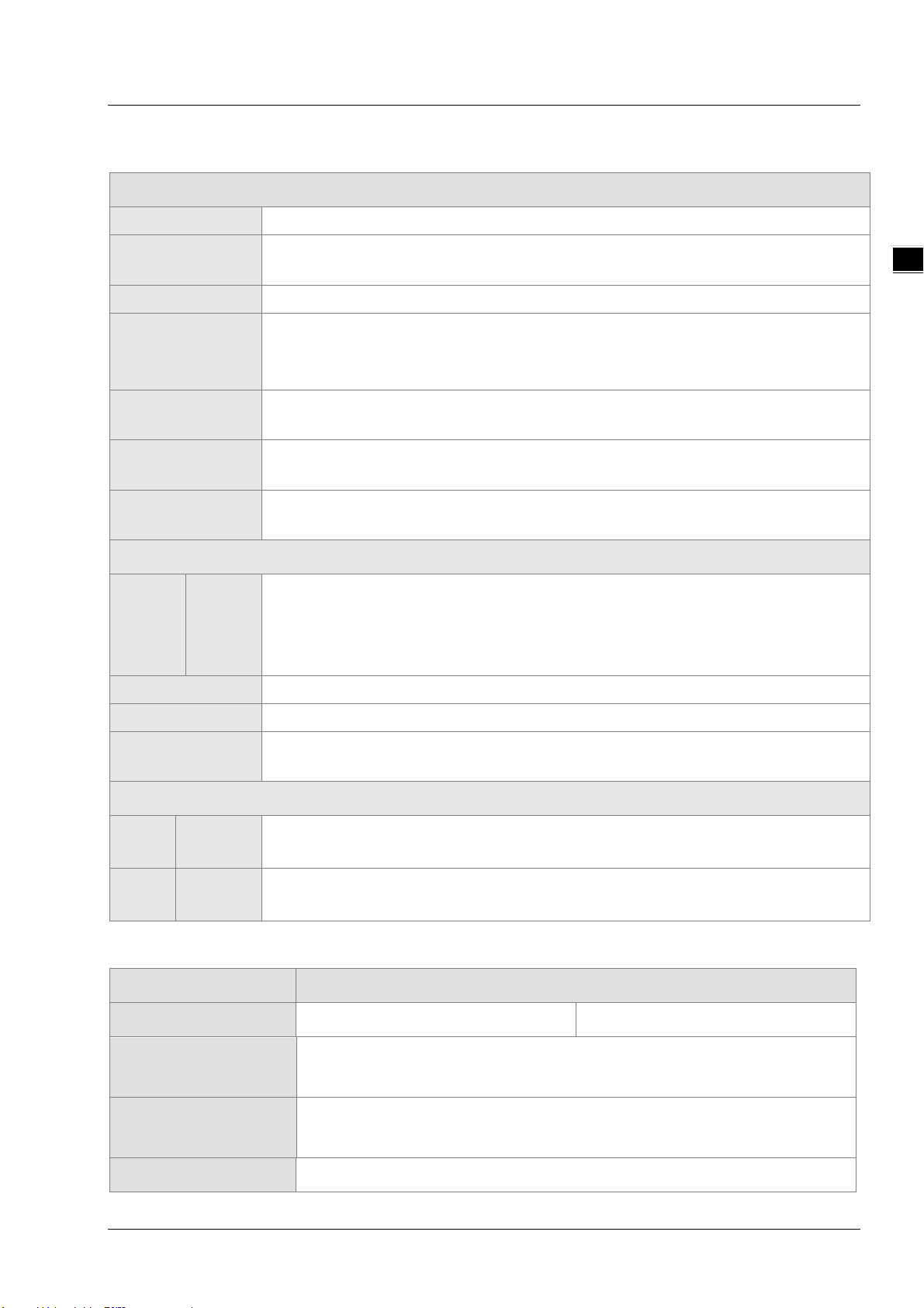
1.1 Specification
Supply voltage 24VDC
Chapter 1 Introduction
DVP02TK-S/DVP02TU-S
Max. rated power
consumption
Connector Type European standard removable terminal block (Pin pitch: 3.5mm)
Operation/storage
temperature
Vibration/Shock
resistance
Connection to
DVP-PLC
I/O points
Input
Hardware Resolution 16 bits
CH1,
CH2
2.4W, supplied by external power source in compliance with UL61010-2-201 \ IEC61131-2
Operation: 0°C ~ 55°C (temperature), 5 ~ 95% (humidity), Pollution degree: 2
Storage: -25°C ~ 70°C (temperature), 5 ~ 95% (humidity), Attitude: up to 2000m;
For use in dry location only
International standards: IEC 61131-2, IEC 68-2-6 (TEST Fc) / IEC 61131-2 & IEC 68-2-27 (TEST
Ea)
The modules are numbered from 0 to 7 automatically by their distance from DVP-PLC. Max. 8
modules are allowed to connect to DVP-PLC and will not occupy any digital I/O points.
2 points of universals analog inputs (CH1, CH2), 2 analog outputs (OUT1, OUT2) or 4 digital
outputs (OUT1~OUT4)
General Analog Input
Thermal resistance: Pt100, JPt100, Pt1000, Ni100, Ni1000, Cu50, Cu100, GNi1000
Thermocouple : J, K, R, S, T, E, N, B, U, L, TXK (L), C, PL II
Voltage input: 0~+50mV, 0~+5V, 0~+10V
Current input: 0mA~+20mA, 4~+20 mA
1
Distance 100 meters
Input disconnection
detection
Analog
Digital
A/D Function Specification
Analog / Digital Voltage Input
Maximum rated input 0V~10V 0V~5V
Overall accuracy
(normal temperature)
Overall accuracy
(full temperature range)
OUT1~
OUT2
OUT1~
OUT4
Supported by exceeded temperature input range
Analog / Digital Output
Analog output, 12-bit: 0~+10V, 0/4~+20mA
4 channels digital output, 250VAC, 60Hz/24VDC, 2A, Relay
4 channels digital output, Voltage pulse output, 24VDC, 300mA
0.5%
1%
Hardware resolution 16 bits
1-3
Page 6
DVP02TK-S/DVP02TU-S Temperature Control Module Manual
_1
Input impedance 650KΩ
Analog / Digital Current Input
Maximum rated input 0mA~20mA 4mA~20mA
Overall accuracy
(normal temperature)
Overall accuracy
(full temperature range)
Hardware resolution 16 bits
Input impedance 249Ω
Analog / Digital Temperature Input
Maximum rated input Thermocouple Thermistor
Overall accuracy
(normal temperature)
Overall accuracy
(full temperature range)
Hardware resolution 24 bits
Input impedance 2MΩ
Analog sampling time (by channel)
0.5%
1%
0.4%
0.8%
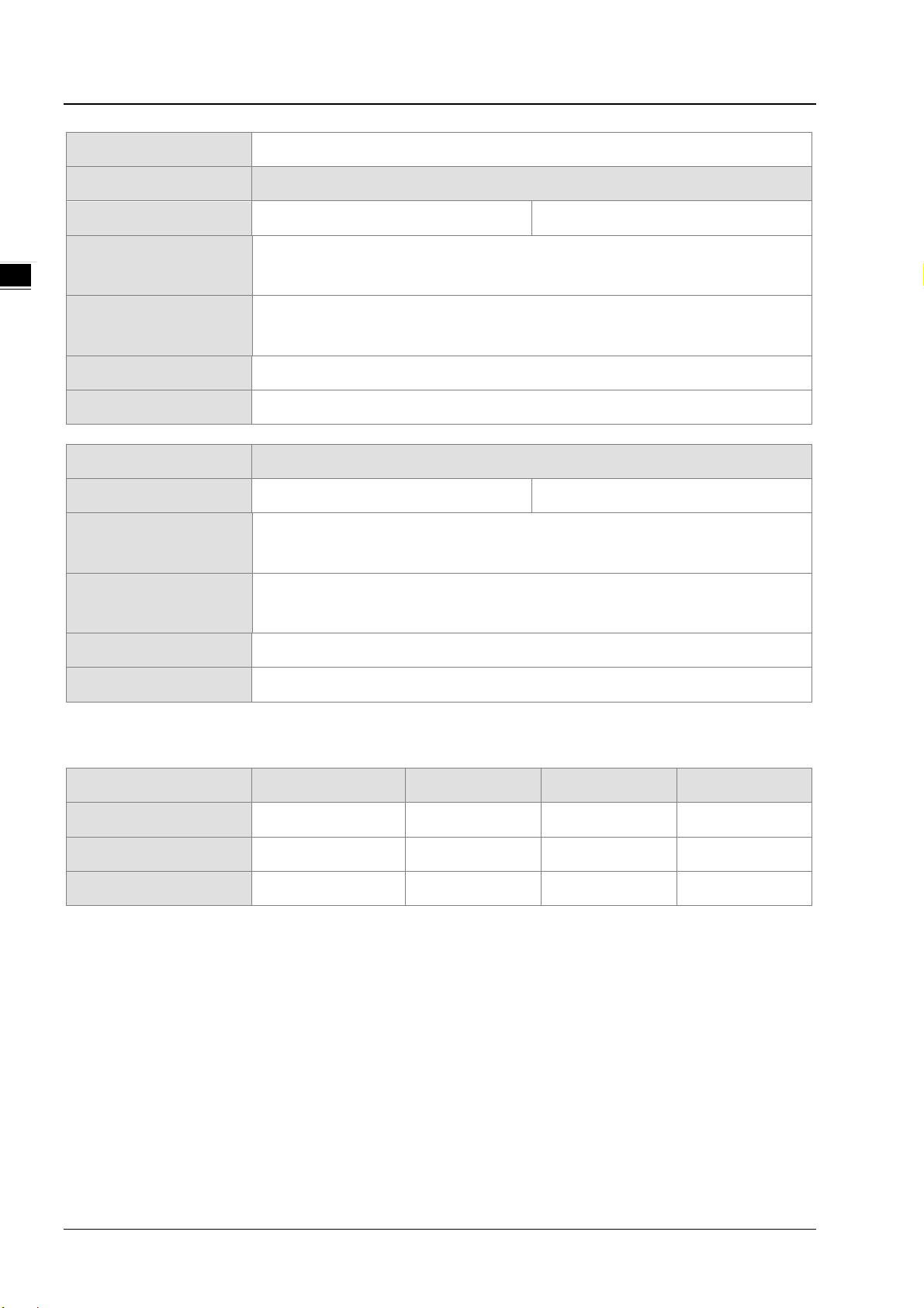
Analog input type AI Thermocouple Thermistor Quick AI (0~10V)*2
Setting time (ms)
Conversion time (ms)
Response time (ms)
Response time = setting time + conversion time
*1. Compared to the response time of the thermocouple temperature, it needs two times of time for the thermistor
temperature to respond, since the thermistor channels require a temperature compensation.
*2. Since there is only one channel used, the time to stabilize the circuit is not required.
80 80 160 3
50 50 100 2
130 130 260 5
1-4
Page 7

_
DVP02TKL-S/DVP02TUL-S D/A Function Specification
Analog / Digital Voltage Output
Maximum rated input 0V~10V
Chapter 1 Introduction
Overall accuracy
0.5%
(normal temperature)
Overall accuracy
1%
(full temperature range)
Hardware resolution 12 bits
Allowable load impedance 1kΩ ~ 2MΩ at 0V~10V
Analog / Digital Current Output
Maximum rated output 0mA~20mA 4mA~20mA
Overall accuracy
0.5%
(normal temperature)
Overall accuracy
(full temperature range)
1%
(average number of 100
times)
Hardware resolution 12 bits
1
Allowable load impedance
Analog setup time (by channel)
Analog output type
Setting time (µs)
Conversion time (µs)
Response time (µs)
Response time = setting time + conversion time
≦550Ω
Voltage Current
100 250
500 500
600 750
1-5
Page 8
DVP02TK-S/DVP02TU-S Temperature Control Module Manual
_1
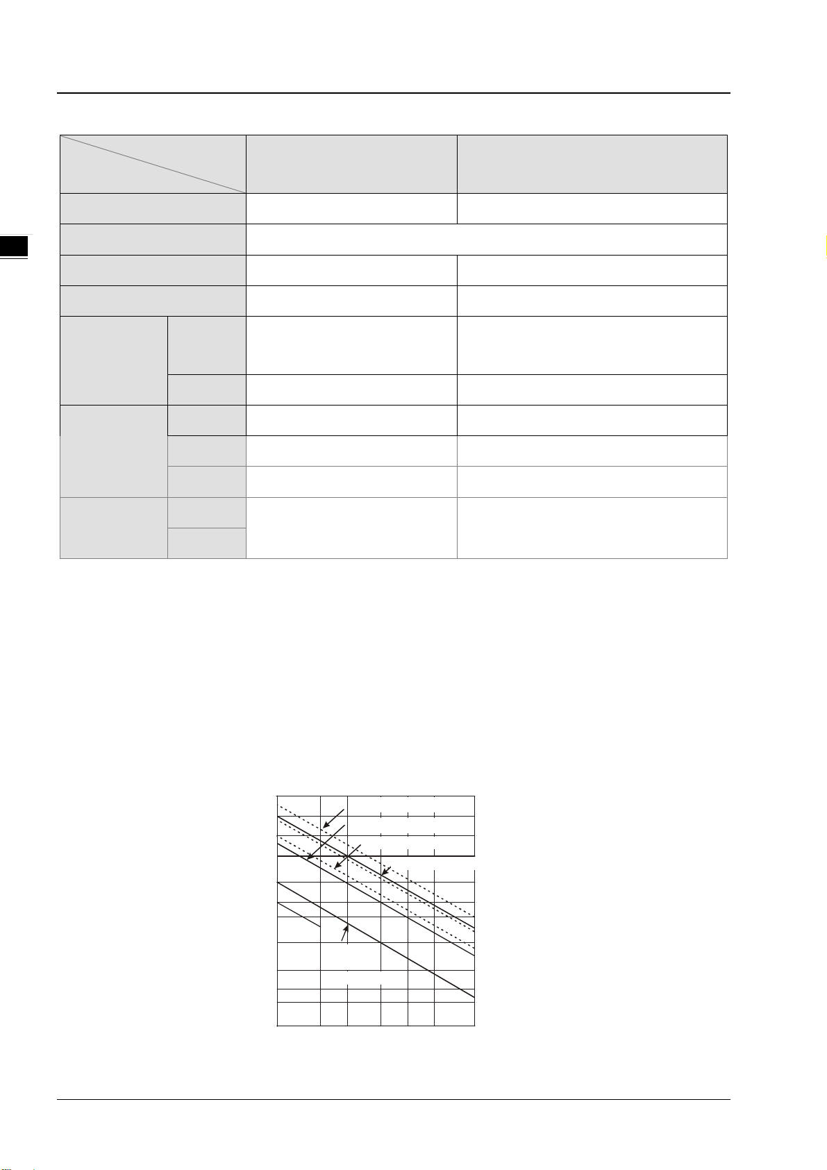
DVP02TKR-S/DVP02TUR-S/DVP02TKN-S/DVP02TUN-S DO Function Specification
Item
Model
DVP02TKR-S
DVP02TUR-S
DVP02TKN-S
DVP02TUN-S
Output points 4 4
Connector Type Removable terminal block
Output point type
Voltage specification
Maximum load
Below 250VAC, 30VDC 12~30VDC
Resistive
Inductive Life curves
Relay-R Transistor-T (NPN)
2A/1point
(3A/COM)
*1
*2, 4
7.2W (24VDC)
0.3A/1 point
(0.6A/COM)
Resistive 1Hz 100Hz
Maximum output
Inductive 0.5Hz 0.5Hz
frequency
Lamp 1Hz 10Hz
Maximum
OFF→ON
10ms 0.5ms
response time
*1
. Complied with UL61010-2-201 & IEC61131-2(AC or DC resistance)
*2
. Complied with UL61010-2-201 & IEC61131-2 (AC/DC general-use or AC pilot duty)
ON→OFF
*1
*3
Rated making capacity: 7.5A; rated breaking capacity: 0.75A; 2.5A thermal continuous at 240VAC
DC pilot duty; rated making capacity: 0.22A; rated breaking capacity: 0.22A; 1A thermal continuous at 30VDC
*3
. Complied with IEC/UL61010-2-201 (DC general-use)
*4
. Life curves
Disconnect power before servicing to avoid the risk of electric shock.
Utilisez relay est sous tension. Risque de choc électrique, couper le courant avant l’entretien.
120VAC Resi stive
30VDC Inductive(t=7ms)
240VAC I nd uct i ve(cos 0.4)
120VAC Ind uct i ve( cos =0.4 )
30VDC
Inductive
(t=40ms)
ψ
=
ψ
3
)
0
1
X
(
n
o
i
t
a
r
e
p
O
3000
2000
1000
500
300
200
100
50
30
20
0.1
0.2
0.5
0.3 0.7 1 2
Contact Current(A)
1-6
Page 9

_
1.2 Dimensions (mm)
1.2.1 DVP02TU-S
Chapter 1 Introduction
25.20
3.00
1
3
90.00
2
DVP-02TU
4
3.00
1 Run/Error indicator
2 Model name
60.00
3.00
3.40
1
6
7
8
5
Description
60.00
3 Removable terminal block
4 I/O terminal layout
5 I/O module clip
6 I/O module connection port
7 Label
8 DIN rail clip
1-7
Page 10

DVP02TK-S/DVP02TU-S Temperature Control Module Manual
_1
1.2.2 DVP02TK-S
25.20
3.00
1
3
90.00
2
4
5
3.00
1 Run/Error indicator
2 Model name
3 Removable terminal block
4 I/O terminal layout
60.00
3.00
6
7
8
9
Description
3.40
60.00
10
11
5 Run/Stop switch
6 I/O module clip
7 I/O module connection port
8 Label
9 DIN rail clip
10 Power connection port
11 RS-485 communication port
1-8
Page 11
Chapter 1 Introduction
_
2TU-S
.
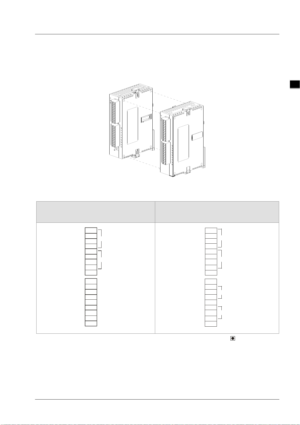
1.3 Installation
Users can connect DVP02TU-S series modules to the right side of the DVP02TK-S series modules as the image sho wn
below. Up to DVP02TU-S can be connected.
DVP02 TK- S
1
1.4 Terminal arrangement
DVP02TKR-S/DVP02TKN-S
DVP02TUR-S/DVP02TUN-S
L+
I+
CH1
L-
I-
L+
I+
CH2
L-
I-
SLD
.
OUT1
OUT2
C0
.
OUT3
OUT4
C1
.
DVP0
DVP02TKL-S/DVP02TUL-S
L+
I+
CH1
L-
I-
L+
I+
CH2
L-
I-
SLD
.
VO
IO
OUT1
AG
.
VO
IO
OUT2
AG
Warning: DO NOT connect wires to the terminals with No Connection (marked by a dot symbol ).
1-9
Page 12
DVP02TK-S/DVP02TU-S Temperature Control Module Manual
_1
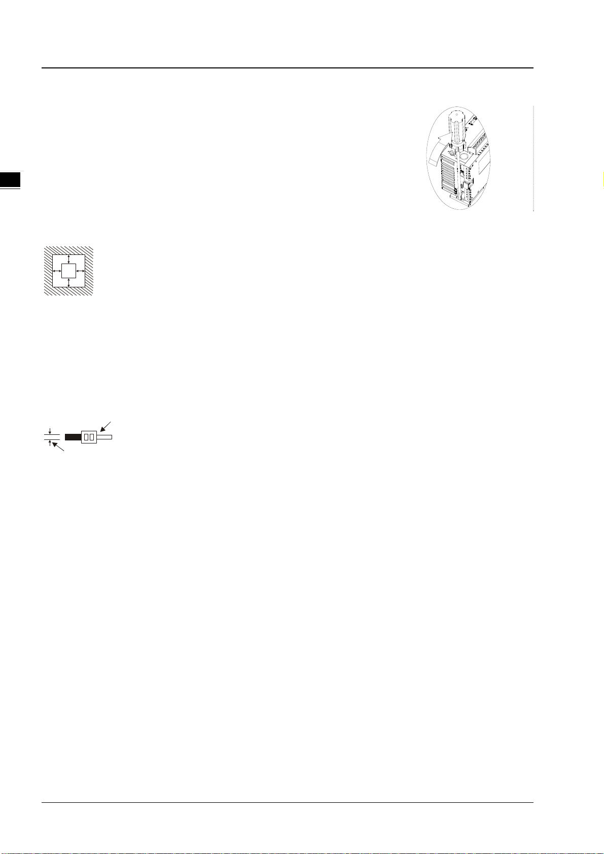
Mounting Arrangements and Wiring Notes
How to install DIN rail
DVP-PLC can be secured to a cabinet by using the DIN rail of 35mm in height and
7.5mm in depth. When mounting PLC to DIN rail, be sure to use the end bracket to
stop any side-to-side movement of PLC and reduce the chance of wires being
loosen. A small retaining clip is at the bottom of PLC. To secure PLC to DIN rail,
place the clip onto the rail and gently push it up. To remove it, pull the retaining clip
down and gently remove PLC from DIN rail, as shown in the figure.
Please install PLC in an enclosure with sufficient space around it to allow heat dissipation as shown in the figure.
D
DD
DVP
MP
D
D > 50 mm
Warning: shock hazard. Only for mounting in a rack or enclosure fully enclosing all live parts.
Avertissement : risque d’électrocution. Ne doit être installé que dans un bâti ou un boîtier recouvrant entièrement toutes
les pièces sous tension.
1.5 Wiring Diagram
22-16AWG
<1.5mm
1. Use 22-16AWG (1.5mm) single or multiple core wire on I/O wiring terminals. The specification of the terminal is
shown in the figure above. The PLC terminal screws shall be tightened to 1.95 kg-cm (1.7 in-lbs).
2. DO NOT place the I/O signal wires and power supply wire in the same wiring duct.
3. Warning: use conductors with insulation rated for at least 75 °c
Avertissement : employer des conducteurs pour au moins 75 °c.
4. For use with copper conductors only (excluding thermocouplers).
destiné à être utilisé avec des conducteurs en cuivre seulement (sauf thermocouples).
1-10
Page 13

_
Sensor input wiring
Ni100/Ni1000/
LG-Ni1000/Cu50/Cu100
Pt10 0 /JPt100 /P t1000
2-Wire
Shielded
cable*1
CH1
L+
I+
L-
I-
SLD
AG
Chapter 1 Introduction
CurrentOutput
ADC
INA
1
Pt100/JPt100
/Pt1000
3-Wire
Shielded
cable*1
Voltage/Current input wiring
0mV~50mV,
0V~+5V,
0V~+10V
+
-
0mA~+20mA,
4mA~+20mA
+
-
Sh ielded
cabl e*1
CH2
CH 1
CH2
L+
I+
L-
I-
SLD
L+
I+
L-
I-
SL D
L+
I+
L-
I-
SL D
AG
Current Output
ADC
INA
AG
AG
1-11
Page 14

DVP02TK-S/DVP02TU-S Temperature Control Module Manual
_1
Thermocouple input wiring
Thermocouple
+
-
DVP02TKN-S/DVP02TUN-S Output point wiring
D
24VDC
+
D: 1N4001
Diode or equivalent com ponent
D
24VDC
+
D: 1N4001
Diode or equivalent com ponent
OUT1
OUT 2
C0
OUT3
OUT4
C1
L+
I+
L-
I-
SLD
Current Output
ADC
INA
AG
DVP02TKR-S/DVP02TUR-S Output point wiring
240V AC
OUT3
OUT4
C1
24V DC
OUT3
OUT4
C1
1-12
Page 15

_
DVP02TKL-S/DVP02TUL-S Output point wiring
e
c
e
*
c
e
*
Chapter 1 Introduction
0V~+10V
0mA ~+2 0m A,
4mA ~+20mA
RS-485 Wiring
Term inal
impedaan ce
(120 ohm)
OUT1
VO
IO
AG
OUT2
VO
IO
AG
Mast
D+ D- SG D+ D- SG SG D+ D-
r Sl ave S lave
AG
AG
CH1
1
CH2
Shielded
abl
1
Shielded
abl
1
1.6 LED Indicator Description
LED Indicator LED Color Description
POWER Green Power status
A/D Green Operating status
ERROR Red Error display
OUT1~OUT4 Red Output status
1.7 RS-485 Communication for DVP02TK-S Series
Data Transmission
Speed
Communication
Format
Communication
Protocool
Stop bit: 1, 2 Parity bit: None, Odd, Even Data bit: 7, 8
9,600; 19,200; 38,400; 57,600; 115,200bps
MODBUS ASCII/RTU
1-13
Page 16

2
Chapter 2 Control Register
Table of Contents
2.1 Control Registers ...................................................................... 2-2
2.1.1 MODBUS Address List for DVP02TK-S Series ................................ 2-2
2.1.2 MODBUS Hex Address List for DVP02TK-S Series .......................... 2-2
2.1.3 List of the Control Registers ....................................................... 2-3
2.1.4 Basic Setup Page ...................................................................... 2-5
2.1.5 PID Setup Page ........................................................................ 2-9
2.1.6 Program Control Setup Page .................................................... 2-11
2.1.7 Pattern0, 1 Setup Page ........................................................... 2-12
2.1.8 Pattern2, 3 Setup Page ........................................................... 2-13
2.1.9 Pattern4, 5 Setup Page ........................................................... 2-15
2.1.10 Pattern6, 7 Setup Page ......................................................... 2-16
2.2 Analog Input Description ........................................................ 2-17
2.3 Outputs .................................................................................. 2-19
2.3.1 The output value varies with the PV value. ................................. 2-19
2.3.2 Alarm Outputs ....................................................................... 2-19
2.4 ON/OFF Control Mode ............................................................. 2-21
2.5 PID Control Mode ................................................................... 2-22
2.6 Programmable SV Control Mode ............................................. 2-24
2.7 ERROR LED Indicator .............................................................. 2-25
2.8 RS-485 Communication Setup for DVP02TK-S ........................ 2-25
2.8.1 MODBUS Communication Protocol ............................................. 2-25
2.8.2 Restore to Factory Settings ...................................................... 2-25
2.8.3 RS-485 Communication Setup .................................................. 2-25
2.9 TK Wizard – Connection Setup ................................................ 2-28
2.9.1 Restore to Factory Settings for DVP02TK-S ................................ 2-28
2.9.2 COMMGR Set Up .................................................................... 2-28
2.9.3 Settings in TKSoft .................................................................. 2-28
2.9.4 TKSoft – Scan the Connected Devices ....................................... 2-29
2-1
Page 17

DVP02TK-S/DVP02TU-S Temper ature Control Module Manual
_2
Number of connected
Detecting number of the extension modules
Code of the 1st module on the right side of
Code of the 2nd module on the right side of
Code of the 4th module on the right side of
Code of the 5th module on the right side of
Code of the 6th module on the right side of
TK series
Code of the 7th module on the right side of
Code of the 8th module on the right side of
TK series
Refer to sections for setting up the RS -485
2.1 Control Registers
2.1.1 MODBUS Address List for DVP02TK-S Series
MODBUS Address Description
H0000 TK series, CR#0: starting address
H1000 The 1st module on the right side of TK series, CR#0: starting address
H2000 The 2nd module on the right side of TK series, CR#0: starting address
H3000 The 3rd module on the right side of TK series, CR#0: starting addr es s
H4000
H5000
H6000
H7000
H8000
th
module on the right side of TK series, CR#0: starting addr es s
The 4
th
module on the right side of TK series, CR#0: starting addr es s
The 5
th
module on the right side of TK series, CR#0: starting addr es s
The 6
th
module on the right side of TK series, CR#0: starting addr es s
The 7
th
module on the right side of TK series, CR#0: starting addr es s
The 8
2.1.2 MODBUS Hex Address List for DVP02TK-S Series
Address
(Hex)
0F00 R X
0F01 R X Code of the 1
0F02 R X Code of the 2nd module
0F03 R X Code of the 3rd module
0F04 R X Code of the 4th module
Attribute Name Description Default
extension modules
st
module
connected to the right side of the TK s eries
TK series
TK series
Code of the 3rd module on the right side of
TK series
TK series
--
--
--
--
--
0F05 R X
0F06 R X
0F07 R X
0F08 R X
0F09 R/W O RS-485 c om munication setup
0F0A R/W X Reserved
0F0B R/W O RS-485 communic ation format
0F0C R/W O TK station number TK station number setup K1
0F0D R/W X TK operation
2-2
Code of the 5th module
Code of the 6th module
Code of the 7th module
Code of the 8th module
TK series
TK series
communication mode
0:ASCII / 1:RTU
0:Stop / 1:Run
--
--
--
--
K0
K0
--
Page 18

2_
2.1.3 List of the Control Registers
setups to
CH2 setups to
Setups to switch
Chapter 2 Control Register
TU
CR#
#0
#1
#2
#3
#4
#5
#6
#7
#8
#9
#10
TK
Add.
(Hex)
009
00A
Attribute Name Description Default
000
001
002
003
004
005
006
007
008
R O Model
R O Firmware version
R O CH1 PV
R O CH2 PV
R/W O CH1 SV setups
R/W O CH2 SV setups
R/W X
R/W X
R/W X CH1 Auto tuning
R/W X CH2 Auto tuning
R/W X
CH1
run/stop an operation
run/stop an operation
pages
By default, users can see the model name in the
program and determine whether there is any
extension module.
DVP02TUL-S: H014F
DVP02TUN-S: H024F
DVP02TUR-S: H034F
DVP02TKL-S: H044F
DVP02TKN-S: H054F
DVP02TKR-S: H064F
Hexadecimal, displaying the curr ent firmware
version, for example the current firmware is 1.02 and
it will display H’0102.
Channel current value --
Channel target value K0
K0: stop
K1: run
K2: pause (programmable)
K0: Auto control mode
K1: Auto adjust mode, after adjusting it will switch to
the auto control mode and input the most suitable
parameters, e.g., Kc_Kp, Ti_Ki, Td_Kd and Tf.
CR#11~CR#42: Definitions may vary according to
different setups on the specifi c page.
K0: Basic setup page for CH1
K1: PID setup page for CH1
K2: Program control setup page for CH1
K3: Pattern 0, 1 setup page for CH1
K4: Pattern 2, 3 setup page for CH1
K5: Pattern 4, 5 setup page for CH1
K6: Pattern 6, 7 setup page for CH1
K10: Basic setup page for CH2
K11: PID setup page for CH2
K12: Program control setup page for CH2
K13: Pattern 0, 1 setup page for CH2
K14: Pattern 2, 3 setup page for CH2
K15: Pattern 4, 5 setup page for CH2
--
--
K0
K0
K0
2-3
Page 19

DVP02TK-S/DVP02TU-S Temperature Control Module Manual
_2
According to each
TU
CR#
#11~
#42
--
--
--
--
--
--
--
--
--
--
--
--
--
--
#43
#45
TK
Add.
(Hex)
--
00B
02B
04B
06B
08B
0AB
0CB
0EB
10B
12B
14B
16B
18B
1AB
24B
24D
Attribute Name Description Default
K16: Pattern 6, 7 setup page for CH2
R/W X
R/W -- Page0 Basic setup page for CH1 --
R/W -- Page1 PID setup page for CH1 --
R/W -- Page2 Program control setup page for CH1 --
R/W O Page3 Pattern 0, 1 setup page for CH1 --
R/W O Page4 Pattern 2, 3 setup page for CH1 --
R/W O Page5 Pattern 4, 5 setup page for CH1 --
R/W O Page6 Pattern 6, 7 setup page for CH1 --
R/W O Page10 Basic setup page for CH2 --
R/W O Page11 PID setup page for CH2 --
R/W O Page12 Program control setup page for CH2 --
R/W O Page13 Pattern 0, 1 setup page for CH2 --
R/W O Page14 Pattern 2, 3 setup page for CH2 --
R/W O Page15 Pattern 4, 5 setup page for CH2 --
R/W O Page16 Pattern 6, 7 setup page for CH2 --
X Error code Please refer to error code descriptions. K0
R/W X User-defined
setup page
Please refer to each setup page. K0
0x0501: Restore to defaults
0x0502: Settings written on flash
0x0504: RS-485 mode and latched
(parameter/mode/station number)
0x51CC: Manually export
0x51DD:Auto export
(the PID will be invalid after switc hing to manually
export mode.)
CR control can be set up by the analog output of
DVP02TUL-S/DVP02TKL-S and the digital output of
/DVP02TUN-S/DVP02TKR-S/DVP02TKN-S.
DVP02TUL-S/DVP02TKL-S:
K0
#46
#47
Symbols: O: Latched. X: Non-latched.
2-4
24E
24F
CR#4: CH1 analog output value range K0~K4000
CR#5: CH2 analog output value range K0~K4000
DVP02TUR-S/DVP02TUN-S/DVP02TKR-S/DVP02
TKN-S:
CR#4 (bit0/bit1): CH1 digital output Y0/Y1
CR#5 (bit0/bit1): CH2 digital output Y2/Y3
R O CH1 display value
R O CH2 display value
The display value is the measured value after being
rounded off or the value set to be displayed for the
channels.
Page 20

Chapter 2 Control Register
2_
TU
CR#
R: Able to read data by FROM instruct ion. W: Able to write data by TO instruc tion.
TK
Add.
(Hex)
Bit0 Power Supply abnormal Abnormal Normal
Bit1 Hardware abnormal Abnormal Normal
Bit2 CH1 conversion error Abnormal Normal
Bit3 CH2 conversion error Abnormal Normal
Bit4 CH1 circuit control abnormal Abnormal Normal
Bit5 CH2 circuit control abnormal Abnormal Normal
Bit6 Manually / Auto Output Manually Output Auto Output
Bit7-15 Reserved
Attribute Name Description Default
Error Code 1 0
2.1.4 Basic Setup Page
TU
CR#
#11
TK CH1
Page0
Add. (Hex)
00B 0EB
TK CH2
Page10
Add. (Hex)
Attribute Name Description Default
K-1: Channel closed
K0: 0 ~ 5V
K1: 0~10V
K2: 0 ~ 20mA
K3: 4 ~ 20mA
K4: 0 ~ 50mV
K5: Pt100
K6: JPt100
K7: Pt1000
K8: J
R/W O Sensor type
K9: K
K10: R
K11: S
K12: T
K13: E
K14: N
K15: B
K16: L
K17: U
K18: TXK
K19: C
K20: PL II
K0
2-5
Page 21

DVP02TK-S/DVP02TU-S Temperature Control Module Manual
_2
Temperature filter ranging
10 of the last inputted
value, the system will run the
Output 2
TU
CR#
#12
#13
#14
#15
#16
#17
#18
TK CH1
Page0
Add. (Hex)
00C 0EC
00D 0ED
00E 0EE
00F 0EF
010 0F0
011 0F1
012 0F2
TK CH2
Page10
Add. (Hex)
Attribute Name Description Default
K21: Cu50
K22: Cu100
K23: Ni100
K24: Ni1000
K25: LGNi1000
K26: 0~10V (Quick AI)
O
K0:
R/W O
R/W O
R/W O
R/W O Filtering factor
R/W O Control type
R/W O Output 1 control
R/W O
Unit of
temperature
Offset
temperature
error
Temperature
filter range
C
O
K1:
F
K-999 ~ K999 K0
10~10000
When the value inputted is in the
range of ±
filtering measurement. Hence, when
the noise interference is bigger, the
filter range should set to bigger too.
Ranging 0~50.
Operational formula: value = (last
value*n + this measurement ) / (n+1)
When the set value is less, the PV
will be closer to this measurement.
When the set value is bigger, the
filtering factor will be bigger and the
PV will be similar.
K0: PID Auto
K1: PID Manual
K2: PID program control
K3: ON/OFF
(for DVP02TUR-S/DVP02TUN-S/
DVP02TKR-S/DVP02TKN-S)
K0: Heating
K1: Cooling
K2: Alarm
(for DVP02TUR-S /DVP02TUN-S/
DVP02TKR-S /DVP02TKN-S)
K3: Proportion (for DVP02TUL-S/
DVP02TKL-S)
K0: Heating K0
K10
K0
K1
K0
K0
2-6
Page 22

Chapter 2 Control Register
2_
and when the reading is 1000, the
TU
CR#
#21
#23
#24
#25 R/W O Alarm 1 output
#26 R/W O Alarm 2 output K0
#27
#28
#29
#30
#32
#33
TK CH1
Page0
Add. (Hex)
015 0F5
TK CH2
Page10
Add. (Hex)
Attribute Name Description Default
control K1: Cooling
K2: Alarm
Note: not for DVP02TUL-S/
DVP02TKL-S
K0: cyclic output
K1: immediately output
DVP02TUN-S/ DVP02TKN-S:
R/W O Output setup
Output 1:
R/W O
R/W O
R/W O
R/W O
R/W O
R/W O
R/W O
R/W O
heating/cooling
control cycle
setup
Output 2:
heating/cooling
control cycle
setup
Alarm output 1
upper-limit
setup
Alarm output 1
lower-limit
setup
Alarm output 2
upper-limit
setup
Alarm output 2
lower-limit
setup
PV upper-limit
setup for a
corresponding
output
PV lower-limit
setup for a
corresponding
K0 (default)
DVP02TUR-S/ DVP02TKR-S:
K1 (default)
Note: not available for
DVP02TUL-S/DVP02TKL-S
DVP02TUN-S/ DVP02TKN-S:
1~990 at 0.1 per second, default:
K10.
DVP02TUR-S/ DVP02TKR-S:
30~990 at 0.1 per second (default)
Note: not available for
DVP02TUL-S/DVP02TKL-S.
K0~K12, please refer to the error
code description.
Note: not available for
DVP02TUL-S/DVP02TKL-S.
For DVP02TUL-S series
When the input value varies, the
corresponding output will vary
accordingly. Take 4~20mA as an
example, and set the upper-limit to
1000, lower-limit to 0; when the
reading is 0, the output will be 4mA
K0/K1
K10
K30
K1000
K0
K0
K0
K0
K0
K0
2-7
Page 23

DVP02TK-S/DVP02TU-S Temperature Control Module Manual
_2
TU
CR#
#34
#35
#36
#37
#38
#39
#40
TK CH1
Page0
Add. (Hex)
TK CH2
Page10
Add. (Hex)
Attribute Name Description Default
output output will be 20mA. When set it to
a negative slope, and set the range
to 0~1000; when the reading is 0,
the output will be 20mA and when
the reading is 1000, the output will
be 4mA.
R/W X
R/W O
R/W O
R/W O
R/W O
R/W O
R X Outputting
For system
usage
Heating
hysteresis
setup
Cooling
hysteresis
setup
Analog output
mode
Out of the LED
setting range
Dead band
setup for dual
outputs
X
ON-OFF
(For DVP02TUN-S / DVP02TUR-S
/ DVP02TKN-S / DVP02TKR-S)
For DVP02TUL-S / DVP02TKL-S
K0: 0~10V
K1: 0~20mA
K2: 4~20mA
K0=LED blinking
K1=LED not blinking
Setting range: -32768~32767
Note: not for DVP02TUL-S /
DVP02TKL-S
DVP02TUL-S / DVP02TKL-S:
analog output value 0~4000
DVP02TUN-S/DVP02TUR-S/DVP0
2TKN-S/DVP02TKR-S:
K10
K10
K0
K0
K0
--
Bit0: Digital output point, OUT1
Bit1: Digital output point OUT2
#41
Symbols: O: Latched. X: Non-latched.
R: Able to read data by FROM instruct ion. W: Able to write data by TO instruc tion.
R O
Set up the
display value
for the channel.
If the preset value (PV) is bigger
than the display value, set the PV
to be the same as the display
value, ranging from 0~100.
2-8
K2
Page 24

2_
2.1.5 PID Setup Page
0~100, and the unit is 0.01.
#14-
otherwise the present error will be
Chapter 2 Control Register
TU
CR#
#11
#12
#13
#17
#18 032 112
#19 033 113
#20 034 114
TK CH1
Page1
Add. (Hex)
02B 10B
02C 10C
02D 10D
Reserved
TK CH2
Page11
Add. (Hex)
Attribute Name Description Default
K0:Normal, the value of MOUT
won’t be changed with the value of
R/W O MOUT_AUTO
R/W O MOUT
R/W O α value
R/W O PID_EQ
R/W O PID_DE
R/W O ERR_DBW
MV.
K1:Auto, the value of MOUT will be
changed with the value of MV.
When set to PID Manual, the MV
value will be outputted as the
manually set MOUNT value,
between MV_MAX and MV_MIN.
Adjust the interface setup range
PID formula types
0: Independent Formula
1: Dependent Formula
The calculation of the PID
derivative error
1: Using the variations in the PV t o
calculate the control value of the
derivative (Derivative of the PV) .
0: Using the variations in the error
(E) to calculate the control value of
the derivative (Derivative of the
error).
Error dead bandwidth: Range
within which an error (E) is 0. An
error (E) is equal to SV−PV or
PV-SV. If the setting value is 0, the
function will not be enabled;
otherwise the CPU module will
check whether the present error is
less than the absolute value of
ERR_DBW, and check whether the
present error meets the cross
status condition. If the present error
is less than the absolute value of
ERR_DBW, and meets the cross
status condition, the present error
will be count as 0, and the PID
algorithm will be implemented,
K65
K0
K0
K0
K0
K0
2-9
Page 25

DVP02TK-S/DVP02TU-S Temperature Control Module Manual
_2
PID working:
#26
03A
11A
R/W O β value
K0 ~ K100 and the unit is 0.1%.
K65
TU
CR#
#21 035 115
#22 036 116
#23 037 117
#24 038 118
#25 039 119 R/W O
TK CH1
Page1
Add. (Hex)
TK CH2
Page11
Add. (Hex)
Attribute Name Description Default
R/W O BIAS
R/W X MV
R/W X
R/W X
I_MV(Low
word)
I_MV(High
word)
AUTO Tuning
(PID
hysteresis)
brought into the PID algorithm
according to the normal
processing.
Feedforward output value, used for
the PID feedforward.
The MV output value is 0~K1000
and the unit is 0.1%.
Accumulated integral value
temporarily stored is usually f or
reference. Users can still clear or
modify it according to their needs.
When the MV is greater than the
MV_MAX, or when the MV is less
than MV_MIN, the accumulated
integral value in I_MV is
unchanged.
Accumulated integral value
temporarily stored is usually f or
reference. Users can still clear or
modify it according to their needs.
When the MV is greater than the
MV_MAX, or when the MV is less
than MV_MIN, the accumulated
integral value in I_MV is
unchanged.
SV - PID Range < PV < SV +
PID Range
K0
--
--
--
K8
#27 03B 11B R/W O
#28 03C 11C R/W O
#29 03D 11D R/W O
#30 03E 11E R/W O
#31 03F 11F R/W O
#32 040 120 R/W O
2-10
Kc_Kp floating
point format
(Lo word)
Kc_Kp floating
point format
(Hi word)
Ti_Ki floating
point format
(Lo word)
Ti_Ki floating
point format
(Hi word)
Td_Kd floating
point format
(Lo word)
Td_Kd floating
point format
(Hi word)
Calculated proportional coefficient
(Kc or Kp)
If the P coefficient is less than 0,
the Kc_Kp will be 0. Independentl y,
if Kc_Kp is 0, it will not be
controlled by P.
Integral coefficient (Ti or Ki)
If the calculated coefficient I is l es s
than 0, Ti_Ki will be 0. If Ti_Ki is 0,
it will not be controlled by I.
Derivative coefficient (Td or Kd)
If the calculated coefficient D is less
than 0, Td_Kd will be 0. If Ti_Ki is
0, it will not be controlled by D.
K100
K10
-1
Page 26

Chapter 2 Control Register
2_
Tf floating point
TK CH1
TK CH2
Pattern6_ set up for the
TU
CR#
#33 041 121 R/W O
#34 042 122 R/W O
#35 043 123 R/W O
Symbols: O: Latched. X: Non-latched.
R: Able to read data by FROM instruct ion. W: Able to write data by TO instruction.
TK CH1
Page1
Add. (Hex)
TK CH2
Page11
Add. (Hex)
Attribute Name Description Default
format
(Lo word)
Tf floating point
format
(Hi word)
Default integral
coefficient
Derivate-action time constant (TF)
If the derivate-action time constant
is less than 0, Tf will be 0 and it will
not be controlled by the
derivate-action time constant.
(Derivative Smoothing)
0~10000 K1000
2.1.6 Program Control Setup Page
TU
CR#
#11
#12
#13
#14
#15
#16
#17
#18
#19
#20
#21
#22
#23
Page2
Address
(Hex)
04B 12B
04C 12C
04D 12D
04E 12E
04F 12F
050 130
051 131
052 132
053 133
054 134
055 135
056 136
057 137
Page12
Address
(Hex)
Attribute
R/W O
R/W O
R/W O
R X
R X
R X
R/W O
R/W O
R/W O
R/W O
R/W O
R/W O
R/W O
Name Description Default
Pattern number to start
running
Step number to start
running
The Cycle index of the
Pattern number 0~7 to
repeat running
Read the current running
pattern number
Read the current running
step number
Read the step running
time left
Pattern0_set up for the
max. step number to run
Pattern1_ set up for the
max. step number to run
Pattern2_ set up for the
max. step number to run
Pattern3_ set up for the
max. step number to run
Pattern4_ set up for the
max. step number to run
Pattern5_ set up for the
max. step number to run
0~7 K0
0~7 K0
K0~K99 indicates the running
times of the Pattern has
reached 100
0~8 (8 indicates ending) K0
0~7 K0
Unit (seconds) K0
0~7 K0
0~7 K0
0~7 K0
0~7 K0
0~7 K0
0~7 K0
0~7 K0
1
K0
2-11
Page 27

DVP02TK-S/DVP02TU-S Temperature Control Module Manual
_2
TK CH1
TK CH2
TU
CR#
#24
#25
#26
Page2
Address
(Hex)
058 138
059 139
05A 13A
Page12
Address
(Hex)
Attribute
R/W O
R X
R/W O
max. step number to run
Pattern7_ set up for the
max. step number to run
The current cycle index
number of the Pattern
number 0~7 to repeat
running
Temperature hysteresis
setup
2.1.7 Pattern0, 1 Setup Page
TU
CR#
#11
#12
#13
#14
#15
#16
#17
#18
#19
#20
#21
#22
#23
#24
#25
#26
#27
TK CH1
Page3
Address
(Hex)
06B 14B
06C 14C
06D 14D
06E 14E
06F 14F
070 150
071 151
072 152
073 153
074 154
075 155
076 156
077 157
078 158
079 159
07A 15A
07B 15B
TK CH2
Page13
Address
(Hex)
Attribute
R/W O
R/W O
R/W O
R/W O
R/W O
R/W O
R/W O
R/W O
R/W O
R/W O
R/W O
R/W O
R/W O
R/W O
R/W O
R/W O
R/W O
Pattern0-0 Target temperature Range: -32768~32767
Pattern0-1 Target temperature Range: -32768~32767
Pattern0-2 Target temperature Range: -32768~32767
Pattern0-3 Target temperature Range: -32768~32767
Pattern0-4 Target temperature Range: -32768~32767
Pattern0-5 Target temperature Range: -32768~32767
Pattern0-6 Target temperature Range: -32768~32767
Pattern0-7 Target temperature Range: -32768~32767
Pattern0-0 Running time
Pattern0-1 Running time
Pattern0-2 Running time
Pattern0-3 Running time
Pattern0-4 Running time
Pattern0-5 Running time
Pattern0-6 Running time
Pattern0-7 Running time
Pattern1-0 Target temperature Range: -32768~32767
Name Description Default
0~7 K0
0~7 K0
0~999 (unit: 0.1) K0
Name Description Default
K0
K0
K0
K0
K0
K0
K0
K0
Range: 0~90 Unit
(minutes)
Range: 0~90 Unit
(minutes)
Range: 0~90 Unit
(minutes)
Range: 0~90 Unit
(minutes)
Range: 0~90 Unit
(minutes)
Range: 0~90 Unit
(minutes)
Range: 0~90 Unit
(minutes)
Range: 0~90 Unit
(minutes)
K0
K0
K0
K0
K0
K0
K0
K0
K0
2-12
Page 28

Chapter 2 Control Register
2_
TK CH1
TK CH2
TU
CR#
#28
#29
#30
#31
#32
#33
#34
#35
#36
#37
#38
#39
#40
#41
#42
TK CH1
Page3
Address
(Hex)
07C 15C
07D 15D
07E 15E
07F 15F
080 160
081 161
082 162
083 163
084 164
085 165
086 166
087 167
088 168
089 169
08A 16A
TK CH2
Page13
Address
(Hex)
Attribute
R/W O
R/W O
R/W O
R/W O
R/W O
R/W O
R/W O
R/W O
R/W O
R/W O
R/W O
R/W O
R/W O
R/W O
R/W O
Name Description Default
Pattern1-1 Target temperature Range: -32768~32767
Pattern1-2 Target temperature Range: -32768~32767
Pattern1-3 Target temperature Range: -32768~32767
Pattern1-4 Target temperature Range: -32768~32767
Pattern1-5 Target temperature Range: -32768~32767
Pattern1-6 Target temperature Range: -32768~32767
Pattern1-7 Target temperature Range: -32768~32767
Pattern1-0 Running time
Pattern1-1 Running time
Pattern1-2 Running time
Pattern1-3 Running time
Pattern1-4 Running time
Pattern1-5 Running time
Pattern1-6 Running time
Pattern1-7 Running time
Range: 0~900 Unit
(minutes)
Range: 0~900 Unit
(minutes)
Range: 0~900 Unit
(minutes)
Range: 0~900 Unit
(minutes)
Range: 0~900 Unit
(minutes)
Range: 0~900 Unit
(minutes)
Range: 0~900 Unit
(minutes)
Range: 0~900 Unit
(minutes)
K0
K0
K0
K0
K0
K0
K0
K0
K0
K0
K0
K0
K0
K0
K0
2.1.8 Pattern2, 3 Setup Page
TU
CR#
#11
#12
#13
#14
#15
#16
#17
#18
#19
Page4
Address
(Hex)
08B 16B
08C 16C
08D 16D
08E 16E
08F 16F
090 170
091 171
092 172
093 173
Page14
Address
(Hex)
Attribute
R/W O
R/W O
R/W O
R/W O
R/W O
R/W O
R/W O
R/W O
R/W O
Pattern2-0 Target temperature Range: -32768~32767
Pattern2-1 Target temperature Range: -32768~32767
Pattern2-2 Target temperature Range: -32768~32767
Pattern2-3 Target temperature Range: -32768~32767
Pattern2-4 Target temperature Range: -32768~32767
Pattern2-5 Target temperature Range: -32768~32767
Pattern2-6 Target temperature Range: -32768~32767
Pattern2-7 Target temperature Range: -32768~32767
Pattern2-0 Running time
Name Description Default
K0
K0
K0
K0
K0
K0
K0
K0
Range: 0~90 Unit
(minutes)
K0
2-13
Page 29

DVP02TK-S/DVP02TU-S Temperature Control Module Manual
_2
TK CH1
TK CH2
TU
CR#
#20
#21
#22
#23
#24
#25
#26
#27
#28
#29
#30
#31
#32
#33
#34
#35
#36
#37
#38
#39
#40
#41
#42
Page4
Address
(Hex)
094 174
095 175
096 176
097 177
098 178
099 179
09A 17A
09B 17B
09C 17C
09D 17D
09E 17E
09F 17F
0A0 180
0A1 181
0A2 182
0A3 183
0A4 184
0A5 185
0A6 186
0A7 187
0A8 188
0A9 189
0AA 18A
Page14
Address
(Hex)
Attribute
R/W O
R/W O
R/W O
R/W O
R/W O
R/W O
R/W O
R/W O
R/W O
R/W O
R/W O
R/W O
R/W O
R/W O
R/W O
R/W O
R/W O
R/W O
R/W O
R/W O
R/W O
R/W O
R/W O
Name Description Default
Pattern2-1 Running time
Pattern2-2 Running time
Pattern2-3 Running time
Pattern2-4 Running time
Pattern2-5 Running time
Pattern2-6 Running time
Pattern2-7 Running time
Pattern3-0 Target temperature Range: -32768~32767
Pattern3-1 Target temperature Range: -32768~32767
Pattern3-2 Target temperature Range: -32768~32767
Pattern3-3 Target temperature Range: -32768~32767
Pattern3-4 Target temperature Range: -32768~32767
Pattern3-5 Target temperature Range: -32768~32767
Pattern3-6 Target temperature Range: -32768~32767
Pattern3-7 Target temperature Range: -32768~32767
Pattern3-0 Running time
Pattern3-1 Running time
Pattern3-2 Running time
Pattern3-3 Running time
Pattern3-4 Running time
Pattern3-5 Running time
Pattern3-6 Running time
Pattern3-7 Running time
Range: 0~90 Unit
(minutes)
Range: 0~90 Unit
(minutes)
Range: 0~90 Unit
(minutes)
Range: 0~90 Unit
(minutes)
Range: 0~90 Unit
(minutes)
Range: 0~90 Unit
(minutes)
Range: 0~90 Unit
(minutes)
Range: 0~900 Unit
(minutes)
Range: 0~900 Unit
(minutes)
Range: 0~900 Unit
(minutes)
Range: 0~900 Unit
(minutes)
Range: 0~900 Unit
(minutes)
Range: 0~900 Unit
(minutes)
Range: 0~900 Unit
(minutes)
Range: 0~900 Unit
(minutes)
K0
K0
K0
K0
K0
K0
K0
K0
K0
K0
K0
K0
K0
K0
K0
K0
K0
K0
K0
K0
K0
K0
K0
2-14
Page 30

2_
2.1.9 Pattern4, 5 Setup Page
TK CH1
TK CH2
Chapter 2 Control Register
TU
CR#
#11
#12
#13
#14
#15
#16
#17
#18
#19
#20
#21
#22
#23
#24
#25
#26
#27
#28
#29
#30
#31
#32
#33
#34
#35
#36
#37
Page5
Address
(Hex)
0AB 18B
0AC 18C
0AD 18D
0AE 18E
0AF 18F
0B0 190
0B1 191
0B2 192
0B3 193
0B4 194
0B5 195
0B6 196
0B7 197
0B8 198
0B9 199
0BA 19A
0BB 19B
0BC 19C
0BD 19D
0BE 19E
0BF 19F
0C0 1A0
0C1 1A1
0C2 1A2
0C3 1A3
0C4 1A4
0C5 1A5
Page15
Address
(Hex)
Attribute
R/W O
R/W O
R/W O
R/W O
R/W O
R/W O
R/W O
R/W O
R/W O
R/W O
R/W O
R/W O
R/W O
R/W O
R/W O
R/W O
R/W O
R/W O
R/W O
R/W O
R/W O
R/W O
R/W O
R/W O
R/W O
R/W O
R/W O
Name Description Default
Pattern4-0 Target temperature Range: -32768~32767
Pattern4-1 Target temperature Range: -32768~32767
Pattern4-2 Target temperature Range: -32768~32767
Pattern4-3 Target temperature Range: -32768~32767
Pattern4-4 Target temperature Range: -32768~32767
Pattern4-5 Target temperature Range: -32768~32767
Pattern4-6 Target temperature Range: -32768~32767
Pattern4-7 Target temperature Range: -32768~32767
Pattern4-0 Running time
Pattern4-1 Running time
Pattern4-2 Running time
Pattern4-3 Running time
Pattern4-4 Running time
Pattern4-5 Running time
Pattern4-6 Running time
Pattern4-7 Running time
Pattern5-0 Target temperature Range: -32768~32767
Pattern5-1 Target temperature Range: -32768~32767
Pattern5-2 Target temperature Range: -32768~32767
Pattern5-3 Target temperature Range: -32768~32767
Pattern5-4 Target temperature Range: -32768~32767
Pattern5-5 Target temperature Range: -32768~32767
Pattern5-6 Target temperature Range: -32768~32767
Pattern5-7 Target temperature Range: -32768~32767
Pattern5-0 Running time
Pattern5-1 Running time
Pattern5-2 Running time
Range: 0~90 Unit
(minutes)
Range: 0~90 Unit
(minutes)
Range: 0~90 Unit
(minutes)
Range: 0~90 Unit
(minutes)
Range: 0~90 Unit
(minutes)
Range: 0~90 Unit
(minutes)
Range: 0~90 Unit
(minutes)
Range: 0~90 Unit
(minutes)
Range: 0~900 Unit
(minutes)
Range: 0~900 Unit
(minutes)
Range: 0~90 Unit
(minutes)
K0
K0
K0
K0
K0
K0
K0
K0
K0
K0
K0
K0
K0
K0
K0
K0
K0
K0
K0
K0
K0
K0
K0
K0
K0
K0
K0
2-15
Page 31

DVP02TK-S/DVP02TU-S Temperature Control Module Manual
_2
TK CH1
TK CH2
TU
CR#
#38
#39
#40
#41
#42
Page5
Address
(Hex)
0C6 1A6
0C7 1A7
0C8 1A8
0C9 1A9
0CA 1AA
Page15
Address
(Hex)
Attribute
R/W O
R/W O
R/W O
R/W O
R/W O
Pattern5-3 Running time
Pattern5-4 Running time
Pattern5-5 Running time
Pattern5-6 Running time
Pattern5-7 Running time
2.1.10 Pattern6, 7 Setup Page
TU
CR#
#11
#12
#13
#14
#15
#16
#17
#18
#19
#20
#21
#22
#23
#24
#25
#26
TK CH1
Page6
Address
(Hex)
0CB 1AB
0CC 1AC
0CD 1AD
0CE 1AE
0CF 1AF
0D0 1B0
0D1 1B1
0D2 1B2
0D3 1B3
0D4 1B4
0D5 1B5
0D6 1B6
0D7 1B7
0D8 1B8
0D9 1B9
0DA 1BA
TK CH2
Page16
Address
(Hex)
Attribute
R/W O
R/W O
R/W O
R/W O
R/W O
R/W O
R/W O
R/W O
R/W O
R/W O
R/W O
R/W O
R/W O
R/W O
R/W O
R/W O
Pattern6-0 Target
temperature
Pattern6-1 Target
temperature
Pattern6-2 Target
temperature
Pattern6-3 Target
temperature
Pattern6-4 Target
temperature
Pattern6-5 Target
temperature
Pattern6-6 Target
temperature
Pattern6-7 Target
temperature
Pattern6-0 Running time Range: 0~90 Unit (minutes)
Pattern6-1 Running time Range: 0~90 Unit (minutes)
Pattern6-2 Running time Range: 0~90 Unit (minutes)
Pattern6-3 Running time Range: 0~90 Unit (minutes)
Pattern6-4 Running time Range: 0~90 Unit (minutes)
Pattern6-5 Running time Range: 0~90 Unit (minutes)
Pattern6-6 Running time Range: 0~90 Unit (minutes)
Pattern6-7 Running time Range: 0~90 Unit (minutes)
Name Description Default
Range: 0~90 Unit
(minutes)
Range: 0~900 Unit
(minutes)
Range: 0~900 Unit
(minutes)
Range: 0~900 Unit
(minutes)
Range: 0~900 Unit
(minutes)
Name Description Default
Range: -32768~32767
Range: -32768~32767
Range: -32768~32767
Range: -32768~32767
Range: -32768~32767
Range: -32768~32767
Range: -32768~32767
Range: -32768~32767
K0
K0
K0
K0
K0
K0
K0
K0
K0
K0
K0
K0
K0
K0
K0
K0
K0
K0
K0
K0
K0
2-16
Page 32

Chapter 2 Control Register
2_
TK CH1
TU
CR#
#27
#28
#29
#30
#31
#32
#33
#34
#35
#36
#37
#38
#39
#40
#41
#42
Symbols: O: Latched. X: Non-latched.
R: Able to read data by FROM instruct ion. W: Able to write data by TO instruction.
Page6
Address
(Hex)
0DB 1BB
0DC 1BC
0DD 1BD
0DE 1BE
0DF 1BF
0E0 1C0
0E1 1C1
0E2 1C2
0E3 1C3
0E4 1C4
0E5 1C5
0E6 1C6
0E7 1C7
0E8 1C8
0E9 1C9
0EA 1CA
TK CH2
Page16
Address
(Hex)
Attribute
R/W O
R/W O
R/W O
R/W O
R/W O
R/W O
R/W O
R/W O
R/W O
R/W O
R/W O
R/W O
R/W O
R/W O
R/W O
R/W O
Name Description Default
Pattern7-0 Target
temperature
Pattern7-1 Target
temperature
Pattern7-2 Target
temperature
Pattern7-3 Target
temperature
Pattern7-4 Target
temperature
Pattern7-5 Target
temperature
Pattern7-6 Target
temperature
Pattern7-7 Target
temperature
Pattern7-0 Running time Range: 0~900 Unit (minutes)
Pattern7-1 Running time Range: 0~900 Unit (minutes)
Pattern7-2 Running time Range: 0~900 Unit (minutes)
Pattern7-3 Running time Range: 0~900 Unit (minutes)
Pattern7-4 Running time Range: 0~900 Unit (minutes)
Pattern7-5 Running time Range: 0~900 Unit (minutes)
Pattern7-6 Running time Range: 0~900 Unit (minutes)
Pattern7-7 Running time Range: 0~900 Unit (minutes)
Range: -32768~32767
Range: -32768~32767
Range: -32768~32767
Range: -32768~32767
Range: -32768~32767
Range: -32768~32767
Range: -32768~32767
Range: -32768~32767
2.2 Analog Input Description
K0
K0
K0
K0
K0
K0
K0
K0
K0
K0
K0
K0
K0
K0
K0
K0
The analog input value of the CH1 is shown at CR#2, and CH2 at CR#3. Please refer to the f ollowing table to set the
input sensor type register. The temperat ure of the platinum and ther mocouple can be set in Celsius or Fahrenheit, unit
0.1 degree. Users can use offset to edit the settings.
Mode Analog Range Digital Range
Channel Closed X X
K0 ~ K32000
2-17
Current / Voltage
-1
0 0~5V 0 ~ 5V
1 0 ~ 10V 0 ~ 10V
2 0 ~ 20mA 0 ~ 20mA
3 4 ~ 20mA 4 ~ 20mA
Page 33

DVP02TK-S/DVP02TU-S Temperature Control Module Manual
_2
0~10V
Mode Analog Range Digital Range
4 0 ~ 50mV 0 ~ 50mV
Platinum
Thermocouple
26
5 Pt100 -200 ~ 600°C K-2000 ~K6000
6 JPt100 -20 ~ 400°C K-200 ~ K4000
7 Pt1000 -200 ~ 600°C K-2000 ~K6000
8 J -100 ~ 1200°C K-1000~K12000
9 K -200 ~ 1300°C K-2000~K13000
10 R 0 ~ 1700°C K0 ~K17000
11 S 0 ~ 1700°C K0 ~K17000
12 T -200 ~ 400°C K-2000~K4000
13 E 0 ~ 600°C K0 ~K6000
14 N -200 ~ 1300°C K-2000~K13000
15 B 100 ~ 1800°C K1000~K18000
16 L -200 ~ 850°C K-2000~K8500
17 U -200 ~ 500°C K-2000~K5000
18 TXK -200 ~ 800°C K-2000~K8000
19 C 0~1800°C K0~K18000
(Quick AI)
0 ~ 10V
Copper thermal
resistance
Nickel thermal
resistance
20 PL II -100~1370°C K-1000~K13700
21 Cu50 -50~150°C K-500~K1500
22 Cu100 -50~150°C K-500~K1500
23 Ni100 -100~180°C K-1000~K1800
24 Ni1000 -100~180°C K-1000~K1800
25 LGNi1000 -60~200°C K-600~K2000
2-18
Page 34

Chapter 2 Control Register
2_
Analog Output
Max.
OutputValue
Min.
OutputValue
Temperature
Lower-limit o f P V
Upper-limit o f PV
ON
OFF
SVAL-L AL-H
ON
OFF
SV AL-H
ON
OFF
SVAL-L
2.3 Outputs
2.3.1 The output value varies with the PV value.
This functionality is only availabl e for DVP02TUL-S/DVP02TKL-S series. When the PV v aries, the corr esponding o utput
will vary accordingly. Take 4~20mA as an examp le, and set the upper-limit to 1000, lo wer-limit to 0; when PV is 0, the
output will be 4mA and when PV is 10 00, th e output will be 20mA. When set it to a negative slope, and set the range t o
0~1000; when the PV is 0, the output will be 20mA an d when the PV is 1000, the output will be 4mA. As the linear graph
shown below, the analog output will vary according to the PV value.
2.3.2 Alarm Outputs
The alarm output is only available for DVP02TUN-S, DVP02TUR-S, DVP02TKN-S and DVP02TKR-S series, not for
DVP02TUL-S and DVP02TKL-S series. Alarm function is to set the input value to trigger the outputs to do corresponding
actions. There are 12 modes availabl e for setups. The alarm output operations are shown below.
Setting
Value
Alarm Type Alarm Output Operation
0 Alarm function disabled. None
Deviation upper- and lower-limit: This alarm output operates
1
2
when the PV is higher than the set ting value SV+AL-H or lower
than the setting value SV-AL-L.
Deviation upper-limit: This alarm output operates when the PV
is higher than the setting value SV+ AL-H.
3
Deviation lower-limit: This alarm output operates when the PV is
lower than the setting value SV-AL-L.
2-19
Page 35

DVP02TK-S/DVP02TU-S Temperature Control Module Manual
_2
ON
OFF
SVAL-L AL-H
ON
OFF
AL-L AL-H
ON
OFF
AL-H
ON
OFF
AL-L
ON
OFF
SVAL-L AL-H
ON
OFF
SV AL-H
ON
OFF
SVAL-L
ON
OFF
AL-L
AL-H
ON
OFF
AL-L
AL-H
Setting
Value
4
5
6
7
8
Alarm Type Alarm Output Operation
Upper and lower alarm reverse action: This alarm output
operates when the PV is between SV+AL-H and SV- AL_L.
Absolute value upper- and lower-limit: This alarm output
operates when the PV is higher than the set ting value AL-H or
lower than the setting value AL-L.
Absolute value upper-limit: This alarm output operates when the
PV is higher than the setting value AL-H.
Absolute value lower-limit: This alarm output oper ates when the
PV is lower than the setting value AL-L.
Standby alarm value upper - and lower-limit: This alarm output
operates when the PV is at the set value and the temperature is
higher than the setting value SV+AL-H or lower than the setting
value SV- AL_L.
Standby alarm value upper-limit: This alarm output operates
9
10
11
12
when the PV is at the set value and the temperature is higher
than the setting value SV+AL-H.
Standby alarm value lower-limit: This alarm output operates
when the PV is at the set value an d the temperature is lower
than the setting value SV- AL_L.
Hysteresis upper-limit alarm output: This alar m output opera tes
if PV value is higher than the setting value SV+AL-H. This alarm
output is OFF when the PV is lower than the setting value
SV+AL-L.
Hysteresis lower-limit alarm out put: This alarm output oper ates
if PV value is lower than the setting value SV-AL-H. T his alarm
output is OFF when the PV is higher than the setting value
SV-AL-L.
2-20
Page 36

Chapter 2 Control Register
2_
PV
SV
ON
OFF
Heating
Heating sensitivity
adjustment
Cooling
Cooling sensitivity
adjustment
PV
SV
ON
OFF
2.4 ON/OFF Control Mode
DVP02TUR/DVP02TUN-S/DVP02TKR/DVP02TKN-S series, every channel has 2 digital outputs. Outputs control the
ON/OFF mode.
Actions for the heating output:
The output is OFF, when the input is great er than t he setting valu e. Output is ON, when the input is smaller than the total
value of the setting value + a djustme nt sens itivi ty set ting va lue. For example, set the setting value to 10 0 degre e and the
heating sensitivity adjustment to 10 degree; when the temperature reached 100 degree, the digital output switches to OFF.
When the temperature is 90 degree, i t will heat up to 100 degree, and then the digital output will switch to OFF.
Actions for the cooling output:
The output is ON, when the input is gre ater than the total value of t he setti ng value + adj ustm ent sensit ivit y setting va lue.
Output is OFF, when the input is smaller than the setting valu e. For example, set the setting value t o 10 degree and the
cooling sensitivity adjustment to 5 degree; when the temperature reached 10 degree, the digital output switches to OFF.
When the temperature is 15, it will cool down to 10 degree, and then the digital output will switch to OFF.
• Actions for dual outputs:
When setting one output for heating and the other for cooling, a non-action zone (dead band) can be set as below. For
example, set the setting value to 100 degre e, heating sensi tivity adjustment to 10 degr ee, cooling sen sitivity adjustment
to 5 degree and dead band to 20 degre e; when the tempera ture is 90~100 degr ee, the outputs will be OF F. Heating up
the temperature to 90 degree, the output will switch to OFF. When the temperature is below 80 degree, the heating up will
be started. Cooling down the temperature to 110 degree, the output will switch to OFF. When the temperature is over 115
degree, the cooling will be started.
2-21
Page 37

DVP02TK-S/DVP02TU-S Temperature Control Module Manual
_2
SV
ON
OFF
PV
Dead band
Cooling
Cooling sensitivity
adjustment
Heating
Heating sensitivity
adjustment
2.5 PID Control Mode
When the PV is in the range of ERR_DBW, the PLC will run the PID operation according t o the E value. When the PV is
over the SV, the cross status will be establis hed and the E value will be seen as 0 while runn ing the PID operation until
the PV goes over the range of E RR_DBW. If PID_DE is True, the PLC will run the derivative of PV. When the cross
status is established, the Delta PV will be seen as 0 while running the derivative of PID operation. As the example shown
below, the PLC will run the PID operation i n the section A and will see the values of E and De lta PV as 0 while runnin g
the PID operation.
PID Formula:
Independent Formula & Derivative of E(PID_EQ=False & PID_DE=False)
Independent Formula & Derivative of PV(PID_EQ=False & PID_DE=Ture)
2-22
Page 38

Chapter 2 Control Register
2_
PID Block Diagram (Independent)
SV
PV
+
-
+
REVERSE
X(-1)
PID_DIR
E
DEAD BAND
ERR_DBW
0
1
PID-P
Kc_Kp
Kc_Kp
>0
<=0
0
PID-I
Ti_Ki
Ti_Ki
>0
<=0
0
0
>0
<=0
PID-D
Td_Kd , Tf
Td_Kd
BIAS
PID_MAN
0
1
0
1
MOUT
MOUT_AUTO
MOUT
PID_MAN
0
1
MOUT
MV
MV_LIMIT
MV_MAX, MV_MI N
+
+
+
+
+
+
+
Dependent Formula & Derivative of E(PID_EQ=True & PID_DE=False)
Dependent Formula & Derivative of PV(PID_EQ=True & PID_DE=True)
※ All the CVs stated above are the MVs in the formula.
Auto tuning mode: When auto tuning is done, the value will become 0 and switch to the auto tuning mode automatically.
PID Control Block Diagram:
2-23
Page 39

DVP02TK-S/DVP02TU-S Temperature Control Module Manual
_2
PID Bl ock Diagram (Dependent)
SV
PV
+
-
+
PID-P
Kc_Kp
REVERSE
X(-1)
PID_DIR
0
1
E
DEAD BAND
ERR_DBW
PID-I
Ti_Ki
Kc_Kp
>0
<=0
0
Ti_Ki
>0
<=0
0
PID-D
Td_Kd, Tf
0
>0
<=0
Td_Kd
BIAS
PID_MAN
+
+
+
MV
MV_LIMIT
MV_MAX, MV_MIN
MOUT_AUTO
MOUT
MOUT
PID_MAN
MOUT
0
1
0
1
0
1
Note:
1. When tuning these 3 parameters, Kc_Kp, Ti_Ki and Td_Kd, set the Kc_Kp value first (according to their experiences),
and set the Ti_Ki and Td_Kd value to 0. When it can be controlled, users can increase the values of Ti_Ki and Td_Kd.
When the value of Kc_Kp is 1, it means that the proportional gain is 100%. That is, the error is increased by a factor of
one. When the proportional gain is less th an 100%, t he error is decrease d. When th pro portional gain is gr eater than
100%, the error is increased.
2. The parameters which have been tuned automat ically are not necessarily suitab le for every controlled environm ent.
Therefore, users can further modify the automatically-tuned parameters. However, it is suggested to modify the
values of Ti_Ki or Td_Kd only.
2.6 Programmable SV Control Mode
The temperature setting value is not fi xe d but a set ting curve defined by users acc ord ing t o their requirements. By way of
PID control, the temperature input rises along with the defined temperature curve. T he device provides 8 patterns and
each pattern with 8 steps, a linking parameter, a loop parameter, and a number of execution steps respectively. Each step
has 2 parameters (temperature setting value and time). After setting these parameters up, each temperature controller will
have its own set of initial pattern and step for creating its own temperature setting curve. Some of the terms are explained
as follows:
1. Initial pattern: set the program to start running at a sequential number of patterns.
2. Initial Step: set the progr am to start running at a sequential n umber of steps.
3. Running time: set the temperature duration time, if not neces s ary, it can be set to 0.
2-24
Page 40

Chapter 2 Control Register
2_
4. Step: includes 2 parameter settings: a setting point X and a Running time T, indicating the setting value (SV) to rise to
X degree after the time T. I f the setting point X is identical to the previous setting, this process is called a Soak,
otherwise a Ramp; therefore this control procedure is also called a Ramp Soak control. The first running procedure is
preset as a Soak control, to set the temperature control to setting point X degree in advanced and keep the
temperature at X degree, at a durati on time of T.
5. Number of loops: Extra loops to be carried out for the pattern. I f set to 1, the pattern will be carried out 2 t i m es.
6. Executing step: Number of steps executed for each pattern .
7. Execution: Before exec ution, users need to set up all the parameters . If the setting control is in the running mode, the
program will start running from the init ial pattern and initial step, carrying out comman ds one by one by their set
orders. When the setting control is in the ending mode, the SV will stop at the final setting. When the setting control is
in the stop mode and the temperature will be at the value before the stop, by re-selecting to run, the program will start
running from the initial pattern and initial step. When the setting control is in the pause mode and the temperature is at
the value before the pause, by re-selecting to run, the program will start running from the step where the program was
paused, carrying out the remaining parts. During execution, the SV cannot be set up.
2.7 ERROR LED Indicator
When the analog input channel out of range is detected, the error code will show up and the error LED will also blinking to
notify. Users can disable this func tionality to inactivate the err or LED blinking, but the error code will still show up.
Page CR Description Setting Value
Basic Setup Page 38 Output out of range
K0=LED blinking (default)
K1=LED not blinking
2.8 RS-485 Communication Setup for DVP02TK-S
2.8.1 MODBUS Communication Protocol
For DVP02TK-S series, MODBUS supports formats such as RTU and ASCII. When RTU is selected, the data length is 8
and the following function codes are s upported.
Function code 03: read multiple words, up to 32 words can be read.
Function code 06: write a single word.
Function code 10: write multiple words, up to 32 words can be written.
2.8.2 Restore to Factory Settings
Users can restore the RS-485 communication settings back to defaults (9600/7/1/E, station number 1) by switching RUN
to STOP and then STOP to RUN after turning on the device within 5 seconds.
2.8.3 RS-485 Communication Setup
There are 2 methods to setup RS-485 communication, via TK Wizard and setting the MODBUS address.
• TK Wizard (TKSoft): click the Module Inform ation and set up baud rate, transfer mode a nd then click “Send” to
save the settings.
2-25
Page 41

DVP02TK-S/DVP02TU-S Temperature Control Module Manual
_2
• MODBUS address setup:
Write the value 0x00XY (refer to the f ol lowing list for X and Y setups) in MODBUS address (0x0F09).
Example: the value 0x0000 (X=0/Y=0) indicates the baud rate is 9600, data length is 7, stop bits is 1 an d the parity is
Even.
RS-485 Communication Setting Addr ess = 0x0F09, written value is 0x00XY
Value Description
0 9600 (default)
1 19200
X Bit7~Bit4
Y Bit3 Data Length
Baud Rate
(bps)
2 38400
3 57600
4 115200
5~16 reserved
0 7 (default)
1 8
2-26
Page 42

2_
RS-485 Communication Setting Addr ess = 0x0F09, written value is 0x00XY
1: 8
1: 2-bit
0 1-bit (default)
Bit2 Stop Bits
1 2-bit
0 Even (default)
1 Odd
Bit1~Bit0 Parity
2 None
3 Reserved
Data Length Stop Bits Parity
Chapter 2 Control Register
Y
value
0 0 0 0 0 7 1 even
1 0 0 0 1 7 1 odd
2 0 0 1 0 7 1 none
3 0 0 1 1 7 1 even
4 0 1 0 0 7 2 even
5 0 1 0 1 7 2 odd
6 0 1 1 0 7 2 none
7 0 1 1 1 7 2 even
8 1 0 0 0 8 1 even
9 1 0 0 1 8 1 odd
A 1 0 1 0 8 1 none
B 1 0 1 1 8 1 even
C 1 1 0 0 8 2 even
bit3 bit2 bit1 bit0
0: 7
0: 1-bit
0: Even; 1: Odd;
2: None; 3: reserved
Data Bits Stop Bits Parity
D 1 1 0 1 8 2 odd
E 1 1 1 0 8 2 none
F 1 1 1 1 8 2 even
2-27
Page 43

DVP02TK-S/DVP02TU-S Temperature Control Module Manual
_2
2.9 TK Wizard – Connection Setup
2.9.1 Restore to Factory Settings for DVP02TK-S
Refer to section 2.8.2 for more information on restoring the RS-485 communication settings back to defaults (9600/7/1/E,
station number 1).
2.9.2 COMMGR Set Up
Input the communication setting values to create a TK connection in COMMGR. After setting the values, click the
auto-detect button to check if the connection is successfully establ i s hed. Click OK to confirm the settings .
2.9.3 Settings in TKSoft
Click the icon Communication Setting in TKSoft to set up the communication.
2-28
Page 44

Chapter 2 Control Register
2_
Select the COMMGR driver and the station number.
2.9.4 TKSoft – Scan the Connected Devices
Once the setup is complete, users can click the Scan button to have the system to detect the connected DVP02TK-S
series and the extension modules from the right side of DVP02TU-S.
Double click the DVP02TK-S / DVP02TU-S icon to open the setting page.
2-29
Page 45

DVP02TK-S/DVP02TU-S Temperature Control Module Manual
_2
MEMO
2-30
 Loading...