

Page 1
2010-09-24
5012602300
C0
-2L
..
..
DVP-1071070-01
Page 2
………………………………………………………………… ENGLISH …………………………………………………………………
Thank you for choosing Delta’s DVP series PLC. Delta releases DVP02LC-SL load cell
module of weight measurement function. DVP02LC-SL provides 24-bit resolution
applicable for 4-wire or 6-wire load cells with various eigenvalues. Therefore, the
response time can be adjusted in coordination with each other according to users’ needs.
On this basis, the market requirements on weight measurement can easily be met.
a This instruction sheet provides introductory information on electrical specifications,
general specifications, installation and wiring.
a This is an OPEN TYPE I/O module and therefore should be installed in an enclosure
free of airborne dust, humidity, electric shock and vibration. The enclosure should
prevent non-maintenance staff from operating the device (e.g. key or specific tools
are required to open the enclosure) in case danger and damage on the device may
occur.
a DO NOT connect the input AC power supply to any of the I/O terminals; otherwise
serious damage may occur. Check all the wiring again before switching on the power.
Make sure the ground terminal is correctly grounded in order to prevent
electromagnetic interference.
a The tightening torque for I/O terminal block is 1.95 kg-cm (1.7 in-lbs). Use 60/75°C
copper conductors only.
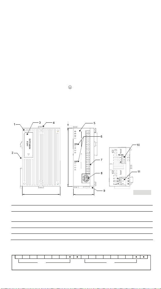
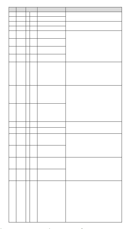
Product Profile & Dimensions
3 mm
DVP02LC
POWER
EXC+
RUN
EXC-
ERROR
SIG+
L.V
CH1
SIG-
SEN+
SEN-
NET
SHD
ZERO
MAX
MOTION
EXC+
90 mm
EXC-
SIG+
CH2
SIG-
NET
SEN+
ZERO
SEN-
MAX
SHD
MOTION
60 mm
33 mm
1. Mounting hole of the I/O module 2. DIN rail mounting slot (35mm)
3. I/O module connection port 4. I/O module clip
Status indicator
5.
(POWER, RUN, ERROR and L.V)
Function status indicator
6.
(NET, ZERO, MAX, MOTION)
7. I/O terminals 8. RS-232 port
9. Mounting slot clip 10. RS-485 port
11. DC power input
I/O Terminal Layout
SEN-SEN+SIG-SIG+EXC-EXC+ SIG+EXC-EXC+SHD SHDSEN-SEN +SIG-
DVP02LC-SL
CH1 CH2
- 1 -
[ Fi gure 1 ]
Page 3
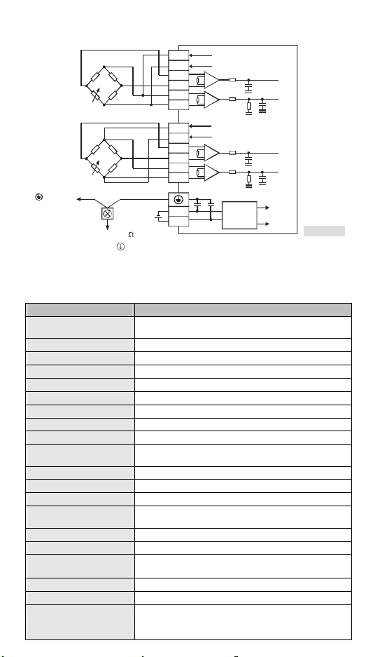
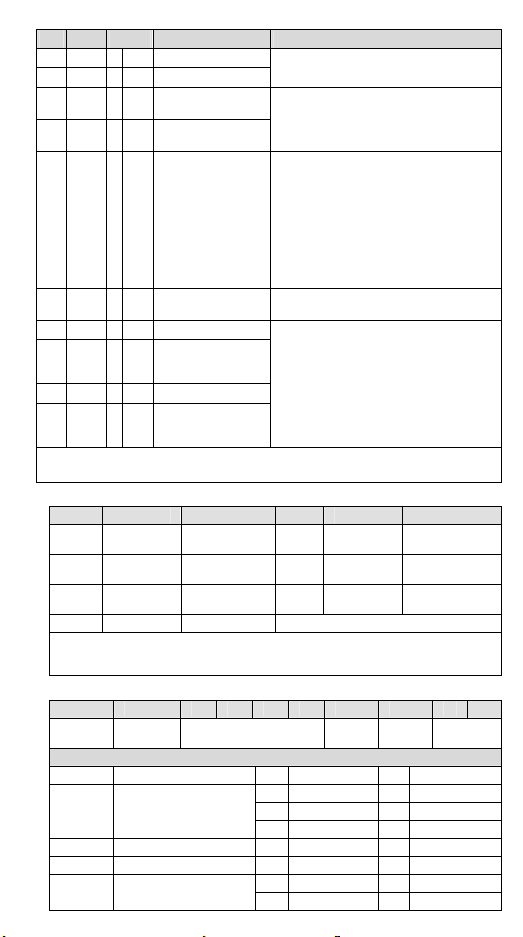
External Wiring
4 strain guage
6 strain guage
Terminal
of power
module
Note 1: Please connect the terminal on both the power module and Load Cell module to the system
earth point and ground the system contact or connect it to the cover of power distribution
cabinet.
Grounding
*1
System
grounding
(100 or less)
EXC+
EXCSIG+
SIG-
SEN+
SEN-
EXC+
EXCSIG+
SIG-
SEN+
SEN-
0V
24V
A+5V
AGND
A+5V
AGND
DC/DC
Converter
CH1
CH2
A+5V
AGND
[ Fig ure 2 ]
Electrical Specifications
Load cell module Voltage output
Rated power supply voltage/
power consumption
Voltage Boundary 18 to 31.2 VDC
Max. current consumption 125 mA
Input signal range ± 40 mVDC
Sensibility +5 VDC +/-10%
Internal resolution 24 bits
Communication port RS-232, RS-485
Applicable sensor type 4-wire or 6-wire strain gauge
Temperature coefficient span ≤ ± 50 ppm/K v. E
Temperature coefficient zero
point
Linearity error ≤ 0.02%
Response time 2, 10, 20, 40, 80 ms × channels
4 measuring ranges 0 to 1 mV/V, 0 to 2 mV/V, 0 to 4 mV/V, 0 to 6mV/V
Max. distance for connecting
to load cell
Max. current output 5 VDC * 300 mA
Permitted load cell resistance 40 to 4,010 Ω
Common mode rejection
(CMRR @50/60 Hz)
Dynamic value filter Setting range: K1 to K5
Average value filter Setting range: K1 to K100
Isolation method
24 VDC (-15 to +20%) / 3W
≤ ± 0.4 μV/K
100 M
≥100dB
500 VAC between digital circuits and Ground
500 VAC between analog circuits and Ground
500 VAC between analog circuits and digital circuits
- 2 -
Page 4
Load cell module Voltage output
Series connection to
DVP-PLC MPU
Operation / storage
temperature
Vibration / shock immunity
Complying with DIN1319-1, the tolerance of measured value should be ≤ 0.05% under 20°C
+ 10K temperature range
When the corrected ambient temperature and the actual temperature have a difference of
more than 10°C, it is suggested that you re-correct it.
Connectable to the left side of MPU, numbered from 100 to
107 according to the position of module from the closest to
farthest to MPU.
Operation: 0 to 55°C (temp.), 50 to 95% (humidity), pollution
degree 2
Storage: -25 to 70°C (temp.), 5 to 95% (humidity)
International standards: IEC61131-2, IEC 68-2-6 (TEST Fc)/
IEC61131-2 & IEC 68-2-27 (TEST Ea)
.
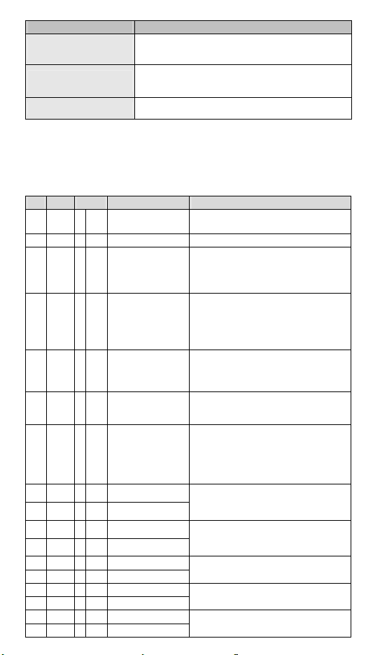
Control Register
CR# Add. Attrib. Register name Explanation
#0 H1000 O R Model name
#1 H1001 O R Firmware version Display the current firmware version in hex.
#2 H1002 O R/W Characteristic value
#3 H1003 O R/W
#4 H1004 O R
#6 H1006 X R/W
#7 H1007 O R/W
#8 H1008 O R/W CH1 tare weight
#9 H1009 O R/W CH2 tare weight
#10 H100A O R/W CH1 average times
#11 H100B O R/W CH2 average times
#12 H100C X R CH1 average weight
#13 H100D X R CH2 average weight
#14 H100E X R CH1 present weight
#15 H100F X R CH2 present weight
#16 H1010 O R/W CH1 standstill times
#17 H1011 O R/W CH2 standstill times
Reaction time for
measurement
Average value of all
channels
CH1 to CH2 read tare
weight
CH1 to CH2 gross/net
weight
Set up by the system:
DVP02LC-SL model code = H’4206
Mode 0 (H’0000): 1 mV/V
Mode 1 (H’0001): 2 mV/V, default
Mode 2 (H’0002): 4 mV/V
Mode 3 (H’0003): 6 mV/V
Mode 0 (H’0000): 2 ms
Mode 1 (H’0001): 10 ms
Mode 2 (H’0002): 20 ms
Mode 3 (H’0003): 40 ms
Mode 4 (H’0004): 80 ms, default
Sum up CH1 average value and CH2
average value and equalize them.
Equation: (CH1 average value + CH2
average value)/2
Read present average value as tare weight
value
bit0: CH1; bit1: CH2; bit2 to bit15: reserved
Display present weight as Gross (K0) or Net
(K1). bit0 to bit3: CH1; bit4 to bit7: CH2; bit8
to bit15: reserved.
Take CH1 for example: bit3 to bit0 = 0000,
gross; bit3 to bit0 = 0001, net; bit3 to bit0 =
1111, channel disabled.
The user can write in the weight or read it by
commands.
Default: K0; Range: -K32,768 to K32,767.
Default: K10; Range: K1 to K100.
When the set value exceeds the range, it will
automatically be changed to K1 or K100.
Display average weight.
Display present weight.
Default: K5
Range: K1 to K500
- 3 -
Page 5
CR# Add. Attrib. Register name Explanation
#18 H1012 O R/W CH1 standstill range
#19 H1013 O R/W CH2 standstill range
#20 H1014 O R/W CH1 decimal place
#21 H1015 O R/W CH2 decimal place
#22 H1016 O R/W
#23 H1017 O R/W
#24 H1018 O R/W
#25 H1019 O R/W
#26 H101A X R/W
#33 H1021 O R/W
#34 H1022 O R/W
CH1 unit of
measurement
CH1 unit of
measurement
CH2 unit of
measurement
CH2 unit of
measurement
Weight correction
command
CH1 weight base
point
CH2 weight base
point
#35 H1023 O R CH1 max. weight
#36 H1024 O R CH2 max. weight
#37 H1025 O R/W
#38 H1026 O R/W
#39 H1027 O R/W
#40 H1028 O R/W
#41 H1029 X R/W
Upper limit for CH1
zero point check
Upper limit for CH2
zero point check
Lower limit for CH1
zero point check
Lower limit for CH2
zero point check
Saving set value
(H’5678)
Default: K10
Range: K1 to K10,000
Default: K2
Range: K1 to K4
Enter max. 4 ASCII words.
CR#22, CR#24: High word
CR#23, CR#25: Low word
For the user to correct the weight.
Default: H’0000
H’0001: CH1 Reset to zero command
H’0002: CH1 Weight base point command
H’0003: CH2 Reset to zero command
H’0004: CH2 Weight base point command
For CR#33 to CR#34 default = K1,000;
Range: K-32,768 to K32,767
Steps for correction: Take CH1 for example
1: Place no weights on the load cell
2: Set up CR#26 command = “H’0001”
3: Place standard weights on load cell
4: Write the weight of the weights on the plate
into CR#33.
5: Set up CR#26 command = “H’0002”
Set up the max. weight. When the measured
value exceeds the set value, error codes will
be recorded.
Reference for reset to zero. When the weight
is within this range, the status code will be set
to “zero bit”, indicating the current zero
weight status.
Default: K10
Range: K-32,768 to K32,767
Reference for reset to zero. When the weight
is within this range, the status code will be set
to “zero bit”, indicating the current zero
weight status.
Default: K-10
Range: K-32,768 to K32,767
Save the present set value and write all the
set values into the internal Flash for use next
time DVP02LC-SL is switched on.
H0: No action, Default
H’FFFF: Saving is successful
H’5678: Write to internal Flash
When H’5678 is written in, all set values will
be saved in Flash. When the saving is
completed, CR#41 will become H’FFFF. If the
value written in is not H’5678, it will
automatically return to H0, e.g. write K1 into
CR# to return to K0.
- 4 -
Page 6
CR# Add. Attrib. Register name Explanation
#43 H102B X R/W CH1 filter percentage
#44 H102C X R/W CH2 filter percentage
#45 H102D X R/W
#46 H102E X R/W
#50 H1032 X R Status code
#51 H1033 X R Error code
#52 H1034 O R/W RS-232 node address
#53 H1035 O R/W
#54 H1036 O R/W RS-485 node address
#55 H1037 O R/W
Symbols: O means latched. X means not latched.
R means can read data. W means can write data.
c Error Code Table for CR#51:
bit Content Error bit Content Error
b0 K1 (H’0001)
b2 K4 (H’0004)
b4 K16 (H’0010)
b6 ~ b15 K64 (H’0040) Reserved
Note: Every error status is decided by its corresponding bit, so there might be more than
2 error statuses occurring at the same time. 0 refers to no error; 1 refers to error
occurring.
c Communication Format Table for CR#53, CR#55:
bit15 bit14~bit8 bit7 bit6 bit5 bit4 bit3 bit2 bit1 bit0
ACSII/RTU Reserved Baudrate
bit15 ACSII/RTU
bit7~bit4 Baudrate
bit3 Data length (RTU = 8 bits)
bit2 Stop bit
bit1~bit0 Parity
CH1 filter average
value
CH2 filter average
value
RS-232
communication
setting
RS-485
communication
setting
Power supply
abnormality
CH1 conversion
error
CH2 conversion
error
Default: K2
Range: K1 to K5 (Unit: 10%)
Display average weight after filtering.
Condition to enable filter: average time ≥ 30
b0 (H’0001): CH1 zero weight (empty)
b1 (H’0002): CH2 zero weight (empty)
b2 (H’0004): CH1 exceeds max. weight
(overload)
b3 (H’0008): CH2 exceeds max. weight
(overload)
b4 (H’0010): CH1 stable measured value
b5 (H’0020): CH2 stable measured value
b6 ~ b15: Reserved
Store all the error statuses. See “Error Code
Table” below. Default: H’0000
For CR#52, CR#54 default = 1
Range: K1 to K255
For CR#53, CR#55 default = H’0000; Range:
ASCII, 9600, 7, E, 1. See “Communication
Format Table” below.
b1 K2 (H’0002)
b3 K8 (H’0008)
b5 K32 (H’0020)
Data
Description
0 ASCII 1 RTU
0 9,600 bps 1 19,200 bps
2 38,400 bps 3 57,600 bps
4 115,200 bps 5 Else none
0 7 1 8
0 1 bit 1 2 bits
0 Even 1 Odd
2 None 3 None
- 5 -
length
Hardware
abnormality
CH1 SEN voltage
error
CH2 SEN voltage
error
Stop bit Parity
Page 7

……………………………………………………………… 繁體中文 …………………………………………………………………………
感謝您採用台達 DVP 系列產品。台達再度推出 Load Cell 秤重量測模組 DVP02LC-SL。
DVP02LC-SL 提供 24 bit 高解析度,可適用 4 或 6 線式的多種特徵值 Load Cell,可配合
客戶需求進行反應速度的搭配調整,輕易地滿足目前荷重應用市場上的全面需求。
a 請在使用之前,詳細閱讀本使用說明書。
a 實施配線前,務必關閉電源。於輸入電源切斷後,一分鐘之內,請勿觸摸內部電路。
a 本機為開放型(OPEN TYPE)機殼,因此使用者使用本機時,必須將之安裝於具防塵、
防潮及免於電擊∕衝擊意外之外殼配線箱內。另必須具備保護措施(如:特殊之工具
或鑰匙才可打開)防止非維護人員操作或意外衝擊本體,造成危險及損壞。
a 交流輸入電源不可連接於輸入∕出信號端,否則可能造成嚴重損壞,請在上電之前再
次確認電源配線,並請勿在上電時觸摸任何端子。
a 本體上之接地端子 務必正確的接地,可提高產品抗雜訊能力。
a 端子螺絲扭力為 1.95 kg-cm (1.7 in-lbs),並請使用 60/75°C 銅導線。
產品外觀尺寸與部位介紹
詳細圖示請參閱英文版頁碼 1 之[Figure 1],單位:mm。
1. I/O 模組定位孔 2. DIN 導軌槽 (35mm)
3. I/O 模組連接埠 4. I/O 模組固定扣
電源、運行、錯誤及低電壓指示燈
5.
(POWER, RUN, ERROR, L.V)
7. I/O 端子 8. RS-232 通訊埠
9. DIN 軌固定扣 10. RS-485 通訊埠
11. 電源輸入口
通道淨重、零點、最大值、穩定功能狀態
6.
燈 (NET, ZERO, MAX, MOTION)
輸入∕輸出端子台配置
請參閱英文版頁碼 1 之端子配置圖,在此語言版本省略說明。
外部配線
詳細圖示請參閱英文版頁碼 2 之[Figure 2]。
註 1:請將電源模組之 端及 Load Cell 秤重量測模組之 端連接到系統接地點,再將系統接
點作第三種接地或接到配電箱之機殼上。
規格
Load cell 模組 電壓輸出
電源額定電壓∕消耗功率 24 VDC (-15 ~ +20%) / 3W
電壓範圍 18 ~ 31.2 VDC
最大消耗電流 125 mA
輸入訊號範圍 ±40 mVDC
感測度 +5 VDC +/-10%
內部解析度 24 bits
通訊介面 RS-232, RS-485
適合感應器形式 4線制或 6 線制荷重單元(Load Cell)
溫度係數擴展 ≤ ± 50 ppm/K v. E
溫度係數偏移 ≤ ± 0.4 μV/K
線性誤差 ≤ 0.02%
- 6 -
Page 8

Load cell 模組 電壓輸出
反應時間 2, 10, 20, 40, 80 ms × 通道數
適用 Load Cell 特徵值 0 ~ 1, 0 ~ 2, 0 ~ 4, 0 ~ 6 mV/V
連接 Load Cell 最大距離 100 公尺
最大輸出電流 5 VDC * 300 mA
允許負載能力 40 ~ 4,010 Ω
共模拒斥比
(CMRR @50/60 Hz)
動態值濾波 可設定範圍 K1 ~ K5
平均功能 可設定範圍 K1 ~ K100
隔離方式
與 DVP-PLC 主機
連接說明
操作∕儲存環境
耐振動∕衝擊
符合 DIN1319-1 在量測範圍最終值為 20°C + 10K 的錯誤極限需 ≤ 0.05%。
Load Cell 校正環境溫度與實際操作溫度相差 10°C 以上時,建議重新校正以獲得最佳精確值。
100dB 以上
數位電路與接地之間:500 VAC
類比電路與接地之間:500 VAC
類比電路與數位電路之間:500 VAC
連接於主機左側,模組編號依靠近主機之順序自動編號由100 到
107。
操作:0 ~ 55°C(溫度),50 ~ 95%(濕度),污染等級 2
儲存:-25 ~ 70°C(溫度),5 ~ 95%(濕度)
國際標準規範 IEC 61131-2, IEC 68-2-6 (TEST Fc)/IEC 61131-2
& IEC 68-2-27 (TEST Ea)
控制暫存器 CR
位址 屬性 暫存器名稱 說明
CR#
#0 H1000 O R
#1 H1001 O R
#2 H1002 O R/W
#3 H1003 O R/W
#4 H1004 O R
#6 H1006 X R/W
#7 H1007 O R/W
#8 H1008 O R/W
#9 H1009 O R/W
#10 H100A O R/W
#11 H100B O R/W
機種型號 系統內定,DVP02LC-SL 機種代碼 = H’4206
韌體版本 16 進制,顯示目前韌體版本
特徵值
量測反應時間
總通道平均值
CH1 ~ CH2 皮重讀取
毛重/淨重顯示設定
CH1 皮重重量值
CH2 皮重重量值
CH1 平均次數
CH2 平均次數
模式 0 (H’0000):1 m V/V
模式 1 (H’0001):2 m V/V,預設值。
模式 2 (H’0002):4 m V/V
模式 3 (H’0003):6 m V/V
模式 0 (H’0000):2 m s
模式 1 (H’0001):10 ms
模式 2 (H’0002):20 ms
模式 3 (H’0003):40 ms
模式 4 (H’0004):80 ms,預設值。
以 CH1 平均值及 CH2 平均值做加總平均
計算式:( CH1 平均值 + CH2 平均值 ) ÷ 2
讀取目前的平均值做為皮重的重量值
bit0:CH1。bit1:CH2。bit2 ~ bit15:保留。
選擇目前重量顯示為毛重(K0) 或淨重(K1)
bit0~bit3:CH1。bit4~bit7:CH2。bit8~bit15:
保留。以 CH1 說明:bit3~bit0=0000,毛重。
bit3~bit0=0001,淨重。bi t3~ bi t0= 1111,關閉
通道。
使用者可自行寫入或由指令讀取皮重。
預設值 K0,設定值範圍 K-32768 ~ K32767。
設定範圍在 K1 ~ K100,預設值 K10。
設定值超過範圍時,則自動變更為臨界值 K1
或 K100。
- 7 -
Page 9

位址 屬性 暫存器名稱 說明
CR#
#12 H100C X R
#13 H100D X R
#14 H100E X R
#15 H100F X R
#16 H1010 O R/W
#17 H1011 O R/W
#18 H1012 O R/W
#19 H1013 O R/W
#20 H1014 O R/W
#21 H1015 O R/W
#22 H1016 O R/W
#23 H1017 O R/W
#24 H1018 O R/W
#25 H1019 O R/W
#26 H101A X R/W
#33 H1021 O R/W
#34 H1022 O R/W
#35 H1023 O R
#36 H1024 O R
#37 H1025 O R/W
#38 H1026 O R/W
#39 H1027 O R/W
#40 H1028 O R/W
#41 H1029 X R/W
#43 H102B X R/W
#44 H102C X R/W
#45 H102D X R/W
#46 H102E X R/W
CH1 平均重量
CH2 平均重量
CH1 現在重量
CH2 現在重量
CH1 穩定檢查次數
CH2 穩定檢查次數
CH1 穩定檢查範圍
CH2 穩定檢查範圍
CH1 小數點位數設定
CH2 小數點位數設定
CH1 重量量測單位
CH1 重量量測單位
CH2 重量量測單位
CH2 重量量測單位
調校重量指令
CH1 砝碼基點重量
CH2 砝碼基點重量
CH1 重量上限
CH2 重量上限
CH1 零點判斷檢查範
圍上限
CH2 零點判斷檢查範
圍上限
CH1 零點判斷檢查範
圍下限
CH2 零點判斷檢查範
圍下限
儲存設定值 (H’5678)
CH1 濾波比例設定
CH2 濾波比例設定
CH1 濾波平均值
CH2 濾波平均值
平均重量值顯示
現在重量值顯示
預設值 K5,設定值範圍 K1 ~ K500。
預設值 K10,設定值範圍 K1 ~ K10000。
設定範圍在 K1 ~ K4,預設值 K2。
ASCII 輸入,最多四個字元。
CR#22, CR#24 為 high word
CR#23, CR#25 為 low word
使用者調校重量使用,預設值 H’0000。
H’0001:CH1 歸零指令
H’0002:CH1 砝碼基點指令
H’0003:CH2 歸零指令
H’0004:CH2 砝碼基點指令
CR#33 ~ CR#34 預設值 K1000,設定值範圍
K-32768 ~ K32767。
使用者調整步驟:以 CH1 說明
Step1:荷重單元(Load Cell)上不放任何砝碼
Step2:CR#26 設定調整指令為”H’0001”
Step3:荷重單元(Load Cell)上加上標準砝碼
Step4:將目前底盤上的砝碼重量寫入CR#33
Step5:CR#26 設定調整指令為”H’0002”
使用者可設定最大重量值,當量測值超出設定
值時會記錄錯誤碼。
歸零狀態判斷參考,當重量值在此範圍內,狀
態碼會設定為歸零位元(zero bit),表示目前是
空載狀態。
預設值 K10,設定值範圍 K-32768 ~ K32767。
歸零狀態判斷參考,當重量值在此範圍內,狀
態碼會設定為歸零位元(zero bit),表示目前是
空載狀態。
預設值 K-10,設定值範圍 K-32768 ~ K32767。
儲存目前設定值,將目前所有設定值寫入內存
Flash,以待下次開機使用。
H0:不動作,預設值
H’FFFF:儲存成功
H’5678:寫入內存
寫入 H’5678 時會將所有設定值儲存於 Flash
中,當儲存完成後,CR#41 為 H’FFFF。若寫
入值不為 H’5678,則自動回復為 H0。例 如 CR#
寫入 K1,會回復為 K0。
預設值 K2,設定值範圍 K1 ~ K5(單位:10%)。
濾波後平均重量顯示
濾波功能啟動條件:當平均次數≥30。
- 8 -
Page 10

位址 屬性 暫存器名稱 說明
CR#
#50 H1032 X R
#51 H1033 X R
#52 H1034 O R/W
#53 H1035 O R/W
#54 H1036 O R/W
#55 H1037 O R/W
符號定義:O 表示為保持型。X 表示為非保持型。
R 表示為可讀取資料。W 表示為可寫入資料。
※ CR#51 錯誤狀態表:
bit 內容值 錯誤狀態 bit 內容值 錯誤狀態
b0 K1 (H’0001)
b2 K4 (H’0004)
b4 K16 (H’0010)
b6 ~
K64 (H’0040)
b15
註:每個錯誤狀態由相對應之位元決定,有可能會同時產生兩個以上之錯誤狀態,0 代表
正常無錯誤,1 代表有錯誤狀態產生。
※ CR#53、CR#55 通設格式:
bit15 bit14~bit8 bit7 bit6 bit5 bit4 bit3 bit2 bit1 bit0
ACSII/RTU 保留 串列傳輸速率 資料長度 停止位元 同位元
bit15 ACSII/RTU 0 ASCII 1 RTU
bit7~bit4 串列傳輸速率
bit3 資料長度 (RTU = 8 bits) 0 7 1 8
bit2 停止位元 0 1 bit 1 2 bits
bit1~bit0 同位元
狀態代碼
錯誤代碼
RS-232 站號
RS-232 通訊格式
RS-485 站號
RS-485 通訊格式
電源異常
CH1 轉換錯誤
CH2 轉換錯誤
保留
b0 (H’0001):CH1 零點重量(空載)
b1 (H’0002):CH2 零點重量(空載)
b2 (H’0004):CH1 超出重量上限(超載)
b3 (H’0008):CH2 超出重量上限(超載)
b4 (H’0010):CH1 量測值穩定
b5 (H’0020):CH2 量測值穩定
b6 ~ b15:保留
儲存所有錯誤狀態的資料暫存器,請參照錯誤
資訊表,預設值為 H’0000。
CR#52、CR#54 預設值 K1,設定值範圍
K1~K255。
CR#53、CR#55 通設格式,預設值 H’0000,
設定值範圍 ASCII, 9600, 7, E, 1,請參照通訊
格式資訊表。
b1 K2 (H’0002)
b3 K8 (H’0008)
b5 K32 (H’0020)
Description
0 9,600 bps 1 19,200 bps
2 38,400 bps 3 57,600 bps
4 115,200 bps 5 Else none
0 Even 1 Odd
2 None 3 None
硬體故障
CH1 SEN 電壓錯誤
CH2 SEN 電壓錯誤
- 9 -
Page 11

………………………………………………………………… 简体中文 ……………………………………………………………………
感谢您采用台达 DVP 系列产品。台达再度推出 Load Cell 秤重测量模块 DVP02LC-SL。
DVP02LC-SL 提供 24 bit 高分辨率,可适用 4 或 6 线式的多种特征值 Load Cell,可配合
客户需求进行反应速度的搭配调整,轻易地满足目前荷重应用市场上的全面需求。
a 请在使用之前,详细阅读本使用说明书。
a 实施配线前,务必关闭电源。于输入电源切断后,一分钟之内,请勿触摸内部电路。
a 本机为开放型(OPEN TYPE)机壳,因此使用者使用本机时,必须将其安装于具防尘、
防潮及免于电击∕冲击意外的外壳配线箱内。另必须具备保护措施(如:特殊的工具
或钥匙才可打开)防止非维护人员操作或意外冲击本体,造成危险及损坏。
a 交流输入电源不可连接于输入∕出信号端,否则可能造成严重损坏,请在上电之前再
次确认电源配线。请勿在上电时触摸任何端子。本体上的接地端子 务必正确的接
地,可提高产品抗干扰能力。
a 端子螺丝扭力为 1.95 kg-cm (1.7 in-lbs),并请使用 60/75°C 铜导线。
產品外觀尺寸與部位介紹
详细图示请参阅英文版页码 1 之[Figure 1],单位:mm。
1. I/O 模块定位孔 2. DIN 导轨槽 (35mm)
3. I/O 模块连接端口 4. I/O 模块固定扣
电源、运行、错误及低电压指示灯
5.
(POWER, RUN, ERROR, L.V)
7. I/O 端子 8. RS-232 通讯端口
9. DIN 轨固定扣 10. RS-485 通讯端口
11. 电源输入口
通道净重、零点、最大值、稳定功能状态
6.
灯 (NET, ZERO, MAX, MOTION)
輸入∕輸出端子台配置
请参阅英文版页码 1 之端子配置图,在此语言版本省略说明。
外部配線
详细图示请参阅英文版页码 2 之[Figure 2]。
注 1:请将电源模块的 端及 Load Cell 秤重测量模块的 端连接到系统接地点,再将系统
接点作第三种接地或接到配电箱的机壳上。
規格
Load cell 模块 电压输出
电源额定电压/消耗功率
电压范围
最大消耗电流 125 mA
输入讯号范围 ±40 mVDC
感测度 +5 VDC +/-10%
内部分辨率 24 bits
通讯接口 RS-232, RS-485
适合感应器形式 4线制或 6 线制荷重单元(Load Cell)
温度系数扩展 ≤ ± 50 ppm/K v. E
温度系数偏移 ≤ ± 0.4 μV/K
线性误差 ≤ 0.02%
24VDC (-15% ~ +20%) / 3W
18 ~ 31.2 VDC
- 10 -
Page 12

Load cell 模块 电压输出
响应时间 2, 10, 20, 40, 80 ms × 通道数
适用 Load Cell 特征值 0 ~ 1, 0 ~ 2, 0 ~ 4, 0 ~ 6 mV/V
连接 Load Cell 最大距离 100 公尺
最大输出电流 5 VDC * 300 mA
允许负载能力 40 ~ 4,010 Ω
共模拒斥比
(CMRR @50/60 Hz)
动态值滤波 可设定范围 K1 ~ K5
平均功能 可设定范围 K1 ~ K100
隔离方式
与 DVP-PLC 主机
连接说明
操作∕储存环境
耐振动∕冲击
符合 DIN1319-1 在测量范围最终值为 20°C + 10K 的错误极限需 ≤ 0.05%。
Load Cell 校正环境温度与实际操作温度相差 10°C 以上时,建议重新校正以获得最佳精确值。
100dB 以上
数字量电路与接地之间:500 VAC
模拟量电路与接地之间:500 VAC
模拟量电路与数字量电路之间:500 VAC
连接于主机左侧,模块编号依靠近主机之顺序自动编号由 100 到
107。
操作:0 ~ 55°C(温度),50 ~ 95%(湿度),污染等级 2
储存:-25 ~ 70°C(温度),5 ~ 95%(湿度)
国际标准规范 IEC 61131-2, IEC 68-2-6 (TEST Fc)/IEC 61131-2 &
IEC 68-2-27 (TEST Ea)
控制寄存器 CR
位址 属性 寄存器名称 说明
CR#
#0 H1000 O R
#1 H1001 O R
#2 H1002 O R/W
#3 H1003 O R/W
#4 H1004 O R
#6 H1006 X R/W
#7 H1007 O R/W
#8 H1008 O R/W
#9 H1009 O R/W
#10 H100A O R/W
#11 H100B O R/W
机种型号 系统内定,DVP02LC-SL 机种代码 = H’4206
韧体版本 16 进制,显示目前韧体版本
特征值
测量反应时间
总通道平均值
CH1~CH2 皮重读取
毛重/净重显示设定
CH1 皮重重量值
CH2 皮重重量值
CH1 平均次数
CH2 平均次数
模式 0 (H’0000):1 m V/V
模式 1 (H’0001):2 m V/V,默认值。
模式 2 (H’0002):4 m V/V
模式 3 (H’0003):6 m V/V
模式 0 (H’0000):2 m s
模式 1 (H’0001):10 ms
模式 2 (H’0002):20 ms
模式 3 (H’0003):40 ms
模式 4 (H’0004):80 ms,默认值。
以 CH1 平均值及 CH2 平均值做加总平均
计算式:( CH1 平均值 + H2 平均值 ) ÷ 2
读取目前的平均值做为皮重的重量值
bit0:CH1。bit1:CH2。bit2 ~ bit15:保留。
选择目前重量显示为毛重(K0) 或净重(K1)
bit0~bit3:CH1。bit4~bit7:CH2。bit8~bit15:
保留。以 CH1 说明:bit3~bit0=0000,毛重。
bit3~bit0=0001,净重。b it3 ~bi t0 =1111,关 闭
通道。
使用者可自行写入或由指令读取皮重。
默认值 K0,设定值范围 K-32768~ K32767。
设定范围在 K1 ~ K100,默认值 K10。
设定值超过范围时,则自动变更为临界值 K1
或 K100。
- 11 -
Page 13

位址 属性 寄存器名称 说明
CR#
#12 H100C X R
#13 H100D X R
#14 H100E X R
#15 H100F X R
#16 H1010 O R/W
#17 H1011 O R/W
#18 H1012 O R/W
#19 H1013 O R/W
#20 H1014 O R/W
#21 H1015 O R/W
#22 H1016 O R/W
#23 H1017 O R/W
#24 H1018 O R/W
#25 H1019 O R/W
#26 H101A X R/W
#33 H1021 O R/W
#34 H1022 O R/W
#35 H1023 O R
#36 H1024 O R
#37 H1025 O R/W
#38 H1026 O R/W
#39 H1027 O R/W
#40 H1028 O R/W
#41 H1029 X R/W
#43 H102B X R/W
#44 H102C X R/W
#45 H102D X R/W
#46 H102E X R/W
CH1 平均重量
CH2 平均重量
CH1 现在重量
CH2 现在重量
CH1 稳定检查次数
CH2 稳定检查次数
CH1 稳定检查范围
CH2 稳定检查范围
CH1 小数点位数设定
CH2 小数点位数设定
CH1 重量测量单位
CH1 重量测量单位
CH2 重量测量单位
CH2 重量测量单位
调校重量指令
CH1 砝码基点重量
CH2 砝码基点重量
CH1 重量上限
CH2 重量上限
CH1 零点判断检查范
围上限
CH2 零点判断检查范
围上限
CH1 零点判断检查范
围下限
CH2 零点判断检查范
围下限
储存设定值 (H’5678)
CH1 滤波比例设定
CH2 滤波比例设定
CH1 滤波平均值
CH2 滤波平均值
平均重量值显示
现在重量值显示
默认值 K5,设定值范围 K1 ~ K500。
默认值 K10,设定 值范围 K1 ~ K10000。
设定范围在 K1 ~ K4,默认 值 K2。
ASCII 输入,最多四个字符。
CR#22, CR#24 为 high word
CR#23, CR#25 为 low word
使用者调校重量使用,默认值 H’0000。
H’0001:CH1 归零指令
H’0002:CH1 砝码基点指令
H’0003:CH2 归零指令
H’0004:CH2 砝码基点指令
CR#33 ~ CR#34 默认值 K1000,设定值范围
K-32768 ~ K32767。
使用者调整步骤:以 CH1 说明
Step1:荷重单元(Load Cell)上不放任何砝码
Step2:CR#26 设定调整指令为“H’0001”
Step3:荷重单元(Load Cell)上加上标准砝码
Step4:将目前底盘上的砝码重量写入 CR#33
Step5:CR#26 设定调整指令为“H’0002”
使用者可设定最大重量值,当量测值超出设定
值时会记录错误码。
归零状态判断参考,当重量值在此范围内,状
态码会设定为归零位(zero bit),表示目前是空
载状态。
默认值 K10,设定值范围 K-32768 ~ K32767。
归零状态判断参考,当重量值在此范围内,状
态码会设定为归零位(zero bit),表示目前是空
载状态。
默认值 K-10,设定值范围 K-32768 ~ K32767。
储存目前设定值,将目前所有设定值写入内存
Flash,以待下次开机使用。
H0:不动作,默认值
H’FFFF:储存成功
H’5678:写入内存
写入 H’5678 时会将所有设定值储存于 Flash
中,当储存完成后,CR#41 为 H’FFFF。若写
入值不为 H’5678,则自动回复为 H0。例如
CR# 写入 K1,会回复为 K0。
默认值 K2,设定值范围 K1 ~ K5(单位:10%)
滤波后平均重量显示
滤波功能启动条件:平均次数≥30。
- 12 -
Page 14

位址 属性 寄存器名称 说明
CR#
#50 H1032 X R
#51 H1033 X R
#52 H1034 O R/W
#53 H1035 O R/W
#54 H1036 O R/W
#55 H1037 O R/W
符号定义:O 表示为保持型。X 表示为非保持型。
R 表示为可读取数据。W 表示为可写入数据。
※ CR#51 错误状态表:
Bit 内容值 错误状态 Bit 内容值 错误状态
b0 K1 (H’0001) 电源异常 b1 K2 (H’0002) 硬件故障
b2 K4 (H’0004) CH1 转换错误 b3 K8 (H’0008) CH1 SEN 电压错误
b4 K16 (H’0010) CH2 转换错误 b5 K32 (H’0020) CH2 SEN 电压错误
b6 ~
K64 (H’0040) 保留
b15
注:每个错误状态由相对应之位决定,有可能会同时产生两个以上之错误状态,0 代表正
常无错误,1 代表有错误状态产生。
※ CR#53、CR#55 通设格式:
bit15 bit14~bit8 bit7 bit6 bit5 bit4 bit3 bit2 bit1 bit0
ACSII/RTU 保留 波特率 数据长度 停止位 同位
bit15 ACSII/RTU 0 ASCII 1 RTU
bit7~bit4 波特率
bit3 数据长度 (RTU = 8 bits) 0 7 1 8
bit2 停止位 0 1 bit 1 2 bits
bit1~bit0 同位
状态代码
错误代码
RS-232 站号
RS-232 通讯格式
RS-485 站号
RS-485 通讯格式
b0 (H’0001):CH1 零点重量(空载)
b1 (H’0002):CH2 零点重量(空载)
b2 (H’0004):CH1 超出重量上限(超载)
b3 (H’0008):CH2 超出重量上限(超载)
b4 (H’0010):CH1 测量值稳定
b5 (H’0020):CH2 测量值稳定
b6 ~ b15:保留
储存所有错误状态的数据缓存器,请参照错误
信息表,默认值为 H’0000。
CR#52、CR#54 默认值 K1,设定值范围 K1 ~
K255。
CR#53、CR#55 通设格式,默认值 H’0000,
设定值范围 ASCII, 9600, 7, E, 1,请参照通讯
格式信息表。
Description
0 9,600 bps 1 19,200 bps
2 38,400 bps 3 57,600 bps
4 115,200 bps 5 Else none
0 Even 1 Odd
2 None 3 None
- 13 -
Page 15

………………………………………………………………… TÜRKÇE …………………………………………………………………
Delta’nın DVP serisi PLC’lerini seçtiğiniz için teşekkürler. Delta, load cell ile ağırlık
ölçümü için DVP02LC-SL modülünü sunar. DVP02LC-SL, 4-telli ve 6-telli özgün değerli
yük hücreleri (load cell) için uygulanabilir 24-bit çözünürlük sağlar. Buna bağlı olarak,
cevap zamanı (response time) kullanıcı ihtiyaçlarına göre herbiri ile koordinasyon
halinde çalışma için ayarlanabilir. Bu temelde, ağırlık ölçümünde pazar ihtiyaçları
rahatça karşılanabilir.
a Bu bilgi dökümanı ürünün elektriksel özellikleri, genel özellikleri, kurulumu ve
bağlantısı ile ilgili bilgiler sağlar.
a Bu ürün AÇIK TİP I/O modülü olduğu için toz, nem, elektrik şoku ve titreşimden uzak
yerlere kurulumu yapılmalıdır. Ürünün zarar görmemesi ve tehlike durumları
oluşmaması için yetkili olmayan kişilerin ürüne müdahale etmesini önleyecek
koruyucu önlemler alınmalıdır. (Örneğin ürünün bulunduğu panoya kilit konulması
gibi).
a Ürünün I/O terminallerine AC besleme bağlamayınız; aksi halde ciddi zararlar
meydana gelebilir. Ürüne enerji vermeden önce tüm bağlantıların doğru olduğunu
tekrar kontrol ediniz. Elektromanyetik gürültüyü önlemek için toprak terminalinin
düzgün topraklandığından emin olunuz.
a I/O terminal bloğu sıkma torku 1.95 kg-cm (1.7 in-lbs) olmalı ve sadece 60/75°C bakır
iletkenler kullanılmalıdır.
Ürün Profili & Ölçüler
İngilizce bölümde Şekil 1 [Figure 1]’e bakınız. Birim = mm
1. I/O modülü montaj yuvası 2. DIN ray montaj slotu (35mm)
3. I/O modül bağlantı portu 4. I/O modül klip
Durum indikatör
5.
(POWER, RUN, ERROR ve L.V)
7. I/O terminaller 8. RS-232 port
9. Montaj slot klipsi 10. RS-485 port
11. DC besleme girişi
Fonksiyon durum göstergesi
6.
(NET, ZERO, MAX, MOTION)
I/O Terminal Yerleşimi
İngilizce bölümde “terminal layout” şekline bakınız.
Harici Bağlantı
İngilizce bölümde Şekil 2 [Figure 2]’ye bakınız.
Not 1: Power modülü ve load cell modülü terminallerini sistemin toprak ucunda
birleştirdikten sonra topraklamayı güç dağıtım panelinin kasasına bağlayarak yapınız.
Elektriksel Özellikler
Load cell modülü Volt aj çıkışı
Besleme voltajı /Güç
tüketimi aralığı
Volt aj sınırları 18 to 31.2 VDC
Max. akım tüketimi 125 mA
Giriş sinyal aralığı ±40 mVDC
Hassasiyet +5 VDC +/-10%
Dahili çözünürlük 24 bits
24 VDC (-15 to +20%) / 3W
- 14 -
Page 16

Load cell modülü Volt aj çıkışı
Haberleşme portu RS-232, RS-485
Uygulanabilir sensör
tipi
Sıcaklık span Katsayısı ≤ ± 50 ppm/K v. E
Sıcaklık zero point
Katsayısı
Linearite hatası
Cevap Zamanı 2, 10, 20, 40, 80 ms × kanal
4 ölçme aralığı 0 to 1 mV/V, 0 to 2 mV/V, 0 to 4 mV/V, 0 to 6mV/V
Load cell bağlantısı için
maksimum mesafe
Max. Akım çıkışı 5 VDC * 300 mA
Müsade edilen load cell
direnci
Ortak mod reddetme
(CMRR @50/60 Hz)
Dinamik değer filtresi
Ortalama değer filtresi
İzolasyon metodu
DVP-PLC MPU’ya seri
bağlantı
Çalışma/Saklama
Sıcaklığı
Titreşim / Şok
Bağışıklığı
DIN1319-1 ile uyumlu, ölçüm değeri toleransı 20°C + 10K sıcaklık aralığında ≤ 0.05 %
olmalıdır.
Düzeltilmiş sıcaklık ortamı ve gerçek sıcaklık arasında 10°C’den fazla fark varsa, tekrar
düzeltilmesi önerilir.
4-telli veya 6-telli gerinim ölçer
≤ ± 0.4 μV/K
≤ 0.02%
100m
40 to 4,010 Ω
≥ 100dB
Ayar aralığı: K1 to K5
Ayar aralığı: K1 to K100
Dijital devreler ve Ground arası 500 VAC
Analog devreler ve ground arası 500 VAC
Analog devreler ve dijital devreler arası 500 VAC
MPU’nun sol kenarına bağlanabilir, MPU’ya uzaklığına göre
yakından uzağa doğru 100 – 107 arası adreslenir.
Çalışma: 0 to 55°C (sıcaklık), 50 to 95% (rutubet), kirlenme derece 2
Saklama: -25 to ~70°C (sıcaklık), 5 to 95% (rutubet)
Uluslararası standartlar: IEC61131-2, IEC 68-2-6 (TEST Fc)/
IEC61131-2 & IEC 68-2-27 (TEST Ea)
Kontrol Register
CR# Add. Özellik Register adı Açıklama
#0 H1000 O R Model adı
#1 H1001 O R Yazılım versiyonu
#2 H1002 O R/W Karakteristik Değer
#3 H1003 O R/W
#4 H1004 O R
Ölçüm için tepki
zamanı
Tüm kanalların
ortalama değeri
Sistem tarafından ayarlanır:
DVP02LC-SL model kodu = H’4206
Mevcut yazılım versiyonunu Hex. olarak
gösterir.
Mod 0 (H’0000) : 1 mV/V
Mod 1 (H’0001) : 2 mV/V (Varsayılan)
Mod 2 (H’0002) : 4 mV/V
Mod 3 (H’0003) : 6 mV/V
Mod 0 (H’0000): 2 ms
Mod 1 (H’0001): 10 ms
Mod 2 (H’0002): 20 ms
Mod 3 (H’0003): 40 ms
Mod 4 (H’0004): 80 ms (Varsayılan)
CH1 ortalama değeri ve CH2 ortalama değeri
toplamını alır ve eşitler.
Eşitleme: (CH1 ortalama değeri + CH2
ortalama değeri) / 2
- 15 -
Page 17

CR# Add. Özellik Register adı Açıklama
#6 H1006 X R/W
CH1~2 brüt (daralı)
ağırlık okuma
#7 H1007 O R/W CH1~2 brüt/net ağırlık
#8 H1008 O R/W CH1 dara ağırlığı
#9 H1009 O R/W CH2 dara ağırlığı
#10 H100A O R/W CH1 ortalama adeti
#11 H100B O R/W CH2 ortalama adeti
#12 H100C X R CH1 ortalama ağırlık
#13 H100D X R CH2 ortalama ağırlık
#14 H100E X R CH1 mevcut ağırlık
#15 H100F X R CH2 mevcut ağırlık
#16 H1010 O R/W CH1 durgunluk adeti
#17 H1011 O R/W CH2 durgunluk adeti
#18 H1012 O R/W CH1 durgunluk aralığı
#19 H1013 O R/W CH2 durgunluk aralığı
#20 H1014 O R/W CH1 ondalık yeri
#21 H1015 O R/W CH2 ondalık yeri
#22 H1016 O R/W CH1 ölçüm birimi
#23 H1017 O R/W CH1 ölçüm birimi
#24 H1018 O R/W CH2 ölçüm birimi
#25 H1019 O R/W CH2 ölçüm birimi
#26 H101A X R/W
#33 H1021 O R/W
#34 H1022 O R/W
Ağırlık düzeltme
komutu
CH1 ağırlık temel
noktası
CH2 ağırlık temel
noktası
#35 H1023 O R CH1 max. ağırlık
#36 H1024 O R CH2 max. ağırlık
#37 H1025 O R/W
#38 H1026 O R/W
CH1 sıfır noktası
kontrol üst limiti
CH2 sıfır noktası
kontrol üst limiti
Mevcut ortalama değeri brüt ağırlık olarak
okur. bit0: CH1; bit1: CH2; bit2 ~ bit15:
rezerve
Mevcut ağırlığı Net (k0) veya Brüt (K1)
gösterir. bit0 ~ bit3: CH1; bit4~bit7: CH2; bit8
~ bit15: rezerve.
CH1 örneği: bit3 ~ bit0=0000, Brüt; bit3 ~
bit0=0001, Net; bit3 ~ bit0=1111, kanal pasif.
Kullanıcılar ağırlığı yazabilir veya komutlar ile
okuyabilir.
Var sa yılan: K0; Aralık: -K32,768 ~ K32,767.
Var sa yılan: K10; Aralık: K1 ~ K100.
Set değeri aralığı aştığı zaman, otomatik
olarak K1 ve K100 olarak değişir.
Ortalama ağırlığı gösterir.
Mevcut ağırlığı gösterir.
Var sa yılan: K5
Aralık: K1 ~ K500
Var sa yılan: K10
Aralık: K1 ~ K1,000
Var sa yılan: K2
Aralık: K1 ~ K4
Maksimum 4 ASCII word girilir.
CR#22, CR#24: Yüksek word
CR#23, CR#25: Düşük word
Kullanıcıların ağırlığı düzeltmesi için.
Var sa yılan: H’0000
H’0001: CH1 Sıfır komutuna resetle
H’0002: CH1 Ağırlık taban noktası komutu
H’0003: CH2 Sıfır komutuna resetle
H’0004: CH2 Ağırlık taban noktası komutu
CR#33~CR#34 için Varsayılan = K1,000;
Aralık: K-32,768 ~ K32,767
Düzeltme adımları: CH1 örneği
1: Load cell üzerine hiçbir ağırlık koymayınız.
2: CR#26 komutunu “H’0001” ayarlayınız.
3: Load cell üzerine standart ağırlığı
yerleştiriniz
4: Tabaka üzerindeki ağırlığı ikinci ağırlık
değeri olarak CR#33 içine yazınız.
5: CR#26 komutunu “H’0002” ayarlayınız
Maksimum ağırlık ayarı. Ölçüm değeri set
değerini aştığı zaman, hata kodları
kaydedilecek.
Sıfıra resetlemek için referans. Ağırlık bu
aralığın için de olduğu zaman, durum (Status)
kodu mevcut ağırlık durumunu gösteren
“zero bitini” set edecek.
Var sa yılan: K10
Aralık: K-32,768 ~ K32,767
- 16 -
Page 18

CR# Add. Özellik Register adı Açıklama
#39 H1027 O R/W
#40 H1028 O R/W
#41 H1029 X R/W
#43 H102B X R/W CH1 filtre yüzdesi
#44 H102C X R/W CH2 filtre yüzdesi
#45 H102D X R/W
#46 H102E X R/W
#50 H1032 X R Status (durum) kodu
#51 H1033 X R Hata kodu
#52 H1034 O R/W RS-232 slave adresi
#53 H1035 O R/W
#54 H1036 O R/W RS-485 slave adresi
#55 H1037 O R/W
Sembol:
O: Kalıcı; X: Kalıcı-değil; R: Okunabilir data; W: Yazılabilir data.
c CR#51 için Hata Kodu Tablosu:
bit İçeriği Hata bit İçeriği Hata
b0 K1 (H’0001)
b2 K4 (H’0004) CH1 dönüşüm hatası b3 K8 (H’0008) CH1 SEN voltaj hatası
b4 K16 (H’0010) CH2 dönüşüm hatası b5 K32 (H’0020) CH2 SEN voltaj hatası
b6 ~
K64 (H’0040) Rezerve
b15
Not: Her hata durumu ona karşılık gelen bir bit ile tanımlanır. Aynı anda 2 veya daha fazla
hata meydana gelebilir. 0 hata olmadığını; 1 hata olduğunu gösterir.
CH1 sıfır noktası
kontrol alt limiti
CH2 sıfır noktası
kontrol alt limiti
Set değeri kaydetme
(H’5678)
CH1 filtre ortalama
değeri
CH2 filtre ortalama
değeri
RS-232 haberleşme
formatı
RS-485 haberleşme
formatı
Power supply
anormal
Sıfıra resetlemek için referans. Ağırlık bu
aralığın için de olduğu zaman, durum (status)
kodu mevcut ağırlık durumunu gösteren
“zero bitini” set edecek.
Var sa yılan: K-10
Aralık: K-32,768 ~ K32,767
Mevcut set değerini kaydeder ve
DVP02LC-SL daha sonra enerjilendiğinde
kullanabilmesi için tüm set değerlerini dahili
flash içine yazar.
H0: Çalışma yok, Varsayılan
H’FFFF: Kayıt başarılı
H’5678: Dahili Flash’a yazar.
H’5678 yazıldığı zaman, tüm set değerleri
Flash içine kaydedilecek. Kayıt tamamlandığı
zaman, CR#41 H’FFFF olacak. Eğer yazılan
değer H’5678 değilse, otomatik olarak H0’a
dönecek. Örneğin CR# içine K1 yazılırsa
K0’a dönecek.
Default: K2; Aralık: K1 ~ K5 (Birim: 10%)
Filtrelemeden sonra ortalama ağırlığı gösterir
Filtre aktif etme şart: ortalama zam an ≥ 30
b0 (H’0001): CH1 sıfır ağırlık (boş)
b1 (H’0002): CH2 sıfır ağırlık (boş)
b2 (H’0004): CH1 maksimum ağırlığı aşar
(aşırı yük)
b3 (H’0008): CH2 maksimum ağırlığı aşar
(aşırı yük)
b4 (H’0010): CH1 sabit ölçüm değeri
b5 (H’0020): CH2 sabit ölçüm değeri
b6 ~ b15: Rezerve
Tüm hata durumlarını kaydeder. Lütfen
aşağıdaki “Hata kodu tablosu” na bakınız.
Var sa yılan: H’0000
CR#52, CR#54 için Varsayılan = 1; Aralık: K1
~ K255
CR#53, CR#55 için Varsayılan = H’0000;
Aralık: ASCII, 9600, 7, E ,1. “Haberleşme
Formatı Tablosu” na bakınız.
b1 K2 (H’0002) Hardware anormal
- 17 -
Page 19

c CR#53, CR#55 için Haberleşme Formatı Tablosu:
bit15 bit14 ~ bit8 bit7 bit6 bit5 bit4 bit3 bit2 bit1 bit0
ACSII/RTU Rezerve Baudrate
bit15 ASCII / RTU 0 ASCII 1 RTU
bit7 ~ bit4 Baudrate
bit3 Data uzunluğu (RTU = 8 bits) 0 7 1 8
bit2 Stop bit 0 1 bit 1 2 bits
bit1 ~ bit0 Parity
Açıklama
0 9,600 bps 1 19,200 bps
2 38,400 bps 3 57,600 bps
4 115,200 bps 5 Else none
0 Even 1 Odd
2 None 3 None
Data
Uzunluğu
Stop bit Parity
- 18 -
 Loading...