

Page 1

User‘s Guide
Dell C7017T
Regulatory model: C7017Tf
Page 2

NOTE: A NOTE indicates important information that helps you make better use of
your computer.
CAUTION: A CAUTION indicates potential damage to hardware or loss of data if
instructions are not followed.
WARNING: A WARNING indicates a potential for property damage, personal
injury, or death.
© 2016 Dell Inc. All rights reserved.
Information in this document is subject to change without notice. Reproduction of these materials
in any manner whatsoever without the written permission of Dell Inc. is strictly forbidden.
Trademarks used in this text: Dell™ and the DELL logo are trademarks of Dell Inc.; Microsoft®,
Windows®, and the Windows start button logo are either trademarks or registered trademarks of
Microsoft Corporation in the United States and/or other countries.
Other trademarks and trade names may be used in this document to refer to either the entities
claiming the marks and names or their products. DellInc. disclaims any proprietary interest in
trademarks and trade names other than its own.
2016 –06 Rev. A00
2
Page 3

Contents
About Your Monitor ..................................... 5
Package Contents . . . . . . . . . . . . . . . . . . . . . . . . . . . . . . . .5
Product Features . . . . . . . . . . . . . . . . . . . . . . . . . . . . . . . . 7
Remote Control . . . . . . . . . . . . . . . . . . . . . . . . . . . . . . . . . 8
Identifying Parts and Controls . . . . . . . . . . . . . . . . . . . . . . . . 11
Monitor Specifications . . . . . . . . . . . . . . . . . . . . . . . . . . . . 14
Plug and Play Capability . . . . . . . . . . . . . . . . . . . . . . . . . . . 23
LCD Monitor Quality & Pixel Policy . . . . . . . . . . . . . . . . . . . . . 27
Maintenance Guidelines . . . . . . . . . . . . . . . . . . . . . . . . . . . 28
Setting Up the Monitor.................................. 29
Connecting Your Monitor . . . . . . . . . . . . . . . . . . . . . . . . . . 29
Wall Mounting . . . . . . . . . . . . . . . . . . . . . . . . . . . . . . . . . 32
Operating the Monitor .................................. 33
Power On the Monitor . . . . . . . . . . . . . . . . . . . . . . . . . . . . 33
Using the Front-Panel Controls . . . . . . . . . . . . . . . . . . . . . . . 33
Using the On-Screen Display (OSD) Menu. . . . . . . . . . . . . . . . . 34
Setting the Maximum Resolution . . . . . . . . . . . . . . . . . . . . . . 50
Dell Web Management for Monitors . . . . . . . . . . . . . . . . . . . . 52
3
Page 4

Troubleshooting ....................................... 58
Self-Test . . . . . . . . . . . . . . . . . . . . . . . . . . . . . . . . . . . . . 58
Built-in Diagnostics . . . . . . . . . . . . . . . . . . . . . . . . . . . . . . 59
Common Problems . . . . . . . . . . . . . . . . . . . . . . . . . . . . . . 60
Product-Specific Problems. . . . . . . . . . . . . . . . . . . . . . . . . . 63
Universal Serial Bus (USB) Specific Problems . . . . . . . . . . . . . . . 64
Mobile High-Definition Link (MHL) Specific Problems . . . . . . . . . 65
Touch Problems . . . . . . . . . . . . . . . . . . . . . . . . . . . . . . . . 65
Ethernet Problems . . . . . . . . . . . . . . . . . . . . . . . . . . . . . . . 66
Appendix .............................................. 67
Safety Instructions . . . . . . . . . . . . . . . . . . . . . . . . . . . . . . . 67
FCC Notices (U.S. Only) and Other Regulatory Information. . . . . . 67
Contact Dell. . . . . . . . . . . . . . . . . . . . . . . . . . . . . . . . . . . 67
4
Page 5
About Your Monitor
Package Contents
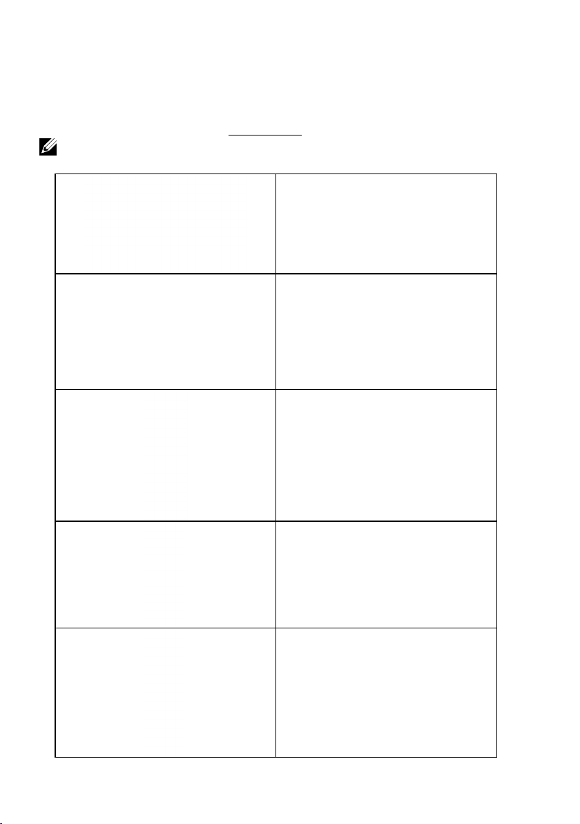
Your monitor ships with all the components shown below. Ensure that you have
received all the components and Contact Dell if anything is missing.
NOTE: Some items may be optional and may not ship with your monitor. Some
features or media may not be available in certain countries.
•Monitor
•Remote Control & Batteries (AAA x 2)
•Remote control holder
•Stylus
•Stylus holder
About Your Monitor 5
Page 6
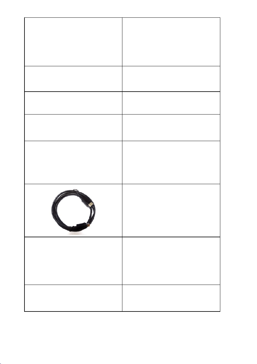
•LSA1U Wall Mount Kit
•Wire Saddle
•Power Cable (varies with countries)
•VGA Cable
•HDMI Cable
•DP Cable
•USB 3.0 upstream cable (enables the
USB ports on the monitor)
•Drivers and Documentation media
•Quick Setup Guide
•Safety and Regulatory Information
6 About Your Monitor
Page 7

Product Features
The Dell C7017T flat-panel display has an active matrix, Thin-Film Transistor, Liquid
Crystal Display and LED backlight. The monitor’s features include:
• C7017T: 176.563 cm (69.513 inches) diagonal viewable image size, 1920 x 1080
resolution, plus full-screen support for lower resolutions.
• Video Electronics Standards Association (VESA) 400 mm mounting holes.
• Plug and play capability if supported by your system.
• On-Screen Display (OSD) adjustments for ease of set-up and screen optimization.
• Software and documentation media which includes an information file (INF), Image
Color Matching File (ICM), and product documentation.
• Dell Display Manager Software.
• ENERGY STAR certificated.
• Asset Management Capability.
• CECP (for China).
• Energy Gauge shows the energy level being consumed by the monitor in real time.
• Analog backlight dimming control for flicker free display.
About Your Monitor 7
Page 8

Remote Control
3. Up
Press to move the selection up
in OSD menu.
4. Left
Press to move the selection left
in OSD menu.
5. Down
Press to move the selection
down in OSD menu.
6. Menu
Press to turn on the OSD menu.
7. Brightness -
Press to decrease the Brightness.
8. Volume -
Press to decrease the Volume.
9. MUTE
Press to turn the mute function
on/off.
10.Preset Modes
Display information about Preset
Modes.
11. Right
Press to move the selection
right in OSD menu.
12. OK
Confirm an entry or selection.
13. Exit
Press to exit the Menu.
1. Power On/Off
Switch this monitor on or off.
2. Input Source
Select input source. Press
button to select from VGA or DP or
HDMI1 or HDMI2 or HDMI3 . Press
button to confirm and exit.
8 About Your Monitor
or
14. Brightness +
Press to increase the Brightness.
15. Volume +
Press to increase the Volume.
Page 9

How to enter and exit White Board Mode :
The OSD menu must not be on the screen for this feature, Press button, the White
Board Mode be active, Press
button ,the mode is disabled.
Inserting the batteries in the remote control
The remote control is powered by two 1.5V AAA batteries.
To install or replace batteries:
1. Press and then slide the cover to open it.
2. Align the batteries according to the (+) and (–) indications inside the
battery compartment.
3. Replace the cover.
CAUTION: The incorrect use of batteries can result in leaks or bursting. Be
sure to follow these instructions:
• Place “AAA” batteries matching the (+) and (–) signs on each battery to the (+) and
(–) signs of the battery compartment.
• Do not mix battery types.
• Do not combine new batteries with used ones. It causes shorter life or leakage of
batteries.
• Remove the dead batteries immediately to prevent them from liquid leaking in the
battery compartment. Don’t touch exposed battery acid, as it can damage your
skin.
NOTE: If you do not intend to use the remote control for a long period, remove the
batteries.
Handling the remote control
• Do not subject to strong shock.
• Do not allow water or other liquids to splash on the remote control. If the remote
control gets wet, wipe it dry immediately.
• Avoid exposure to heat and steam.
• Other than to install the batteries, do not open the remote control.
About Your Monitor 9
Page 10

Operating range of the remote control
Point the top of the remote control toward the LCD monitor’s remote sensor
during button operation.
Use the remote control within a distance of about 8 m from remote control
sensor or at a horizontal and vertical angle of within 15° within a distance of
about 5.6 m.
NOTE: The remote control may not function properly when the remote control
sensor on the display is under direct sunlight or strong illumination, or when there is
an obstacle in the path of signal transmission.
10 About Your Monitor
Page 11
Identifying Parts and Controls
Front View
1 IR Lens (with LED indicator)
Function buttons (For more information, see Operating the Monitor)
2
3 Power On/Off button (with LED indicator)
About Your Monitor 11
Page 12
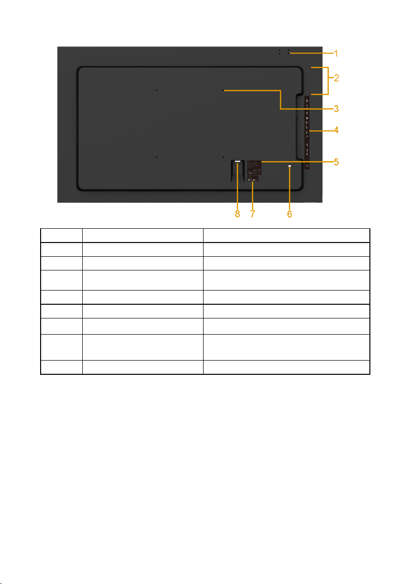
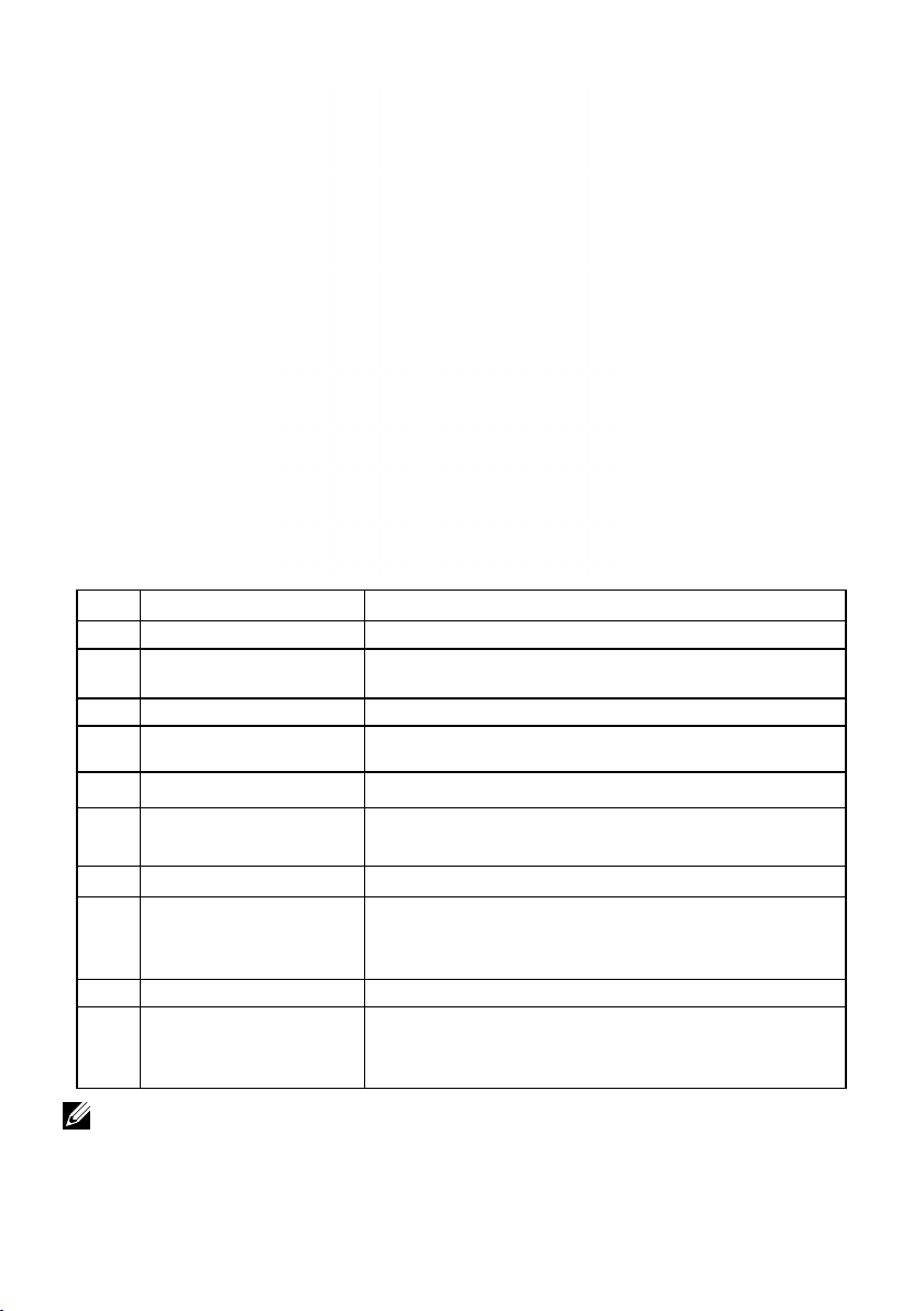
Back View
Label Description Use
1 Screw Hole For Accessory mounting.
2 Wire Saddle hole For accessory wire saddle placement.
3 VESA mounting holes (400
mm)
4 RCA label Indicates the connector type.
5 Regulatory rating label Lists the regulatory approvals.
6 RJ-45 connector For remote control use.
7 Barcode serial number label Refer to this label if you need to contact
8 AC power connector Connect the monitor power cable.
To mount the monitor.
Dell for technical support.
12 About Your Monitor
Page 13
Side View
Label Description Use
1 RS232 connector Connect your computer with RS232 cable.
2 Audio Out Connect the soundbar mini stereo plug (Supports
3 Audio in Analog audio (two channel) input.
4 VGA connector Connect your computer to the monitor with VGA
5 DisplayPort connector Connect your computer with DP cable.
6
HDMI/MHL connector
7 HDMI connector Connect your computer with HDMI cable.
8 USB Down Stream Port
(Dedicated Charging
Port)
9 USB Down Stream Port Connect your USB devices.
10 USB upstream port Connect the USB cable that came with your monitor
two channel output ).
cable.
Connect your computer with HDMI cable.
Connect your MHL devices with MHL cable.
Connect your USB devices for charging.
DCP port is for charging devices and has no data
lines.
to the computer. Once this cable is connected, you
can use the USB connectors on the monitor.
NOTE: Excessive sound pressure from ear-/headphones can cause hearing damage/
hearing loss.
About Your Monitor 13
Page 14
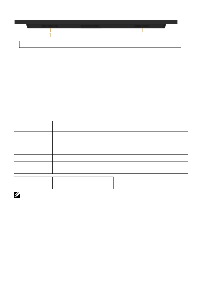
Bottom View
1 Speakers
Monitor Specifications
The following sections give you information about the various power management
modes and pin assignments for the various connectors of your monitor.
Power Management Modes
If you have VESA’s DPM compliance display card or software installed in your PC, the
monitor automatically reduces its power consumption when not in use. This is referred
to as Power Save Mode. If the computer detects input from keyboard, mouse, or other
input devices, the monitor automatically resumes functioning. The following table
shows the power consumption and signaling of this automatic power-saving feature:
VESA Modes
Normal operation Active Active Active White 230 W (Maximum)**
Active-off mode Inactive Inactive Blank Glowing
Switch off - - Off Less than 0.3 W *
Network Standby
mode
Horizontal
Sync
Inactive Inactive Blank Glowing
Vertical
Sync
Video
Power
Indicator
white
white
Power Consumption
145 W (Typical)
Less than 0.5 W
Less than 3 W
Energy Star Power Consumption
P
ON
NOTE: Based on IEC/EN 62301 test method, the power consumption of Active-off
mode & Switch off mode is measured with the network disabled.
It supports normal operation & Network Standby mode While enable to network
feature.
-
120 W***
14 About Your Monitor
Page 15
The OSD will only function in the normal operation mode. When any button except
power button is pressed in Active-off mode, the following messages will be displayed:
Activate the computer and monitor to gain access to the OSD.
NOTE: The Dell C7017T monitor is ENERGY STAR®-certificated.
* Zero-power consumption in OFF mode can only be achieved by disconnecting the
main cable from the monitor.
** Maximum power consumption with max luminance and contrast.
*** Energy consumption (On Mode) is tested at 230 Volts / 50 Hz.
This document is informational only and reflects laboratory performance. Your
product may perform differently, depending on the software, components and
peripherals you ordered and shall have no obligation to update such information.
Accordingly, the customer should not rely upon this information in making
decisions about electrical tolerances or otherwise. No warranty as to accuracy or
completeness is expressed or implied.
About Your Monitor 15
Page 16
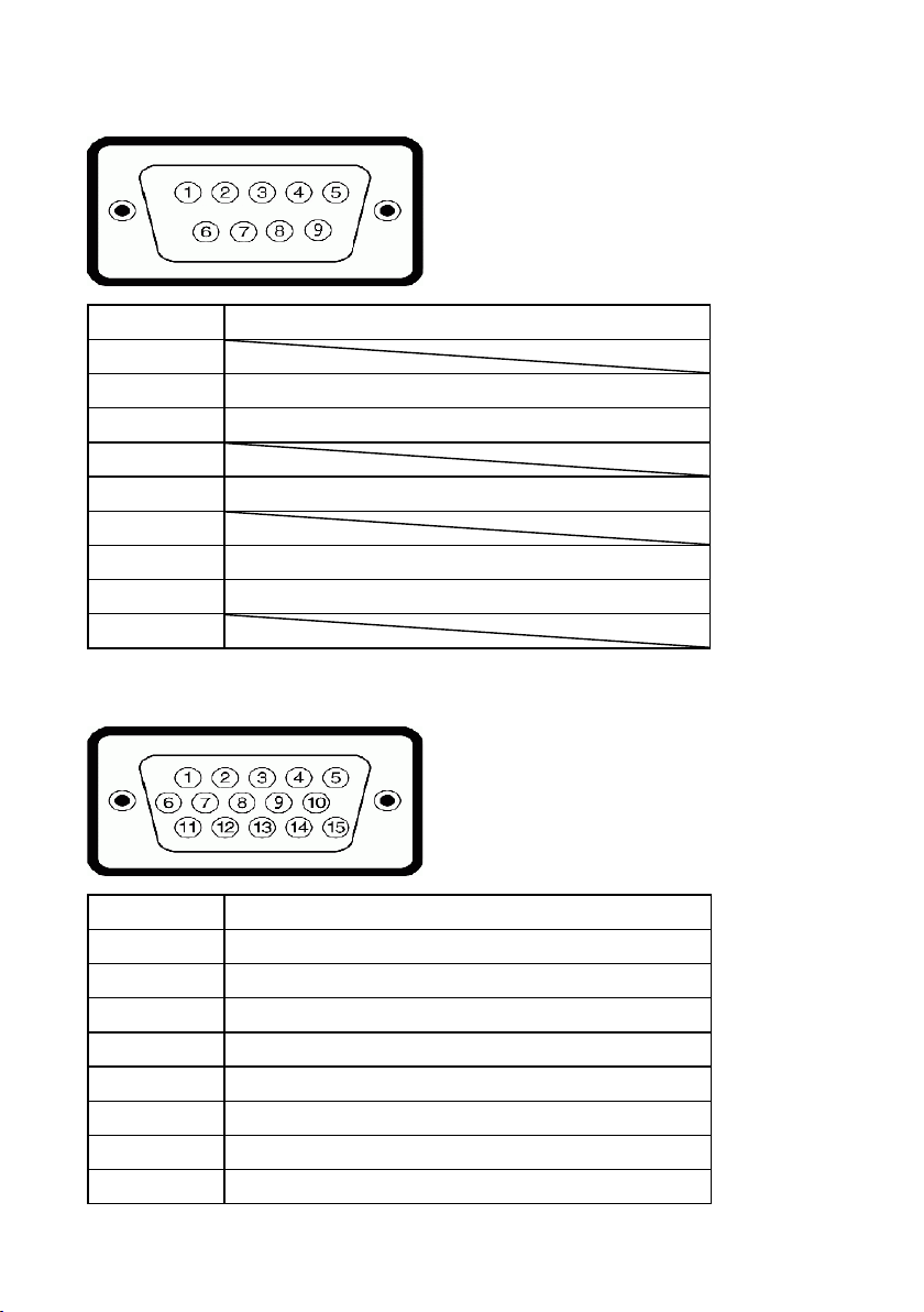
Pin Assignments
RS232 connector
Pin Number Monitor Side of the 9-pin Side Signal Cable
1
2 RX
3 TX
4
5 GND
6
7 Not Used
8 Not Used
9
VGA connector
Pin Number Monitor Side of the 15-pin Side Signal Cable
1 Video-Red
2 Video-Green
3 Video-Blue
4 GND
5 Self-test
6 GND-R
7 GND-G
8 GND-B
16 About Your Monitor
Page 17
9 DDC +5 V
10 GND-sync
11 GND
12 DDC data
13 H-sync
14 V-sync
15 DDC clock
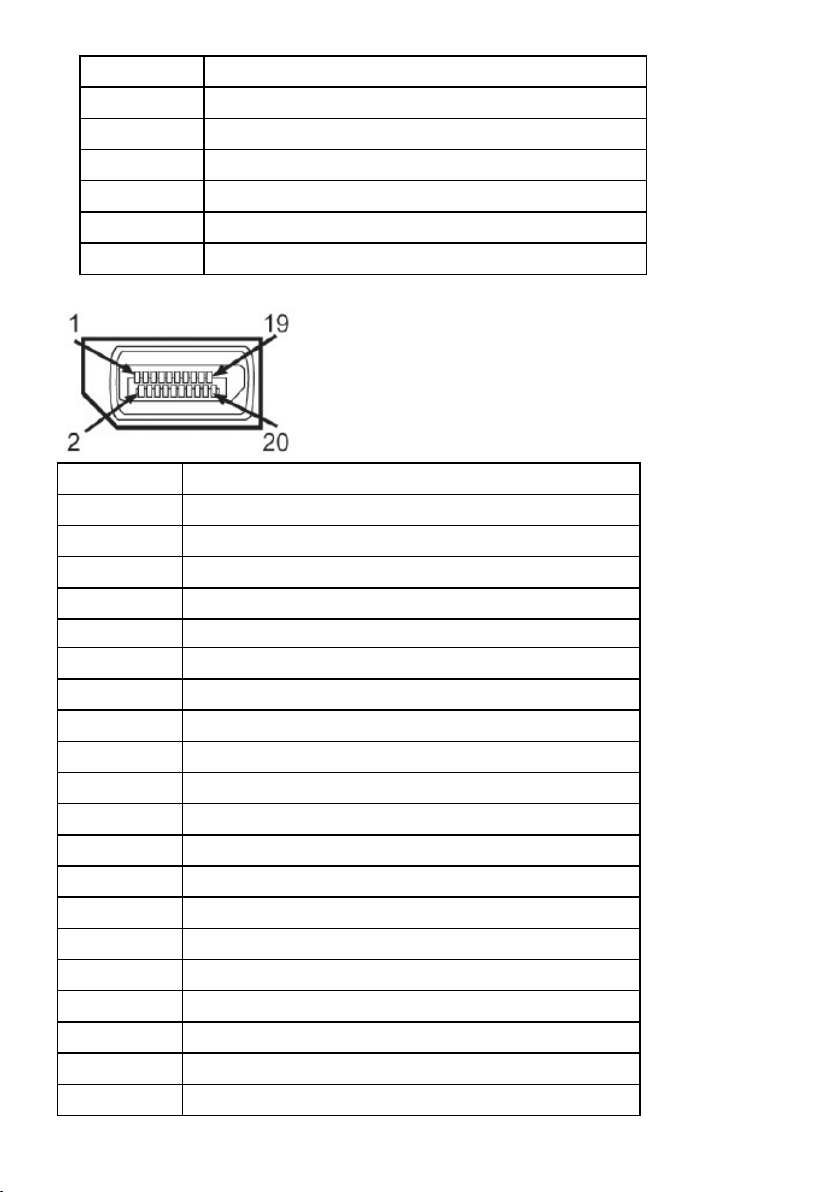
DisplayPort Connector
Pin Number 20-pin Side of the Connected Signal Cable
1 ML0(p)
2 GND
3 ML0(n)
4 ML1(p)
5 GND
6 ML1(n)
7 ML2(p)
8 GND
9 ML2(n)
10 ML3(p)
11 GND
12 ML3(n)
13 GND
14 GND
15 AUX(p)
16 GND
17 AUX(n)
18 HPD
19 DP_PWR_Return
20 +3.3 V DP_PWR
About Your Monitor 17
Page 18
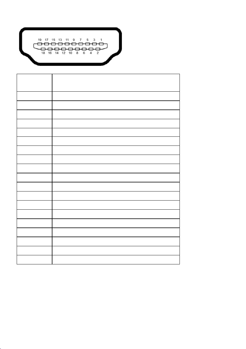
HDMI Connector
Pin Number 19-pin Side of the Connected Signal Cable
1 TMDS DATA 2+
2 TMDS DATA 2 SHIELD
3 TMDS DATA 24 TMDS DATA 1+
5 TMDS DATA 1 SHIELD
6 TMDS DATA 1-
7 TMDS DATA 0+
8 TMDS DATA 0 SHIELD
9 TMDS DATA 0-
10 TMDS CLOCK+
11 TMDS CLOCK SHIELD
12 TMDS CLOCK13 CEC
14 Reserved (N.C. on device)
15 DDC CLOCK (SCL)
16 DDC DATA (SDA)
17 DDC/CEC Ground
18 +5V POWER
19 HOT PLUG DETECT
18 About Your Monitor
Page 19
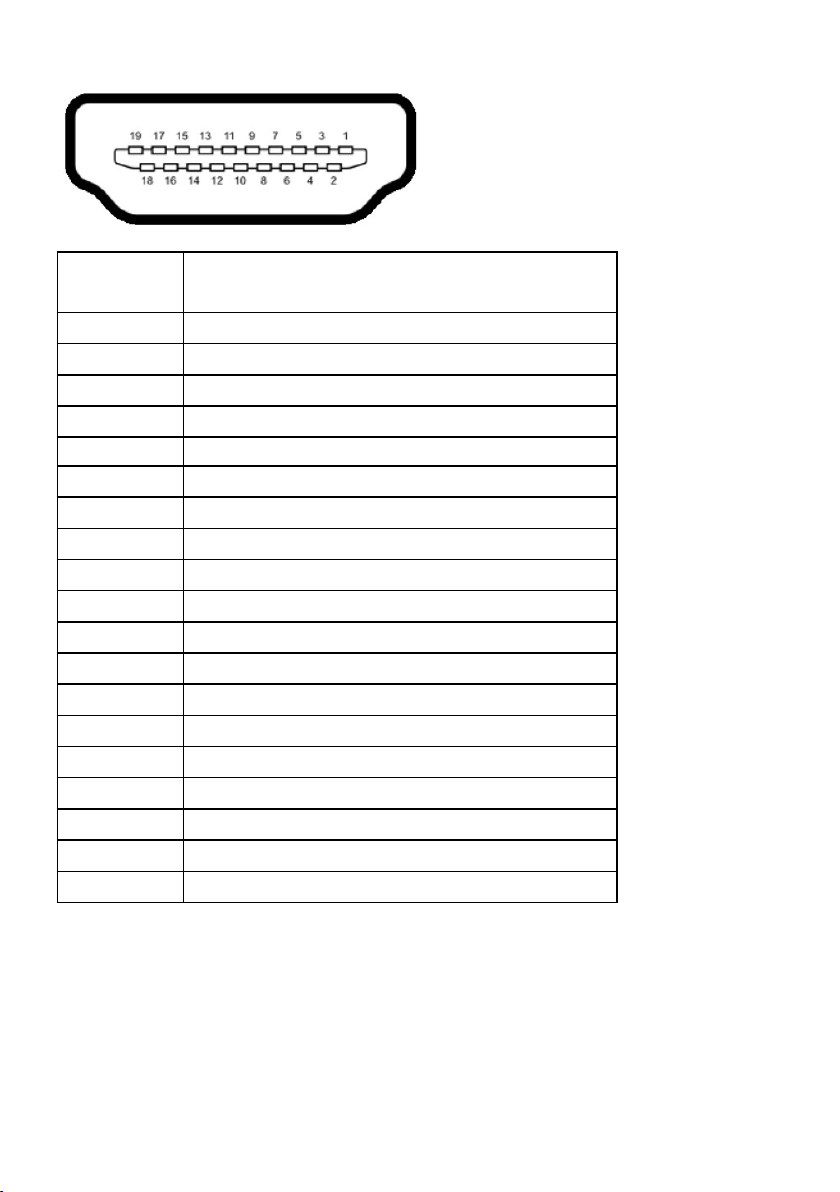
MHL Connector
Pin Number 19-pin Side of the Connected Signal Cable
1 TMDS DATA 2+
2 TMDS DATA 2 SHIELD
3 TMDS DATA 24 TMDS DATA 1+
5 GND
6 TMDS DATA 17 MHL+
8 TMDS DATA 0 SHIELD
9 MHL-
10 TMDS CLOCK+
11 GND
12 TMDS CLOCK13 CEC
14 Reserved (N.C. on device)
15 DDC CLOCK (SCL)
16 DDC DATA (SDA)
17 GND
18 VBUS (+5V, 900mA maximum)
19 CBUS
About Your Monitor 19
Page 20
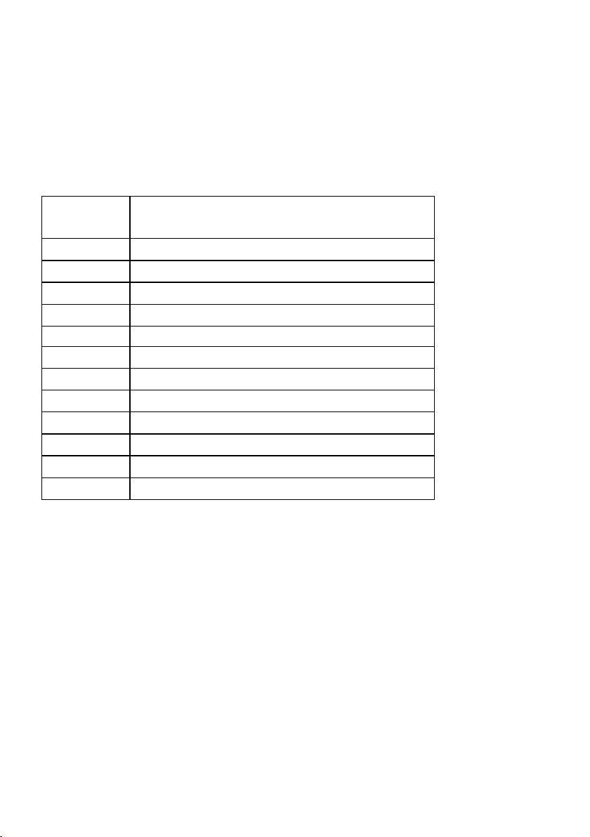
RJ-45 Connector
Pin Number 12-pin Side of the Connector
1 D+
2 RCT
3 D-
4 D+
5 RCT
6 D-
7 GND
8 GND
9 LED2_Y+
10 LED2_Y-
11 LED1_G+
12 LED1_G-
20 About Your Monitor
Page 21
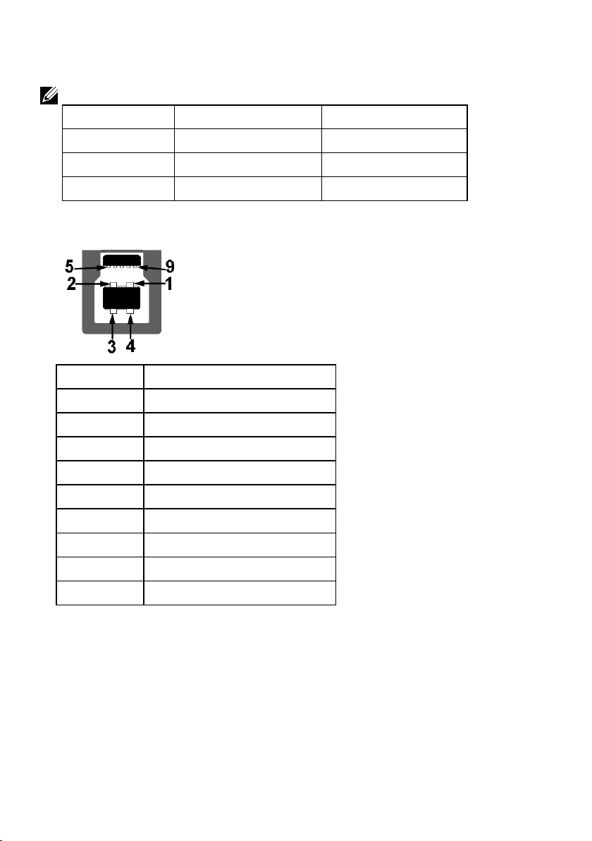
Universal Serial Bus (USB) Interface
This section gives you information about the USB ports that are available on the monitor.
NOTE : This monitor is Super-Speed USB 3.0 compatible.
Transfer Speed Data Rate Power Consumption
Super-Speed 5 Gbps 4.5W (Max, each port)
High Speed 480 Mbps 4.5W (Max, each port)
Full Speed 12 Mbps 4.5W (Max, each port)
USB Upstream Connector
Pin Number 9-pin Side of the Connector
1 VCC
2 D-
3 D+
4 GND
5 SSTX-
6 SSTX+
7 GND
8 SSRX-
9 SSRX+
About Your Monitor 21
Page 22

USB Downstream Connector
Pin Number 9-pin Side of the Connector
1 VCC
2 D3 D+
4 GND
5 SSTX6 SSTX+
7 GND
8 SSRX9 SSRX+
USB Ports
• 1 upstream
• 3 downstream
• 1 Dedicated Charging Port (DCP) - DCP port is for charging devices and has no
data lines.
NOTE: USB 3.0 functionality requires a USB 3.0-capable computer.
NOTE: The monitor’s USB interface works only when the monitor is On or in
the power-save mode. If you turn Off the monitor and then turn it On, the
attached peripherals may take a few seconds to resume normal functionality.
22 About Your Monitor
Page 23

Plug and Play Capability
You can install the monitor in any Plug and Play compatible system. The monitor
automatically provides the computer with its Extended Display Identification Data (EDID)
using Display Data Channel (DDC) protocols so that the system can configure itself and
optimize the monitor settings. Most monitor installations are automatic. You can select
different settings if required.
Flat-Panel Specifications
Model number C7017T
Screen type Active matrix - TFT LCD
Panel Type Vertical Alignment
Viewable image
Diagonal 1765.63 mm (69.513 inches)
Horizontal Active Area
Vertical Active Area 865.62 mm (34.08 inches)
Active Area 1332085.31 mm
Pixel pitch 0.802 x 0.802 mm
Viewing angle:
Horizontal 176° typical
Vertical 176° typical
Luminance output 380 cd/m² (typical)
Contrast ratio 3800 to 1 (typical)
Faceplate coating Antiglare with hard-coating 2H
Backlight LED light bar system
Response Time 8 ms typical (gray to gray)
Color Depth 1.07 billion colors
Color Gamut 86 % (typical) *
* C7017T color gamut (typical) is based on CIE1976 (86 %) and CIE1931 (72 %) test
standards.
1538.88 mm (60.59 inches)
2
(2064.91 inches2)
About Your Monitor 23
Page 24

Touch Specifications
Model number C7017T
Type Infrared Touch
Panel Diagonal 69.58 inch
Active Area Extended beyond Viewing Area
Touch Input Method Finger, Passive Stylus
Max number of multi-touch 10 points
Touch Accuracy ≤ 2 mm (Over 90% of screen)
Touch Response Time ≤ 15 ms
Windows XP, Vista, 7, 8, 8.1, 10,
Operating system
Glass Surface Anti-Glare, Anti-Smudge, Hardness (5H)
Glass Thickness 4 mm
NOTE: Windows XP, Vista, Mac OS are Single Touch.
Chrome OS, Android, Linux
Mac OS, iOS
Touch OS Compatibility
OS Version Touch Points
XP
Vista
7 home basic
Windows
Chrome ver 38 and above Multi Touch
Mac
Android Kernel version 3.0 and above Multi Touch
7 (Ultimate, Professional, Home Premium)
8 (Pro, Enterprise) (Non-OEM version)
8.0 / 8.1(Pro, Enterprise) (Non-OEM version)
10 (Home, Professional, Enterprise,
Educaiton, Non-OEM only)
Ver 10.11 and above
Ver 10.6 - 10.10
Below Ver 10.6
Single Touch
Multi Touch
Single Touch
24 About Your Monitor
Page 25

Resolution Specifications
Model number C7017T
Scan range
• Horizontal 30 kHz to 83 kHz (automatic)
• Vertical 23 Hz to 120 Hz (automatic)
Maximum preset
resolution
1920 x 1080 at 60 Hz
Electrical Specifications
Model number C7017T
Video input signals • Analog RGB: 0.7 Volts ± 5 %, 75 ohm input impedance
• DisplayPort, 600mV for each differential line, 100 ohm input
impedance per differential pair
• HDMI (MHL), 600mV for each differential line, 100 ohm
input impedance per differential pair
Synchronization input
signals
AC input voltage /
frequency / current
Inrush current 120 V: 40 A (Max.)
Separate horizontal and vertical synchronizations, polarity-free
TTL level, SOG (Composite SYNC on green)
100 VAC to 240 VAC / 50 Hz or 60 Hz ± 3 Hz / 4.0 A (Max)
240 V: 80 A (Max.)
Preset Display Modes
The following table lists the preset modes for which Dell guarantees image size and
centering:
Horizontal
Display Mode
Frequency
(kHz)
VESA, 720 x 400 31.5 70.8 28.3 -/+
VESA, 640 x 480 31.5 59.9 25.2 -/-
VESA, 640 x 480 37.5 75.0 31.5 -/-
VESA, 800 x 600 37.9 60.3 40.0 +/+
VESA, 800 x 600 46.9 75.0 49.5 +/+
VESA, 1024 x 768 48.4 60.0 65.0 -/-
VESA, 1024 x 768 60.0 75.0 78.8 +/+
VESA, 1152 x 864 67.5 75.0 108.0 +/+
Vertical
Frequency
(Hz)
Pixel Clock
(MHz)
Sync Polarity
(Horizontal/
Vertical)
About Your Monitor 25
Page 26

VESA, 1280 x 1024 64.0 60.0 108.0 +/+
VESA, 1280 x 1024 80.0 75.0 135.0 +/+
VESA, 1600 x 900 60.0 60.0 108.0 +/+
VESA, 1920 x 1080 67.5 60.0 148.5 +/+
MHL Source Display Modes
Display Mode Frequency (Hz)
640 x 480 p 59.94
720 x 480 p 59.94
720 x 576p 50
1280 x 720p 60
1280 x 720p 50
1920 x 1080i 60
1920 x 1080i 50
1920 x 1080p 30
720 (1440) x 480i 60
720 (1440) x 576i 50
Physical Characteristics
The following table lists the monitor's physical characteristics:
Model Number C7017T
Connector type 15-pin D-subminiature (Black connector)
DP, Black connector
HDMI (MHL)
Signal cable type VGA
DisplayPort
HDMI (MHL)
Dimensions:
Height 932.61 mm (36.72 inches)
Width 1593.5 mm (62.74 inches)
Depth 95.1 mm (3.74 inches)
26 About Your Monitor
Page 27

Weight:
Weight with packaging 78.6 kg (173.28 lb)
Weight (For wall
mount or VESA mount
considerations - no
cables)
55.5 kg (122.36 lb)
Environmental Characteristics
The following table lists the environmental conditions for your monitor:
Model Number C7017T
Temperature
• Operating
• Non-operating
Humidity
• Operating
• Non-operating
Altitude
• Operating
• Non-operating
Thermal dissipation 784.99 BTU/hour (maximum)
0 °C to 40 °C (32 °F to 104 °F)
Storage: -20 °C to 60 °C (-4 °F to 140 °F)
Shipping: -20 °C to 60 °C (-4 °F to 140 °F)
10 % to 80 % (non-condensing)
Storage: 5 % to 90 % (non-condensing)
Shipping: 5 % to 90 % (non-condensing)
5,000 m (16,404 ft) max
12,191 m (40,000 ft) max
495.89 BTU/hour (typical)
LCD Monitor Quality & Pixel Policy
During the LCD Monitor manufacturing process, it is not uncommon for one or more
pixels to become fixed in an unchanging state. The visible result is a fixed pixel that
appears as an extremely tiny dark or bright discolored spot. When the pixel remains
permanently lit, it is known as a “bright dot.” When the pixel remains black, it is known
as a “dark dot.”
In almost every case, these fixed pixels are hard to see and do not detract from display
quality or usability. A display with 1 to 5 fixed pixels is considered normal and within
competitive standards. For more information, see Dell Support site at:
http://www.dell.com/support/monitors.
About Your Monitor 27
Page 28

Maintenance Guidelines
Caring for Your Monitor
CAUTION: Read and follow the safety instructions before cleaning the
monitor.
CAUTION: Before cleaning the monitor, unplug the monitor power
cable from the electrical outlet.
For best practices, follow the instructions in the list below while unpacking, cleaning, or
handling your monitor:
• To clean your antistatic screen, slightly dampen a soft, clean cloth with water. If
possible, use a special screen-cleaning tissue or solution suitable for the antistatic
coating. Do not use benzene, thinner, ammonia, abrasive cleaners, or compressed
air.
• Use a slightly dampened, warm cloth to clean the plastics. Avoid using detergent of
any kind as some detergents leave a milky film on the plastics.
• If you notice a white powder when you unpack your monitor, wipe it off with a
cloth. This white powder occurs during the shipping of the monitor.
• Handle your monitor with care as a darker-colored monitor may scratch and show
white scuff marks more than a lighter-colored monitor.
• To help maintain the best image quality on your monitor, use a dynamically
changing screen saver and power off your monitor when not in use.
28 About Your Monitor
Page 29

Setting Up the Monitor
Connecting Your Monitor
WARNING: Before you begin any of the procedures in this section, follow
the Safety Instructions.
To connect your monitor to the computer:
1. Turn o your computer and disconnect the power cable.
2. Connect the VGA / DP / HDMI / MHL cable to the corresponding video
port on the back of your computer.
Connecting VGA Cable
Connecting DP Cable
Setting Up the Monitor 29
Page 30

Connecting HDMI cable
Connecting MHL cable
30 Setting Up the Monitor
Page 31

Connecting USB cable
After you have completed connecting the VGA / DP / HDMI / MHL cable, follow
the procedures below to connect the USB cable to the computer and complete
your monitor setup:
1. Connect the upstream USB port (cable supplied) to an appropriate USB
port on your computer. (See Side view for details.)
2. Connect the USB peripherals to the downstream USB ports on the
monitor.
3. Plug the power cables for your computer and monitor into a nearby
outlet.
4. Turn on the monitor and the computer. If your monitor displays an image,
installation is complete. If it does not display an image, see Solving
Problems.
NOTE: The graphics are used for the purpose of illustration only. Appearance on the
computer may vary.
Setting Up the Monitor 31
Page 32

Wall Mounting
(Screw dimension: M8 x 20 ~ 30 mm).
Refer INSTALLATION INSTRUCTIONS to that come with LSA1U Wall Mount
kit and the VESA-compatible base mounting kit (400 x 400 mm distance).
1. Install Wall Plate to Wall.
2. Place the monitor panel on a soft cloth or cushion on a stable flat table
3. Attach the mounting brackets from the wall mounting kit to the monitor.
4. Install Display to Wall Plate.
For more information, see the Wall Mount provider website located at
http://www.milestone.com/~/media/Files/Chief/Manuals/MSA1U_MTA1U_
LSA1U_LTA1U-I.pdf
.
32 Setting Up the Monitor
Page 33

Operating the Monitor
Power On the Monitor
Press the button to turn on the monitor.
Using the Front-Panel Controls
Use the keys on the front of the monitor to adjust the image settings.
Front-Panel Keys Description
A
Preset modes
B
Volume
C
Menu
D
Exit
Use the Preset modes key to choose from a list of
preset color modes. See Using the OSD Menu.
Use the Volume key to direct access to the "Volume"
control menu.
Use the Menu key to open the on-screen display
(OSD).
Use the Exit key to exit on-screen display (OSD)
from menu and sub-menus.
Front-Panel Keys
Front-Panel Keys Description
A
Up
Use the Up key to adjust (increase ranges) items in the OSD
menu.
Operating the Monitor 33
Page 34

B
Use the Down key to adjust (decrease ranges) items in the
OSD menu.
Down
C
Use the OK key to confirm your selection.
OK
D
Back
Use the Back key to go back to the previous menu.
Using the On-Screen Display (OSD) Menu
Accessing the Menu System
NOTE: If you change the settings and then either proceed to another menu or exit
the OSD menu, the monitor automatically saves those changes. The changes are
also saved if you change the settings and then wait for the OSD menu to disappear.
1. Press the button to open the OSD menu and display the main menu.
Main Menu
NOTE: Auto Adjust is only available when you use the analog (VGA) connector.
34 Operating the Monitor
Page 35

2. Press the
and buttons to toggle between options in the Menu. As
you move from one icon to another, the option name is highlighted.
3. To select the highlighted item on the menu press the
4. Press the
5. Press the
and buttons to select the desired parameter.
button to enter the slide bar and then use the or
button again.
buttons, according to the indicators on the menu, to make your changes.
6. Select the
to return to previous menu without accepting current
settings or to accept and return to previous menu.
The table below provides a list of all the OSD menu options and their functions.
Icon Menu and
Submenus
Energy Use This meter shows the energy level being consumed by the
Brightness/
Contrast
Description
monitor in real time.
Use the Brightness/Contrast menu to adjust the Brightness/
Contrast.
Brightness
Contrast
Allows you to adjust the brightness or luminance of the
backlight.
Press the
decrease brightness (min 0 ~ max 100).
Allows you to adjust the contrast or the degree of difference
between darkness and lightness on the monitor screen. Adjust
brightness first, and adjust contrast only if you need further
adjustment.
Press the
decrease contrast (min 0 ~ max 100).
key to increase brightness and press the key to
key to increase contrast and press the key to
Operating the Monitor 35
Page 36

Auto Adjust Use this key to activate automatic setup and adjust menu.
The following dialog appears on a black screen as the monitor
self-adjusts to the current input:
Auto Adjustment allows the monitor to self-adjust to the
incoming video signal. After using Auto Adjustment, you can
further tune your monitor by using the Pixel Clock (Coarse) and
Phase (Fine) controls under Display.
NOTE: Auto Adjust does not occur if you press the button while
there are no active video input signals or attached cables.
This option is only available when you are using the analog
(VGA) connector.
36 Operating the Monitor
Page 37

Input Source Use the Input Source menu to select between different video
signals that may be connected to your monitor.
VGA
DP
HDMI1/MHL
HDMI2
HDMI3
Auto Select
Reset Input
Source
Select VGA input when you are using the analog (VGA)
connector. Push
to select the VGA input source.
Select DP input when you are using the DP connector. Push
to select the DP input source.
Select HDMI1/MHL input when you are using the HDMI1/MHL
connector. Push
to select the HDMI1/MHL input source.
Select HDMI2 or HDMI3 input when you are using the HDMI2 or
HDMI3 connector. Push
to select the HDMI2 or HDMI3 input
source.
Select Auto Select to scan for available input signals.
Resets your monitor’s Input Source settings to the factory
defaults.
Operating the Monitor 37
Page 38

Color Use the Color menu to adjust the monitor's color settings.
Input Color
Format
Allows you to set the video input mode to:
• RGB: Select this option if your monitor is connected to
a computer or DVD player using the DP adapter.
• YPbPr: Select this option if your DVD player supports
only YPbPr output.
38 Operating the Monitor
Page 39

Preset Modes
Reset Color
Allows you to choose from a list of preset color modes.
• Standard: Loads the monitor's default color settings.
This is the default preset mode.
• Warm: Increases the color temperature. The screen
appears warmer with a red/yellow tint.
• Custom Color: Allows you to manually adjust the color
settings. Press the
Green, and Blue values and create your own preset
color mode.
Resets your monitor's color settings to the factory defaults.
and
keys to adjust the Red,
Operating the Monitor 39
Page 40

Display Use the Display menu to adjust the monitor's display settings.
Aspect Ratio
Horizontal
Position
Vertical Position
Sharpness
Pixel Clock
Phase
Response Time
Reset Display
Adjusts the image ratio as Wide 16:9, 4:3, or 5:4.
NOTE: Wide 16:9 adjustment is not required at maximum preset
resolution 1920 x 1080 .
Use or the buttons to adjust image left and right. Minimum
is '0' (-). Maximum is '100' (+).
Use the or buttons to adjust image up and down. Minimum
is '0' (-). Maximum is '100' (+).
NOTE: Horizontal Position and Vertical Position adjustments are
only available for “VGA” input.
This feature can make the image look sharper or softer. Use
or
to adjust the sharpness from '0' to '100'.
The Phase and Pixel Clock adjustments allow you to adjust your
monitor to your preference. Use
or buttons to adjust for
best image quality.
If satisfactory results are not obtained using the Phase
adjustment, use the Pixel Clock (coarse) adjustment and then use
Phase (fine), again.
NOTE: Pixel Clock and Phase adjustment are only available for
VGA input.
Allows you to set the Response Time to Normal or Fast.
NOTE:
Normal (G to G typical /Ave.) : 8 ms
Fast (G to G typical /Ave.) : 6 ms
Select this option to restore default display settings.
40 Operating the Monitor
Page 41

Audio
Volume
Audio Source
Speaker
Reset Audio
Use the buttons to adjust the volume. Minimum is ‘0’ (-).
Maximum is ‘100’ (+).
Allows you to set the Audio Source mode to:
•PCAudio
•HDMI/DP
Allows you to enable or disable Speaker function.
Select this option to restore default display settings.
Operating the Monitor 41
Page 42

Energy
Power Button
LED
USB
Reset Energy
Allows you to set the power LED indicator on or off during active
to save energy.
Allows you to enable or disable USB function during monitor
standby mode.
NOTE: USB ON/OFF under standby mode is only available when
USB upstream cable is unplugged. This option will be greyed out
when USB upstream cable is plugged in.
Select this option to restore default Energy settings.
42 Operating the Monitor
Page 43

Menu Select this option to adjust the settings of the OSD such as, the
languages of the OSD, the amount of time the menu remains on
screen, and so on.
Language
Transparency
Timer
Lock
Reset Menu
Allows you to set the OSD display to one of eight languages:
English, Spanish, French, German, Brazilian Portuguese, Russian,
Simplified Chinese, or Japanese.
Allows you to adjust the OSD background from opaque to
transparent.
Allows you to set the time for which the OSD remains active
after you press a key on the monitor.
Use the
and keys to adjust the slider in 1 second
increments, from 5 to 60 seconds.
Controls user access to adjustments. When Lock is selected, no
user adjustments are allowed. All keys are locked except
key.
To unlock, please use one of the following options :
1. Press the menu key of remote control takes you directly to
the OSD menu to unlock.
2. Press and hold
key of the monitor for 6 seconds to
unlock.
Warning:
1. During lock, OSD & power key will lock.
2. The power button and OSD keys must be unlocked when it
is required to power off the monitor.
Select this option to restore default menu settings.
Operating the Monitor 43
Page 44

Personalize Selecting this option allows you to set two shortcut keys.
Shortcut Key 1
User can select from "Preset Modes", "Brightness/Contrast",
"Auto Adjust", "Input Source", "Aspect Ratio" “Volume” and set as
shortcut key.
44 Operating the Monitor
Page 45

Shortcut Key 2
User can select from "Preset Modes", "Brightness/Contrast",
"Auto Adjust", "Input Source" , "Aspect Ratio" , “Volume” and set as
shortcut key.
Reset
Personalization
Others
Allows you to restore shortcut key to the default setting.
Operating the Monitor 45
Page 46

DDC/CI
DDC/CI (Display Data Channel/Command Interface) allows a
software on your computer to adjust the monitor display settings
like the brightness, color balance etc.
Enable (Default): Optimizes the performance of your monitor
and provides a better customer experience.
Disable: Disables the DDC/CI option and the following message
appears on the screen.
LCD
Conditioning
Firmware
IP Address
Reset Other
Factory Reset
This feature will help reduce minor cases of image retention.
If an image appears to be stuck on the monitor, select LCD
Conditioning to help eliminate any image retention. Using
the LCD Conditioning feature may take some time. LCD
Conditioning feature cannot remove severe cases of image
retention or burn-in.
NOTE: Use LCD Conditioning only when you experience a
problem with image retention.
The below warning message appears once user selects “Enable"
LCD Conditioning.
Current Firmware version.
Shown IP Address.
Select this option to restore default other settings, such as DDC/
CI.
Resets all OSD settings to the factory preset values.
46 Operating the Monitor
Page 47

OSD Messages
When the monitor does not support a particular resolution mode you will see the
following message:
This means that the monitor cannot synchronize with the signal that it is receiving from
the computer. See Monitor Specifications for the horizontal and vertical frequency
ranges addressable by this monitor. Recommended mode is 1920 x 1080.
You will see the following message before the DDC/CI function is disabled.
When the monitor enters the Power Save mode, the following message appears:
Activate the computer and wake up the monitor to gain access to the OSD.
Operating the Monitor 47
Page 48

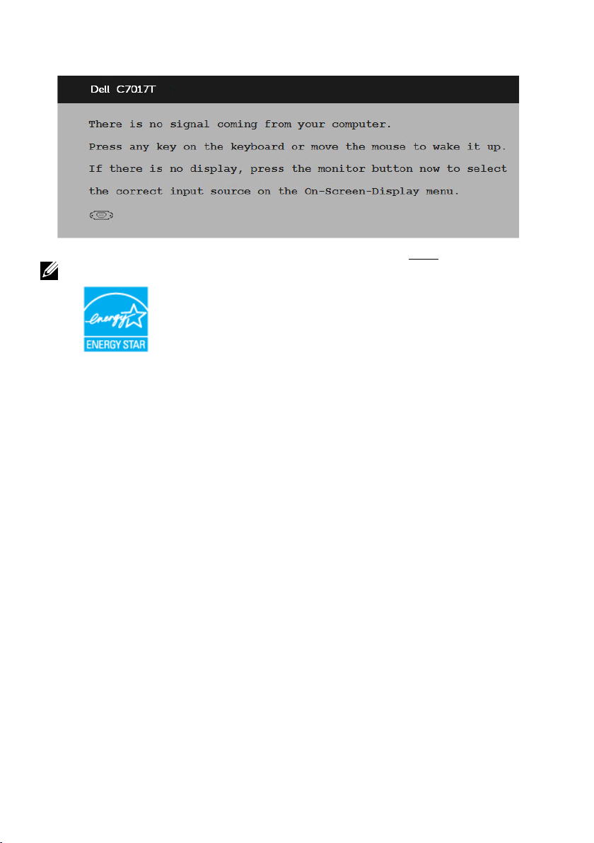
If you press any button other than the power button, the following messages will appear
depending on the selected input:
If VGA, DP, HDMI1/MHL, HDMI2 or HDMI3 cable is not connected, a floating dialog box
as shown below appears. The monitor will enter Power Save Mode after 4 minutes if left
at this state.
48 Operating the Monitor
Page 49

See Solving Problems for more information.
Operating the Monitor 49
Page 50

Setting the Maximum Resolution
For optimal display performance while using the Microsoft Windows operating systems,
set the display resolution to 1920 x 1080 pixels by performing the following steps:
In Windows Vista, Windows 7, Windows 8 or Windows 8.1:
1. For Windows 8 or Windows 8.1 only, select the Desktop tile to switch to classic
desktop.
2. Right-click on the desktop and click Screen Resolution.
3. Click the dropdown list of the screen resolution and select 1920 x 1080.
4. Click OK.
In Windows 10:
1. Right-click on the desktop and click Display settings.
2. Click Advanced display settings.
3. Click the dropdown list of Resolution and select 1920 x 1080.
4. Click Apply.
If you do not see 1920 x 1080 as an option, you may need to update your graphics
driver. Please choose the scenario below that best describes the computer system you
are using, and follow the provided
1: If you have a Dell desktop or a Dell portable computer with Internet access
2:If you have a non Dell desktop, portable computer, or graphics card
50 Operating the Monitor
Page 51

If you have a Dell desktop or a Dell portable computer
with Internet access
1. Go to http://www.dell.com/support, enter your service tag, and download the
latest driver for your graphics
2. After installing the drivers for your graphics adapter, attempt to set the resolution
to 1920 x 1080 again.
NOTE: If you are unable to set the resolution to 1920 x 1080, please contact
Dell to inquire about a graphics adapter that supports these resolutions.
If you have a non Dell desktop, portable computer, or
graphics card
In Windows Vista, Windows 7, Windows 8 or Windows 8.1:
1. For Windows 8 or Windows 8.1 only, select the Desktop tile to switch to classic
desktop.
2. Right-click on the desktop and click Personalization.
3. Click Change Display Settings.
4. Click Advanced Settings.
5. Identify your graphics controller supplier from the description at the top of the
window (e.g. NVIDIA, ATI, Intel etc.).
6. Please refer to the graphics card provider website for updated driver (for example,
http://www.ATI.com OR http://www.NVIDIA.com ).
7. After installing the drivers for your graphics adapter, attempt to set the resolution
to 1920 x 1080 again
In Windows 10:
1. Right-click on the desktop and click Display settings.
2. Click Advanced display settings.
3. Click Display adapter properties.
4. Identify your graphics controller supplier from the description at the top of the
window (e.g. NVIDIA, ATI, Intel etc.).
5. Please refer to the graphics card provider website for updated driver (for example,
http://www.ATI.com OR http://www.NVIDIA.com ).
6. After installing the drivers for your graphics adapter, attempt to set the resolution
to 1920 x 1080 again.
NOTE: If you are unable to set the resolution to 1920 x 1080, please contact
the manufacturer of your computer or consider purchasing a graphics adapter
that will support the video resolution of 1920 x 1080 .
.
Operating the Monitor 51
Page 52

Dell Web Management for Monitors
Before accessing the Dell Monitor Web Management feature, please refer to the
Ethernet Problems . Ensure the Ethernet is working normally.
To access the Dell Monitor Web Management tool you need to set the IP Addresses for
your computer and the monitor.
1. Press the Menu key on the remote control to display the IP Address of the monitor,
or by navigating to OSD Menu > Others. By default, the IP Address is 10.0.50.100
2. In the computer’s IP Properties tab, specify an IP Address by selecting Use
the following IP Address and enter the following values: For IP Address:
10.0.50.101 and for Subnet Mask: 255.0.0.0 (leave all other entries as blanks).
52 Operating the Monitor
Page 53

3. The IP Address configuration would now look like this:
To access and use the web management tool, follow these steps:
1. Open a web browser and type the monitor’s IP Address (10.0.50.100) in the
address bar.
Operating the Monitor 53
Page 54

2. The log-in page opens. Enter the Administrator Password to continue.
3. The Home page opens:
54 Operating the Monitor
Page 55

4. Click Network Settings tab to see the network settings.
Operating the Monitor 55
Page 56

5. Click Monitor Control to see the monitor’s status.
6. Click Security to set a password.
56 Operating the Monitor
Page 57

7. Update Firmware. You can download the latest drivers from the Dell
Support website at www.dell.com/support.
Operating the Monitor 57
Page 58

Troubleshooting
WARNING: Before you begin any of the procedures in this section, follow the
Safety Instruction
Self-Test
Your monitor provides a self-test feature that allows you to check whether your monitor
is functioning properly. If your monitor and computer are properly connected but the
monitor screen remains dark, run the monitor self-test by performing the following
steps:
1. Turn o both your computer and the monitor.
2. Unplug the video cables from the back of the computer. To ensure proper Self-
Test operation, remove all VGA, DP, HDMI1 /MHL, HDMI2, HDMI3 cables from the
back of computer.
3. Turn on the monitor.
The floating dialog box should appear on-screen (against a black background) if
the monitor cannot sense a video signal and is working correctly. While in selftest mode, the power LED remains white. Also, depending upon the selected
input, one of the dialogs shown below will continuously scroll through the screen.
4. This box also appears during normal system operation, if the video cable becomes
disconnected or damaged. The monitor will enter Power Save Mode after 4
minutes if left at this state.
5. Turn o your monitor and reconnect the video cable; then turn on both your
computer and the monitor.
If your monitor screen remains blank after you use the previous procedure, check your
video controller and computer, because your monitor is functioning properly.
58 Troubleshooting
Page 59

Built-in Diagnostics
Your monitor has a built-in diagnostic tool that helps you determine if the screen
abnormality you are experiencing is an inherent problem with your monitor, or with your
computer and video card.
NOTE: You can run the built-in diagnostics only when the video cable is unplugged
and the monitor is in self-test mode.
To run the built-in diagnostics:
1. Ensure that the screen is clean (no dust particles on the surface of the screen).
2. Unplug the video cable(s) from the back of the computer or monitor. The
monitor then goes into the self-test mode.
3. Press and hold the Button 1 on the front panel for 5 seconds. A gray screen
appears.
4. Carefully inspect the screen for abnormalities.
5. Press the Button 1 on the front panel again. The color of the screen changes
to red.
6. Inspect the display for any abnormalities.
7. Repeat steps 5 and 6 to inspect the display in green, blue, black, white screens.
The test is complete when the Text screen appears. To exit, press the Button 1 again.
If you do not detect any screen abnormalities upon using the built-in diagnostic tool,
the monitor is functioning properly. Check the video card and computer.
Troubleshooting 59
Page 60

Common Problems
The following table contains general information about common monitor problems you
might encounter and the possible solutions.
Common Symptoms What You
Experience
No Video/Power LED
off
No Video/Power LED onNo picture or no
Poor Focus Picture is fuzzy, blurry,
Shaky/Jittery Video Wavy picture or fine
No picture •Ensure that the video cable
brightness
or ghosting
movement
Possible Solutions
connecting the monitor and the
computer is properly connected and
secure.
•Verify that the power outlet is
functioning properly using any other
electrical equipment.
•Ensure that the power button is
depressed fully.
•Ensure that the correct input source
is selected via the Input Source Select
button.
•Check the “Power LED Button” option
under Energy in OSD Menu.
•Increase brightness & contrast
controls via OSD.
•Perform monitor self-test feature
check.
•Check for bent or broken pins in the
video cable connector.
•Ensure that the correct input source
is selected via the Input Source Select
menu.
•Run the built-in diagnostics.
•Perform Auto Adjust via OSD.
•Adjust the Phase and Pixel Clock
controls via OSD.
•Eliminate video extension cables.
•Reset the monitor to Factory
Settings.
•Change the video resolution to the
correct aspect ratio (16:9).
•Perform Auto Adjust via OSD.
•Adjust the Phase and Pixel Clock
controls via OSD.
•Reset the monitor to Factory
Settings.
•Check environmental factors.
•Relocate the monitor and test in
another room.
60 Troubleshooting
Page 61

Remote control no
working
Missing Pixels LCD screen has spots
Stuck-on Pixels LCD screen has bright
Brightness Problems Picture too dim or too
Geometric Distortion Screen not centered
Horizontal/Vertical
Lines
Cannot control LCD
Monitor
spots
bright
correctly
Screen has one or
more lines
•Check remote control batteries have
been installed property.
•Ensure the remote control sensor is
toward to monitor’s remote control
sensor on left bottom side.
•Cycle power on-o.
•Pixel that is permanently o is a
natural defect that can occur in LCD
technology.
For more information on Dell Monitor
Quality and Pixel Policy, see Dell
Support site at:
http://www.dell.com/support/
monitors.
•Cycle power on-o.
•Pixel that is permanently o is a
natural defect that can occur in LCD
technology.
For more information on Dell Monitor
Quality and Pixel Policy, see Dell
Support site at:
http://www.dell.com/support/
monitors.
•Reset the monitor to Factory
Settings.
•Auto Adjust via OSD.
•Adjust brightness & contrast controls
via OSD.
•Reset the monitor to Factory
Settings.
•Auto Adjust via OSD.
•Adjust brightness & contrast controls
via OSD.
•Reset the monitor to Factory
Settings.
•Perform Auto Adjust via OSD.
•Adjust Phase and Pixel Clock controls
via OSD.
•Perform monitor self-test feature
check and determine if these lines are
also in self-test mode.
•Check for bent or broken pins in the
video cable connector.
Troubleshooting 61
Page 62

Synchronization
Problems
Safety-Related Issues Visible signs of smoke
Intermittent Problems Monitor malfunctions
Missing Color Picture missing color •Perform monitor self-test feature
Wrong Color Picture color not good •Change the Color Mode in the Color
Image retention from
a static image left on
the monitor for a long
period of time
Screen is scrambled or
appears torn
or sparks
on & off
Faint shadow from the
static image displayed
appears on the screen
•Reset the monitor to Factory
Settings.
•Perform Auto Adjust via OSD.
•Adjust Phase and Pixel Clock controls
via OSD.
•Perform monitor self-test feature
check to determine if the scrambled
screen appears in self-test mode.
•Check for bent or broken pins in the
video cable connector.
•Restart the computer in the safe
mode.
•Do not perform any troubleshooting
steps.
•Contact Dell immediately.
•Ensure that the video cable
connecting the monitor to the
computer is connected properly and
is secure.
•Reset the monitor to Factory
Settings.
•Perform monitor self-test feature
check to determine if the intermittent
problem occurs in self-test mode.
check.
•Ensure that the video cable
connecting the monitor to the
computer is connected properly and
is secure.
•Check for bent or broken pins in the
video cable connector.
OSD to Graphics or Video depending
on the application.
•Try dierent Color Preset Settings
in Color OSD. Adjust R/G/B value in
Color OSD if the Color Management
is turned o.
•Change the Input Color Format to PC
RGB or YPbPr in the
•Use the Power Management
feature to turn o the monitor at
all times when not in use (for more
information, see Power Management
Modes.
•Alternatively, use a dynamically
changing screensaver.
Color OSD.
62 Troubleshooting
Page 63

NOTE: When choosing DP , HDMI1/MHL , HDMI2, HDMI3 mode, the Auto Adjust
function is not available.
Product-Specific Problems
Specific Symptoms What You
Experience
Screen image is too
small
Cannot adjust the
monitor with the
buttons on the front
panel
No Input Signal when
user controls are
pressed
The picture does not
fill the entire screen
Image is centered on
screen, but does not
fill entire viewing area
OSD does not appear
on the screen
No picture, the LED
light is white. When
you press “up”, “down”
or “Menu” key, the
message “ No input
signal” will appear.
The picture cannot fill
the height or width of
the screen
Possible Solutions
•Check the Aspect Ratio setting in the
Display OSD.
•Reset the monitor to Factory
Settings.
•Turn o the monitor, unplug the
power cord, plug back, and then turn
on the monitor.
•Check whether the OSD menu and
Power button is locked. If yes, press
and hold the button beside the Power
button for 6 seconds to unlock (for
more information, see Lock). Or
pressing the menu key of remote
control takes you directly to the
OSD settings menu, with OSD ‘Lock’
pre-selected on entry, use the
keys of remote control to select
‘Unlock’, press
to unlock. (for more information, see
Lock)
•Check the signal source. Ensure the
computer is not in the power saving
mode by moving the mouse or
pressing any key on the keyboard.
•Check whether the signal cable is
plugged in properly. Re-plug the
signal cable if necessary.
•Reset the computer or video player.
•Due to dierent video formats (aspect
ratio) of DVDs, the monitor may
display in full screen.
•Run the built-in diagnostics.
of remote control
and
Troubleshooting 63
Page 64

Universal Serial Bus (USB) Specific Problems
Common Symptoms What You
Experience
USB interface is not
working
High Speed USB 3.0
interface is slow.
USB peripherals are
not working
High Speed USB 3.0
peripherals working
slowly or not working
at all
Possible Solutions
•Check that your monitor is
turned ON.
•Reconnect the upstream cable
to your computer.
•Reconnect the USB peripherals
(downstream connector).
•Switch o and then turn on the
monitor again.
•Re-start the computer.
• Some USB devices like external
portable HDD require higher
electric current; connect the
device directly to the computer
system.
•Check that your computer is
USB 3.0-capable.
•Some computers have both
USB 3.0 and USB 2.0 and
USB 1.1 ports. Ensure that the
correct USB port is used.
•Reconnect the upstream cable
to your computer.
•Reconnect the USB peripherals
(downstream connector).
•Re-start the computer.
64 Troubleshooting
Page 65

Mobile High-Definition Link (MHL) Specific Problems
Common Symptoms What You
Experience
MHL interface is not
working.
Cannot see MHL
device image shown
on monitor.
Touch Problems
Common Symptoms What You
Experience
No touchscreen
response in saving
mode
Could not wake
up monitor and
computer by touching
the screen in saving
mode
Possible Solutions
•Re-connect the upstream cable
Ensure your MHL cable and MHL
device are MHL certified.
•Check your MHL device is turned
On.
•Check your MHL device is not in
Standby mode.
•Check physical MHL cable
connection is corresponding to
input source selected on OSD
Menu i.e., HDMI (MHL) .
•Wait for 30 seconds after
connecting MHL cable as some
MHL devices require longer
recovery time.
Possible Solutions
•Ensure that the USB cable
connecting to PC and the monitor
properly secured.
•Access Device Manager and
choose HID Interface Device under
Human Device.
•Select HID- compliant device
Properties.
•Allow the device to wake the
computer.
Troubleshooting 65
Page 66

Ethernet Problems
Common Symptoms What You
Experience
Ethernet not working Dell Web
Management for
Monitors Webpage
control is not working
Possible Solutions
•Ensure that the Network cable
connecting the Monitor is properly
secured.
•Press and hold the Button 1 and
Button 3 on the front panel for 3
seconds to turn on , A network
icon
Top - left corner for 5 seconds .
•Press and hold the Button 1 and
Button 3 on the front panel for 3
seconds to turn o , A network
icon
Top - left corner for 5 seconds .
appears and is shown on
appears and is shown on
66 Troubleshooting
Page 67

Appendix
Safety Instructions
WARNING: Use of controls, adjustments, or procedures other than those
specified in this documentation may result in exposure to shock, electrical
hazards, and/or mechanical hazards.
For information on safety instructions, see the Safety, Environmental, and Regulatory
Information.
FCC Notices (U.S. Only) and Other Regulatory Information
For FCC notices and other regulatory information, see the regulatory compliance
website located at www.dell.com\regulatory_compliance.
This device complies with Part 15 of the FCC Rules. Operation is subject to the
following two conditions:
(1) this device may not cause harmful interference
(2) this device must accept any interference received including interference that may
cause undesired operation
Contact Dell
For customers in the United States, call 800-WWW-DELL (800-999-3355).
NOTE: If you do not have an active Internet connection, you can find contact
information on your purchase invoice, packing slip, bill, or Dell product catalog.
Dell provides several online and telephone-based support and service options.
Availability varies by country and product, and some services
may not be available in your area.
To get online monitor support content:
1. Visit www.dell.com/support/monitors
2. To contact Dell for sales, technical support, or customer service issues:
1. Visit www.dell.com/contactdell.
2. Verify your country or region in the Choose A Country/Region drop-
down menu at the top left of the page.
3. Click Contact Us on the top left side of the page.
4. Select the appropriate service or support link based on your need.
5. Choose the method of contacting Dell that is convenient for you.
Appendix 67
 Loading...