

Dell C6420 Installation Manual

Dell EMC PowerEdge C6420
Installation and Service Manual
Reg ula tor y M ode l: E43 S S eries
Reg ula tor y T ype : E 43S 001
Apr il 202 1
Rev . A 14

Notes, cautions, and warnings
NOTE: A NOTE indicates important information that helps you make better use of your product.
CAUTION: A CAUTION indicates either potential damage to hardware or loss of data and tells you how to avoid
the problem.
WARNING: A WARNING indicates a potential for property damage, personal injury, or death.
© 2017 - 2021 Dell Inc. or its subsidiaries. All rights reserved . D ell , E MC, and other trademarks are trademarks of Dell Inc. or its subsidi ari es.
Other trademarks may be trademarks of their respective owners.

Contents
Chapter 1: Dell EMC PowerEdge C6420 overview.......................................................................... 6
Supported configurations.................................................................................................................................................. 6
Back view of the PowerEdge C6420 sled..................................................................................................................... 8
Network ports indicator codes.........................................................................................................................................9
Sled to hard drive mapping...............................................................................................................................................11
Expander zoning..................................................................................................................................................................11
Locating the Service Tag of your system.................................................................................................................... 13
System information label..................................................................................................................................................14
Chapter 2: Initial system setup and configuration........................................................................ 17
Setting up your system.....................................................................................................................................................17
iDRAC configuration.......................................................................................................................................................... 17
Options to set up iDRAC IP address........................................................................................................................17
Log in to iDRAC............................................................................................................................................................ 18
Options to install the operating system........................................................................................................................18
Methods to download firmware and drivers..........................................................................................................18
Downloading drivers and firmware...........................................................................................................................19
Chapter 3: Installing and removing enclosure components.......................................................... 20
Safety instructions............................................................................................................................................................20
Before working inside your system............................................................................................................................... 20
After working inside your system...................................................................................................................................21
Recommended tools.......................................................................................................................................................... 21
Dell EMC PowerEdge C6420 sled..................................................................................................................................21
Sled Installation Guidelines.........................................................................................................................................21
Removing a sled ..........................................................................................................................................................22
Installing a sled ............................................................................................................................................................24
PERC battery..................................................................................................................................................................... 26
Removing the PERC battery.................................................................................................................................... 26
Installing the PERC battery....................................................................................................................................... 27
Air shroud............................................................................................................................................................................ 28
Removing the air shroud............................................................................................................................................28
Installing the air shroud .............................................................................................................................................29
System memory................................................................................................................................................................. 30
System memory guidelines........................................................................................................................................ 30
General memory module installation guidelines.....................................................................................................31
Removing a memory module..................................................................................................................................... 33
Installing a memory module....................................................................................................................................... 34
Support bracket.................................................................................................................................................................35
Removing the support bracket................................................................................................................................ 35
Installing the support bracket...................................................................................................................................36
Linking board and PCIe cable......................................................................................................................................... 37
Removing the linking board and PCIe cables........................................................................................................ 37
Installing the linking board and PCIe cables.......................................................................................................... 38
Contents 3

Processor and heat sink module....................................................................................................................................39
Removing a processor and heat sink module....................................................................................................... 40
Installing a processor and heat sink module.......................................................................................................... 41
Removing the fabric processor from the processor heat sink module...........................................................43
Installing the fabric processor into the processor heat sink module.............................................................. 44
Removing the non-fabric processor from the processor and heat sink module..........................................46
Installing the non-fabric processor into a processor and heat sink module..................................................49
Removing the fabric and sideband cables..............................................................................................................51
Installing the fabric and sideband cables............................................................................................................... 52
Expansion cards.................................................................................................................................................................53
PCIe slot priority .........................................................................................................................................................53
Removing the expansion card riser assembly.......................................................................................................56
Installing the expansion card riser assembly......................................................................................................... 56
Removing an expansion card.................................................................................................................................... 57
Installing an expansion card...................................................................................................................................... 59
Removing the riser card............................................................................................................................................ 60
Installing the riser card................................................................................................................................................61
Removing the M.2 SATA x16 riser...........................................................................................................................62
Installing the M.2 SATA x16 riser.............................................................................................................................63
Removing the M.2 SATA card.................................................................................................................................. 64
Installing the M.2 SATA card....................................................................................................................................65
M.2 SSD module................................................................................................................................................................ 66
Removing the M.2 SATA x16 riser...........................................................................................................................67
Installing the M.2 SATA x16 riser............................................................................................................................. 67
Removing the M.2 SATA card.................................................................................................................................. 68
Installing the M.2 SATA card.................................................................................................................................... 69
Mezzanine and OCP cards...............................................................................................................................................71
Removing a mezzanine card...................................................................................................................................... 71
Installing a mezzanine card....................................................................................................................................... 72
Removing the mezzanine card bridge board ....................................................................................................... 73
Installing the mezzanine card bridge board........................................................................................................... 74
Removing the OCP card............................................................................................................................................ 75
Installing the OCP card.............................................................................................................................................. 75
System battery...................................................................................................................................................................76
Replacing system battery.......................................................................................................................................... 76
Installing the system battery.....................................................................................................................................77
System board......................................................................................................................................................................78
Removing the system board..................................................................................................................................... 78
Installing system board ..............................................................................................................................................79
Trusted Platform Module................................................................................................................................................. 81
Upgrading the Trusted Platform Module................................................................................................................81
Initializing TPM for BitLocker users........................................................................................................................ 82
Initializing the TPM 1.2 for TXT users.................................................................................................................... 83
Initializing the TPM 2.0 for TXT users................................................................................................................... 83
Chapter 4: System diagnostics.................................................................................................... 84
Dell Embedded System Diagnostics..............................................................................................................................84
Running the Embedded System Diagnostics from Boot Manager.................................................................. 84
Running the Embedded System Diagnostics from the Dell Lifecycle Controller......................................... 84
System diagnostic controls....................................................................................................................................... 84
4
Contents

Chapter 5: Jumpers and connectors ........................................................................................... 86
System board jumper settings....................................................................................................................................... 86
System board connectors............................................................................................................................................... 86
Disabling forgotten password.........................................................................................................................................87
Chapter 6: Getting help............................................................................................................... 88
Contacting Dell EMC........................................................................................................................................................ 88
Documentation feedback................................................................................................................................................ 88
Accessing system information by using QRL............................................................................................................. 88
Quick Resource Locator for C6400 and C6420 systems.................................................................................. 89
Receiving automated support with SupportAssist .................................................................................................. 89
Recycling or End-of-Life service information............................................................................................................ 89
Chapter 7: Documentation resources...........................................................................................90
Contents 5

Dell EMC PowerEdge C6420 overview
The PowerEdge C6420 sled supports up to two Intel Xeon Scalable processors with 28 cores per processor. The sled also
supports dedicated mezzanine, PCIe and Open Compute Project (OCP) adapters for expansion and connectivity.
NOTE: The Intel Xeon Scalable processor with fabric connector is also known as Native Omnipath.
Topics:
• Supported configurations
• Back view of the PowerEdge C6420 sled
• Network ports indicator codes
• Sled to hard drive mapping
• Expander zoning
• Locating the Service Tag of your system
• System information label
Supported configurations
1
The PowerEdge C6420 system supports the following configurations:
6 Dell EMC PowerEdge C6420 overview
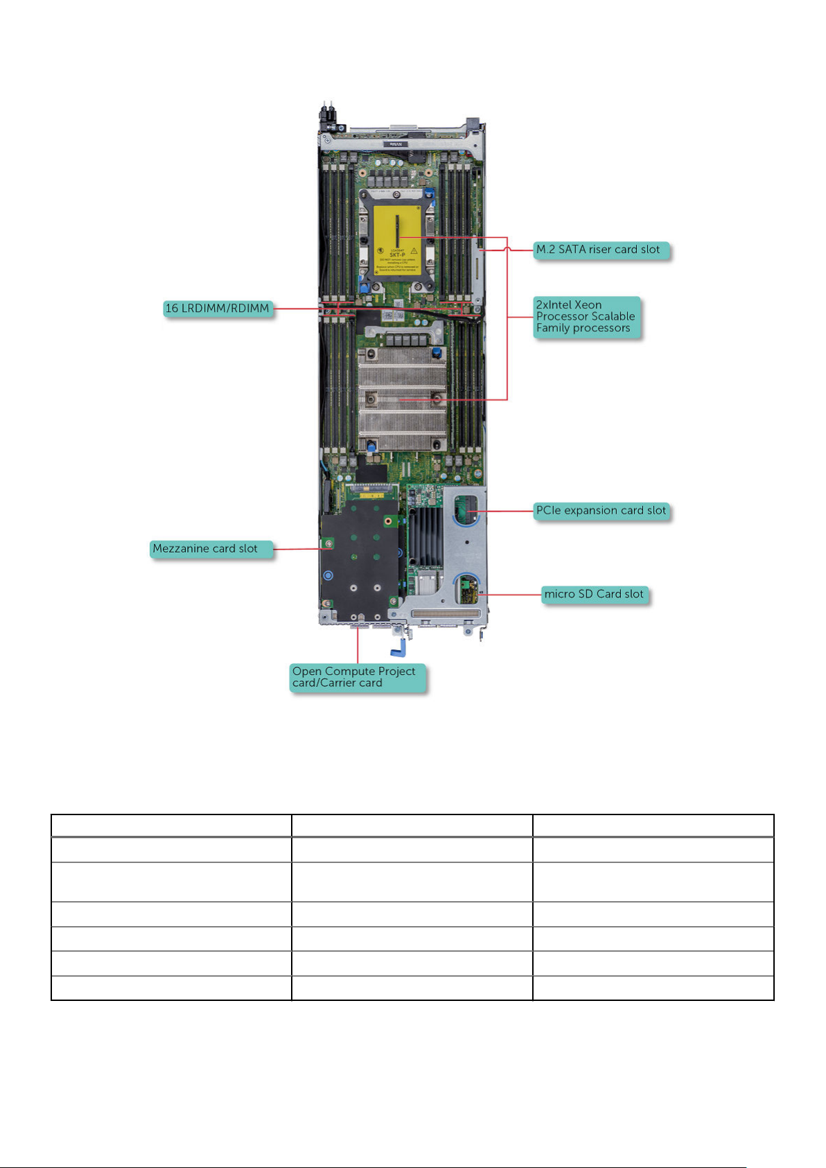
Figure 1. Supported configurations for PowerEdge C6420
Chassis configuration summary table
Table 1. Chassis configuration summary table
PE C6400 Chassis Config. PEC6420 support PEC6525 support
24 x 2.5" SAS/SATA Backplane Yes Yes
8 x 2.5" NVME + 16 X 2.5" SAS/SATA
backplane
12 x 3.5" SAS/SATA Backplane Yes Yes
Diskless No backplane Yes Yes
Expander Backplane Yes No
24 x 2.5" All/PURE NVME backplane No Yes
Yes Yes
Dell EMC PowerEdge C6420 overview 7
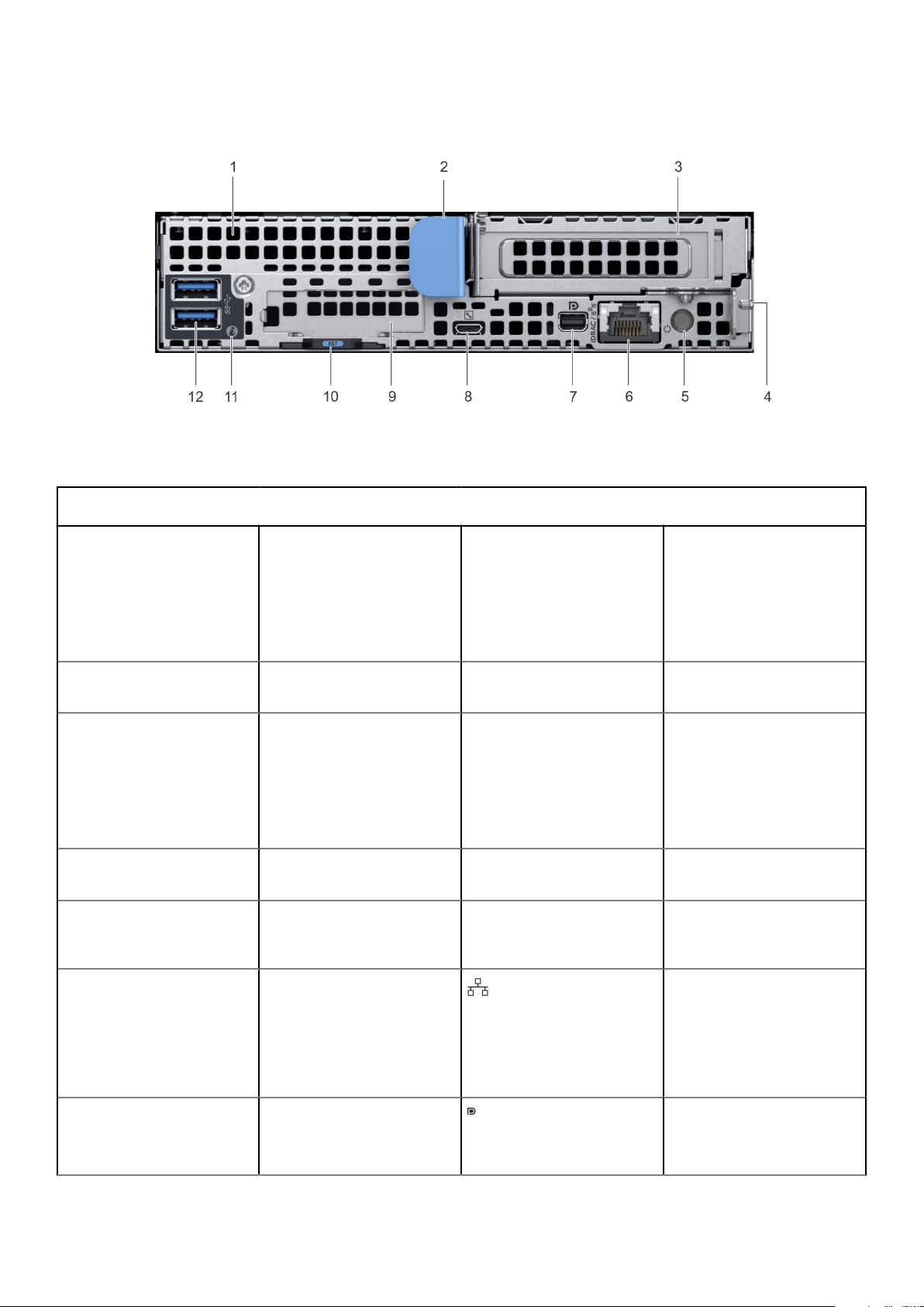
Back view of the PowerEdge C6420 sled
Figure 2. Back view of the PowerEdge C6420 sled
Table 2. Back panel features (continued)
Item Indicator, button, or
connector
1 Mezzanine card slot N/A
2 Sled release handle N/A
3 Low Profile PCIe card slot N/A
4 Sled release lock N/A
5 Rear power button N/A
Icon Description
Enables you to connect
mezzanine expansion cards.
For more information, see the
Dell EMC PowerEdge C6420
Technical Specifications on
the product documentation
page.
Enables you to remove the
sled from the enclosure.
Enables you to connect PCI
Express expansion cards. For
more information, see the
Dell EMC PowerEdge C6420
Technical Specifications on
the product documentation
page.
Enables you to remove the
sled from the enclosure.
Enables you to power on the
sled while accessing it from
the rear.
6 iDRAC or NIC port Enables you to remotely
access iDRAC. For more
information, see the
Integrated Dell Remote
Access Controller User's
Guide at www.dell.com/
idracmanuals
7 Mini display port Enables you to connect a
display device to the system.
For more information, see the
Dell EMC PowerEdge C6420
8 Dell EMC PowerEdge C6420 overview
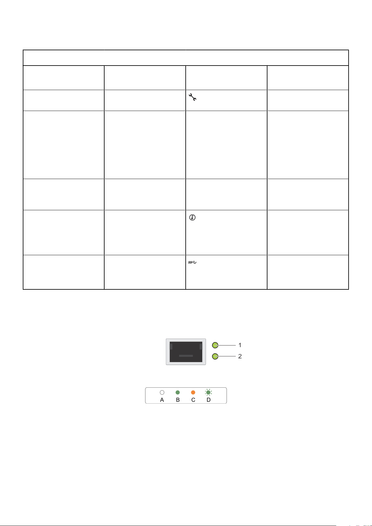
Table 2. Back panel features
Item Indicator, button, or
connector
Icon Description
Technical Specifications on
the product documentation
page.
8 iDRAC Direct micro USB port
9 OCP or OPA card slot N/A
10 EST pull out tab N/A This tab has the unique
11 System id indicator The System Identification(ID)
12 USB 3.0 port (2)
Enables you to connect a
portable device to the sled.
Enables you to connect
Open Compute Project (OCP)
or Omni-Path Architecture
(OPA) expansion cards. For
more information, see the
Dell EMC PowerEdge C6420
Technical Specifications on
the product documentation
page.
Express Service Code,
Service Tag, and MAC
address labels.
LED is available on the back
of the system. Press the
system ID button on the front
of the enclosure to identify a
system in a rack.
The USB ports are 9-pin and
3.0-compliant. These ports
enable you to connect USB
devices to the system.
Network ports indicator codes
Figure 3. LAN indicators on the QSFP OCP card
1. Link indicator
2. Activity indicator
Table 3. QSFP port on OCP card indicator codes
Dell EMC PowerEdge C6420 overview 9
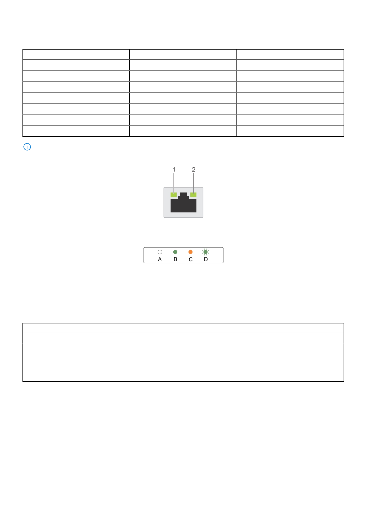
Table 3. QSFP port on OCP card indicator codes
Connection State QSFP Upper green LED QSFP Lower green LED
No link/Not Connected Off Off
InfiniBand Physical Link - No Logical Link Green Off
InfiniBand Logical Link - No Traffic Green Green
InfiniBand Logical Link - Traffic Green Blink
InfiniBand Physical Link Issue Blink Green
Ethernet Link - No Traffic Green Green
Ethernet - Traffic Green Blink
NOTE: The LED blink speed varies according to the traffic bandwidth.
Figure 4. Ethernet port indicator codes
1. Speed indicator
2. Link and activity indicator
Table 4. Ethernet port indicator codes
Convention Status Condition
A Link and activity indicators are off The NIC is not connected to the network.
B Link indicator is green The NIC is connected to a valid network at its maximum port speed.
C Link indicator is amber The NIC is connected to a valid network at less than its maximum port
speed.
D Activity indicator is flashing green Network data is being sent or received.
10 Dell EMC PowerEdge C6420 overview
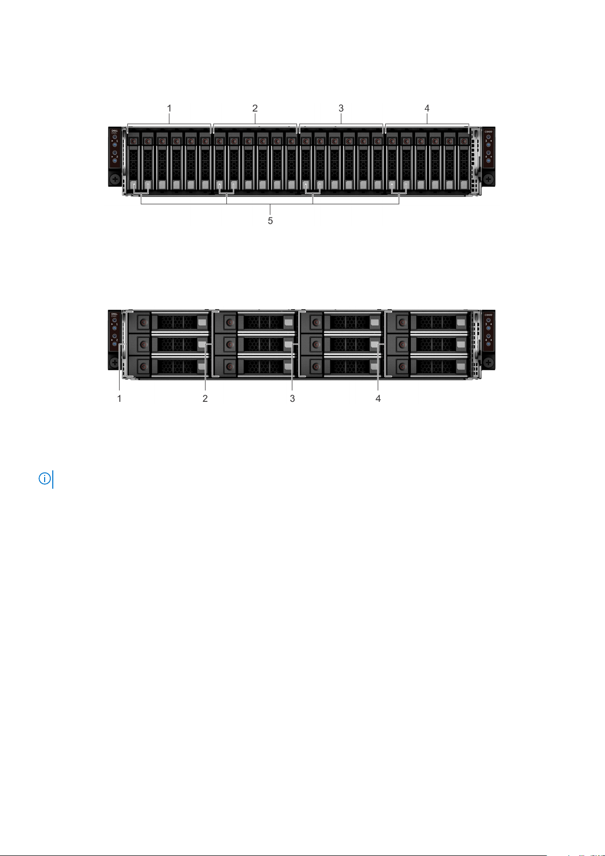
Sled to hard drive mapping
Figure 5. Sled to drive mapping for 24 x 2.5-inch drive configuration
1. Drives 0–5 mapped to sled 1 2. Drives 6–11 mapped to sled 2
3. Drives 12–17 mapped to sled 3 4. Drives 18–23 mapped to sled 4
5. (Optional) NVMe hard drive location
Figure 6. Sled to drive mapping for 12 x 3.5-inch drive configuration
Drives 0–2 mapped to sled 1 2. Drives 3–5 mapped to sled 2
1.
3. Drives 6–8 mapped to sled 3 4. Drives 9–11 mapped to sled 4
NOTE: The warranty of the drives are linked to the Service Tag of the corresponding sled.
Expander zoning
A SAS expander board allows higher, single-volume hard drive configurations. An integrated expander device expands each sleds
hard drive footprint.
The Dell EMC PowerEdge C6400 enclosure supports four sled access to a single expander controller at the same time. The
enclosure provides two expander zoning options:
● Up to 6 SAS/SATA device of each sled in Split Mode (6+6+6+6)
Dell EMC PowerEdge C6420 overview
11
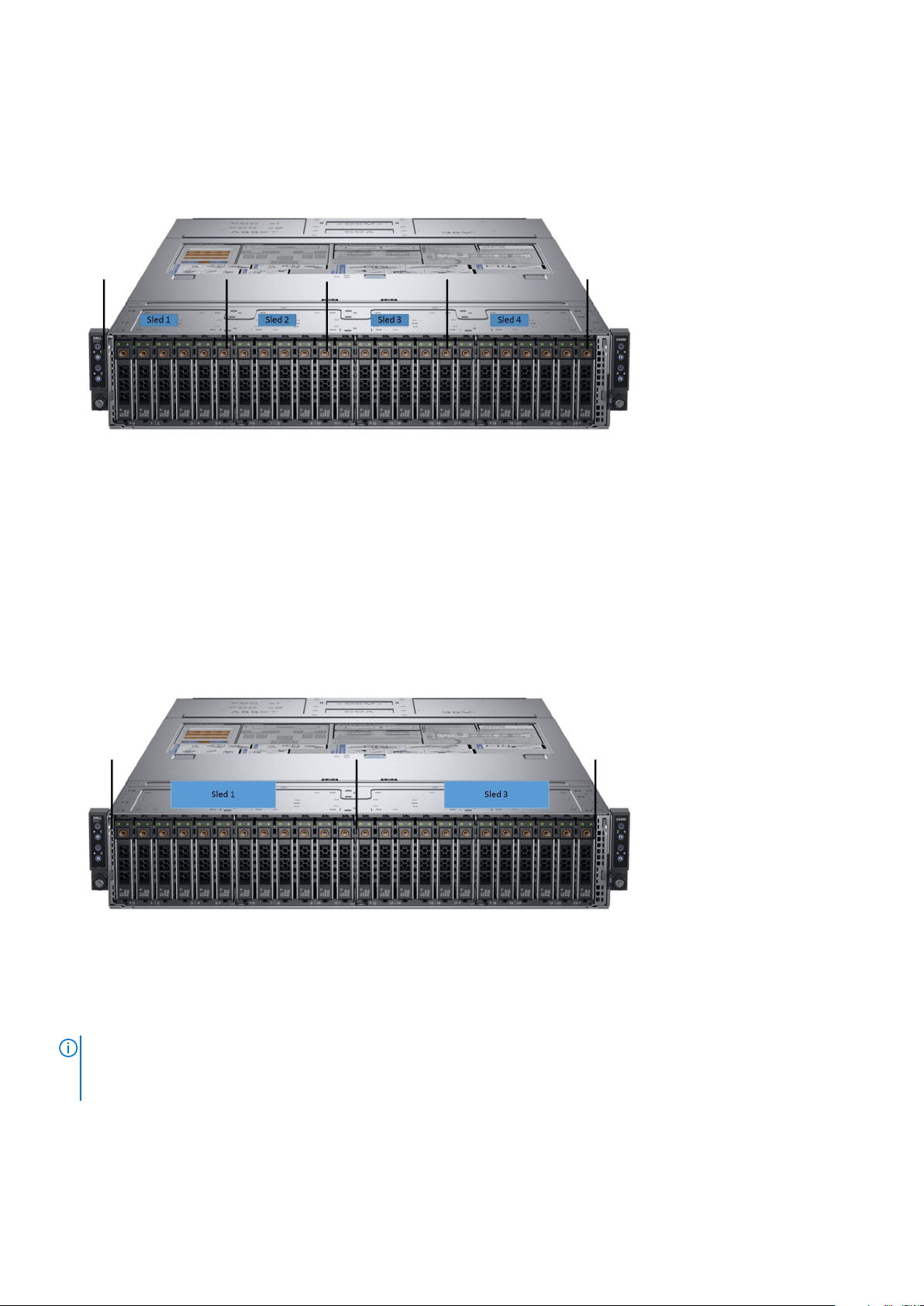
● Up to 12 SAS/SATA device of sled 1 and sled 3 in Zoning Mode (12+12)
NOTE:
● Install expander firmware 2.07 or later to support these configurations
● The expander mode works only with a PERC card, and is not supported by the onboard SATA controller.
12 Dell EMC PowerEdge C6420 overview
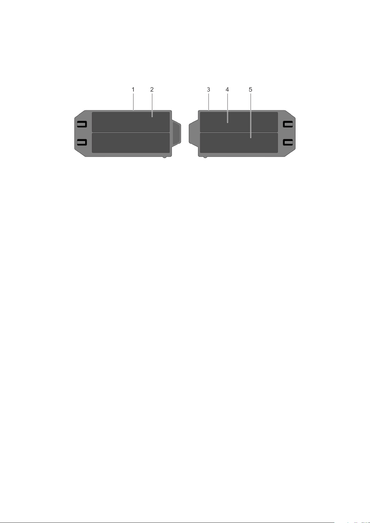
Locating the Service Tag of your system
Your system is identified by a unique Express Service Code and Service Tag number. The Express Service Code and Service
Tag are found on the back of the sled by pulling out the EST tag. This information is used by Dell to route support calls to the
appropriate personnel.
Figure 7. Locating the Service Tag of your system
1. information tag (top view) 2. Express Service Tag label
3. information tag (bottom view) 4. network MAC address information label
5. iDRAC MAC address information label
Dell EMC PowerEdge C6420 overview 13
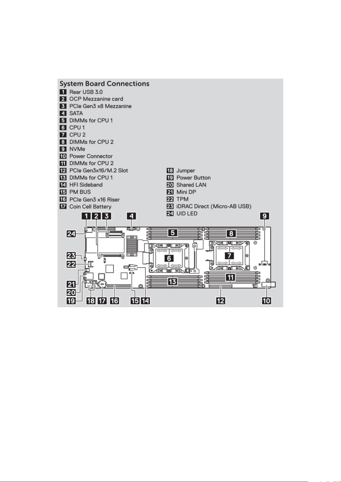
System information label
System board information
Figure 8. System board connections
14
Dell EMC PowerEdge C6420 overview
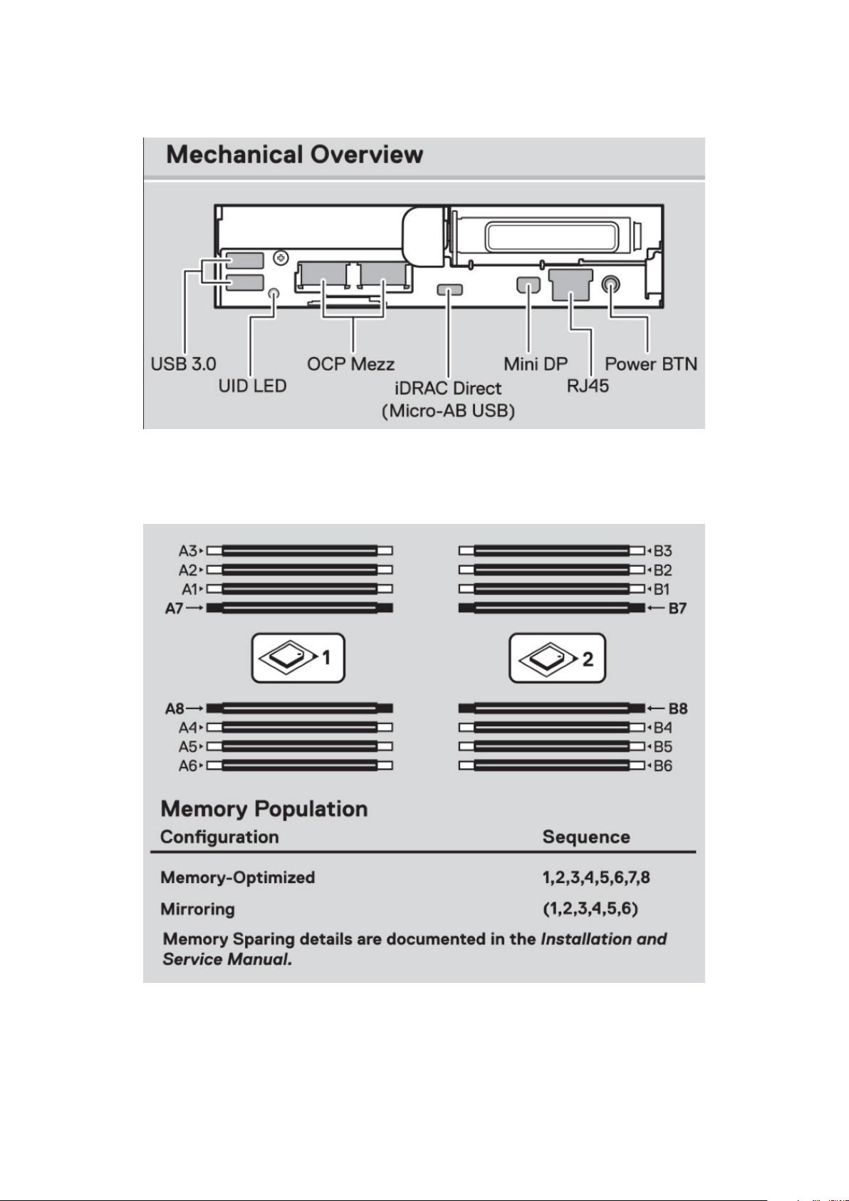
Mechanical overview
Figure 9. Mechanical overview
Memory information
Figure 10. Memory information
Dell EMC PowerEdge C6420 overview
15
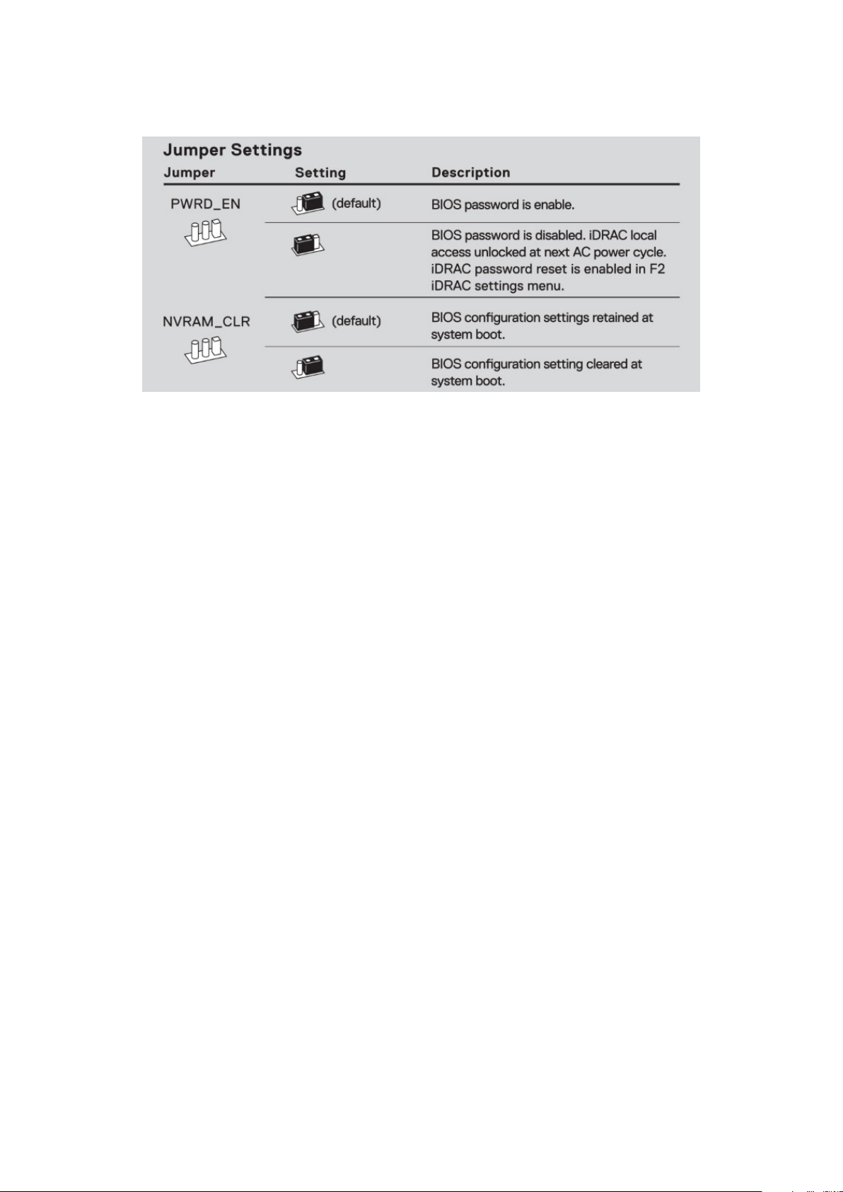
Jumper settings
Figure 11. Jumper settings
16 Dell EMC PowerEdge C6420 overview

2
Initial system setup and configuration
Topics:
• Setting up your system
iDRAC configuration
•
• Options to install the operating system
Setting up your system
Perform the following steps to set up your system:
Steps
1. Unpack the system.
2. Install the system into the rack. For more information about installing the system into the rack, see the Rail Installation Guide
at www.dell.com/poweredgemanuals.
3. Connect the peripherals to the system.
4. Connect the system to its electrical outlet.
5. Power on the system by pressing the power button or by using iDRAC.
6. Power on the attached peripherals.
For more information about setting up your system, see the Getting Started Guide that shipped with your system.
iDRAC configuration
The Integrated Dell Remote Access Controller (iDRAC) is designed to make system administrators more productive and improve
the overall availability of Dell systems. iDRAC alerts administrators about system issues and enables them to perform remote
system management. This reduces the need for physical access to the system.
Options to set up iDRAC IP address
To enable communication between your system and iDRAC, you must first configure the network settings based on your
network infrastructure.
NOTE: For static IP configuration, you must request for it at the time of purchase.
This option is set to DHCP by Default. You can set up the IP address by using one of the following interfaces:
Interfaces
iDRAC Settings
utility
Dell Deployment
Toolkit
Dell Lifecycle
Controller
iDRAC Direct and
Quick Sync 2
(optional)
Document/Section
Dell Integrated Dell Remote Access Controller User's Guide at www.dell.com/poweredgemanuals
Dell Deployment Toolkit User’s Guide at www.dell.com/openmanagemanuals > OpenManage Deployment
Toolkit
Dell Lifecycle Controller User’s Guide at www.dell.com/poweredgemanuals
See Dell Integrated Dell Remote Access Controller User's Guide at www.dell.com/poweredgemanuals
Initial system setup and configuration 17

NOTE: To access iDRAC, ensure that you connect the ethernet cable to the iDRAC9 dedicated network port. You can also
access iDRAC through the shared LOM mode, if you have opted for a system that has the shared LOM mode enabled.
Log in to iDRAC
You can log in to iDRAC as:
● iDRAC user
● Microsoft Active Directory user
● Lightweight Directory Access Protocol (LDAP) user
The default user name and password are root and calvin.
NOTE: You must have the iDRAC credentials to log in to iDRAC.
NOTE: Ensure that you change the default username and password after setting up the iDRAC IP address.
For more information about logging in to the iDRAC and iDRAC licenses, see the latest Integrated Dell Remote Access Controller
User's Guide at www.dell.com/poweredgemanuals.
You can also access iDRAC by using RACADM. For more information, see the RACADM Command Line Interface Reference
Guide at www.dell.com/poweredgemanuals.
Options to install the operating system
If the system is shipped without an operating system, install a supported operating system by using one of the following
resources:
Table 5. Resources to install the operating system
Resources Location
iDRAC www.dell.com/idracmanuals
Lifecycle Controller www.dell.com/idracmanuals > Lifecycle Controller
OpenManage Deployment Toolkit www.dell.com/openmanagemanuals > OpenManage
Deployment Toolkit
Dell certified VMware ESXi www.dell.com/virtualizationsolutions
Installation and How-to videos for supported operating
systems on PowerEdge systems
Supported Operating Systems for Dell EMC PowerEdge
systems
Methods to download firmware and drivers
You can download the firmware and drivers by using any of the following methods:
Table 6. Firmware and drivers
Methods Location
From the Dell EMC support site www.dell.com/support/home
Using Dell Remote Access Controller Lifecycle Controller
(iDRAC with LC)
Using Dell Repository Manager (DRM) www.dell.com/openmanagemanuals > Repository Manager
Using Dell OpenManage Essentials www.dell.com/openmanagemanuals > OpenManage Essentials
Using Dell OpenManage Enterprise www.dell.com/openmanagemanuals > OpenManage
Using Dell Server Update Utility (SUU) www.dell.com/openmanagemanuals > Server Update Utility
18 Initial system setup and configuration
www.dell.com/idracmanuals
Enterprise

Table 6. Firmware and drivers
Methods Location
Using Dell OpenManage Deployment Toolkit (DTK) www.dell.com/openmanagemanuals > OpenManage
Deployment Toolkit
Using iDRAC virtual media www.dell.com/idracmanuals
Downloading drivers and firmware
Dell EMC recommends that you download and install the latest BIOS, drivers, and systems management firmware on your
system.
Prerequisites
Ensure that you clear the web browser cache before downloading the drivers and firmware.
Steps
1. Go to www.dell.com/support/home.
2. In the Drivers & Downloads section, type the Service Tag of your system in the Enter a Service Tag or product ID box,
and then click Submit.
NOTE: If you do not have the Service Tag, select Detect Product to allow the system to automatically detect the
Service Tag, or click View products, and navigate to your product.
3. Click Drivers & Downloads.
The drivers that are applicable to your system are displayed.
4. Download the drivers to a USB drive, CD, or DVD.
Initial system setup and configuration
19

Installing and removing enclosure
Topics:
• Safety instructions
• Before working inside your system
• After working inside your system
• Recommended tools
• Dell EMC PowerEdge C6420 sled
• PERC battery
• Air shroud
• System memory
• Support bracket
• Linking board and PCIe cable
• Processor and heat sink module
• Expansion cards
• M.2 SSD module
• Mezzanine and OCP cards
• System battery
• System board
• Trusted Platform Module
3
components
Safety instructions
NOTE:
Whenever you need to lift the system, get others to assist you. To avoid injury, do not attempt to lift the system by
yourself.
WARNING: Opening or removing the system cover while the system is powered on may expose you to a risk of
electric shock.
CAUTION: Do not operate the system without the cover for a duration exceeding five minutes. Operating the
system without the system cover can result in component damage.
CAUTION: Many repairs may only be done by a certified service technician. You should only perform
troubleshooting and simple repairs as authorized in your product documentation, or as directed by the online or
telephone service and support team. Damage due to servicing that is not authorized by Dell is not covered by
your warranty. Read and follow the safety instructions that are shipped with your product.
NOTE: It is recommended that you always use an antistatic mat and antistatic strap while working on components inside
the system.
CAUTION: To ensure proper operation and cooling, all bays in the system and system fans must be always
populated with a component or a blank.
Before working inside your system
Prerequisites
Follow the safety guidelines listed in Safety instructions.
20 Installing and removing enclosure components

Steps
1. Power off the system, including all attached peripherals.
2. Disconnect the system from the electrical outlet and disconnect the peripherals.
After working inside your system
Prerequisites
Follow the safety guidelines listed in Safety instructions.
Steps
1. Install the sled into the enclosure.
2. Reconnect the peripherals and connect the system to the electrical outlet.
3. Power on the attached peripherals and then power on the system.
Recommended tools
You need the following tools to perform the removal and installation procedures:
● Phillips #1 screwdriver
● Phillips #2 screwdriver
● 1/4 inch flat head screwdriver
● Wrist grounding strap
● ESD mat
Dell EMC PowerEdge C6420 sled
Sled Installation Guidelines
NOTE: Ensure to install a sled blank in all the empty slots. Operating the enclosure without a blank results in overheating.
NOTE: For optimized thermal operation, ensure to follow the sled population sequence mentioned below:
Installing and removing enclosure components 21
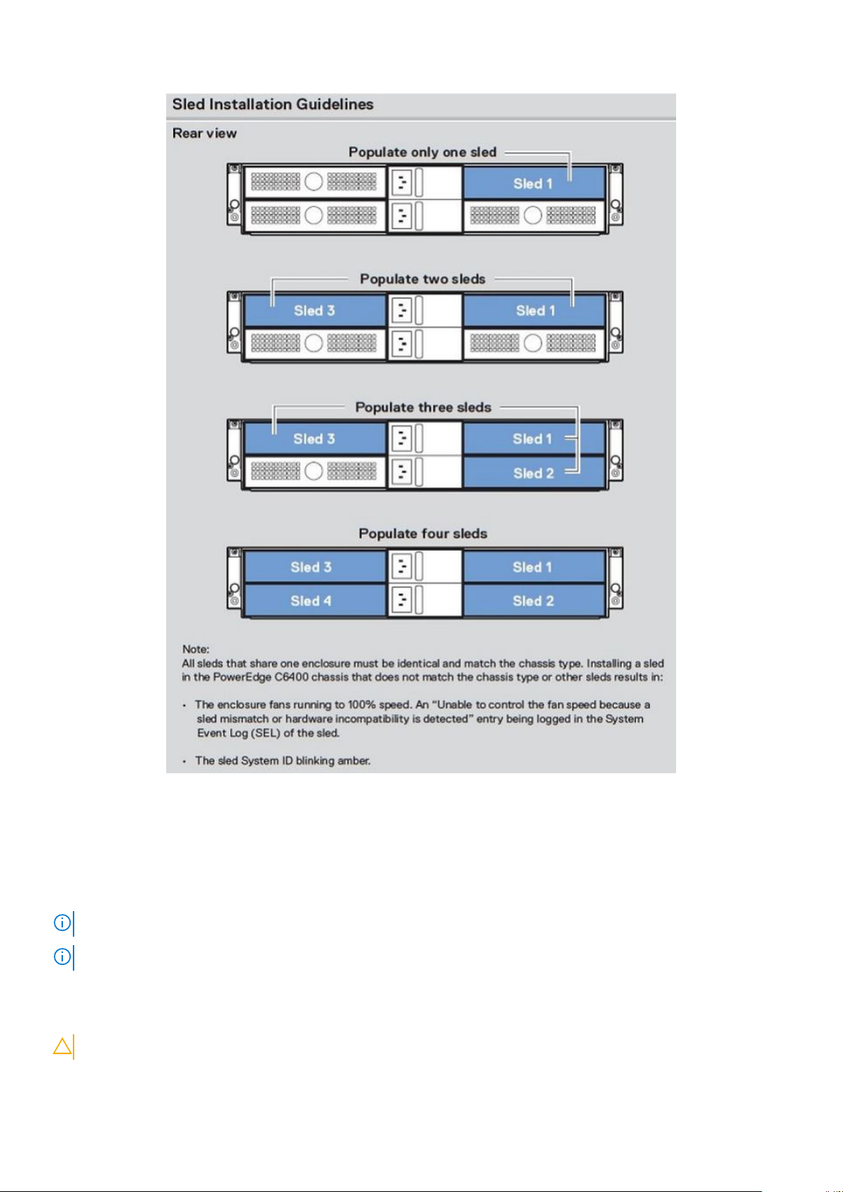
Figure 12. Sled Installation Guidelines
Removing a sled
Prerequisites
1. Follow the safety guidelines listed in Safety Instructions.
NOTE: For optimized thermal performance, see Sled installation guidelines.
NOTE: The procedure to remove a sled blank or a sled are the same.
Steps
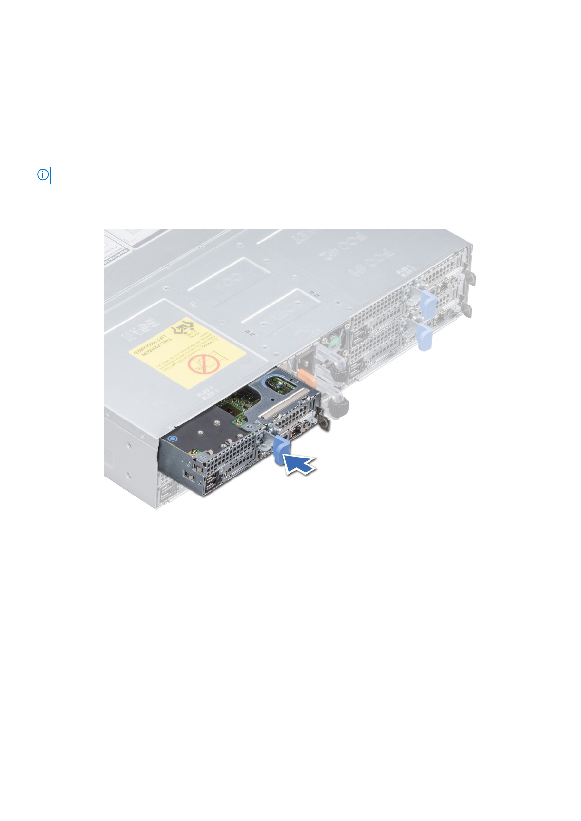
Press the retaining latch and using the sled pull handle, slide the sled out of the enclosure horizontally.
CAUTION: Ensure that the sled is supported with both hands while it is being slid out.
22 Installing and removing enclosure components
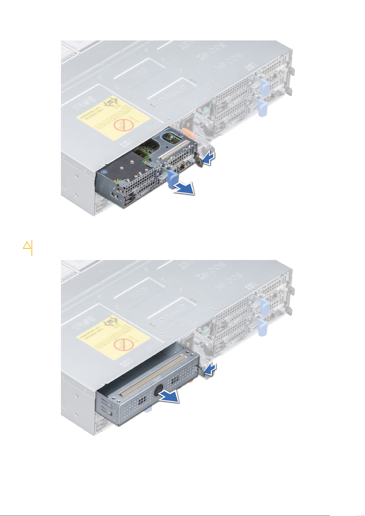
Figure 13. Removing a sled
CAUTION:
without a blank, for an extended time can result in overheating.
If you are permanently removing the sled, install a sled blank promptly. Operating the enclosure
Figure 14. Removing a sled blank
Installing and removing enclosure components
23
Next steps
1. Install the sled or Install a sled blank.
Installing a sled
Prerequisites
1. Follow the safety guidelines listed in Safety Instructions.
NOTE: For optimized thermal performance, see Sled installation guidelines.
Steps
1. Align the sled to the enclosure horizontally to insert the sled into the enclosure.
Figure 15. Installing a sled
24
Installing and removing enclosure components
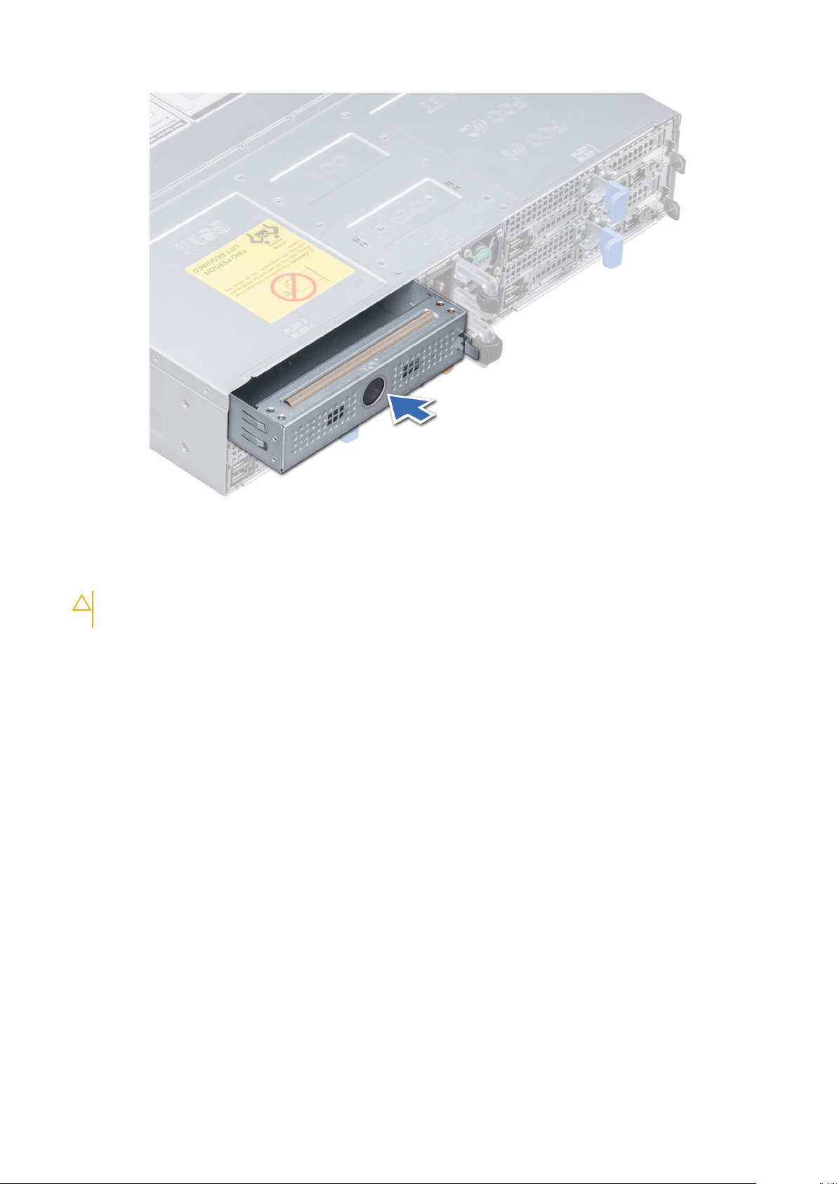
Figure 16. Installing a sled blank
2. Push the blue retention latch to slide the sled into the enclosure, and stop the sled at a distance of 20-30 mm before
complete insertion of the sled as shown in the image below.
CAUTION:
two-position insertion and gently slide the sled into the enclosure.
To avoid any damages to the pins on the sled, do not force the sled into the enclosure. Follow the
Installing and removing enclosure components 25
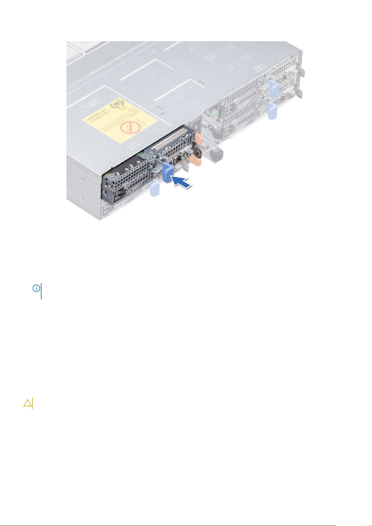
Figure 17. Stop the sled at a distance of 20-30 mm before complete insertion
3. Slide the blue retention latch gently, until the sled locks into the place.
Next steps
1. Follow the procedure listed in After working inside your enclosure.
NOTE:
To add the Service Tag of the system board to match the Service Tag of the physical node, contact Dell
Technical Support.
PERC battery
Removing the PERC battery
Prerequisites
1. Follow the safety guidelines listed in Safety instructions.
2. Follow the procedure listed in Before working inside your system.
3. Remove the sled from the enclosure.
4. If applicable, disconnect the battery cable from the PERC card.
CAUTION: Do not hold the battery cable and lift the battery out.
Steps
Holding the cable end of the battery, lift the battery out of the air shroud.
26
Installing and removing enclosure components
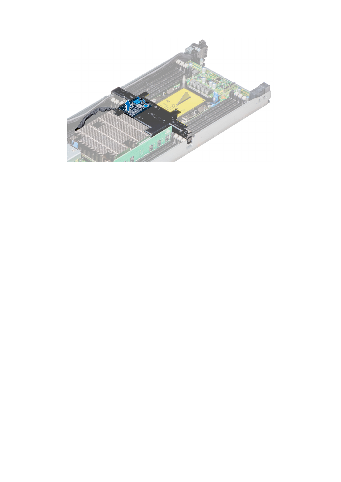
Figure 18. Removing the PERC battery
Next steps
1. Install the PERC battery.
Installing the PERC battery
Prerequisites
1. Follow the safety guidelines listed in Safety instructions.
2. Follow the procedure listed in After working inside your system.
3. Install the sled from the enclosure.
4. If applicable, connect the battery cable from the PERC card.
Steps
1. Align and insert the non cable end of the PERC battery into the battery slot on the air shroud.
2. Press the battery until it locks into place.
Installing and removing enclosure components
27
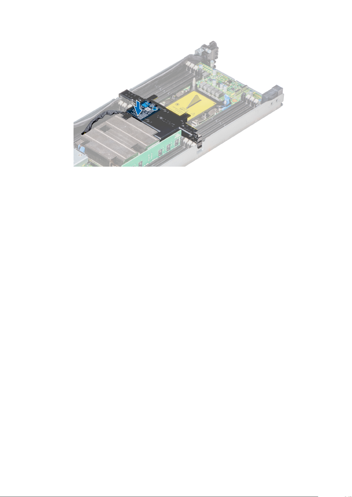
Figure 19. Installing the PERC battery
Next steps
1. If disconnected, connect the battery cable to the PERC card.
2. Follow the procedure listed in After working inside your system.
Air shroud
Removing the air shroud
Prerequisites
1. Follow the safety guidelines listed in Safety instructions.
2. Follow the procedure listed in Before working inside your system.
3. If applicable, disconnect the battery cable from the PERC card.
Steps
1. Press the clip on the air shroud to release the shroud from the sled.
2. Remove the shroud by rotating the shroud and releasing the hinge from the slot on the system.
28
Installing and removing enclosure components
 Loading...