


T5, T14D, T20C, T24C, T40
Blast Chiller/Shock Freezers
Service, Installation and Care Manual
Please read this manual completely before attempting to install or operate this equipment! Notify carrier of damage! Inspect all components immediately. See page 2.
Blast Chillers/Shock Freezers
IMPORTANT |
INFORMATION |
|||||
|
|
USE |
||||
|
READ |
BEFORE |
|
|||
|
|
|
INSTRUCTIONS! |
|||
|
SAVE |
THESE |
||||
PLEASE |
|
|
||||
|
|
|
|
|
||
|
|
|
|
|
|
|
June 2010
CONTENTS
1.GENERAL DOCUMENTATION
1.1 |
General information |
page |
4 |
1.2 |
Installation |
page |
4 |
1.3 |
Transport and handling |
page |
4 |
1.4 |
Unpacking - disposal of packaging materials |
page |
4 |
1.5 |
General safety regulations |
page |
4 |
2.INSTALLATION
2.1 |
Data plate information |
page |
5 |
2.2 |
Positioning |
page |
5 |
2.3 |
Ambient temperature and air circulation |
page |
5 |
2.4 |
Electrical connections |
page |
5 |
2.6 |
Condensate drainage connection |
page |
6 |
2.7 |
Information for the installation technician |
page |
6 |
2.8 |
Safety and control systems |
page |
6 |
2.9 |
Appliance disposal |
page |
6 |
2.10 Door Hinge Reversal Procedure |
page |
7-10 |
|
3.ADVICE TO ENSURE EFFICIENT APPLIANCE OPERATION
3.1 |
Shut-down procedures |
page |
11 |
3.2 |
Operating tips |
page |
11 |
3.2.1 |
Precooling |
page |
11 |
3.2.2 |
Loading the appliance |
page |
11 |
4. |
DESCRIPTION OF THE CONTROL PANEL |
page |
12 |
4.1 |
Push-buttons |
page |
13 |
5.PROGRAMMING AND OPERATING INSTRUCTIONS
5.1 |
Starting up the appliance |
page |
14 |
5.2 |
Soft blast chilling by temperature |
page |
15 |
5.3 |
Soft timed blast chilling |
page |
16 |
|
Hard blast chilling |
page |
16 |
5.4 |
Hard blast chilling by temperature |
page |
17 |
5.5 |
Hard timed blast chilling |
page |
17 |
5.6 |
Blast freezing by temperature |
page |
18 |
5.7 |
Timed blast freezing |
page |
19 |
6.APPLIANCE FUNCTIONS
6.1 |
Date and time settings |
page |
20 |
6.2 |
Ice cream surface hardening |
page |
20 |
6.3 |
Muting the beeper and alarm reset |
page |
20 |
6.4 |
Program storage |
page |
20 |
6.5 |
Displaying the three latest HACCP alarms |
page |
21 |
6.6 |
Printing out stored data |
page |
21 |
6.7 |
Forced ventilation function |
page |
21 |
6.8 |
Manual defrosting |
page |
21 |
6.9 |
Automatic defrost cycles |
page |
21 |
6.10 |
Printer operation |
page |
21 |
7.ALARM MANAGEMENT
7.1 |
Storage of data/errors |
page |
22 |
7.2 |
Alarms list |
page |
22-25 |
8.MAINTENANCE AND CLEANING
8.1 |
General safety regulations |
page |
26 |
8.2 |
Cleaning the condenser |
page |
26 |
8.3 |
Cleaning the internal room |
page |
26 |
8.4 |
Defrost water drainage |
page |
26 |
9. |
Blast chiller and remote condenser specs |
page |
27-35 |
10. |
T5/T14D refrigeration system schematic |
page |
36 |
11. |
Wiring diagrams |
page |
37-41 |
12. |
T40 Assembly instructions |
page |
42-45 |
13. |
Warranties |
page |
46-47 |

1. General Documentation
1.1. General information
•This manual is an integral part of the product, providing all the information required to ensure correct installation, operation and maintenance of the machine.
•Read the manual carefully, making reference
to it for machine operation. Keep the manual in a safe place where it can be accessed by all authorised operators (installers, operators and service personnel).
•The machine has been designed for professional applications only and should only be operated by qualified personnel.
•The machine must only be used for the purposes for which it was designed, i.e. for chilling and
freezing food products.
The machine must not be used for products requiring constant temperature control and recording, such as:
-heat-sensitive chemicals,
-medicines or
-blood products.
•The manufacturer declines all responsibility for any damage caused by incorrect or unreasonable machine use, such as:
•improper use by untrained persons;
•technical modifications or operations not suited to specific models;
•use of non-original or non-specific spare parts;
•failure to follow the instructions given in this manual.
1.2Installation
In the event that the machine is fitted with a remote condenser unit, the installation technician is responsible for checking all
connections in compliance with the instructions given by Delfield for plant and machine installation.
1.3Transport and handling
•To load or unload the machine and/or components from/onto the means of transport, use a lift truck or fork lift equipped with forks that are at least half the length of the machine housing; use a crane if the machine is fitted with eye bolts. Select the lifting equipment suited
to the weight and overall dimensions of the
packaged machine/components.
•When handling the machine/ components, apply all precautions to prevent damage, in compliance with the information given on the packaging material
1.4Unpacking
•Remove all cardboard, wood or other materials from the wood base on which the machine is set. Lift the machine/components with suitable means (e.g. lift truck), remove the wood base, then position the machine/components in the allocated site.
•Once all packing material has been removed,
check that the machine has not been damaged in any way.
•Remove the protective PVC film on the stainless steel panels from all internal and external surfaces (fig. 2).
•Always wear protective
gloves when handling packing material and the wood base.
•NB Dispose of packing materials in compliance with disposal regulations applied in the country where the machine is to be installed. Never dispose of materials in the environment.
1.5General safety regulations
Failure to observe the recommendations made by the present manual will be at the entire responsibility of the machine user. The main safety regulations are as follows:
-do not touch the machine with moist or wet hands or feet;
-never operate the machine while barefoot;
-do not insert screwdrivers, cooking utensils or any other object between the guards and moving parts;
-before performing cleaning or routine maintenance operations, disconnect the machine from the power supply at the master switch and the main knife switch (if present);
-never pull on the power cable to disconnect the machine from the power supply.

2. Installation
2.1Data plate information
•Check that the data specified on the plate correspond to the characteristics of the power supply (V, kW, Hz, no. phases and power available).
•The dataplate with appliance specifications
is located at the rear exterior of the machine and/or on the electrical boards (fig. 3). The setup of individual units and the installation of condensers are subject to the fire-safety regulations
of the country in which the machine is installed; seek all necessary advice from the local firefighting authorities. Bear in mind that the intervention of safety valves or plug fuses in the refrigerating circuit will lead to the immediate discharge of refrigerant into the environment.
2.2Positioning
•The machine must be installed in complete compliance with safety regulations, procedures and standing laws.
•Position the machine in the allocated site.
•Adjust the machine feet by turning the foot clockwise until the appliance is perfectly level. In the case of particularly heavy equipment, use appropriate lifting means.
(fig. 4).
• If the appliance is not perfectly level, correct operation and condensate flow-off will not be assured.
AVOID
•direct exposure to sunlight;
•closed sites with high temperatures and poor air circulation;
•installing the machine near sources of heat
Installation Clearance Requirements
All Cabinets:
12” clearance above top
12” clearance on sides and rear
Remote condensing units for T20, T24 and T40 models.
24” clearance above top
6” clearance on sides and rear
2.3 Ambient temperature and air circulation
For air-cooled appliances, the maximum ambient temperature for operation is 90°F / 32°C. Correct operation cannot be guaranteed at higher temperatures. The machine may operate safely to a maximum temperature of 100°F / 38°C.
Remote condensing units may be installed indoors next to the unit or within 25 ft. Consult Delfield if placementwill be greater than 25
ft. away. Remote condensing units may also be installed outdoors but require a U.L. listed enclosure which is supplied as an option from Delfield. Sufficient air circulation must be guaranteed at all times.
2.4 Electrical connections
A dedicated thermal-magnetic circuit breaker compliant with established regulations must be installed on the appliance power line.
•Connected electrical cables must correspond to the technical data (as specified on electrical drawings provided by the installation technician).
Connect the earthing conductor to an efficient earthing system.
THE MANUFACTURER DECLINES ALL LIABILITY AND GUARANTEE OBLIGATIONS IN THE EVENT OF INJURY TO PERSONS OR DAMAGE TO EQUIPMENT AND OBJECTS DUE TO INCORRECT INSTALLATION AND/OR FAILURE TO COMPLY WITH STANDING INSTALLATION REGULATIONS.
2.6 Condensate drainage connection
For models T20C-T24C-T40 fit a condensate water drainage hose with a minimum diameter of 1” . Provide a waste pipe with a trap with a diameter of at least 1 1/2” at floor level.
2.7 Information for the installation technician (T20C, T24C and T40)
Before starting up the machine, check that it has been correctly installed.
1.Check that there are no gas leaks from weldings or joints made during installation works.
2.Check that the pipes connecting the condenser to the remote condensing unit have been well insulated.
3.Check all wiring connections.
4.Check electrical input.
5.Check the standard pressure in the refrigerant system.
6.Perform at least one blast freezing cycle (to the SET temperature) and one manual defrosting cycle. In the event that the appliance or
the remote condensing unit have not been transported in a vertical position (e.g. on the back) or have been overturned during
installation works, allow at least 4 hours before starting up the equipment.
2.8Safety and control systems
•Door microswitch: shuts down fan operation in the cell when the door is opened.
•General fuses: protect the power circuit against short circuiting and overloads.
•Compressor heat relay: intervenes in the event of overloads or operating faults.
•Safety pressure switch: intervenes in the event of excessive pressure in the refrigerant circuit.
•Plug fuses: intervene in the event of verpressure or operating fault in the safety pressure switch (see above).
•Chamber temperature control: operated by the electronic board by means of a probe inside the cell.
•Temperature control end defrost cycle: controlled by the electronic board by means of the probe in the evaporator.
2.9Appliance disposal
After the useful life of the applicance has been realized, be sure to demolish and dispose of the machine in compliance with the regulations applied in the country of installation, particularly in regards to refrigerant gas and compressor lubricant oil.

T5/T14D DELFIELD2.10PROCEDURADoor HingePER LAReversalOTAZIONE DELLAProcedurePORTA
DOOR ROTATION PROCEDURE
1.RimuovereRemove 4laboltspresafromdʼariathefrontaleair intakesvitandopanelle 4bottomviti delledgecerniere. lato inferiore Remove the air front intake panel unscrewing the 4 screws of inferior hinge
2.AprireOpen lathepresaair intdʼariake fropanelta emakif cendog alevaleverconwithun cacsciaviterewdriversu ntrambion bothi latisides. Open the air intake panel making a lever with a screwdriver on both sides
3.ScollegareDisconnectil connettorethe printerdallacablesscheda. pulsanti Remove the connector from the push buttons card
4. Remove the two lower hinge bolts.
4.Svitare le 2 viti che fissano la cerniera inferiore Unscrew the 2 bolts that fix the inferior hinge

5. Remove5.Rimuoverethe chillerla pdortaor. dellʼabbattitore Remove the chiller door
6.6Remove.Ri uoverethelarightcernieratop hingesup riore. Rotatedestrait 180ºruotarlaanddiinstall180° edit on the left top side of the chiller. installarla sul lato sinistro dellʼabbattitore Remove the right top hinge and rotate it of 180° and provide to install it on the left top side of chiller

Lower right hinge |
Lower left hinge |
Cerniera inferiore destra |
Cerniera inferiore sinistra(in |
|
(left hinge supplied |
Lower right hinge |
dotazione) |
asLowaccessory)left hinge |
|
|
(left hinge as accessory) |
7.Move the black washer and the plastic bushing from the right hinge to the left hinge.
7.Spostare la guarnizione nera e la boccola in plastica dalla cerniera destra su quella sinistra Move the black gasket and the plastic buckle from the right hinge to the left hinge.
8.RuRotaterethela portadoordi180º180°aned insertstallarethelalowercernieraleftinferiorehinge.
Sinistra. Rotate the door of 180° and install the inferior left hinge .
9.Installaretheladpoor,rta fisinsertingando lathecernieratop hinginferintoore sinistrathe prepunchednegli appositiholes,forialigningpred spostithe left lower Installhingethewithdoorthefixingprepunchedthe left inferiorholes. hinge in the predisposed holes

10.FissareAdjust thela portadoor effettuandodoor hingesla regtolazioneguaranteedellea correctcerniereclosingmodoanddasealinggarantireof theunagasketcorretta. Install the two
chiusuraloweredhingeaderenzabolts. della guarnizione porta. Successivamente bloccare definitivamente le 2 cerniere.
11Reinstallare. Use puttyla targhettaknife or similaradesivatoolsultofrontalepeel offdellathe adhesiveporta reinstallarenameplatela. Rotate,presa dʼariaand readhereseguendothelenameplate.
istruzioni.
12. Reconnect the printer cables.
Attenzione:
13. Reinstall the front air intake panel.
il micro della porta funz ona se allineato al magnete schiumato allʼinterno della stessa.
In caso di allarme porta aperta regolare la posizione della porta e/o micro.(vedi ultime foto)
Attention: The door micro switch works if it’s aligned to the magnet positioned inside the door. In case the door alarms, adjust the door and/or the micro switch position. See pictures below.
regulation so that |
of |
the 2 screws door
.
itʼs aligned |
door. |
provide to |
|
IL MICRO Eʼ POSIZIONATOMicro switchSULpositionedLATO frontFRONTALEside nearVICINOthe condenserAL CONDENSATORE 10 MICRO SWITCH POSITIONED FRONT SIDE NEAR THE CONDENSER
3. ADVICE TO ENSURE EFFICIENT APPLIANCE OPERATION
3.1 Shut-down procedures
In the event of emergency, shut down the appliance by switching off power at the main panel, by means of a breaker or power disconnect or by removing the plug from the power socket.
3.2 Operating tips
Before starting up the appliance, clean the inside of the compartment thoroughly.
3.2.1 Pre-cooling
Before using the appliance for the first time, or after a prolonged period of disuse, precool the compartment by running an empty cycle until the set operating temperature has been reached.
To ensure optimal performance without any alteration to food quality: arrange food products in such a way as to favour the circulation of cold air throughout the compartment; open the door as little as possible.
3.2.2 Loading the appliance
a)Ensure that foods to be chilled and/or frozen are separate and do not have a thickness greater than 2’’/50mm-3’’/80mm. Do not load the appliance beyond the quantity recommended by the manufacturer.
b)Ensure that there is sufficient clearance between trays to enable free air circulation. If the appliance is not completely full, distribute the trays and foods evenly throughout the available space.
c) Position trays inside the tray compartment as far as they will go, as close as possible to the evaporator.
d)Position the core probe at the centre of the largest product or food item; make sure that the tip of the probe does not protrude or touch the tray. The probe must be cleaned and sanitised before each new cycle (operation) to prevent inadvertent contamination.
e)Avoid covering the trays and/or containers with insulating covers or film. The more the product is insulated, the more time is required for chilling or freezing. Trays should be packaged when the product has been chilled, before being placed in storage.
11

4. DESCRIPTION OF THE VERTICAL CONTROL PANEL
2
5a
5
6
15
1
12
10
|
|
|
3 |
|
HARD |
|
|
+38ο |
+38ο |
0ο |
4 |
|
|
|
5b |
 οC
οC
14
7
8
13
9
11
HACCP PROGRAM
12
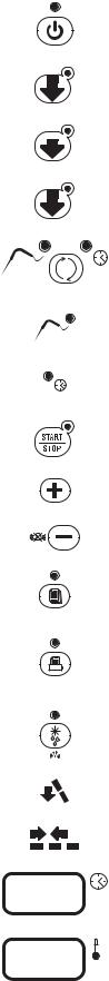
4.1PUSH-BUTTONS :
1.
2.
3.
4.
5.
5A.
5B.
6.
7.
8.
9.
10.
11.
12.
13.
14.
15.
|
ON /OFF (STAND BY) |
|
+38ο |
SOFT BLAST CHILLING CYCLE (+38°F / +3°C) |
|
|
||
HARD |
HARD BLAST CHILLING CYCLE (+38°F / +3°C) |
|
+38ο |
||
|
||
0ο |
BLAST FREEZING CYCLE (0°F / -18°C) |
|
|
END CYCLE BY TIME / PROBE (TEMPERATURE)
PROBE CHILLING INDICATOR LED
TIMED CHILLING INDICATOR LED
CYCLE START / STOP
INCREASE VALUE
DECREASE VALUE
PROGRAM RECIPE PROGRAMS (CHILLING CYCLES)
HACCP HACCP AND PRINTER (OPTIONAL)
DEFROSTING / FORCED VENTILATION
CHILLING / FREEZING CYCLE INDICATOR LED
STORAGE INDICATOR LED
TIME DISPLAY
 οC
οC
TEMPERATURE DISPLAY
13

5. Programming and operating instructions
5.1 STARTING UP THE APPLIANCE (only for T14D / T20C / T24C / T40)
PRE HEATING FUNCTION OF COMPRESSOR SUP |
30” |
|
When power is initially supplied to the cabinet, a 2-hour pre-heating phase starts and the display shows some blinking dashes “---”. During this phase the machine cannot be started. This important information is shown on a yellow label placed inside the door.
Initial pre-heating is necessary in order to safeguard the compressor’s life. Only if strictly necessary (and under the customer’s responsibility) it is possible to by-pass countdown by pressing push button “Printer/ HACCP” for about 5 seconds.
This function is not activated if machine stops/starts operating due to lack of power during working cycle.
When the appliance is powered up, it can be:
• ON displays 15 |
and 16 |
off |
|
οC and left LED 5A |
on push-button 5 |
on, LED 1 |
• OFF-STAND-BY LED on push-button 1  on
on
To switch from one status to another, press push-button 1  .
.
Whenever the appliance switches from STAND-BY status to ON, a self-test is carried out: all LEDs and displays are switched on, push-buttons are checked, then the installed software version is displayed.
OPERATION
The main work cycles (chilling/freezing) performed by the appliance:
• SOFT BLAST CHILLING (+38°F / +3°C)
Pre-cooked food is rapidly chilled (90’) to a temperature of +38°F / +3°C, thus preventing proliferation of bacteria and preventing dehydration of the cooked food due to evaporation. Food can
thus be stored perfectly for 5 to 7 days without altering its original qualities. The soft cycle is recommended for delicate, thin foods such as rice, vegetables and fried foods.
• HARD BLAST CHILLING (+38°F / +3°C)
This process is designed to cool food products with a thickness greater than 2-3 cm/1’’ and is very effective for dense, greasy or large-sized foods. Variable air temperatures are used to accelerate penetration of cold into the product.
• BLAST FREEZING (0°F / -18°C)
This function freezes the product completely to a temperature of 0°F / -18°C in approximately 4 hours. The rapidity of the process prevents formation of macrocrystals essential to ensure that the product retains its original consistency and quality when thawed for consumption.
• AUTOMATIC CONSERVATION
At the end of each cycle (chilling or freezing), the appliance will automatically switch to the required storage temperature.
Two different end-cycle modes are available for each cycle:
•BY TEMPERATURE - the cycle ends when the probe reaches the required temperature.
•TIMED - cycle length is pre-set

IMPORTANT: work cycles and modes can only be selected when the appliance is ON (LED on push - button 6  off)
off)
IMPORTANT: The appliance will automatically defrost if coil temperature falls below 45˚F. It will not go into defrost during a chill or freeze cycle. When it is in defrost a new cycle can not be initiated until defrost is complete.
5.2 SOFT BLAST CHILLING BY TEMPERATURE (pre-cooked, hot foods)
•To select this cycle, press push-button 2 +38ο (relative LED lights up), then press push-button 5 


 to select the temperature mode (LED 5A
  on)
on)
•Insert the core probe into the core of the product to be chilled.
•Start up the cycle by pressing push-button 6  . LED 5A
  and those related to the push-buttons
pressed illuminate throughout the cycle, while LEDs 12  flash.
•Display 15 
 indicates the maximum blast chilling time (starting temperature to end of the blast chilling temperature (factory setting 90 minutes).
•The temperature measured by the core probe is shown by display 16 
 οC .
οC .
•The instrument timer starts the countdown of the maximum blast chilling time as soon as the temperature measured by the core probe falls below the temperature of +149°F / +65°C (the dot at
the bottom right of display 15 
 flashes).
•During the blast chilling cycle, the air temperature is around +32°F / 0°C and may get as low as 23˚F/-5˚C. This function is designed to guarantee uniform cooling of the product, preventing frost formation
on the surfaces. During the blast chilling cycle, the compressor may therefore stop and restart, depending on the reading of the compartment temperature probe.
•The blast chilling phase ends only when the core probe (inserted in the product core) indicates
that the set blast chilling temperature (+38°F / +3°C) has been reached as signalled by an intermittent beep for a minute. During the beep, LEDs 13  and 14
 flash.
Display 16 
 οC indicates the temperature inside the compartment, while display 15
 shows blast chilling time reset to zero.
• If at the end of the maximum blast chilling interval the core probe continues to display a temperature higher than the value for the end of blast chilling, the displays will indicate an alarm for
excessively long chilling (ALL 14) alternating with the temperature and time; at the same time, the alarm beep will be activated.
The blast chilling cycle continues until the end chilling temperature has been reached; display 15 counts back the minutes remaining until the end of the cycle.
Press push-button 8 
 to mute the alarm; press push-button again to clear the alarm display.
15
 Loading...