


T5, T14D, T40
Blast Chiller/Shock Freezers
Original Instructions
Installation, Operation and Maintenance Manual
This manual is updated as new information and models are released. Visit our website for the latest manual.
Part Number: DMCONVOCHILL 12/17

|
Important Warning And Safety Information |
WARNING |
Read This Manual Thoroughly Before Operating, Installing, Or Performing Maintenance On The Equipment. |
WARNING |
Failure To Follow Instructions In This Manual Can Cause Property Damage, Injury Or Death. |
WARNING |
Do Not Store Or Use Gasoline Or Other Flammable Vapors Or Liquids In The Vicinity Of This Or Any Other |
|
Appliance. |
WARNING |
Unless All Cover And Access Panels Are In Place And Properly Secured, Do Not Operate This Equipment. |
WARNING |
This Appliance Is Not Intended For Use By Persons Who Lack Experience Or Knowledge, Unless They Have |
|
Been Given Supervision Or Instruction Concerning Use Of The Appliance By A Person Responsible For |
|
Their Safety. |
WARNING |
This Appliance Is Not To Be Played With. |
WARNING |
Do Not Clean With Water Jet. |
WARNING |
Do Not Use Electrical Appliances Inside The Food Storage Compartment Of This Appliance. |
CAUTION |
Observe the following: |
|
• Minimum clearances must be maintained from all walls and combustible materials. |
|
• Keep the equipment area free and clear of combustible material. |
|
• Allow adequate clearance for air openings. |
|
• Operate equipment only on the type of electricity indicated on the specification plate. |
|
• Unplug the unit before making any repairs. |
|
• Retain this manual for future reference. |
|
WARRANTY INFORMATION |
Visit http://www.delfield.com/warranty to:
•Register your product for warranty.
•Verify warranty information.
•View and download a copy of your warranty.
2
CONTENTS |
|
|
|
|
|
1. |
GENERAL DOCUMENTATION |
|
6. |
APPLIANCE FUNCTIONS |
|
1.1 |
General information |
4 |
6.1 |
Date and time settings |
20 |
1.2 |
Installation |
4 |
6.2 |
Ice cream surface hardening |
20 |
1.3 |
Transport and handling |
4 |
6.3 |
Muting the beeper and alarm reset |
20 |
1.4 |
Unpacking |
4 |
6.4 |
Program storage |
20 |
1.5 |
General safety regulations |
4 |
6.5 |
Displaying the three latest HACCP alarms |
21 |
|
|
|
6.6 |
Forced ventilation function |
21 |
2. |
INSTALLATION |
|
6.7 |
Manual defrosting |
21 |
2.1 |
Data plate information |
5 |
6.8 |
Automatic defrost cycles |
21 |
2.2 |
Positioning |
5 |
6.9 |
USB Data Recorder Operation |
22 |
2.3 |
Ambient temperature and air circulation |
5 |
|
|
|
2.4 |
Electrical connections |
5 |
7. |
ALARM MANAGEMENT |
|
2.6 |
Condensate drainage connection |
6 |
7.1 |
Storage of data/errors |
23 |
2.7 |
Information for the installation technician |
6 |
7.2 |
Alarms list |
23-26 |
2.8 |
Safety and control systems |
6 |
|
|
|
2.9 |
Appliance disposal |
6 |
8. |
MAINTENANCE AND CLEANING |
|
2.10 |
Door Hinge Reversal Procedure |
7-10 |
8.1 |
General safety regulations |
27 |
|
|
|
8.2 |
Cleaning the condenser |
27 |
3. ADVICE TO ENSURE EFFICIENT APPLIANCE |
8.3 |
Cleaning the internal room |
27 |
||
|
OPERATION |
|
8.4 |
Defrost water drainage |
27 |
3.1 |
Shut-down procedures |
11 |
|
|
|
3.2 |
Operating tips |
11 |
9. |
BLAST CHILLER AND REMOTE CONDENSER |
|
3.2.1 |
Precooling |
11 |
|
SPECS |
28-31 |
3.2.2 |
Loading the appliance |
11 |
10. |
T5/T14D REFRIGERATION SYSTEM |
|
|
|
|
|
SCHEMATIC |
32 |
4. |
DESCRIPTION OF THE CONTROL PANEL |
12 |
11. |
WIRING DIAGRAMS |
33-35 |
4.1 |
Push-buttons |
13 |
12. |
T40 ASSEMBLY INSTRUCTIONS |
36-39 |
5.PROGRAMMING AND OPERATING INSTRUCTIONS
5.1 |
Starting up the appliance |
14 |
|
5.2 |
Soft blast chilling by temperature |
15 |
|
5.3 |
Soft timed blast chilling |
16 |
|
|
Hard blast chilling |
16 |
|
5.4 |
Hard blast chilling by temperature |
17 |
|
5.5 |
Hard timed blast chilling |
17 |
|
5.6 |
Blast freezing by temperature |
18 |
|
5.7 |
Timed blast freezing |
19 |
3 |
1. GENERAL DOCUMENTATION
1.1. General information
•This manual is an integral part of the product, providing all the information required to ensure correct installation, operation and maintenance of the machine.
•Read the manual carefully, making reference
to it for machine operation. Keep the manual in a safe place where it can be accessed by all authorized operators (installers, operators and service personnel).
•The machine has been designed for professional applications only and should only be operated by qualified personnel.
•The machine must only be used for the purposes for which it was designed, i.e. for chilling and
freezing food products.
The machine must not be used for products requiring constant temperature control and recording, such as:
-heat-sensitive chemicals,
-medicines or
-blood products.
•The manufacturer declines all responsibility for any damage caused by incorrect or unreasonable machine use, such as:
•improper use by untrained persons;
•technical modifications or operations not suited to specific models;
•use of non-original or non-specific spare parts;
•failure to follow the instructions given in this manual.
1.2Installation
In the event that the machine is fitted with a remote condenser unit, the installation technician is responsible for checking all
connections in compliance with the instructions given by Delfield for plant and machine installation.
1.3Transport and handling
•To load or unload the machine and/or components from/onto the means of transport, use a lift truck or fork lift equipped with forks that are at least half the length of the machine housing; use a crane if the machine is fitted with eye bolts. Select the lifting equipment suited
to the weight and overall dimensions of the
packaged machine/components.
•When handling the machine/ components, apply all precautions to prevent damage, in compliance with the information given on the packaging material
1.4Unpacking
•Remove all cardboard, wood or other materials from the wood base on which the machine is set. Lift the machine/components with suitable means (e.g. lift truck), remove the wood base, then position the machine/components in the allocated site.
•Once all packing material has been removed,
check that the machine has not been damaged in any way.
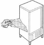
•Remove the protective PVC film on the stainless steel panels from all internal and external surfaces (fig. 2).
•Always wear protective
gloves when handling packing material and the wood base.
•Dispose of packing materials in compliance with disposal regulations applied in the country where the machine is to be installed. Never dispose of materials in the environment.
1.5General safety regulations
Failure to observe the recommendations made by the present manual will be at the entire responsibility of the machine user. The main safety regulations are as follows:
-do not touch the machine with moist or wet hands or feet;
-never operate the machine while barefoot;
-do not insert screwdrivers, cooking utensils or any other object between the guards and moving parts;
-before performing cleaning or routine maintenance operations, disconnect the machine from the power supply;
-never pull on the power cable to disconnect the machine from the power supply.
4
2. INSTALLATION
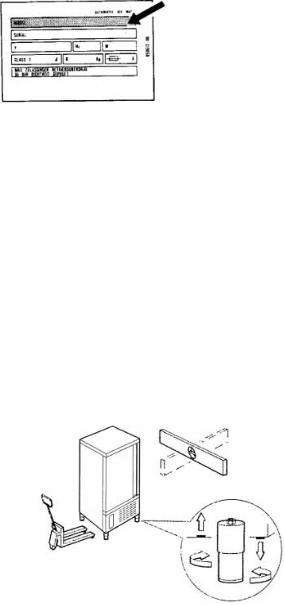
2.1Data plate information
•Check that the data specified on the plate corresponding to the characteristics of the power supply (V, kW, Hz, phases and power available).
•The dataplate with appliance specifications is located at the rear exterior of the machine
and/or on the electrical boards (fig. 3). The setup of individual units and the installation of condensers are subject to the fire-safety regulations
of the country in which the machine is installed; seek all necessary advice from the local firefighting authorities. Bear in mind that the intervention of safety valves or plug fuses in the refrigerating circuit will lead to the immediate discharge of refrigerant into the environment.
2.2Positioning
•The machine must be installed in complete compliance with safety regulations, procedures and standing laws.
•Position the machine in the allocated site.
•Adjust the machine feet by turning the foot clockwise until the appliance is perfectly level. In the case of particularly heavy equipment, use appropriate lifting means.
(fig. 4).
•If the appliance is not perfectly level, correct operation and condensate flow-off will not be
assured.
AVOID
•direct exposure to sunlight;
•closed sites with high temperatures and poor air circulation;
•installing the machine near sources of heat
Installation Clearance Requirements
All Cabinets:
12” clearance above top
12” clearance on sides and rear Remote condensing units for T40 models.
24” clearance above top
6” clearance on sides and rear
2.3 Ambient temperature and air circulation
For air-cooled appliances, the maximum ambient temperature for operation is 90°F / 32°C. Correct operation cannot be guaranteed at higher temperatures. The machine may operate safely to a maximum temperature of 100°F / 38°C. Remote condensing units may be installed indoors next to the unit or within 25 ft. Consult Delfield if placement will be greater than 25
ft. away. Remote condensing units may also be installed outdoors but require a U.L. listed enclosure which is supplied as an option from Delfield. Sufficient air circulation must be guaranteed at all times.
2.4 Electrical connections
A dedicated thermal-magnetic circuit breaker compliant with established regulations must be installed on the appliance power line.
• Connected electrical cables must correspond to the technical data (as specified on electrical drawings provided by the installation technician).
Connect the ground conductor to an efficient ground system.
THE MANUFACTURER DECLINES ALL LIABILITY AND GUARANTEE OBLIGATIONS IN THE EVENT OF INJURY TO PERSONS OR DAMAGE TO EQUIPMENT AND OBJECTS DUE TO INCORRECT INSTALLATION AND/OR FAILURE TO COMPLY WITH STANDING INSTALLATION REGULATIONS.
5
2.6 Condensate drainage connection
For T40 models fit a condensate water drainage hose with a minimum diameter of 1” . Provide a waste pipe with a trap with a diameter of at least 1 1/2” at floor level.
2.7T40 Information for the installation technician
Before starting up the machine, check that it has been correctly installed.
1.Check that there are no gas leaks from brazed joints made during installation.
2.Check that the pipes connecting the condenser to the remote condensing unit have been well insulated.
3.Check all wiring connections.
4.Check electrical input.
5.Check the standard pressure in the refrigerant system.
6.Perform at least one blast freezing cycle (to the SET temperature) and one manual defrosting cycle. In the event that the appliance or
the remote condensing unit have not been transported in a vertical position (e.g. on the back) or have been overturned during
installation works, allow at least 4 hours before starting up the equipment.
2.8Safety and control systems
•Door microswitch: shuts down fan operation in the cabinet when the door is opened.
•General fuses: protect the power circuit against short circuiting and overloads.
•Compressor heat relay: intervenes in the event of overloads or operating faults.
•Safety pressure switch: intervenes in the event of excessive pressure in the refrigerant circuit.
•Plug fuses: intervene in the event of high pressure or operating fault in the safety pressure switch (see above).
•Chamber temperature control: operated by the electronic board by means of a probe inside the cabinet.
•Temperature control end defrost cycle: controlled by the electronic board by means of the probe in the evaporator.
2.9Appliance disposal
After the useful life of the appliance has been realized, be sure to demolish and dispose of the machine in compliance with the regulations applied in the country of installation, particularly in regards to refrigerant gas and compressor lubricant oil.
6
T5/T14D DELFIELD2.10PROCEDURADoor HingePER LAReversalOTAZIONE DELLAProcedurePORTA
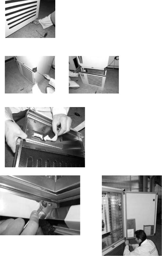
DOOR ROTATION PROCEDURE
1.Removeimu vere4laboltspre afromd’ariathefrontaleair intakesvitandopanelle 4bottomviti delle edgecerniere. lato inferiore Remove the air front intake panel unscrewing the 4 screws of inferior hinge
2.AprireOpen lathepresaair intaked’aria frontalepanel usingfacendothlevaleverconasunacascciaviterewdriversu entrambion bothi latisides. Open the air intake panel making a lever with a screwdriver on both sides
3.ScollegareDisconnectil connettorethe data cablesd lla scheda. pulsanti Remove the connector from the push buttons card
4. Remove the two lower hinge bolts.
4.Svitare le 2 viti che fissano la cerniera inferiore |
7 |
|
Unscrew the 2 bolts that fix the inferior hinge |
||
|
5..RimuovereRemove thela portachillerdell’abbattitoredoor. Remove the chiller door
6.6Remove.Ri uoverethelarightcernieratop superiorehinge. Rotatedestraitruotarla180º anddi 180°installedit on the left top side of the chiller. installarla sul lato sinistro dell’abbattitore
Remove the right top hinge and rotate it of 180° and provide to install it on the left top side of chiller
8
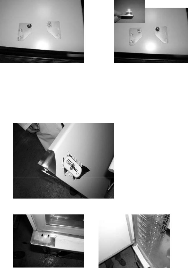
Lower right |
Lower left hinge |
Cerniera inferiore destra |
Cerniera inferiore sinistra(in |
hinge |
(left hinge |
|
dotazione) |
Lower right hinge |
supplied as |
Low r left hinge |
|
|
(l ft hinge as accessory) |
|
accessory) |
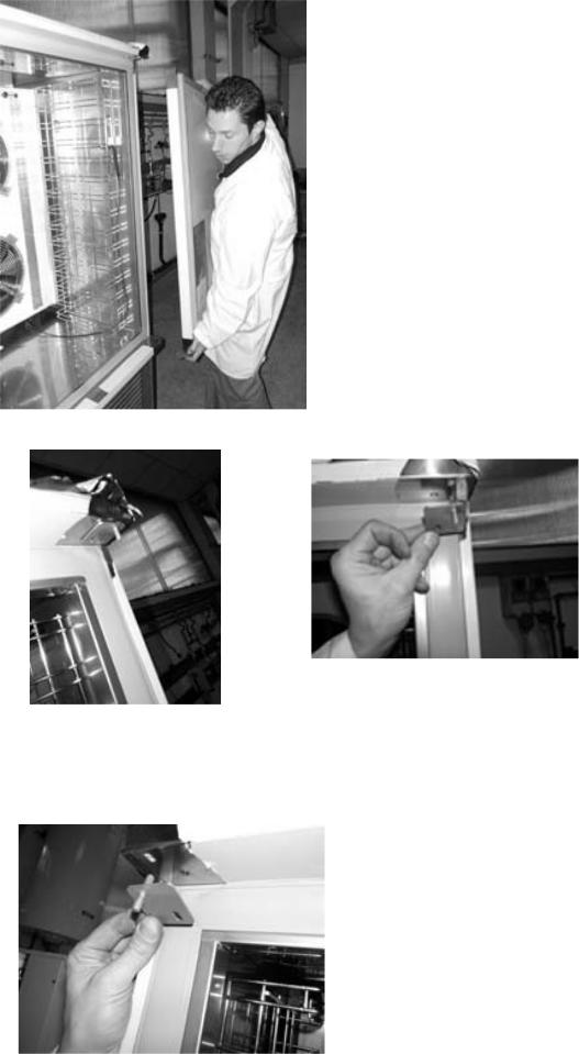
7.Move the black washer and the plastic bushing from the right hinge to the left hinge.
7.Spostare la guarnizione nera e la boccola in plastica dalla cerniera destra su quella sinistra Move the black gasket and the plastic buckle from the right hinge to the left hinge.
8.RuotareRotate thela portadoordi180º180°anded installareinsert thela cernieralower leftinferiorehinge.
Sinistra. Rotate the door of 180° and install the inferior left hinge .
9.Installarethela dportaor, fisinsertingando lathecernieratop hingeinferioreintosinistrathe prepunchedgli appositihforiles,predispostialigning the left |
9 |
|
Install the door fixing |
left inferior hinge in the predisposed holes |
|
lower hinge with theprepunched holes. |
|
|
10.FissareAdjust thela portadooreffettuandodoor hingesla r golazioneto guarantedelle acernierecorrectclosingmodoandda garsealingntireofunathecorrettagasket. Install the chiusura ed aderenza della guarnizione porta.
two lower hinge bolts.
Successivamente bloccare definitivamente le 2 cerniere.
11Reinstallare. Use puttyla targhettaknife or similaradesivatoolsultofrontalepeel offdellatheportaadhesivreinameplatestallare .presaRotate,d’ariaandsreguendoattach thele nameplate. istruzioni.
12. Reconnect the data cables.
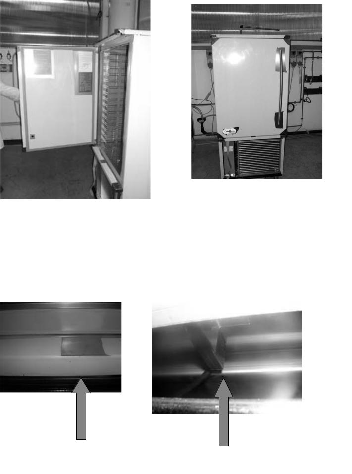
Attenzione:
13il micro. Reinstalldellatheportafrontfunzionaair intakesepanelallineato. al magnete schiumato all’interno della stessa.
In caso di allarme porta aperta regolare la posizione della porta e/o micro.(vedi ultime foto)
Attention: The door micro switch works if it’s aligned to the magnet positioned inside the door. In case the door alarms, adjust the door and/or the micro switch position. See pictures below.
Fix the door doing the hinges regulation so that to guarantee a correct closing and adherence of
the 2 screws door
.
it’s aligned |
door. |
provide to |
|
Micro switch positioned front side near the condenser
IL MICRO E’ POSIZIONATO SUL LATO FRONTALE VICINO AL CONDENSATORE 10 MICRO SWITCH POSITIONED FRONT SIDE NEAR THE CONDENSER
3. ADVICE TO ENSURE EFFICIENT APPLIANCE OPERATION
3.1 Shut-down procedures
In the event of emergency, shut down the appliance by switching off power at the main panel, by means of a breaker or power disconnect or by removing the plug from the power socket.
3.2 Operating tips
Before starting up the appliance, clean the inside of the compartment thoroughly.
3.2.1 Pre-cooling
Before using the appliance for the first time, or after a prolonged period of disuse, precool the compartment by running an empty cycle until the set operating temperature has been reached.
To ensure optimal performance without any alteration to food quality: arrange food products in such a way as to favour the circulation of cold air throughout the compartment; open the door as little as possible.
3.2.2 Loading the appliance
a)Ensure that foods to be chilled and/or frozen are separate and do not have a thickness greater than 2’’/50mm-3’’/80mm. When chilling liquids it is recommended that you do not exceed a product thickness of 1”/25mm. It is also recommended that you stir the product every 30 minutes. Do not load the appliance beyond the quantity recommended by the manufacturer.
b)Ensure that there is sufficient clearance between trays to enable free air circulation. If the appliance is not completely full, distribute the trays and foods evenly throughout the available space.
c) Position trays inside the tray compartment as far as they will go, as close as possible to the evaporator.
d)Position the core probe at the centre of the largest product or food item; make sure that the tip of the probe does not protrude or touch the tray. If you are using the probe for a liquid ensure that the probe is placed in the warmest location in the warmest pan. The probe
must be cleaned and sanitized before each new cycle (operation) to prevent inadvertent contamination.
e)Avoid covering the trays and/or containers with insulating covers or film. The more the product is insulated, the more time is required for chilling or freezing. Trays should be packaged when the product has been chilled, before being placed in storage.
11

4. DESCRIPTION OF THE VERTICAL CONTROL PANEL
2
5a
5
6
15
1
12
10
|
|
|
3 |
|
HARD |
|
|
+38 ° |
+38 ° |
0° |
4 |
|
|
|
5b |
 °C
°C
14
7
8
13
9
11
HACCP PROGRAM
12
 Loading...