


Installation, Operation, Maintenance and Parts Manual |
7D837A thru 7D849A, 7D851A, |
|
7AR79 thru 7AR88 |
|
|
Please read and save these instructions. This heater must be installed and serviced by trained gas installation and service personnel only! Read carefully before attempting to assemble, install, operate or maintain the product described. Protect yourself and others by observing all safety information. Failure to comply with instructions could result in personal injury and/or property damage! Retain these instructions for future reference.
Dayton® Tube Heaters
Description
Dayton tube heaters are gas-fired infrared heaters designed to provide comfort heat. They consist of three (3) main components: a burner control box, radiant tube, and reflector assembly. The heaters are typically suspended from the ceiling by chains and controlled by a thermostat. They can be installed either vented or unvented, and may use outside air for combustion if necessary. The radiant tube may be installed in different configurations depending on the heating requirements.
These heaters use infrared energy to heat spaces. When heat is required, the burner control box ignites a gas/air mixture and pushes the hot gases into the radiant tube. As the gases pass through the assembly, the tubing is heated and emits infrared, which is then directed toward the floor by reflectors. This is known as primary infrared and is absorbed by the floor, objects and people in the space, raising their temperatures. They in turn re-radiate this heat, known as secondary infrared, to create a comfort zone at the floor level. This is how Dayton tube heaters can heat large spaces without having to provide primary infrared for every square foot of area. However, if the goal is to spot heat a small area within a large space, only the primary infrared makes this possible. Dayton tube heaters are design certified for use in industrial and commercial buildings, such as warehouses, manufacturing plants, aircraft hangars and vehicle maintenance shops. They are not certified for residential use or where flammable gases or vapors are generally present, such as spray booths.
! WARNING
In locations used for the storage of combustible materials, signs must be posted to specify the maximum permissible stacking height to maintain the required clearances from the heater to the combustibles. Signs must either be posted
adjacent to the heater thermostats or in the absence of such thermostats, in a conspicuous location.
! WARNING
Improper installation, adjustment,
alteration, service or maintenance can cause property
damage, injury or death. Read and understand the installation, operating and maintenance instructions thoroughly before installing or servicing this equipment.
This heater must be installed and serviced by trained gas installation and service personnel only. Failure to comply could result in personal injury, asphyxiation, death, fire and/ or property damage.
For Your Safety - If you smell gas:
•Do not try to light any appliance.
•Immediately call your gas supplier from a neighbor’s phone.
•Do not touch any electrical switch.
•Follow the gas supplier’s instructions.
•Do not use any phone in your building.
•If you cannot reach your gas supplier, call the fire department.
Keep these instructions for future reference.
Form 5S6496 |
Printed in U.S.A. |
|
03460 |
|
1109/224/VCPVP |

Dayton Installation, Operation, Maintenance and Parts Manual |
7D837A thru 7D849A, 7D851A, 7AR79 thru 7AR88 |
Dayton® Tube Heaters
TABLE OF CONTENTS |
|
INTRODUCTION.................................................................................................................................................................... |
3 |
Overview......................................................................................................................................................................... |
3 |
SAFETY .............................................................................................................................................................................. |
4 |
Warning Symbols............................................................................................................................................................ |
4 |
Specific Applications........................................................................................................................................................ |
4 |
Standards, Certifications and Governmental Regulations ................................................................................................ |
5 |
Clearance to Combustibles ............................................................................................................................................. |
6 |
INSTALLATION ..................................................................................................................................................................... |
8 |
Design Considerations and Prechecks.............................................................................................................................. |
8 |
Recommended Mounting Heights................................................................................................................................... |
10 |
Hanger Placement and Suspension.................................................................................................................................. |
11 |
Optional U-Bend or Elbow Accessory Configuration......................................................................................................... |
14 |
Radiant Tube Assembly.................................................................................................................................................... |
15 |
Burner Control Box Suspension ....................................................................................................................................... |
18 |
Reflector Assembly.......................................................................................................................................................... |
19 |
Baffle Assembly and Placement....................................................................................................................................... |
21 |
Final Heater Assembly...................................................................................................................................................... |
22 |
Venting........................................................................................................................................................................... |
23 |
Combustion Air Requirements......................................................................................................................................... |
28 |
Gas Supply ..................................................................................................................................................................... |
30 |
Electrical Requirements.................................................................................................................................................... |
33 |
OPERATION........................................................................................................................................................................... |
35 |
MAINTENANCE .................................................................................................................................................................... |
36 |
Troubleshooting Guide.................................................................................................................................................... |
37 |
PARTS .............................................................................................................................................................................. |
38 |
Repair Parts Illustration.................................................................................................................................................... |
38 |
Repair Parts List............................................................................................................................................................... |
39 |
LIMITED WARRANTY ........................................................................................................................................................... |
40 |
Kit Contents
Prior to installation, verify that you have received all heater components included with your tube heater. Refer to the chart below for a list of the kit contents for your model heater. Materials not included in the kit (e.g. sheet metal screws, vent material, terminals, etc.) are the responsibility of the installer.
Filled By: |
|
5VD67A- |
5VD71A- |
5VD73A- |
5EAJ0-J2, |
5VD79A-80A, |
|
|
5VD70A |
5VD72A |
5VD78A |
5EAH3-H5 |
5EAH6-H8 |
||
|
|
|
|||||
|
Part # |
Description |
20 ft. |
30 ft. |
40ft. |
50ft. |
60ft. |
|
TP-19B |
4” Tube Hanger with Tension Spring |
3 |
4 |
5 |
6 |
7 |
|
TP-21B |
4” Tube Clamp |
2 |
3 |
4 |
5 |
6 |
|
TP-33B |
1/2” Shut-off Ball Valve/Inlet Tap |
1 |
1 |
1 |
1 |
1 |
|
TP-82 |
4” Reflector Center Support |
2 |
3 |
4 |
5 |
6 |
|
TP-83 |
24” Stainless Steel Flexible Gas Connector |
1 |
1 |
1 |
1 |
1 |
|
TP-105 |
Reflector End Cap |
2 |
2 |
2 |
2 |
2 |
|
TP-106 |
Reflector End Cap Clips |
8 |
8 |
8 |
8 |
8 |
|
THCS |
Tube Heater Chain Sets |
5 |
6 |
7 |
8 |
9 |
|
IOM |
Installation, Operation & Maintenance Manual |
1 |
1 |
1 |
1 |
1 |
|
|
|
|
|
|
|
|
2

Dayton Installation, Operation, Maintenance and Parts Manual
Models 7D837A thru 7D849A, 7D851A, 7AR79 thru 7AR88
INTRODUCTION
Overview
The intent of this manual is to provide information regarding general safety, installation, operation and maintenance of this tube heater. You must read and understand all instructions and safety warnings before installing or servicing the tube heater.
Available Models - Tube Heater Burner Box and Tube Reflector Combinations
|
Burner |
Tube & |
|
|
|
|
Combo # |
Box # |
Reflector Pkg # |
Tube Type |
Length |
BTU/H |
Gas Type |
7D837A |
5VD67A |
5VD88 |
20-4”-ALUM |
20 |
50,000 |
NAT |
|
|
|
|
|
|
|
7D838A |
5VD68A |
5VD88 |
20-4”-ALUM |
20 |
50,000 |
LP |
|
|
|
|
|
|
|
7D839A |
5VD69A |
5VD88 |
20-4”-ALUM |
20 |
75,000 |
NAT |
|
|
|
|
|
|
|
7D840A |
5VD70A |
5VD88 |
20-4”-ALUM |
20 |
75,000 |
LP |
|
|
|
|
|
|
|
7D841A |
5VD71A |
5VD89 |
30-4”-ALUM |
30 |
100,000 |
NAT |
|
|
|
|
|
|
|
7D842A |
5VD72A |
5VD89 |
30-4”-ALUM |
30 |
100,000 |
LP |
|
|
|
|
|
|
|
7D843A |
5VD73A |
5VD91 |
40-4”-ALUM |
40 |
100,000 |
NAT |
|
|
|
|
|
|
|
7D844A |
5VD74A |
5VD91 |
40-4”-ALUM |
40 |
100,000 |
LP |
|
|
|
|
|
|
|
7D845A |
5VD75A |
5VD91 |
40-4”-ALUM |
40 |
125,000 |
NAT |
|
|
|
|
|
|
|
7D846A |
5VD76A |
5VD91 |
40-4”-ALUM |
40 |
125,000 |
LP |
|
|
|
|
|
|
|
7D847A |
5VD77A |
5VD90 |
40-4”-TITAN |
40 |
150,000 |
NAT |
|
|
|
|
|
|
|
7D848A |
5VD78A |
5VD90 |
40-4”-TITAN |
40 |
150,000 |
LP |
|
|
|
|
|
|
|
7AR80 |
5EAJ0 |
5VD90 & 5EAH2 |
40-4”-TITAN & 10-4”-ALUM |
50 |
150,000 |
NAT |
|
|
|
|
|
|
|
7AR79 |
5EAJ1 |
5VD90 & 5EAH2 |
40-4”-TITAN & 10-4”-ALUM |
50 |
150,000 |
LP |
|
|
|
|
|
|
|
7AR83 |
5EAJ2 |
5VD90 & 5EAH2 |
40-4”-TITAN & 10-4”-ALUM |
50 |
175,000 |
NAT |
|
|
|
|
|
|
|
7AR81 |
5EAH3 |
5VD90 & 5EAH2 |
40-4”-TITAN & 10-4”-ALUM |
50 |
175,000 |
LP |
|
|
|
|
|
|
|
7AR87 |
5EAH4 |
5VD90 & 5EAH2 |
40-4”-TITAN & 10-4”-ALUM |
50 |
200,000 |
NAT |
|
|
|
|
|
|
|
7AR85 |
5EAH5 |
5VD90 & 5EAH2 |
40-4”-TITAN & 10-4”-ALUM |
50 |
200,000 |
LP |
|
|
|
|
|
|
|
7D849A |
5VD79A |
5VD90 & 5VD88 |
40-4”-TITAN & 20-4”-ALUM |
60 |
150,000 |
NAT |
|
|
|
|
|
|
|
7D851A |
5VD80A |
5VD90 & 5VD88 |
40-4”-TITAN & 20-4”-ALUM |
60 |
150,000 |
LP |
|
|
|
|
|
|
|
7AR84 |
5EAH6 |
5VD90 & 5VD88 |
40-4”-TITAN & 20-4”-ALUM |
60 |
175,000 |
NAT |
|
|
|
|
|
|
|
7AR82 |
5EAH7 |
5VD90 & 5VD88 |
40-4”-TITAN & 20-4”-ALUM |
60 |
175,000 |
LP |
|
|
|
|
|
|
|
7AR88 |
5EAH8 |
5VD90 & 5VD88 |
40-4”-TITAN & 20-4”-ALUM |
60 |
200,000 |
NAT |
|
|
|
|
|
|
|
7AR86 |
5EAH9 |
5VD90 & 5VD88 |
40-4”-TITAN & 20-4”-ALUM |
60 |
200,000 |
LP |
|
|
|
|
|
|
|
|
|
|
|
|
|
|
3
Dayton Installation, Operation, Maintenance and Parts Manual |
7D837A thru 7D849A, 7D851A, 7AR79 thru 7AR88 |
Dayton® Tube Heaters
SAFETY
! WARNING
Improper installation, adjustment, alteration, service or maintenance can cause property damage, serious injury or
death. Read and understand, the installation, operating and maintenance instructions thoroughly before installing or servicing this equipment. Only trained, qualified gas installation
and service personnel may install or service this equipment.
! WARNING
Not for residential use!
Do not use this heater in the home, sleeping quarters, attached garages, etc.
Safety Symbols
Safety is the most important consideration during installation, operation and maintenance of the tube heater. You will see the following symbols and signal words when there is a hazard related to safety or property damage.
! WARNING
Warning indicates a potentially hazardous situation which, if not avoided, could result in death or injury.
! CAUTION
Caution indicates a potentially hazardous situation which, if not avoided, could result in minor or moderate injury.
Applications
This is not an explosion-proof heater. No heater may be used in a Class 1 or Class 2 Explosive Environment. Consult the local Fire Marshall, fire insurance carrier and other authorities
for approval if the proposed installation is in question.
Commercial and Industrial
This tube heater is designed and certified for use in industrial and commercial buildings such as, warehouses, manufacturing
plants, aircraft hangars and vehicle maintenance shops.
NOTICE
Notice indicates a potentially hazardous situation which, if not avoided, could result in property damage.
4

Dayton Installation, Operation, Maintenance and Parts Manual
Models 7D837A thru 7D849A, 7D851A, 7AR79 thru 7AR88
Standards, Certifications and Governmental Regulations
The installation of this tube heater must comply with all applicable local, state and national specifications, regulations and building codes (contact the local building inspector and/or fire marshall for guidance) before installing the heater system.
In the absence of local codes, the installation must conform to the latest edition of the National Fuel Code ANSI Z223.1 (NFPA 54).
Refer to the following Standards and codes for application specific guidelines:
Public Garages:
The installation of this heater in public garages must conform with the Standard for Parking Structures, ANSI/ NFPA 88A (latest edition), or the Code for Motor Fuel Dispensing Facilities and Repair Garages NFPA 30A (latest edition) and must be at least 8 ft. above the floor.
Aircraft Hangars:
The installation of this heater in aircraft hangars must conform with the Standard for Aircraft Hangars, ANSI/ NFPA 409 (latest edition). The heater must be installed at least 10 ft. above the upper wing surfaces and engine enclosures of the highest aircraft which might be stored in the hangar. In areas adjoining the aircraft storage area, the heaters must be installed at least 8 ft. above the floor. The heaters must be located in areas where they will not be subject to damage by aircraft, cranes, moveable scaffolding or other objects.
High Altitude:
The installation of this tube heater is approved, without modifications, for elevations up to 6,000 ft. MSL (sea level). Contact Dayton for installations above these elevations.
Electrical:
The heater, when installed, must be electrically grounded in accordance with the National Electrical Code ANSI/NFPA 70 (latest edition). Under no circumstances is either the electrical supply line or gas supply line to provide any assistance in the suspension of the heater.
Venting:
Venting must be installed in accordance with the requirements set forth in this manual and with the NFPA 54/ANSI Z223.1 National Fuel Gas Code (latest edition).
This unit complies with or is Certified by one or more of the following organizations or Standards:
•CSA International (CSA).
•American National Standards (ANSI Z83.20b).
•National Fuel Gas Code (NFPA 54/ ANSI Z223.1).
•Occupational Safety and Health Act (OSHA).
5
Dayton Installation, Operation, Maintenance and Parts Manual |
7D837A thru 7D849A, 7D851A, 7AR79 thru 7AR88 |
Dayton® Tube Heaters
Clearance to Combustibles
! WARNING
This is not an
explosion-proof
heater. Do not
store or use flammable objects,
liquids or vapor in the vicinity of the heater. Where there is the possibility of exposure to flammable vapors or highly combustible materials, consult the local fire marshall, fire insurance carrier and other authorities for approval of the proposed installation.
Hazards
For maximum safety, the building must be evaluated for hazards before installing this heating system. A critical safety factor before installation is the clearance to combustibles.
Clearances to combustibles is defined as the minimum distance that must be maintained between the tube surface or reflector and combustible materials. It also pertains to the distance that must be maintained from moving objects (e.g. overhead doors, cranes, vehicle lifts, etc.) around the tube heater.
! WARNING
This heater should be installed so that the minimum clearances to combustibles,
as marked on the heater, will be maintained from vehicles parked below. If vehicle lifts are present, ensure that these clearances will be maintained from vehicles parked below. If vehicle lifts are present, ensure that these clearances will be maintained from the highest raised vehicle.
The following is a partial list of items to maintain clearances from:
•Gas and electrical lines
•Combustible and explosive materials
•Chemical storage areas
•Areas of high chemical fume concentrations
•Vehicle parking areas
•Vehicle lifts
•Hoists or cranes
•Storage areas with stacked materials
•Lighting
•Sprinkler heads
•Overhead doors and tracks
•Dirty, contaminated areas
! WARNING
Fire Hazard. Always maintain published clearance to combustibles. Failure to comply with the
stated clearances to combustibles could result in personal injury, death and/or property damage.
If you are unsure about the proposed installation, consult your local fire Marshall, fire insurance carrier or other qualified authorities for the approval of the proposed installation.
Safety Signs and Labels
It is important to provide warnings to alert individuals to potential hazards and safety actions. ANSI Z83.20b and CSA 2.34, require you to post a sign “specifying the maximum permissible stacking height to maintain the required published clearances from the heater to combustibles” near the heater’s thermostat or, in the absence of such thermostats, in a conspicuous location.
All safety labels must be maintained on this appliance. Contact Grainger if replacement labels are needed.
6

Dayton Installation, Operation, Maintenance and Parts Manual
Models 7D837A thru 7D849A, 7D851A, 7AR79 thru 7AR88
Clearance to Combustibles
For the safe installation of this unit, the clearance to combustibles data below (Figure 1.1) contains clearances that must be maintained. Check the heater’s rating plate to verify the minimum clearance to combustibles and gas type for your model heater.
Figure 1.1 • Clearances to Combustibles Data
0° Mounting
Angle Top
Side |
Side |
Below
45° Mounting |
|
Top |
|
||
Angle |
|
|
|
|
|
Behind
Front
|
Below |
0° w/ 1 |
Top |
Side Shield |
|
Front |
Behind |
|
Below |
0° W/ 2 Side |
Top |
Shields |
|
Side |
Side |
|
Below |
|
Mounting |
Side |
|
|
|
||
Model No. |
Angle * |
Front |
Behind |
Top |
Below |
||
Dayton - 5VD67A, 5VD68A (20’ min. to 40’ max.) |
|
|
|
|
|
|
|
50,000 BTU/H [N, P] |
0° |
9 |
|
9 |
6 |
|
47 |
7D - 837A,838A |
45° |
39 |
|
8 |
10 |
|
47 |
0° w/ 1 side shield |
0° |
29 |
|
8 |
6 |
|
47 |
0° w/ 2 side shields |
0° |
9 |
|
9 |
6 |
|
47 |
20 ft. from burner |
0° |
7 |
|
7 |
6 |
|
30 |
Dayton - 5VD69A, 5VD70A (20’ min. to 40’ max.) |
|
|
|
|
|
|
|
75,000 BTU/H [N, P] |
0° |
9 |
|
9 |
6 |
|
60 |
7D - 839A,840A |
45° |
39 |
|
8 |
10 |
|
60 |
0° w/ 1 side shield |
0° |
29 |
|
8 |
6 |
|
60 |
0° w/ 2 side shields |
0° |
9 |
|
9 |
6 |
|
60 |
20 ft. from burner |
0° |
7 |
|
7 |
6 |
|
30 |
Dayton - 5VD71A, 5VD72A, 5VD73A, 5VD74A (30’ min. to 40’ max.) |
|
|
|
||||
100,000 BTU/H [N, P] |
0° |
14 |
|
14 |
6 |
|
66 |
7D - 841A,842A,843A,844A |
45° |
39 |
|
8 |
10 |
|
66 |
0° w/ 1 side shield |
0° |
29 |
|
8 |
6 |
|
66 |
0° w/ 2 side shields |
0° |
16 |
|
16 |
6 |
|
66 |
20 ft. from burner |
0° |
7 |
|
7 |
6 |
|
30 |
Dayton - 5VD75A, 5VD76A (40’ min. to 60’ max.) |
|
|
|
|
|
|
|
125,000 BTU/H [N, P] |
0° |
20 |
|
20 |
6 |
|
76 |
7D - 845A,846A |
45° |
58 |
|
8 |
10 |
|
76 |
0° w/ 1 side shield |
0° |
42 |
|
8 |
6 |
|
76 |
0° w/ 2 side shields |
0° |
20 |
|
20 |
6 |
|
76 |
20 ft. from burner |
0° |
7 |
|
11 |
6 |
|
30 |
Dayton - 5VD77A, 5VD78A, 5VD79A, 5VD80A, 5EAJ0, 5EAJ1 (40’ min. to 60’ max.) |
|
||||||
150,000 BTU/H [N, P] |
0° |
24 |
|
24 |
6 |
|
81 |
7D-847A,848A,849A,851A, 7AR-79,80 |
45° |
58 |
|
8 |
10 |
|
81 |
0° w/ 1 side shield |
0° |
42 |
|
8 |
6 |
|
81 |
0° w/ 2 side shields |
0° |
23 |
|
23 |
6 |
|
81 |
20 ft. from burner |
0° |
11 |
|
11 |
6 |
|
44 |
Dayton - 5EAJ2, 5EAH3, 5EAH6, 5EAH7 (50’ min. to 60’ max.) |
|
|
|
|
|||
175,000 BTU/H [N, P] |
0° |
34 |
|
34 |
6 |
|
92 |
7AR - 81, 82, 83, 84 |
45° |
63 |
|
8 |
10 |
|
92 |
0° w/ 1 side shield |
0° |
50 |
|
8 |
6 |
|
92 |
0° w/ 2 side shields |
0° |
30 |
|
30 |
6 |
|
92 |
20 ft. from burner |
0° |
11 |
|
11 |
6 |
|
44 |
Dayton - 5EAH4, 5EAH5, 5EAH8, 5EAH9 (50’ min. to 60’ max.) |
|
|
|
||||
200,000 BTU/H [N, P] |
0° |
41 |
|
41 |
6 |
|
94 |
7AR - 85, 86, 87, 88 |
45° |
63 |
|
8 |
10 |
|
94 |
0° w/ 1 side shield |
0° |
54 |
|
8 |
6 |
|
94 |
0° w/ 2 side shields |
0° |
30 |
|
30 |
6 |
|
94 |
20 ft. from burner |
0° |
11 |
|
11 |
6 |
|
44 |
Minimum end clearance for all models is 12 inches. *Heaters mounted on an angle between 0° to 45° must maintain clearances posted for both 0° and 45° mounting angles; whichever is greater.
7

Dayton Installation, Operation, Maintenance and Parts Manual |
7D837A thru 7D849A, 7D851A, 7AR79 thru 7AR88 |
Dayton® Tube Heaters
Installation
Design Considerations and Prechecks
Placement of infrared tube heaters is influenced by many factors. Aside from safety factors, considerations such as the number of elbows that are allowed, maximum vent lengths, ducting of combustion air and combining vents are a few examples.
This manual, along with national, state
Heater Installation Chart
and local codes, addresses these issues. It is critical that all guidelines and instructions are followed.
To ensure a properly designed heating system, a heating layout should be developed for the correct placement of the burner control box, radiant
tubing, venting and combustion air intake ducts. Inspect and evaluate the mounting conditions, vent locations, gas supply and electrical wiring.
Refer to the chart below for the recommended distances for the model being installed.
|
|
|
Distance |
Distance |
Maximum |
|
|
|
Recommended |
Between |
Between |
Distance Between |
|
Model # |
BTU/H |
Mounting Heights |
Heaters |
Heater Rows |
Heater and Wall |
|
7D837A-7D838A |
50,000 |
9’ to 14’ |
10’ to 20’ |
20’ to 40’ |
16’ |
|
|
|
|
|
|
|
|
7D839A-7D840A |
75,000 |
11’ to 18’ |
20’ to 30’ |
30’ to 50’ |
20’ |
|
|
|
|
|
|
|
|
7D841A-7D844A |
100,000 |
13’ to 23’ |
20’ to 30’ |
30’ to 50’ |
20’ |
|
|
|
|
|
|
|
|
7D845A-7D846A |
125,000 |
14’ to 25’ |
20’ to 30’ |
30’ to 50’ |
25’ |
|
|
|
|
|
|
|
|
7D847A-7D851A, |
150,000 |
15’ to 35’ |
30’ to 40’ |
40’ to 60’ |
25’ |
|
7AR79-7AR80 |
||||||
|
|
|
|
|
||
|
|
|
|
|
|
|
7AR81-7AR84 |
175,000 |
17’ to 35’ |
30’ to 40’ |
40’ to 60’ |
30’ |
|
|
|
|
|
|
|
|
7AR85-7AR88 |
200,000 |
18’ to 40’ |
30’ to 40’ |
40’ to 60’ |
30’ |
|
|
|
|
|
|
|
When designing an infrared radiant heating system, consider the following:
•Has the building’s heat loss been evaluated?
•Does the design meet the needs of the space?
•Have all clearance to combustible situations been observed?
•Have recommended mounting heights been observed?
•Is the supply (burner) end of the heater located where more heat is required?
•Is it best to offset the heaters and/ or rotate the reflectors towards the heat zone?
•Are protective guards, side shields, ‘U’ or ‘L’ reflector covers needed?
•Does the heater require outside fresh air for combustion?
•Is the environment harsh or contaminated (requiring outside air for combustion)?
•Are chemicals or vapor a concern (requiring outside air for combustion)?
NOTE: The effective infrared surface temperature of a person or object may be diminished with wind above 5 mph. The use of adequate wind barrier(s) may be required.
NOTE: When heated, materials high in hydrocarbons (solvents, paint thinner, mineral spirits, formaldehydes, etc.) can evaporate. This may result in odors or fumes being emitted into the environment. To correct this problem, clean the area and/or introduce additional ventilation.
Heaters installed and serviced in accordance with the installation manual do not emit odors into the environment. See notice on page 28 additional information.
8

Dayton Installation, Operation, Maintenance and Parts Manual
Models 7D837A thru 7D849A, 7D851A, 7AR79 thru 7AR88
Design Scenario
A tube heater system is being installed in 70’ (L) x 40’ (W) space with 12’ ceilings. Two overhead doors are located at one end and an equipment storage area exists on one side. The calculated heat load is 300,000 BTU/H.
Figure 2.1 • Poor Design
•Two burners (150,000 BTU/H each) are placed at one end, opposite the area of highest demand (overhead doors).
•Recommended mounting heights are not observed.
•Produces an uneven heat distribution.
Figure 2.2 • Good Design
•Four burners (75,000 BTU/H each) are placed in each corner. Burner (hotter) ends direct heat to areas of highest head demand.
•Recommended mounting heights observed.
•Distributes heat more evenly.
|
70’ |
Gas Supply |
|
|
|
|
|
Doors and |
|
60’ - 150,000 BTU |
|
|
(2 total) |
|
|
tracks |
|
|
|
|
|
|
|
|
Equipment storage |
|
|
Too Cold |
|
Too Hot |
40’ |
|
Poor Design |
|
|
Doors and |
|
|
|
tracks |
|
|
|
|
70’ |
|
|
Gas Supply |
|
Doors and |
20’ - 75,000 BTU |
|
tracks |
(4 total) |
|
|
Equipment storage |
|
|
Better Heat Distribution |
40’ |
|
Good Design |
|
Doors and |
|
|
tracks |
|
|
|
Sidewall Vent (2 total) |
|
9
Dayton Installation, Operation, Maintenance and Parts Manual |
7D837A thru 7D849A, 7D851A, 7AR79 thru 7AR88 |
Dayton® Tube Heaters
Recommended Mounting Heights
Model |
BTU Range |
Recommended Mounting Heights |
Coverage Straight Config. (LxW) |
Coverage U-Tube Config. (LxW) |
Distance Between Heater Rows (Ft.) Dim. A |
Distance Between Heater Rows (Ft.) Dim. B |
Max. Distance Between Heaters and Wall (Ft.) Dim C |
|
|
|
|
|
|
|
|
20 ft. |
50 MBH |
10’ - 16’ |
20’ x 12’ |
12’ x 12’ |
10’ - 20’ |
20’ - 40’ |
16’ |
|
75 MBH |
12’ - 20’ |
22’ x 15’ |
12’ x 12’ |
20’ - 30’ |
30’ - 50’ |
18’ |
|
|
|
|
|
|
|
|
30 ft. |
100 MBH |
13’ - 20’ |
33’ x 18’ |
N/A |
20’ - 30’ |
30’ - 50’ |
20’ |
|
|
|
|
|
|
|
|
40 ft. |
100-125 MBH |
13’ - 25’ |
44’ x 21’ |
23’ x 17’ |
20’ - 30’ |
30’ - 50’ |
20’ |
|
150 MBH |
16’ - 30’ |
45’ x 26’ |
24’ x 20’ |
30’ - 40’ |
40’ - 60’ |
25’ |
|
|
|
|
|
|
|
|
50 ft. |
150-200 MBH |
16’ - 30’ |
56’ x 30’ |
N/A |
30’ - 40’ |
40’ - 60’ |
25’ |
|
|
|
|
|
|
|
|
60 ft. |
150-200 MBH |
17’ - 40’ |
67’ x 34’ |
34’ x 26’ |
30’ - 40’ |
40’ - 60’ |
25’ |
|
|
|
|
|
|
|
|
NOTE: Factory recommended mounting heights are listed as a guideline. If infrared heaters are mounted to low or to high, they may result in heat discomfort or lack of heat. It is generally recommended to
observe the recommended mounting heights to optimize comfort conditions. However, certain applications such
as spot heating, freeze protection, outdoor patio heating or very high ceilings may result in the heaters
being mounted outside of the factory recommended mounting heights. Clearances to combustibles must always be maintained.
Figure 2.3 • Recommended Mounting Heights and Distances - see chart above for dimensions.
 Dimension A

Dimension B
Distance between
heater rows  Dimension A
Dimension C
Maximum distance between heater and wall
Dimension C |
Maximum |
distance |
between |
heater |
and wall |
10
Dayton Installation, Operation, Maintenance and Parts Manual
Models 7D837A thru 7D849A, 7D851A, 7AR79 thru 7AR88
Hanger Placement and Suspension
Suspension of the heater must conform to applicable codes referenced in the Safety section and these instructions.
1.Lay radiant tubing out in the following order. Position tubes in their approximate locations. Figure 2.4.
•10 ft. primary combustion chamber.
•Radiant emitter tubes.
IMPORTANT! 150 MBH models must use the 10 ft. titanium alloy treated combustion chamber as the first tube connected to the burner control box. The combustion chamber has an orange identification sticker located on the swaged end of the tube.
2.Mark locations for hanging points. Figure 2.4 Chart.
NOTE: If the available hanging points do not allow for the recommended spacing (or if an alternative hanging method is utilized) then additional hangers may be necessary.
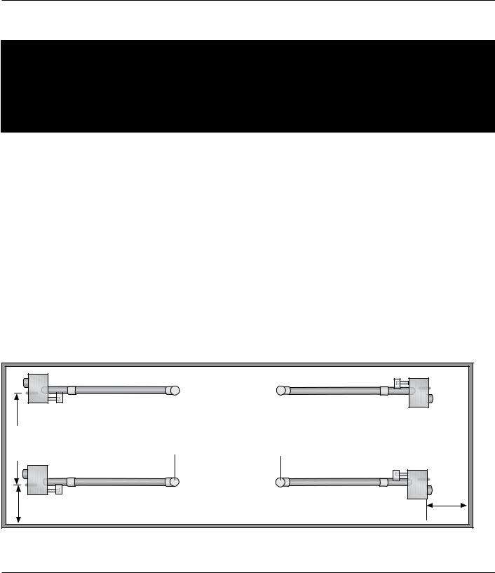
•The spacing between the burner control box mounting brackets and the first hanger should be approximately 2’-4”.
•The space between the first two hangers placed on the first tube should be approximately 8’-10”.
•The space between hangers thereafter, one per tube, should be approximately 9’-8”.
! WARNING
Failure to maintain the published
clearance to combustibles may
result in fire and/or explosion, property damage, serious injury or death. Always maintain clearances and post signs where needed.
! WARNING
Improper suspension of the heater may
result in collapse and being crushed.
Always suspend the appliance from a permanent part of the building structure that can support the total weight and force of the heater.
11

Dayton Installation, Operation, Maintenance and Parts Manual |
7D837A thru 7D849A, 7D851A, 7AR79 thru 7AR88 |
Dayton® Tube Heaters
Hanger Placement and Suspension
Figure 2.4 • Heater Suspension Layout
NOTE: A sticker identifying the combustion chamber(s) is located on the swaged end of the tube(s).
Hanging
Point
Burner Control Box |
|
Hanging Points |
10” |
|
- |
|
8’ |
|
|
Hanging
Point
Hanging Point
-8” 9’
-8” 9’
Radiant Emitter
Tube(s)
Radiant Emitter Tube
-4” 2’
16” Burner 

Tube
10 ft. Primary Combustion Chamber
Igniter/Sensor Box
Burner Control Box
Heater Mounting Requirements and Weights
Model |
Dimension Straight Config. |
Hanging Points |
Control Box Hanging Points |
Shipping Weight |
Chain Set Qty. Straight Config. |
Chain Set Qty. U-Tube Config. |
Optional Brass Knuckles (P/N: 5VD54) |
Optional Single Mount Bracket (P/N: 5VD85) U Config. Only. |
|
|
|
|
|
|
|
|
|
20 ft. |
21’-8” |
3 |
2 |
120 lbs. |
5 |
6 |
3 |
2 |
|
|
|
|
|
|
|
|
|
30 ft. |
31’-4” |
4 |
2 |
160 lbs. |
6 |
N/A |
4 |
N/A |
|
|
|
|
|
|
|
|
|
40 ft. |
41’-0” |
5 |
2 |
190 lbs. |
7 |
8 |
5 |
3 |
50 ft. |
50’-8” |
6 |
2 |
235 lbs. |
8 |
N/A |
6 |
N/A |
|
|
|
|
|
|
|
|
|
60 ft. |
60’-4” |
7 |
2 |
265 lbs. |
9 |
10 |
7 |
4 |
|
|
|
|
|
|
|
|
|
12
 Loading...