


Operating Instructions & Parts Manual |
3E358B and 3E359B |
|
|
Please read and save these instructions. Read carefully before attempting to assemble, install, operate or maintain the product described. Protect yourself and others by observing all safety information. Failure to comply with instructions could result in personal injury and/or property damage! Retain instructions for future reference.
Dayton® Portable
Oil-Fired Heaters
Description
Dayton Models 3E358B and 3E359B are 350,000 Btu/Hr heaters and 600,000 Btu/ Hr heaters, respectively. These heaters use only Kerosene or No. 1 fuel oil for combustion and electricity to run the motor. They are primarily intended for well ventilated indoor or outdoor temporary heating of buildings under construction, alteration, or repair (Read General Safety Information section carefully). They may be used in agricultural, industrial, and commercial environments. Products of combustion are vented into the area being heated.
Unpacking
1.Remove all protective packing applied to heater for shipment.
2.Remove heater from shipping container.
3.Check heater for any shipping damage. If heater is damaged, promptly inform dealer where you bought heater.
Figure 1 – Model 3E358B |
® |
Figure 2 – Model 3E359B |
ARL LOGO |
|
G 004 |
General Specifications
|
Model 3E358B |
Model 3E359B |
Output Rating ......................................... |
350,000 Btu/Hr |
600,000 Btu/Hr |
Amperage at 120V 60 Hz ....................... |
7.1 |
11.0 |
Fuel .......................................................... |
Kerosene or No. 1 fuel |
Kerosene or No. 1 fuel |
Fuel Tank Capacity .................................. |
30.0 U.S. Gallons |
36.0 U.S. Gallons |
Fuel Consumption .................................. |
2.5 U.S. Gallons/Hr |
4.0 U.S. Gallons/Hr |
Motor ....................................................... |
1725 RPM |
1725 RPM |
Hot Air Output (CFM) ............................. |
1,350 |
3,300 |
Fuel Pump Pressure ................................ |
100 psi |
110 psi |
Heater Weight with Fuel ....................... |
390 Lb |
550 Lb |
Heater Weight without Fuel .................. |
180 Lb |
285 Lb |
Spark Plug Gap ....................................... |
.075 inches |
.075 inches |
Form 5S2514
Printed in U.S.A. |
® |
|
03430
0602/094/VCPVP
Version B - For Reduction |
G016.J |
Dayton Operating Instructions and Parts Manual |
3E358B and 3E359B |
Dayton® Portable
Oil-Fired Heaters
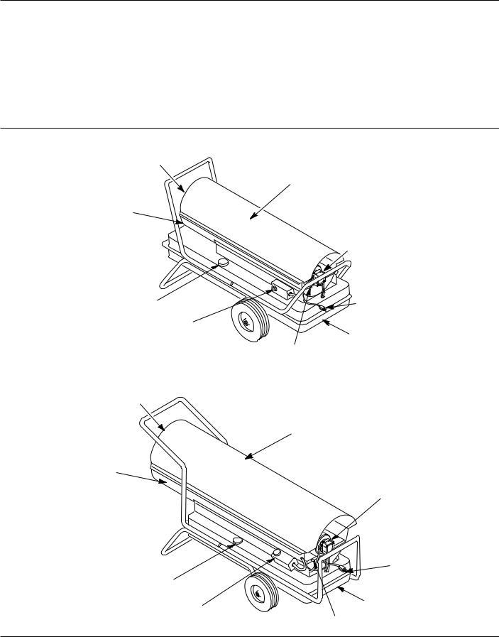
Product Identification
Hot Air Outlet
Lower Shell
Fuel Cap
Thermostat
Figure 3 – Model 3E358B
Hot Air Outlet
Lower Shell
Fuel Cap
Thermostat
Figure 4 – Model 3E359B
Upper Shell
Motor and Pump
Assembly
Power Cord
Fuel Tank
Flame-Out Control
Reset Button
Upper Shell
Motor and Pump
Assembly
Power Cord
Fuel Tank
Flame-Out Control
Reset Button
2
Dayton Operating Instructions and Parts Manual
Models 3E358B and 3E359B
General Safety Information
Make certain you read and understand all warnings. Keep these instructions for reference. They are your guide to safe and proper operation of this heater.
Safety information appears throughout these instructions. Pay close attention to them. Below are definitions for the safety information listed throughout this manual.
Under this heading, installation, operat-
ing and maintenance procedures or practices will be found that, if not carefully followed, WILL result in IMMEDIATE serious personal injury or death.
Under this heading, installation, operating, and maintenance proce-
dures or practices will be found that, if not carefully followed, COULD result in severe personal injury or death.
Under this heading, installation, operat-
ing, and maintenance procedures or practices will be found that, if not carefully followed, MAY result in minor personal injury, product, or property damage.
IMPORTANT: Not every possible circumstance that might involve a hazard can be anticipated. The warnings in this manual and on tags or decals affixed to the unit are therefore not all-inclusive. If a procedure, work method, or operating technique not specifically recommended by Dayton is used, you must make sure it is safe for you and others. You should also ensure that equipment will not be damaged or made unsafe by the operating or maintenance method you choose.
Carbon monoxide poisoning may lead
to death!
Carbon monoxide poisoning: Early signs of carbon monoxide poisoning resemble the flu, with headaches, dizziness, and/or nausea. If you have these signs, the heater may not be working properly. Get fresh air at once! Have heater serviced. Some people are more affected by carbon monoxide than others. These include pregnant women, people with heart or lung disease or anemia, those under the influence of alcohol, and those at high altitudes.
Improper use of this heater can
cause serious injury or death from burns, fire, explosion, electrical shock, and carbon monoxide poisoning.
Make certain you read and understand all warnings. Keep these instructions for reference. They are your guide to safe and proper operation of this heater.
• Use only Kerosene or No. 1 fuel
oils to avoid risk of fire or explosion. Never use gasoline, naphtha, paint thinners, alcohol, or other highly flammable fuels.
•Fueling
a)Personnel involved with fueling shall be qualified and thoroughly familiar with the manufacturer's instructions and applicable federal, state, and local regulations regarding the safe fueling of heating units.
b)Only the type of fuel specified on the heater's data plate shall be used.
c)All flame, including the pilot light, if any, shall be extinguished and the heater allowed to cool, prior to fueling.
d)During fueling, all fuel lines and fuel-line connections shall be inspected for leaks. Any leaks shall be repaired prior to returning the heater to service.
e)At no time shall more than one day's supply of heater fuel be stored inside a building in the vicinity of the heater. Bulk fuel storage shall be outside the structure.
f)All fuel storage shall be located a minimum of 25 feet from heaters, torches, welding equipment, and similar sources of ignition (exception: the fuel reservoir integral with the heater unit).
g)Whenever possible, fuel storage shall be confined to areas where floor penetrations do not permit fuel to drip onto or be ignited by a fire at lower elevation.
h)Fuel storage shall be in accordance with the federal, state, or local authority having jurisdiction.
•Never use heater where gasoline, paint thinner, or other highly flammable vapors are present.
•Follow all local ordinances and codes when using heater.
•Use only in well-vented areas. Provide at least three square feet of fresh, outside air for each 100,000 Btu/Hr of rating. This heater produces carbon monoxide, which is listed by the State of California as a reproductive toxin under Proposition 65.
•Use only in places free of flammable vapors or high dust content.
•Use only with the electrical voltage and frequency specified on model plate.
®
3
Dayton Operating Instructions and Parts Manual |
3E358B and 3E359B |
Dayton® Portable
Oil-Fired Heaters
General Safety Information |
• |
Never use heater in living or sleeping |
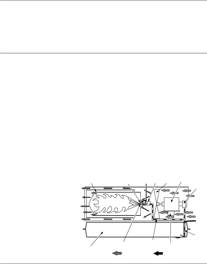
THE AIR SYSTEM |
|
|||||
(Continued) |
|
|
areas. |
|
The motor turns the fan. The fan |
||||
|
• |
Never block air inlet (rear) or air |
|||||||
• |
Heater must be grounded. Use only a |
pushes air into and around the combus- |
|||||||
|
outlet (front) of heater. |
|
tion chamber. This air is heated and |
||||||
|
properly grounded three-wire exten- |
• |
Never move, handle, refuel, or |
||||||
|
provides a stream of clean, hot air. |
||||||||
|
sion cord. Plug into grounded outlet |
||||||||
|
|
service a hot, operating, or plugged- |
THE IGNITION SYSTEM |
||||||
|
only. |
|
|
||||||
|
|
|
in heater. |
|
|||||
|
|
|
|
|
The electronic ignitor sends voltage to |
||||
• |
Never start heater when combustion |
• |
Never attach duct work to front or |
||||||
|
chamber is hot or if fuel has accumu- |
the spark plug. The spark plug ignites |
|||||||
|
|
rear of heater. |
|
||||||
|
lated in combustion chamber. |
• Warning to New York City Residents For |
the fuel and air mixture. |
||||||
|
|
|
|
|
|
|
|||
• |
Never use gasoline, crankcase |
|
Use Only At Construction Sites in accor- |
THE FLAMEOUT CONTROL SYSTEM |
|||||
|
drainings, naphtha, paint thinners, |
|
dance with applicable NYC codes under |
This system causes the heater to shut |
|||||
|
alcohol, or other highly flammable |
|
NYC Board of Standards and appeals |
||||||
|
|
down if the flame goes out. It also |
|||||||
|
fuels. |
|
|
calendar number 62-59-SA. |
|||||
|
|
|
allows the fan to continue running |
||||||
• |
Never leave a heater plugged in |
|
|
|
|||||
THEORY OF OPERATION |
|
after normal shutdown of heater. This |
|||||||
|
without adult supervision if children |
|
|||||||
|
|
|
|
cools the combustion chamber. |
|||||
|
or animals are likely to be present. |
THE FUEL SYSTEM |
|
||||||
|
|
|
|
|
|
||||
|
|
|
|
|
|
|
|
||
• |
Heaters used in the vicinity of tarpau- |
The motor turns the fuel pump. The |
|
|
|
|
|||
|
lins, canvas, or similar enclosure |
|
|
|
|
||||
|
fuel pump pulls fuel from the fuel |
|
|
|
|
||||
|
materials shall be located a safe |
|
|
|
|
||||
|
tank. The fuel pump pushes fuel |
|
|
|
|
||||
|
distance from such materials. The |
|
|
|
|
||||
|
through a filter and a solenoid valve |
|
|
|
|
||||
|
recommended minimum safe distance |
|
|
|
|
||||
|
and out the burner head nozzle. A fine |
|
|
|
|
||||
|
is 10 feet. It is further recommended |
|
|
|
|
||||
|
that these enclosure materials be of a |
mist of fuel is sprayed into the combus- |
|
|
|
|
|||
|
fire retardant nature. These enclosure |
tion chamber. |
|
|
|
|
|
||
|
materials shall be securely fastened to |
|
|
|
|
|
|
|
|
|
prevent them from igniting or from |
|
|
|
Burner |
Solenoid |
Motor |
||
|
upsetting the heater due to wind |
|
Combustion |
|
|||||
|
|
Spark Plug |
Head |
Valve |
Fan |
||||
|
action. |
|
|
Chamber |
|
|
|
|
Fuel Pump/ |
|
|
|
|
|
|
|
|
Fuel Filter |
|
|
|
|
|
|
|
|
|
|
|
• |
Minimum heater clearances from |
|
|
|
|
|
|
|
|
|
combustibles: |
|
Clean |
|
|
|
|
|
|
|
Outlet: 8 Ft. |
Sides: 4 Ft. |
|
|
|
|
|
||
|
Heated |
|
|
|
|
Cool |
|||
|
Top: 4 Ft. |
Rear: 4 Ft. |
Air Out |
|
|
|
|
||
|
|
|
|
|
Air In |
||||
|
|
|
|
|
|
|
|||
|
|
|
|
|
|
|
|
|
|
• |
Locate heater on a stable and level |
|
|
|
|
|
|
|
|
|
surface while hot or running or a fire |
|
|
|
|
|
|
|
|
|
may occur. |
|
|
|
|
|
|
|
Fuel |
|
|
|
|
|
|
|
|
|
|
• |
When moving or storing heater, keep |
|
|
|
|
|
|
Pickup |
|
|
heater in a level position or fuel |
|
|
|
|
|
|
Line |
|
|
|
|
|
|
|
|
|
||
|
spillage may occur. |
|
|
|
|
|
|
|
Fuel |
• |
Keep children and animals away from |
|
|
|
|
|
|
||
|
|
|
|
|
|
Filter |
|||
|
heater. |
|
|
|
|
Fuel Line To |
|
||
|
|
|
|
Nozzle |
|
|
|||
|
|
|
|
|
Solenoid |
|
Electronic |
||
• |
Unplug heater when not in use. |
|
Fuel Tank |
|
|
||||
|
|
Valve |
|
Ignitor |
|
||||
• |
This heater has a built-in thermostat. |
|
|
Air for Combustion |
|
Fuel |
|
||
|
Plugged-in heater may start at |
|
|
|
|
||||
|
|
|
and Heating |
|
|
|
|||
|
anytime. |
|
Figure 5 - Cross Section Operational View |
|
|
|
|||
4
Dayton Operating Instructions and Parts Manual
Models 3E358B and 3E359B
General Safety Information
(Continued)
FUELS
Use only kerosene, or No. 1 fuel oil to
avoid risk of fire or explosion. Never use gasoline, naphtha, paint thinners, alcohol, or other highly flammable fuels.
Do not use heavy fuels such as No. 2 fuel oil or No. 2 Diesel. Using heavy fuels will result in:
•clogged fuel filter and nozzle
•carbon buildup on spark plug
•the need of nontoxic anti-icer in fuel during very cold weather
IMPORTANT: Use a KEROSENE ONLY container. Be sure storage container is clean. Foreign matter such as rust, dirt, or water will cause the flameout control to shut down heater. Foreign matter may also require you to clean fuel system often.
VENTILATION
Follow the minimum fresh, outside
air ventilation requirements. If proper fresh, outside air ventilation is not provided, carbon monoxide poisoning can occur. Provide proper fresh, outside air ventilation before running heater.
FRESH AIR OPENING REQUIREMENTS
|
Square Feet |
Heater Size |
Opening |
350,000 Btu/Hr |
10.5 |
600,000 Btu/Hr |
18.0 |
NOTE: If you use more than one heater, provide extra fresh air. Provide a fresh air opening of at least three square feet for each 100,000 Btu/Hr rating.
Operation
Review and understand the
warnings in the General Safety Information section. They are needed to safely operate this heater. Follow all local codes when using this heater.
TO START HEATER
1.Follow all ventilation and safety information.
2.Locate heater to provide maximum circulation of the heated air. Follow all location requirements noted in
Safety Information, pages 3 and 4.
3.Fill fuel tank with Kerosene or No. 1 fuel oil.
4.Attach fuel cap.
5.Set thermostat dial to desired temperature.
NOTE: Thermostat setting must be higher than surrounding air temperature.
6.Plug power cord of heater into three-prong, grounded extension cord. Extension cord must be at least six feet long.
Use only a threeprong, grounded extension cord. Use cord with proper
wire size to assure 120 volt operation. See Extension Cord Wire Size Requirements below.
EXTENSION CORD WIRE SIZE
REQUIREMENTS
•6 to 100 feet long, use 14 AWG rated cord
•101 to 200 feet long, use 12 AWG rated cord
•201 to 300 feet long, use 10 AWG rated cord
•301 to 400 feet long, use 8 AWG rated cord
•401 to 500 feet long, use 6 AWG rated cord
7.Plug extension cord into standard 120 volt/60 hertz, three-hole, grounded outlet.
®
5
Dayton Operating Instructions and Parts Manual |
3E358B and 3E359B |
Dayton® Portable
Oil-Fired Heaters
Operation (Continued)
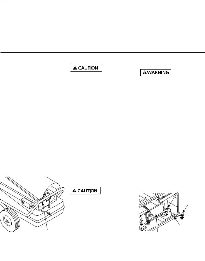
8.The motor will start when extension cord is plugged into outlet. The heater should ignite at once. If heater does not ignite, restart heater. To restart heater, wait 60 seconds, then push in flameout control reset button. Flameout control reset button is at rear of heater near power cord (See Figure 6).
NOTE: If starting heater for first time, you may need to prime the pump. If equipped, slightly open the bleeder valve of the pump to allow air to escape. Quickly close the valve once fuel is seen. Wipe up excess fuel. If equipped with canister fuel filter, remove the canister bottom and fill with fuel. Reassemble filter. Wipe up any excess fuel. You may also have to do this after taking heater out of storage.
Flame-Out
Control Reset
Button
Figure 6 - Flame-Out Control Reset Button
TO STOP HEATER
Never unplug heater while heater is running. Heater must go
through purge cycle. The purge cycle cools the combustion chamber. Damage to heater can occur if combustion chamber is not cooled. Do not restart heater until purge cycle is complete.
1.Turn thermostat dial to lowest temperature setting. This will cause heater flame to go out. The motor will continue to run during the purge cycle. This allows the fan to cool the combustion chamber. When the purge cycle is finished, the motor will stop. Do not unplug heater until purge cycle is finished.
2.Unplug extension cord from outlet.
3.To temporarily stop heater, set thermostat at a temperature lower than air around heater. Heater will cycle back on if air temperature around heater matches thermostat setting.
TO RESTART HEATER
Do not restart heater until purge
cycle is finished. The purge cycle cools the combustion chamber.
1.Wait until purge cycle is finished after stopping heater.
2.Repeat steps under To Start Heater, page 5.
OPERATION WITH PORTABLE GENERATOR
Before operating heater or any
appliance from a portable generator, verify that generator has been properly connected to earth ground. Improper grounding or failure to ground generator can result in electrocution if a ground fault occurs. Refer to owner’s manual supplied by generator manufacturer for proper grounding procedures.
The operating voltage range of the heater is 108 to 132 Volts (120 Volts +/- 10%). Prior to plugging heater into generator the output voltage should be verified (if generator is equipped with the automatic idle feature, the output voltage should be measured with the generator running at full speed). If the voltage does not measure in this range the heater should not be plugged into the generator.
Refer to Operation on page 5 for starting, stopping, and resetting heater procedures.
Ground Lug
Copper or Brass
Grounding
Point
Ground Wire
(#10 AWG -
Alternator Stranded-
Copper)
Figure 7 - Typical Generator Grounding Method (Generator construction may vary from that shown)
6

Dayton Operating Instructions and Parts Manual
Models 3E358B and 3E359B
Maintenance |
Air Deflector |
Fan Blade |
Never service heater while it is
plugged in, operating, or hot. Severe burns and electrical shock can occur.
UPPER SHELL REMOVAL
1.Remove screws along each side and top of heater using 5/16" nut-driver. These screws attach upper and lower shells together (See Figure 8).
2.Lift upper shell off.
Upper Shell
Figure 8 - Upper Shell Removal,
Model 3E359B
FAN BLADES AND AIR DEFLECTORS
1.Remove upper shell (See Figure 8).
2.Clean fan blades and air deflectors with clean, soft cloth moistened with Kerosene or solvent (See Figure 9).
3.Dry fan blades and air deflectors thoroughly.
4.Replace upper shell.
Figure 9 - Fan Blades and Air Deflectors
SPARK PLUG
1.Remove upper shell (See Figure 8).
2.Remove spark plug wire from spark plug (See Figure 10).
3.Remove spark plug from burner head using 13/16" open-end wrench (See Figure 10).
4.Replace spark plug if damaged or heavily coated with carbon.
5.Clean and regap spark plug electrodes to .075 inch (See Figure 11).
6.Install spark plug in burner head.
7.Attach spark plug wire to spark plug.
8.Replace upper shell.
Burner Head
Spark Plug
Spark Plug
Wire
Figure 10 - Spark Plug Removal
 .075 inch
FUEL FILTERS
TANK FUEL FILTER
1.Disconnect fuel lines from pump and fuel filter canister, if equipped, with 7/16" wrench (See Figure 12).
2.Carefully pry fuel filter loose from fuel tank with flat end of screwdriver.
3.Inspect fuel filter for water or dirt.
4.Rinse fuel filter and fuel lines with clean Kerosene.
5.Replace fuel filter into fuel tank.
6.Connect fuel lines to pump and fuel filter canister, if equipped.
Fuel Pump |
Fuel Lines |
(Filter Under |
|
Cover) |
|
Fuel
Filter
Figure 12 - Removing Tank Fuel Filter
Figure 11 - Spark Plug Gap
®
7
Dayton Operating Instructions and Parts Manual |
3E358B and 3E359B |
Dayton® Portable
Oil-Fired Heaters
Maintenance (Continued)
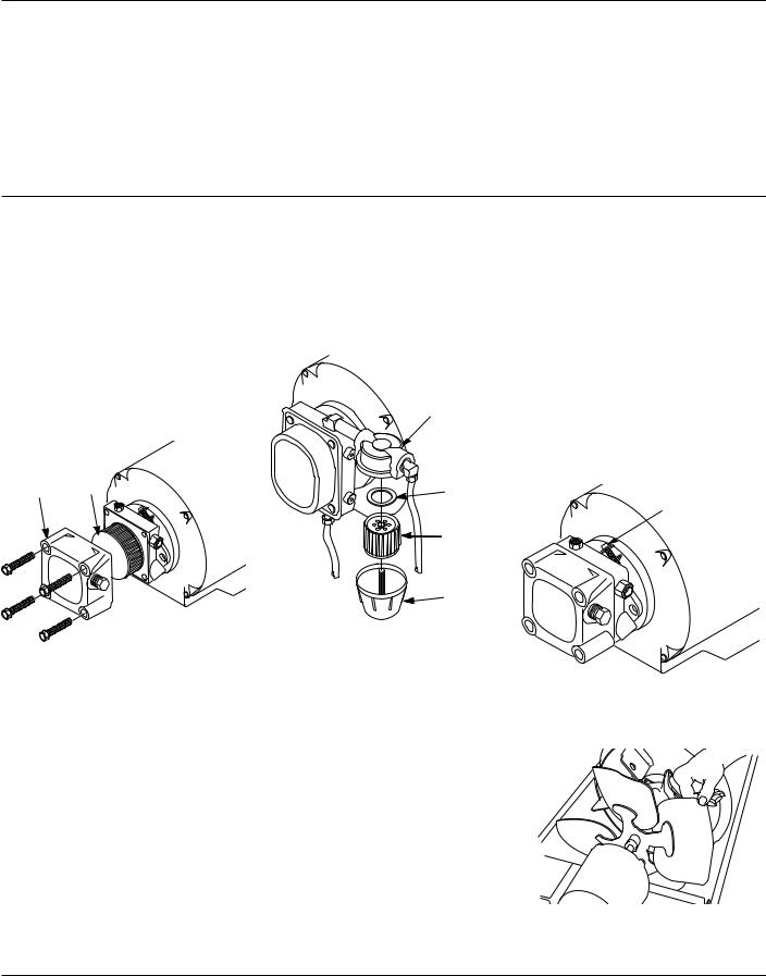
FOR HEATERS WITH FUEL FILTER INTERNAL TO PUMP
1.Remove pump cover to access filter.
2.Rinse and wipe inside of pump cover and dry with clean cloth.
3.Rinse fuel filter in clean kerosene or blow compressed air from inside out.
4.Reassemble and tighten securely. Check for leaks.
Pump Fuel
Cover Filter
6.Rinse fuel filter in clean Kerosene.
7.Put clean fuel filter and gasket back in canister bottom.
8.Screw canister bottom into canister top.
9.Tighten securely. Check for leaks.
Canister
Top
Gasket
Fuel Filter
Canister
Bottom
Figure 14 - Fuel Pump Filter and Canister
Figure 13 - Fuel Pump and Filter
PUMP
(Procedure if pump is binding)
1.Remove upper shell (See Figure 8, page 7).
2.Loosen hex screw on flange clamp at rear of motor with 5/16" nut-driver (See Figure 15).
3.Turn fan with hand (See Figure 16).
4.If fan turns freely, tighten screw on flange clamp.
5.If fan does not turn freely, replace pump.
6.Replace upper shell.
Hex Screw On
Flange Clamp
FOR HEATERS WITH FUEL FILTER/ CANISTER EXTERNAL TO PUMP
1.Unscrew canister bottom from canister top with Channellock pliers.
2.Remove fuel filter and gasket from canister bottom (See Figure 14).
3.Inspect canister bottom and fuel filter for water or dirt.
4.Rinse canister bottom in clean Kerosene.
5.Wipe inside of canister bottom dry with clean cloth.
Figure 15 - Location of Screw on Flange Clamp
Figure 16 - Turning Fan with Hand
8
 Loading...