


Operating Instructions & Parts Manual |
2E510E, 2E511E, 3E218E, and 3E219D |
|
|
Please read and save these instructions. Read carefully before attempting to assemble, install, operate or maintain the product described. Protect yourself and others by observing all safety information. Failure to comply with instructions could result in personal injury and/or property damage! Retain instructions for future reference.
Dayton® Portable
Oil-Fired Heaters
Description
Dayton Models 2E510E, 2E511E, 3E218E, and 3E219D are 40,000 to 150,000 Btu/Hr heaters. These heaters use only Kerosene or No. 1 fuel oil for combustion and electricity to run the motor. They are primarily intended for indoor and outdoor temporary heating of well-ventilated buildings under construction, alteration, or repair. They may be used in agricultural, industrial, and commercial environments.
Unpacking
1.Remove all packing items supplied with heater for shipment.
2.Remove all items from carton.
3.Check heater for any shipping damage. If heater is damaged, promptly inform dealer where you bought heater.
Figure 1 – Models 2E510E and 2E511E |
Figure 2 – Models 3E218E and 3E219D |
|
® |
Specifications
GENERAL SPECIFICATIONS
|
Output |
|
Fuel Tank Capacity |
Fuel Consumption |
|
Model |
Rating Btu |
Fuel |
(U.S. Gallons) |
(U.S. Gallons/Hr.) |
Motor RPM |
2E510E |
40,000 |
Kerosene or No. 1 fuel oil |
3.0 |
0.3 |
1725 |
2E511E |
60,000 |
Kerosene or No. 1 fuel oil |
5.0 |
0.44 |
1725 |
3E218E |
110,000 |
Kerosene or No. 1 fuel oil |
9.0 |
0.8 |
3450 |
3E219D |
150,000 |
Kerosene or No. 1 fuel oil |
13.5 |
1.1 |
3450 |
|
Hot Air |
Air Pump |
Shipping Weight |
Heater Weight |
Model |
Output (CFM) |
Pressure (PSI) |
(Pounds) |
(Pounds - without fuel) |
2E510E |
170 |
3.0 |
32 |
28 |
2E511E |
180 |
3.4 |
33 |
29 |
3E218E |
490 |
5.3 |
58 |
49 |
3E219D |
550 |
5.4 |
67 |
56 |
Form 5S1792
Printed in U.S.A. |
® |
03430
0898/157/VCPVP
Version B - For Reduction |
G016.J |
Dayton Operating Instructions and Parts Manual |
2E510E, 2E511E, 3E218E, and 3E219D |
Dayton® Portable
Oil-Fired Heaters
Specifications (Continued)
ELECTRICAL SPECIFICATIONS
|
|
Amperage |
Model |
Electrical Input |
(during normal run) |
2E510E |
120 Volt/60 Hertz |
2.0 |
2E511E |
120 Volt/60 Hertz |
2.0 |
3E218E |
120 Volt/60 Hertz |
3.6 |
3E219D |
120 Volt/60 Hertz |
3.6 |
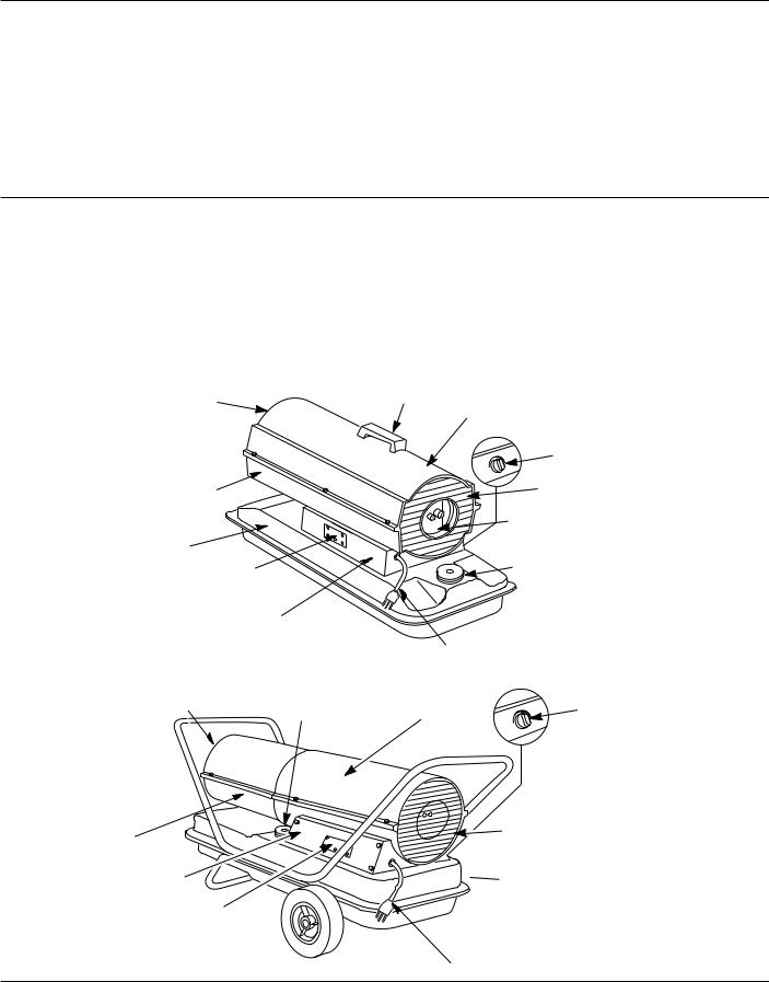
Product Identification
Hot Air
Outlet
Lower
Shell
Fuel Tank
Ignition Control Assembly (on inside of side cover)
Side Cover
Figure 3 – Models 2E510E and 2E511E
Hot Air Outlet
Fuel Cap
Lower Shell
Side Cover
Ignition Control Assembly (on inside of side cover)
Figure 4 – Models 3E218E and 3E219D
Handle
Upper Shell
Thermostat
Knob
Fan Guard
Air Filter
End Cover
Fuel
Cap
Power Cord |
|
|
Upper Shell |
Thermostat |
|
Knob |
||
|
Fan
Guard
 Fuel
Fuel
Tank
Power Cord
104447
2
Dayton Operating Instructions and Parts Manual
Models 2E510E, 2E511E, 3E218E, and 3E219D
General Safety Information
Make certain you read and understand all warnings. Keep these instructions for reference. They are your guide to safe and proper operation of this heater.
Safety information appears throughout these instructions. Pay close attention to them. Below are definitions for the safety information listed throughout this manual.
Under this heading, installation, operat-
ing and maintenance procedures or practices will be found that, if not carefully followed, WILL result in IMMEDIATE serious personal injury or death.
Under this heading, installation,
operating, and maintenance procedures or practices will be found that, if not carefully followed, COULD result in severe personal injury or death.
Under this heading, installation, operat-
ing, and maintenance procedures or practices will be found that, if not carefully followed, COULD result in minor personal injury, product or property
IMPORTANT: Every possible circumstance that might involve a hazard cannot be anticipated. The warnings in this manual and on tags or decals affixed to the unit are therefore not all-inclusive. If a procedure, work method, or operating technique not specifically recommended by Dayton is used, you must make sure it is safe for you and others. You should also ensure that equipment will not be damaged or made unsafe by the operating or maintenance method you choose.
Carbon monoxide poisoning may lead
to death! Some people are more affected by carbon monoxide than others. Early signs of carbon monoxide poisoning resemble the flu, with headaches, dizziness, and/or nausea. If you have these signs, the heater may not be operating properly, or the areas may not be sufficiently ventilated. Get fresh air at once! Have heater serviced.
Improper use of this heater can
cause serious injury or death from burns, fire, explosion, electrical shock, and carbon monoxide poisoning.
Make certain you read and understand all warnings. Keep these instructions for reference. They are your guide to safe and proper operation of this heater.
• Use only Kerosene or No. 1 fuel
oil to avoid risk of fire or explosion. Never use gasoline, naphtha, paint thinners, alcohol, or other highly flammable fuels.
•Fueling
a)Personnel involved with fueling shall be qualified and thoroughly familiar with the manufacturer's instructions and applicable federal, state, and local regulations regarding the safe fueling of heating units.
b)Only the type of fuel specified on the heater's data plate shall be used.
c)All flame, including the pilot light, if any, shall be extinguished and the heater allowed to cool, prior to fueling.
d)During fueling, all fuel lines and fuel-line connections shall be inspected for leaks. Any leaks shall be repaired prior to returning the heater to service.
e)At no time shall more than one day's supply of heater fuel be stored inside a building in the vicinity of the heater. Bulk fuel storage shall be outside the structure.
f)All fuel storage shall be located a minimum of 25 feet from heaters, torches, welding equipment, and similar sources of ignition (exception: the fuel reservoir integral with the heater unit).
g)Whenever possible, fuel storage shall be confined to areas where floor penetrations do not permit fuel to drip onto or be ignited by a fire at lower elevation.
h)Fuel storage shall be in accordance with the federal, state, or local authority having jurisdiction.
•Never use heater where gasoline, paint thinner, or other highly flammable vapors are present.
•Follow all local ordinances and codes when using heater.
•Use only in well-vented areas. Provide at least three square feet of fresh, outside air for each 100,000 Btu/Hr of rating. This heater produces carbon monoxide, which is listed by the State of California as a reproductive toxin under Proposition 65.
•Use only in places free of flammable vapors or high dust content.
•Use only with the electrical voltage and frequency specified on model plate.
•Use only a three-prong, grounded extension cord.
®
104447
3
Dayton Operating Instructions and Parts Manual |
2E510E, 2E511E, 3E218E, and 3E219D |
Dayton® Portable
Oil-Fired Heaters
General Safety Information |
Theory of Operation |
Fuels |
|
|||||
(Continued) |
|
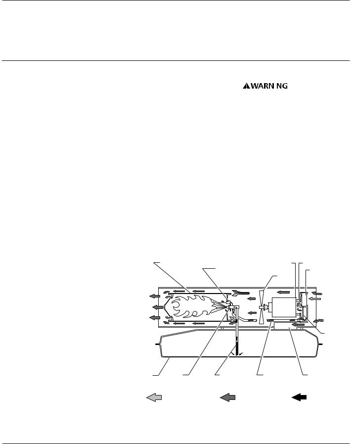
THE FUEL SYSTEM |
|
|
|
Use only Kerosene |
||
|
|
|
|
|||||
|
|
|
|
|
|
|||
• |
Heaters used in the vicinity of |
The air pump forces air through the |
|
|
|
or No. 1 fuel oil to |
||
|
|
|
||||||
avoid risk of fire or explosion. Never |
||||||||
|
tarpaulins, canvas, or similar |
air line. The air is then pushed |
||||||
|
use gasoline, naphtha, paint thinners, |
|||||||
|
enclosure materials shall be located |
through the burner head nozzle. This |
alcohol, or other highly flammable |
|||||
|
a safe distance from such materials. |
air causes fuel to lift from the tank. A |
fuels. |
|
||||
|
The recommended minimum safe |
fine mist of fuel is sprayed into the |
Do not use heavy fuels such as No. 2 |
|||||
|
distance is 10 feet. It is further |
|||||||
|
combustion chamber. |
fuel oil or No. 2 Diesel. Using heavy |
||||||
|
recommended that these enclosure |
|||||||
|
THE AIR SYSTEM |
fuels will result in: |
|
|||||
|
materials be of a fire retardant |
|
||||||
|
|
|
|
|
|
|||
|
nature. These enclosure materials |
The motor turns the fan. The fan |
• clogged fuel filter and nozzle |
|||||
|
shall be securely fastened to |
pushes air into and around the |
• carbon build-up on spark plug |
|||||
|
prevent them from igniting or from |
combustion chamber. This air is heated |
• the need of non-toxic anti-icer in |
|||||
|
upsetting the heater due to wind |
and provides a stream of clean, hot air. |
||||||
|
fuel during very cold weather |
|||||||
|
action. |
|
||||||
|
|
THE IGNITION SYSTEM |
||||||
• |
Minimum heater clearances from |
IMPORTANT: Use a KEROSENE ONLY |
||||||
The ignition control assembly provides |
||||||||
|
combustibles: |
|
container. Be sure storage container is |
|||||
|
|
power to the ignitor. This ignites the |
||||||
|
Outlet: 8 Ft. |
Sides: 4 Ft. |
clean. Foreign matter such as rust, dirt, or |
|||||
|
fuel/air mixture in the combustion |
|||||||
|
water will cause the flame-out control to |
|||||||
|
Top: 4 Ft. |
Rear: 4 Ft. |
||||||
|
chamber. |
|||||||
|
shut down heater. Foreign matter may also |
|||||||
• |
Locate heater on a stable and level |
|||||||
THE FLAME-OUT CONTROL SYSTEM |
||||||||
require you to clean fuel system often. |
||||||||
|
surface while hot or running or a fire |
|||||||
|
This system causes the heater to shut |
|
|
|
|
|||
|
may occur. |
|
|
|
|
|
||
• |
When moving or storing heater, keep |
down if the flame goes out. |
|
|
|
|
||
|
|
|
|
|
||||
|
heater in a level position or fuel |
Combustion Chamber |
|
|
|
|
||
|
spillage may occur. |
|
Motor |
Air Pump |
||||
• |
Keep children and animals away |
Ignitor |
|
|
|
Air Intake |
||
|
|
Fan |
Filter |
|||||
|
|
|
|
|
||||
from heater.
• Unplug heater when not in use.
• This heater is equipped with a |
Clean |
|
|
|
Cool |
|
|
thermostat, heater may start anytime. |
|
|
|
Air In |
|
|
Heated |
|
|
|
|
|
• |
Never use heater in living or sleep- |
Air Out |
|
|
|
|
|
|
|
|
|
||
|
ing areas. |
|
|
|
|
|
• |
Never block air inlet (rear) or air |
|
|
|
|
Air |
|
|
|
|
Output |
||
|
outlet (front) of heater. |
|
|
|
|
|
|
|
|
|
|
Filter |
|
• |
Never move, handle, refuel, or |
|
|
|
|
|
|
service a hot, operating, or plugged- |
|
|
|
|
|
|
in heater. |
|
|
|
|
|
• |
Never attach duct work to front or |
Fuel |
Nozzle |
Fuel |
Air Line |
Ignition Control |
|
rear of heater. |
|||||
|
Tank |
|
Filter |
To Burner |
Assembly |
|
|
|
|
Air For Fuel |
|
Air For Combus- |
Fuel |
|
|
|
System |
|
tion and Heating |
|
|
|
|
|
|
||
Figure 5 - Cross Section Operational View
104447
4
Dayton Operating Instructions and Parts Manual
Models 2E510E, 2E511E, 3E218E, and 3E219D
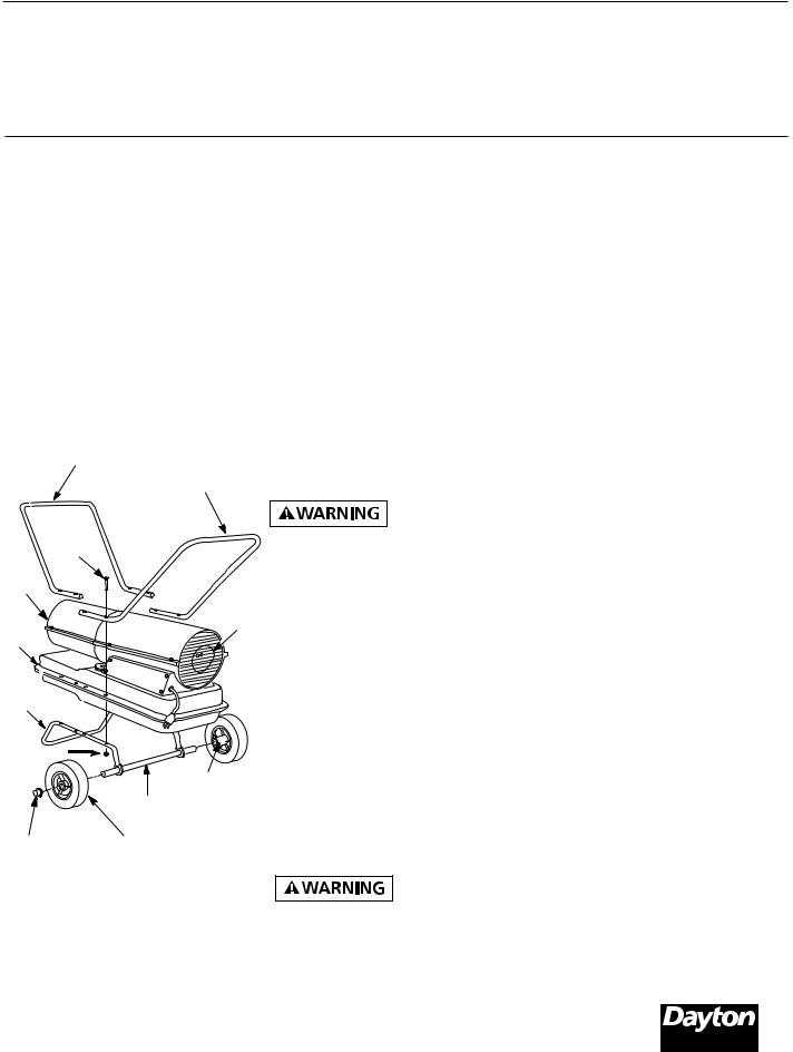
Assembly |
|
IMPORTANT: When installing wheels, |
TO START HEATER |
||
(For Models 3E218E and 3E219D Only) |
point extended hub of wheels toward |
1. Follow all ventilation and safety |
|||
wheel support frame (See Figure 6). |
|||||
|
|
|
information. |
||
These models are furnished with |
2. Place cap nuts on axle ends. Gently |
||||
2. Locate heater to provide maximum |
|||||
wheels and handles. Wheels, handles, |
tap with hammer to secure. |
||||
circulation of the heated air. Follow |
|||||
and the mounting hardware are found |
3. Place heater on wheel support |
||||
all location requirements noted in |
|||||
in the shipping carton. |
|||||
frame. Make sure air inlet end (rear) |
General Safety Information, page 3. |
||||
|
|
|
|||
TOOLS NEEDED |
|
of heater is over wheels. Line up |
|||
|
3. Fill fuel tank with Kerosene or No. 1 |
||||
• |
MEDIUM PHILLIPS SCREWDRIVER |
holes on fuel tank flange with holes |
|||
fuel oil. |
|||||
on wheel support frame. |
|||||
• 3/8" Open or Adjustable Wrench |
|
||||
4. Place front handle and rear handle on |
4. Attach fuel cap. |
||||
• |
Hammer |
|
top of fuel tank flange. Insert screws |
5. Turn thermostat knob clockwise to |
|
1. Slide axle through wheel support |
through handles, fuel tank flange, |
the HIGH position. |
|||
and wheel support frame. Attach nut |
|
||||
|
frame. Install wheels on axle. |
6. Plug power cord of heater into |
|||
|
finger tight after inserting each screw. |
||||
|
|
|
three-prong, grounded extension |
||
|
|
|
5. After inserting all screws, tighten |
||
|
|
|
cord. Extension cord must be at least |
||
|
|
|
nuts firmly. |
||
|
|
|
six feet long. |
||
|
|
|
|
||
|
Front Handle |
|
EXTENSION CORD WIRE SIZE |
||
|
|
Rear Handle |
Ventilation |
REQUIREMENTS |
|
|
|
• 6 to 10 feet long, use 18 AWG |
|||
|
|
|
Follow the mini- |
||
|
|
|
rated cord. |
||
|
|
|
mum fresh, outside |
||
|
|
|
• 11 to 100 feet long, use 16 AWG |
||
|
Screw |
|
air ventilation requirements. If proper |
||
|
|
fresh, outside air ventilation is not |
rated cord. |
||
Hot Air |
|
provided, carbon monoxide poisoning |
• 101 to 200 feet long, use 14 AWG |
||
|
can occur. Provide proper fresh, |
||||
Outlet |
|
rated cord. |
|||
|
|
Air |
outside air ventilation before running |
||
Fuel |
heater. |
7. Plug extension cord into standard |
|||
Tank |
Inlet |
Provide a fresh air opening of at least |
120 Volt/60 hertz, three-hole, |
||
Flange |
|
||||
|
three square feet for each 100,000 |
grounded outlet. |
|||
|
|
|
|||
|
|
|
Btu/Hr rating. Provide extra fresh air if |
Note: Ignitor will preheat for five |
|
|
|
|
more heaters are being used. |
||
|
|
|
seconds, then heater will start. |
||
Wheel Support |
|
Example: A 150,000 Btu/Hr heater |
|||
|
8. Adjust thermostat knob to the |
||||
Frame |
|
requires one of the following: |
|||
|
|
|
desired setting. |
||
|
|
|
• a two-car garage door (16-foot-wide |
||
|
Nut |
|
Note: A cold heater may affect the |
||
|
|
opening) raised 3.5 inches |
|||
|
|
Extended |
• a single-car garage door (9-foot- |
thermostat setting. Further adjust- |
|
|
|
ments may be needed until the heater |
|||
|
|
Hub |
wide opening) raised 6 inches |
||
|
|
cycles at the desired setting. This |
|||
|
|
Axle |
• two, 30-inch windows raised 11 |
||
|
|
|
thermostat is a general-heating |
||
|
|
|
inches |
||
Cap Nut |
|
control. It is not intended for precise |
|||
Wheel |
|
||||
Operation |
temperature control. |
||||
|
|
|
|||
Figure 6 - Wheel and Handle Assembly, |
TO STOP HEATER |
||||
Review and |
|||||
Models 3E218E and 3E219D Only |
Unplug extension cord from outlet. |
||||
|
|
|
understand the |
||
|
|
|
TO RESET HEATER |
||
|
|
|
warnings in the General Safety |
||
|
|
|
Information section. They are needed |
1. Unplug extension cord from outlet |
|
|
|
|
|
||
to safely operate this heater. Follow |
and wait 10 seconds (two minutes if |
|
all local codes when using this heater. |
||
heater has been running). |
||
|
||
|
2. Repeat steps under To Start Heater. |
|
|
|
|
104447 |
® |
|
|
5
Dayton Operating Instructions and Parts Manual |
2E510E, 2E511E, 3E218E, and 3E219D |
Dayton® Portable
Oil-Fired Heaters
Maintenance
Never service heater while it is
plugged in, operating, or hot. Severe burns and electrical shock can occur.
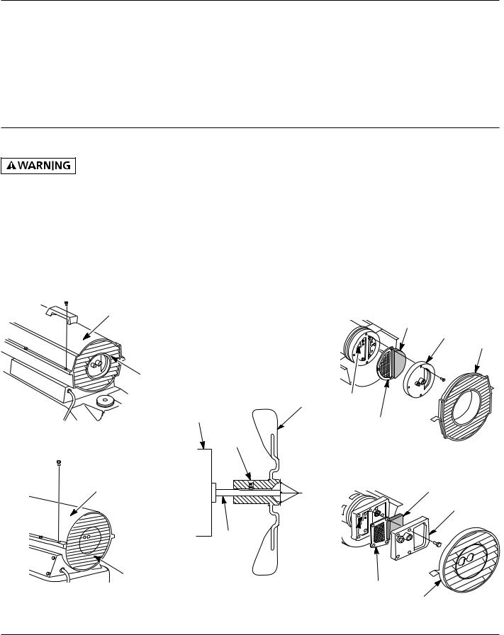
UPPER SHELL REMOVAL
1.Remove screws along each side of heater using 5/16" nut-driver. These screws attach upper and lower shells together (See Figures 7 and 8).
2.Lift upper shell off.
3.Remove fan guard.
Upper Shell
Fan Guard
Figure 7 - Upper Shell Removal, Models 2E510E and 2E511E
FAN
IMPORTANT: Remove fan from motor shaft before removing motor from heater. The weight of the motor resting on the fan could damage the fan pitch.
1.Remove upper shell.
2.Use 1/8" Allen wrench to loosen setscrew which holds fan to motor shaft.
3.Slip fan off motor shaft.
4.Clean fan using a soft cloth moistened with Kerosene or solvent.
5.Dry fan thoroughly.
6.Replace fan on motor shaft. Place fan hub flush with end of motor shaft (See Figure 9).
7.Place setscrew on flat of shaft. Tighten setscrew firmly (40-50 inch-pounds).
8.Replace fan guard and upper shell.
Fan
Motor
Setscrew
Upper |
|
Shell |
Flush |
|
Motor
Shaft
Fan Guard
Figure 9 - Fan Cross Section
Figure 8 - Upper Shell Removal, Models 3E218E and 3E219D
AIR OUTPUT, AIR INTAKE, AND LINT FILTERS
1.Remove upper shell (See Figures 7 and 8).
2.Remove filter end cover screws using 5/16" nut-driver (See Figures 10 and 11).
3.Remove filter end cover.
4.Replace air output and lint filters.
5.Wash and dry with soap and water or replace air intake filter.
6.Replace filter end cover.
7.Replace fan guard and upper shell.
IMPORTANT: Do not oil filters.
Air Intake Filter
Filter End Cover
Fan Guard
Lint Filter
Air Output Filter
Figure 10 - Air Output, Air Intake, and Lint Filters, Models 2E510E and 2E511E
Air Intake Filter
Filter End Cover
Lint
Filter
Air Output
Filter
Fan Guard
Figure 11 - Air Output, Air Intake, and Lint Filters, Models 3E218E and 3E219D
104447
6

Dayton Operating Instructions and Parts Manual
Models 2E510E, 2E511E, 3E218E, and 3E219D
Maintenance (Continued)
PUMP PRESSURE ADJUSTMENT
1.Remove pressure gauge plug from filter end cover (See Figure 12).
2.Install accessory pressure gauge (Part Number HA1180) (See Figure 13).
3.Start heater (See Operation, page 5). Allow motor to reach full speed.
4.Adjust pressure. Turn relief valve to right to increase pressure. Turn relief valve to left to decrease pressure. See specification chart below for correct pressure for each model.
|
Pump |
Model |
Pressure |
2E510E |
3.0 psi |
2E511E |
3.4 psi |
3E218E |
5.3 psi |
3E219D |
5.4 psi |
5.Remove pressure gauge. Replace pressure gauge plug in filter end cover.
Pressure
Gauge Plug Relief
Valve
Figure 12 - Pressure Gauge Plug
Removal
Fuel Filter
Pressure
Gauge
PRESSURE ADJUST |
P |
Figure 13 - Adjusting Pump Pressure
FUEL FILTER
1.Remove side cover screws using 5/16" nut-driver.
2.Remove side cover.
3.Pull upper fuel line off fuel filter neck (See Figure 14).
4.Carefully pry bushing, fuel filter, and lower fuel line (Models 3E218E and 3E219D only) out of fuel tank (See Figure 15).
5.Wash fuel filter with clean fuel and replace in tank.
6.Attach upper fuel line to fuel filter neck.
7.Replace side cover.
Side |
Upper Fuel Line |
|
Cover |
||
|
Figure 14 - Fuel Filter Removal, Models 2E510E and 2E511E
Fuel Filter, Bushing, and
Lower Fuel Line
Upper
Fuel
Line
Side
Cover
Figure 15 - Fuel Filter Removal, Models 3E218E and 3E219D
®
104447
7
Dayton Operating Instructions and Parts Manual |
2E510E, 2E511E, 3E218E, and 3E219D |
Dayton® Portable
Oil-Fired Heaters
Maintenance (Continued)
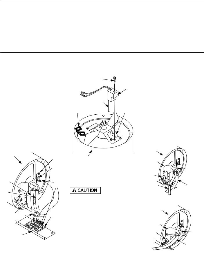
IGNITOR
1.Remove upper shell and fan guard (See page 6).
2.Remove fan (See page 6).
3.Remove 4 side cover screws with a 5/16" nut driver. Remove side cover (See Figures 14 and 15).
4.Disconnect ignitor wires (yellow for 3E218E and 3E219D, gray for 2E510E and 2E511E) from ignition control assembly (See Figure 16). Pull the ignitor wires up through the hole in the lower shell.
5.Disconnect fuel line hose and air line hose. Remove photocell from photocell bracket (See Figure 16).
Combustion |
Nozzle |
|
Chamber |
||
Adapter |
||
|
||
|
Bracket |
|
|
Ignitor |
|
Air |
|
|
Line |
Ignitor |
|
Hose |
||
|
Wires |
|
Fuel |
|
|
Line |
|
|
Hose |
|
|
Photocell |
Ignition |
|
Control |
||
Bracket |
||
Assembly |
||
|
||
Photocell |
|
|
Assembly |
|
|
Side Cover |
|
Figure 16 - Disconnecting Ignitor Wires from Ignition Control Assembly
6.Remove combustion chamber. Stand combustion chamber on end with nozzle adapter bracket on top (See Figure 17).
Ignitor Screw/Washer
Assembly
|
Ignitor |
|
Ignitor |
|
Element |
|
Nozzle |
Photocell |
Adapter |
Bracket |
Bracket |
|
Nozzle Adapter |
Combustion |
Bracket Opening |
Chamber |
|
Figure 17 - Ignitor Replacement
7.Remove ignitor screw with a 1/4" nut driver. Carefully remove ignitor from nozzle adapter bracket.
Do not bend or strike ignitor
element. Handle with care.
8.Carefully remove replacement ignitor from styrofoam packing.
9.Carefully guide ignitor into opening in nozzle adapter bracket. Do not strike ignitor element. Attach ignitor to nozzle adapter bracket with screw using a 1/4" nut driver (See Figure 17). Torque 8 to 15 in. lbs. Do not over torque.
10. Replace combustion chamber.
11.Route the ignitor wires back down through the hole in the lower shell. Connect wires to the ignition control assembly.
12.Replace side cover (See Figures 14 and 15).
13.Connect and route fuel line hose and air line hose to nozzle adapter assembly. See Fuel and Air Line Replacement and Proper Routing, page 9.
14.Replace photocell in photocell bracket. Route wires as shown in Figure 18, 19, or 20.
15.Replace fan (See page 6).
16.Replace fan guard and upper shell (See page 6).
Combustion
Chamber
Burner
Strap
|
Nozzle/ |
Photocell |
Adapter |
Assembly |
|
Bracket |
|
Air Line |
Fuel Line |
Hose |
Hose |
Figure 18 - Removing Air and Fuel Line Hoses, (40, and 60,000 Btu/Hr Models Only)
Combustion
Chamber
Burner |
|
Strap |
|
Photocell |
|
Bracket |
Nozzle/ |
|
Adapter |
Air Line |
Assembly |
|
|
Hose |
Fuel Line |
|
|
|
Hose |
Figure 19 - Removing Air and Fuel Line Hoses, (110,000 Btu/Hr Model Only)
104447
8
 Loading...