


Operating Instructions & Parts Manual
3WY47, 3W735B, 3W736C, 3WY44, 3TE27A, 3WY45, and 3WY46
Please read and save these instructions. Read carefully before attempting to assemble, install, operate or maintain the product described. Protect yourself and others by observing all safety information. Failure to comply with instructions could result in personal injury and/or property damage! Retain instructions for future reference.
Dayton® Professional-
Duty Electric Generators
Description
Dayton professional-duty generators are rugged and compact to provide dependable, trouble-free service. The alternators are brushless with revolving fields. Honda gasoline engines provide long life under heavy use. Overhead valves (OHV) provide high performance with lower fuel consumption. These engines are governed to maintain engine speed of 3600 RPM under load. 3600 RPM engine speed provides 120/240V, 60 Hz power. Additional features include circuit breaker protection, spark-arresting muffler (except Model 3WY47), large fuel tank, and oil alert system. Models 3WY45, 3WY46, and 3WY47 include electric starter.
Unpacking
1.Remove generator from carton.
2.Remove any protective packaging applied to generator for shipment.
3.Check for loose or missing parts. Check for shipping damage. If any parts are missing or damaged, promptly inform dealer where you bought generator.
4.Battery cables are supplied for Models 3WY45, 3WY46, and 3WY47 only. These cables are in a separate bag inside generator carton. You must install these cables to engine. See “Battery,” page 8 for installation instructions.
Model 3WY47 only: handles and top cover packaged separately inside generator carton. You must install these parts.
Figure 1 – Model 3W735B
Figure 2 – Models 3W736C, 3WY44, 3WY46, 3TE27A, and 3WY45 |
Figure 3 – Model 3WY47 |
Form 5S4175
Printed in U.S.A. |
® |
03430
0803 / 253 / VCPVP
Version B - For Reduction |
G016.J |

Dayton Operating Instructions and Parts Manual |
3WY47, 3W735B, 3W736C, 3WY44, 3TE27A, 3WY45, and 3WY46 |
Dayton® Professional-Duty
Electric Generators
Specifications
ELECTRICAL SPECIFICATIONS
|
Rated |
Rated Amperage |
Rated Amperage |
Model |
Wattage* |
120V |
240V |
3W735B |
2,200 |
18.3 |
— |
3W736C |
4,000 |
33.3 |
16.7 |
3WY44 |
5,000 |
41.7 |
20.8 |
3WY46 |
5,000 |
41.7 |
20.8 |
3TE27A |
6,000 |
50 |
25 |
3WY45 |
7,000 |
60 |
30 |
3WY47 |
10,000 |
83.3 |
41.7 |
* Single-phase, 1.0 power factor
NOTE: Ratings apply to SAE standard conditions. Reduce ratings 3 1/2% for each 1000 feet above sea level and 1% for each 10°F rise above 60°F.
GENERAL SPECIFICATIONS
|
Honda |
Honda |
|
Fuel |
Fuel Tank |
Oil Alert |
Electric |
|
Weight |
Model |
Engine H.P. |
Model |
|
Type |
Capacity |
System |
Start |
|
(pounds) |
3W735B |
5.5 |
GX160K1VX |
|
Gasoline |
3.9 qt. |
Yes |
No |
|
85 |
3W736C |
8 |
GX240K1VA |
|
Gasoline |
5 gal. |
Yes |
No |
|
139 |
3WY44 |
9 |
GX270VA |
|
Gasoline |
8 gal. |
Yes |
No |
|
173 |
3WY46 |
9 |
GX270VDE |
|
Gasoline |
8 gal. |
Yes |
Yes |
|
175 |
3TE27A |
11 |
GX340K1VA |
|
Gasoline |
8 gal. |
Yes |
No |
|
191 |
3WY45 |
13 |
GX390K1VXE |
|
Gasoline |
8 gal. |
Yes |
Yes |
|
247 |
3WY47 |
20 |
GX620VXA3 |
|
Gasoline |
13 gal. |
Yes |
Yes |
|
347 |
RECEPTACLE SPECIFICATIONS |
|
|
|
|
|
|
|
||
|
|
|
|
|
|
|
|||
|
120V |
120V, 30-Amp |
120/240V, 20-Amp |
120/240V, 30-Amp |
120/240V, 50-Amp |
120V Full |
|||
Model |
Duplex |
Twist-Lock |
Twist-Lock |
Twist-Lock |
Receptacle |
|
Power Switch |
||
3W735B |
Yes |
No |
No |
|
No |
No |
|
No |
|
3W736C |
Yes |
Yes |
Yes |
|
No |
No |
|
Yes |
|
3WY44 |
Yes |
Yes |
Yes |
|
No |
No |
|
Yes |
|
3WY46 |
Yes |
Yes |
Yes |
|
No |
No |
|
Yes |
|
3TE27A |
Yes |
Yes |
Yes |
|
No |
No |
|
Yes |
|
3WY45 |
Yes |
Yes |
No |
|
Yes |
No |
|
No |
|
3WY47 |
Yes |
Yes |
No |
|
Yes |
Yes |
|
No |
|
ELECTRICAL COMPONENT SPECIFICATIONS |
|
|
|
|
|
|
|
||
|
|
Resistance in Ohms |
|
|
|
|
|
||
|
Stator |
Stator |
|
Rotor |
Rotor |
Capacitor, |
|
|
|
|
Main |
Auxiliary |
Primary |
Secondary |
MFD |
|
Diodes (2) |
||
Model |
Winding * |
Winding ∆ |
Winding † |
Winding † |
450 Volt |
|
800 Volt |
||
3W735B |
1.95 |
5.2 |
|
6.79 |
1.31 |
16 |
|
6 |
Amp |
3W736C |
0.71 |
2.17 |
|
0.54 |
2.07 |
40 |
|
70 |
|
3WY44 |
0.54 |
1.38 |
|
0.61 |
2.29 |
50 |
|
70 |
|
3WY46 |
0.54 |
1.38 |
|
0.61 |
2.29 |
50 |
|
70 |
|
3TE27A |
0.37 |
1.01 |
|
0.68 |
2.57 |
60 |
|
70 |
|
3WY45 |
0.28 |
0.78 |
|
0.77 |
2.9 |
70 |
|
70 |
|
3WY47 |
0.40 |
0.90 |
|
0.37 |
0.50 |
80 |
|
70 |
|
(*) Connect T2 (Green) and T3 (Black). Measure resistance between T1 (Red) and T4 (Yellow). (∆) Resistance between brown and white leads.
(†) Remove diodes to check resistance.
2

Dayton Operating Instructions and Parts Manual
Models 3WY47, 3W735B, 3W736C, 3WY44, 3TE27A, 3WY45, and 3WY46
Product Identification
Gas Cap/Fuel Gauge
GFCI Receptacle
Control Panel
Full Power
Selector
Switch
|
RESET |
|
|
|
|
TEST |
|
|
|
|
FULL |
POWER |
|
|
|
120 |
|
|
|
|
ONLY |
|
|
|
|
|
|
120 |
|
120 Volt |
|
|
240V |
120/240V |
|
|
|
||
EN |
|
|
OLTS |
|
0000M |
|
|
|
|
0005 |
|
RESET |
||
HOURS |
1/10 |
|
||
Receptacles |
|
|
|
RESET |
Hour Meter
120/240 Volt
Receptacle
Circuit
Breaker
Choke Lever
Fuel Valve Lever 


Starter Grip 
Engine |
|
|
Engine ON/OFF |
Figure 4 – Portable Generator (Model 3W736C Shown) |
Switch (not |
shown) |
Roll Cage
Gas Tank
Ground
Lug
Alternator
Oil Dipstick
®
3
Version B - For Reduction |
G016.J |
Dayton Operating Instructions and Parts Manual |
3WY47, 3W735B, 3W736C, 3WY44, 3TE27A, 3WY45, and 3WY46 |
Dayton® Professional-Duty
Electric Generators
General Safety Information
IMPORTANT: Read these instructions and engine owner’s manual carefully. Become familiar with generator before trying to operate or service it. Know its uses, limitations, and any hazards involved. Improper use of generator can cause severe injury or death from explosion, fire, burns, electrical shock, or carbon monoxide poisoning.
Make certain you read and understand all warnings. Keep these instructions for reference. They are your guide to safe and proper operation of this generator.
Safety information appears throughout these instructions. Pay close attention to them. Below are definitions for the safety information listed throughout this manual.
IMPORTANT: Every possible circumstance that might involve a hazard cannot be anticipated. The warnings in this manual and on tags or decals affixed to the unit are therefore not all-inclusive. If a procedure, work method, or operating technique not specifically recommended by Dayton is used, you must make sure it is safe for you and others. You should also ensure that equipment will not be damaged or made unsafe by the operating or maintenance method you choose.
NOTE: Under this heading statements will be found emphasizing installation, operation and maintenance procedures that either simplify procedures or increase efficiency.
Under this heading, installation, operat-
ing, and maintenance procedures or practices will be found that, if not carefully followed, WILL result in IMMEDIATE serious personal injury or death.
Under this heading, installation, operat-
ing, and maintenance procedures or practices will be found that, if not carefully followed, COULD result in severe personal injury or death.
Under this heading, installation, operat-
ing, and maintenance procedures or practices will be found that, if not carefully followed, MAY result in minor personal injury, product or property damage.
Engine exhaust contains poisonous
carbon monoxide gas. Overexposure will cause loss of consciousness and will lead to death. Use only in wellvented areas. Make sure area has plenty of free-moving, fresh, outside air. Never run generator in an enclosed or confined area. Never run generator inside occupied building.
Early signs of carbon monoxide poisoning resemble the flu, with headaches, dizziness, or nausea. If you have these signs, get fresh air at once! Some people are more affected by carbon monoxide than others. These include pregnant women, persons with heart or lung disease or anemia, those under the influence of alcohol, and those at high altitudes.
Gasoline presents a hazard of fire or
explosion. Gasoline is flammable. Its vapor is explosive.
•Keep fuel out of children’s reach.
•Refuel generator in a well-vented area. Do not fill fuel tank in the dark. Do not refuel while engine is running. Unhook all electrical loads and shut off engine before refueling.
•Do not overfill fuel tank. Always allow room for fuel to expand. If you overfill tank, fuel can overflow onto hot generator or engine surface. This can cause fire or explosion. After refueling, tightly close fuel tank cap.
•Do not spill fuel. Fuel or fuel vapor may ignite. If fuel spills, make sure area is dry before starting engine.
•Never smoke in refueling area. Never allow open flames or sparks in area.
•Store fuel in approved container. Store fuel in a well-vented area free of open flames or sparks.
Guard against fire hazard. Keep
operation area well-vented. Keep generator at least three feet away from any object. Do not place flammable objects near generator.
•Do not use generator where flammable vapors are present. Some vapors are heavier than air. These vapors settle in low-lying places.
•Do not use generator in enclosed spaces. This includes motor home or RV generator compartments.
Guard against electric shock.
Generator produces high voltage. This high voltage can cause severe electric shock. Only responsible adults should use the generator.
•Properly ground generator before starting.
•Never let anyone operate or service generator without proper instructions.
•Avoid contact with live terminals or bare wires.
•Do not use generator outdoors in rain or snow.
•Do not use generator near standing water or snow.
•Do not use if generator is wet or damp.
•Do not use generator in highly conductive areas. These areas include metal decking and steelwork.
•Only use grounded extension cords.
•Do not use any worn or damaged electric cords. Electric shock or damage to generator may result.
•On construction sites, you must use a Ground Fault Circuit Interrupter (GFCI). This helps guard against electric shock. OSHA and the National Electrical Code requires this in the United States.
•Do not wear damp clothing or wet shoes when using generator.
4
Dayton Operating Instructions and Parts Manual
Models 3WY47, 3W735B, 3W736C, 3WY44, 3TE27A, 3WY45, and 3WY46
General Safety Information (Continued)
Engine exhaust from this product
contains chemicals known, in certain quantities, to cause cancer, birth defects, or other reproductive harm.
Guard against burns. Hot engine
parts can cause severe injury. Use caution and remain alert when using generator.
•Keep children and animals away from generator while it is running or hot.
•Keep all covers and shields in place. Keep them tightly secured.
•The muffler becomes very hot during operation. The muffler remains hot for a while after shutdown. Do not touch muffler while it is hot. Do not let muffler touch anything flammable. Let engine cool before transporting or storing.
Have standby installation to
home or building performed by a licensed electrician. Do not let anyone else wire into a utility circuit. Personal injury, equipment damage, or damage to home could occur.
Never connect generator to any
existing electrical circuits. The generator output will back-feed into the utility power line. This may electrocute a power company line repair person. Also, if generator is powering electrical circuits, the chance of an electrical fire exists.
Battery contains sulfuric acid.
Battery acid is poisonous if swallowed. Contact with skin or eyes may cause severe burns. Do not tilt generator with battery installed. Tilting could cause battery acid to spill. Wear protective clothing and face shield when servicing. Keep out of children’s reach.
Only a qualified electrical service
person should service and repair generator.
•Generator produces high voltage. Use extreme caution when working on electrical parts.
•Always remove spark plug wire from spark plug before servicing. This will prevent accidental starting.
•When working on generator, avoid hot muffler, exhaust manifold, and engine parts. Severe burns may occur.
•Do not work on generator when tired.
•Use only factory approved repair parts.
Store generator in a well-vented area.
Make sure fuel tank is empty. Never store with fuel in tank. Vapors may reach an open flame or spark. Fire or explosion may result.
Never operate generator
•if engine speed changes greatly
•if engine misfires often
•if powered items overheat
Keep generator and nearby areas
clean.
•Keep generator free of oil, mud, and other foreign matter.
•Remove anything that creates slippery areas around generator.
•Remove oily rags and other items that create fire hazards.
•Keep a fire extinguisher nearby. Make sure it is rated ABC by the NFPA. They are good for all uses.
Consult your local fire department.
•Keep fire extinguisher well maintained. Be familiar with its use.
Know how to stop engine quickly.
Know how to use all controls.
Prolonged exposure to loud noise
can cause hearing loss.
•When working around generator, wear approved hearing protection.
•Remember neighbors when using generator.
Generator Features
OIL ALERT SYSTEM
The oil alert system protects the engine from low oil damage. This system automatically shuts down the engine and prevents engine restarting if the oil level falls too low.
NOTE: When this happens, the engine switch remains in the ON position. The oil alert system is wired into the ON/OFF switch.
Battery gives off explosive gases.
Keep sparks, flames, and cigarettes away. Do not remove or install battery cables when engine is cranking or running. Only service or use battery in a well-vented area.
•if electrical output drops
•if it is sparking
•if it produces smoke or flames
•if it vibrates at high levels
•if it has a damaged receptacle
If this system shuts down the engine, the engine will not start until you add oil. Add oil to engine (see "Engine Oil", page 10).
NOTE: Operate generator on a level surface. If not level, the oil may flow away
®
5
Version B - For Reduction |
G016.J |
Dayton Operating Instructions and Parts Manual |
3WY47, 3W735B, 3W736C, 3WY44, 3TE27A, 3WY45, and 3WY46 |
Dayton® Professional-Duty
Electric Generators
Generator Features (Continued)
from the oil level sensing device. This will cause the oil alert system to shut down engine.
See engine owner’s manual for more information.
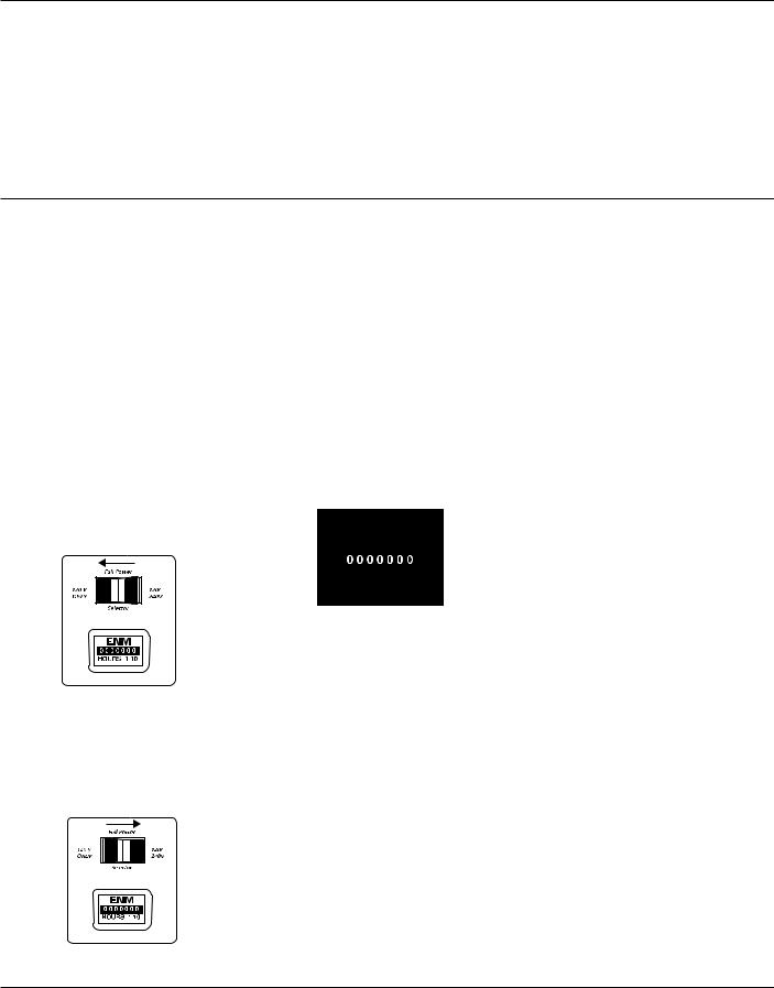
FULL POWER SELECTOR SWITCH
All models except 3W735B, 3WY47, and 3WY45 have a full power selector switch on the control panel. The switch has two positions: 120 VOLT ONLY, and 120/240 VOLT.
120 VOLT ONLY: This position sends full power to the 120V receptacles only. 240V power is not available. Use this position when powering 120V items only.
Figure 5 – Full Power Selector Switch in 120 Volt Only Position
120/240 VOLT: This position sends full power to the 120/240V receptacle. It also powers the 120V receptacles at reduced wattage capacity.
Figure 6 – Full Power Selector Switch in 120/240 Volt Position
IMPORTANT: Do not move the full power selector switch while powering electrical items. Unplug all items before moving switch. Failure to do so can damage switch.
Models 3W735B, 3WY45, and 3WY47 do not have this switch. These models provide full power to all receptacles.
HOUR METER
All models except 3W735B have an hour meter. The hour meter is on the control panel. The hour meter shows the total generator run time, including all idle time (See Figure 7). Hour meter is accurate up to 1/10 of an hour.
Figure 7 – Hour Meter
AUTO-IDLE SYSTEM
The auto-idle system allows the engine to idle down or run at a slower speed when the generator is not being used to supply power. The auto-idle system can be turned ON or OFF by a rocker switch on the control panel. When the switch is in the OFF position, the engine runs at full speed all of the time. When the switch is in the ON position, the engine slows down to idle speed until an electrical load is applied. When a load is applied to the generator (an electrical item is plugged in and turned on) the engine speeds up to the preset speed required to produce the correct voltage.
IMPORTANT: A minimum current load of 1 Amp is required to disengage the auto idle solenoid and cause the engine to come up to speed for correct voltage.
Powering items at reduced engine speed will damage generator and powered items.
ELECTRIC START (MODELS 3WY46, 3WY45, AND 3WY47 ONLY)
Models 3WY46, 3WY45, and 3WY47 have an electric starter. A battery is not supplied with generator. You must provide a 12volt, 32-amp-hour battery. For more battery information, see “Battery,” page 8.
GROUND FAULT CIRCUIT INTERRUPTER RECEPTACLE
All models have a 120-volt ground fault circuit interrupter (GFCI) receptacle. The GFCI receptacle is on the control panel or top cover of alternator (Model 3W735B only). The GFCI protects you against hazardous electrical shock caused when your body becomes a path through which electricity travels to reach ground. This could happen when you touch an appliance or cord that is ‘live’ through faulty mechanism, damp or worn insulation, etc.
When protected by the GFCI, you may still feel a shock, but the GFCI should cut it off quickly. A person in normal health should not receive serious injury.
NOTE: Infants and very small children may still be affected.
TEST PROCEDURE
Check the GFCI receptacle every month. This insures it is working right.
1.Push black TEST button. Red RESET button should pop out. This should trip GFCI, resulting in no electrical power at receptacle. Verify this by plugging test lamp with good bulb into receptacle. If lamp does not work, GFCI receptacle is good.
6
Dayton Operating Instructions and Parts Manual
Models 3WY47, 3W735B, 3W736C, 3WY44, 3TE27A, 3WY45, and 3WY46
Generator Features (Continued)
If RESET button does not pop out,
do not use the GFCI receptacle. Contact a qualified electrician for repairs.
2.If the GFCI receptacle tests okay, restore power by pushing the RESET button back in. The test lamp should work at this time.
IMPORTANT: You must press the RESET button firmly and fully. It should lock into place. If the GFCI does not lock into place, do not use receptacle. Contact a qualified electrician for repairs.
RESET
TEST
Figure 8 - GFCI Receptacle
ENGINE CIRCUIT BREAKER (MODELS 3WY46 AND 3WY45 ONLY)
This circuit breaker protects the battery charging circuit. A short circuit will trip the circuit breaker. The circuit breaker will also trip if you install battery wrong. Push circuit breaker button to reset. Model 3WY47: Fuse located inside keyswitch box.
ON
OFF 
 START
START
ENGINE SW
CIRCUIT
BREAKER
Engine Circuit ON/push OFF
Breaker Button
RECEPTACLE CIRCUIT BREAKER
Model 3W735B has only one receptacle circuit breaker. All other models have four, except Model 3WY47 which has six. The circuit breakers protect the receptacles and alternator. Overloading generator will trip circuit breaker. A short circuit in item being powered will also trip breaker. If this occurs, unplug electrical load from receptacle. Let circuit breaker cool down. Push circuit breaker button to reset.
20 20
20
Normal Tripped
Figure 10 – Receptacle Circuit Breaker Button
Electric motors need higher starting current. They require up to 3 to 6-times their rated full-load wattage to start. The starting current needed may be too high. This can cause nuisance circuit breaker tripping. To help prevent this, start electric motors first. Connect additional items to generator after starting motors. If this continues to happen, reduce the total generator load.
NOTE: High ambient temperatures will cause nuisance tripping.
Assembly
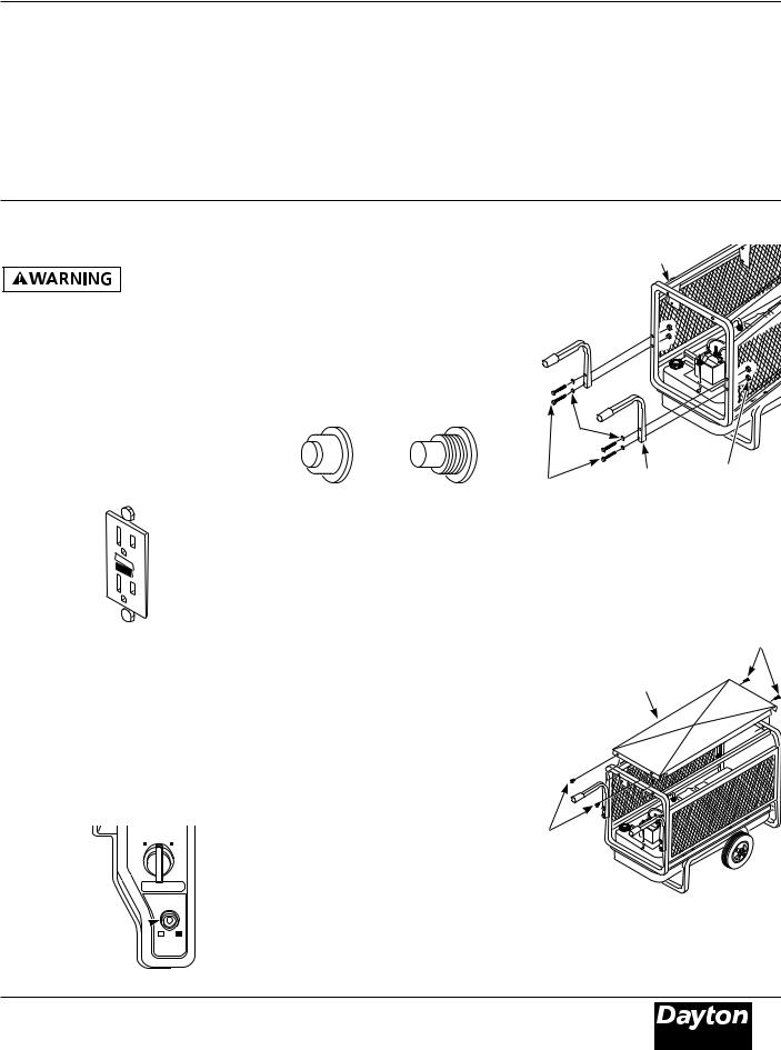
HANDLE AND TOP COVER ASSEMBLY (MODEL 3WY47 ONLY)
1.Remove the two bolts, lock nuts, and washers holding side panels to control panel end of roll cage. Insert bolts with washers through two holes in the handle and then back through roll cage and side screen panels (See Figure 11 ). Tighten the lock nuts against the side screen panels.
Roll Cage
Washers |
Handle Lock Nuts
Bolts
Figure 11 – Attaching Handles to Roll Cage
2.Place top cover on top of generator roll cage with notch on control panel side. Use four #8 sems screws provided to attach cover to roll cage (See Figure 12).
SEMS Screws
Top Cover
SEMS
Screws
Figure 12 – Attaching Top Cover to Roll Cage
Figure 9 – Engine Circuit Breaker
®
7
Version B - For Reduction |
G016.J |
Dayton Operating Instructions and Parts Manual |
3WY47, 3W735B, 3W736C, 3WY44, 3TE27A, 3WY45, and 3WY46 |
Dayton® Professional-Duty
Electric Generators
Assembly (Continued)
BATTERY (MODELS 3WY46, 3WY45, AND 3WY47 ONLY)
Battery gives off explosive gases.
Keep sparks, flames, and cigarettes away. Do not remove or install battery cables when engine is cranking or running. Only service or use battery in a well-vented area.
Battery contains sulfuric acid.
Contact with skin or eyes may cause severe burns. Do not tilt generator with battery installed. Tilting could cause battery acid to spill. Wear protective clothing and face shield when servicing. Keep out of children’s reach.
•If battery acid gets on your skin, wash with water.
•If battery acid gets in your eyes, flush with water at least 15 minutes. Call a doctor at once.
Battery acid is poisonous.
•If swallowed, drink large amounts of water or milk. Follow with milk
of magnesia or vegetable oil. Call a doctor at once.
If you remove battery, insulate
the red, positive (+) battery cable terminal. Insulate with electrical tape. Exposed terminal may spark when generator runs.
IMPORTANT: Make sure battery connections are the correct polarity. Electric start generators use negative ground, 12-volt DC starting system.
Models 3WY46, 3WY45, and 3WY47 have an electric starter. A battery is not supplied with generator. You must provide a 12volt, 32-amp-hour battery. The positive and negative battery cables are supplied with generator. You must install these cables before mounting battery.
Always wear safety glasses when working with battery. Make sure battery terminals are clean. Make sure cable connections are tight.
Always shut down engine before removing or attaching battery cables. Always remove the negative (–) cable first. Always attach negative (–) cable last.
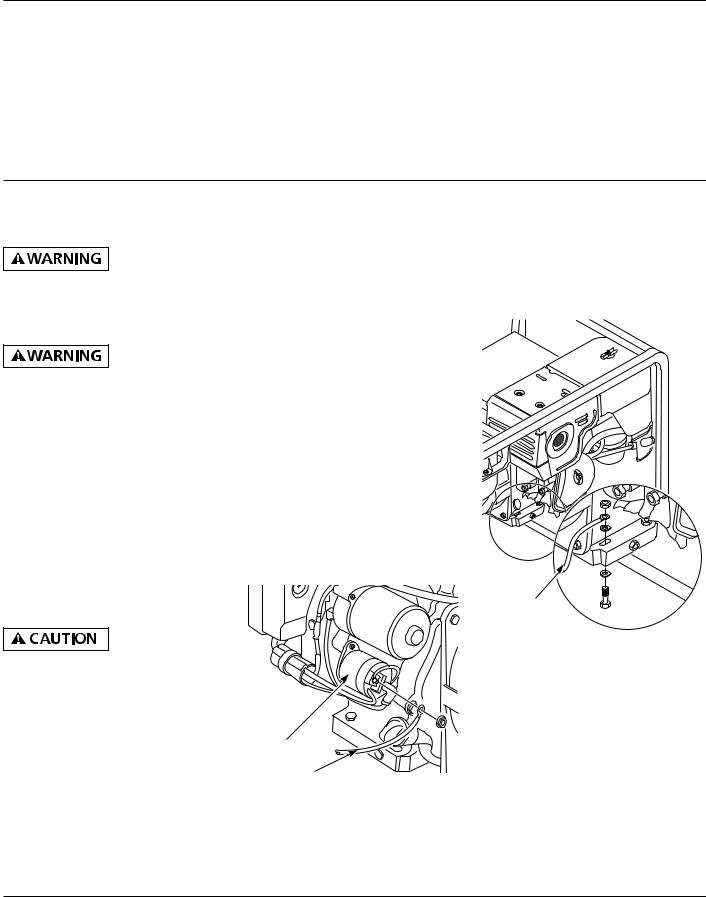
INSTALLING BATTERY CABLES TO ENGINE
1.Attach the red, positive (+) battery cable to the starter solenoid on engine (See Figure 13). The starter solenoid is located directly above the starter on Model 3WY47. This cable is factory installed.
Starter
Solenoid
Red, Positive (+) Battery Cable
Figure 13 – Connecting Red, Positive (+) Battery Cable to Starter Solenoid on Engine (Model 3WY45 Shown)
2.Attach the black, negative (–) battery cable to the engine block. Use the bolt, nut, and two washers provided with the battery cables. Use long mounting hole on opposite side of engine from starter solenoid. Attach cable as shown in Figure 14.
Black, Negative
(–) Battery
Cable
Figure 14 – Connecting Black, Negative (–) Battery Cable to Engine Block
8
Dayton Operating Instructions and Parts Manual
Models 3WY47, 3W735B, 3W736C, 3WY44, 3TE27A, 3WY45, and 3WY46
Assembly (Continued)
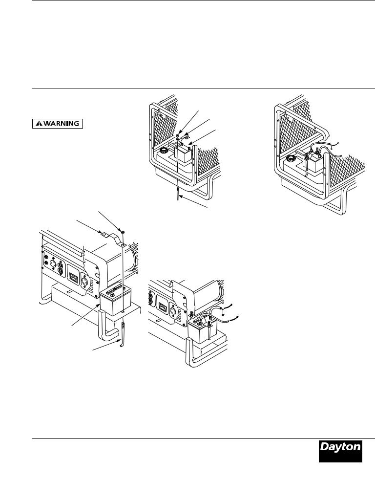
MOUNTING BATTERY TO GENERATOR
Do not over tighten positive terminal on
starter solenoid. Positive terminal could rotate and cut into negative terminal, causing a short.
NOTE: Model 3WY47 battery is located on opposite side as shown (See Figure 16).
1.Secure battery to generator by battery hold-down system. This system consists of the battery mounting bracket, hook bolt, and nut (See Figures 15 and 16).
Nut
Battery Mounting
Bracket
Nut
Battery Mounting
Bracket
Battery
Hook Bolt
Figure 16 – Battery Hold-Down System
(Model 3WY47 Shown)
|
|
2. Locate the red, positive (+) battery cable |
|
|
|
from starter solenoid. Connect it to the |
|
|
|
positive (+) battery terminal (See Figures |
|
|
|
17 and 18). |
|
0 |
100 |
200 |
|
|
|
|
|
|
|
30 |
|
|
|
|
To |
|
|
|
Engine |
|
|
0 |
Block |
|
|
100 |
|
|
|
|
200 |
|
|
|
30 |
Battery |
|
|
To Starter |
|
|
|
Solenoid |
Hook Bolt |
|
||
Figure 15 – Battery Hold-Down System |
|
||
(Model 3WY45 Shown) |
|
||
To Engine
Block
To Starter
 Solenoid
Figure 18 – Connecting Positive and Negative Cables to Battery (Model 3WY47 Shown)
3.Locate the black, negative (–) battery cable attached to engine block. Connect it to the negative (–) battery terminal (See Figure 16).
4.Check battery before starting engine. Make sure fluid levels are full. Make sure battery is charged.
See engine owner’s manual for more information.
Figure 17 – Connecting Positive and
Negative Cables to Battery (Model 3WY45
Shown)
®
9
Version B - For Reduction |
G016.J |
Dayton Operating Instructions and Parts Manual |
3WY47, 3W735B, 3W736C, 3WY44, 3TE27A, 3WY45, and 3WY46 |
Dayton® Professional-Duty
Electric Generators
Installation
FUEL
Gasoline presents a hazard of fire or explosion. Gasoline
is flammable. Its vapor is explosive.
•Keep fuel out of children’s reach.
•Refuel generator in a well-vented area. Do not fill fuel tank in the dark. Do not refuel while engine is running. Unhook all electrical loads and shut off engine before refueling.
•Do not overfill fuel tank. Always allow room for fuel to expand. If you overfill tank, fuel can overflow onto hot engine. This can cause fire or explosion. After refueling, tightly close fuel tank cap.
•Do not spill fuel. Fuel or fuel vapor may ignite. If fuel spills, make sure area is dry before starting engine.
•Never smoke in refueling area. Never allow open flames or sparks in area.
•Store fuel in approved container. Store fuel in a well-vented area free of open flames or sparks.
Use clean, fresh, unleaded gasoline. Use gasoline with octane rating of 86 or higher. Service station gasoline pumps should display the octane rating. Using gasoline with lower octane level could damage engine. Avoid getting dirt, dust, or water in fuel tank. Do not mix oil with gasoline. See engine owner’s manual for more information.
ENGINE OIL
We ship the generator without oil in the engine crankcase. You must add oil before starting engine. See engine owner’s manual for specific oil type.
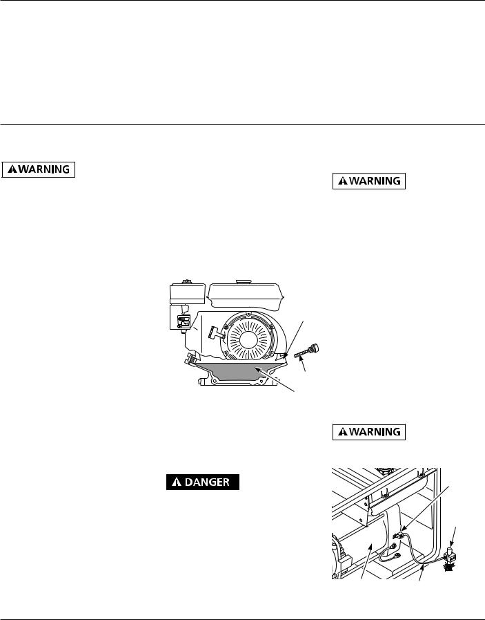
CHECKING OIL LEVEL AND ADDING OIL
Follow steps below to check oil level. Make sure engine is level and stopped.
1.Remove dipstick (See Figure 19). Wipe dipstick clean.
2.Insert dipstick into oil filler neck. Do not screw it in. Oil level should be at top of filler neck. Oil should cover most of dipstick. For Model 3WY47 only, oil level should be between two dots on dipstick.
3.If level is low, fill to top of oil filler neck (See Figure 19). Only use oil recommended in engine owner’s manual. For Model 3WY47 only, fill to top dot on dipstick.
 Oil Level
At Top
Of Filler
Neck
Dipstick
Oil
Figure 19 – Checking Oil Level (Model
3W735B Shown)
NOTE: If oil level is too low, oil alert system will shutdown engine and prevent engine from restarting.
VENTILATION
Use only in wellvented areas. Make
sure area has plenty of free-moving, fresh, outside air. Never run generator in an enclosed or confined area. Never run generator inside occupied building. Engine exhaust contains poisonous carbon monoxide gas. Overexposure will cause loss of consciousness and will lead to death.
This generator needs cooling air to run properly. Never block free-flowing, cooling air to generator. Overheating will occur without cooling air. This will damage the
generator. Keep generator at least three feet away from any object.
GENERATOR GROUNDING
You must properly earth-ground
generator before starting. This will help guard against deadly electric shock. Only use grounded plugs with generator. Only use grounded extension cords. Only use three-wire or double-insulated power tools.
Grounding generator helps prevent electric shock from a ground fault condition.
Locate ground lug on end of generator housing (See Figure 20). Attach a #10 stranded-copper ground wire to ground lug. Drive grounding point into ground. Grounding point can be a stake, grounding rod, or pipe. Grounding point should be copper or brass. Attach ground wire to grounding point. You must supply the ground wire and grounding point. These do not come with generator. Follow the National Electrical Code and all state and local codes. Consult your power company or a licensed electrician.
For a grounding point, do not use
metal pipe being used to carry combustible materials or gases.
Ground
Lug
Copper or
Brass
Grounding
Point
Alternator |
Ground Wire |
Figure 20 – Grounding Generator
(Model 3WY45 Shown)
10
Dayton Operating Instructions and Parts Manual
Models 3WY47, 3W735B, 3W736C, 3WY44, 3TE27A, 3WY45, and 3WY46
Installation (Continued)
DUST, DIRT, RAIN, AND SNOW
Do not use generator out-
doors in rain or snow. Do not use generator near standing water or snow. Do not use if generator is wet or damp. Operating generator in these conditions increases the risk of electrocution. Severe injury or death can occur.
Do not use generator in extremely dusty or dirty conditions. This will severely affect its life. Keep generator clean. Do not allow dust, dirt, rain, or snow to collect on it. Protect generator from outdoor elements.
EXTENSION CORDS
Only use grounded extension cords. Be sure to use extension cord with proper wire gauge size. See chart below.
RECOMMENDED MINIMUM WIRE GAUGES (AWG) FOR EXTENSION CORDS
Ampere |
AWG for |
AWG for |
AWG for |
Load |
50' Cord |
100' Cord |
150' Cord |
2 |
18 |
18 |
18 |
3 |
18 |
18 |
18 |
4 |
16 |
16 |
16 |
5 |
16 |
16 |
16 |
6 |
16 |
16 |
14 |
8 |
16 |
14 |
12 |
10 |
16 |
14 |
12 |
12 |
14 |
14 |
12 |
|
|
|
|
14 |
14 |
12 |
10 |
16 |
12 |
12 |
10 |
20 |
10 |
10 |
8 |
GROUND FAULT PROTECTION
Ground Fault Circuit Interrupter (GFCI) helps guard against electric shock. On
construction sites, you must use a GFCI. United States OSHA and the National Electric Code requires this.
You may need to provide the GFCI device. Purchase GFCI at any electrical supply house. Check the Yellow Pages for the nearest supply house.
STANDBY INSTALLATION TO HOME OR BUILDING
Have standby installation
performed by a skilled, licensed electrician. Do not let anyone else wire into a utility circuit. Personal injury, equipment damage, or damage to home could occur.
IMPORTANT: This generator will not power your entire home. Most home utility electric service is more than 60 amps. This will exceed generator output. Only power needed items during a power outage. Make sure total wattage of electrical load does not exceed rated wattage of generator.
You can use this generator as a standby power source. During a power outage, the generator will power selected items in a building. Have generator and additional wiring installed by a skilled, licensed electrician. This is not a do-it-yourself job. Follow all local codes.
The electrician must install a double-
throw transfer switch. This isolates existing electrical circuits from the utility power line. If not isolated, generator output will back-feed into utility power line. This may electrocute a power company line repair person.
DETERMINING ELECTRICAL LOAD FOR GENERATOR
You must decide what electrical load your generator can power. Do this before using
generator. Use the following four-step method. It will help you select a load that is not too large. Make sure total wattage of all electrical loads does not exceed rated wattage of generator. For rated wattage of your generator, see “Electrical Specifications,” page 2. Electric motors present a special problem when figuring load. Read Step 3 carefully.
1.Make two lists of items you want powered by generator. List all motors and motor powered appliances in one. List all lights, small appliances, etc. in the other. For standby service to home or building, only include items you must power.
2.Enter running watts of each item except motors. The light bulb or appliance nameplate lists its wattage. Remember, 1KW = 1000 watts.
NOTE: The nameplate may not list wattage. It may only list volts and amps. The formula for finding wattage is: Volts x Amps = Watts. For example: An appliance nameplate states 3 amps at 120 volts. 3 amps x 120 volts = 360 watts.
3.Electric motors present a special problem. They require 3 to 6 times their rated full load wattage to start. Chart 1, on page 12, shows starting watts (maximum volt-amperes [VA]) for different size motors. For example: an electric motor nameplate states 5 amps at 120 volts. 5 amps x 120 volts = 600 watts running. Multiply this figure by 3. This will show the starting watts (maximum VA) needed. 600 watts x 3 = 1800 watts (VA) to start. When figuring the generator load for motors, you must use the starting watts (maximum VA) figure. Do not use the running watts figure.
®
11
Version B - For Reduction |
G016.J |

Dayton Operating Instructions and Parts Manual |
3WY47, 3W735B, 3W736C, 3WY44, 3TE27A, 3WY45, and 3WY46 |
Dayton® Professional-Duty
Electric Generators
Installation (Continued)
NOTE: Some motors require nearly the same wattage to run as to start. These items include saws, drills, hair dryers, and food mixers. See Chart 2 for typical appliance wattage examples.
4.Add watts and starting watts (maximum VA) of all items. This total must not be larger than the rated wattage of your generator. It is a good idea to have up to 25% extra capacity for future needs or extra equipment.
CHART 1
TYPICAL ELECTRIC APPLIANCE WATTAGES
Chart to be used as reference. Data may vary with size, make, and/or model.
CHART 2
|
|
Starting |
|
Running |
Watts |
Equipment |
Watts |
(Max.VA) |
Light bulb (100W) |
100 |
100 |
Radio |
150 |
150 |
Fan |
200 |
600 |
Television |
400 |
400 |
Furnace fan—1/3 HP with blower |
600 |
1800-2400 |
Vacuum cleaner |
600 |
750 |
|
|
|
Sump pump—1/3 HP |
700 |
2100-2800 |
Refrigerator/freezer |
800 |
5000 |
6" Circular saw |
800 |
1000 |
Floodlight |
1000 |
1000 |
1/2" Drill |
1000 |
1250 |
|
|
|
Toaster/coffeemaker |
1200 |
1200 |
Skillet |
1200 |
1200 |
14" Chain saw |
1200 |
1500 |
Water well pump—1/2 HP |
1000 |
3000-6000 |
Hot plate/range (per burner) |
1500 |
1500 |
|
|
|
10" Table saw |
2000 |
6000 |
Water heater (storage-type) |
5000 |
5000 |
|
|
Approximate |
Approximate |
Approximate |
Approximate |
|
|
Starting Watts* |
Starting Watts* |
Starting Watts* |
Starting Watts* |
Motor |
Approximate |
(Max. VA) |
(Max. VA) |
(Max. VA) |
(Max. VA) |
HP |
Running |
Universal Motors |
Repulsion |
Capacitor |
Split Phase |
Rating |
Watts |
(small appliance) |
Induction Motors |
Motors |
Motors |
1/8 |
275 |
400 |
600 |
850 |
1200 |
1/4 |
400 |
500 |
850 |
1050 |
1700 |
1/3 |
450 |
600 |
975 |
1350 |
1950 |
1/2 |
600 |
750 |
1300 |
1800 |
2600 |
3/4 |
850 |
1000 |
1900 |
2600 |
† |
|
|
|
|
|
|
1 |
1000 |
1250 |
2300 |
3000 |
† |
11/2 |
1600 |
1750 |
3200 |
4200 |
† |
2 |
2000 |
2350 |
3900 |
5100 |
† |
3 |
3000 |
† |
5200 |
6800 |
† |
(*) Always use starting watts (maximum VA), not running watts, when figuring correct electrical load.
(†) Motors of higher horsepower are not generally used.
Please check with appliance manufacturer for maximum wattage required.
12
 Loading...